JP4093936B2 - Armrest device - Google Patents
Armrest deviceDownload PDFInfo
- Publication number
- JP4093936B2 JP4093936B2JP2003297176AJP2003297176AJP4093936B2JP 4093936 B2JP4093936 B2JP 4093936B2JP 2003297176 AJP2003297176 AJP 2003297176AJP 2003297176 AJP2003297176 AJP 2003297176AJP 4093936 B2JP4093936 B2JP 4093936B2
- Authority
- JP
- Japan
- Prior art keywords
- armrest
- slide
- plate
- adjustment mechanism
- strut
- Prior art date
- Legal status (The legal status is an assumption and is not a legal conclusion. Google has not performed a legal analysis and makes no representation as to the accuracy of the status listed.)
- Expired - Fee Related
Links
- 230000007246mechanismEffects0.000claimsdescription53
- 230000005540biological transmissionEffects0.000claimsdescription6
- 230000003028elevating effectEffects0.000claimsdescription4
- 238000005452bendingMethods0.000description1
- 230000037237body shapeEffects0.000description1
- 230000008878couplingEffects0.000description1
- 238000010168coupling processMethods0.000description1
- 238000005859coupling reactionMethods0.000description1
- 239000000463materialSubstances0.000description1
- 239000011347resinSubstances0.000description1
- 229920005989resinPolymers0.000description1
Images


Classifications
- A—HUMAN NECESSITIES
- A47—FURNITURE; DOMESTIC ARTICLES OR APPLIANCES; COFFEE MILLS; SPICE MILLS; SUCTION CLEANERS IN GENERAL
- A47C—CHAIRS; SOFAS; BEDS
- A47C1/00—Chairs adapted for special purposes
- A47C1/02—Reclining or easy chairs
- A47C1/022—Reclining or easy chairs having independently-adjustable supporting parts
- A47C1/03—Reclining or easy chairs having independently-adjustable supporting parts the parts being arm-rests
Landscapes
- Health & Medical Sciences (AREA)
- Dentistry (AREA)
- General Health & Medical Sciences (AREA)
- Seats For Vehicles (AREA)
Description
Translated fromJapanese本発明は、椅子などに装着する肘掛け装置であって、特に、肘掛けの高さや水平面上における角度及び前後位置などを可変できるようにした肘掛け装置に関する。 The present invention relates to an armrest device mounted on a chair or the like, and more particularly to an armrest device that can change the height of the armrest, the angle on the horizontal plane, the front-rear position, and the like.
この種の肘掛け装置は、例えば、OA機器を載置した事務用机などと一対で使用される事務用椅子などに装着され、マウスやキーボードなどの入力手段を操作する際に、使用者の体型や姿勢などに適合するように肘掛けを調整し、身体に無理な負担が掛からないようにしている。 This type of armrest device is mounted on, for example, an office chair or the like used as a pair with an office desk on which OA equipment is placed, and the user's body shape when operating input means such as a mouse or a keyboard. The armrests are adjusted to fit the body and posture so that the body is not overloaded.
このような肘掛け装置については、例えば、特許文献1〜3を含む各種の提案がなされている。特許文献1の場合には、上下の高さ位置調整と前後及び左右の水平スライド調整が可能であり、特許文献2の場合には、垂直角度調整と左右の水平スライド及び水平角度調整が可能であり、特許文献3の場合には、上下の高さ位置調整と左右の水平スライド調整及び水平角度調整が可能である。 For such an armrest device, for example, various proposals including Patent Documents 1 to 3 have been made. In the case of Patent Document 1, vertical height adjustment and front / rear and left / right horizontal slide adjustment are possible, and in Patent Document 2, vertical angle adjustment, left / right horizontal slide and horizontal angle adjustment are possible. In the case of Patent Document 3, vertical height adjustment, horizontal slide adjustment and horizontal angle adjustment are possible.
これら従来技術の調整機構による肘掛け装置の場合には、特に、水平面上での肘掛けの移動を、直線上に沿った前後スライド又は及び左右スライドによって行っているので、水平移動範囲が限定され且つ移動操作を円滑に行うことが困難であると共に、前後スライドさせた際に通常時における肘掛け位置から大幅に移動させることができなかった。
そこで、本発明では、これら従来技術の課題を解決し得る肘掛け装置を提供するものであって、特に水平回転調整機構を設けて肘掛け部を水平面上の広い領域内で所望の位置に容易且つ円滑に設定する位置調整を可能にすると共に、この水平回転調整機構を前後スライド調整機構と併用することによって、一段と広範囲な水平移動が可能にすることを主たる目的とし、さらには簡単な構成で操作が容易な水平角度調整機構と高さ調整機構及び前後スライド調整機構を提供するものである。 Therefore, the present invention provides an armrest device that can solve these problems of the prior art, and in particular, a horizontal rotation adjustment mechanism is provided so that the armrest portion can be easily and smoothly placed at a desired position within a wide area on a horizontal plane. The main purpose is to enable horizontal adjustment over a wide range by using this horizontal rotation adjustment mechanism in combination with the forward / backward slide adjustment mechanism, and operation with a simple configuration. An easy horizontal angle adjustment mechanism, height adjustment mechanism, and front / rear slide adjustment mechanism are provided.
本発明による肘掛け装置は、肘掛けの高さ調整機構を備えた支柱部と、肘掛けの前後スライド調整機構を備えた肘掛け部と、前記支柱部と前記肘掛け部とを連結する回転操作部とを有し、回転操作部は、前後に配置した2体の旋回アームを有し、当該旋回アームの180度の旋回角をもって前記肘掛け部を円周上軌跡に沿って前後及び左右に水平移動させる水平回転調整機構を備えている。(請求項1)An armrest device according to the present invention includes a support column having an armrest height adjustment mechanism, an armrest unit having an armrest back-and-forth slide adjustment mechanism, and a rotation operation unit that connects the support column and the armrest unit. The rotation operation unit hastwo swivel arms arranged at the front and rear, and horizontally rotates the armrest unit back and forth and right and left along a circumferential trajectory witha swivel angle of 180 degrees of the swivel arm. An adjustment mechanism is provided. (Claim 1)
請求項1における回転操作部には、前記支柱部の上端に取り付けた角度制御板と、角度制御板上で回転する回転体を設けた肘掛けの水平角度調整機構を備え、回転体に対して前記旋回アームを回動可能に連結させる形態を採ることができる。(請求項2)The rotary operation unit in the claim 1, comprising an angle control plate attached to the upper end of the strut, the armrest horizontal angle adjusting mechanism having a rotating body which rotates at an angle control plate,the relative rotational body It is possible to adopt a form in which the swivel arm is rotatably connected. (Claim 2)
請求項1、2における水平角度調整機構は、前後に配置した前記2体の旋回アームをそれぞれプーリを介して前記揺動回転体に取り付けると共に、各プーリの間に伝動ベルトを架設して各旋回アームを連動可能に連結させる形態を採ることができる。(請求項3) The horizontal angle adjusting mechanism according to claim 1 or 2 is configured such that the two swivel arms arranged at the front and rear are attached to the swinging rotating body via pulleys, and a transmission belt is installed between the pulleys to rotate each swivel arm. The form which connects an arm so that interlocking is possible can be taken. (Claim 3)
請求項1〜3における支柱部には、前記支柱部には、下端側を固定した内筒部材に対して摺動可能に外筒部材が被着され、上部側に操作レバーを下部側に係止片を設けた昇降操作部材の中間部を、上端が前記回転操作部側と連結される支柱本体に枢着させ、昇降操作部材と支柱本体の両側に側板部材を設けて前記内筒部材内に収容させ、支柱本体には昇降操作部材の下部側を支柱本体側へ付勢するばね部材を設けると共に、側板部材には係止片が係止するラックを設けた高さ調整機構を備えている形態を採ることができる。(請求項4)The column portion according to claims 1 to 3, wherein an outer cylinder member is slidably attached to the column portion with respect to the inner cylinder member having a lower end fixed thereto, and an operation lever is engaged on the lower side. The middle part of the lifting / lowering operation member provided with the stop piece is pivotally attached to the column main body whose upper end is connected to the rotation operation unit side, and side plate members are provided on both sides of the lifting / lowering operation member and the column main body to Thecolumn main body is provided with a spring member for urging the lower side of the elevating operation member toward the column main body side,and the side plate member is provided with a height adjusting mechanism provided with a rack for locking the locking piece. Can take the form. (Claim 4)
請求項1〜4における肘掛け部には、前後方向へスライド可能に嵌合させたスライド案内板とスライド板とを肘掛けパッドと肘掛けカバーの間に設け、スライド板は肘掛けパッド及び肘掛けカバーに対して連動可能に係止されると共に、スライド案内板には肘掛けカバーに設けた遊動案内溝孔を挿通した前記旋回アームの旋回アームが枢着された前後スライド調整機構を備えている形態を採ることができる。(請求項5)The armrest portion according to any one of claims 1 to4 is provided with a slide guide plate and a slide plate, which are slidably fitted in the front-rear direction, between the armrest pad and the armrest cover, and the slide plate is attached to the armrest pad and the armrest cover. The slide guide plate may have a front and rear slide adjustment mechanism in which the swing arm of the swing arm that is inserted through the floating guide groove hole provided in the armrest cover is pivotally attached. it can. (Claim 5)
請求項1の肘掛け装置では、従来技術でも行われているように、肘掛けの高さ調整や水平面上での角度及び前後スライド調整に加えて、旋回アームによって肘掛け部を前後の向きが変わらない姿勢で水平面上を回転させる水平回転調整機構を設け、肘掛け部を円周上軌跡に沿って前後及び左右に水平移動させることができる。 In the armrest device according to claim 1, as in the prior art, in addition to the height adjustment of the armrest, the angle on the horizontal plane and the front-rear slide adjustment, the posture in which the front and rear orientation of the armrest portion is not changed by the swing arm. Thus, a horizontal rotation adjusting mechanism for rotating on the horizontal plane can be provided, and the armrest portion can be moved horizontally back and forth and right and left along a circumferential locus.
従って、この水平回転調整機構の場合には従来技術のように水平面上で前後スライド調整又は左右スライド調整を単独で行う場合に比べて、肘掛け部を水平面上の広い領域内で所望の位置に容易且つ円滑に設定する水平位置調整が可能であると共に、前後スライド調整機構と併用することによって一段と広範囲な水平移動が可能であり、特に、旋回アームを180度旋回させた状態でスライド調整を行うと、通常位置から大幅に前後移動させることができる。Therefore, in the case of this horizontal rotation adjustment mechanism, the armrest portion can be easily moved to a desired position in a wide area on the horizontal plane, compared to the case where the front / rear slide adjustment or the left / right slide adjustment is performed independently on the horizontal plane as in the prior art. The horizontal position can be adjusted smoothly, and the horizontal movement can be performed in a wider range by using it together with the front / rear slide adjustment mechanism. Especiallywhen the slide adjustment is performed with theswivel arm turned 180 degrees. It can be movedback andforth significantly from the normal position.
請求項2の肘掛け装置では、水平回転調整機構と支柱部の間に水平角度調整機構を設けたことによって、肘掛け部は水平角度調整を行った姿勢で水平回転調整機構による前後及び左右への水平移動操作させることができる。 In the armrest device according to claim 2, by providing a horizontal angle adjustment mechanism between the horizontal rotation adjustment mechanism and the support column, the armrest portion is horizontally adjusted in the horizontal and forward and left and right directions by the horizontal rotation adjustment mechanism in a posture in which the horizontal angle adjustment is performed. Can be moved.
請求項3の肘掛け装置では、2体の旋回アームを各プーリと伝動ベルトによって連動回転させることによって、旋回アームによる肘掛け部の水平回転操作を円滑に行うことができると共に、支柱部上に肘掛け部を安定状態で支持させることができる。 In the armrest device according to claim 3, by horizontally rotating the two swivel arms by the pulleys and the transmission belt, the swivel arm can smoothly perform the horizontal rotation operation of the armrest portion, and the armrest portion on the column portion. Can be supported in a stable state.
請求項4の肘掛け装置では、操作レバーを押圧してラックに対する係止片を開放した状態で、肘掛け部を支柱部に対して押し上げ又は押し下げることによって高さ調整を行い、簡単な構造と簡単な操作によって高さ調整を行うことができる。 In the armrest device according to claim 4, the height is adjusted by pushing up or pushing down the armrest portion with respect to the column portion in a state where the operation lever is pressed to release the locking piece to the rack, and the simple structure and the simple structure are achieved. The height can be adjusted by operation.
請求項5の肘掛け装置では、肘掛け部を前後にスライドさせることによって、水平回転調整機構の旋回アームに連結されたスライド案内板に嵌合したスライド板が、肘掛けパッド及び肘掛けカバーに連動して前後スライド調整を行い、簡単な構造と簡単な操作によって前後スライド調整を行うことができる。 In the armrest device according to
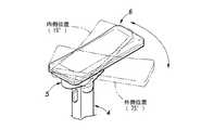
本発明による肘掛け装置について、本発明を適用した好適な実施例を示す添付図面に基づいて詳細に説明する。肘掛け装置1は、図1で示すように、座席2を備えた椅子本体側の側面に連結具3を介して取り付けられており、図2で示すように、鉛直な支柱部4と、支柱部4の上端に回転操作部5を介して取り付けられた肘掛け部6とを有する。An armrest device according to the present invention will be described in detail with reference to the accompanying drawings showing a preferred embodiment to which the present invention is applied. As shown in FIG. 1, the armrest device 1 is attached to a side surface on the chair body side provided with a seat 2 via a connector 3, and as shown in FIG. 2, avertical column part 4 and a column part 4has an
肘掛け装置1は、図3〜図6の分解斜視図のように、高さ調整機構を備えた支柱部4を構成する図3に示す下部側部分と、回転操作部5を構成する図4及び図5に示す中間部分と、前後スライド可能な肘掛け部6を構成する図6に示す上部側部分とを有し、これら各部分が連結されることにより、図7〜図9に示す組立状態になる。As shown in the exploded perspective views of FIGS. 3 to 6, the armrest device 1 includes a lower side portion shown in FIG. 3 that constitutesa column portion 4provided with a height adjustment mechanism, and a
図3に示されている下部側部分は、連結具3として、一端側の連結板8によって椅子本体側に固定される支持アーム7を有する。支持アーム7の他端側には方形筒状の内筒部材9が鉛直に固定装着されている。内筒部材9の下端には蓋部材11が被着固定されている。内筒部材9の外側には外筒部材10が上下方向へ摺動可能に嵌合している。The lower side portionshown in FIG. 3 hasa
支柱部4は、支柱本体12と、支柱本体12の一方側面に配置された昇降操作部材13と、支柱本体12の両側に配置される左右一対の側板部材14,15を備えている。昇降操作部材13は、支柱本体12に対して揺動支点となる中間部を枢着軸16によって連結されている。支柱本体12の下端側に設けられたばね受け部17と支柱本体12のばね受け部18との間にはコイルばねなどによる付勢ばね部材19が装着されている。支柱本体12の下端側には係止片20が設けられており、係止片20は支柱本体12に形成された窓孔21内に進入している。The column part 4 includes a
支柱本体12の上端部には円盤状の連結板22が一体的に設けられている。連結板22は、中央部にボス23を、ボス23の両側に係止ピン24を突出形成されている。
昇降操作部材13は上端側に操作レバー25を有する。側板部材14,15の板面には、ラック26a,27aを形成された切欠溝孔26,27が開口している。側板部材14,15の下端には2つ割した支持筒30(30A,30B)が設けられている。Adisc-shaped connecting
The
支柱部4は、支柱本体12に対して昇降操作部材13を連結すると共に、その両側に側板部材14,15を装着した状態で内筒部材9内に収容される。支柱本体12の連結板22は外筒部材10の上端に形成した環状の受け台28上に載置される。側板部材14,15は内筒部材9に固定される。昇降操作部材13の操作レバー25は外筒部材10の上端側側面に形成した開口部29から外方に突出する。側板部材14,15の支持筒30(30A,30B)は蓋部材11に形成した受け筒31内に嵌合装着される。The column part 4 is accommodatedin the
以上の構成による支柱部4は、支柱本体12と昇降操作部材13及び側板部材14,15を主要部材として、内筒部材9に対して外筒部材10を昇降移動させて肘掛け部6の高さ調整を行う高さ調整機構を含む。高さ調整機構は、常時には、肘掛け部6を任意の高さ位置でロック状態にし、操作レバー25の操作でロック状態を解除して肘掛け部6を所望の高さ位置に変えることができる。The column portion 4 having the above-described configuration has the
すなわち、常時には、付勢ばね部材19の付勢力によって、支柱本体12の窓孔21から突出した係止片20が側板部材15のラック27aに係合してロック状態である。操作レバー25を押圧すると、付勢ばね部材19の付勢力に抗して枢着軸16を支点に昇降操作部材13が揺動し、係止片20が後退してラック27aとの係合が解除される。この状態で、支柱本体12と共に外筒部材10を引き上げ又は引き下げ、肘掛け部6が所望の高さ位置にした後に、操作レバー25の押圧を停止すると、肘掛け部6が調整後の高さ位置にロックされる。That is, normally, the latching
中間部分は、図2、図4、図5に示されているように、支柱部4の上端側に連結される下部連結体5Aと、肘掛け部6の底面側に連結される上部連結体5Bとによって回転操作部5を構成している。下部連結体5Aには、水平面上で内外へ所定角度範囲で回動変位可能で、肘掛け部6の首振り操作を行う水平角度調整機構が組み込まれ、上部連結体5B側には、水平面上で旋回変位可能で、肘掛け部6の横及び前後移動を行う水平回転調整機構が組み込まれている。Asshown in FIGS. 2, 4, and 5, the intermediate portion includes a lower connecting
下部連結体5Aに組み込まれる水平角度調整機構は、角度制御板32、回転体33及び摺動リング34を主要部材とし、これらを支柱部4の上部に取り付けて構成されている。角度制御板32は、揺動範囲の両側に回転角度を規制する係止部35と、係止部35間の座面に所定角度間隔毎にリブを放射状に設けてなるラック36とを有する。角度制御板32は、位置決め孔37をもって支柱本体12の連結板22に形成された係止ピン24に嵌合し、ボス23の外周に軸心孔38を同心円状に配置される。Thehorizontal angle adjusting mechanism incorporated in the lower connecting
回転体33は、上部側の外形が略楕円状をした箱形で軸心に向けて傾斜状の底面を有する連結カバー39を主体とし、軸心の底面側から二重筒に突設した連結筒部40と、底面から上方へ突設したボス41とを備える。支柱本体12のボス23の外周と角度制御板32の軸心孔38の内周の間には、二重筒状の下部側の摺動リング34Aが挿入されており、連結カバー39の連結筒部40の内筒が摺動リング34Aの溝孔に嵌合し、連結筒部40の外筒が角度制御板32の外周に嵌合している。The
フランジ付き筒状の上部側の摺動リング34Bは連結筒部40の内筒に嵌合しており、その上から、ばね座金42と平座金43を挟んでねじ44を連結板22のボス23に設けたねじ穴に螺着する。これにより、回転体33は、支柱本体12に固定の角度制御板32に対して回転可能に連結され、角度制御板32の係止部35によって回転可能角度を規制され、ラック36によって一定角度ずつ段階的に揺動回転する水平角度調整機構をなす。The flanged
上部連結体5Bに組み込まれる水平回転調整機構は、プーリ45(45A,45B)、伝動ベルト46及び旋回アーム47(47A,47B)を主要部材とし、これらを下部連結体5Aの上部に取り付けて構成されている。プーリ45A,45Bは、各々、二重筒状の下部側の摺動リング48Aを介して連結カバー39のボス41の外周に回転可能に嵌合し、当該プーリに掛け渡された伝動ベルト46によって連動回転する。プーリ45A,45B間には保持板49が配置されている。Horizontal rotation adjustment mechanism incorporated in the upper connecting
旋回アーム47A,47Bは、各々、ばね座金51、平座金52、取付孔50に嵌められた上下の摺動リング48A、48Bを挟んでボス41に設けたねじ穴に螺着したねじ53によってボス41に対して回転可能に抜け止め装着されている。The
旋回アーム47の旋回端側にはボス54が突設され、ボス54の外周は環状溝穴55が形成されている。旋回アーム47は、ボス54及び環状溝穴55を介して詳細を後述するように、肘掛け部6側に連結されている。
この水平回転調整機構では、旋回アーム47A,47Bの一方を回転させると他方が連動回転し、旋回アーム47A,47Bは円周上の軌跡を描いて旋回するので、旋回アーム47A,47Bに連結した肘掛け部6は、支柱部4上で左右及び前後方向へ移動させることができる。A
In this horizontal rotation adjusting mechanism, when one of the
上部側部分には、肘掛けカバー56とスライド案内板57とスライド板58及び肘掛けパッド59を主要部材として肘掛け部6が構成されている。 In the upper side portion, an
肘掛けカバー56と肘掛けパッド59は、いずれも略方形状をした浅い箱形形状であって、肘掛けパッド59の内面側の四隅にボス60を突設され、肘掛けカバー56の内面側の四隅に通孔を備えたボス60の受け座金61を形成され、受け座金61の通孔に挿入した止めねじ62をボス60のねじ穴に螺着して一体の箱形に形成される。肘掛けカバー56には旋回アーム47A,47Bの先端側が回動可能に嵌合する幅広の長円形状をした遊動案内溝63(63A,63B)が開口形成されている。Each of the
スライド案内板57は板面の長手方向に沿った両側に係合用突片64を有し、係合用突片64には樹脂材などで形成した摺動片65が被着されている。スライド板58には板面の長手方向に沿った両側をコ字状に折り曲げた摺動溝67が形成されている。摺動片65を摺動溝67に差し込むことにより、スライド案内板57とスライド板58が長手方向へ摺動可能な状態で連結されている。つまり、スライド板58は、スライド案内板57に対して前後方向へスライド可能に係合した状態で、肘掛けカバー56と肘掛けパッド59の間に収容され、且つ肘掛けカバー56、肘掛けパッド59に対して固定されている。The
スライド案内板57は、遊動案内溝63A,63Bに嵌合している旋回アーム47の先端のボス54周りの環状溝穴55に嵌合した下側の摺動リング69A(69)と、スライド案内板57の下底面側に設けた筒状突起66の中空孔に嵌合した上側の摺動リング69B(69)とを整合させ、これらと、ばね座金70、平座金71を挟んでねじ72をボス54に設けたねじ穴に螺着することにより、旋回アーム47に連結される。The
上部連結体5B側に連結されたスライド板58は、肘掛けパッド59及び肘掛けカバー56に対しては肘掛けパッド59の内面四隅に突設されたボス60によって前後及び左右の動きを規制され、スライド案内板57に対してはスライド溝孔68(68A,68B)内に頭部を突出させたねじ72によって左右の動きを規制された状態で、肘掛けパッド59及び肘掛けカバー56の動きに連動し、スライド案内板57に対してスライド溝孔68に沿った前後方向へねじ72の頭部がスライド溝孔68(68A,68B)を可動できる範囲内でスライドが可能である。The
以上の構成による肘掛け部6では、上部連結体5B側に連結されたスライド案内板57と、スライド案内板57に対して摺動可能なスライド板58によって前後スライド調整機構が構成され、肘掛けパッド59を前後方向にスライドさせると、回転操作部5側に固着されているスライド案内板57との間で、肘掛けカバー56及びスライド板58と一緒に前後方向へ移動させることができる。 In the
次に、各調整機構について図10〜14で説明する。支柱部4に設けた高さ調整機構は、図示の実施例の場合には、図10に示すように、肘掛け部6の高さ位置は下降位置と上昇位置の間を110mmの可動範囲で昇降移動できる。この可動範囲は支柱本体12や昇降操作部材13及び側板部材14,15などの主要部材の長さを変えることによって、任意に設定することができる。Next, each adjustment mechanism will be described with reference to FIGS. In the case of the illustrated embodiment, as shown in FIG. 10, the height adjustment mechanism provided on the support column 4 moves up and down within a movable range of 110 mm between the lowered position and the raised position. I can move. This movable range can be arbitrarily set by changing the lengths of main members such as the column
下部連結体5Aに設けた水平角度調整機構は、図示の実施例の場合には、図11に示すように、内側位置へ15度と外側位置へ75度の位置に各係止片35を設け、90度の移動範囲で揺動回転するように設定されている。係止片35の位置を変えることによって移動範囲を任意に設定することができる。 In the case of the illustrated embodiment, the horizontal angle adjusting mechanism provided on the lower connecting
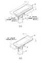
上部連結体5Bに設けた水平回転調整機構は、図14に示すように、通常時は、旋回アーム47(47A,47B)が肘掛け部6の長手方向に沿って直列状態で整列しており、旋回アーム47を90度回転させた場合には、旋回アーム47が肘掛け部6の短手方向に沿って並列状態で整列し、その間に肘掛け部6は向きを一定にした状態で円周上の軌跡を描きながら旋回して横方向及び後方向へ移動する。これにより、図示の実施例の場合には、図12(a)で示すように、肘掛け部6は、左又は右に30mmと後へ30mm移動する。As shown in FIG. 14, the horizontal rotation adjusting mechanism provided in the
また、この状態から更に90度すなわち通常時より180度回転させると、旋回アーム47は通常時とは逆向きの状態で肘掛け部6の長手方向に沿って直列状態で整列する。これによって横方向は通常時の状態に復帰するが、後方向へは更に移動させることができる。図示の実施例の場合には、図12(b)に示すように、図12(a)の状態から更に後へ30mm移動して通常時の状態から60mm移動するように設定されている。この後退位置は支柱部4の直上位置に対する肘掛け部6の前後の長さ寸法を、アンバランスにして寸法差を持たせることによって所望に設定することが可能である。 Further, when the state is further rotated by 90 degrees, that is, 180 degrees from the normal state, the
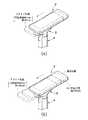
肘掛け部6に設けた前後スライド調整機構は、図示の実施例の場合には、図13(a)に示すように、肘掛け部6は通常時の状態より40mmスライドして後退するように設定されている。特に、図14に示すように、水平回転調整機構と前後スライド調整機構を組み合わせて使用すると、可動範囲を一段と大きく設定することが可能であり、図示の実施例の場合には図13(b)で示すように、180度回転位置で60mm後退して更にスライドによって40mm後退するので、合計では100mm後退させることができる。 In the illustrated embodiment, the forward / backward slide adjustment mechanism provided on the
なお、図示の実施例では支柱部4の直上位置に対して、肘掛け部6は前方側を長く後方側を短く形成し、これによって水平回転調整及び前後スライド調整を行った際に肘掛け部6が通常時より後方側へ移動するようにしているが、肘掛け部6の前方側を短く後方側を長く形成して、水平回転調整及び前後スライド調整を行った際に肘掛け部6が通常時より前方側へ移動する形態を採ることもできる。 In the illustrated embodiment, the
以上のように、肘掛け装置1では従来行われている高さ位置調整や水平角度調整及び前後スライド調整を行うことができると共に、これに加えて支柱部4と肘掛け部6の回転操作部に水平回転調整機構を設け、旋回アーム47を時計方向又は反時計方向へ旋回させることによって、肘掛け部6は向きを一定方向にした状態で左右方向及び前後方向へ水平移動させることが可能である。 As described above, the armrest device 1 can perform conventional height position adjustment, horizontal angle adjustment, and front / rear slide adjustment, and in addition to this, the support unit 4 and the
特に、水平回転調整と前後スライド調整を併用することによって、旋回する旋回アーム47の任意な水平回転位置から前後スライド調整を行うことができると共に、通常状態から180度回転した位置では、前後スライド調整を単独で行った場合に比べて、肘掛け部6の移動範囲を大きくすることができる。 In particular, by using both horizontal rotation adjustment and front / rear slide adjustment, it is possible to perform front / rear slide adjustment from an arbitrary horizontal rotation position of the revolving
図示の実施例では、肘掛け装置を椅子側に取り付けているが、この肘掛け装置を事務用机などの机側に取り付けて使用することも可能である。 In the illustrated embodiment, the armrest device is attached to the chair side, but the armrest device can be attached to a desk side such as an office desk.
1 肘掛け装置
2 (椅子の)座席
3 連結具
4 支柱部
5 回転操作部
5A 下部連結体
5B 上部連結体
6 肘掛け部
7 支持アーム
8 連結板
9 内筒部材
10 外筒部材
11 蓋部材
12 支柱本体
13 昇降操作部材
14,15 側板部材
19 付勢ばね部材(コイルばね)
20 係止片
25 操作レバー
26a,27a ラック
32 角度制御板
33 揺動回転体
45 プーリ
46 伝動ベルト
47 旋回アーム
56 肘掛けカバー
57 スライド案内板
58 スライド板
59 肘掛けパッド
63 遊動案内溝孔
65 摺動片
67 摺動溝
68 スライド溝孔DESCRIPTION OF SYMBOLS 1 Armrest apparatus 2 (Chair) 3 Connection tool 4
DESCRIPTION OF
Claims (5)
Translated fromJapanese回転操作部は、前後に配置した2体の旋回アームを有し、当該旋回アームの180度の旋回角をもって前記肘掛け部を円周上軌跡に沿って前後及び左右に水平移動させる水平回転調整機構を備えていることを特徴とする肘掛け装置。A strut having an armrest height adjusting mechanism, an armrest having an armrest back-and-forth slide adjusting mechanism, and a rotation operation unit connecting the strut and the armrest;
The rotation operation unit hastwo swivel arms arranged at the front and back, and a horizontal rotation adjustment mechanism that horizontally moves the armrest part back and forth and right and left along a circumferential trajectory witha swivel angle of 180 degrees of the swivel arm. An armrest device characterized by comprising:
Priority Applications (1)
| Application Number | Priority Date | Filing Date | Title |
|---|---|---|---|
| JP2003297176AJP4093936B2 (en) | 2003-08-21 | 2003-08-21 | Armrest device |
Applications Claiming Priority (1)
| Application Number | Priority Date | Filing Date | Title |
|---|---|---|---|
| JP2003297176AJP4093936B2 (en) | 2003-08-21 | 2003-08-21 | Armrest device |
Publications (2)
| Publication Number | Publication Date |
|---|---|
| JP2005065815A JP2005065815A (en) | 2005-03-17 |
| JP4093936B2true JP4093936B2 (en) | 2008-06-04 |
Family
ID=34403112
Family Applications (1)
| Application Number | Title | Priority Date | Filing Date |
|---|---|---|---|
| JP2003297176AExpired - Fee RelatedJP4093936B2 (en) | 2003-08-21 | 2003-08-21 | Armrest device |
Country Status (1)
| Country | Link |
|---|---|
| JP (1) | JP4093936B2 (en) |
Cited By (1)
| Publication number | Priority date | Publication date | Assignee | Title |
|---|---|---|---|---|
| CN108784085A (en)* | 2012-09-20 | 2018-11-13 | 斯迪尔科斯公司 | Chair assembly and armrest assembly |
Families Citing this family (10)
| Publication number | Priority date | Publication date | Assignee | Title |
|---|---|---|---|---|
| JP4624208B2 (en)* | 2005-08-08 | 2011-02-02 | タカノ株式会社 | Slide guide device |
| KR101008889B1 (en)* | 2008-12-09 | 2011-01-17 | 듀오백코리아 주식회사 | Armrest Shifter |
| KR101145803B1 (en)* | 2009-09-21 | 2012-05-16 | (주)유피스 | An armrest and an armchair having the same |
| US11304528B2 (en) | 2012-09-20 | 2022-04-19 | Steelcase Inc. | Chair assembly with upholstery covering |
| USD697726S1 (en) | 2012-09-20 | 2014-01-21 | Steelcase Inc. | Chair |
| CN104000408B (en)* | 2014-05-28 | 2016-09-28 | 天津大学 | A kind of space size seat chair with adjustable |
| JP2016016219A (en)* | 2014-07-10 | 2016-02-01 | 株式会社パイオニア椅子 | Hairdressing chair |
| KR200479799Y1 (en)* | 2015-10-23 | 2016-03-08 | 엄기현 | seat arm rest for excavator |
| CN106333537A (en)* | 2016-09-23 | 2017-01-18 | 中国航空综合技术研究所 | Multi-freedom-degree adjusting device of seat arm support |
| CN110236319B (en)* | 2019-05-31 | 2022-04-05 | 安吉瑞宝家具有限公司 | Chair armrest |
- 2003
- 2003-08-21JPJP2003297176Apatent/JP4093936B2/ennot_activeExpired - Fee Related
Cited By (1)
| Publication number | Priority date | Publication date | Assignee | Title |
|---|---|---|---|---|
| CN108784085A (en)* | 2012-09-20 | 2018-11-13 | 斯迪尔科斯公司 | Chair assembly and armrest assembly |
Also Published As
| Publication number | Publication date |
|---|---|
| JP2005065815A (en) | 2005-03-17 |
Similar Documents
| Publication | Publication Date | Title |
|---|---|---|
| JP4093936B2 (en) | Armrest device | |
| CN100486482C (en) | Chair | |
| US7685831B2 (en) | Communication pad mounting structure of refrigerator | |
| US20060174807A1 (en) | Computer workstation with movable monitor support | |
| US20090231796A1 (en) | Portable computer with a rotary positioning structure | |
| WO1995034780A1 (en) | Locking universal support arm | |
| US6984081B1 (en) | Adjustable keyboard with adjusting and locking mechanism, and method of its use | |
| TWM618398U (en) | Holder of shooting equipment with auxiliary handle | |
| JP3706255B2 (en) | Caster equipment | |
| CN219134569U (en) | Horn subassembly and unmanned aerial vehicle thereof | |
| JP5806088B2 (en) | Chair | |
| KR20170004805A (en) | Appartus for Controlling the Inclination of Desk | |
| KR100840334B1 (en) | Lecture desk | |
| EP4110676B1 (en) | Synchronous unlocking mechanism and stroller | |
| KR100670550B1 (en) | Rotary ironing board | |
| JP4579090B2 (en) | desk | |
| JP4350025B2 (en) | Lever device for chair and chair provided with the same | |
| JP5823940B2 (en) | Chair | |
| TW202128482A (en) | Stroller and seat height adjusting mechanism thereof | |
| JP4372029B2 (en) | Pivoting device and electronic device using the pivoting device | |
| CN220416904U (en) | Folding support frame | |
| CN223025698U (en) | A chair armrest capable of being flipped and adjusted | |
| CN219613307U (en) | Table with adjustable inclination angle | |
| CN218978402U (en) | Keyboard layer board with novel adjusting device | |
| CN220360209U (en) | Table capable of adjusting tabletop angle |
Legal Events
| Date | Code | Title | Description |
|---|---|---|---|
| A621 | Written request for application examination | Free format text:JAPANESE INTERMEDIATE CODE: A621 Effective date:20050511 | |
| A977 | Report on retrieval | Free format text:JAPANESE INTERMEDIATE CODE: A971007 Effective date:20071105 | |
| A131 | Notification of reasons for refusal | Free format text:JAPANESE INTERMEDIATE CODE: A131 Effective date:20071113 | |
| A521 | Request for written amendment filed | Free format text:JAPANESE INTERMEDIATE CODE: A523 Effective date:20071225 | |
| TRDD | Decision of grant or rejection written | ||
| A01 | Written decision to grant a patent or to grant a registration (utility model) | Free format text:JAPANESE INTERMEDIATE CODE: A01 Effective date:20080226 | |
| A61 | First payment of annual fees (during grant procedure) | Free format text:JAPANESE INTERMEDIATE CODE: A61 Effective date:20080304 | |
| FPAY | Renewal fee payment (event date is renewal date of database) | Free format text:PAYMENT UNTIL: 20110314 Year of fee payment:3 | |
| R150 | Certificate of patent or registration of utility model | Ref document number:4093936 Country of ref document:JP Free format text:JAPANESE INTERMEDIATE CODE: R150 Free format text:JAPANESE INTERMEDIATE CODE: R150 | |
| FPAY | Renewal fee payment (event date is renewal date of database) | Free format text:PAYMENT UNTIL: 20110314 Year of fee payment:3 | |
| FPAY | Renewal fee payment (event date is renewal date of database) | Free format text:PAYMENT UNTIL: 20120314 Year of fee payment:4 | |
| R250 | Receipt of annual fees | Free format text:JAPANESE INTERMEDIATE CODE: R250 | |
| FPAY | Renewal fee payment (event date is renewal date of database) | Free format text:PAYMENT UNTIL: 20120314 Year of fee payment:4 | |
| FPAY | Renewal fee payment (event date is renewal date of database) | Free format text:PAYMENT UNTIL: 20130314 Year of fee payment:5 | |
| R250 | Receipt of annual fees | Free format text:JAPANESE INTERMEDIATE CODE: R250 | |
| FPAY | Renewal fee payment (event date is renewal date of database) | Free format text:PAYMENT UNTIL: 20130314 Year of fee payment:5 | |
| FPAY | Renewal fee payment (event date is renewal date of database) | Free format text:PAYMENT UNTIL: 20140314 Year of fee payment:6 | |
| R250 | Receipt of annual fees | Free format text:JAPANESE INTERMEDIATE CODE: R250 | |
| R250 | Receipt of annual fees | Free format text:JAPANESE INTERMEDIATE CODE: R250 | |
| R250 | Receipt of annual fees | Free format text:JAPANESE INTERMEDIATE CODE: R250 | |
| R250 | Receipt of annual fees | Free format text:JAPANESE INTERMEDIATE CODE: R250 | |
| R250 | Receipt of annual fees | Free format text:JAPANESE INTERMEDIATE CODE: R250 | |
| R250 | Receipt of annual fees | Free format text:JAPANESE INTERMEDIATE CODE: R250 | |
| R250 | Receipt of annual fees | Free format text:JAPANESE INTERMEDIATE CODE: R250 | |
| R250 | Receipt of annual fees | Free format text:JAPANESE INTERMEDIATE CODE: R250 | |
| R250 | Receipt of annual fees | Free format text:JAPANESE INTERMEDIATE CODE: R250 | |
| R250 | Receipt of annual fees | Free format text:JAPANESE INTERMEDIATE CODE: R250 | |
| LAPS | Cancellation because of no payment of annual fees |