JP4090915B2 - Fiber collimator, optical component, and method for manufacturing optical component - Google Patents
Fiber collimator, optical component, and method for manufacturing optical componentDownload PDFInfo
- Publication number
- JP4090915B2 JP4090915B2JP2003058630AJP2003058630AJP4090915B2JP 4090915 B2JP4090915 B2JP 4090915B2JP 2003058630 AJP2003058630 AJP 2003058630AJP 2003058630 AJP2003058630 AJP 2003058630AJP 4090915 B2JP4090915 B2JP 4090915B2
- Authority
- JP
- Japan
- Prior art keywords
- fiber
- optical
- fiber collimator
- optical component
- housing
- Prior art date
- Legal status (The legal status is an assumption and is not a legal conclusion. Google has not performed a legal analysis and makes no representation as to the accuracy of the status listed.)
- Expired - Fee Related
Links
Images


Landscapes
- Optical Couplings Of Light Guides (AREA)
- Optical Fibers, Optical Fiber Cores, And Optical Fiber Bundles (AREA)
Description
Translated fromJapanese【0001】
【発明の属する技術分野】
本発明は、半田を用いて光部品用筐体に実装できるファイバコリメータ、及びそれを用いた光部品とその光部品の製造方法に関する。
【0002】
【従来の技術】
ファイバコリメータは、光ファイバとレンズを有するものであり、光ファイバ伝搬から空間伝播への切り替えを必要とする光回路部分を有する光部品に利用される。例えば、2つのファイバコリメータを対向配置させ、このファイバコリメータ間の空間を光が伝播できるようにし、この光が伝播する空間にフィルタなどの光学部品を配置した構成とすることによって、光分岐器,光分波器,光スイッチなどが形成される。このようなファイバコリメータが2つ対向配置された光部品は、通常、円筒状の光部品用筐体の2つの開口端部側にそれぞれファイバコリメータを固定することによって製造される。
【0003】
前記ファイバコリメータを用いた光部品では、光が伝播する空間に湿気などが侵入することをなくする必要があり、光部品内を気密封止しなければならない。
例えば、前記したファイバコリメータが2つ対向配置された光部品の場合、半田を用いて、ファイバコリメータを光部品用筐体内に固定することによって、ファイバコリメータと筐体間の隙間を完全に封止でき、光部品内部に外気が侵入することをなくすることができる。このため、耐環境性に優れ、安定した光学特性が得られる光部品が実現できる。
【0004】
しかし、半田を用いてファイバコリメータを固定する際、半田を溶融するために約250℃に加熱する必要があり、熱がファイバコリメータに伝わることになる。このため、従来のファイバコリメータでは以下に示すような不具合が生じることとなる。
図4は、従来のファイバコリメータ41の一例を示す概略断面図である。光ファイバ4が挿入固定されたキャピラリ40と、レンズ43と、筐体42からなり、キャピラリ40とレンズ43は、それぞれ筐体42に接着剤47で固定されている(特許文献1参照。)。このキャピラリ40とレンズ43との間は空気層となっている。
このファイバコリメータ41を半田によって光部品用筐体内に固定する場合、半田を溶融するために加熱すると、ファイバコリメータ41も加熱されることとなり、ファイバコリメータ41の筐体42内の空気が膨張する。250℃では常温に比べて体積が約1.6倍になるため、ファイバコリメータ41内の圧力が上昇し、この圧力によってレンズ43やキャピラリ40が筐体42から外れる場合がある。
【0005】
そこで、前記キャピラリ40とレンズ43との間に接着剤を充填し、空気層を無くした構成とすることによって、ファイバコリメータ41が加熱されてもファイバコリメータ41の筐体42内の圧力が上昇することを抑えることができる。
しかし、光の伝播経路に接着剤が存在することとなり、接着剤中の気泡による光の損失の増加や、接着剤による耐光パワー特性の低下などにより光学特性が悪化してしまう。更に、接着剤は高温多湿の条件では劣化しやすいために、耐環境性が悪い。
このように、図4に示された従来の構成では、優れた光学特性を有し、かつ半田を用いて光部品用筐体に実装できるファイバコリメータ41は実現できていない。
【0006】
また、耐熱性に優れたファイバコリメータを用いて、半田によって光部品用筐体内に固定できるようにすることも考えられる。このようなファイバコリメータとしては、例えばキャピラリとレンズとが透明のスペーサを介して接続され、キャピラリの先端部の光ファイバが通る部分近傍を光ファイバと同程度の低熱膨張率材料で形成したものが提案されている(特許文献2参照。)。
キャピラリの先端部、光ファイバ、スペーサの熱膨張係数がほぼ同等であるため、熱膨張係数の差によって熱応力がほとんど生じず、高温度下、キャピラリとスペーサ間や、キャピラリと光ファイバ間の接着面の熱応力による剥離が生じることがない。
しかし、このファイバコリメータは、180℃程度までは、優れた熱安定性が得られるが、半田を溶融するために250℃以上に加熱した場合、図4に示されたファイバコリメータと同様に、ファイバコリメータ内の圧力が上昇し、この圧力によってレンズやキャピラリが筐体から外れる場合がある。
【0007】
図5は、従来のファイバコリメータ51の他の一例を示す概略断面図である。このファイバコリメータ51では、非球面レンズ53が金属製の筐体52と一体モールドで成形されている。また光ファイバ4は金属製ファイバホルダ50の挿入孔に挿入、固定され、この光ファイバ4が固定された金属製ファイバホルダ50と筐体52とはYAG溶接によって固定されている(符号52aは溶接点を示す。)。このため、レンズ53とファイバホルダ50とは、それぞれ筐体52に強固に固定されている。
このようなファイバコリメータ51は、半田を溶融するために加熱した場合、ファイバコリメータ51の筐体52内の空気が膨張し、内圧が上昇しても、この圧力によってレンズ53とファイバホルダ50が筐体52から外れることを防止できる。
しかし、溶接により接続する方法は、製造に係る装置が非常に高価であり、製造コストが高くなってしまう。また非球面レンズ53は、金属製の筐体52と一体モールドで成形されており、高い加工精度を必要とし、製造コストが更に高くなってしまう問題がある。
【0008】
以上のように、従来のファイバコリメータでは、半田により光部品用筐体に実装することができないか、又は接着剤の高温多湿条件下での劣化などの問題があるため、このようなファイバコリメータを用いて製造された光部品は、気密密封が十分でなく、光学特性の耐環境信頼性に劣る。また、耐光パワー特性や光損失などの光学特性が十分でなく、また製造コストが高価となるなどの問題がある。
【0009】
【特許文献1】
特開2002−196180号公報
【特許文献2】
特許第2509582号公報
【特許文献3】
特開平7−151934号公報
【0010】
【発明が解決しようとする課題】
本発明は、上記した事情に鑑みなされたものである。すなわち半田を用いて光部品用筐体に実装でき、かつ優れた光学特性を有するファイバコリメータ、及びこのファイバコリメータを用い、半田により実装され、耐環境性に優れた光部品と、その光部品を安価で容易に製造できる方法を提供することを目的とする。
【0011】
【課題を解決するための手段】
請求項1に係る発明は、光ファイバが接続されたレンズと、筐体を備え、レンズが筐体に固定されたファイバコリメータにおいて、気体抜け機構が設けられ、ファイバコリメータ内の気体が外方に流出できるようにし、前記筐体が開口部を有し、光ファイバ通し穴が設けられたブーツが筐体の前記開口部側に固定され、光ファイバ通し穴より光ファイバが外方に引き出され、前記気体抜け機構が光ファイバ通し穴と光ファイバとの隙間であり、該隙間から、ファイバコリメータ内の気体が外方に流出できるようにしたことを特徴とするファイバコリメータである。
請求項2に係る発明は、前記レンズと前記筐体とが、軟化点が半田の融点よりも高い材料により接合されたことを特徴とする請求項または1に記載のファイバコリメータである。
請求項3に係る発明は、前記軟化点が半田の融点よりも高い材料が、低融点ガラスであることを特徴とする請求項2に記載のファイバコリメータである。
請求項4に係る発明は、前記光ファイバと前記レンズとが融着接続されたことを特徴とする請求項1乃至3のいずれかに記載のファイバコリメータである。
請求項5に係る発明は、前記光ファイバが、その先端周辺の被覆層が剥離され、裸光ファイバが露出した状態でレンズと融着接続された後に、前記裸光ファイバに接着剤が被覆されたものであることを特徴とする請求項4に記載のファイバコリメータである。
請求項6に係る発明は、請求項1乃至5のいずれかに記載のファイバコリメータが2つ対向配置された状態で半田にて光部品用筐体に固定されたことを特徴とする光部品である。
【0012】
【発明の実施の形態】
[第1の実施形態]
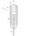
以下、図面を参照して本発明の一実施形態を説明する。図1は、本実施形態のファイバコリメータ1の一例を示す概略断面図である。本実施形態のファイバコリメータ1は、円筒状の筐体2、GRINレンズ3、光ファイバ4からなる。
GRINレンズ3と光ファイバ4とは融着接続されている。通常、GRINレンズ3と光ファイバ4との融着接続は、光ファイバ4の先端から2〜3mm程度に渡って被覆層14が剥離されて裸光ファイバ24が露出した状態で行われる。この裸光ファイバ24が露出した部分には、融着接続後、耐熱性に優れた接着剤5が被覆されている。この接着剤5としては、シリコン系接着剤などが使用できる。
【0013】
また、GRINレンズ3と筐体2は、筐体2の一方の端部側で低融点ガラス6により接合されている。この低融点ガラス6は、Pb,Bi,B,Nb,Ti,Zn,Fe等の酸化物を含む材料であり、軟化点が半田の融点よりも高いものである。
低融点ガラス6は、GRINレンズ3と筐体2との間の空間を気密封止するように設けられている。このような低融点ガラス6をGRINレンズ3と筐体2との間の空間に設ける方法としては、例えば特願2002−368311号に記載された方法を適用できる。
【0014】
光ファイバ4は、筐体2の他方の端部側より外部に引き出されている。この状態で、光ファイバ4と筐体2とは接着剤7により固定されている。この接着剤7は、光ファイバ4と筐体2との間の空間を気密封止するように設けられている。
筐体2は、その側壁に気体抜け用の貫通孔8が設けられたものであり、この貫通孔8を介して気体がファイバコリメータ1の内部と外部とを流通できるようになっている。この貫通孔8が気体抜け機構となる。
【0015】
本実施形態のファイバコリメータ1は、筐体2に気体抜け用の貫通孔8が設けられており、ファイバコリメータ1が加熱されて筐体2内の気体が膨張しても、前記貫通孔8から筐体2内の気体が筐体2の外方に流出するようになっている。これにより、ファイバコリメータ1が加熱されても、筐体2内の気体の圧力は上昇することが無く、外気とほぼ同じとなる。このため、従来のように筐体2内の気体の圧力上昇によりGRINレンズ3が筐体2から外れることがなく、半田を用いて、このファイバコリメータ1を光部品用筐体内に固定することができる。
【0016】
また、GRINレンズ3と筐体2とは、低融点ガラス6により接合されているため、例えば半田を溶融するために250℃以上に加熱しても低融点ガラス6は軟化することが無く、GRINレンズ3が筐体2から外れることがない。このように優れた熱安定性が得られる。
【0017】
また、従来のようにGRINレンズ3と光ファイバ4との間に空気層やスペーサが設けられておらず、GRINレンズ3と光ファイバ4とが直接融着接続されている。このGRINレンズ3と光ファイバ4は、共に石英ガラスから構成されているため熱膨張係数が同一であり、接続界面にて熱膨張による光軸の軸ズレが生じることが無く、温度変化による光学特性の変動を非常に小さく抑えることができる。
更に、GRINレンズ3と光ファイバ4とを融着接続後、光ファイバ4のうち裸光ファイバ24が露出した部分には、耐熱性に優れた接着剤5が被覆されており、これにより裸光ファイバ24が外気と直接接触することが無く、外気中の湿気により裸光ファイバ24の光学特性や機械強度が劣化することを防止できる。
【0018】
このような本実施形態のファイバコリメータ1を用いることによって、半田にてファイバコリメータ1を光部品用筐体に固定して光部品とすることができる。このため、ファイバコリメータ1と光部品用筐体間の隙間を完全に封止でき、容易に光部品内を気密封止できる。また、半田を用いた製造工程では、製造に係る装置も安価で、複雑な作業工程が無く、安価で簡便に光部品を製造できる。
【0019】
前記したように光部品内を気密封止できるため、ファイバコリメータ1が2つ対向配置した状態で半田にて光部品用筐体に固定された光部品は、光が伝播する空間に湿気などが侵入することをなくすることができ、光学特性の耐環境信頼性に優れた光部品が実現できる。
【0020】
[第2の実施形態]
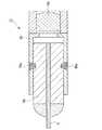
図2は、本実施形態のファイバコリメータ11の一例を示す概略断面図である。第2の実施形態が第1の実施形態と異なる点は、光ファイバ4と筐体12とを固定するための接着剤7によって、光ファイバ4と筐体12との間の空間が完全に封止されておらず、開口部9が設けられている点である。この開口部9が気体抜け機構となり、筐体12内の気体が筐体12の外方に流出するようになっている。
これにより、第1の実施形態と同様に、ファイバコリメータ11が加熱されても、筐体12内の気体の圧力は上昇することが無い。このため、従来のように筐体12内の気体の圧力上昇によりGRINレンズ3が筐体12から外れることがなく、半田を用いて、このファイバコリメータ11を光部品用筐体内に固定することができる。
【0021】
[第3の実施形態]
第3の実施形態が第2の実施形態と異なる点は、光ファイバ通し穴が設けられたゴム製のブーツが筐体12の他方の端部側に固定され、光ファイバ通し穴より光ファイバ4が外方に引き出されている点である。光ファイバ通し穴において、光ファイバ4はブーツに固定されておらず、光ファイバ通し穴と光ファイバ4との隙間から、ファイバコリメータ内の気体が外方に流出できるようになっている。
このため、ファイバコリメータが加熱されて筐体12内の気体が膨張しても、筐体12内の気体の圧力は上昇することが無いため、半田を用いて、このファイバコリメータを光部品用筐体内に固定することができる。
【0022】
[第4の実施形態]
本実施形態では、第1の実施形態のファイバコリメータを用いて、偏波保持型光部品を製造する方法を説明する。
ファイバコリメータは、光ファイバとして偏波保持光ファイバを使用する以外は、第1の実施形態と同一であるため詳細の説明は省略する。偏波保持型光部品としては、ファイバコリメータが2つ対向配置され、このファイバコリメータ間の空間を光が伝播できるようにしたものである。このような偏波保持型光部品では、2つのファイバコリメータの偏波軸Pを一致させる必要があり、ファイバコリメータの調芯工程が必要となる。
【0023】
図3は、本実施形態における調芯工程を示す図である。2つのファイバコリメータ21,31を対向配置し、一方のファイバコリメータ21を固定し、他方のファイバコリメータ31を回転させて、最も損失の小さい回転角(最小損失角度)を探してψ角調芯を行う。
このとき回転角は、双方のファイバコリメータ21,31に設けられた貫通孔28,38の相対位置として求める。例えば貫通孔38が、貫通孔28の長手方向に対して一致する位置28’にあるときを回転角が0°の位置とし、この位置28’から他方のファイバコリメータ31を回転させた角度αを回転角としてもよい。
このように、ψ角調芯した後、最小損失角度を貫通孔28,38の相対位置として見出す。この後の工程では、2つのファイバコリメータ21,31の貫通孔28,38の相対位置を前記最小損失角度に合わせるだけでψ角調芯を行う。
【0024】
次に、円筒状の光部品用筐体内にファイバコリメータ21,31を実装する。まず、光部品用筐体内に2つのファイバコリメータ21,31を対向配置する。そして、2つのファイバコリメータ21,31の貫通孔28,38の相対位置を前記最小損失角度に合わせる。この状態でファイバコリメータ21,31を仮固定し、半田を用いてファイバコリメータ21,31を光部品用筐体に固定する。このときファイバコリメータ21,31と光部品用筐体との隙間が、半田によって完全に気密封止された状態とする。
【0025】
本実施形態では、最小損失角度を貫通孔の相対位置として見出すことによって、この後の工程では、2つのファイバコリメータ21,31の貫通孔28,38の相対位置を前記最小損失角度に合わせるだけで容易にψ角調芯を行うことができる。このため、調芯に係る作業が簡略化でき、安価に偏波保持型光部品を製造することができる。
例えばψ角調芯の後に、θ角、φ角の調芯なども行う場合、θ角、φ角の調芯の後、再度ψ角のずれを補正するとき、貫通孔28,38の相対位置を前記最小損失角度に合わせるだけで再びψ角調芯が行える。このように、複数回ψ角調芯を行う場合も、貫通孔28,38の相対位置を前記最小損失角度に合わせるだけでよく、調芯に係る作業が大幅に簡略でき、安価に偏波保持型光部品を製造することができる。
【0026】
なお、本実施形態は、偏波保持型光部品に限定されず、ファイバコリメータが2つ対向配置された光部品に適用できる。例えばψ角調芯を高精度に行い、低損失の光部品を歩留まり良く製造できるようにする場合に、本実施形態は好ましく適用できる。
【0027】
【発明の効果】
以上、詳細に説明したように、請求項1乃至7に係る発明によれば、気体抜け機構が設けられており、例えばファイバコリメータが加熱された場合のように、ファイバコリメータ内の気体が膨張しても、気体抜け機構から気体がファイバコリメータの外方に流出できるようになっている。これにより、ファイバコリメータが加熱されても、ファイバコリメータ内の気体の圧力上昇によりレンズが筐体から外れることがなく、半田を用いて、このファイバコリメータを光部品用筐体内に固定することができる。
【0028】
特に請求項4及び5に係る発明によれば、GRINレンズと筐体とは、低融点ガラスのように軟化点が半田の融点よりも高い材料により接合されているため、例えば半田を溶融するために250℃以上に加熱しても低融点ガラスは軟化することが無く、GRINレンズが筐体から外れることがない。このように優れた熱安定性が得られる。
【0029】
更に請求項6に係る発明によれば、レンズと光ファイバとが直接融着接続されることによって、接続界面にて熱膨張による光軸の軸ズレが生じることが無く、温度変化による光学特性の変動を非常に小さく抑えることができる。これに加えて,請求項7に係る発明によれば、裸光ファイバが露出した部分に、耐熱性に優れた接着剤が被覆されたことによって、裸光ファイバが外気と直接接触することが無く、外気中の湿気により裸光ファイバの光学特性や機械強度が劣化することを防止できる。
【0030】
また、請求項8に係る発明では、本発明のファイバコリメータを使用し、このファイバコリメータが半田を用いて光部品用筐体内に固定されたことによって、光部品の光路を完全に封止でき、これにより光が伝播する空間に湿気などが侵入することをなくすることができ、光学特性の耐環境信頼性に優れた光部品が実現できる。
【0031】
また、請求項9に係る発明によれば、本発明のファイバコリメータを使用することによって、半田にてファイバコリメータを光部品用筐体に固定して光部品とすることができる。このため、ファイバコリメータと光部品用筐体間の隙間を完全に封止でき、容易に光部品の光路部分を気密封止できる。また、半田を用いた製造工程では、製造に係る装置も安価で、複雑な作業工程が無く、安価で簡便に光部品を製造できる。
【0032】
これに加えて、請求項10に係る発明によれば、最小損失角度を貫通孔の相対位置として見出すことによって、この後の工程では、2つのファイバコリメータの貫通孔の相対位置を前記最小損失角度に合わせるだけで容易にψ角調芯を行うことができる。このため、調芯に係る作業が簡略化でき、安価に偏波保持型光部品等の光部品を製造することができる。
【図面の簡単な説明】
【図1】 第1の実施形態のファイバコリメータを示す概略断面図である。である。
【図2】 第2の実施形態のファイバコリメータを示す概略断面図である。である。
【図3】 第4の実施形態における調芯工程を示す図である。
【図4】 従来のファイバコリメータの一例を示す概略断面図である。
【図5】 従来のファイバコリメータの他の一例を示す概略断面図である。
【符号の説明】
1,11,21,31‥‥ファイバコリメータ、2,12‥‥筐体、3‥‥レンズ、4‥‥光ファイバ、5‥‥接着剤、6‥‥低融点ガラス、8,28,38‥‥貫通孔、9‥‥開口部、14‥‥光ファイバの被覆層、24‥‥裸光ファイバ[0001]
BACKGROUND OF THE INVENTION
The present invention relates to a fiber collimator that can be mounted on an optical component casing using solder, an optical component using the same, and a method of manufacturing the optical component.
[0002]
[Prior art]
The fiber collimator has an optical fiber and a lens, and is used for an optical component having an optical circuit portion that requires switching from optical fiber propagation to spatial propagation. For example, by arranging two fiber collimators facing each other, allowing light to propagate through the space between the fiber collimators, and arranging optical parts such as a filter in the space where this light propagates, An optical demultiplexer, an optical switch, etc. are formed. An optical component in which two such fiber collimators are arranged to face each other is normally manufactured by fixing the fiber collimator to each of two open end portions of a cylindrical optical component casing.
[0003]
In the optical component using the fiber collimator, it is necessary to prevent moisture and the like from entering the space where light propagates, and the optical component must be hermetically sealed.
For example, in the case of an optical component in which two fiber collimators are arranged opposite to each other, the fiber collimator is fixed in the optical component housing using solder, thereby completely sealing the gap between the fiber collimator and the housing. It is possible to prevent outside air from entering the optical component. For this reason, it is possible to realize an optical component having excellent environmental resistance and stable optical characteristics.
[0004]
However, when fixing the fiber collimator using solder, it is necessary to heat to about 250 ° C. in order to melt the solder, and heat is transferred to the fiber collimator. For this reason, in the conventional fiber collimator, the following problems occur.
FIG. 4 is a schematic sectional view showing an example of a
In the case where the
[0005]
Therefore, by filling the gap between the
However, an adhesive is present in the light propagation path, and the optical characteristics are deteriorated due to an increase in light loss due to bubbles in the adhesive and a decrease in light resistance power characteristics due to the adhesive. Furthermore, since the adhesive is likely to deteriorate under conditions of high temperature and humidity, the environmental resistance is poor.
As described above, the conventional configuration shown in FIG. 4 cannot realize the
[0006]
It is also conceivable to use a fiber collimator with excellent heat resistance so that it can be fixed in the optical component casing with solder. As such a fiber collimator, for example, a capillary and a lens are connected via a transparent spacer, and the vicinity of the portion where the optical fiber at the tip of the capillary passes is made of a material having a low thermal expansion coefficient similar to that of the optical fiber. It has been proposed (see Patent Document 2).
Because the thermal expansion coefficients of the tip of the capillary, the optical fiber, and the spacer are almost the same, there is almost no thermal stress due to the difference in the thermal expansion coefficient, and adhesion between the capillary and the spacer or between the capillary and the optical fiber at high temperatures No peeling due to thermal stress on the surface.
However, this fiber collimator can obtain excellent thermal stability up to about 180 ° C., but when heated to 250 ° C. or higher in order to melt the solder, the fiber collimator is similar to the fiber collimator shown in FIG. The pressure in the collimator increases, and this pressure may cause the lens or capillary to come off the casing.
[0007]
FIG. 5 is a schematic cross-sectional view showing another example of a
When such a
However, in the method of connecting by welding, the apparatus for manufacturing is very expensive, and the manufacturing cost becomes high. In addition, the
[0008]
As described above, the conventional fiber collimator cannot be mounted on the optical component casing by soldering or has a problem such as deterioration of the adhesive under high temperature and high humidity conditions. The optical parts manufactured using such a material are not hermetically sealed and are inferior in environmental resistance reliability of optical characteristics. In addition, there are problems such as insufficient optical characteristics such as light-resistant power characteristics and light loss, and high manufacturing costs.
[0009]
[Patent Document 1]
JP 2002-196180 A [Patent Document 2]
Japanese Patent No. 2509582 [Patent Document 3]
Japanese Patent Laid-Open No. 7-151934
[Problems to be solved by the invention]
The present invention has been made in view of the above circumstances. That is, a fiber collimator that can be mounted on an optical component casing using solder and has excellent optical characteristics, and an optical component that is mounted by solder using this fiber collimator and has excellent environmental resistance, and the optical component. An object of the present invention is to provide a method that is inexpensive and can be easily manufactured.
[0011]
[Means for Solving the Problems]
The invention according to
The invention according to
The invention according to claim3, wherein the softening point is higher material than the melting point of the solder, a fiber collimator of
The invention according to claim4 is the fiber collimator according to any one of
According to afifth aspect of the present invention, after the coating layer around the tip of the optical fiber is peeled off and the bare optical fiber is exposed and fusion bonded to the lens, the bare optical fiber is coated with an adhesive. The fiber collimator according to claim4 , wherein the fiber collimator is an optical fiber.
An invention according to
[0012]
DETAILED DESCRIPTION OF THE INVENTION
[First Embodiment]
Hereinafter, an embodiment of the present invention will be described with reference to the drawings. FIG. 1 is a schematic cross-sectional view showing an example of the
The GRIN lens 3 and the optical fiber 4 are fusion-connected. Usually, the fusion splicing of the GRIN lens 3 and the optical fiber 4 is performed in a state in which the
[0013]
Further, the GRIN lens 3 and the
The low
[0014]
The optical fiber 4 is drawn out from the other end side of the
The
[0015]
The
[0016]
In addition, since the GRIN lens 3 and the
[0017]
Further, unlike the prior art, no air layer or spacer is provided between the GRIN lens 3 and the optical fiber 4, and the GRIN lens 3 and the optical fiber 4 are directly fused and connected. Since both the GRIN lens 3 and the optical fiber 4 are made of quartz glass, they have the same thermal expansion coefficient, and there is no optical axis misalignment due to thermal expansion at the connection interface, and optical characteristics due to temperature changes. Fluctuations can be kept very small.
Further, after the GRIN lens 3 and the optical fiber 4 are fused and connected, the exposed portion of the bare
[0018]
By using the
[0019]
As described above, since the inside of the optical component can be hermetically sealed, the optical component fixed to the optical component casing with the solder in a state where the two
[0020]
[Second Embodiment]
FIG. 2 is a schematic cross-sectional view showing an example of the
Thereby, as in the first embodiment, even if the
[0021]
[Third Embodiment]
The third embodiment differs from the second embodiment in that a rubber boot provided with an optical fiber through hole is fixed to the other end side of the
For this reason, even if the gas in the
[0022]
[Fourth Embodiment]
In the present embodiment, a method of manufacturing a polarization maintaining optical component using the fiber collimator of the first embodiment will be described.
Since the fiber collimator is the same as that of the first embodiment except that a polarization maintaining optical fiber is used as the optical fiber, detailed description thereof is omitted. As the polarization maintaining optical component, two fiber collimators are arranged opposite to each other so that light can propagate through the space between the fiber collimators. In such a polarization maintaining optical component, it is necessary to match the polarization axes P of the two fiber collimators, and a fiber collimator alignment process is required.
[0023]
FIG. 3 is a diagram illustrating an alignment process in the present embodiment. Two
At this time, the rotation angle is obtained as a relative position of the through
Thus, after the ψ angle alignment, the minimum loss angle is found as the relative position of the through
[0024]
Next, the
[0025]
In this embodiment, by finding the minimum loss angle as the relative position of the through hole, in the subsequent steps, the relative positions of the through
For example, when θ angle and φ angle alignment is also performed after the ψ angle alignment, the relative positions of the through
[0026]
In addition, this embodiment is not limited to a polarization maintaining optical component, but can be applied to an optical component in which two fiber collimators are arranged to face each other. For example, this embodiment can be preferably applied to the case where the ψ angle alignment is performed with high accuracy so that a low-loss optical component can be manufactured with a high yield.
[0027]
【The invention's effect】
As described above in detail, according to the inventions according to
[0028]
In particular, according to the inventions according to
[0029]
According to the sixth aspect of the present invention, since the lens and the optical fiber are directly fusion-bonded, there is no optical axis misalignment due to thermal expansion at the connection interface, and the optical characteristics due to temperature change are reduced. The fluctuation can be kept very small. In addition, according to the invention of claim 7, the exposed portion of the bare optical fiber is coated with an adhesive having excellent heat resistance, so that the bare optical fiber is not in direct contact with the outside air. The optical properties and mechanical strength of the bare optical fiber can be prevented from deteriorating due to moisture in the outside air.
[0030]
Further, in the invention according to claim 8, by using the fiber collimator of the present invention, and the fiber collimator is fixed in the optical component casing using solder, the optical path of the optical component can be completely sealed, As a result, moisture or the like can be prevented from entering the space in which light propagates, and an optical component having excellent optical characteristics and environmental resistance can be realized.
[0031]
According to the invention of
[0032]
In addition, according to the invention of claim 10, by finding the minimum loss angle as the relative position of the through-hole, in the subsequent step, the relative position of the through-holes of the two fiber collimators is set to the minimum loss angle. Ψ angle alignment can be easily performed only by adjusting to. For this reason, the operation | work regarding alignment can be simplified and optical components, such as a polarization-maintaining optical component, can be manufactured cheaply.
[Brief description of the drawings]
FIG. 1 is a schematic cross-sectional view showing a fiber collimator according to a first embodiment. It is.
FIG. 2 is a schematic cross-sectional view showing a fiber collimator according to a second embodiment. It is.
FIG. 3 is a diagram showing an alignment process in a fourth embodiment.
FIG. 4 is a schematic cross-sectional view showing an example of a conventional fiber collimator.
FIG. 5 is a schematic cross-sectional view showing another example of a conventional fiber collimator.
[Explanation of symbols]
1, 11, 21, 31 ... Fiber collimator, 2, 12 ... Housing, 3 ... Lens, 4 ... Optical fiber, 5 ... Adhesive, 6 ... Low melting point glass, 8, 28, 38 ... ... through hole, 9 ... opening, 14 ... coating layer of optical fiber, 24 ... bare optical fiber
Claims (6)
Translated fromJapanese気体抜け機構が設けられ、ファイバコリメータ内の気体が外方に流出できるようにし、
前記筐体が開口部を有し、光ファイバ通し穴が設けられたブーツが筐体の前記開口部側に固定され、光ファイバ通し穴より光ファイバが外方に引き出され、
前記気体抜け機構が光ファイバ通し穴と光ファイバとの隙間であり、該隙間から、ファイバコリメータ内の気体が外方に流出できるようにしたことを特徴とするファイバコリメータ。In a fiber collimator that includes a lens to which an optical fiber is connected and a housing, and the lens is fixed to the housing.
A gas escape mechanism is provided so that the gas in the fiber collimator can flow outward.
The housing has an opening, a boot provided with an optical fiber through hole is fixed to the opening side of the housing, and the optical fiber is drawn outward from the optical fiber through hole,
The fiber collimator is characterized in that the gas escape mechanism is a gap between the optical fiber through hole and the optical fiber, and the gas in the fiber collimator can flow out from the gap.
Priority Applications (1)
| Application Number | Priority Date | Filing Date | Title |
|---|---|---|---|
| JP2003058630AJP4090915B2 (en) | 2003-03-05 | 2003-03-05 | Fiber collimator, optical component, and method for manufacturing optical component |
Applications Claiming Priority (1)
| Application Number | Priority Date | Filing Date | Title |
|---|---|---|---|
| JP2003058630AJP4090915B2 (en) | 2003-03-05 | 2003-03-05 | Fiber collimator, optical component, and method for manufacturing optical component |
Publications (2)
| Publication Number | Publication Date |
|---|---|
| JP2004271619A JP2004271619A (en) | 2004-09-30 |
| JP4090915B2true JP4090915B2 (en) | 2008-05-28 |
Family
ID=33121693
Family Applications (1)
| Application Number | Title | Priority Date | Filing Date |
|---|---|---|---|
| JP2003058630AExpired - Fee RelatedJP4090915B2 (en) | 2003-03-05 | 2003-03-05 | Fiber collimator, optical component, and method for manufacturing optical component |
Country Status (1)
| Country | Link |
|---|---|
| JP (1) | JP4090915B2 (en) |
Cited By (1)
| Publication number | Priority date | Publication date | Assignee | Title |
|---|---|---|---|---|
| US8078360B2 (en) | 2007-08-08 | 2011-12-13 | Honda Motor Co., Ltd. | Control apparatus of a variable damping force damper |
Families Citing this family (2)
| Publication number | Priority date | Publication date | Assignee | Title |
|---|---|---|---|---|
| CN105759462B (en)* | 2016-04-18 | 2018-10-16 | 北京大学 | A kind of adjustable optic fibre colimated light system |
| CN114678759A (en)* | 2022-03-23 | 2022-06-28 | 深圳市欧凌镭射科技有限公司 | Fiber-coupled crystal structures and gain devices |
- 2003
- 2003-03-05JPJP2003058630Apatent/JP4090915B2/ennot_activeExpired - Fee Related
Cited By (1)
| Publication number | Priority date | Publication date | Assignee | Title |
|---|---|---|---|---|
| US8078360B2 (en) | 2007-08-08 | 2011-12-13 | Honda Motor Co., Ltd. | Control apparatus of a variable damping force damper |
Also Published As
| Publication number | Publication date |
|---|---|
| JP2004271619A (en) | 2004-09-30 |
Similar Documents
| Publication | Publication Date | Title |
|---|---|---|
| US6074104A (en) | Method for hermetically sealing optical fiber introducing section and hermetically sealed structure | |
| JP2616668B2 (en) | Hermetically sealed structure of optical fiber introduction section | |
| US20030099453A1 (en) | Hermetic fiber ferrule and feedthrough | |
| JP2524463B2 (en) | Airtight sealing method for optical fiber introduction part | |
| JP4090915B2 (en) | Fiber collimator, optical component, and method for manufacturing optical component | |
| CN101226317A (en) | Small Optical Package with Multiple Optically Aligned Soldered Components | |
| US20030190135A1 (en) | Hermetic waveguide seals and method of making them | |
| JP2007271674A (en) | Optical device | |
| JP3370264B2 (en) | Optical module | |
| JPH0267508A (en) | Optical fiber fixing method | |
| US20020179683A1 (en) | Hermetic optical fiber seal | |
| JP3078490B2 (en) | Method of butt-joining lightwave paths and connecting arrays of lightwave paths to each other | |
| JP2697692B2 (en) | Pigtails and how to make them | |
| JP3993083B2 (en) | Fiber collimator and manufacturing method thereof | |
| JP3149542B2 (en) | Hermetically sealed optical fiber terminal | |
| JPH0735953A (en) | Structure of optical element casing having mechanism for drawing out and sealing optical fiber and its production | |
| JP2005024928A (en) | Optical parts | |
| JP2800565B2 (en) | Hermetically sealed optical fiber terminal | |
| JP2008096843A (en) | Optical waveguide structure, optical receptacle using the same, and method of manufacturing optical waveguide structure | |
| JPH09223806A (en) | Optical semiconductor module | |
| JP3076127B2 (en) | Optical fiber terminal for hermetic sealing | |
| JPH0375608A (en) | Packaging method for optical waveguide parts | |
| JP3293958B2 (en) | Optical element housing structure having optical fiber draw-out sealing mechanism and method of manufacturing the same | |
| JP2004317840A (en) | Optical device and its manufacturing method | |
| JP3301197B2 (en) | Parallel transmission module and manufacturing method thereof |
Legal Events
| Date | Code | Title | Description |
|---|---|---|---|
| A621 | Written request for application examination | Free format text:JAPANESE INTERMEDIATE CODE: A621 Effective date:20051205 | |
| A977 | Report on retrieval | Free format text:JAPANESE INTERMEDIATE CODE: A971007 Effective date:20070606 | |
| A131 | Notification of reasons for refusal | Free format text:JAPANESE INTERMEDIATE CODE: A131 Effective date:20070710 | |
| A521 | Written amendment | Free format text:JAPANESE INTERMEDIATE CODE: A523 Effective date:20070903 | |
| A131 | Notification of reasons for refusal | Free format text:JAPANESE INTERMEDIATE CODE: A131 Effective date:20071002 | |
| A521 | Written amendment | Free format text:JAPANESE INTERMEDIATE CODE: A523 Effective date:20071130 | |
| TRDD | Decision of grant or rejection written | ||
| A01 | Written decision to grant a patent or to grant a registration (utility model) | Free format text:JAPANESE INTERMEDIATE CODE: A01 Effective date:20080219 | |
| A61 | First payment of annual fees (during grant procedure) | Free format text:JAPANESE INTERMEDIATE CODE: A61 Effective date:20080227 | |
| FPAY | Renewal fee payment (event date is renewal date of database) | Free format text:PAYMENT UNTIL: 20110307 Year of fee payment:3 | |
| FPAY | Renewal fee payment (event date is renewal date of database) | Free format text:PAYMENT UNTIL: 20110307 Year of fee payment:3 | |
| FPAY | Renewal fee payment (event date is renewal date of database) | Free format text:PAYMENT UNTIL: 20120307 Year of fee payment:4 | |
| FPAY | Renewal fee payment (event date is renewal date of database) | Free format text:PAYMENT UNTIL: 20120307 Year of fee payment:4 | |
| FPAY | Renewal fee payment (event date is renewal date of database) | Free format text:PAYMENT UNTIL: 20130307 Year of fee payment:5 | |
| FPAY | Renewal fee payment (event date is renewal date of database) | Free format text:PAYMENT UNTIL: 20130307 Year of fee payment:5 | |
| FPAY | Renewal fee payment (event date is renewal date of database) | Free format text:PAYMENT UNTIL: 20140307 Year of fee payment:6 | |
| R250 | Receipt of annual fees | Free format text:JAPANESE INTERMEDIATE CODE: R250 | |
| R250 | Receipt of annual fees | Free format text:JAPANESE INTERMEDIATE CODE: R250 | |
| LAPS | Cancellation because of no payment of annual fees |