JP4088058B2 - X-ray computed tomography system - Google Patents
X-ray computed tomography systemDownload PDFInfo
- Publication number
- JP4088058B2 JP4088058B2JP2001320927AJP2001320927AJP4088058B2JP 4088058 B2JP4088058 B2JP 4088058B2JP 2001320927 AJP2001320927 AJP 2001320927AJP 2001320927 AJP2001320927 AJP 2001320927AJP 4088058 B2JP4088058 B2JP 4088058B2
- Authority
- JP
- Japan
- Prior art keywords
- ray
- ray tube
- opening
- rays
- collimator
- Prior art date
- Legal status (The legal status is an assumption and is not a legal conclusion. Google has not performed a legal analysis and makes no representation as to the accuracy of the status listed.)
- Expired - Fee Related
Links
Images


Classifications
- A—HUMAN NECESSITIES
- A61—MEDICAL OR VETERINARY SCIENCE; HYGIENE
- A61B—DIAGNOSIS; SURGERY; IDENTIFICATION
- A61B6/00—Apparatus or devices for radiation diagnosis; Apparatus or devices for radiation diagnosis combined with radiation therapy equipment
- A61B6/48—Diagnostic techniques
- A61B6/488—Diagnostic techniques involving pre-scan acquisition
- A—HUMAN NECESSITIES
- A61—MEDICAL OR VETERINARY SCIENCE; HYGIENE
- A61B—DIAGNOSIS; SURGERY; IDENTIFICATION
- A61B6/00—Apparatus or devices for radiation diagnosis; Apparatus or devices for radiation diagnosis combined with radiation therapy equipment
- A61B6/02—Arrangements for diagnosis sequentially in different planes; Stereoscopic radiation diagnosis
- A61B6/03—Computed tomography [CT]
- A61B6/032—Transmission computed tomography [CT]
- A—HUMAN NECESSITIES
- A61—MEDICAL OR VETERINARY SCIENCE; HYGIENE
- A61N—ELECTROTHERAPY; MAGNETOTHERAPY; RADIATION THERAPY; ULTRASOUND THERAPY
- A61N5/00—Radiation therapy
- A61N5/10—X-ray therapy; Gamma-ray therapy; Particle-irradiation therapy
- A61N5/1048—Monitoring, verifying, controlling systems and methods
- A61N5/1049—Monitoring, verifying, controlling systems and methods for verifying the position of the patient with respect to the radiation beam
- A—HUMAN NECESSITIES
- A61—MEDICAL OR VETERINARY SCIENCE; HYGIENE
- A61B—DIAGNOSIS; SURGERY; IDENTIFICATION
- A61B6/00—Apparatus or devices for radiation diagnosis; Apparatus or devices for radiation diagnosis combined with radiation therapy equipment
- A61B6/06—Diaphragms
- A—HUMAN NECESSITIES
- A61—MEDICAL OR VETERINARY SCIENCE; HYGIENE
- A61B—DIAGNOSIS; SURGERY; IDENTIFICATION
- A61B6/00—Apparatus or devices for radiation diagnosis; Apparatus or devices for radiation diagnosis combined with radiation therapy equipment
- A61B6/44—Constructional features of apparatus for radiation diagnosis
- A61B6/4429—Constructional features of apparatus for radiation diagnosis related to the mounting of source units and detector units
- A—HUMAN NECESSITIES
- A61—MEDICAL OR VETERINARY SCIENCE; HYGIENE
- A61N—ELECTROTHERAPY; MAGNETOTHERAPY; RADIATION THERAPY; ULTRASOUND THERAPY
- A61N5/00—Radiation therapy
- A61N5/10—X-ray therapy; Gamma-ray therapy; Particle-irradiation therapy
- A61N5/1048—Monitoring, verifying, controlling systems and methods
- A61N5/1049—Monitoring, verifying, controlling systems and methods for verifying the position of the patient with respect to the radiation beam
- A61N2005/1061—Monitoring, verifying, controlling systems and methods for verifying the position of the patient with respect to the radiation beam using an x-ray imaging system having a separate imaging source
Landscapes
- Health & Medical Sciences (AREA)
- Life Sciences & Earth Sciences (AREA)
- Engineering & Computer Science (AREA)
- Medical Informatics (AREA)
- Biomedical Technology (AREA)
- Animal Behavior & Ethology (AREA)
- Veterinary Medicine (AREA)
- Nuclear Medicine, Radiotherapy & Molecular Imaging (AREA)
- Public Health (AREA)
- Pathology (AREA)
- Radiology & Medical Imaging (AREA)
- General Health & Medical Sciences (AREA)
- Heart & Thoracic Surgery (AREA)
- Molecular Biology (AREA)
- Surgery (AREA)
- Physics & Mathematics (AREA)
- Biophysics (AREA)
- Optics & Photonics (AREA)
- High Energy & Nuclear Physics (AREA)
- Pulmonology (AREA)
- Theoretical Computer Science (AREA)
- Apparatus For Radiation Diagnosis (AREA)
- Radiation-Therapy Devices (AREA)
Description
Translated fromJapanese【0001】
【発明の属する技術分野】
本発明は、多管球型のX線コンピュータ断層撮影装置に関する。
【0002】
【従来の技術】
従来より、X線を被検体に透過させ、その透過データをコンピュータ処理することにより画像を再構成するX線コンピュータト断層撮影装置が知られている。こうして得られた画像により、治療対象の位置、大きさ及び病変の程度等の医学的な知見を得、それに基づいて治療計画を立てる、つまり放射線の照射範囲、照射位置、さらに照射線量等を設定する。こうして、放射線を治療領域にのみ正確に照射することによって、周囲の健常組織へのダメージを最小限に抑えて、治療対象のみを放射線で治療するようにしている。
【0003】
しかしながら、従来では、治療対象の位置及び大きさ等を知見を得るためのX線コンピュータ断層撮影装置と放射線治療装置との2つの装置が必要となり、大きな設置面積が必要であるとともに、多大なコストがかかる。そればかりでなく、別個の装置であるX線コンピュータ断層撮影装置で位置や大きさ等を求めてから、患者を、通常は別室の放射線治療装置に移送し、そこで改めて位置設定を行うため、位置決め精度が低下するという問題があった。
【0004】
【発明が解決しようとする課題】
本発明の目的は、放射線治療の位置決め精度を向上し得るX線コンピュータ断層撮影装置を提供することにある。
【0005】
【課題を解決するための手段】
本発明の第1局面に係るX線コンピュータ断層撮影装置は、被検体に照射するためのX線を発生する第1X線管と、前記被検体を透過したX線を検出する第1X線検出器と、前記被検体の治療対象に照射するためのX線を発生する第2X線管と、前記第2X線管からのX線を絞るための幅及び位置が可変の開口を有する第2X線コリメータと、前記第1X線管装置、前記第1X線検出器及び前記第2X線管装置を前記被検体回りに回転する回転機構と、前記第1X線管装置及び前記第1X線検出器の回転と並行して、前記X線検出器で検出されたデータに基づく画像の再構成を繰り返す再構成ユニットと、前記画像から前記治療対象の領域を繰り返し抽出する画像処理部と、前記抽出された前記治療対象の領域に基づいて前記X線コリメータの開口の中心位置と幅との少なくとも一方を、前記第2X線管の回転に伴って動的に変化させる制御部とを具備し、前記第2X線管から前記治療対象へのX線照射と並行して、前記第1X線管装置及び前記第1X線検出器によるデータの検出、前記画像の再構成、前記画像からの前記治療対象の領域の抽出、前記X線コリメータの開口の制御が即時的に実行される。
【0006】
【発明の実施の形態】
以下、図面を参照して本発明によるX線コンピュータ断層撮影装置(X線CT装置)を好ましい実施形態により説明する。なお、X線コンピュータ断層撮影装置のスキャン方式としては、X線管とX線検出器とが1体として被検体の周囲を回転するローテート/ローテートタイプ、リング状にアレイされた多数の検出素子が固定され、X線管のみが被検体の周囲を回転するステーショナリ/ローテートタイプ等様々なタイプがあり、いずれのタイプでも本発明を適用可能であるが、ここではローテート/ローテートタイプを例に説明する。また、1枚の断層像データを再構成するには、被検体の周囲1周、約360°分の投影データの1セットが、またハーフスキャン法でも180°+ファン角分の投影データが必要とされる。ここでは、前者の例で説明する。なお、投影データとは、X線パス上の組織等の減弱係数(又は吸収係数)の通過距離に関する積分データとして定義される。
【0007】
図1に、本実施形態に係るX線コンピュータ断層撮影装置の主要部の構成を示している。本実施形態のX線コンピュータ断層撮影装置は、スキャンガントリ1とコンピュータ装置2と図示しない寝台とから構成される。スキャンガントリ1は、被検体に関する投影データを収集するための構成要素であり、その投影データはコンピュータ装置2に取り込まれ、画像再構成等の処理に供される。被検体は、寝台の天板に載置された状態でスキャンガントリ1の撮影領域内に挿入される。
【0008】
コンピュータ装置2は、中央制御ユニット21と、それに対してデータ/制御バス22を介して接続された前処理部23、画像再構成ユニット24、画像表示ユニット25及び画像処理部26から構成される。
【0009】
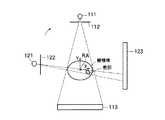
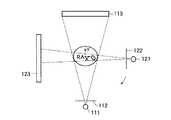
スキャンガントリ1は、多管球型であり、つまり円環状の回転架台に、X線管装置とX線検出器とのペアが複数搭載されている。ここでは、2管球型として説明する。第1ペア11は、第1X線管装置110と、それに対向する多チャンネル型の第1X線検出器113とが回転架台に搭載されている。第2ペア12は、第2X線管装置120と、それに対向する多チャンネル型の第2X線検出器123とが、その中心軸が第1ペア11の中心軸と回転軸RAで所定角度(ここでは90°と仮定する)交差する位置関係で回転架台に搭載されている。
【0010】
第1X線管装置110は、第1X線管球111と、第1X線管球111と被検体との間に配置される、具体的には第1X線管球111のX線放射窓の直前に取り付けられる第1X線絞り装置120等の周辺要素とから構成される。この第1X線絞り装置120は、第1X線管球111から放射されるX線の広がり角(ファン角ともいう)を制限するための装置であり、複数の可動式遮蔽板と、それらを個々に移動する駆動部とを備えている。複数の可動式遮蔽板各々の位置を制御することにより、開口幅および開口位置を任意に調整することができるようになっている。
【0011】
第2X線管装置120も同様に、第2X線管球121と、第2X線絞り装置122等の周辺要素とから構成される。また、第2X線絞り装置122も、第1X線絞り装置112と同様に、第2X線管球121から放射されるX線の広がり角(ファン角)を制限するための装置であり、複数の可動式遮蔽板と、それらを個々に移動する駆動部とを備え、複数の可動式遮蔽板各々の位置を制御することにより、開口幅および開口位置を任意に調整することができるようになっている。ただし、第2X線絞り装置122はその開口幅に関する機構上の制約が、第1X線絞り装置112のそれよりも緩和されている。具体的には、第2X線絞り装置122の開口下限(最小の開口幅)が、第1X線絞り装置112の開口下限よりも、狭く構成されている。なお、第2X線絞り装置122の開口上限(最大の開口幅)に関しては、第1X線絞り装置112の開口上限と略同じに構成されている。それにより、第2X線絞り装置122は、X線を被検体の断面全域をカバーするファン角に広げること、及びX線を被検体の断面内の比較的小さい治療対象(患部)に対して限定的に照射する程度にファン角に狭く設定することが可能である。
【0012】
第2X線管装置120は、Zシフト機構15に支持されている。Zシフト機構15は、図2に示すように、回転軸RA(Z軸に同じ)と平行又は略平行な向きに、第2X線管装置120を移動可能に支持するために必要な構造及び電動駆動部を装備している。このZシフト機構15による第2X線管装置120の移動は、架台制御部14の制御のもとにある。なお、典型的には、第1X線管装置110から照射されるX線束の中心軸は、回転軸RAに直交するように、第1X線管装置110のZ位置が設計され、その結果、第1X線管装置110から照射されるX線束は架台回転に伴ってその回転軸RAに直交する面(スキャン面)内で移動する。Zシフト機構15が第2X線管装置120をシフトしないとき、第2X線管装置120から照射されるX線束は架台回転に伴って上記と同じスキャン面内を移動するが、Zシフト機構15が第2X線管装置120をΔDの距離をシフトするとき、第2X線管装置120から照射されるX線束の中心軸は回転軸RAに対して斜めに交差するので、そのX線中心軸が架台回転に伴って描く形状としてはΔDを高さとする2つの円錐を頂点で結合した鼓形状になる。
【0013】
図1に戻る。X線制御部13は、管電圧及びフィラメント電流(フィラメント電流により管電流が制御される)を第1、第2X線管球111,121に対して個別に印加及び供給することができるように、第1X線管球111と第2X線管球121とにそれぞれ対応する2系統の高電圧発生器を装備している。第1X線管球111に対応する高電圧発生器は、イメージング用のX線条件のもとで第1X線管球111に電力を供給する。例えば、この高電圧発生器は、第1X線管球111に対して、管電圧が150kV以下、管電流が300mA以下の駆動能力を持っている。一方、第2X線管球121に対応する高電圧発生器は、イメージング用のX線条件よりも過酷な治療用のX線条件で第1X線管球111に電力を供給することが可能な高出力型が採用されている。例えば、この高電圧発生器は、第2X線管球121に対して、管電圧が150kV以上、管電流が300mA以上の駆動能力を持っている。
【0014】
これら2系統の高電圧発生器から第1、第2X線管球111、121に印加される管電圧及び管電流制御用のフィラメント電流は、架台制御部14の制御のもとにある。このX線制御部13に対する制御とともに、架台制御部14は、第1、第2X線絞り装置112、122それぞれの開口幅および開口位置、さらには回転架台の回転、天板のスライド等スキャンに関わる全てのオペレーション制御を担当する。
【0015】
第1、第2X線検出器113、123の出力は、それぞれデータ収集部114、124、図示しないが連続回転を可能にするスリップリング及び前処理部23を介して投影データとして再構成ユニット24に供給され、そこで断層像データの再構成のために用いられる。この断層像データは、画像表示ユニット25に表示されるとともに、特に第1ペア11を使って取得した断層像データは画像処理部26に送られ、そこで治療対象(患部)の領域の輪郭抽出に供される。
【0016】
上述したように、第2X線管球121に対応する高電圧発生器に高出力型を採用し、また第2X線絞り装置122にその開口下限が狭いものを採用したことにより、X線コンピュータ断層撮影装置に断層撮影とともに、放射線治療を兼用させることが可能になる。それにより断層像撮影、放射線治療時の位置決め、そして実際に放射線治療に至るまで、同じX線コンピュータ断層撮影装置一台でまかなうことができ、従って患者の物理的な移送が不要になり、位置決め精度の向上を図ることができる。
【0017】
しかも、多管球型を採用しているので、一方のペア12で放射線治療を実行しながら、それと並行して他方のペア11でイメージングのためのスキャン、つまりイメージング用X線条件でX線の曝射及び透過X線の検出を行って、即時的に断層像を観察し、またその断層像から体動等に伴う患部の移動に対して治療X線の照射位置を刻々と修正することを実現する。
【0018】
図3には、本実施形態の治療動作の流れを示している。まず、治療の準備作業が行われる。その最初の作業としては、第1ペア11により治療計画のためのプリスキャンが比較的低線量で実行される(S1)。もちろん、このプリスキャンは、第2ペア12を使って行っても良いし、第1、第2両方のペア11,12を使って行うようにしてもよい。
【0019】
このプリスキャンにより収集した多方向の投影データに基づいて再構成ユニット24により断層像データが再構成される(S2)。この断層像は表示ユニット25に表示される。術者は、表示された断層像上に図示しない入力デバイスを介して治療対象(患部)を指定する。画像処理部26では、術者に指定された点を使って、患部領域の輪郭を抽出する(患部マーキング、S3)。輪郭抽出の手法としては、既存の手法から任意に選択される。典型的には指定点から外側に探索範囲を拡大しながら特定のCT値変化を示す場所を輪郭として認識する領域拡大法、または輪郭線上の点が指定され、その指定点を起点として連続的に輪郭線上の点を追跡していく輪郭追跡法が採用される。
【0020】
この抽出された輪郭に基づいて、この画像処理部26又は中央制御ユニット21により、患部領域の位置(中心位置、又は重心位置)が計算され、また大きさが計算される(S4)。さらに、患部領域の位置と大きさに基づいて、画像処理部26又は中央制御ユニット21により、回転架台の回転に伴う第2X線管球121の回転角の変化に対する第2X線絞り装置122の開口位置及び開口幅の変化が計算される(S5)。具体的には、治療時に設定されるZシフト量に対応する第2X線管球121の回転軌道上に一定間隔で所定数の離散点を与え、その離散点ごとに、第2X線管装置120からのX線が患部だけ又は患部とその周辺の最小限の健常組織だけに限定的に照射されるように開口幅及び開口位置が計算される。離散点間の位置に対応する開口幅及び開口位置は、補間により揃えるようにしてもよいし、治療中の開口制御を離散点の通過周期で更新するようにしてもよい。
【0021】
準備作業の最終段階として、課題制御部14の制御のもとに第2絞り装置122の開口幅及び開口位置を初期値、つまり予め決まっている治療開始回転角に対応するS5で計算した開口幅及び開口位置に設定する(S6)。このS6では、開口初期設定と共に、第2X線管装置12を所定距離だけZシフトする。このZシフトにより、上述したように、第2X線管装置12からの治療用X線は、第1X線管装置11からのイメージング用X線が描くスキャン面とは一点のみで交差する鼓形状の中を移動するので、患部以外の被曝をできるだけ抑制することが実現され得る。
【0022】
以上の準備作業が完了した後、実際に治療作業が開始される(S7)。つまり、治療用のX線条件で対応する高電圧発生装置から第2X線管球121に電力供給(管電圧、フィラメント電流)が開始され、それにより第2X線管球121から治療用の比較的高線量でX線が曝射され、そして第2X線絞り装置122の狭い開口でビーム状に細く絞られたX線が被検体患部に照射される。このX線は連続的に曝射するようにしても良いし、パルス的に、つまり非常に短い周期で間欠的に曝射するようにしても良い。
【0023】
そして、図4乃至図7に示すように、架台制御部14は、第2X線管装置12(又は第2X線管球121)の回転角を図示しないロータリーエンコーダ等の位置センサを介して検出し、その検出した回転角と、S5で事前に計算した結果とに従って、その回転角に応じた開口幅及び開口位置に設定するために、第2X線絞り装置123を制御する(S8)。
【0024】
治療開始から、予定した治療時間(放射線照射時間)が経過していれば、治療終了する(S10)。つまり、第2X線管球121から治療用の比較的高線量のX線の照射を停止するために、高電圧発生装置から第2X線管球121への電力供給(管電圧、フィラメント電流)を停止する。治療開始から、予定した治療時間(放射線照射時間)が経過していないとき、次のステップS11に移行する。
【0025】
S11では、第1ペア11により、スキャン面がスキャンされる。つまり、イメージング用のX線条件で高電圧発生装置から第1X線管球111に電力供給(管電圧、フィラメント電流)が開始され、それにより第1X線管球111からイメージング用の比較的低い線量でX線が曝射され、そして第1X線絞り装置112の広い開口を通して広いファン角でX線が被検体に照射され、その透過X線が第1X線検出器113で検出される。次のS12で、その検出された投影データに基づいて再構成ユニット24で断層像データが即時的に再構成され、表示される(CT透視)。この断層像から、画像処理部26で、患部領域の輪郭が抽出され(S13)、その抽出された輪郭に基づいてこの画像処理部26又は中央制御ユニット21により患部領域の位置が再計算される(S14)。
【0026】
この再計算した患部領域の位置に基づいて、事前に計算した第2X線管球121の回転角の変化に対する第2X線絞り装置122の開口位置の変化を、補正する(S15)。なお、この開口位置とともに、開口幅も補正するようにしてもよいが、補正処理の即時性を考慮して、ここでは開口位置補正にとどめることが好ましいと考えられる。
【0027】
この補正した“第2X線管球121の回転角の変化に対する第2X線絞り装置122の開口位置の変化”に基づいて、S8に戻り、第2X線絞り装置122の開口幅及び開口位置を制御する。
【0028】
このように治療と並行して、断層撮影を行い、その断層像から抽出した患部領域に基づいて、第2X線絞り装置122の開口位置を制御することにより、患者の体動等による患部に対する治療用X線の照射位置のずれを逐次修正することができる。
【0029】
なお、上述したS11の第1ペア11によるスキャンは、1回転周期で連続的に繰り返され、それに伴い再構成ユニット24で1周ごとに収集した投影データに基づいて断層像データの再構成を1周分のフレームレートで繰り返すようにしても良いし、それよりも実質的なスキャン間隔を短縮してフレームレートを高くするために、いわゆるハーフスキャンを採用してもよいし、さらにそれよりも実質的なスキャン間隔を短縮してフレームレートを高くするために、例えば60°ごとに新旧の投影データを1周期前の断層像データに加える/引き算するという再構成処理を採用しても良い。
【0030】
また、上述では、S11の第1ペア11によるスキャンは、連続的に繰り返していたが、図8に示すように、S16において、例えば患者の体動を目視確認して、患部位置修正の必要性が生じて術者が手動で位置修正を指示したときにだけ、または一定の時間間隔を空けて間欠的に実行するようにしてもよい。これは位置変動に対する追従性は多少低下するものの、イメージングのための被曝量低減に効果的である。
【0031】
本発明は上述した実施形態に限定されず、種々変形して実施可能である。
【0032】
【発明の効果】
本発明によれば、1台の装置を使って、治療対象の位置決めから、放射線治療まで被検体移動なく行うことができるので、被検体の移送に伴う位置ずれ等が解消され、従って放射線治療の位置決め精度を向上することができる。
【図面の簡単な説明】
【図1】本発明の実施形態に係るX線コンピュータ断層撮影装置の主要部の構成図。
【図2】図1のZシフト機構の機能説明図。
【図3】本実施形態において、回転架台が基準位置のときの第2X線絞り装置の開口幅及び開口位置を示す図。
【図4】本実施形態において、回転架台が基準位置から90°回転したのときの第2X線絞り装置の開口幅及び開口位置を示す図。
【図5】本実施形態において、回転架台が基準位置から180°回転したときの第2X線絞り装置の開口幅及び開口位置を示す図。
【図6】本実施形態において、回転架台が基準位置から270°回転したときの第2X線絞り装置の開口幅及び開口位置を示す図。
【図7】本実施形態による治療動作の流れを示すフローチャート。
【図8】本実施形態による他の治療動作の流れを示すフローチャート。
【符号の説明】
1…スキャンガントリ、
11…第1ペア、
110…第1X線管装置、
111…第1X線管球、
112…第1X線絞り装置、
113…第1X線検出器、
114…第1データ収集部、
12…第2ペア、
120…第2X線管装置、
121…第2X線管球、
122…第2X線絞り装置、
123…第2X線検出器、
124…第2データ収集部、
13…X線制御部、
14…架台制御部、
15…Zシフト機構、
2…コンピュータ装置、
21…中央制御ユニット、
22…データ/制御バス、
23…前処理部、
24…再構成ユニット、
25…画像表示ユニット、
26…画像処理部。[0001]
BACKGROUND OF THE INVENTION
The present invention relates to a multitubular X-ray computed tomography apparatus.
[0002]
[Prior art]
2. Description of the Related Art Conventionally, an X-ray computed tomography apparatus that reconstructs an image by transmitting X-rays through a subject and computer-processing the transmission data is known. Obtain medical knowledge such as the position, size, and extent of lesion from the image obtained in this way, and make a treatment plan based on it. In other words, set the irradiation range, irradiation position, irradiation dose, etc. To do. Thus, by irradiating only the treatment area with radiation accurately, damage to the surrounding healthy tissue is minimized, and only the treatment target is treated with radiation.
[0003]
However, conventionally, two devices, an X-ray computed tomography apparatus and a radiotherapy apparatus for obtaining knowledge about the position and size of the treatment target, are required, which requires a large installation area and a large cost. It takes. In addition, the position and size, etc., are determined with a separate device, an X-ray computed tomography device, and the patient is usually transferred to a separate room radiotherapy device, where it is repositioned for positioning. There was a problem that the accuracy decreased.
[0004]
[Problems to be solved by the invention]
An object of the present invention is to provide an X-ray computed tomography apparatus capable of improving the positioning accuracy of radiotherapy.
[0005]
[Means for Solving the Problems]
An X-ray computed tomography apparatus accordingto a first aspect ofthe present invention includes afirst X-ray tube that generates X-rays for irradiating a subject, and a first X-ray detector that detects X-rays transmitted through the subject. A second X-ray collimator having a second X-ray tube for generating X-rays for irradiating the subject to be treated, and an opening having a variable width and position for focusing the X-rays from the second X-ray tube A rotation mechanism that rotates the first X-ray tube device, the first X-ray detector, and the second X-ray tube device around the subject; and rotation of the first X-ray tube device and the first X-ray detector; In parallel, a reconstruction unit that repeats reconstruction of an image based on data detected by the X-ray detector, an image processing unit that repeatedly extracts the region to be treated from the image, and the extracted treatment Said X-ray collimator based on the area of interest At least one of the center position and the width of the opening, and a control unit for dynamically changing in accordance with the rotation of the first 2X-ray tube,parallel to the X-ray irradiation from the first 2X-ray tube to the treated Then, the detection of data by the first X-ray tube device and the first X-ray detector, the reconstruction of the image, the extraction of the region to be treated from the image, and the control of the opening of the X-ray collimator are instantaneous. To be executed .
[0006]
DETAILED DESCRIPTION OF THE INVENTION
Hereinafter, an X-ray computed tomography apparatus (X-ray CT apparatus) according to the present invention will be described according to a preferred embodiment with reference to the drawings. As a scanning method of the X-ray computed tomography apparatus, there are a rotation / rotation type in which an X-ray tube and an X-ray detector are rotated as one body, and a large number of detection elements arrayed in a ring shape. There are various types such as a stationary / rotate type in which only the X-ray tube rotates around the subject, and the present invention can be applied to any type, but here, the rotate / rotate type will be described as an example. . In addition, to reconstruct one tomographic image data, one set of projection data for about 360 ° around the periphery of the subject is required, and projection data for 180 ° + fan angle is also required for the half-scan method. It is said. Here, the former example will be described. The projection data is defined as integral data relating to the passing distance of the attenuation coefficient (or absorption coefficient) of the tissue or the like on the X-ray path.
[0007]
FIG. 1 shows the configuration of the main part of the X-ray computed tomography apparatus according to this embodiment. The X-ray computed tomography apparatus according to this embodiment includes a
[0008]
The
[0009]
The
[0010]
The first
[0011]
Similarly, the second
[0012]
The second
[0013]
Returning to FIG. The
[0014]
The tube voltage applied to the first and
[0015]
The outputs of the first and
[0016]
As described above, by adopting a high output type as the high voltage generator corresponding to the
[0017]
In addition, since a multitubular type is adopted, radiation therapy is performed in one
[0018]
FIG. 3 shows the flow of the treatment operation of this embodiment. First, treatment preparation work is performed. As the first work, a prescan for a treatment plan is executed with a relatively low dose by the first pair 11 (S1). Of course, this pre-scan may be performed using the
[0019]
The tomographic image data is reconstructed by the
[0020]
Based on the extracted contour, the position (center position or centroid position) of the affected area is calculated and the size is calculated by the
[0021]
As the final stage of the preparatory work, the opening width and opening position of the
[0022]
After the above preparation work is completed, the treatment work is actually started (S7). That is, power supply (tube voltage, filament current) is started from the high voltage generator corresponding to the therapeutic X-ray condition to the
[0023]
4 to 7, the
[0024]
If the scheduled treatment time (radiation irradiation time) has elapsed since the start of the treatment, the treatment ends (S10). That is, in order to stop the irradiation of a relatively high dose of X-rays for treatment from the
[0025]
In S <b> 11, the scan surface is scanned by the
[0026]
Based on the recalculated position of the affected area, the change in the opening position of the
[0027]
Based on this corrected “change in the opening position of the
[0028]
Thus, in parallel with the treatment, tomographic imaging is performed, and the opening position of the second
[0029]
Note that the above-described scan by the
[0030]
In the above description, the scan of the
[0031]
The present invention is not limited to the embodiment described above, and can be implemented with various modifications.
[0032]
【The invention's effect】
According to the present invention, since a single apparatus can be used without moving the subject from the positioning of the treatment object to the radiation treatment, misalignment or the like associated with the transfer of the subject is eliminated. Positioning accuracy can be improved.
[Brief description of the drawings]
FIG. 1 is a configuration diagram of a main part of an X-ray computed tomography apparatus according to an embodiment of the present invention.
FIG. 2 is a functional explanatory diagram of the Z shift mechanism of FIG. 1;
FIG. 3 is a diagram showing an opening width and an opening position of the second X-ray diaphragm device when the rotary mount is at a reference position in the present embodiment.
FIG. 4 is a view showing an opening width and an opening position of the second X-ray diaphragm device when the rotary mount is rotated 90 ° from the reference position in the present embodiment.
FIG. 5 is a view showing an opening width and an opening position of the second X-ray diaphragm device when the rotary pedestal is rotated 180 ° from the reference position in the present embodiment.
FIG. 6 is a diagram showing an opening width and an opening position of the second X-ray diaphragm device when the rotary mount is rotated 270 ° from the reference position in the present embodiment.
FIG. 7 is a flowchart showing a flow of treatment operation according to the present embodiment.
FIG. 8 is a flowchart showing the flow of another treatment operation according to the present embodiment.
[Explanation of symbols]
1 ... Scan gantry,
11 ... 1st pair,
110 ... first X-ray tube device,
111 ... 1st X-ray tube,
112 ... 1st X-ray aperture apparatus,
113 ... 1st X-ray detector,
114 ... 1st data collection part,
12 ... The second pair,
120 ... the second X-ray tube device,
121 ... the second X-ray tube,
122 ... the second X-ray diaphragm device,
123 ... the second X-ray detector,
124 ... the second data collection unit,
13 ... X-ray control unit,
14 ... pedestal control unit,
15 ... Z shift mechanism,
2 ... Computer device,
21 ... Central control unit,
22: Data / control bus,
23 ... Pre-processing unit,
24 ... Reconstruction unit,
25. Image display unit,
26: Image processing unit.
Claims (4)
Translated fromJapanese前記被検体を透過したX線を検出する第1X線検出器と、
前記被検体の治療対象に照射するためのX線を発生する第2X線管と、
前記第2X線管からのX線を絞るための幅及び位置が可変の開口を有する第2X線コリメータと、
前記第1X線管装置、前記第1X線検出器及び前記第2X線管装置を前記被検体回りに回転する回転機構と、
前記第1X線管装置及び前記第1X線検出器の回転と並行して、前記X線検出器で検出されたデータに基づく画像の再構成を繰り返す再構成ユニットと、
前記画像から前記治療対象の領域を繰り返し抽出する画像処理部と、
前記抽出された前記治療対象の領域に基づいて前記X線コリメータの開口の中心位置と幅との少なくとも一方を、前記第2X線管の回転に伴って動的に変化させる制御部とを具備し、
前記第2X線管から前記治療対象へのX線照射と並行して、前記第1X線管装置及び前記第1X線検出器によるデータの検出、前記画像の再構成、前記画像からの前記治療対象の領域の抽出、前記X線コリメータの開口の制御が即時的に実行されるX線コンピュータ断層撮影装置。A first X-ray tube for generating X-rays for irradiating the subject;
A first X-ray detector for detecting X-rays transmitted through the subject;
A second X-ray tube for generating X-rays for irradiating the subject to be treated;
A second X-ray collimator having an opening having a variable width and position for focusing X-rays from the second X-ray tube;
A rotation mechanism that rotates the first X-ray tube device, the first X-ray detector, and the second X-ray tube device around the subject;
A reconstruction unit that repeats reconstruction of an image based on data detected by the X-ray detector in parallel with the rotation of the first X-ray tube device and the first X-ray detector;
An image processing unit that repeatedly extracts the region to be treated from the image;
A controller that dynamically changes at least one of the center position and the width of the opening of the X-ray collimator according to the rotation of the second X-ray tube based on the extracted region to be treated; ,
In parallel with X-ray irradiation from the second X-ray tube to the treatment target, detection of data by the first X-ray tube device and the first X-ray detector, reconstruction of the image, and the treatment target from the image An X-ray computed tomography apparatus in whichthe extraction of the area and the control of the aperture of the X-ray collimator are immediately executed .
Priority Applications (3)
| Application Number | Priority Date | Filing Date | Title |
|---|---|---|---|
| JP2001320927AJP4088058B2 (en) | 2001-10-18 | 2001-10-18 | X-ray computed tomography system |
| US10/262,896US6990175B2 (en) | 2001-10-18 | 2002-10-03 | X-ray computed tomography apparatus |
| CN02147219.XACN1236730C (en) | 2001-10-18 | 2002-10-18 | Computerised tomograph |
Applications Claiming Priority (1)
| Application Number | Priority Date | Filing Date | Title |
|---|---|---|---|
| JP2001320927AJP4088058B2 (en) | 2001-10-18 | 2001-10-18 | X-ray computed tomography system |
Publications (3)
| Publication Number | Publication Date |
|---|---|
| JP2003116844A JP2003116844A (en) | 2003-04-22 |
| JP2003116844A5 JP2003116844A5 (en) | 2005-06-23 |
| JP4088058B2true JP4088058B2 (en) | 2008-05-21 |
Family
ID=19138236
Family Applications (1)
| Application Number | Title | Priority Date | Filing Date |
|---|---|---|---|
| JP2001320927AExpired - Fee RelatedJP4088058B2 (en) | 2001-10-18 | 2001-10-18 | X-ray computed tomography system |
Country Status (3)
| Country | Link |
|---|---|
| US (1) | US6990175B2 (en) |
| JP (1) | JP4088058B2 (en) |
| CN (1) | CN1236730C (en) |
Families Citing this family (108)
| Publication number | Priority date | Publication date | Assignee | Title |
|---|---|---|---|---|
| EP2311527B1 (en)* | 2000-02-18 | 2019-08-28 | William Beaumont Hospital | Cone-beam computerized tomography with a flat-panel imager |
| US7945021B2 (en) | 2002-12-18 | 2011-05-17 | Varian Medical Systems, Inc. | Multi-mode cone beam CT radiotherapy simulator and treatment machine with a flat panel imager |
| DE10302565A1 (en)* | 2003-01-22 | 2004-08-12 | Siemens Ag | Computer tomography unit has at least two beam detector combinations the measurement field areas of which can be set to different sizes |
| DE102004004295A1 (en)* | 2004-01-28 | 2005-08-25 | Siemens Ag | Method for image data acquisition and evaluation with a tomography device |
| JP4703119B2 (en)* | 2004-03-05 | 2011-06-15 | 株式会社東芝 | X-ray diagnostic equipment |
| US7809109B2 (en) | 2004-04-09 | 2010-10-05 | American Science And Engineering, Inc. | Multiple image collection and synthesis for personnel screening |
| DE102004018498A1 (en)* | 2004-04-14 | 2005-11-17 | Siemens Ag | Operating method for an X-ray system, computer-aided determination method for at least one 3D reconstruction of an object and devices corresponding thereto |
| JP4619704B2 (en)* | 2004-06-30 | 2011-01-26 | 株式会社東芝 | X-ray computed tomography system |
| ES2253997B1 (en)* | 2004-07-29 | 2007-07-16 | Udiat Centre Diagnostic, S.A. | DIGITAL SYSTEM TO PERFORM STEREOTAXIC BIOPSY. |
| GB2422759B (en)* | 2004-08-05 | 2008-07-16 | Elekta Ab | Rotatable X-ray scan apparatus with cone beam offset |
| JP4820604B2 (en)* | 2004-09-14 | 2011-11-24 | 株式会社東芝 | X-ray computed tomography system |
| DE102004048212B4 (en)* | 2004-09-30 | 2007-02-01 | Siemens Ag | Radiation therapy system with imaging device |
| US7596203B2 (en)* | 2004-10-15 | 2009-09-29 | Koninklijke Philips Electronics N.V. | Computer tomography method |
| US7394887B2 (en)* | 2004-10-15 | 2008-07-01 | General Electric Company | Method and apparatus for reconstruction of tilted cone beam data |
| JP2006187453A (en)* | 2005-01-06 | 2006-07-20 | Ge Medical Systems Global Technology Co Llc | X-ray ct apparatus |
| US20060159225A1 (en)* | 2005-01-14 | 2006-07-20 | Bede Scientific Instruments Limited | X-ray detection system |
| US20080192892A1 (en)* | 2005-02-10 | 2008-08-14 | Brookhaven Science Associates | Methods for Implementing Microbeam Radiation Therapy |
| US7158607B2 (en)* | 2005-02-10 | 2007-01-02 | Brookhaven Science Associates, Llc | Methods for assisting recovery of damaged brain and spinal cord using arrays of X-ray microplanar beams |
| US7194063B2 (en)* | 2005-02-10 | 2007-03-20 | Brookhaven Science Associates, Llc | Methods for implementing microbeam radiation therapy |
| JP2008531107A (en)* | 2005-02-24 | 2008-08-14 | コーニンクレッカ フィリップス エレクトロニクス エヌ ヴィ | Computer tomography apparatus, method for inspecting an object of interest, computer-readable medium and program element |
| DE102005018330B4 (en)* | 2005-04-20 | 2007-04-19 | Siemens Ag | System for generating CT image data records and for irradiating a tumor patient |
| US20060269049A1 (en)* | 2005-05-26 | 2006-11-30 | Fang-Fang Yin | Dual-detector, simulation CT, and real time function imaging |
| DE102005033471A1 (en)* | 2005-07-18 | 2007-01-25 | Siemens Ag | A method and X-ray diagnostic device for generating an image of a moving body region of a living being |
| US7880154B2 (en) | 2005-07-25 | 2011-02-01 | Karl Otto | Methods and apparatus for the planning and delivery of radiation treatments |
| US7583781B2 (en)* | 2005-09-22 | 2009-09-01 | Kabushiki Kaisha Toshiba | X-Ray CT apparatus and method of controlling the same |
| US7573974B2 (en)* | 2006-02-22 | 2009-08-11 | Novartis Ag | Device and method for non-contact scanning of contact lens and contact lens mold geometry |
| JP4310319B2 (en)* | 2006-03-10 | 2009-08-05 | 三菱重工業株式会社 | Radiotherapy apparatus control apparatus and radiation irradiation method |
| US9339243B2 (en) | 2006-04-14 | 2016-05-17 | William Beaumont Hospital | Image guided radiotherapy with dual source and dual detector arrays tetrahedron beam computed tomography |
| WO2007120744A2 (en)* | 2006-04-14 | 2007-10-25 | William Beaumont Hospital | Scanning slot cone-beam computed tomography and scanning focus spot cone-beam computed tomography |
| US8983024B2 (en) | 2006-04-14 | 2015-03-17 | William Beaumont Hospital | Tetrahedron beam computed tomography with multiple detectors and/or source arrays |
| EP2026698A4 (en)* | 2006-05-25 | 2016-10-05 | Beaumont Hospital William | REAL TIME, ONLINE AND ONLINE TRACKING OF A TREATMENT DOSE AND FEEDBACK METHOD FOR ADAPTIVE RADIOTHERAPY GUIDED BY VOLUMETRIC IMAGE |
| US8290222B2 (en)* | 2006-08-29 | 2012-10-16 | Siemens Medical Solutions Usa, Inc. | Systems and methods of image processing utilizing resizing of data |
| US7535991B2 (en)* | 2006-10-16 | 2009-05-19 | Oraya Therapeutics, Inc. | Portable orthovoltage radiotherapy |
| US7620147B2 (en) | 2006-12-13 | 2009-11-17 | Oraya Therapeutics, Inc. | Orthovoltage radiotherapy |
| US8995619B2 (en) | 2010-03-14 | 2015-03-31 | Rapiscan Systems, Inc. | Personnel screening system |
| US8638904B2 (en) | 2010-03-14 | 2014-01-28 | Rapiscan Systems, Inc. | Personnel screening system |
| US8576982B2 (en) | 2008-02-01 | 2013-11-05 | Rapiscan Systems, Inc. | Personnel screening system |
| US8588367B2 (en)* | 2007-02-07 | 2013-11-19 | Koninklijke Philips N.V. | Motion compensation in quantitative data analysis and therapy |
| US9968256B2 (en)* | 2007-03-08 | 2018-05-15 | Sync-Rx Ltd. | Automatic identification of a tool |
| USRE46953E1 (en) | 2007-04-20 | 2018-07-17 | University Of Maryland, Baltimore | Single-arc dose painting for precision radiation therapy |
| US8506558B2 (en)* | 2008-01-11 | 2013-08-13 | Oraya Therapeutics, Inc. | System and method for performing an ocular irradiation procedure |
| US8363783B2 (en) | 2007-06-04 | 2013-01-29 | Oraya Therapeutics, Inc. | Method and device for ocular alignment and coupling of ocular structures |
| JP5464799B2 (en) | 2007-11-16 | 2014-04-09 | キヤノン株式会社 | Image processing apparatus, image processing method, and program |
| WO2009067394A2 (en) | 2007-11-19 | 2009-05-28 | American Science And Engineering, Inc. | Multiple image collection and synthesis for personnel screening |
| US7801271B2 (en) | 2007-12-23 | 2010-09-21 | Oraya Therapeutics, Inc. | Methods and devices for orthovoltage ocular radiotherapy and treatment planning |
| EP3272395B1 (en)* | 2007-12-23 | 2019-07-17 | Carl Zeiss Meditec, Inc. | Devices for detecting, controlling, and predicting radiation delivery |
| US8017915B2 (en) | 2008-03-14 | 2011-09-13 | Reflexion Medical, Inc. | Method and apparatus for emission guided radiation therapy |
| DE102009007856B4 (en)* | 2009-02-06 | 2011-09-01 | Siemens Aktiengesellschaft | Therapy system with fixed integrated X-ray-based imaging system |
| JP5612079B2 (en)* | 2009-05-05 | 2014-10-22 | コーニンクレッカ フィリップス エヌ ヴェ | X-ray image acquisition method with automatic wedge positioning and method for acquiring X-ray images |
| JP5507181B2 (en)* | 2009-09-29 | 2014-05-28 | 富士フイルム株式会社 | Radiographic imaging apparatus and method of operating radiographic imaging apparatus |
| JP5460270B2 (en)* | 2009-11-30 | 2014-04-02 | 株式会社東芝 | X-ray diagnostic equipment |
| JP2013516278A (en) | 2010-01-05 | 2013-05-13 | ウィリアム・ボーモント・ホスピタル | Intensity-modulated rotating radiation therapy using continuous treatment table rotation / movement and simultaneous cone beam imaging |
| GB2494963B (en) | 2010-03-14 | 2017-02-22 | Rapiscan Systems Inc | Multiple screen detection systems |
| JP5805757B2 (en) | 2010-06-22 | 2015-11-04 | オットー カール | System and method for estimating radiation dose and manipulating the estimated radiation dose |
| US8238518B2 (en)* | 2010-06-23 | 2012-08-07 | The Institute Of Cancer Research | Radiotherapy system |
| DE102010026674B4 (en)* | 2010-07-09 | 2012-09-27 | Siemens Aktiengesellschaft | Imaging device and radiotherapy device |
| WO2012046813A1 (en)* | 2010-10-08 | 2012-04-12 | 株式会社 日立メディコ | X-ray ct device |
| US20120235065A1 (en)* | 2011-03-16 | 2012-09-20 | Intellirad Control, Inc. | Radiation control and minimization system and method |
| DE102011005910A1 (en)* | 2011-03-22 | 2012-09-27 | Siemens Aktiengesellschaft | Arrangement for contact-free transmission of electromagnetic waves of X-ray detectors between fixed and rotatable gantry parts of dual-source computer tomography system, has transmission units connected with segments and signal sources |
| US9283403B2 (en) | 2011-03-31 | 2016-03-15 | Reflexion Medical, Inc. | Systems and methods for use in emission guided radiation therapy |
| DE102011075341B4 (en)* | 2011-05-05 | 2014-05-22 | Siemens Aktiengesellschaft | Radiotherapy device and method for operating a radiotherapy device |
| CN103648393B (en)* | 2011-07-15 | 2017-04-26 | 皇家飞利浦有限公司 | dynamic collimation |
| US9057595B2 (en) | 2011-11-30 | 2015-06-16 | Novartis Ag | Combination of mirror images to improve signal quality for contact lenses |
| JP6370297B2 (en)* | 2012-09-07 | 2018-08-08 | トロフィー | Device for partial CT imaging |
| EP2767236A1 (en)* | 2013-02-15 | 2014-08-20 | Koninklijke Philips N.V. | X-ray collimator size and position adjustment based on pre-shot |
| JP2014226376A (en)* | 2013-05-23 | 2014-12-08 | 株式会社東芝 | X-ray ct device |
| US11280898B2 (en) | 2014-03-07 | 2022-03-22 | Rapiscan Systems, Inc. | Radar-based baggage and parcel inspection systems |
| EP3114464A4 (en) | 2014-03-07 | 2017-11-29 | Rapiscan Systems, Inc. | Ultra wide band detectors |
| US9420976B2 (en)* | 2014-03-19 | 2016-08-23 | General Electric Company | Systems and methods for optimized source collimation |
| US9566040B2 (en)* | 2014-05-14 | 2017-02-14 | Swissray Asia Healthcare Co., Ltd. | Automatic collimator adjustment device with depth camera and method for medical treatment equipment |
| US10178980B2 (en)* | 2014-06-19 | 2019-01-15 | Analogic Corporation | Radiation sources and detector array for imaging modality |
| US9616251B2 (en) | 2014-07-25 | 2017-04-11 | Varian Medical Systems, Inc. | Imaging based calibration systems, devices, and methods |
| EP3224797A4 (en) | 2014-11-25 | 2018-07-18 | Rapiscan Systems, Inc. | Intelligent security management system |
| JP6439581B2 (en)* | 2015-05-25 | 2018-12-19 | 株式会社島津製作所 | Radioscopy equipment |
| EP3308381A4 (en) | 2015-06-10 | 2019-04-17 | RefleXion Medical Inc. | DESIGN OF BINARY MULTILAYER COLLATORS WITH HIGH BANDWIDTH |
| US10702708B2 (en)* | 2015-09-25 | 2020-07-07 | Varian Medical Systems, Inc. | Accounting for imaging-based radiation doses |
| WO2017106746A1 (en)* | 2015-12-18 | 2017-06-22 | Washington University | System and method for radiation treatment optimized for non-coplanar delivery |
| WO2017156316A1 (en) | 2016-03-09 | 2017-09-14 | Reflexion Medical, Inc. | Fluence map generation methods for radiotherapy |
| US20170281102A1 (en) | 2016-03-31 | 2017-10-05 | Weng-Dah Ken | Non-contact angle measuring apparatus, mission critical inspection apparatus, non-invasive diagnosis/treatment apparatus, method for filtering matter wave from a composite particle beam, non-invasive measuring apparatus, apparatus for generating a virtual space-time lattice, and fine atomic clock |
| EP3520120A4 (en) | 2016-09-30 | 2020-07-08 | American Science & Engineering, Inc. | X-ray source for 2d scanning beam imaging |
| WO2018093849A1 (en) | 2016-11-15 | 2018-05-24 | Reflexion Medical, Inc. | Methods for radiation delivery in emission-guided radiotherapy |
| US10695586B2 (en) | 2016-11-15 | 2020-06-30 | Reflexion Medical, Inc. | System for emission-guided high-energy photon delivery |
| EP4464251A3 (en) | 2016-11-15 | 2025-02-19 | RefleXion Medical, Inc. | Radiation therapy patient platform |
| CN106725570B (en)* | 2016-12-30 | 2019-12-20 | 上海联影医疗科技有限公司 | Imaging method and system |
| WO2018183748A1 (en) | 2017-03-30 | 2018-10-04 | Reflexion Medical, Inc. | Radiation therapy systems and methods with tumor tracking |
| EP4342521A3 (en) | 2017-07-11 | 2024-05-08 | RefleXion Medical Inc. | Methods for pet detector afterglow management |
| EP4592713A2 (en) | 2017-08-09 | 2025-07-30 | RefleXion Medical, Inc. | Systems and methods for fault detection in emission-guided radiotherapy |
| WO2019099551A1 (en) | 2017-11-14 | 2019-05-23 | Reflexion Medical, Inc. | Systems and methods for patient monitoring for radiotherapy |
| WO2019099902A1 (en)* | 2017-11-17 | 2019-05-23 | The Research Foundation for State University of New York | A method for treating damaged peripheral nerves using x-ray microbeam irradiation |
| US20190282189A1 (en)* | 2018-03-15 | 2019-09-19 | Accuray Incorporated | Limiting imaging radiation dose and improving image quality during treatment delivery |
| WO2020023961A1 (en)* | 2018-07-27 | 2020-01-30 | Munbodh Reshma | Computer-implemented method of evaluating a protocol for radiation therapy |
| DE102018217886A1 (en)* | 2018-10-18 | 2020-04-23 | Siemens Healthcare Gmbh | Providing a medical image data record of a patient using an X-ray tube of a computed tomography system |
| EP3886707A1 (en) | 2018-11-30 | 2021-10-06 | Accuray, Inc. | Helical cone-beam computed tomography imaging with an off-centered detector |
| US11357467B2 (en) | 2018-11-30 | 2022-06-14 | Accuray, Inc. | Multi-pass computed tomography scans for improved workflow and performance |
| EP3938768B1 (en)* | 2019-03-15 | 2025-07-16 | Robotic Technologies Limited | X-ray imaging system and method |
| JP7023254B2 (en)* | 2019-03-27 | 2022-02-21 | 富士フイルム株式会社 | Shooting support equipment, methods and programs |
| JP2019147062A (en)* | 2019-06-18 | 2019-09-05 | 株式会社東芝 | Medical image processing device |
| US11166690B2 (en) | 2020-03-19 | 2021-11-09 | Accuray, Inc. | Noise and artifact reduction for image scatter correction |
| US11839777B2 (en)* | 2020-09-21 | 2023-12-12 | Shanghai United Imaging Healthcare Co., Ltd. | Medical systems including a positioning lamp and a projection device and control methods of the medical systems |
| JP7662344B2 (en)* | 2021-01-25 | 2025-04-15 | 株式会社日立ハイテク | Workflow management system, radiation therapy system, and workflow management method |
| US11647975B2 (en) | 2021-06-04 | 2023-05-16 | Accuray, Inc. | Radiotherapy apparatus and methods for treatment and imaging using hybrid MeV-keV, multi-energy data acquisition for enhanced imaging |
| CN113476067B (en)* | 2021-06-30 | 2024-05-31 | 同济大学 | A CSXI roulette-type coding aperture design method based on computational coding |
| US11605186B2 (en) | 2021-06-30 | 2023-03-14 | Accuray, Inc. | Anchored kernel scatter estimate |
| US11794039B2 (en) | 2021-07-13 | 2023-10-24 | Accuray, Inc. | Multimodal radiation apparatus and methods |
| US11854123B2 (en) | 2021-07-23 | 2023-12-26 | Accuray, Inc. | Sparse background measurement and correction for improving imaging |
| US12257083B2 (en) | 2022-02-07 | 2025-03-25 | Accuray Inc. | Methods for saturation correction and dynamic gain configuration and apparatuses for performing the same |
| US11712584B1 (en)* | 2022-05-24 | 2023-08-01 | Accuray Incorporated | Prospective and retrospective on-line adaptive radiotherapy |
| CN120242347B (en)* | 2025-06-05 | 2025-09-16 | 北京睿华辰医疗科技有限公司 | A large-field-of-view cone-beam CT imaging method, device, equipment, and storage medium |
Family Cites Families (15)
| Publication number | Priority date | Publication date | Assignee | Title |
|---|---|---|---|---|
| DE2943643A1 (en)* | 1979-10-29 | 1981-05-07 | Siemens AG, 1000 Berlin und 8000 München | LAYER DEVICE FOR PRODUCING TRANSVERSAL LAYER IMAGES |
| US4998268A (en)* | 1989-02-09 | 1991-03-05 | James Winter | Apparatus and method for therapeutically irradiating a chosen area using a diagnostic computer tomography scanner |
| US5661773A (en)* | 1992-03-19 | 1997-08-26 | Wisconsin Alumni Research Foundation | Interface for radiation therapy machine |
| US5966422A (en)* | 1992-07-20 | 1999-10-12 | Picker Medical Systems, Ltd. | Multiple source CT scanner |
| DE4303748C2 (en)* | 1993-02-09 | 1995-08-10 | Siemens Ag | Computer tomograph |
| US5490196A (en)* | 1994-03-18 | 1996-02-06 | Metorex International Oy | Multi energy system for x-ray imaging applications |
| GB9520564D0 (en)* | 1995-10-07 | 1995-12-13 | Philips Electronics Nv | Apparatus for treating a patient |
| US5818902A (en)* | 1996-03-01 | 1998-10-06 | Elekta Ab | Intensity modulated arc therapy with dynamic multi-leaf collimation |
| JPH10118058A (en)* | 1996-10-23 | 1998-05-12 | Hitachi Medical Corp | X-ray ct apparatus |
| US5799054A (en)* | 1996-12-31 | 1998-08-25 | General Electric Company | Methods and apparatus for stabilizing a gantry in a computed tomography system |
| DE19802405B4 (en)* | 1998-01-22 | 2004-07-08 | Siemens Ag | X-ray diagnostic device with a computer tomograph |
| US6421412B1 (en)* | 1998-12-31 | 2002-07-16 | General Electric Company | Dual cardiac CT scanner |
| JP2002210029A (en) | 2001-01-19 | 2002-07-30 | Mitsubishi Electric Corp | Radiation therapy equipment |
| US6661870B2 (en)* | 2001-03-09 | 2003-12-09 | Tomotherapy Incorporated | Fluence adjustment for improving delivery to voxels without reoptimization |
| US6865254B2 (en)* | 2002-07-02 | 2005-03-08 | Pencilbeam Technologies Ab | Radiation system with inner and outer gantry parts |
- 2001
- 2001-10-18JPJP2001320927Apatent/JP4088058B2/ennot_activeExpired - Fee Related
- 2002
- 2002-10-03USUS10/262,896patent/US6990175B2/ennot_activeExpired - Fee Related
- 2002-10-18CNCN02147219.XApatent/CN1236730C/ennot_activeExpired - Fee Related
Also Published As
| Publication number | Publication date |
|---|---|
| CN1411786A (en) | 2003-04-23 |
| CN1236730C (en) | 2006-01-18 |
| JP2003116844A (en) | 2003-04-22 |
| US20030076927A1 (en) | 2003-04-24 |
| US6990175B2 (en) | 2006-01-24 |
Similar Documents
| Publication | Publication Date | Title |
|---|---|---|
| JP4088058B2 (en) | X-ray computed tomography system | |
| US20210275112A1 (en) | Cone-beam computed tomography imaging devices, systems, and methods | |
| JP4948415B2 (en) | Medical radiotherapy equipment | |
| JP6844942B2 (en) | Particle beam therapy system and management system for particle beam therapy | |
| JP3864106B2 (en) | Transmission X-ray data acquisition device and X-ray tomography apparatus | |
| JP4945203B2 (en) | X-ray computed tomography system | |
| JP6334869B2 (en) | X-ray CT system | |
| EP2068713A1 (en) | Shifting an object for complete trajectories in rotational x-ray imaging | |
| CN101254112A (en) | X-ray CT device and its control method | |
| JP2009006133A (en) | X-ray CT apparatus and control method thereof | |
| US8798228B2 (en) | Method to reduce radiation dose delivered by imaging system | |
| JP2004136021A (en) | Centralized radiation therapy equipment | |
| WO2017073996A1 (en) | X-ray ct scanning apparatus and scanning method thereof | |
| JP4250386B2 (en) | Intensive irradiation type radiotherapy device | |
| JP5784339B2 (en) | X-ray computed tomography apparatus and control method thereof | |
| JPH10113400A (en) | Radiotherapy system | |
| JP4733809B2 (en) | Radiation therapy planning device | |
| JP2704084B2 (en) | X-ray CT system | |
| JP3977624B2 (en) | X-ray computed tomography system | |
| JP2768932B2 (en) | X-ray CT system | |
| JP2000176029A (en) | Beam irradiation device | |
| JP5279637B2 (en) | Bed positioning system and bed positioning method | |
| JPH11244280A (en) | Computerized tomography | |
| JP6411094B2 (en) | X-ray CT apparatus and medical information processing apparatus | |
| JP2000116638A (en) | Transmission CT system |
Legal Events
| Date | Code | Title | Description |
|---|---|---|---|
| A521 | Request for written amendment filed | Free format text:JAPANESE INTERMEDIATE CODE: A523 Effective date:20041006 | |
| A621 | Written request for application examination | Free format text:JAPANESE INTERMEDIATE CODE: A621 Effective date:20041006 | |
| A977 | Report on retrieval | Free format text:JAPANESE INTERMEDIATE CODE: A971007 Effective date:20060726 | |
| A131 | Notification of reasons for refusal | Free format text:JAPANESE INTERMEDIATE CODE: A131 Effective date:20060822 | |
| A521 | Request for written amendment filed | Free format text:JAPANESE INTERMEDIATE CODE: A523 Effective date:20061023 | |
| A131 | Notification of reasons for refusal | Free format text:JAPANESE INTERMEDIATE CODE: A131 Effective date:20070619 | |
| A521 | Request for written amendment filed | Free format text:JAPANESE INTERMEDIATE CODE: A523 Effective date:20070810 | |
| TRDD | Decision of grant or rejection written | ||
| A01 | Written decision to grant a patent or to grant a registration (utility model) | Free format text:JAPANESE INTERMEDIATE CODE: A01 Effective date:20080219 | |
| A61 | First payment of annual fees (during grant procedure) | Free format text:JAPANESE INTERMEDIATE CODE: A61 Effective date:20080222 | |
| FPAY | Renewal fee payment (event date is renewal date of database) | Free format text:PAYMENT UNTIL: 20110228 Year of fee payment:3 | |
| FPAY | Renewal fee payment (event date is renewal date of database) | Free format text:PAYMENT UNTIL: 20120229 Year of fee payment:4 | |
| FPAY | Renewal fee payment (event date is renewal date of database) | Free format text:PAYMENT UNTIL: 20130228 Year of fee payment:5 | |
| FPAY | Renewal fee payment (event date is renewal date of database) | Free format text:PAYMENT UNTIL: 20140228 Year of fee payment:6 | |
| S111 | Request for change of ownership or part of ownership | Free format text:JAPANESE INTERMEDIATE CODE: R313117 Free format text:JAPANESE INTERMEDIATE CODE: R313111 Free format text:JAPANESE INTERMEDIATE CODE: R313114 | |
| R371 | Transfer withdrawn | Free format text:JAPANESE INTERMEDIATE CODE: R371 | |
| S111 | Request for change of ownership or part of ownership | Free format text:JAPANESE INTERMEDIATE CODE: R313111 Free format text:JAPANESE INTERMEDIATE CODE: R313117 Free format text:JAPANESE INTERMEDIATE CODE: R313114 | |
| R350 | Written notification of registration of transfer | Free format text:JAPANESE INTERMEDIATE CODE: R350 | |
| LAPS | Cancellation because of no payment of annual fees |