JP4087156B2 - Endoscope - Google Patents
EndoscopeDownload PDFInfo
- Publication number
- JP4087156B2 JP4087156B2JP2002164215AJP2002164215AJP4087156B2JP 4087156 B2JP4087156 B2JP 4087156B2JP 2002164215 AJP2002164215 AJP 2002164215AJP 2002164215 AJP2002164215 AJP 2002164215AJP 4087156 B2JP4087156 B2JP 4087156B2
- Authority
- JP
- Japan
- Prior art keywords
- accessory
- flexible tube
- insertion portion
- seat
- tube
- Prior art date
- Legal status (The legal status is an assumption and is not a legal conclusion. Google has not performed a legal analysis and makes no representation as to the accuracy of the status listed.)
- Expired - Fee Related
Links
- 230000037431insertionEffects0.000claimsdescription58
- 238000003780insertionMethods0.000claimsdescription58
- 238000005452bendingMethods0.000claimsdescription12
- 230000002093peripheral effectEffects0.000claimsdescription8
- 230000002265preventionEffects0.000claimsdescription4
- 239000012858resilient materialSubstances0.000claimsdescription3
- 239000002184metalSubstances0.000claims1
- 230000002742anti-folding effectEffects0.000description7
- 239000000463materialSubstances0.000description4
- 208000034656ContusionsDiseases0.000description2
- 238000011109contaminationMethods0.000description2
- 238000001839endoscopyMethods0.000description2
- 239000007788liquidSubstances0.000description2
- 210000000436anusAnatomy0.000description1
- 238000005219brazingMethods0.000description1
- 208000034526bruiseDiseases0.000description1
- 230000000694effectsEffects0.000description1
- 239000013013elastic materialSubstances0.000description1
- 238000005286illuminationMethods0.000description1
- 230000002452interceptive effectEffects0.000description1
- 230000013011matingEffects0.000description1
- 239000010865sewageSubstances0.000description1
Images


Landscapes
- Instruments For Viewing The Inside Of Hollow Bodies (AREA)
- Endoscopes (AREA)
Description
Translated fromJapanese【0001】
【発明の属する技術分野】
この発明は内視鏡に関する。
【0002】
【従来の技術】
内視鏡には一般に、操作部に基端が連結された挿入部可撓管の基端付近が急激に曲がって座屈破損しないように、その部分を囲む状態に弾力性のある材料からなる折れ止めが配置されている。
【0003】
【発明が解決しようとする課題】
上述のような折れ止めの内周面と挿入部可撓管の外周面との間に汚液等が入り込むとそれを洗浄するのは困難なので、その部分を外部汚液等から完全に隔離するためには、附帯品であるカバー類で覆うのが好ましい。
【0004】
また、挿入部可撓管が患者の歯で噛まれないように患者に銜えさせて挿入部可撓管が挿通案内される附帯品であるいわゆるマウスピース(挿入部案内部材)は、挿入部可撓管を患者の口に差し込む際には、折れ止めを弾力的に差し込んだ状態にして挿入部可撓管の基端側に保持される場合が多いが、そのような保持状態は非常に不安定なので、何かのはずみでマウスピースが折れ止め部分から落下して患者の顔を打撲することがある。
【0005】
そこで本発明は、内視鏡検査時に内視鏡と共に用いられる附帯品を係合させて、内視鏡検査の安全性を向上させることができる内視鏡を提供することを目的とする。
【0006】
【課題を解決するための手段】
上記の目的を達成するため、本発明の内視鏡は、操作部に基端が連結された挿入部可撓管の基端付近を囲む状態に、弾力性のある材料からなる折れ止めが配置された内視鏡において、挿入部可撓管の基端付近の外表面であって折れ止めと干渉しない位置に、挿入部可撓管を人体内に挿入する際に用いられる附帯品を係脱自在に係合させるための附帯品係合座を設けたものである。
【0007】
なお、附帯品係合座が、挿入部可撓管の外周周りに形成された円周溝であってもよく、或いは、弾力性のある材料によって挿入部可撓管の外周周りに突出形成された環状突起であってもよい。
【0008】
また、附帯品係合座に、操作部を被覆する操作部カバーの端部付近が係合してもよく、折れ止めを被覆する折れ止めカバーが係合してもよい。或いは、附帯品係合座に、挿入部可撓管を被覆する挿入部カバーの端部付近が係合してもよく、挿入部可撓管が挿通案内される挿入部案内部材が係合してもよい。
【0009】
【発明の実施の形態】
図面を参照して本発明の実施例を説明する。
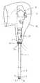
図1は内視鏡を示しており、可撓性挿入部1,2,3は、遠隔操作によって屈曲する湾曲部2が細長い挿入部可撓管1の先端に連結され、観察窓4、照明窓5及び吸引口6等が先端面に配置された先端部本体3が湾曲部2の先端に連結されて構成されている。
【0010】
挿入部可撓管1の基端が連結された操作部10には、湾曲部2を遠隔的に屈曲操作する湾曲操作ノブ11等が配置されており、湾曲操作ノブ11を回転操作することによって湾曲部2が屈曲する。
【0011】
挿入部可撓管1の基端付近を囲むように、弾力性のある材料により外径が先細りのテーパ筒状に形成された折れ止め20が取り付けられている。折れ止め20は、後述する図2に詳細に図示されているように、先側へ漸次肉厚を薄くしたテーパ筒状に形成されている。
【0012】
その結果、図1に二点鎖線で示されるように、挿入部可撓管1が曲げられても操作部10との連結部近傍付近が急激に曲がらず、その部分の座屈破損が防止される。
【0013】
挿入部可撓管1の基端付近の外周面であって折れ止め20と干渉しない位置には、挿入部可撓管1を患者の体内に挿入して内視鏡検査を行う時に操作部10を汚染から防止するために操作部10に被せられる操作部カバー30の下端付近を係合させるための附帯品係合口金7が設けられている。
【0014】
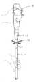
図2は、その附帯品係合口金7の周辺部分を拡大して示しており、操作部10のフレーム10aに対して、挿入部可撓管1の基端口金1cが押さえネジ環8によって押圧固定されると共に、折れ止め20と一体に形成されている折れ止め口金20aが螺合固定されている。
【0015】
附帯品係合口金7は、挿入部可撓管1の外皮1aの内側に配置されている金属製の螺旋管1bに対してロー付等により固着された筒状体であり、附帯品係合口金7部分では外皮1aが除かれて、外皮1aの端部が附帯品係合口金7に水密に固着されている。
【0016】
附帯品係合口金7の外周面(即ち、挿入部可撓管1の外周周り)にはV字状の断面形状の円周溝状の附帯品係合座7aが形成されており、弾力性のあるゴム材等からなるOリング31が、操作部カバー30の外側から附帯品係合座7aに係止される。
【0017】
このようにすることにより、挿入部可撓管1が人体内に挿入される際に操作部10が汚染から防止されると共に、折れ止め20部分が外部から隔離されて挿入部可撓管1の外周面との間に汚液等が入り込まない。そして、Oリング31を弾力的に引き伸ばして取り外せば、附帯品係合口金7から操作部カバー30の下端部を外すことができる。
【0018】
なお、図示は省略するが、操作部カバー30に代えて折れ止め20部分だけを覆う折れ止めカバーを形成し、その折れ止めカバーを附帯品係合座7aに係止しても、折れ止め20の内面と挿入部可撓管1の外周面との間への汚液の浸入は防止することができる。
【0019】
図3は、上記実施例の別の使用状態を示しており、挿入部可撓管1を水密に被覆する挿入部カバー40の基端に設けられた係合口金41の内面突起を附帯品係合座7aに係脱自在に係合させたものである。このようにすることにより、挿入部可撓管1を患者の体内に挿入する際に挿入部可撓管1が汚染されず、挿入部カバー40は、挿入部可撓管1に対して容易に着脱して交換することができる。
【0020】
図4は、挿入部可撓管1が患者の歯で噛まれないように患者に銜えさせて挿入部可撓管1を挿通案内するいわゆるマウスピース50(挿入部案内部材)を附帯品係合座7′に係脱できるようにした実施例を示している。
【0021】
この実施例の附帯品係合座7′は、例えば弾力性のあるゴム材等によって挿入部可撓管1の外周周りに突出形成された環状突起であり、マウスピース50は附帯品係合座7′を内側に通して弾性変形させることによりそこに係止され、少し力を入れてマウスピース50を引き下げれば、マウスピース50が附帯品係合座7′から外れる。
【0022】
挿入部可撓管1を患者の口に差し込む際に、このようにしてマウスピース50を附帯品係合座7′に一時的に係合させることにより、マウスピース50を安定した状態に保持してマウスピース50が意に反して落下しないようにすることができる。
【0023】
なお、挿入部可撓管1を患者の肛門から挿入する場合には、挿入部案内部材として用いられる可撓性パイプ状のいわゆるスライディングチューブを附帯品係合座7′に係合させてもよい。
【0024】
【発明の効果】
本発明によれば、挿入部可撓管の基端付近の外表面の折れ止めと干渉しない位置に、挿入部可撓管を人体内に挿入する際に用いられる附帯品を係脱自在に係合させるための附帯品係合座を設けたことにより、内視鏡検査時に内視鏡と共に用いられる附帯品を安定した状態にそこに係合させて、折れ止めの内面の汚染や患者への打撲等が起きないように内視鏡検査の安全性を向上させることができる。
【図面の簡単な説明】
【図1】本発明の第1の実施例の内視鏡を一部透視状態で示す側面図である。
【図2】本発明の第1の実施例の内視鏡の附帯品係合座付近の側面拡大断面図である。
【図3】本発明の第1の実施例の内視鏡の第2の使用例を一部断面で示す側面図である。
【図4】本発明の第2の実施例の内視鏡を一部断面で示す側面図である。
【符号の説明】
1 挿入部可撓管
7 附帯品係合口金
7a,7′ 附帯品係合座
10 操作部
20 折れ止め
30 操作部カバー(附帯品)
31 Oリング
40 挿入部カバー(附帯品)
41 係合口金
50 マウスピース(附帯品)[0001]
BACKGROUND OF THE INVENTION
The present invention relates to an endoscope.
[0002]
[Prior art]
Endoscopes are generally made of a material that is elastic to surround the portion so that the proximal end of the insertion tube flexible tube connected to the operation portion is not bent suddenly and buckled and damaged. Anti-folding is arranged.
[0003]
[Problems to be solved by the invention]
Since it is difficult to clean the spilled liquid when it enters between the inner peripheral surface of the anti-bending as described above and the outer peripheral surface of the insertion portion flexible tube, the part is completely isolated from the external sewage. Therefore, it is preferable to cover with a cover which is an accessory.
[0004]
In addition, a so-called mouthpiece (insertion guide member), which is an accessory that guides the insertion tube so that the insertion tube is not bitten by the patient's teeth, is inserted into the insertion tube. When the flexible tube is inserted into the patient's mouth, it is often held on the proximal end side of the insertion portion flexible tube with the folding stopper being elastically inserted. Because it is stable, the mouthpiece may fall from the anti-breaking part and bruise the patient's face.
[0005]
Therefore, an object of the present invention is to provide an endoscope that can improve the safety of endoscopic examination by engaging an accessory used together with the endoscope during endoscopic examination.
[0006]
[Means for Solving the Problems]
In order to achieve the above object, the endoscope according to the present invention is provided with an anti-bending material made of a resilient material in a state surrounding the vicinity of the proximal end of the insertion portion flexible tube whose proximal end is connected to the operation portion. In the endoscope, the accessory used to insert the insertion tube flexible tube into the human body at a position on the outer surface near the proximal end of the insertion tube flexible tube that does not interfere with the bend prevention is engaged / disengaged. An accessory engagement seat for freely engaging is provided.
[0007]
The accessory engagement seat may be a circumferential groove formed around the outer periphery of the insertion portion flexible tube, or may be formed to protrude around the outer periphery of the insertion portion flexible tube by an elastic material. An annular protrusion may be used.
[0008]
Further, the vicinity of the end of the operation portion cover that covers the operation portion may be engaged with the accessory engagement seat, or a bend prevention cover that covers the bend stop may be engaged. Alternatively, the vicinity of the end of the insertion portion cover that covers the insertion portion flexible tube may be engaged with the accessory engagement seat, and the insertion portion guide member through which the insertion portion flexible tube is inserted and guided is engaged. May be.
[0009]
DETAILED DESCRIPTION OF THE INVENTION
Embodiments of the present invention will be described with reference to the drawings.
FIG. 1 shows an endoscope. The
[0010]
A
[0011]
A
[0012]
As a result, as shown by a two-dot chain line in FIG. 1, even if the insertion portion
[0013]
At the position on the outer peripheral surface near the base end of the insertion portion
[0014]
FIG. 2 is an enlarged view of the peripheral portion of the
[0015]
The accessory
[0016]
An
[0017]
In this way, when the insertion portion
[0018]
Although illustration is omitted, it is possible to form the anti-folding cover that covers only the
[0019]
FIG. 3 shows another state of use of the above-described embodiment, in which the protrusion on the inner surface of the engaging base 41 provided at the proximal end of the
[0020]
FIG. 4 shows an accessory engagement with a so-called mouthpiece 50 (insertion portion guide member) that inserts and guides the insertion portion
[0021]
The
[0022]
When the insertion portion
[0023]
When the insertion portion
[0024]
【The invention's effect】
According to the present invention, the accessory used when inserting the insertion portion flexible tube into the human body is detachably engaged at a position where it does not interfere with the bend of the outer surface near the proximal end of the insertion portion flexible tube. By providing an accessory engaging seat for matching, the accessory used together with the endoscope during endoscopy can be engaged in a stable state to prevent contamination of the inner surface of the anti-folding or patient The safety of endoscopy can be improved so that bruises do not occur.
[Brief description of the drawings]
FIG. 1 is a side view showing an endoscope according to a first embodiment of the present invention in a partially transparent state.
FIG. 2 is an enlarged side sectional view of the vicinity of an accessory engagement seat of the endoscope according to the first embodiment of the present invention.
FIG. 3 is a side view showing a second example of use of the endoscope of the first embodiment of the present invention in a partial cross section.
FIG. 4 is a side view showing a partial cross section of an endoscope according to a second embodiment of the present invention.
[Explanation of symbols]
DESCRIPTION OF
31 O-
41
Claims (7)
Translated fromJapanese上記挿入部可撓管の基端付近の外表面であって上記折れ止めと干渉しない位置に、上記挿入部可撓管を人体内に挿入する際に用いられる附帯品を係脱自在に係合させるための附帯品係合座を備え、
上記附帯品係合座が、上記挿入部可撓管の外皮の内側に配置されている金属製の螺旋管に固着された筒状体の外周面に形成されて、上記挿入部可撓管の外皮が上記附帯品係合座部分では取り除かれていることを特徴とする内視鏡。In an endoscope in which a bending stopper made of a resilient material is arranged in a state surrounding the vicinity of the proximal end of the insertion tube flexible tube whose proximal end is connected to the operation unit,
Removably engage the accessory used to insert the insertion tube flexible tube into the human body at a position on the outer surface near the proximal end of the insertion tube flexible tube that does not interfere with the bend prevention. With an accessory engagement seatfor
The accessory engagement seat is formed on an outer peripheral surface of a cylindrical body fixed to a metal spiral tube disposed inside the outer skin of the insertion portion flexible tube, and An endoscope characterized in that anouter skin is removed from the accessory engaging seat portion .
Priority Applications (1)
| Application Number | Priority Date | Filing Date | Title |
|---|---|---|---|
| JP2002164215AJP4087156B2 (en) | 2002-06-05 | 2002-06-05 | Endoscope |
Applications Claiming Priority (1)
| Application Number | Priority Date | Filing Date | Title |
|---|---|---|---|
| JP2002164215AJP4087156B2 (en) | 2002-06-05 | 2002-06-05 | Endoscope |
Publications (2)
| Publication Number | Publication Date |
|---|---|
| JP2004008384A JP2004008384A (en) | 2004-01-15 |
| JP4087156B2true JP4087156B2 (en) | 2008-05-21 |
Family
ID=30432422
Family Applications (1)
| Application Number | Title | Priority Date | Filing Date |
|---|---|---|---|
| JP2002164215AExpired - Fee RelatedJP4087156B2 (en) | 2002-06-05 | 2002-06-05 | Endoscope |
Country Status (1)
| Country | Link |
|---|---|
| JP (1) | JP4087156B2 (en) |
Cited By (2)
| Publication number | Priority date | Publication date | Assignee | Title |
|---|---|---|---|---|
| US8764853B2 (en) | 2007-07-11 | 2014-07-01 | Basf Corporation | Non-aqueous electrolytic solutions and electrochemical cells comprising the same |
| US9246187B2 (en) | 2013-03-14 | 2016-01-26 | Uchicago Argonne, Llc | Non-aqueous electrolyte for lithium-ion battery |
Families Citing this family (1)
| Publication number | Priority date | Publication date | Assignee | Title |
|---|---|---|---|---|
| CN118384037B (en)* | 2024-06-24 | 2024-09-13 | 暨南大学附属第一医院(广州华侨医院) | Nursing nasal feeding tube auxiliary feeding tube device |
- 2002
- 2002-06-05JPJP2002164215Apatent/JP4087156B2/ennot_activeExpired - Fee Related
Cited By (2)
| Publication number | Priority date | Publication date | Assignee | Title |
|---|---|---|---|---|
| US8764853B2 (en) | 2007-07-11 | 2014-07-01 | Basf Corporation | Non-aqueous electrolytic solutions and electrochemical cells comprising the same |
| US9246187B2 (en) | 2013-03-14 | 2016-01-26 | Uchicago Argonne, Llc | Non-aqueous electrolyte for lithium-ion battery |
Also Published As
| Publication number | Publication date |
|---|---|
| JP2004008384A (en) | 2004-01-15 |
Similar Documents
| Publication | Publication Date | Title |
|---|---|---|
| CN100558285C (en) | Endoscope insertion portion, endoscope, and endoscope system | |
| AU752555B2 (en) | Video rectoscope | |
| US6095811A (en) | Gripping handle for diagnostic instrument | |
| EP3329833B1 (en) | Duodenoscope protected with disposable consumables | |
| US20150094611A1 (en) | Method and Device for Improved Hygiene During using Endoscopic accessory tools | |
| JP4087156B2 (en) | Endoscope | |
| JP2000342516A (en) | Treatment endoscope and treatment tool | |
| US20220211261A1 (en) | Endoscopy and hydrotherapy speculum | |
| JP4199560B2 (en) | Endoscope with sheath | |
| JP3756589B2 (en) | Endoscope | |
| JP3276197B2 (en) | Endoscope | |
| JP4135884B2 (en) | Endoscope with sheath | |
| JP3989773B2 (en) | Endoscope with sheath | |
| JP2002301010A (en) | Hooded endoscope tip | |
| JP5686711B2 (en) | Endoscope plug body and endoscope having the same | |
| JP2005230084A (en) | Balloon attaching tool | |
| JP5901497B2 (en) | Endoscope adapter | |
| CN219699881U (en) | Endoscope protector and endoscope | |
| JP4542351B2 (en) | Endoscope | |
| JP3931273B2 (en) | Endoscope cover | |
| JP4027720B2 (en) | Endoscope with sheath | |
| JPS6282934A (en) | Anoscope adaptor | |
| JP4634634B2 (en) | End of the hooded endoscope | |
| JP2010017449A (en) | Uterus endoscope | |
| JP3999043B2 (en) | Endoscope with sheath |
Legal Events
| Date | Code | Title | Description |
|---|---|---|---|
| A621 | Written request for application examination | Free format text:JAPANESE INTERMEDIATE CODE: A621 Effective date:20050407 | |
| A977 | Report on retrieval | Free format text:JAPANESE INTERMEDIATE CODE: A971007 Effective date:20071101 | |
| A131 | Notification of reasons for refusal | Free format text:JAPANESE INTERMEDIATE CODE: A131 Effective date:20071115 | |
| A521 | Written amendment | Free format text:JAPANESE INTERMEDIATE CODE: A523 Effective date:20080108 | |
| TRDD | Decision of grant or rejection written | ||
| A01 | Written decision to grant a patent or to grant a registration (utility model) | Free format text:JAPANESE INTERMEDIATE CODE: A01 Effective date:20080214 | |
| A61 | First payment of annual fees (during grant procedure) | Free format text:JAPANESE INTERMEDIATE CODE: A61 Effective date:20080220 | |
| FPAY | Renewal fee payment (event date is renewal date of database) | Free format text:PAYMENT UNTIL: 20110228 Year of fee payment:3 | |
| R150 | Certificate of patent or registration of utility model | Free format text:JAPANESE INTERMEDIATE CODE: R150 | |
| LAPS | Cancellation because of no payment of annual fees |