JP4086621B2 - Surgical instrument handle structure - Google Patents
Surgical instrument handle structureDownload PDFInfo
- Publication number
- JP4086621B2 JP4086621B2JP2002313415AJP2002313415AJP4086621B2JP 4086621 B2JP4086621 B2JP 4086621B2JP 2002313415 AJP2002313415 AJP 2002313415AJP 2002313415 AJP2002313415 AJP 2002313415AJP 4086621 B2JP4086621 B2JP 4086621B2
- Authority
- JP
- Japan
- Prior art keywords
- lock
- state
- surgical instrument
- unit
- operated
- Prior art date
- Legal status (The legal status is an assumption and is not a legal conclusion. Google has not performed a legal analysis and makes no representation as to the accuracy of the status listed.)
- Expired - Fee Related
Links
- 230000005540biological transmissionEffects0.000claimsdescription19
- 230000007704transitionEffects0.000claimsdescription6
- 238000010276constructionMethods0.000claims1
- 238000000034methodMethods0.000description13
- 210000000078clawAnatomy0.000description9
- 230000001105regulatory effectEffects0.000description9
- 238000012790confirmationMethods0.000description3
- 230000007257malfunctionEffects0.000description3
- NJPPVKZQTLUDBO-UHFFFAOYSA-NnovaluronChemical compoundC1=C(Cl)C(OC(F)(F)C(OC(F)(F)F)F)=CC=C1NC(=O)NC(=O)C1=C(F)C=CC=C1FNJPPVKZQTLUDBO-UHFFFAOYSA-N0.000description3
- 230000006835compressionEffects0.000description2
- 238000007906compressionMethods0.000description2
- 239000012636effectorSubstances0.000description2
- 238000013459approachMethods0.000description1
- 238000005452bendingMethods0.000description1
- 238000010586diagramMethods0.000description1
- 230000000694effectsEffects0.000description1
- 238000005516engineering processMethods0.000description1
- 230000000149penetrating effectEffects0.000description1
- 238000009958sewingMethods0.000description1
Images


Landscapes
- Surgical Instruments (AREA)
Description
Translated fromJapanese【0001】
【発明の属する技術分野】
本発明は、外科手術に用いられる、人体の生体組織の縫合を行う自動縫合器等の外科用器具のハンドル構造に関する。
【0002】
【従来の技術】
近年の医療技術の発展に伴って、外科用器具自体もまた非常に複雑化してきている。これら外科用器具の複雑化が進行するのと同時に、操作方法も多種多様な複雑化したものがあり、例えば、その自動縫合器もその1つに該当する。このような自動縫合器では、最終目的である縫合を行うために、大別して、組織の適切な位置決め・把持(クランプとも言う)を行う第1の作動と、組織の切除及び縫合(ファイヤとも言う)を行う第2の作動の2つの作動が存在する。
【0003】
このような2つの作動に対応するために、第1トリガと、第2トリガとを備えるハンドルが知られている(例えば、特許文献1。)。この特許文献1のハンドル構造では、第1トリガが、ハンドグリップから間隔の空いた未作動の第1トリガ位置から、ハンドグリップに隣接する完全に作動した第1トリガ位置へと反時計回りに旋回可能になっており、第2トリガが、第1トリガ位置から間隔の空いた未作動の第2トリガ位置から、第1トリガに隣接する完全に作動した第2トリガ位置へと反時計回りに旋回可能となっており、第1トリガが、第2トリガとハンドグリップとの間に位置している。
【0004】
そして、ハンドルよりも先端部にあるエンドエフェクターと第1トリガとは、第1伝導アッセンブリーによってつながれ、エンドエフェクターと第2トリガとは、第2伝導アッセンブリーによってつながれている。第1トリガを引くことにより、第1伝動アッセンブリーが基端方向へと移動して、第1の作動である組織の適切な位置決めが行われる。また、第2トリガを引くことにより、第2伝導アッセンブリーが先端方向へと移動して、第2の作動である組織の切除及び縫合が行われる。
【0005】
ところで、この作動の手順は絶対的なものであり、第1の作動の完了する前、または、第1の作動より前に第2の作動が行われることがないように、そのような誤作動を防ぐための手段が必要となる。このため、特許文献1において、第1トリガが未作動第1トリガに位置するとき、第2トリガは第2伝導アッセンブリーによって反時計回りの旋回が阻止されている。その一方で、第1トリガが未作動第1トリガ位置からハンドグリップに向かって旋回するときに、第2伝導アッセンブリーは、第2トリガの旋回ができるように先端方向へと移動する。こうして、第1トリガを引くまでは、第2トリガを引くことができないが、第1トリガを引いて初めて、第2トリガを引くことができるようになっている。
【0006】
第1の作動である組織の位置決めを適切に行うことは非常に重要であり、間違った部位で、第2の作動である組織の切除及び縫合をすることがないように、また、不完全な縫合による組織のダメージが発生することがないように、慎重に正確な位置で組織の把持を行う必要がある。そのため、この第1の作動は、しばしば、やり直しを必要とし、そのために、第1トリガは、作動中に、未作動第1トリガ位置へと戻ることができるようになっていなければならない。
【0007】
その一方で、第1の作動が適正に完了した後、第2の作動が開始されたならば、組織の把持解除といった誤作動が行われないようにしなければならない。
【0008】
【特許文献1】
特開平10−197号公報(特許請求の範囲、図1、図5〜図10)
【0009】
【発明が解決しようとする課題】
上記従来の構成では、第1トリガが引かれた後でも解除ボタンを操作することができるので、組織の把持のやり直しをすることはできるが、同時に第2トリガが操作可能となっているために、組織の位置決め、即ち第1の作動が適切ではないにもかかわらず、操作可能となっている第2トリガを操作するという誤操作を招くおそれがある。
【0010】
さらには、第2トリガの操作中においても、解除ボタンを操作することができるので、第2の作動を実行中にもかかわらず、第1の作動が解除されるという誤作動・誤操作を招くおそれがある。
【0011】
このように、従来の構成では、誤操作を防ぐための手段が不十分であるという問題がある。
【0012】
本発明は、かかる課題に鑑みなされたもので、その目的は、誤操作の可能性が低減され、且つ、操作手順に一貫性がある外科用器具のハンドル構造を提供することである。また、本発明の他の目的は、一貫性を有しつつ、操作のやり直しが容易にできるという柔軟性を有する外科用器具のハンドル構造を提供することである。
【0013】
【課題を解決するための手段】
前述した目的を達成するために、本発明は、第1の作動と第2の作動とを行う先端作動部を有する外科用器具の操作を行うための外科用器具のハンドル構造であって、
先端作動部を開始状態から第2の作動開始可能状態へと遷移させる第1の作動を行うために操作される第1の操作部と、
第2の作動を行うために操作される第2の操作部と、
第2の操作部を操作不可にする第1のロック部と、
前記第1のロック部をロック作動状態からロック解除状態へと遷移させるために操作される第3の操作部と、
第3の操作部を操作不可にする第2のロック部と、
を備え、第2のロック部は、第1の操作部によって前記先端作動部が第2の作動開始可能状態となった時にのみロック解除状態となることを特徴とする。
【0014】
本発明では、第1の操作部の操作を行って、先端作動部を開始状態から第2の作動開始可能状態へと遷移された後に直ぐには、第2の操作部が操作可能な状態にはならない。そのために、第1の作動が終了したときに、その第1の作動が適切であるかどうかを十分に確認することができ、第1の作動が不適切であるにもかかわらず、第2の作動を開始するという誤操作を防止することができる。先端作動部が第2の作動開始可能状態へと遷移した後、第3の操作部を操作することにより、第2の操作部の操作を行うことができる。この第3の操作部による操作を必要とすることにより、第2の作動開始可能状態における確認作業を行うことができるのである。一方、この第3の操作部は、先端作動部が第2の作動開始可能状態となった時にのみ操作可能となるので、第3の操作部を第2の作動開始可能状態以外の状態で操作して第2の操作部を操作可能状態にするという、誤操作も防止することができる。こうして、操作手順に一貫性を持たせることができる。
【0015】
請求項2記載の発明は、請求項1記載のものにおいて、前記先端作動部を前記第2の作動開始可能状態に保持するために、第1の操作部を操作不可とする第3のロック部と、
該第3のロック部をロック作動状態からロック解除状態へと遷移させるために操作される第4の操作部と、
をさらに備える。
【0016】
第1の操作部により先端作動部が第2の作動開始可能状態になった時において、その状態を第3のロック部により確実に保持する一方で、第1の作動のやり直しが必要とされる場合には、第4の操作部を操作することにより、そのやり直しを容易に行うことができ、操作手順に柔軟性を持たせることができる。第4の操作部を操作しても、第3の操作部が操作されない限り、第2の作動を行うことはできないので、誤操作を防止することができる。
【0017】
請求項3記載の発明は、請求項2記載のものにおいて、前記第4の操作部を操作不可にする第4のロック部をさらに備え、
前記第3の操作部は、前記第1のロック部をロック解除状態にすると同時に、第4のロック部をロック作動状態にすることを特徴とする。
【0018】
第3の操作部が操作された状態においては、第2の作動開始可能状態における確認作業が行われて、第2の操作部が操作可能となっている。この状態では、第1の作動のやり直しを行うべきではない。本発明では、第2の操作部が操作可能となっている状態においては、第4の操作部の操作は不可となっているため、第2の作動中に第1の作動の解除を行うような誤操作は確実に防止される。
【0019】
請求項4記載の発明は、請求項3記載のものにおいて、第1のロック部をロック解除状態からロック作動状態へと遷移させるために操作される第5の操作部をさらに備え、
該第5の操作部は、前記第1のロック部をロック作動状態にすると同時に、第4のロック部をロック解除状態にすることを特徴とする。
【0020】
第2の作動が終了した場合、または、第2の作動を開始する直前にその作動を中止する必要が出た場合には、第5の操作部を操作することにより、第1のロック部がロック作動状態になり、第2の操作部の操作は不可となる。また、第4のロック部がロック解除状態となり、第4の操作部の操作が可能となる。第4の操作部を操作することにより、第1の操作部が操作可能状態となる。こうして、前の状態への復帰または操作のやり直しをすることができ、操作手順に柔軟性を持たせることができる。
【0021】
請求項5記載の発明は、前記第2のロック部が、第1の操作部に設けられた規制ピンであり、該規制ピンが第1の操作部の操作と共に、前記第3の操作部の移動を阻止する位置と、移動を許容する位置とに移動することを特徴とする。
【0022】
請求項6記載の発明は、第1の操作部の操作力を前記先端作動部に伝達する第1の伝達部を備え、
前記第3のロック部は、該第1の伝達部に設けられたストッパ段部と、該ストッパ段部に係止可能となり、該第1の伝達部の方へと付勢されるロックのストッパ端部とから構成され、第1の操作部が操作されて第1の伝達部が移動すると、ロックのストッパ端部がストッパ段部に係止されて第1の伝達部の移動をロックするものであり、
前記第4の操作部の操作力により、前記ロックのストッパ端部のストッパ段部からの係止が外れることを特徴とする。
【0023】
請求項7記載の発明は、第4の操作部が回動軸を有し、回動軸を中心として回転操作可能であり、第4のロック部は、前記回動軸が挿通する溝を有するプレートからなり、該プレートの溝は、第3の操作部に一体的に連結されて第4の操作部の回動軸の回動を許容する部位と、回動軸の回動を阻止する部位とを有することを特徴とする。
【0024】
請求項8記載の発明は、第2の操作部の操作力を前記先端作動部に伝達する第2の伝達部を備え、前記第5の操作部は第2の伝達部と一体的に連結されることを特徴とする。
【0025】
【発明の実施の形態】
以下、図面を用いて本発明の実施の形態を説明する。以下の実施形態は本発明を限定するものではない。尚、説明において、術者側を近位側、術者から遠ざかる側を遠位側ということにする。
【0026】
図1は、本発明の実施の形態に係るハンドル構造を含む外科用器具全体の斜視図である。この外科用器具は、自動縫合器であり、既存のものの主構成と同様に、主として、器具の遠位側に位置する先端作動部10と、器具の近位側に位置するハンドル部30と、先端作動部10とハンドル部30とを連結するシャフト部20と、から構成される。
【0027】
ハンドル部30には、後述のように、先端作動部10に組織を把持するためのクランプトリガ(第1のトリガ、第1の操作部)32と、該クランプトリガ32よりも遠位側にあって、先端作動部10に切断・縫合を行わせるためのファイヤトリガ(第2のトリガ、第2の操作部)34とが設けられる。
【0028】
先端作動部10には、体内組織を挟持する開閉自在のジョー部12が設けられる。このジョー部12は、ステープルカートリッジ14と、このステープルカートリッジ14に対して開閉可能に連結されるアンビル16とから構成される。
【0029】
また、ステープルカートリッジ14には、U字型のステープルが両端部をアンビル16に向かって放出可能な状態で多数格納される。多数のステープルがカートリッジ14の長手方向に整列したものからなる列が、複数列、長手方向に直交する方向に並設されている。ステープルをアンビル16に向けて押出すために、テーパー面を有するテーパー部材(図示せず)がステープルの下方に、且つカートリッジ14の長手方向に摺動可能に設けられている。このテーパー部材と共に移動可能なカッターが、ステープルの中央の2列の間を、移動可能に設けられている。シャフト部20の後述の駆動ロッド24によって、このテーパー部材が摺動することで、ステープルをアンビル16の方向へ押し出すと共にカッターが移動することができるようになっている。以上の切断・縫合の動作については、公知であるため、これ以上の説明を省略する。
【0030】
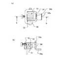
シャフト部20は、図3に示すように、外側のアウタシャフト21と、該アウタシャフト21内に同心的に配設されて、前記アンビル16に接続されたスリーブ(第1の伝達部)22と、スリーブ22内を同心的に貫通し、前記駆動手段に接続された駆動ロッド(第2の伝達部)24とから構成される。スリーブ22の近位側への移動により、アンビル16がステープルカートリッジ14に対して閉じ、遠位側への移動により、アンビル16がステープルカートリッジ14に対して開くようになっている。また、駆動ロッド24を遠位方向へと移動させることにより、駆動手段を遠位方向に駆動させて、切断・縫合ができるようになっている。シャフト部20の近位端には、回転ダイヤル26がアウタシャフト21、スリーブ22及び駆動ロッド24と共に回転可能となっており、この回転ダイヤル26を回転させることにより、先端作動部10をシャフト部20の軸線を中心として回転させて所望の回転位置に変えることができるようになっている。
【0031】
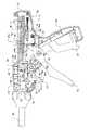
図1に示すハンドル部30は、ハンドル本体31と、ハンドル本体31に対して揺動可能となった前記クランプトリガ32、ファイヤトリガ34及び解除レバー36を有している。ハンドル本体31の下方からは、ハンドル本体31に固定のグリップ部38が延設されている。グリップ部38に対して近位側から順に、クランプトリガ32、ファイヤトリガ34及び解除レバー36が設けられる。
【0032】
クランプトリガ32は、ジョー部12のアンビル16を閉作動させるためのものであり、ファイヤトリガ34は、ステープルを打ち出し、またカッター動作を駆動するためのものであり、解除レバー36は、アンビル16を開作動させるためのものである。
【0033】
以下、ハンドル部30の詳細構造について説明する。図2に示すように、クランプトリガ32は、ピン40を介してハンドル本体31に軸着されて、ハンドル本体31に対して回動可能となっており、グリップ部38のすぐ遠位側に位置している。図4に示すように、クランプトリガ32の上端部にはギア部32aが設けられており、このギア部32aは、ハンドル本体31内で回動可能に軸着された歯車42に常時、噛合っている。また、クランプトリガ32には、そのギア部32aの近傍に、横方向に伸びる規制ピン32bが設けられる(図4(b)参照)。
【0034】
ファイヤトリガ34もピン40によりハンドル本体31に軸着されて、ハンドル本体31に対して回動可能に配設される。ファイヤトリガ34の上端部には、ファイヤトリガ34の本体に対して回転自在となりスプリング34bによって本体に対して所定の回転方向に付勢されたラッチ部34aが設けられる。ラッチ部34aは、ハンドル本体31内上方で遠近方向に移動可能に配設され前記駆動ロッド24に連結されるラックバー44のラック44aに噛合い可能となっている。ファイヤトリガ34は、ピン40においてクランプトリガ32と交差しており、ハンドル本体31外においては、ファイヤトリガ34は、クランプトリガ32よりも遠位側に、ハンドル本体31内においては、ファイヤトリガ34は、クランプトリガ32よりも近位側に配置される。ファイヤトリガ34の上部には、引張スプリング46の一端が取り付けられており、ファイヤトリガ34を常時図示の時計回りに回転する方向に押圧しており、図2の状態では、ハンドル本体31内にあるストッパーによってその時計回りの回転位置が規制されている。また、このストッパーによって規制されている状態においては、ラッチ部34aの回転も規制されている。ファイヤトリガ34の下部がグリップ部38方向に接近しても、スプリング46により、図2の位置に戻るよう付勢される。
【0035】
アンビル16の開操作を行うための解除レバー36は、図2及び図5に示すように、解除レバー36の本体から横方向に突出している円柱部36cが、ハンドル本体31に軸承され、ハンドル本体31に対して回動自在に設けられている。円柱部36cは、解除レバー36の本体から突出した長円形の台座36dからさらに横方向に突出している。解除レバー36には、図5及び図7に示すように、その上部の遠位側部において、凹空間36aと、該凹空間36a内を横断して伸びる規制棒36bとが形成される。
【0036】
ハンドル本体31内において、解除レバー36よりも遠位側には、ロックホルダ50が固着される。ロックホルダ50は、図5及び図6に示すように、その平面視でコ字状をなした枠体部を有しており、そのコ字状の両端壁に渡りピン51が架設されている。そして、そのピン51の回りには、ロックスプリング52が巻回される。さらに、ピン51には、ロックホルダ50と同様に、その平面視でコ字状をなした枠体部を有するアンビルロック54のコ字状の両端壁が、回動可能に取り付けられている。ロックスプリング52の一端は、ロックホルダ50の下方から斜めに伸びて、ハンドル本体31に形成された係止部31a(図2参照)に係止される。また、ロックスプリング52の他端は、アンビルロック54のコ字状の中央部の壁を貫通して、後方の解除レバー36の方へと伸びている。ロックスプリング52の一端がハンドル本体31の係止部31aに係止された状態で、ロックスプリング52の他端は、水平よりも上方へ付勢されており、よって、アンビルロック54は上方へと付勢されている。アンビルロック54のコ字状の中央部の壁は、やや上方へと突出しており、その上端部にあるストッパ端部54bは、後述のロッドホルダ58下面に当接している(図6、図7参照)。
【0037】
アンビルロック54の中央部の壁には、近位側へと延びるロック片部54aが形成されており、ロック片部54aは、前記解除レバー36の凹空間36a内の規制棒36bの下方へと進入している。
【0038】
ロッドホルダ58は、ハンドル本体31内において、遠近方向に移動可能に配設され、前記シャフト部20内のスリーブ22の近位端に接続される。スリーブ22及びロッドホルダ58は、ロッドホルダ58内に配設された圧縮スプリング60によって、常時、遠位方向へと付勢されており、ハンドル本体31内に形成されたストッパー部31bにロッドホルダ58の前面(遠位側面)が当接して、それ以上の遠位方向への移動が禁止される。
【0039】
また、ロッドホルダ58の下面は、図7に示したように、遠位側が引込面58a、中央部が突出面58b、近位側がギア面58cとなっている。つまり、引込面58aは、突出面58bよりも上方に引込んだ面となっている。そして、引込面58aと突出面58bとの境界は、ストッパ段部58dとなっている。前記ロックスプリング52によって上方に付勢されたアンビルロック54のストッパ端部54bは、突出面58b及び引込面58aのいずれかに当接している。ギア面58cは、前記歯車42に噛合っている。つまり、クランプトリガ32をグリップ38側に回動させることで、歯車42に動力が伝わりロッドホルダ58が近位方向に移動を行うと、ロッドホルダ58の遠位側の引込面58aに、前記アンビルロック54のストッパ端部54bがはまり込み、ストッパ段部58dに係止することで、圧縮スプリング60の付勢力に抗して、ロッドホルダ58の遠位方向への移動が規制されて、ロックされる。
【0040】
アンビルロック54のストッパ端部54bがロッドホルダ58の引込面58aにはまり込むと、アンビルロック54のロック片部54aは、解除レバー36の凹空間36aに設けられた、規制棒36bに突き当たる位置に移動する(図7(b))。この状態において、解除レバー36を回動させると、規制棒36bがアンビルロック54のロック片部54aを下方へと移動させるので、そのストッパ端部54bが、ロッドホルダ58のストッパ段部58dから外れて、ロッドホルダ58が解放される。こうして、ロッドホルダ58のロックを解除することができる。
【0041】
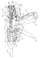
図9〜14に示すように、ハンドル部30にはファイヤトリガ34、解除レバー36の動作を規制する為の、溝を持った3つの第1カムプレート62、第2カムプレート64及び第3カムプレート66が配設されており、それぞれのカムプレート62、64、66はピン72、74によってそれぞれ連動するように規制される。以下、このカムプレートについて説明する。
【0042】
まず、第1カムプレート62は、ハンドル本体31に固定されたピン70によってハンドル本体31に対して回動可能に取り付けられる。図14に示すように、第1カムプレート62には、第1カム溝62a、第2カム溝62b、第3カム溝62c、第4溝62dが形成されている。短い円弧状の第2カム溝62bには、ハンドル本体31に固定されたピン72が挿通しており、よって、第1カムプレート62は、ピン70を中心として、ピン72が第2カム溝62bを移動することができる範囲内で、ハンドル本体31に対して揺動可能となっている。また、第1カムプレート62の上端部には、横方向へと折曲された折曲爪部62eが形成されており、通常状態において、折曲爪部62eは、後述のリターンノブ80の下部から横方向に張り出した脚部80aのすぐ前側(遠位側)に位置している。
【0043】
次に、第2カムプレート64は、第1カムプレート62とほぼ重ね合わされるようにしてハンドル本体31に配設されており、第2カムプレート64には、第1ガイド溝64a、第2ガイド溝64b、第3ガイド溝64c、カム溝64dが形成されている。第1ガイド溝64aを前記ピン72が貫通しており、これにより、第1ガイド溝64aがピン72によってガイドされて、第2カムプレート64はハンドル本体31に対して遠近方向に移動可能となっている。また、第2カムプレート64の上部には、横方向へと折曲された折曲爪部64eが形成されており、通常状態において、折曲爪部64eは、後述のリターンノブ80の下部から横方向に張り出した脚部80aのすぐ後側(近位側)に位置している。第2カムプレート64の近位端には、ハンドル本体31の近位端部に配設されたトーションスプリング84が当接しており、このトーションスプリング84によって第2カムプレート64は常時遠位側へと移動する方向に付勢されている。
【0044】
次に、第3カムプレート66には、その遠位側にガイド溝66aが形成されており、このガイド溝66aを、前記解除レバー36の円柱部36c及び長円形の台座36dが挿通している。ガイド溝66aには、その中央部に溝幅が狭くなった細溝部66bが設けられている。第3カムプレート66の近位側には、ピン74が一体的に取り付けられる。ピン74は、前記第2カムプレート64の第2ガイド溝64bと第1カムプレート62の第1カム溝62aとを貫通しており、このピン74がこれらの溝64b、62aを相対移動することができる範囲内で、第3カムプレート66はハンドル本体31に対して遠近方向に移動可能となっている。このピン74及び、前記第1カムプレート62の第4溝62dと第2カムプレート64の第3ガイド溝64cとを貫通するピン76は、リリースボタン82と一体的に連結される。よって、第3カムプレート66は、リリースボタン82と一体的に運動する。
【0045】
リリースボタン82は、ハンドル本体31のハウジングの両側壁に形成された長溝から外部に張り出されており(図14に示すようにハウジングの両側壁に配設される2つの部品からなる)、前記ピン74、76と一体的に連結されて、前記第3カムプレート66と共に遠近方向に移動可能に配設される。リリースボタン82の近位端には、ハンドル本体31内部において、ハンドル本体31の近位端部に配設された引張スプリング86が取り付けられており、この引張スプリング86によってリリースボタン82及び第3カムプレート66は常時近位側へと移動する方向に付勢されている。
【0046】
また、リリースボタン82は、ハンドル本体31の内部において、弾性のあるフックプレート88を有している(図14参照)。フックプレート88の遠位端部には、横方向に突出した凸部88aが設けられており、この凸部88aは、第2カムプレート64のカム溝64d及び第1カムプレート62の第3カム溝62c内に進入しており、これらの溝64d、62c内を移動可能となっている。
【0047】
リターンノブ80は、ハンドル本体31のハウジングの上壁に形成された長溝31cから外部に突出しており、該長溝31c内を摺動可能となっている。そして、その下部は、前記ラックバー44に一体的に連結される。
【0048】
以上のように構成されるハンドル構造を備えた外科用器具について、その動作を図5〜13より説明する。
【0049】
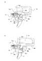
まず、術者が目的部位の組織を決めると、クランプトリガ32を握ることで、ジョー部12を閉じて、組織を把持する。この動作としては、図8に示すように、クランプトリガ32をグリップ部38側へ回動運動させることにより、クランプトリガ32の上端部に設けられたギア部32aが歯車42を介して、ロッドホルダ58の下面に設けられたギア面54cと噛合い、ロッドホルダ58を近位側に引き込む。ロッドホルダ58は、スリーブ22と連結しているため、ロッドホルダ58が引き込まれることで、スリーブ22も引き込まれ、スリーブ22の遠位端に設けられたアンビル16も近位側にシャフト部20内へと引き込まれる。すると、アンビル16に形成された斜面が、アウターシャフト21内に入り込み、アンビル16が閉位置へと移動する。
【0050】
ロッドホルダ58が引き込まれると、前述したように、ロックホルダ50のロックスプリング52に一体に連結されたアンビルロック54のストッパ端部54bが、ロッドホルダ58の下面の遠位側に設けられた引込面58aにはまり込み、ストッパ段部58dに係止することで、ロッドホルダ58の軸方向への移動が規制される。すなわち遠位側への移動が規制されるので、アンビル16は閉状態を保持する。
【0051】
クランプトリガ32がグリップ部38側へと反時計回りに回動するのに伴い、クランプトリガ32に設けられた規制ピン32bが、下方へと移動する。これによって、クランプトリガ32が回動する前は、前記第3カムプレート66が遠位側に移動することができないが、クランプトリガ32が回動した後は、第3カムプレート66が遠位側へと移動することが可能になる。
【0052】
この状態で、ジョー部12が把持した組織の位置が適正な場合には、次に進むが、把持した組織の位置が適正でない場合には、ジョー部12を開いてやり直す。やり直す場合には、解除レバー36をグリップ部38側に引き込むと、前述したように(図7(b)参照)、解除レバー36内に設けられた規制棒36bがアンビルロック54のロック片部54aを押し下げるために、そのストッパ端部54bが、ロッドホルダ58のストッパ段部58dから外れるので、ロッドホルダ58及びスリーブ22がスプリング60のバネ力により、遠位方向に戻り、アンビル16を開位置に移動させる。ロッドホルダ58が遠位方向に戻るのと同時に、クランプトリガ32も元の位置に戻る。こうして、必要があればやり直しを行い、縫合するべき組織を把持し、第1の作動を完了する。
【0053】
次に、リリースボタン82の解除を行う。これは、リリースボタン82をハンドル本体31に対して遠位方向へスライドさせることで行う。この動作により、リリースボタン82と一体的となったピン74、76及び第3カムプレート66も同距離だけ遠位側へ移動する。
【0054】
ところで、ピン74は、第1カムプレート62の第1カム溝62aを通過しており、ピン74が遠位方向に移動するときに、遠位方向に対して角度の付いた第1カム溝62aに沿って移動するために、第1カムプレート62は、ピン70を中心として、時計回りに回転し、図11に示すように下方に揺動する。第1カムプレート62が下方に移動すると、第1カムプレート62に設けられた第3カム溝62cの近位側の第1位置にあったフックプレート88の凸部88aが、第3カム溝62cのテーパー面に沿って移動して、図11に示す、第3カム溝62cの遠位側の第2位置へと移動する。フックプレート88の凸部88aが、第3カム溝62cの第2位置において、この第3カム溝62cに引っ掛かることによって、第1カムプレート62は、図11の傾斜位置を保持することができる。また、フックプレート88を有するリリースボタン82及び第3カムプレート66も遠位方向に移動した位置を保持する。
【0055】
こうして、第1カムプレート62が図11に示す傾斜位置に保持されると、第1カムプレート62の上端部に設けられた折曲爪部62eも当然下方に位置するので、リターンノブ80の脚部80aの遠位側への移動が可能となり、これにより、リターンノブ80及びラックバー44の遠位側への移動が可能になる。
【0056】
第3カムプレート66は、図11に示す遠位位置に保持されており、この状態で、ガイド溝66aを挿通する解除レバー36の円柱部36c及び台座36dは、ガイド溝66aの細溝部66bへと相対移動する。円柱部36c及び台座36dが細溝部66bに位置すると、台座36dが回動することができなくなり、結果として、解除レバー36を回転させることができなくなる。これにより、この状態において、不用意に解除レバー36の操作が行われてアンビル16が開くことを、防止している。
【0057】
次に、ファイヤトリガ34をグリップ部38側に反時計回りに回転させると、ファイヤトリガ34の上端部に設けられたラッチ部34aがラックバー44のラック44aに噛合い、そして、ラックバー44は、前述のように、すでに遠位側へ移動する準備ができているので、このファイヤトリガ34の回転とともに、ラックバー44及びこれに連結された駆動ロッド24が遠位側へと移動する(図12)。ファイヤトリガ34の一回の反時計回りへの回転だけでは、ステープルカートリッジ14内のテーパー部材がその全行程を移動できない場合には、ファイヤトリガ34をそのスプリング46のばね力により図10の状態に戻して、再度、グリップ部38側への反時計回りの回動を行い、必要な回数だけ反復回動を繰り返す。こうして、ステープルを打ち出して組織の縫合を行うと共に、組織の切断を行い、第2の作動が完了する。
【0058】
こうして、縫合及び切断が終了すると、手動によってリターンノブ80を近位側に移動させる(図13)。リターンノブ80をハンドル本体31のハウジング端面まで近位側に移動させると、リターンノブ80の横方向に突出している脚部80aが、第2カムプレート64の折曲爪部64eを、トーションスプリング84の付勢力に抗して、近位側へと押し込むので、第2カムプレート64も近位側に移動する。第2カムプレート64が近位側に移動すると、図11に示すように、第1カムプレート62の第3カム溝62cの第2位置に位置付けられていたフックプレート88の凸部88aが、第2カムプレート64のカム溝64dのテーパ面に沿って移動させられて、第3カム溝62cの第1位置へと戻る。
【0059】
フックプレート88の凸部88aが第1の位置に戻るのと同時に、引張スプリング86のバネ力により、ピン74、76すなわちリリースボタン82が近位側の図9に示す位置に戻る。するとピン74、76が第1カムプレート62に設けられた第1カム溝62a、第2カム溝62bに沿って移動するため、第1カムプレート62も元の位置に戻る。これに従って、第1カムプレート62は、ピン70を中心として反時計回りに回動して、元の位置に戻る。
【0060】
第3カムプレート66は、前述したようにリリースボタン82と一体的に移動するので、リリースボタン82と一緒に、図10に示す位置に戻る。これにより、その第3カムプレート66のガイド溝66aと、解除レバー36の円柱部36c及び台座36dとの間の係合関係が解除されて、解除レバー36を回転することが可能になる。
【0061】
最後に、アンビル16を開位置へ移動するための操作は、解除レバー36をグリップ部38側に引き込むと、前述したように、アンビルロック54のストッパ端部54bがロッドホルダ58のストッパ段部58dから外れて、ロッドホルダ58及びスリーブ22が遠位側に移動し、アンビル16を開位置に移動させる。こうして、外科用器具を組織から退避させることができる。
【0062】
以上の操作をまとめると、図15の表のようになる。表において、○はトリガ、ボタン、ノブが操作可能であることを表し、×は操作不可であることを表す。
【0063】
まず、スタート時つまり開始状態においては、クランプトリガ32(第1の操作部)と解除レバー36(第4の操作部)とが操作可能となっており、ファイヤトリガ34(第2の操作部)、リリースボタン82(第3の操作部)及びリターンノブ80(第5の操作部)は操作不可となっている。但し、解除レバー36は、フリーとなっているだけであり(図7(a)参照)、その規制棒36bがアンビルロック54のロック片部54aと係り合わないために、回動操作を行っても何の変化ももたらさない。ファイヤトリガ34及びリターンノブ80は、第1カムプレート62の折曲爪部62e(第1のロック部)によって回動及び移動がそれぞれ阻止されている。また、リリースボタン82は、クランプトリガ32の規制ピン32b(第2のロック部)によって遠位側への移動が阻止されている。
【0064】
次に、この状態からクランプトリガ32を完全に操作すると、クランプトリガ32がロックされて操作不可となり、リリースボタン82が操作可能に変化し、クランプ状態(第2作動開始可能状態)となる。クランプトリガ32のロックは、アンビルロック54のストッパ端部54bとロッドホルダ58のストッパ段部58d(これらで第3のロック部が構成される)との係合により行われる。この状態において、操作可能である解除レバー36を操作することにより、アンビルロック54のストッパ端部54bとロッドホルダ58との係合を解除し、スタート時に戻ることができる。また、リリースボタン82は、クランプトリガ32が回動してその規制ピン32bが下方へと退避することにより、遠位側への移動が許容される。
【0065】
次に、このリリースボタン82を操作すると、ファイヤトリガ34及びリターンノブ80が操作可能となり、解除レバー36及びリリースボタン82が操作不可に変化し、リリース状態となる。リリースボタン82は、そのフックプレート88の凸部88aが第1カムプレート62の第3カム溝62cの第2位置へと保持されることにより、ロックされる。また、解除レバー36は、リリースボタン82と一体に移動する第3カムプレート66のガイド溝66aの細溝部66b(第4のロック部)によって回動が阻止される。また、ファイヤトリガ34及びリターンノブ80は、第1カムプレート62の折曲爪部62eがリターンノブ80の脚部80aとの干渉位置から下方へと退避することにより、回動及び移動がそれぞれ可能となる。この状態で、ファイヤトリガ34を操作すると、ファイヤが行われる。
【0066】
ファイヤトリガ34及びリターンノブ80またはリターンノブ80のみを操作すると、ファイヤトリガ34及びリターンノブ80が操作不可となり、解除レバー36及びリリースボタン82が操作可能に変化してリターン時となる。この状態は、クランプ時と同じである。そして、この状態から解除レバー36を操作すると、スタート時に戻る。
【0067】
このように、本実施形態においては、トリガ、ボタン、ノブの操作手順が確定されて一貫性を有しており、誤った手順を術者が行うことはできないようになっている。その一方で、手順のやり直しが容易にできるという柔軟性を有している。例えば、クランプトリガ32を操作して、組織を把持した後、その位置が正しいかどうかの確認を行わないうちに、ファイヤトリガ34を操作することはできず、リリースボタン82の操作を行ってはじめてファイヤトリガ34を操作することができる。このリリースボタン82は、組織を把持していなければ操作することはできず、組織を把持前に縫合が始まることはない。また、万が一、リリースボタン82を操作した直後に、前の状態に戻りたい場合には、リターンノブ80を操作することで、クランプ時と同じ状態に戻ることができる。また、リリースボタン82の操作を行った後には、誤って、解除レバー36を操作してアンビル16を開くといったことはできない。これにより、縫合・切断中にアンビル16が開くといった事態は回避できる。その一方で、リリースボタン82を操作する前には、何時でも、解除レバー36を操作して、アンビル16を開き、先端作動部10の位置決めからやり直すことができる。
【0068】
【発明の効果】
以上説明したように本発明によれば、先端作動部が第2の作動開始可能状態へと遷移した後、第3の操作部を操作して、第1のロック部をロック解除状態へと遷移させるために操作することにより、第2の作動開始可能状態における確認作業を行うことができ、誤操作の可能性が低減できる。また、第3の操作部は、先端作動部が第2の作動開始可能状態となった時にのみ解除されるので、第3の操作部を第2の作動開始可能状態以外の状態で操作することにより、第2の操作部を操作可能状態にするという、誤操作も防止することができる。こうして、操作手順に一貫性を持たせることができる。
【図面の簡単な説明】
【図1】本発明の実施の形態に係るハンドル構造を含む外科用器具の全体斜視図である。
【図2】本発明のハンドル部の内部構造を表す側面図であり、スタート時の状態を表す。尚、第1ないし第3カムプレートを取り除いている。
【図3】シャフト部の一部の断面図と、ハンドル部の内部の一部を表す図である。
【図4】(a)はクランプトリガとファイヤトリガの組立体の側面図、(b)はその組立体の遠位端側から見た図である。
【図5】解除レバーと、アンビルロックの分解斜視図である。
【図6】(a)はロックホルダとアンビルロックの組立体の平面図、(b)は(a)の組立体のb−b線に沿って見た断面図である。
【図7】(a)、(b)はアンビルロックの動作を表す説明図であり、(a)はロック解除時、(b)はロック時を表す。
【図8】本発明のハンドル部の内部構造を表す側面図であり、クランプ時の状態を表す。尚、第1ないし第3カムプレートを取り除いている。
【図9】本発明のハンドル部の内部構造を表す側面図であり、スタート時の状態を表す。
【図10】本発明のハンドル部の内部構造を表す側面図であり、クランプ時の状態を表す。
【図11】本発明のハンドル部の内部構造を表す側面図であり、リリース時の状態を表す。
【図12】本発明のハンドル部の内部構造を表す側面図であり、ファイヤ時の状態を表す。
【図13】本発明のハンドル部の内部構造を表す側面図であり、リターン時の状態を表す。
【図14】第1ないし第3カムプレート及びリリースボタンの分解斜視図である。
【図15】本発明の各操作部と、その操作可能・不可の状態の遷移を表す表である。
【符号の説明】
10 先端作動部
22 スリーブ(第1の伝達部)
24 駆動ロッド(第2の伝達部)
30 ハンドル部
32 クランプトリガ(第1の操作部)
32b 規制ピン(第2のロック部)
34 ファイヤトリガ(第2の操作部)
36 解除レバー(第4の操作部)
54b ストッパ端部(第3のロック部)
58d ストッパ段部(第3のロック部)
62e 折曲爪部(第1のロック部)
66 カムプレート
66a ガイド溝
66b 細溝部
80 リターンノブ(第5の操作部)
82 リリースボタン(第3の操作部)[0001]
BACKGROUND OF THE INVENTION
The present invention relates to a handle structure of a surgical instrument such as an automatic suturing device for suturing a living body tissue used in a surgical operation.
[0002]
[Prior art]
With the development of medical technology in recent years, surgical instruments themselves have become very complex. At the same time as these surgical instruments are becoming more complicated, there are various complicated operation methods, for example, an automatic suturing device corresponds to one of them. In such an automatic suturing device, in order to perform the final purpose of suturing, it is roughly divided into a first operation for appropriately positioning and grasping (also referred to as a clamp) of tissue, and a tissue excision and suturing (also referred to as fire). There are two actions of the second action to do.
[0003]
In order to cope with such two operations, a handle including a first trigger and a second trigger is known (for example, Patent Document 1). In the handle structure of Patent Document 1, the first trigger pivots counterclockwise from an unactuated first trigger position spaced from the handgrip to a fully actuated first trigger position adjacent to the handgrip. Enabled and the second trigger pivots counterclockwise from an unactuated second trigger position spaced from the first trigger position to a fully activated second trigger position adjacent to the first trigger The first trigger is located between the second trigger and the hand grip.
[0004]
The end effector at the tip of the handle and the first trigger are connected by the first conduction assembly, and the end effector and the second trigger are connected by the second conduction assembly. By pulling the first trigger, the first transmission assembly moves in the proximal direction, and the tissue is properly positioned as the first operation. Further, by pulling the second trigger, the second conduction assembly moves in the distal direction, and the tissue is excised and sutured as the second operation.
[0005]
By the way, the procedure of this operation is absolute, and such a malfunction does not occur before the first operation is completed or the second operation is not performed before the first operation. Means to prevent this are necessary. For this reason, in Patent Document 1, when the first trigger is positioned at the unactuated first trigger, the second trigger is prevented from turning counterclockwise by the second conduction assembly. On the other hand, when the first trigger turns from the non-actuated first trigger position toward the handgrip, the second conduction assembly moves in the distal direction so that the second trigger can turn. Thus, the second trigger cannot be pulled until the first trigger is pulled, but the second trigger can be pulled only after the first trigger is pulled.
[0006]
Proper positioning of the tissue, which is the first operation, is very important, so that the second operation, tissue excision and suturing is not performed at the wrong site, and incomplete. It is necessary to carefully grasp the tissue at an accurate position so that the tissue is not damaged by the suturing. As such, this first actuation often requires a redo, so the first trigger must be able to return to the unactuated first trigger position during actuation.
[0007]
On the other hand, if the second operation is started after the first operation is properly completed, it is necessary to prevent a malfunction such as release of the tissue from being grasped.
[0008]
[Patent Document 1]
Japanese Patent Laid-Open No. 10-197 (Claims, FIGS. 1, 5 to 10)
[0009]
[Problems to be solved by the invention]
In the above conventional configuration, the release button can be operated even after the first trigger is pulled, so that the tissue can be re-operated, but the second trigger can be operated at the same time. In spite of the inappropriate positioning of the tissue, i.e., the first operation, there is a risk of erroneous operation of operating the second trigger that is operable.
[0010]
Furthermore, since the release button can be operated even during the operation of the second trigger, there is a possibility of causing a malfunction / operation error that the first action is released even though the second action is being performed. There is.
[0011]
As described above, the conventional configuration has a problem that means for preventing an erroneous operation are insufficient.
[0012]
The present invention has been made in view of the above problems, and an object thereof is to provide a handle structure of a surgical instrument in which the possibility of erroneous operation is reduced and the operation procedure is consistent. Another object of the present invention is to provide a handle structure for a surgical instrument that is flexible and can be easily re-operated while being consistent.
[0013]
[Means for Solving the Problems]
To achieve the foregoing object, the present invention provides a surgical instrument handle structure for operating a surgical instrument having a tip actuating portion for performing a first operation and a second operation.
A first operation unit operated to perform a first operation for causing the tip operation unit to transition from the start state to the second operation startable state;
A second operating portion operated to perform a second operation;
A first lock unit that disables the second operation unit;
A third operation unit operated to shift the first lock unit from the locked operation state to the unlocked state;
A second lock portion for disabling the third operation portion;
The second lock portion is characterized in that it is unlocked only when the tip operating portion is brought into a second operation startable state by the first operation portion.
[0014]
In the present invention, immediately after the operation of the first operating unit is performed and the tip operating unit is changed from the start state to the second operation startable state, the second operating unit is in the operable state. Don't be. Therefore, when the first operation is finished, it can be sufficiently confirmed whether the first operation is appropriate, and the second operation is performed despite the inappropriate first operation. An erroneous operation of starting the operation can be prevented. After the distal end working unit transitions to the second operation startable state, the second operating unit can be operated by operating the third operating unit. By requiring the operation by the third operation unit, the confirmation work in the second operation startable state can be performed. On the other hand, since the third operation unit can be operated only when the tip operation unit is in the second operation startable state, the third operation unit is operated in a state other than the second operation startable state. Thus, an erroneous operation of making the second operation unit operable is also prevented. In this way, the operation procedure can be made consistent.
[0015]
According to a second aspect of the present invention, there is provided the third lock portion according to the first aspect, wherein the first operation portion cannot be operated in order to hold the tip operation portion in the second operation startable state. When,
A fourth operation unit operated to shift the third lock unit from the locked operation state to the unlocked state;
Is further provided.
[0016]
When the tip operating portion is brought into the second operation start ready state by the first operation portion, the state is securely held by the third lock portion, while the first operation needs to be repeated. In this case, it is possible to easily perform the operation again by operating the fourth operation unit, and to make the operation procedure flexible. Even if the fourth operation unit is operated, the second operation cannot be performed unless the third operation unit is operated, so that an erroneous operation can be prevented.
[0017]
The invention according to claim 3 is the one according to claim 2, further comprising a fourth lock portion that disables the operation of the fourth operation portion,
The third operation unit is characterized in that the first lock unit is brought into an unlocked state and at the same time the fourth lock unit is brought into a lock operating state.
[0018]
In the state where the third operation unit is operated, the confirmation operation in the second operation startable state is performed, and the second operation unit can be operated. In this state, the first operation should not be redone. In the present invention, since the operation of the fourth operation unit is not possible in the state where the second operation unit is operable, the first operation is canceled during the second operation. An erroneous operation is surely prevented.
[0019]
The invention described in claim 4 is the one described in claim 3, further comprising a fifth operation portion operated to shift the first lock portion from the unlocked state to the locked operation state,
The fifth operation section is characterized in that the first lock section is brought into a lock operation state and at the same time the fourth lock section is brought into a lock release state.
[0020]
When the second operation is finished, or when it becomes necessary to stop the operation immediately before the second operation is started, the first lock unit is operated by operating the fifth operation unit. The lock is activated, and the operation of the second operation unit is disabled. Further, the fourth lock unit is unlocked, and the fourth operation unit can be operated. By operating the fourth operation unit, the first operation unit becomes operable. In this way, it is possible to return to the previous state or redo the operation, and to give flexibility to the operation procedure.
[0021]
According to a fifth aspect of the present invention, the second lock portion is a restriction pin provided in the first operation portion, and the restriction pin is provided along with the operation of the first operation portion. It moves to the position which prevents a movement, and the position which accept | permits a movement, It is characterized by the above-mentioned.
[0022]
The invention according to claim 6 includes a first transmission unit that transmits an operation force of the first operation unit to the tip operating unit,
The third lock portion includes a stopper step provided in the first transmission portion, and a lock stopper which can be locked to the stopper step portion and is urged toward the first transmission portion. When the first transmission portion is moved by operating the first operation portion, the stopper end portion of the lock is locked to the stopper step portion to lock the movement of the first transmission portion. And
The locking force of the stopper end of the lock is released from the stopper step by the operating force of the fourth operating part.
[0023]
According to a seventh aspect of the present invention, the fourth operation portion has a rotation shaft and can be rotated around the rotation shaft, and the fourth lock portion has a groove through which the rotation shaft is inserted. The plate comprises a plate, and the groove of the plate is integrally connected to the third operation portion and allows the rotation of the rotation shaft of the fourth operation portion, and the portion that prevents the rotation of the rotation shaft. It is characterized by having.
[0024]
The invention according to claim 8 is provided with a second transmission part that transmits the operating force of the second operation part to the tip actuating part, and the fifth operation part is integrally connected to the second transmission part. It is characterized by that.
[0025]
DETAILED DESCRIPTION OF THE INVENTION
Hereinafter, embodiments of the present invention will be described with reference to the drawings. The following embodiments do not limit the present invention. In the description, the operator side is referred to as the proximal side, and the side away from the operator is referred to as the distal side.
[0026]
FIG. 1 is a perspective view of an entire surgical instrument including a handle structure according to an embodiment of the present invention. This surgical instrument is an automatic suturing device, and, similar to the main configuration of the existing one, mainly a tip actuating part 10 located on the distal side of the instrument, a
[0027]
As will be described later, the
[0028]
The distal end working unit 10 is provided with an openable /
[0029]
Further, a large number of U-shaped staples are stored in the
[0030]
As shown in FIG. 3, the
[0031]
A
[0032]
The
[0033]
Hereinafter, the detailed structure of the
[0034]
The
[0035]
As shown in FIGS. 2 and 5, the
[0036]
In the
[0037]
A
[0038]
The
[0039]
Further, as shown in FIG. 7, the lower surface of the
[0040]
When the
[0041]
As shown in FIGS. 9 to 14, the
[0042]
First, the
[0043]
Next, the
[0044]
Next, a
[0045]
The
[0046]
Further, the
[0047]
The
[0048]
About the surgical instrument provided with the handle structure comprised as mentioned above, the operation | movement is demonstrated from FIGS.
[0049]
First, when the operator determines the tissue of the target site, the
[0050]
When the
[0051]
As the
[0052]
In this state, if the position of the tissue grasped by the
[0053]
Next, the
[0054]
Incidentally, the
[0055]
Thus, when the
[0056]
The
[0057]
Next, when the
[0058]
Thus, when the suturing and cutting are completed, the
[0059]
Simultaneously with the
[0060]
Since the
[0061]
Finally, in order to move the
[0062]
The above operations are summarized as shown in the table of FIG. In the table, ◯ indicates that the trigger, button, and knob are operable, and x indicates that the operation is not possible.
[0063]
First, at the start, that is, in the start state, the clamp trigger 32 (first operation unit) and the release lever 36 (fourth operation unit) can be operated, and the fire trigger 34 (second operation unit). The release button 82 (third operation unit) and the return knob 80 (fifth operation unit) cannot be operated. However, the
[0064]
Next, when the
[0065]
Next, when the
[0066]
When only the
[0067]
As described above, in this embodiment, the operation procedures of the trigger, the button, and the knob are fixed and consistent, and the operator cannot perform an erroneous procedure. On the other hand, it has the flexibility that the procedure can be easily redone. For example, after grasping the tissue by operating the
[0068]
【The invention's effect】
As described above, according to the present invention, after the distal end working unit transitions to the second operation startable state, the third operating unit is operated to transition the first locking unit to the unlocked state. By performing the operation, the confirmation work in the second operation startable state can be performed, and the possibility of erroneous operation can be reduced. Further, since the third operation unit is released only when the tip operation unit is in the second operation startable state, the third operation unit is operated in a state other than the second operation startable state. Accordingly, it is possible to prevent an erroneous operation of bringing the second operation unit into an operable state. In this way, the operation procedure can be made consistent.
[Brief description of the drawings]
FIG. 1 is an overall perspective view of a surgical instrument including a handle structure according to an embodiment of the present invention.
FIG. 2 is a side view showing the internal structure of the handle portion of the present invention, showing a state at the start. The first to third cam plates are removed.
FIG. 3 is a cross-sectional view of a part of the shaft part and a part of the inside of the handle part.
4A is a side view of an assembly of a clamp trigger and a fire trigger, and FIG. 4B is a view as seen from a distal end side of the assembly.
FIG. 5 is an exploded perspective view of a release lever and an anvil lock.
6A is a plan view of an assembly of a lock holder and an anvil lock, and FIG. 6B is a cross-sectional view of the assembly of FIG.
FIGS. 7A and 7B are explanatory diagrams showing the operation of an anvil lock, where FIG. 7A shows when the lock is released, and FIG.
FIG. 8 is a side view showing the internal structure of the handle portion of the present invention, and shows a state at the time of clamping. The first to third cam plates are removed.
FIG. 9 is a side view showing the internal structure of the handle portion of the present invention, showing a state at the start.
FIG. 10 is a side view showing the internal structure of the handle portion according to the present invention and showing a state at the time of clamping.
FIG. 11 is a side view showing the internal structure of the handle portion according to the present invention and showing a state at the time of release.
FIG. 12 is a side view showing the internal structure of the handle portion of the present invention, showing a state at the time of fire.
FIG. 13 is a side view showing the internal structure of the handle portion according to the present invention and showing a state at the time of return.
FIG. 14 is an exploded perspective view of first to third cam plates and a release button.
FIG. 15 is a table showing each operation unit according to the present invention and the transition of the operation enabled / disabled state.
[Explanation of symbols]
10 Tip actuator
22 Sleeve (first transmission part)
24 Drive rod (second transmission part)
30 Handle part
32 Clamp trigger (first operation part)
32b Restriction pin (second lock part)
34 Fire trigger (second operation part)
36 Release lever (fourth operating section)
54b Stopper end (third lock)
58d Stopper step (third lock)
62e Bending claw (first lock)
66 Cam plate
66a guide groove
66b narrow groove
80 Return knob (fifth operation part)
82 Release button (third control)
Claims (8)
Translated fromJapanese先端作動部を開始状態から第2の作動開始可能状態へと遷移させる第1の作動を行うために操作される第1の操作部(32)と、
第2の作動を行うために操作される第2の操作部(34)と、
第2の操作部を操作不可にする第1のロック部と、
前記第1のロック部をロック作動状態からロック解除状態へと遷移させるために操作される第3の操作部(82)と、
第3の操作部を操作不可にする第2のロック部と、
を備え、第2のロック部は、第1の操作部によって前記先端作動部が第2の作動開始可能状態となった時にのみロック解除状態となることを特徴とする外科用器具のハンドル構造。A surgical instrument handle structure for operating a surgical instrument having a tip actuating portion for performing a first action and a second action,
A first operation unit (32) operated to perform a first operation for transitioning the tip operation unit from the start state to the second operation startable state;
A second operating portion (34) operated to perform a second operation;
A first lock unit that disables the second operation unit;
A third operating portion (82) operated to transition the first locking portion from the locked operating state to the unlocked state;
A second lock portion for disabling the third operation portion;
The handle structure for a surgical instrument is characterized in that the second lock portion is unlocked only when the tip operation portion is in a second operation startable state by the first operation portion.
該第3のロック部をロック作動状態からロック解除状態へと遷移させるために操作される第4の操作部(36)と、
をさらに備えることを特徴とする請求項1記載の外科用器具のハンドル構造。A third lock portion for disabling the first operation portion to hold the tip operation portion in the second operation startable state;
A fourth operation unit (36) operated to shift the third lock unit from the locked operation state to the unlocked state;
The handle structure for a surgical instrument according to claim 1, further comprising:
前記第3の操作部は、前記第1のロック部をロック解除状態にすると同時に、第4のロック部をロック作動状態にすることを特徴とする請求項2記載の外科用器具のハンドル構造。A fourth lock unit for disabling the fourth operation unit;
3. The handle structure for a surgical instrument according to claim 2, wherein the third operation portion sets the first lock portion to an unlocked state and simultaneously sets the fourth lock portion to a lock operation state.
該第5の操作部は、前記第1のロック部をロック作動状態にすると同時に、第4のロック部をロック解除状態にすることを特徴とする請求項3記載の外科用器具のハンドル構造。A fifth operation unit (80) operated to shift the first lock unit from the unlocked state to the locked operation state;
4. The handle structure for a surgical instrument according to claim 3, wherein the fifth operation unit sets the fourth lock unit to an unlocked state simultaneously with setting the first lock unit to a lock operation state. 5.
前記第3のロック部は、該第1の伝達部に設けられたストッパ段部(58d)と、該ストッパ段部(58d)に係止可能となり、該第1の伝達部の方へと付勢されるロックのストッパ端部(54b)とから構成され、第1の操作部が操作されて第1の伝達部が移動すると、ロックのストッパ端部(54b)がストッパ段部(58d)に係止されて第1の伝達部の移動をロックするものであり、
前記第4の操作部の操作力により、前記ロックのストッパ端部のストッパ段部からの係止が外れることを特徴とする請求項2ないし5のいずれか1項に記載の外科用器具のハンドル構造。A first transmission part (22) for transmitting the operating force of the first operating part to the tip operating part;
The third lock portion can be locked to the stopper step portion (58d) provided in the first transmission portion and the stopper step portion (58d), and is attached to the first transmission portion. When the first operation portion is operated and the first transmission portion moves, the lock stopper end portion (54b) is moved to the stopper step portion (58d). Locked to lock the movement of the first transmission part,
The handle of the surgical instrument according to any one of claims 2 to 5, wherein the stopper end of the lock is released from the stopper step by the operating force of the fourth operating part. Construction.
Priority Applications (1)
| Application Number | Priority Date | Filing Date | Title |
|---|---|---|---|
| JP2002313415AJP4086621B2 (en) | 2002-10-28 | 2002-10-28 | Surgical instrument handle structure |
Applications Claiming Priority (1)
| Application Number | Priority Date | Filing Date | Title |
|---|---|---|---|
| JP2002313415AJP4086621B2 (en) | 2002-10-28 | 2002-10-28 | Surgical instrument handle structure |
Publications (2)
| Publication Number | Publication Date |
|---|---|
| JP2004147701A JP2004147701A (en) | 2004-05-27 |
| JP4086621B2true JP4086621B2 (en) | 2008-05-14 |
Family
ID=32458047
Family Applications (1)
| Application Number | Title | Priority Date | Filing Date |
|---|---|---|---|
| JP2002313415AExpired - Fee RelatedJP4086621B2 (en) | 2002-10-28 | 2002-10-28 | Surgical instrument handle structure |
Country Status (1)
| Country | Link |
|---|---|
| JP (1) | JP4086621B2 (en) |
Families Citing this family (637)
| Publication number | Priority date | Publication date | Assignee | Title |
|---|---|---|---|---|
| US11229472B2 (en) | 2001-06-12 | 2022-01-25 | Cilag Gmbh International | Modular battery powered handheld surgical instrument with multiple magnetic position sensors |
| US9060770B2 (en) | 2003-05-20 | 2015-06-23 | Ethicon Endo-Surgery, Inc. | Robotically-driven surgical instrument with E-beam driver |
| US20070084897A1 (en) | 2003-05-20 | 2007-04-19 | Shelton Frederick E Iv | Articulating surgical stapling instrument incorporating a two-piece e-beam firing mechanism |
| US8182501B2 (en) | 2004-02-27 | 2012-05-22 | Ethicon Endo-Surgery, Inc. | Ultrasonic surgical shears and method for sealing a blood vessel using same |
| US7059508B2 (en)* | 2004-06-30 | 2006-06-13 | Ethicon Endo-Surgery, Inc. | Surgical stapling instrument incorporating an uneven multistroke firing mechanism having a rotary transmission |
| US9072535B2 (en) | 2011-05-27 | 2015-07-07 | Ethicon Endo-Surgery, Inc. | Surgical stapling instruments with rotatable staple deployment arrangements |
| US7487899B2 (en)* | 2004-07-28 | 2009-02-10 | Ethicon Endo-Surgery, Inc. | Surgical instrument incorporating EAP complete firing system lockout mechanism |
| US8215531B2 (en) | 2004-07-28 | 2012-07-10 | Ethicon Endo-Surgery, Inc. | Surgical stapling instrument having a medical substance dispenser |
| US11998198B2 (en) | 2004-07-28 | 2024-06-04 | Cilag Gmbh International | Surgical stapling instrument incorporating a two-piece E-beam firing mechanism |
| US11890012B2 (en) | 2004-07-28 | 2024-02-06 | Cilag Gmbh International | Staple cartridge comprising cartridge body and attached support |
| US20060079879A1 (en) | 2004-10-08 | 2006-04-13 | Faller Craig N | Actuation mechanism for use with an ultrasonic surgical instrument |
| US7934630B2 (en) | 2005-08-31 | 2011-05-03 | Ethicon Endo-Surgery, Inc. | Staple cartridges for forming staples having differing formed staple heights |
| US7669746B2 (en) | 2005-08-31 | 2010-03-02 | Ethicon Endo-Surgery, Inc. | Staple cartridges for forming staples having differing formed staple heights |
| US11246590B2 (en) | 2005-08-31 | 2022-02-15 | Cilag Gmbh International | Staple cartridge including staple drivers having different unfired heights |
| US10159482B2 (en) | 2005-08-31 | 2018-12-25 | Ethicon Llc | Fastener cartridge assembly comprising a fixed anvil and different staple heights |
| US7673781B2 (en) | 2005-08-31 | 2010-03-09 | Ethicon Endo-Surgery, Inc. | Surgical stapling device with staple driver that supports multiple wire diameter staples |
| US11484312B2 (en) | 2005-08-31 | 2022-11-01 | Cilag Gmbh International | Staple cartridge comprising a staple driver arrangement |
| US9237891B2 (en) | 2005-08-31 | 2016-01-19 | Ethicon Endo-Surgery, Inc. | Robotically-controlled surgical stapling devices that produce formed staples having different lengths |
| US20070191713A1 (en) | 2005-10-14 | 2007-08-16 | Eichmann Stephen E | Ultrasonic device for cutting and coagulating |
| US20070106317A1 (en) | 2005-11-09 | 2007-05-10 | Shelton Frederick E Iv | Hydraulically and electrically actuated articulation joints for surgical instruments |
| US7621930B2 (en) | 2006-01-20 | 2009-11-24 | Ethicon Endo-Surgery, Inc. | Ultrasound medical instrument having a medical ultrasonic blade |
| US8186555B2 (en) | 2006-01-31 | 2012-05-29 | Ethicon Endo-Surgery, Inc. | Motor-driven surgical cutting and fastening instrument with mechanical closure system |
| US7753904B2 (en) | 2006-01-31 | 2010-07-13 | Ethicon Endo-Surgery, Inc. | Endoscopic surgical instrument with a handle that can articulate with respect to the shaft |
| US11224427B2 (en) | 2006-01-31 | 2022-01-18 | Cilag Gmbh International | Surgical stapling system including a console and retraction assembly |
| US7845537B2 (en) | 2006-01-31 | 2010-12-07 | Ethicon Endo-Surgery, Inc. | Surgical instrument having recording capabilities |
| US20120292367A1 (en) | 2006-01-31 | 2012-11-22 | Ethicon Endo-Surgery, Inc. | Robotically-controlled end effector |
| US20110295295A1 (en) | 2006-01-31 | 2011-12-01 | Ethicon Endo-Surgery, Inc. | Robotically-controlled surgical instrument having recording capabilities |
| US11793518B2 (en) | 2006-01-31 | 2023-10-24 | Cilag Gmbh International | Powered surgical instruments with firing system lockout arrangements |
| US11278279B2 (en) | 2006-01-31 | 2022-03-22 | Cilag Gmbh International | Surgical instrument assembly |
| US20110024477A1 (en) | 2009-02-06 | 2011-02-03 | Hall Steven G | Driven Surgical Stapler Improvements |
| US8820603B2 (en) | 2006-01-31 | 2014-09-02 | Ethicon Endo-Surgery, Inc. | Accessing data stored in a memory of a surgical instrument |
| US8708213B2 (en) | 2006-01-31 | 2014-04-29 | Ethicon Endo-Surgery, Inc. | Surgical instrument having a feedback system |
| US9861359B2 (en) | 2006-01-31 | 2018-01-09 | Ethicon Llc | Powered surgical instruments with firing system lockout arrangements |
| US8236010B2 (en) | 2006-03-23 | 2012-08-07 | Ethicon Endo-Surgery, Inc. | Surgical fastener and cutter with mimicking end effector |
| US8992422B2 (en) | 2006-03-23 | 2015-03-31 | Ethicon Endo-Surgery, Inc. | Robotically-controlled endoscopic accessory channel |
| US8322455B2 (en) | 2006-06-27 | 2012-12-04 | Ethicon Endo-Surgery, Inc. | Manually driven surgical cutting and fastening instrument |
| US10568652B2 (en) | 2006-09-29 | 2020-02-25 | Ethicon Llc | Surgical staples having attached drivers of different heights and stapling instruments for deploying the same |
| US7506791B2 (en) | 2006-09-29 | 2009-03-24 | Ethicon Endo-Surgery, Inc. | Surgical stapling instrument with mechanical mechanism for limiting maximum tissue compression |
| US10130359B2 (en) | 2006-09-29 | 2018-11-20 | Ethicon Llc | Method for forming a staple |
| US11980366B2 (en) | 2006-10-03 | 2024-05-14 | Cilag Gmbh International | Surgical instrument |
| US8652120B2 (en) | 2007-01-10 | 2014-02-18 | Ethicon Endo-Surgery, Inc. | Surgical instrument with wireless communication between control unit and sensor transponders |
| US8684253B2 (en) | 2007-01-10 | 2014-04-01 | Ethicon Endo-Surgery, Inc. | Surgical instrument with wireless communication between a control unit of a robotic system and remote sensor |
| US11291441B2 (en) | 2007-01-10 | 2022-04-05 | Cilag Gmbh International | Surgical instrument with wireless communication between control unit and remote sensor |
| US8632535B2 (en) | 2007-01-10 | 2014-01-21 | Ethicon Endo-Surgery, Inc. | Interlock and surgical instrument including same |
| US20080169333A1 (en) | 2007-01-11 | 2008-07-17 | Shelton Frederick E | Surgical stapler end effector with tapered distal end |
| US11039836B2 (en) | 2007-01-11 | 2021-06-22 | Cilag Gmbh International | Staple cartridge for use with a surgical stapling instrument |
| US7673782B2 (en) | 2007-03-15 | 2010-03-09 | Ethicon Endo-Surgery, Inc. | Surgical stapling instrument having a releasable buttress material |
| US8057498B2 (en) | 2007-11-30 | 2011-11-15 | Ethicon Endo-Surgery, Inc. | Ultrasonic surgical instrument blades |
| US8911460B2 (en) | 2007-03-22 | 2014-12-16 | Ethicon Endo-Surgery, Inc. | Ultrasonic surgical instruments |
| US8226675B2 (en) | 2007-03-22 | 2012-07-24 | Ethicon Endo-Surgery, Inc. | Surgical instruments |
| US8142461B2 (en) | 2007-03-22 | 2012-03-27 | Ethicon Endo-Surgery, Inc. | Surgical instruments |
| US8056787B2 (en)* | 2007-03-28 | 2011-11-15 | Ethicon Endo-Surgery, Inc. | Surgical stapling and cutting instrument with travel-indicating retraction member |
| US8893946B2 (en) | 2007-03-28 | 2014-11-25 | Ethicon Endo-Surgery, Inc. | Laparoscopic tissue thickness and clamp load measuring devices |
| US7490749B2 (en)* | 2007-03-28 | 2009-02-17 | Ethicon Endo-Surgery, Inc. | Surgical stapling and cutting instrument with manually retractable firing member |
| US11564682B2 (en) | 2007-06-04 | 2023-01-31 | Cilag Gmbh International | Surgical stapler device |
| US8931682B2 (en) | 2007-06-04 | 2015-01-13 | Ethicon Endo-Surgery, Inc. | Robotically-controlled shaft based rotary drive systems for surgical instruments |
| US7753245B2 (en) | 2007-06-22 | 2010-07-13 | Ethicon Endo-Surgery, Inc. | Surgical stapling instruments |
| US8408439B2 (en) | 2007-06-22 | 2013-04-02 | Ethicon Endo-Surgery, Inc. | Surgical stapling instrument with an articulatable end effector |
| US11849941B2 (en) | 2007-06-29 | 2023-12-26 | Cilag Gmbh International | Staple cartridge having staple cavities extending at a transverse angle relative to a longitudinal cartridge axis |
| US8523889B2 (en) | 2007-07-27 | 2013-09-03 | Ethicon Endo-Surgery, Inc. | Ultrasonic end effectors with increased active length |
| US8882791B2 (en) | 2007-07-27 | 2014-11-11 | Ethicon Endo-Surgery, Inc. | Ultrasonic surgical instruments |
| US8808319B2 (en) | 2007-07-27 | 2014-08-19 | Ethicon Endo-Surgery, Inc. | Surgical instruments |
| US9044261B2 (en) | 2007-07-31 | 2015-06-02 | Ethicon Endo-Surgery, Inc. | Temperature controlled ultrasonic surgical instruments |
| US8512365B2 (en) | 2007-07-31 | 2013-08-20 | Ethicon Endo-Surgery, Inc. | Surgical instruments |
| US8430898B2 (en) | 2007-07-31 | 2013-04-30 | Ethicon Endo-Surgery, Inc. | Ultrasonic surgical instruments |
| EP2217157A2 (en) | 2007-10-05 | 2010-08-18 | Ethicon Endo-Surgery, Inc. | Ergonomic surgical instruments |
| US10010339B2 (en) | 2007-11-30 | 2018-07-03 | Ethicon Llc | Ultrasonic surgical blades |
| US8561870B2 (en) | 2008-02-13 | 2013-10-22 | Ethicon Endo-Surgery, Inc. | Surgical stapling instrument |
| US7819298B2 (en) | 2008-02-14 | 2010-10-26 | Ethicon Endo-Surgery, Inc. | Surgical stapling apparatus with control features operable with one hand |
| US8573465B2 (en) | 2008-02-14 | 2013-11-05 | Ethicon Endo-Surgery, Inc. | Robotically-controlled surgical end effector system with rotary actuated closure systems |
| US9179912B2 (en) | 2008-02-14 | 2015-11-10 | Ethicon Endo-Surgery, Inc. | Robotically-controlled motorized surgical cutting and fastening instrument |
| US8636736B2 (en) | 2008-02-14 | 2014-01-28 | Ethicon Endo-Surgery, Inc. | Motorized surgical cutting and fastening instrument |
| US11986183B2 (en) | 2008-02-14 | 2024-05-21 | Cilag Gmbh International | Surgical cutting and fastening instrument comprising a plurality of sensors to measure an electrical parameter |
| JP5410110B2 (en) | 2008-02-14 | 2014-02-05 | エシコン・エンド−サージェリィ・インコーポレイテッド | Surgical cutting / fixing instrument with RF electrode |
| US8758391B2 (en) | 2008-02-14 | 2014-06-24 | Ethicon Endo-Surgery, Inc. | Interchangeable tools for surgical instruments |
| US7866527B2 (en) | 2008-02-14 | 2011-01-11 | Ethicon Endo-Surgery, Inc. | Surgical stapling apparatus with interlockable firing system |
| US8657174B2 (en) | 2008-02-14 | 2014-02-25 | Ethicon Endo-Surgery, Inc. | Motorized surgical cutting and fastening instrument having handle based power source |
| US9585657B2 (en) | 2008-02-15 | 2017-03-07 | Ethicon Endo-Surgery, Llc | Actuator for releasing a layer of material from a surgical end effector |
| US20090206131A1 (en) | 2008-02-15 | 2009-08-20 | Ethicon Endo-Surgery, Inc. | End effector coupling arrangements for a surgical cutting and stapling instrument |
| US11272927B2 (en) | 2008-02-15 | 2022-03-15 | Cilag Gmbh International | Layer arrangements for surgical staple cartridges |
| US9089360B2 (en) | 2008-08-06 | 2015-07-28 | Ethicon Endo-Surgery, Inc. | Devices and techniques for cutting and coagulating tissue |
| US8058771B2 (en) | 2008-08-06 | 2011-11-15 | Ethicon Endo-Surgery, Inc. | Ultrasonic device for cutting and coagulating with stepped output |
| US7954686B2 (en) | 2008-09-19 | 2011-06-07 | Ethicon Endo-Surgery, Inc. | Surgical stapler with apparatus for adjusting staple height |
| PL3476312T3 (en) | 2008-09-19 | 2024-03-11 | Ethicon Llc | Surgical stapler with apparatus for adjusting staple height |
| US9005230B2 (en) | 2008-09-23 | 2015-04-14 | Ethicon Endo-Surgery, Inc. | Motorized surgical instrument |
| US9386983B2 (en) | 2008-09-23 | 2016-07-12 | Ethicon Endo-Surgery, Llc | Robotically-controlled motorized surgical instrument |
| US8210411B2 (en) | 2008-09-23 | 2012-07-03 | Ethicon Endo-Surgery, Inc. | Motor-driven surgical cutting instrument |
| US11648005B2 (en) | 2008-09-23 | 2023-05-16 | Cilag Gmbh International | Robotically-controlled motorized surgical instrument with an end effector |
| US8608045B2 (en) | 2008-10-10 | 2013-12-17 | Ethicon Endo-Sugery, Inc. | Powered surgical cutting and stapling apparatus with manually retractable firing system |
| US8517239B2 (en) | 2009-02-05 | 2013-08-27 | Ethicon Endo-Surgery, Inc. | Surgical stapling instrument comprising a magnetic element driver |
| US8453907B2 (en) | 2009-02-06 | 2013-06-04 | Ethicon Endo-Surgery, Inc. | Motor driven surgical fastener device with cutting member reversing mechanism |
| US8444036B2 (en) | 2009-02-06 | 2013-05-21 | Ethicon Endo-Surgery, Inc. | Motor driven surgical fastener device with mechanisms for adjusting a tissue gap within the end effector |
| RU2525225C2 (en) | 2009-02-06 | 2014-08-10 | Этикон Эндо-Серджери, Инк. | Improvement of drive surgical suturing instrument |
| US9700339B2 (en) | 2009-05-20 | 2017-07-11 | Ethicon Endo-Surgery, Inc. | Coupling arrangements and methods for attaching tools to ultrasonic surgical instruments |
| US8650728B2 (en) | 2009-06-24 | 2014-02-18 | Ethicon Endo-Surgery, Inc. | Method of assembling a transducer for a surgical instrument |
| US8663220B2 (en) | 2009-07-15 | 2014-03-04 | Ethicon Endo-Surgery, Inc. | Ultrasonic surgical instruments |
| US8461744B2 (en) | 2009-07-15 | 2013-06-11 | Ethicon Endo-Surgery, Inc. | Rotating transducer mount for ultrasonic surgical instruments |
| US9168054B2 (en) | 2009-10-09 | 2015-10-27 | Ethicon Endo-Surgery, Inc. | Surgical generator for ultrasonic and electrosurgical devices |
| USRE47996E1 (en) | 2009-10-09 | 2020-05-19 | Ethicon Llc | Surgical generator for ultrasonic and electrosurgical devices |
| US9050093B2 (en) | 2009-10-09 | 2015-06-09 | Ethicon Endo-Surgery, Inc. | Surgical generator for ultrasonic and electrosurgical devices |
| US10441345B2 (en) | 2009-10-09 | 2019-10-15 | Ethicon Llc | Surgical generator for ultrasonic and electrosurgical devices |
| US11090104B2 (en) | 2009-10-09 | 2021-08-17 | Cilag Gmbh International | Surgical generator for ultrasonic and electrosurgical devices |
| US8851354B2 (en) | 2009-12-24 | 2014-10-07 | Ethicon Endo-Surgery, Inc. | Surgical cutting instrument that analyzes tissue thickness |
| US8220688B2 (en) | 2009-12-24 | 2012-07-17 | Ethicon Endo-Surgery, Inc. | Motor-driven surgical cutting instrument with electric actuator directional control assembly |
| US8608046B2 (en) | 2010-01-07 | 2013-12-17 | Ethicon Endo-Surgery, Inc. | Test device for a surgical tool |
| US8486096B2 (en) | 2010-02-11 | 2013-07-16 | Ethicon Endo-Surgery, Inc. | Dual purpose surgical instrument for cutting and coagulating tissue |
| US8961547B2 (en) | 2010-02-11 | 2015-02-24 | Ethicon Endo-Surgery, Inc. | Ultrasonic surgical instruments with moving cutting implement |
| US8579928B2 (en) | 2010-02-11 | 2013-11-12 | Ethicon Endo-Surgery, Inc. | Outer sheath and blade arrangements for ultrasonic surgical instruments |
| US8951272B2 (en) | 2010-02-11 | 2015-02-10 | Ethicon Endo-Surgery, Inc. | Seal arrangements for ultrasonically powered surgical instruments |
| US8469981B2 (en) | 2010-02-11 | 2013-06-25 | Ethicon Endo-Surgery, Inc. | Rotatable cutting implement arrangements for ultrasonic surgical instruments |
| GB2480498A (en) | 2010-05-21 | 2011-11-23 | Ethicon Endo Surgery Inc | Medical device comprising RF circuitry |
| US8795327B2 (en) | 2010-07-22 | 2014-08-05 | Ethicon Endo-Surgery, Inc. | Electrosurgical instrument with separate closure and cutting members |
| US9192431B2 (en) | 2010-07-23 | 2015-11-24 | Ethicon Endo-Surgery, Inc. | Electrosurgical cutting and sealing instrument |
| US8783543B2 (en) | 2010-07-30 | 2014-07-22 | Ethicon Endo-Surgery, Inc. | Tissue acquisition arrangements and methods for surgical stapling devices |
| US8360296B2 (en) | 2010-09-09 | 2013-01-29 | Ethicon Endo-Surgery, Inc. | Surgical stapling head assembly with firing lockout for a surgical stapler |
| US9289212B2 (en) | 2010-09-17 | 2016-03-22 | Ethicon Endo-Surgery, Inc. | Surgical instruments and batteries for surgical instruments |
| US8632525B2 (en) | 2010-09-17 | 2014-01-21 | Ethicon Endo-Surgery, Inc. | Power control arrangements for surgical instruments and batteries |
| US8733613B2 (en) | 2010-09-29 | 2014-05-27 | Ethicon Endo-Surgery, Inc. | Staple cartridge |
| US9788834B2 (en) | 2010-09-30 | 2017-10-17 | Ethicon Llc | Layer comprising deployable attachment members |
| US9232941B2 (en) | 2010-09-30 | 2016-01-12 | Ethicon Endo-Surgery, Inc. | Tissue thickness compensator comprising a reservoir |
| US9307989B2 (en) | 2012-03-28 | 2016-04-12 | Ethicon Endo-Surgery, Llc | Tissue stapler having a thickness compensator incorportating a hydrophobic agent |
| US9364233B2 (en) | 2010-09-30 | 2016-06-14 | Ethicon Endo-Surgery, Llc | Tissue thickness compensators for circular surgical staplers |
| US9301753B2 (en) | 2010-09-30 | 2016-04-05 | Ethicon Endo-Surgery, Llc | Expandable tissue thickness compensator |
| US9277919B2 (en) | 2010-09-30 | 2016-03-08 | Ethicon Endo-Surgery, Llc | Tissue thickness compensator comprising fibers to produce a resilient load |
| US9386988B2 (en) | 2010-09-30 | 2016-07-12 | Ethicon End-Surgery, LLC | Retainer assembly including a tissue thickness compensator |
| US9332974B2 (en) | 2010-09-30 | 2016-05-10 | Ethicon Endo-Surgery, Llc | Layered tissue thickness compensator |
| US11925354B2 (en) | 2010-09-30 | 2024-03-12 | Cilag Gmbh International | Staple cartridge comprising staples positioned within a compressible portion thereof |
| US12213666B2 (en) | 2010-09-30 | 2025-02-04 | Cilag Gmbh International | Tissue thickness compensator comprising layers |
| US11298125B2 (en) | 2010-09-30 | 2022-04-12 | Cilag Gmbh International | Tissue stapler having a thickness compensator |
| US9314246B2 (en) | 2010-09-30 | 2016-04-19 | Ethicon Endo-Surgery, Llc | Tissue stapler having a thickness compensator incorporating an anti-inflammatory agent |
| US9055941B2 (en) | 2011-09-23 | 2015-06-16 | Ethicon Endo-Surgery, Inc. | Staple cartridge including collapsible deck |
| US9220501B2 (en) | 2010-09-30 | 2015-12-29 | Ethicon Endo-Surgery, Inc. | Tissue thickness compensators |
| US9629814B2 (en) | 2010-09-30 | 2017-04-25 | Ethicon Endo-Surgery, Llc | Tissue thickness compensator configured to redistribute compressive forces |
| US9351730B2 (en) | 2011-04-29 | 2016-05-31 | Ethicon Endo-Surgery, Llc | Tissue thickness compensator comprising channels |
| RU2013119928A (en) | 2010-09-30 | 2014-11-10 | Этикон Эндо-Серджери, Инк. | A STAPLING SYSTEM CONTAINING A RETAINING MATRIX AND A LEVELING MATRIX |
| US11812965B2 (en) | 2010-09-30 | 2023-11-14 | Cilag Gmbh International | Layer of material for a surgical end effector |
| US9016542B2 (en) | 2010-09-30 | 2015-04-28 | Ethicon Endo-Surgery, Inc. | Staple cartridge comprising compressible distortion resistant components |
| US10945731B2 (en) | 2010-09-30 | 2021-03-16 | Ethicon Llc | Tissue thickness compensator comprising controlled release and expansion |
| US8695866B2 (en) | 2010-10-01 | 2014-04-15 | Ethicon Endo-Surgery, Inc. | Surgical instrument having a power control circuit |
| US9211122B2 (en) | 2011-03-14 | 2015-12-15 | Ethicon Endo-Surgery, Inc. | Surgical access devices with anvil introduction and specimen retrieval structures |
| AU2012250197B2 (en) | 2011-04-29 | 2017-08-10 | Ethicon Endo-Surgery, Inc. | Staple cartridge comprising staples positioned within a compressible portion thereof |
| US11207064B2 (en) | 2011-05-27 | 2021-12-28 | Cilag Gmbh International | Automated end effector component reloading system for use with a robotic system |
| US9259265B2 (en) | 2011-07-22 | 2016-02-16 | Ethicon Endo-Surgery, Llc | Surgical instruments for tensioning tissue |
| US9050084B2 (en) | 2011-09-23 | 2015-06-09 | Ethicon Endo-Surgery, Inc. | Staple cartridge including collapsible deck arrangement |
| WO2013119545A1 (en) | 2012-02-10 | 2013-08-15 | Ethicon-Endo Surgery, Inc. | Robotically controlled surgical instrument |
| US9044230B2 (en) | 2012-02-13 | 2015-06-02 | Ethicon Endo-Surgery, Inc. | Surgical cutting and fastening instrument with apparatus for determining cartridge and firing motion status |
| JP6224070B2 (en) | 2012-03-28 | 2017-11-01 | エシコン・エンド−サージェリィ・インコーポレイテッドEthicon Endo−Surgery,Inc. | Retainer assembly including tissue thickness compensator |
| MX358135B (en) | 2012-03-28 | 2018-08-06 | Ethicon Endo Surgery Inc | Tissue thickness compensator comprising a plurality of layers. |
| BR112014024098B1 (en) | 2012-03-28 | 2021-05-25 | Ethicon Endo-Surgery, Inc. | staple cartridge |
| US9439668B2 (en) | 2012-04-09 | 2016-09-13 | Ethicon Endo-Surgery, Llc | Switch arrangements for ultrasonic surgical instruments |
| US9226766B2 (en) | 2012-04-09 | 2016-01-05 | Ethicon Endo-Surgery, Inc. | Serial communication protocol for medical device |
| US9241731B2 (en) | 2012-04-09 | 2016-01-26 | Ethicon Endo-Surgery, Inc. | Rotatable electrical connection for ultrasonic surgical instruments |
| US9724118B2 (en) | 2012-04-09 | 2017-08-08 | Ethicon Endo-Surgery, Llc | Techniques for cutting and coagulating tissue for ultrasonic surgical instruments |
| US9237921B2 (en) | 2012-04-09 | 2016-01-19 | Ethicon Endo-Surgery, Inc. | Devices and techniques for cutting and coagulating tissue |
| US9101358B2 (en) | 2012-06-15 | 2015-08-11 | Ethicon Endo-Surgery, Inc. | Articulatable surgical instrument comprising a firing drive |
| US20140001231A1 (en) | 2012-06-28 | 2014-01-02 | Ethicon Endo-Surgery, Inc. | Firing system lockout arrangements for surgical instruments |
| US9282974B2 (en) | 2012-06-28 | 2016-03-15 | Ethicon Endo-Surgery, Llc | Empty clip cartridge lockout |
| US11278284B2 (en) | 2012-06-28 | 2022-03-22 | Cilag Gmbh International | Rotary drive arrangements for surgical instruments |
| US9289256B2 (en) | 2012-06-28 | 2016-03-22 | Ethicon Endo-Surgery, Llc | Surgical end effectors having angled tissue-contacting surfaces |
| BR112014032776B1 (en) | 2012-06-28 | 2021-09-08 | Ethicon Endo-Surgery, Inc | SURGICAL INSTRUMENT SYSTEM AND SURGICAL KIT FOR USE WITH A SURGICAL INSTRUMENT SYSTEM |
| US9408606B2 (en) | 2012-06-28 | 2016-08-09 | Ethicon Endo-Surgery, Llc | Robotically powered surgical device with manually-actuatable reversing system |
| US12383267B2 (en) | 2012-06-28 | 2025-08-12 | Cilag Gmbh International | Robotically powered surgical device with manually-actuatable reversing system |
| US20140005718A1 (en) | 2012-06-28 | 2014-01-02 | Ethicon Endo-Surgery, Inc. | Multi-functional powered surgical device with external dissection features |
| JP6290201B2 (en) | 2012-06-28 | 2018-03-07 | エシコン・エンド−サージェリィ・インコーポレイテッドEthicon Endo−Surgery,Inc. | Lockout for empty clip cartridge |
| US20140005705A1 (en) | 2012-06-29 | 2014-01-02 | Ethicon Endo-Surgery, Inc. | Surgical instruments with articulating shafts |
| US9226767B2 (en) | 2012-06-29 | 2016-01-05 | Ethicon Endo-Surgery, Inc. | Closed feedback control for electrosurgical device |
| US9820768B2 (en) | 2012-06-29 | 2017-11-21 | Ethicon Llc | Ultrasonic surgical instruments with control mechanisms |
| US9351754B2 (en) | 2012-06-29 | 2016-05-31 | Ethicon Endo-Surgery, Llc | Ultrasonic surgical instruments with distally positioned jaw assemblies |
| US9283045B2 (en) | 2012-06-29 | 2016-03-15 | Ethicon Endo-Surgery, Llc | Surgical instruments with fluid management system |
| US9393037B2 (en) | 2012-06-29 | 2016-07-19 | Ethicon Endo-Surgery, Llc | Surgical instruments with articulating shafts |
| US9408622B2 (en) | 2012-06-29 | 2016-08-09 | Ethicon Endo-Surgery, Llc | Surgical instruments with articulating shafts |
| US9326788B2 (en) | 2012-06-29 | 2016-05-03 | Ethicon Endo-Surgery, Llc | Lockout mechanism for use with robotic electrosurgical device |
| US9198714B2 (en) | 2012-06-29 | 2015-12-01 | Ethicon Endo-Surgery, Inc. | Haptic feedback devices for surgical robot |
| US20140005702A1 (en) | 2012-06-29 | 2014-01-02 | Ethicon Endo-Surgery, Inc. | Ultrasonic surgical instruments with distally positioned transducers |
| EP2900158B1 (en) | 2012-09-28 | 2020-04-15 | Ethicon LLC | Multi-function bi-polar forceps |
| US9386985B2 (en) | 2012-10-15 | 2016-07-12 | Ethicon Endo-Surgery, Llc | Surgical cutting instrument |
| US10201365B2 (en) | 2012-10-22 | 2019-02-12 | Ethicon Llc | Surgeon feedback sensing and display methods |
| US9095367B2 (en) | 2012-10-22 | 2015-08-04 | Ethicon Endo-Surgery, Inc. | Flexible harmonic waveguides/blades for surgical instruments |
| US20140135804A1 (en) | 2012-11-15 | 2014-05-15 | Ethicon Endo-Surgery, Inc. | Ultrasonic and electrosurgical devices |
| US9782187B2 (en)* | 2013-01-18 | 2017-10-10 | Covidien Lp | Adapter load button lockout |
| RU2672520C2 (en) | 2013-03-01 | 2018-11-15 | Этикон Эндо-Серджери, Инк. | Hingedly turnable surgical instruments with conducting ways for signal transfer |
| BR112015021082B1 (en) | 2013-03-01 | 2022-05-10 | Ethicon Endo-Surgery, Inc | surgical instrument |
| US9468438B2 (en) | 2013-03-01 | 2016-10-18 | Eticon Endo-Surgery, LLC | Sensor straightened end effector during removal through trocar |
| US9345481B2 (en) | 2013-03-13 | 2016-05-24 | Ethicon Endo-Surgery, Llc | Staple cartridge tissue thickness sensor system |
| US9629629B2 (en) | 2013-03-14 | 2017-04-25 | Ethicon Endo-Surgey, LLC | Control systems for surgical instruments |
| US9808244B2 (en) | 2013-03-14 | 2017-11-07 | Ethicon Llc | Sensor arrangements for absolute positioning system for surgical instruments |
| US10226273B2 (en) | 2013-03-14 | 2019-03-12 | Ethicon Llc | Mechanical fasteners for use with surgical energy devices |
| US9241728B2 (en) | 2013-03-15 | 2016-01-26 | Ethicon Endo-Surgery, Inc. | Surgical instrument with multiple clamping mechanisms |
| US9332984B2 (en) | 2013-03-27 | 2016-05-10 | Ethicon Endo-Surgery, Llc | Fastener cartridge assemblies |
| US9795384B2 (en) | 2013-03-27 | 2017-10-24 | Ethicon Llc | Fastener cartridge comprising a tissue thickness compensator and a gap setting element |
| US9572577B2 (en) | 2013-03-27 | 2017-02-21 | Ethicon Endo-Surgery, Llc | Fastener cartridge comprising a tissue thickness compensator including openings therein |
| US9826976B2 (en) | 2013-04-16 | 2017-11-28 | Ethicon Llc | Motor driven surgical instruments with lockable dual drive shafts |
| BR112015026109B1 (en) | 2013-04-16 | 2022-02-22 | Ethicon Endo-Surgery, Inc | surgical instrument |
| US9574644B2 (en) | 2013-05-30 | 2017-02-21 | Ethicon Endo-Surgery, Llc | Power module for use with a surgical instrument |
| MX369362B (en) | 2013-08-23 | 2019-11-06 | Ethicon Endo Surgery Llc | Firing member retraction devices for powered surgical instruments. |
| US9775609B2 (en) | 2013-08-23 | 2017-10-03 | Ethicon Llc | Tamper proof circuit for surgical instrument battery pack |
| PL2845549T3 (en) | 2013-09-10 | 2016-12-30 | Surgical instrument with improved actuating mechanism | |
| US9814514B2 (en) | 2013-09-13 | 2017-11-14 | Ethicon Llc | Electrosurgical (RF) medical instruments for cutting and coagulating tissue |
| US9265926B2 (en) | 2013-11-08 | 2016-02-23 | Ethicon Endo-Surgery, Llc | Electrosurgical devices |
| GB2521229A (en) | 2013-12-16 | 2015-06-17 | Ethicon Endo Surgery Inc | Medical device |
| GB2521228A (en) | 2013-12-16 | 2015-06-17 | Ethicon Endo Surgery Inc | Medical device |
| US9724092B2 (en) | 2013-12-23 | 2017-08-08 | Ethicon Llc | Modular surgical instruments |
| US9681870B2 (en) | 2013-12-23 | 2017-06-20 | Ethicon Llc | Articulatable surgical instruments with separate and distinct closing and firing systems |
| US9839428B2 (en) | 2013-12-23 | 2017-12-12 | Ethicon Llc | Surgical cutting and stapling instruments with independent jaw control features |
| US20150173756A1 (en) | 2013-12-23 | 2015-06-25 | Ethicon Endo-Surgery, Inc. | Surgical cutting and stapling methods |
| US20150173749A1 (en) | 2013-12-23 | 2015-06-25 | Ethicon Endo-Surgery, Inc. | Surgical staples and staple cartridges |
| US9642620B2 (en) | 2013-12-23 | 2017-05-09 | Ethicon Endo-Surgery, Llc | Surgical cutting and stapling instruments with articulatable end effectors |
| US9795436B2 (en) | 2014-01-07 | 2017-10-24 | Ethicon Llc | Harvesting energy from a surgical generator |
| US9962161B2 (en) | 2014-02-12 | 2018-05-08 | Ethicon Llc | Deliverable surgical instrument |
| US20140166724A1 (en) | 2014-02-24 | 2014-06-19 | Ethicon Endo-Surgery, Inc. | Staple cartridge including a barbed staple |
| JP6462004B2 (en) | 2014-02-24 | 2019-01-30 | エシコン エルエルシー | Fastening system with launcher lockout |
| US9554854B2 (en) | 2014-03-18 | 2017-01-31 | Ethicon Endo-Surgery, Llc | Detecting short circuits in electrosurgical medical devices |
| BR112016021943B1 (en) | 2014-03-26 | 2022-06-14 | Ethicon Endo-Surgery, Llc | SURGICAL INSTRUMENT FOR USE BY AN OPERATOR IN A SURGICAL PROCEDURE |
| US10004497B2 (en) | 2014-03-26 | 2018-06-26 | Ethicon Llc | Interface systems for use with surgical instruments |
| US10013049B2 (en) | 2014-03-26 | 2018-07-03 | Ethicon Llc | Power management through sleep options of segmented circuit and wake up control |
| US20150272580A1 (en) | 2014-03-26 | 2015-10-01 | Ethicon Endo-Surgery, Inc. | Verification of number of battery exchanges/procedure count |
| US9913642B2 (en) | 2014-03-26 | 2018-03-13 | Ethicon Llc | Surgical instrument comprising a sensor system |
| US12232723B2 (en) | 2014-03-26 | 2025-02-25 | Cilag Gmbh International | Systems and methods for controlling a segmented circuit |
| US10463421B2 (en) | 2014-03-27 | 2019-11-05 | Ethicon Llc | Two stage trigger, clamp and cut bipolar vessel sealer |
| US10092310B2 (en) | 2014-03-27 | 2018-10-09 | Ethicon Llc | Electrosurgical devices |
| US9737355B2 (en) | 2014-03-31 | 2017-08-22 | Ethicon Llc | Controlling impedance rise in electrosurgical medical devices |
| US9913680B2 (en) | 2014-04-15 | 2018-03-13 | Ethicon Llc | Software algorithms for electrosurgical instruments |
| US20150297225A1 (en) | 2014-04-16 | 2015-10-22 | Ethicon Endo-Surgery, Inc. | Fastener cartridges including extensions having different configurations |
| BR112016023825B1 (en) | 2014-04-16 | 2022-08-02 | Ethicon Endo-Surgery, Llc | STAPLE CARTRIDGE FOR USE WITH A SURGICAL STAPLER AND STAPLE CARTRIDGE FOR USE WITH A SURGICAL INSTRUMENT |
| CN106456176B (en) | 2014-04-16 | 2019-06-28 | 伊西康内外科有限责任公司 | Fastener Cartridge Including Extensions With Different Configurations |
| US10327764B2 (en) | 2014-09-26 | 2019-06-25 | Ethicon Llc | Method for creating a flexible staple line |
| US10470768B2 (en) | 2014-04-16 | 2019-11-12 | Ethicon Llc | Fastener cartridge including a layer attached thereto |
| CN106456159B (en) | 2014-04-16 | 2019-03-08 | 伊西康内外科有限责任公司 | Fastener Cartridge Assembly and Nail Retainer Cover Arrangement |
| US10045781B2 (en) | 2014-06-13 | 2018-08-14 | Ethicon Llc | Closure lockout systems for surgical instruments |
| US10285724B2 (en) | 2014-07-31 | 2019-05-14 | Ethicon Llc | Actuation mechanisms and load adjustment assemblies for surgical instruments |
| US10135242B2 (en) | 2014-09-05 | 2018-11-20 | Ethicon Llc | Smart cartridge wake up operation and data retention |
| BR112017004361B1 (en) | 2014-09-05 | 2023-04-11 | Ethicon Llc | ELECTRONIC SYSTEM FOR A SURGICAL INSTRUMENT |
| US11311294B2 (en) | 2014-09-05 | 2022-04-26 | Cilag Gmbh International | Powered medical device including measurement of closure state of jaws |
| US10105142B2 (en) | 2014-09-18 | 2018-10-23 | Ethicon Llc | Surgical stapler with plurality of cutting elements |
| CN107427300B (en) | 2014-09-26 | 2020-12-04 | 伊西康有限责任公司 | Surgical suture buttresses and auxiliary materials |
| US11523821B2 (en) | 2014-09-26 | 2022-12-13 | Cilag Gmbh International | Method for creating a flexible staple line |
| US10076325B2 (en) | 2014-10-13 | 2018-09-18 | Ethicon Llc | Surgical stapling apparatus comprising a tissue stop |
| US9924944B2 (en) | 2014-10-16 | 2018-03-27 | Ethicon Llc | Staple cartridge comprising an adjunct material |
| US10517594B2 (en) | 2014-10-29 | 2019-12-31 | Ethicon Llc | Cartridge assemblies for surgical staplers |
| US11141153B2 (en) | 2014-10-29 | 2021-10-12 | Cilag Gmbh International | Staple cartridges comprising driver arrangements |
| US9844376B2 (en) | 2014-11-06 | 2017-12-19 | Ethicon Llc | Staple cartridge comprising a releasable adjunct material |
| US10639092B2 (en) | 2014-12-08 | 2020-05-05 | Ethicon Llc | Electrode configurations for surgical instruments |
| US10736636B2 (en) | 2014-12-10 | 2020-08-11 | Ethicon Llc | Articulatable surgical instrument system |
| US9844374B2 (en) | 2014-12-18 | 2017-12-19 | Ethicon Llc | Surgical instrument systems comprising an articulatable end effector and means for adjusting the firing stroke of a firing member |
| MX389118B (en) | 2014-12-18 | 2025-03-20 | Ethicon Llc | SURGICAL INSTRUMENT WITH AN ANVIL THAT CAN BE SELECTIVELY MOVED ON A DISCRETE, NON-MOBILE AXIS RELATIVE TO A STAPLE CARTRIDGE. |
| US10188385B2 (en) | 2014-12-18 | 2019-01-29 | Ethicon Llc | Surgical instrument system comprising lockable systems |
| US9943309B2 (en) | 2014-12-18 | 2018-04-17 | Ethicon Llc | Surgical instruments with articulatable end effectors and movable firing beam support arrangements |
| US9844375B2 (en) | 2014-12-18 | 2017-12-19 | Ethicon Llc | Drive arrangements for articulatable surgical instruments |
| US9987000B2 (en) | 2014-12-18 | 2018-06-05 | Ethicon Llc | Surgical instrument assembly comprising a flexible articulation system |
| US10117649B2 (en) | 2014-12-18 | 2018-11-06 | Ethicon Llc | Surgical instrument assembly comprising a lockable articulation system |
| US10085748B2 (en) | 2014-12-18 | 2018-10-02 | Ethicon Llc | Locking arrangements for detachable shaft assemblies with articulatable surgical end effectors |
| US10245095B2 (en) | 2015-02-06 | 2019-04-02 | Ethicon Llc | Electrosurgical instrument with rotation and articulation mechanisms |
| US11154301B2 (en) | 2015-02-27 | 2021-10-26 | Cilag Gmbh International | Modular stapling assembly |
| US9993258B2 (en) | 2015-02-27 | 2018-06-12 | Ethicon Llc | Adaptable surgical instrument handle |
| US10180463B2 (en) | 2015-02-27 | 2019-01-15 | Ethicon Llc | Surgical apparatus configured to assess whether a performance parameter of the surgical apparatus is within an acceptable performance band |
| US10159483B2 (en) | 2015-02-27 | 2018-12-25 | Ethicon Llc | Surgical apparatus configured to track an end-of-life parameter |
| US10617412B2 (en) | 2015-03-06 | 2020-04-14 | Ethicon Llc | System for detecting the mis-insertion of a staple cartridge into a surgical stapler |
| US10687806B2 (en) | 2015-03-06 | 2020-06-23 | Ethicon Llc | Adaptive tissue compression techniques to adjust closure rates for multiple tissue types |
| US9808246B2 (en) | 2015-03-06 | 2017-11-07 | Ethicon Endo-Surgery, Llc | Method of operating a powered surgical instrument |
| US10441279B2 (en) | 2015-03-06 | 2019-10-15 | Ethicon Llc | Multiple level thresholds to modify operation of powered surgical instruments |
| US9895148B2 (en) | 2015-03-06 | 2018-02-20 | Ethicon Endo-Surgery, Llc | Monitoring speed control and precision incrementing of motor for powered surgical instruments |
| US10045776B2 (en) | 2015-03-06 | 2018-08-14 | Ethicon Llc | Control techniques and sub-processor contained within modular shaft with select control processing from handle |
| US10245033B2 (en) | 2015-03-06 | 2019-04-02 | Ethicon Llc | Surgical instrument comprising a lockable battery housing |
| US9924961B2 (en) | 2015-03-06 | 2018-03-27 | Ethicon Endo-Surgery, Llc | Interactive feedback system for powered surgical instruments |
| JP2020121162A (en) | 2015-03-06 | 2020-08-13 | エシコン エルエルシーEthicon LLC | Time dependent evaluation of sensor data to determine stability element, creep element and viscoelastic element of measurement |
| US9901342B2 (en) | 2015-03-06 | 2018-02-27 | Ethicon Endo-Surgery, Llc | Signal and power communication system positioned on a rotatable shaft |
| US10548504B2 (en) | 2015-03-06 | 2020-02-04 | Ethicon Llc | Overlaid multi sensor radio frequency (RF) electrode system to measure tissue compression |
| US9993248B2 (en) | 2015-03-06 | 2018-06-12 | Ethicon Endo-Surgery, Llc | Smart sensors with local signal processing |
| US10342602B2 (en) | 2015-03-17 | 2019-07-09 | Ethicon Llc | Managing tissue treatment |
| US10321950B2 (en) | 2015-03-17 | 2019-06-18 | Ethicon Llc | Managing tissue treatment |
| US10595929B2 (en) | 2015-03-24 | 2020-03-24 | Ethicon Llc | Surgical instruments with firing system overload protection mechanisms |
| US10433844B2 (en) | 2015-03-31 | 2019-10-08 | Ethicon Llc | Surgical instrument with selectively disengageable threaded drive systems |
| US10159471B2 (en)* | 2015-05-13 | 2018-12-25 | C.R. Bard, Inc. | Actuation lockout for a surgical instrument |
| US10034684B2 (en) | 2015-06-15 | 2018-07-31 | Ethicon Llc | Apparatus and method for dissecting and coagulating tissue |
| US11020140B2 (en) | 2015-06-17 | 2021-06-01 | Cilag Gmbh International | Ultrasonic surgical blade for use with ultrasonic surgical instruments |
| US10154841B2 (en) | 2015-06-18 | 2018-12-18 | Ethicon Llc | Surgical stapling instruments with lockout arrangements for preventing firing system actuation when a cartridge is spent or missing |
| US11051873B2 (en) | 2015-06-30 | 2021-07-06 | Cilag Gmbh International | Surgical system with user adaptable techniques employing multiple energy modalities based on tissue parameters |
| US10357303B2 (en) | 2015-06-30 | 2019-07-23 | Ethicon Llc | Translatable outer tube for sealing using shielded lap chole dissector |
| US10034704B2 (en) | 2015-06-30 | 2018-07-31 | Ethicon Llc | Surgical instrument with user adaptable algorithms |
| US10898256B2 (en) | 2015-06-30 | 2021-01-26 | Ethicon Llc | Surgical system with user adaptable techniques based on tissue impedance |
| US11129669B2 (en) | 2015-06-30 | 2021-09-28 | Cilag Gmbh International | Surgical system with user adaptable techniques based on tissue type |
| US11141213B2 (en) | 2015-06-30 | 2021-10-12 | Cilag Gmbh International | Surgical instrument with user adaptable techniques |
| US10154852B2 (en) | 2015-07-01 | 2018-12-18 | Ethicon Llc | Ultrasonic surgical blade with improved cutting and coagulation features |
| US10835249B2 (en) | 2015-08-17 | 2020-11-17 | Ethicon Llc | Implantable layers for a surgical instrument |
| US10980538B2 (en) | 2015-08-26 | 2021-04-20 | Ethicon Llc | Surgical stapling configurations for curved and circular stapling instruments |
| MX2018002392A (en) | 2015-08-26 | 2018-08-01 | Ethicon Llc | Staple cartridge assembly comprising various tissue compression gaps and staple forming gaps. |
| RU2725081C2 (en) | 2015-08-26 | 2020-06-29 | ЭТИКОН ЭлЭлСи | Strips with surgical staples allowing the presence of staples with variable properties and providing simple loading of the cartridge |
| MX2022009705A (en) | 2015-08-26 | 2022-11-07 | Ethicon Llc | Surgical staples comprising hardness variations for improved fastening of tissue. |
| MX2022006189A (en) | 2015-09-02 | 2022-06-16 | Ethicon Llc | Surgical staple configurations with camming surfaces located between portions supporting surgical staples. |
| US10238390B2 (en) | 2015-09-02 | 2019-03-26 | Ethicon Llc | Surgical staple cartridges with driver arrangements for establishing herringbone staple patterns |
| US10076326B2 (en) | 2015-09-23 | 2018-09-18 | Ethicon Llc | Surgical stapler having current mirror-based motor control |
| US10327769B2 (en) | 2015-09-23 | 2019-06-25 | Ethicon Llc | Surgical stapler having motor control based on a drive system component |
| US10085751B2 (en) | 2015-09-23 | 2018-10-02 | Ethicon Llc | Surgical stapler having temperature-based motor control |
| US10238386B2 (en) | 2015-09-23 | 2019-03-26 | Ethicon Llc | Surgical stapler having motor control based on an electrical parameter related to a motor current |
| US10363036B2 (en) | 2015-09-23 | 2019-07-30 | Ethicon Llc | Surgical stapler having force-based motor control |
| US10105139B2 (en) | 2015-09-23 | 2018-10-23 | Ethicon Llc | Surgical stapler having downstream current-based motor control |
| US10299878B2 (en) | 2015-09-25 | 2019-05-28 | Ethicon Llc | Implantable adjunct systems for determining adjunct skew |
| US10182813B2 (en)* | 2015-09-29 | 2019-01-22 | Ethicon Llc | Surgical stapling instrument with shaft release, powered firing, and powered articulation |
| US10478188B2 (en) | 2015-09-30 | 2019-11-19 | Ethicon Llc | Implantable layer comprising a constricted configuration |
| US11890015B2 (en) | 2015-09-30 | 2024-02-06 | Cilag Gmbh International | Compressible adjunct with crossing spacer fibers |
| US10433846B2 (en) | 2015-09-30 | 2019-10-08 | Ethicon Llc | Compressible adjunct with crossing spacer fibers |
| US10194973B2 (en) | 2015-09-30 | 2019-02-05 | Ethicon Llc | Generator for digitally generating electrical signal waveforms for electrosurgical and ultrasonic surgical instruments |
| US10980539B2 (en) | 2015-09-30 | 2021-04-20 | Ethicon Llc | Implantable adjunct comprising bonded layers |
| US10595930B2 (en) | 2015-10-16 | 2020-03-24 | Ethicon Llc | Electrode wiping surgical device |
| US10179022B2 (en) | 2015-12-30 | 2019-01-15 | Ethicon Llc | Jaw position impedance limiter for electrosurgical instrument |
| US10292704B2 (en) | 2015-12-30 | 2019-05-21 | Ethicon Llc | Mechanisms for compensating for battery pack failure in powered surgical instruments |
| US10265068B2 (en) | 2015-12-30 | 2019-04-23 | Ethicon Llc | Surgical instruments with separable motors and motor control circuits |
| US10368865B2 (en) | 2015-12-30 | 2019-08-06 | Ethicon Llc | Mechanisms for compensating for drivetrain failure in powered surgical instruments |
| US10575892B2 (en) | 2015-12-31 | 2020-03-03 | Ethicon Llc | Adapter for electrical surgical instruments |
| US11229471B2 (en) | 2016-01-15 | 2022-01-25 | Cilag Gmbh International | Modular battery powered handheld surgical instrument with selective application of energy based on tissue characterization |
| US11129670B2 (en) | 2016-01-15 | 2021-09-28 | Cilag Gmbh International | Modular battery powered handheld surgical instrument with selective application of energy based on button displacement, intensity, or local tissue characterization |
| US10716615B2 (en) | 2016-01-15 | 2020-07-21 | Ethicon Llc | Modular battery powered handheld surgical instrument with curved end effectors having asymmetric engagement between jaw and blade |
| US11051840B2 (en) | 2016-01-15 | 2021-07-06 | Ethicon Llc | Modular battery powered handheld surgical instrument with reusable asymmetric handle housing |
| US12193698B2 (en) | 2016-01-15 | 2025-01-14 | Cilag Gmbh International | Method for self-diagnosing operation of a control switch in a surgical instrument system |
| US11213293B2 (en) | 2016-02-09 | 2022-01-04 | Cilag Gmbh International | Articulatable surgical instruments with single articulation link arrangements |
| US10413291B2 (en) | 2016-02-09 | 2019-09-17 | Ethicon Llc | Surgical instrument articulation mechanism with slotted secondary constraint |
| BR112018016098B1 (en) | 2016-02-09 | 2023-02-23 | Ethicon Llc | SURGICAL INSTRUMENT |
| US10258331B2 (en) | 2016-02-12 | 2019-04-16 | Ethicon Llc | Mechanisms for compensating for drivetrain failure in powered surgical instruments |
| US10448948B2 (en) | 2016-02-12 | 2019-10-22 | Ethicon Llc | Mechanisms for compensating for drivetrain failure in powered surgical instruments |
| US11224426B2 (en) | 2016-02-12 | 2022-01-18 | Cilag Gmbh International | Mechanisms for compensating for drivetrain failure in powered surgical instruments |
| US10555769B2 (en) | 2016-02-22 | 2020-02-11 | Ethicon Llc | Flexible circuits for electrosurgical instrument |
| US11284890B2 (en) | 2016-04-01 | 2022-03-29 | Cilag Gmbh International | Circular stapling system comprising an incisable tissue support |
| JP7010838B2 (en) | 2016-04-01 | 2022-01-26 | エシコン エルエルシー | Surgical staple fasteners |
| US10420552B2 (en) | 2016-04-01 | 2019-09-24 | Ethicon Llc | Surgical stapling system configured to provide selective cutting of tissue |
| US10531874B2 (en) | 2016-04-01 | 2020-01-14 | Ethicon Llc | Surgical cutting and stapling end effector with anvil concentric drive member |
| US10617413B2 (en) | 2016-04-01 | 2020-04-14 | Ethicon Llc | Closure system arrangements for surgical cutting and stapling devices with separate and distinct firing shafts |
| US10413297B2 (en) | 2016-04-01 | 2019-09-17 | Ethicon Llc | Surgical stapling system configured to apply annular rows of staples having different heights |
| US10492783B2 (en) | 2016-04-15 | 2019-12-03 | Ethicon, Llc | Surgical instrument with improved stop/start control during a firing motion |
| US10426467B2 (en) | 2016-04-15 | 2019-10-01 | Ethicon Llc | Surgical instrument with detection sensors |
| US11607239B2 (en) | 2016-04-15 | 2023-03-21 | Cilag Gmbh International | Systems and methods for controlling a surgical stapling and cutting instrument |
| US10405859B2 (en) | 2016-04-15 | 2019-09-10 | Ethicon Llc | Surgical instrument with adjustable stop/start control during a firing motion |
| US10828028B2 (en) | 2016-04-15 | 2020-11-10 | Ethicon Llc | Surgical instrument with multiple program responses during a firing motion |
| US11179150B2 (en) | 2016-04-15 | 2021-11-23 | Cilag Gmbh International | Systems and methods for controlling a surgical stapling and cutting instrument |
| US10456137B2 (en) | 2016-04-15 | 2019-10-29 | Ethicon Llc | Staple formation detection mechanisms |
| US10335145B2 (en) | 2016-04-15 | 2019-07-02 | Ethicon Llc | Modular surgical instrument with configurable operating mode |
| US10357247B2 (en) | 2016-04-15 | 2019-07-23 | Ethicon Llc | Surgical instrument with multiple program responses during a firing motion |
| US11317917B2 (en) | 2016-04-18 | 2022-05-03 | Cilag Gmbh International | Surgical stapling system comprising a lockable firing assembly |
| US20170296173A1 (en) | 2016-04-18 | 2017-10-19 | Ethicon Endo-Surgery, Llc | Method for operating a surgical instrument |
| US10363037B2 (en) | 2016-04-18 | 2019-07-30 | Ethicon Llc | Surgical instrument system comprising a magnetic lockout |
| US10485607B2 (en) | 2016-04-29 | 2019-11-26 | Ethicon Llc | Jaw structure with distal closure for electrosurgical instruments |
| US10702329B2 (en) | 2016-04-29 | 2020-07-07 | Ethicon Llc | Jaw structure with distal post for electrosurgical instruments |
| US10646269B2 (en) | 2016-04-29 | 2020-05-12 | Ethicon Llc | Non-linear jaw gap for electrosurgical instruments |
| US10456193B2 (en) | 2016-05-03 | 2019-10-29 | Ethicon Llc | Medical device with a bilateral jaw configuration for nerve stimulation |
| USD850617S1 (en) | 2016-06-24 | 2019-06-04 | Ethicon Llc | Surgical fastener cartridge |
| USD847989S1 (en) | 2016-06-24 | 2019-05-07 | Ethicon Llc | Surgical fastener cartridge |
| JP6980705B2 (en) | 2016-06-24 | 2021-12-15 | エシコン エルエルシーEthicon LLC | Stapling system for use with wire staples and punched staples |
| US10893863B2 (en) | 2016-06-24 | 2021-01-19 | Ethicon Llc | Staple cartridge comprising offset longitudinal staple rows |
| JP6957532B2 (en) | 2016-06-24 | 2021-11-02 | エシコン エルエルシーEthicon LLC | Staple cartridges including wire staples and punched staples |
| USD826405S1 (en) | 2016-06-24 | 2018-08-21 | Ethicon Llc | Surgical fastener |
| US10245064B2 (en) | 2016-07-12 | 2019-04-02 | Ethicon Llc | Ultrasonic surgical instrument with piezoelectric central lumen transducer |
| US10893883B2 (en) | 2016-07-13 | 2021-01-19 | Ethicon Llc | Ultrasonic assembly for use with ultrasonic surgical instruments |
| US10842522B2 (en) | 2016-07-15 | 2020-11-24 | Ethicon Llc | Ultrasonic surgical instruments having offset blades |
| US10376305B2 (en) | 2016-08-05 | 2019-08-13 | Ethicon Llc | Methods and systems for advanced harmonic energy |
| US10285723B2 (en) | 2016-08-09 | 2019-05-14 | Ethicon Llc | Ultrasonic surgical blade with improved heel portion |
| US10500000B2 (en) | 2016-08-16 | 2019-12-10 | Ethicon Llc | Surgical tool with manual control of end effector jaws |
| USD847990S1 (en) | 2016-08-16 | 2019-05-07 | Ethicon Llc | Surgical instrument |
| US10952759B2 (en) | 2016-08-25 | 2021-03-23 | Ethicon Llc | Tissue loading of a surgical instrument |
| US10736649B2 (en) | 2016-08-25 | 2020-08-11 | Ethicon Llc | Electrical and thermal connections for ultrasonic transducer |
| US10603064B2 (en) | 2016-11-28 | 2020-03-31 | Ethicon Llc | Ultrasonic transducer |
| US11266430B2 (en) | 2016-11-29 | 2022-03-08 | Cilag Gmbh International | End effector control and calibration |
| US10973516B2 (en) | 2016-12-21 | 2021-04-13 | Ethicon Llc | Surgical end effectors and adaptable firing members therefor |
| US10695055B2 (en) | 2016-12-21 | 2020-06-30 | Ethicon Llc | Firing assembly comprising a lockout |
| US11419606B2 (en) | 2016-12-21 | 2022-08-23 | Cilag Gmbh International | Shaft assembly comprising a clutch configured to adapt the output of a rotary firing member to two different systems |
| US10582928B2 (en) | 2016-12-21 | 2020-03-10 | Ethicon Llc | Articulation lock arrangements for locking an end effector in an articulated position in response to actuation of a jaw closure system |
| US11090048B2 (en) | 2016-12-21 | 2021-08-17 | Cilag Gmbh International | Method for resetting a fuse of a surgical instrument shaft |
| JP2020501815A (en) | 2016-12-21 | 2020-01-23 | エシコン エルエルシーEthicon LLC | Surgical stapling system |
| US11684367B2 (en) | 2016-12-21 | 2023-06-27 | Cilag Gmbh International | Stepped assembly having and end-of-life indicator |
| US10568625B2 (en) | 2016-12-21 | 2020-02-25 | Ethicon Llc | Staple cartridges and arrangements of staples and staple cavities therein |
| US10813638B2 (en) | 2016-12-21 | 2020-10-27 | Ethicon Llc | Surgical end effectors with expandable tissue stop arrangements |
| MX2019007295A (en) | 2016-12-21 | 2019-10-15 | Ethicon Llc | Surgical instrument system comprising an end effector lockout and a firing assembly lockout. |
| US10993715B2 (en) | 2016-12-21 | 2021-05-04 | Ethicon Llc | Staple cartridge comprising staples with different clamping breadths |
| JP6983893B2 (en) | 2016-12-21 | 2021-12-17 | エシコン エルエルシーEthicon LLC | Lockout configuration for surgical end effectors and replaceable tool assemblies |
| CN110087565A (en) | 2016-12-21 | 2019-08-02 | 爱惜康有限责任公司 | Surgical stapling system |
| US10485543B2 (en) | 2016-12-21 | 2019-11-26 | Ethicon Llc | Anvil having a knife slot width |
| US11134942B2 (en) | 2016-12-21 | 2021-10-05 | Cilag Gmbh International | Surgical stapling instruments and staple-forming anvils |
| US10980536B2 (en) | 2016-12-21 | 2021-04-20 | Ethicon Llc | No-cartridge and spent cartridge lockout arrangements for surgical staplers |
| JP7010957B2 (en) | 2016-12-21 | 2022-01-26 | エシコン エルエルシー | Shaft assembly with lockout |
| US10542982B2 (en) | 2016-12-21 | 2020-01-28 | Ethicon Llc | Shaft assembly comprising first and second articulation lockouts |
| US20180168625A1 (en) | 2016-12-21 | 2018-06-21 | Ethicon Endo-Surgery, Llc | Surgical stapling instruments with smart staple cartridges |
| US10758229B2 (en) | 2016-12-21 | 2020-09-01 | Ethicon Llc | Surgical instrument comprising improved jaw control |
| US10426471B2 (en) | 2016-12-21 | 2019-10-01 | Ethicon Llc | Surgical instrument with multiple failure response modes |
| US10945727B2 (en) | 2016-12-21 | 2021-03-16 | Ethicon Llc | Staple cartridge with deformable driver retention features |
| JP7010956B2 (en) | 2016-12-21 | 2022-01-26 | エシコン エルエルシー | How to staple tissue |
| US20180168648A1 (en) | 2016-12-21 | 2018-06-21 | Ethicon Endo-Surgery, Llc | Durability features for end effectors and firing assemblies of surgical stapling instruments |
| US10687810B2 (en) | 2016-12-21 | 2020-06-23 | Ethicon Llc | Stepped staple cartridge with tissue retention and gap setting features |
| US10898186B2 (en) | 2016-12-21 | 2021-01-26 | Ethicon Llc | Staple forming pocket arrangements comprising primary sidewalls and pocket sidewalls |
| US20180168615A1 (en) | 2016-12-21 | 2018-06-21 | Ethicon Endo-Surgery, Llc | Method of deforming staples from two different types of staple cartridges with the same surgical stapling instrument |
| US10881396B2 (en) | 2017-06-20 | 2021-01-05 | Ethicon Llc | Surgical instrument with variable duration trigger arrangement |
| US11653914B2 (en) | 2017-06-20 | 2023-05-23 | Cilag Gmbh International | Systems and methods for controlling motor velocity of a surgical stapling and cutting instrument according to articulation angle of end effector |
| US10307170B2 (en) | 2017-06-20 | 2019-06-04 | Ethicon Llc | Method for closed loop control of motor velocity of a surgical stapling and cutting instrument |
| US11517325B2 (en) | 2017-06-20 | 2022-12-06 | Cilag Gmbh International | Closed loop feedback control of motor velocity of a surgical stapling and cutting instrument based on measured displacement distance traveled over a specified time interval |
| US10327767B2 (en) | 2017-06-20 | 2019-06-25 | Ethicon Llc | Control of motor velocity of a surgical stapling and cutting instrument based on angle of articulation |
| US10888321B2 (en) | 2017-06-20 | 2021-01-12 | Ethicon Llc | Systems and methods for controlling velocity of a displacement member of a surgical stapling and cutting instrument |
| USD879808S1 (en) | 2017-06-20 | 2020-03-31 | Ethicon Llc | Display panel with graphical user interface |
| US11071554B2 (en) | 2017-06-20 | 2021-07-27 | Cilag Gmbh International | Closed loop feedback control of motor velocity of a surgical stapling and cutting instrument based on magnitude of velocity error measurements |
| US11090046B2 (en) | 2017-06-20 | 2021-08-17 | Cilag Gmbh International | Systems and methods for controlling displacement member motion of a surgical stapling and cutting instrument |
| US10646220B2 (en) | 2017-06-20 | 2020-05-12 | Ethicon Llc | Systems and methods for controlling displacement member velocity for a surgical instrument |
| US10390841B2 (en) | 2017-06-20 | 2019-08-27 | Ethicon Llc | Control of motor velocity of a surgical stapling and cutting instrument based on angle of articulation |
| US10813639B2 (en) | 2017-06-20 | 2020-10-27 | Ethicon Llc | Closed loop feedback control of motor velocity of a surgical stapling and cutting instrument based on system conditions |
| US10881399B2 (en) | 2017-06-20 | 2021-01-05 | Ethicon Llc | Techniques for adaptive control of motor velocity of a surgical stapling and cutting instrument |
| US10368864B2 (en) | 2017-06-20 | 2019-08-06 | Ethicon Llc | Systems and methods for controlling displaying motor velocity for a surgical instrument |
| USD890784S1 (en) | 2017-06-20 | 2020-07-21 | Ethicon Llc | Display panel with changeable graphical user interface |
| US11382638B2 (en) | 2017-06-20 | 2022-07-12 | Cilag Gmbh International | Closed loop feedback control of motor velocity of a surgical stapling and cutting instrument based on measured time over a specified displacement distance |
| US10779820B2 (en) | 2017-06-20 | 2020-09-22 | Ethicon Llc | Systems and methods for controlling motor speed according to user input for a surgical instrument |
| US10624633B2 (en) | 2017-06-20 | 2020-04-21 | Ethicon Llc | Systems and methods for controlling motor velocity of a surgical stapling and cutting instrument |
| USD879809S1 (en) | 2017-06-20 | 2020-03-31 | Ethicon Llc | Display panel with changeable graphical user interface |
| US10980537B2 (en) | 2017-06-20 | 2021-04-20 | Ethicon Llc | Closed loop feedback control of motor velocity of a surgical stapling and cutting instrument based on measured time over a specified number of shaft rotations |
| US11090049B2 (en) | 2017-06-27 | 2021-08-17 | Cilag Gmbh International | Staple forming pocket arrangements |
| US10993716B2 (en) | 2017-06-27 | 2021-05-04 | Ethicon Llc | Surgical anvil arrangements |
| US11324503B2 (en) | 2017-06-27 | 2022-05-10 | Cilag Gmbh International | Surgical firing member arrangements |
| US10856869B2 (en) | 2017-06-27 | 2020-12-08 | Ethicon Llc | Surgical anvil arrangements |
| US10772629B2 (en) | 2017-06-27 | 2020-09-15 | Ethicon Llc | Surgical anvil arrangements |
| US11266405B2 (en) | 2017-06-27 | 2022-03-08 | Cilag Gmbh International | Surgical anvil manufacturing methods |
| US10765427B2 (en) | 2017-06-28 | 2020-09-08 | Ethicon Llc | Method for articulating a surgical instrument |
| USD851762S1 (en) | 2017-06-28 | 2019-06-18 | Ethicon Llc | Anvil |
| US10716614B2 (en) | 2017-06-28 | 2020-07-21 | Ethicon Llc | Surgical shaft assemblies with slip ring assemblies with increased contact pressure |
| US11484310B2 (en) | 2017-06-28 | 2022-11-01 | Cilag Gmbh International | Surgical instrument comprising a shaft including a closure tube profile |
| US11259805B2 (en) | 2017-06-28 | 2022-03-01 | Cilag Gmbh International | Surgical instrument comprising firing member supports |
| US11246592B2 (en) | 2017-06-28 | 2022-02-15 | Cilag Gmbh International | Surgical instrument comprising an articulation system lockable to a frame |
| US10211586B2 (en) | 2017-06-28 | 2019-02-19 | Ethicon Llc | Surgical shaft assemblies with watertight housings |
| USD854151S1 (en) | 2017-06-28 | 2019-07-16 | Ethicon Llc | Surgical instrument shaft |
| US10758232B2 (en) | 2017-06-28 | 2020-09-01 | Ethicon Llc | Surgical instrument with positive jaw opening features |
| USD906355S1 (en) | 2017-06-28 | 2020-12-29 | Ethicon Llc | Display screen or portion thereof with a graphical user interface for a surgical instrument |
| US10903685B2 (en) | 2017-06-28 | 2021-01-26 | Ethicon Llc | Surgical shaft assemblies with slip ring assemblies forming capacitive channels |
| US11564686B2 (en) | 2017-06-28 | 2023-01-31 | Cilag Gmbh International | Surgical shaft assemblies with flexible interfaces |
| EP3420947B1 (en) | 2017-06-28 | 2022-05-25 | Cilag GmbH International | Surgical instrument comprising selectively actuatable rotatable couplers |
| US10398434B2 (en) | 2017-06-29 | 2019-09-03 | Ethicon Llc | Closed loop velocity control of closure member for robotic surgical instrument |
| US11007022B2 (en) | 2017-06-29 | 2021-05-18 | Ethicon Llc | Closed loop velocity control techniques based on sensed tissue parameters for robotic surgical instrument |
| US10898183B2 (en) | 2017-06-29 | 2021-01-26 | Ethicon Llc | Robotic surgical instrument with closed loop feedback techniques for advancement of closure member during firing |
| US10258418B2 (en) | 2017-06-29 | 2019-04-16 | Ethicon Llc | System for controlling articulation forces |
| US10932772B2 (en) | 2017-06-29 | 2021-03-02 | Ethicon Llc | Methods for closed loop velocity control for robotic surgical instrument |
| US10820920B2 (en) | 2017-07-05 | 2020-11-03 | Ethicon Llc | Reusable ultrasonic medical devices and methods of their use |
| US11304695B2 (en) | 2017-08-03 | 2022-04-19 | Cilag Gmbh International | Surgical system shaft interconnection |
| US11471155B2 (en) | 2017-08-03 | 2022-10-18 | Cilag Gmbh International | Surgical system bailout |
| US11944300B2 (en) | 2017-08-03 | 2024-04-02 | Cilag Gmbh International | Method for operating a surgical system bailout |
| US11974742B2 (en) | 2017-08-03 | 2024-05-07 | Cilag Gmbh International | Surgical system comprising an articulation bailout |
| USD907648S1 (en) | 2017-09-29 | 2021-01-12 | Ethicon Llc | Display screen or portion thereof with animated graphical user interface |
| US10796471B2 (en) | 2017-09-29 | 2020-10-06 | Ethicon Llc | Systems and methods of displaying a knife position for a surgical instrument |
| US10765429B2 (en) | 2017-09-29 | 2020-09-08 | Ethicon Llc | Systems and methods for providing alerts according to the operational state of a surgical instrument |
| US10729501B2 (en) | 2017-09-29 | 2020-08-04 | Ethicon Llc | Systems and methods for language selection of a surgical instrument |
| USD917500S1 (en) | 2017-09-29 | 2021-04-27 | Ethicon Llc | Display screen or portion thereof with graphical user interface |
| US10743872B2 (en) | 2017-09-29 | 2020-08-18 | Ethicon Llc | System and methods for controlling a display of a surgical instrument |
| USD907647S1 (en) | 2017-09-29 | 2021-01-12 | Ethicon Llc | Display screen or portion thereof with animated graphical user interface |
| US11399829B2 (en) | 2017-09-29 | 2022-08-02 | Cilag Gmbh International | Systems and methods of initiating a power shutdown mode for a surgical instrument |
| US11090075B2 (en) | 2017-10-30 | 2021-08-17 | Cilag Gmbh International | Articulation features for surgical end effector |
| US11134944B2 (en) | 2017-10-30 | 2021-10-05 | Cilag Gmbh International | Surgical stapler knife motion controls |
| US10842490B2 (en) | 2017-10-31 | 2020-11-24 | Ethicon Llc | Cartridge body design with force reduction based on firing completion |
| US10779903B2 (en) | 2017-10-31 | 2020-09-22 | Ethicon Llc | Positive shaft rotation lock activated by jaw closure |
| US10743875B2 (en) | 2017-12-15 | 2020-08-18 | Ethicon Llc | Surgical end effectors with jaw stiffener arrangements configured to permit monitoring of firing member |
| US11006955B2 (en) | 2017-12-15 | 2021-05-18 | Ethicon Llc | End effectors with positive jaw opening features for use with adapters for electromechanical surgical instruments |
| US11033267B2 (en) | 2017-12-15 | 2021-06-15 | Ethicon Llc | Systems and methods of controlling a clamping member firing rate of a surgical instrument |
| US10779825B2 (en) | 2017-12-15 | 2020-09-22 | Ethicon Llc | Adapters with end effector position sensing and control arrangements for use in connection with electromechanical surgical instruments |
| US11071543B2 (en) | 2017-12-15 | 2021-07-27 | Cilag Gmbh International | Surgical end effectors with clamping assemblies configured to increase jaw aperture ranges |
| US10687813B2 (en) | 2017-12-15 | 2020-06-23 | Ethicon Llc | Adapters with firing stroke sensing arrangements for use in connection with electromechanical surgical instruments |
| US10966718B2 (en) | 2017-12-15 | 2021-04-06 | Ethicon Llc | Dynamic clamping assemblies with improved wear characteristics for use in connection with electromechanical surgical instruments |
| US10828033B2 (en) | 2017-12-15 | 2020-11-10 | Ethicon Llc | Handheld electromechanical surgical instruments with improved motor control arrangements for positioning components of an adapter coupled thereto |
| US11197670B2 (en) | 2017-12-15 | 2021-12-14 | Cilag Gmbh International | Surgical end effectors with pivotal jaws configured to touch at their respective distal ends when fully closed |
| US10869666B2 (en) | 2017-12-15 | 2020-12-22 | Ethicon Llc | Adapters with control systems for controlling multiple motors of an electromechanical surgical instrument |
| US10779826B2 (en) | 2017-12-15 | 2020-09-22 | Ethicon Llc | Methods of operating surgical end effectors |
| US10743874B2 (en) | 2017-12-15 | 2020-08-18 | Ethicon Llc | Sealed adapters for use with electromechanical surgical instruments |
| US11045270B2 (en) | 2017-12-19 | 2021-06-29 | Cilag Gmbh International | Robotic attachment comprising exterior drive actuator |
| US11020112B2 (en) | 2017-12-19 | 2021-06-01 | Ethicon Llc | Surgical tools configured for interchangeable use with different controller interfaces |
| US10716565B2 (en) | 2017-12-19 | 2020-07-21 | Ethicon Llc | Surgical instruments with dual articulation drivers |
| US10835330B2 (en) | 2017-12-19 | 2020-11-17 | Ethicon Llc | Method for determining the position of a rotatable jaw of a surgical instrument attachment assembly |
| US10729509B2 (en) | 2017-12-19 | 2020-08-04 | Ethicon Llc | Surgical instrument comprising closure and firing locking mechanism |
| USD910847S1 (en) | 2017-12-19 | 2021-02-16 | Ethicon Llc | Surgical instrument assembly |
| US11076853B2 (en) | 2017-12-21 | 2021-08-03 | Cilag Gmbh International | Systems and methods of displaying a knife position during transection for a surgical instrument |
| US11311290B2 (en) | 2017-12-21 | 2022-04-26 | Cilag Gmbh International | Surgical instrument comprising an end effector dampener |
| US12336705B2 (en) | 2017-12-21 | 2025-06-24 | Cilag Gmbh International | Continuous use self-propelled stapling instrument |
| US11179151B2 (en) | 2017-12-21 | 2021-11-23 | Cilag Gmbh International | Surgical instrument comprising a display |
| US11129680B2 (en) | 2017-12-21 | 2021-09-28 | Cilag Gmbh International | Surgical instrument comprising a projector |
| KR101898583B1 (en)* | 2018-04-10 | 2018-09-14 | 주식회사 메디아스 | Applicator for angle adjustable scalp clip with double trigger |
| US20200054321A1 (en) | 2018-08-20 | 2020-02-20 | Ethicon Llc | Surgical instruments with progressive jaw closure arrangements |
| US10779821B2 (en) | 2018-08-20 | 2020-09-22 | Ethicon Llc | Surgical stapler anvils with tissue stop features configured to avoid tissue pinch |
| US11291440B2 (en) | 2018-08-20 | 2022-04-05 | Cilag Gmbh International | Method for operating a powered articulatable surgical instrument |
| US11253256B2 (en) | 2018-08-20 | 2022-02-22 | Cilag Gmbh International | Articulatable motor powered surgical instruments with dedicated articulation motor arrangements |
| US11324501B2 (en) | 2018-08-20 | 2022-05-10 | Cilag Gmbh International | Surgical stapling devices with improved closure members |
| US10856870B2 (en) | 2018-08-20 | 2020-12-08 | Ethicon Llc | Switching arrangements for motor powered articulatable surgical instruments |
| US11083458B2 (en) | 2018-08-20 | 2021-08-10 | Cilag Gmbh International | Powered surgical instruments with clutching arrangements to convert linear drive motions to rotary drive motions |
| USD914878S1 (en) | 2018-08-20 | 2021-03-30 | Ethicon Llc | Surgical instrument anvil |
| US11039834B2 (en) | 2018-08-20 | 2021-06-22 | Cilag Gmbh International | Surgical stapler anvils with staple directing protrusions and tissue stability features |
| US11045192B2 (en) | 2018-08-20 | 2021-06-29 | Cilag Gmbh International | Fabricating techniques for surgical stapler anvils |
| US10842492B2 (en) | 2018-08-20 | 2020-11-24 | Ethicon Llc | Powered articulatable surgical instruments with clutching and locking arrangements for linking an articulation drive system to a firing drive system |
| US11207065B2 (en) | 2018-08-20 | 2021-12-28 | Cilag Gmbh International | Method for fabricating surgical stapler anvils |
| US10912559B2 (en) | 2018-08-20 | 2021-02-09 | Ethicon Llc | Reinforced deformable anvil tip for surgical stapler anvil |
| US11147553B2 (en) | 2019-03-25 | 2021-10-19 | Cilag Gmbh International | Firing drive arrangements for surgical systems |
| US11172929B2 (en) | 2019-03-25 | 2021-11-16 | Cilag Gmbh International | Articulation drive arrangements for surgical systems |
| US11696761B2 (en) | 2019-03-25 | 2023-07-11 | Cilag Gmbh International | Firing drive arrangements for surgical systems |
| US11147551B2 (en) | 2019-03-25 | 2021-10-19 | Cilag Gmbh International | Firing drive arrangements for surgical systems |
| US11903581B2 (en) | 2019-04-30 | 2024-02-20 | Cilag Gmbh International | Methods for stapling tissue using a surgical instrument |
| US11471157B2 (en) | 2019-04-30 | 2022-10-18 | Cilag Gmbh International | Articulation control mapping for a surgical instrument |
| US11648009B2 (en) | 2019-04-30 | 2023-05-16 | Cilag Gmbh International | Rotatable jaw tip for a surgical instrument |
| US11452528B2 (en) | 2019-04-30 | 2022-09-27 | Cilag Gmbh International | Articulation actuators for a surgical instrument |
| US11432816B2 (en) | 2019-04-30 | 2022-09-06 | Cilag Gmbh International | Articulation pin for a surgical instrument |
| US11253254B2 (en) | 2019-04-30 | 2022-02-22 | Cilag Gmbh International | Shaft rotation actuator on a surgical instrument |
| US11426251B2 (en) | 2019-04-30 | 2022-08-30 | Cilag Gmbh International | Articulation directional lights on a surgical instrument |
| US11497492B2 (en) | 2019-06-28 | 2022-11-15 | Cilag Gmbh International | Surgical instrument including an articulation lock |
| US11246678B2 (en) | 2019-06-28 | 2022-02-15 | Cilag Gmbh International | Surgical stapling system having a frangible RFID tag |
| US11298127B2 (en) | 2019-06-28 | 2022-04-12 | Cilag GmbH Interational | Surgical stapling system having a lockout mechanism for an incompatible cartridge |
| US11259803B2 (en) | 2019-06-28 | 2022-03-01 | Cilag Gmbh International | Surgical stapling system having an information encryption protocol |
| US11638587B2 (en) | 2019-06-28 | 2023-05-02 | Cilag Gmbh International | RFID identification systems for surgical instruments |
| US11684434B2 (en) | 2019-06-28 | 2023-06-27 | Cilag Gmbh International | Surgical RFID assemblies for instrument operational setting control |
| US11523822B2 (en) | 2019-06-28 | 2022-12-13 | Cilag Gmbh International | Battery pack including a circuit interrupter |
| US12004740B2 (en) | 2019-06-28 | 2024-06-11 | Cilag Gmbh International | Surgical stapling system having an information decryption protocol |
| US11464601B2 (en) | 2019-06-28 | 2022-10-11 | Cilag Gmbh International | Surgical instrument comprising an RFID system for tracking a movable component |
| US11399837B2 (en) | 2019-06-28 | 2022-08-02 | Cilag Gmbh International | Mechanisms for motor control adjustments of a motorized surgical instrument |
| US11426167B2 (en) | 2019-06-28 | 2022-08-30 | Cilag Gmbh International | Mechanisms for proper anvil attachment surgical stapling head assembly |
| US11771419B2 (en) | 2019-06-28 | 2023-10-03 | Cilag Gmbh International | Packaging for a replaceable component of a surgical stapling system |
| US11553971B2 (en) | 2019-06-28 | 2023-01-17 | Cilag Gmbh International | Surgical RFID assemblies for display and communication |
| US11224497B2 (en) | 2019-06-28 | 2022-01-18 | Cilag Gmbh International | Surgical systems with multiple RFID tags |
| US11376098B2 (en) | 2019-06-28 | 2022-07-05 | Cilag Gmbh International | Surgical instrument system comprising an RFID system |
| US11660163B2 (en) | 2019-06-28 | 2023-05-30 | Cilag Gmbh International | Surgical system with RFID tags for updating motor assembly parameters |
| US11478241B2 (en) | 2019-06-28 | 2022-10-25 | Cilag Gmbh International | Staple cartridge including projections |
| US11219455B2 (en) | 2019-06-28 | 2022-01-11 | Cilag Gmbh International | Surgical instrument including a lockout key |
| US11298132B2 (en) | 2019-06-28 | 2022-04-12 | Cilag GmbH Inlernational | Staple cartridge including a honeycomb extension |
| US11291451B2 (en) | 2019-06-28 | 2022-04-05 | Cilag Gmbh International | Surgical instrument with battery compatibility verification functionality |
| US11627959B2 (en) | 2019-06-28 | 2023-04-18 | Cilag Gmbh International | Surgical instruments including manual and powered system lockouts |
| US11051807B2 (en) | 2019-06-28 | 2021-07-06 | Cilag Gmbh International | Packaging assembly including a particulate trap |
| US11241235B2 (en) | 2019-06-28 | 2022-02-08 | Cilag Gmbh International | Method of using multiple RFID chips with a surgical assembly |
| US11844520B2 (en) | 2019-12-19 | 2023-12-19 | Cilag Gmbh International | Staple cartridge comprising driver retention members |
| US11234698B2 (en) | 2019-12-19 | 2022-02-01 | Cilag Gmbh International | Stapling system comprising a clamp lockout and a firing lockout |
| US11291447B2 (en) | 2019-12-19 | 2022-04-05 | Cilag Gmbh International | Stapling instrument comprising independent jaw closing and staple firing systems |
| US11504122B2 (en) | 2019-12-19 | 2022-11-22 | Cilag Gmbh International | Surgical instrument comprising a nested firing member |
| US11529137B2 (en) | 2019-12-19 | 2022-12-20 | Cilag Gmbh International | Staple cartridge comprising driver retention members |
| US11931033B2 (en) | 2019-12-19 | 2024-03-19 | Cilag Gmbh International | Staple cartridge comprising a latch lockout |
| US11559304B2 (en) | 2019-12-19 | 2023-01-24 | Cilag Gmbh International | Surgical instrument comprising a rapid closure mechanism |
| US11911032B2 (en) | 2019-12-19 | 2024-02-27 | Cilag Gmbh International | Staple cartridge comprising a seating cam |
| US11701111B2 (en) | 2019-12-19 | 2023-07-18 | Cilag Gmbh International | Method for operating a surgical stapling instrument |
| US11446029B2 (en) | 2019-12-19 | 2022-09-20 | Cilag Gmbh International | Staple cartridge comprising projections extending from a curved deck surface |
| US11304696B2 (en) | 2019-12-19 | 2022-04-19 | Cilag Gmbh International | Surgical instrument comprising a powered articulation system |
| US11529139B2 (en) | 2019-12-19 | 2022-12-20 | Cilag Gmbh International | Motor driven surgical instrument |
| US11576672B2 (en) | 2019-12-19 | 2023-02-14 | Cilag Gmbh International | Surgical instrument comprising a closure system including a closure member and an opening member driven by a drive screw |
| US11607219B2 (en) | 2019-12-19 | 2023-03-21 | Cilag Gmbh International | Staple cartridge comprising a detachable tissue cutting knife |
| US12035913B2 (en) | 2019-12-19 | 2024-07-16 | Cilag Gmbh International | Staple cartridge comprising a deployable knife |
| US11464512B2 (en) | 2019-12-19 | 2022-10-11 | Cilag Gmbh International | Staple cartridge comprising a curved deck surface |
| US20210196362A1 (en) | 2019-12-30 | 2021-07-01 | Ethicon Llc | Electrosurgical end effectors with thermally insulative and thermally conductive portions |
| US12023086B2 (en) | 2019-12-30 | 2024-07-02 | Cilag Gmbh International | Electrosurgical instrument for delivering blended energy modalities to tissue |
| US12336747B2 (en) | 2019-12-30 | 2025-06-24 | Cilag Gmbh International | Method of operating a combination ultrasonic / bipolar RF surgical device with a combination energy modality end-effector |
| US11684412B2 (en) | 2019-12-30 | 2023-06-27 | Cilag Gmbh International | Surgical instrument with rotatable and articulatable surgical end effector |
| US11786294B2 (en) | 2019-12-30 | 2023-10-17 | Cilag Gmbh International | Control program for modular combination energy device |
| US11452525B2 (en) | 2019-12-30 | 2022-09-27 | Cilag Gmbh International | Surgical instrument comprising an adjustment system |
| US11937863B2 (en) | 2019-12-30 | 2024-03-26 | Cilag Gmbh International | Deflectable electrode with variable compression bias along the length of the deflectable electrode |
| US12082808B2 (en) | 2019-12-30 | 2024-09-10 | Cilag Gmbh International | Surgical instrument comprising a control system responsive to software configurations |
| US11812957B2 (en) | 2019-12-30 | 2023-11-14 | Cilag Gmbh International | Surgical instrument comprising a signal interference resolution system |
| US12343063B2 (en) | 2019-12-30 | 2025-07-01 | Cilag Gmbh International | Multi-layer clamp arm pad for enhanced versatility and performance of a surgical device |
| US12064109B2 (en) | 2019-12-30 | 2024-08-20 | Cilag Gmbh International | Surgical instrument comprising a feedback control circuit |
| US11786291B2 (en) | 2019-12-30 | 2023-10-17 | Cilag Gmbh International | Deflectable support of RF energy electrode with respect to opposing ultrasonic blade |
| US11779387B2 (en) | 2019-12-30 | 2023-10-10 | Cilag Gmbh International | Clamp arm jaw to minimize tissue sticking and improve tissue control |
| US11937866B2 (en) | 2019-12-30 | 2024-03-26 | Cilag Gmbh International | Method for an electrosurgical procedure |
| US12262937B2 (en) | 2019-12-30 | 2025-04-01 | Cilag Gmbh International | User interface for surgical instrument with combination energy modality end-effector |
| US11944366B2 (en) | 2019-12-30 | 2024-04-02 | Cilag Gmbh International | Asymmetric segmented ultrasonic support pad for cooperative engagement with a movable RF electrode |
| US11696776B2 (en) | 2019-12-30 | 2023-07-11 | Cilag Gmbh International | Articulatable surgical instrument |
| US11779329B2 (en) | 2019-12-30 | 2023-10-10 | Cilag Gmbh International | Surgical instrument comprising a flex circuit including a sensor system |
| US11986201B2 (en) | 2019-12-30 | 2024-05-21 | Cilag Gmbh International | Method for operating a surgical instrument |
| US11911063B2 (en) | 2019-12-30 | 2024-02-27 | Cilag Gmbh International | Techniques for detecting ultrasonic blade to electrode contact and reducing power to ultrasonic blade |
| US11660089B2 (en) | 2019-12-30 | 2023-05-30 | Cilag Gmbh International | Surgical instrument comprising a sensing system |
| US20210196357A1 (en) | 2019-12-30 | 2021-07-01 | Ethicon Llc | Electrosurgical instrument with asynchronous energizing electrodes |
| US12114912B2 (en) | 2019-12-30 | 2024-10-15 | Cilag Gmbh International | Non-biased deflectable electrode to minimize contact between ultrasonic blade and electrode |
| US12053224B2 (en) | 2019-12-30 | 2024-08-06 | Cilag Gmbh International | Variation in electrode parameters and deflectable electrode to modify energy density and tissue interaction |
| US11950797B2 (en) | 2019-12-30 | 2024-04-09 | Cilag Gmbh International | Deflectable electrode with higher distal bias relative to proximal bias |
| US12076006B2 (en) | 2019-12-30 | 2024-09-03 | Cilag Gmbh International | Surgical instrument comprising an orientation detection system |
| USD967421S1 (en) | 2020-06-02 | 2022-10-18 | Cilag Gmbh International | Staple cartridge |
| USD966512S1 (en) | 2020-06-02 | 2022-10-11 | Cilag Gmbh International | Staple cartridge |
| USD975278S1 (en) | 2020-06-02 | 2023-01-10 | Cilag Gmbh International | Staple cartridge |
| USD975851S1 (en) | 2020-06-02 | 2023-01-17 | Cilag Gmbh International | Staple cartridge |
| USD974560S1 (en) | 2020-06-02 | 2023-01-03 | Cilag Gmbh International | Staple cartridge |
| USD976401S1 (en) | 2020-06-02 | 2023-01-24 | Cilag Gmbh International | Staple cartridge |
| USD975850S1 (en) | 2020-06-02 | 2023-01-17 | Cilag Gmbh International | Staple cartridge |
| US11871925B2 (en) | 2020-07-28 | 2024-01-16 | Cilag Gmbh International | Surgical instruments with dual spherical articulation joint arrangements |
| US11452526B2 (en) | 2020-10-29 | 2022-09-27 | Cilag Gmbh International | Surgical instrument comprising a staged voltage regulation start-up system |
| US11517390B2 (en) | 2020-10-29 | 2022-12-06 | Cilag Gmbh International | Surgical instrument comprising a limited travel switch |
| US11717289B2 (en) | 2020-10-29 | 2023-08-08 | Cilag Gmbh International | Surgical instrument comprising an indicator which indicates that an articulation drive is actuatable |
| US11617577B2 (en) | 2020-10-29 | 2023-04-04 | Cilag Gmbh International | Surgical instrument comprising a sensor configured to sense whether an articulation drive of the surgical instrument is actuatable |
| US11534259B2 (en) | 2020-10-29 | 2022-12-27 | Cilag Gmbh International | Surgical instrument comprising an articulation indicator |
| USD980425S1 (en) | 2020-10-29 | 2023-03-07 | Cilag Gmbh International | Surgical instrument assembly |
| USD1013170S1 (en) | 2020-10-29 | 2024-01-30 | Cilag Gmbh International | Surgical instrument assembly |
| US12053175B2 (en) | 2020-10-29 | 2024-08-06 | Cilag Gmbh International | Surgical instrument comprising a stowed closure actuator stop |
| US11896217B2 (en) | 2020-10-29 | 2024-02-13 | Cilag Gmbh International | Surgical instrument comprising an articulation lock |
| US11844518B2 (en) | 2020-10-29 | 2023-12-19 | Cilag Gmbh International | Method for operating a surgical instrument |
| US11931025B2 (en) | 2020-10-29 | 2024-03-19 | Cilag Gmbh International | Surgical instrument comprising a releasable closure drive lock |
| US11779330B2 (en) | 2020-10-29 | 2023-10-10 | Cilag Gmbh International | Surgical instrument comprising a jaw alignment system |
| US11627960B2 (en) | 2020-12-02 | 2023-04-18 | Cilag Gmbh International | Powered surgical instruments with smart reload with separately attachable exteriorly mounted wiring connections |
| US11653915B2 (en) | 2020-12-02 | 2023-05-23 | Cilag Gmbh International | Surgical instruments with sled location detection and adjustment features |
| US11744581B2 (en) | 2020-12-02 | 2023-09-05 | Cilag Gmbh International | Powered surgical instruments with multi-phase tissue treatment |
| US11849943B2 (en) | 2020-12-02 | 2023-12-26 | Cilag Gmbh International | Surgical instrument with cartridge release mechanisms |
| US11653920B2 (en) | 2020-12-02 | 2023-05-23 | Cilag Gmbh International | Powered surgical instruments with communication interfaces through sterile barrier |
| US11890010B2 (en) | 2020-12-02 | 2024-02-06 | Cllag GmbH International | Dual-sided reinforced reload for surgical instruments |
| US11944296B2 (en) | 2020-12-02 | 2024-04-02 | Cilag Gmbh International | Powered surgical instruments with external connectors |
| US11737751B2 (en) | 2020-12-02 | 2023-08-29 | Cilag Gmbh International | Devices and methods of managing energy dissipated within sterile barriers of surgical instrument housings |
| US11678882B2 (en) | 2020-12-02 | 2023-06-20 | Cilag Gmbh International | Surgical instruments with interactive features to remedy incidental sled movements |
| KR102554908B1 (en)* | 2020-12-07 | 2023-07-13 | 주식회사 메디튤립 | Staple apparatus for surgical |
| US11812964B2 (en) | 2021-02-26 | 2023-11-14 | Cilag Gmbh International | Staple cartridge comprising a power management circuit |
| US11749877B2 (en) | 2021-02-26 | 2023-09-05 | Cilag Gmbh International | Stapling instrument comprising a signal antenna |
| US11701113B2 (en) | 2021-02-26 | 2023-07-18 | Cilag Gmbh International | Stapling instrument comprising a separate power antenna and a data transfer antenna |
| US12108951B2 (en) | 2021-02-26 | 2024-10-08 | Cilag Gmbh International | Staple cartridge comprising a sensing array and a temperature control system |
| US11751869B2 (en) | 2021-02-26 | 2023-09-12 | Cilag Gmbh International | Monitoring of multiple sensors over time to detect moving characteristics of tissue |
| US11793514B2 (en) | 2021-02-26 | 2023-10-24 | Cilag Gmbh International | Staple cartridge comprising sensor array which may be embedded in cartridge body |
| US11950777B2 (en) | 2021-02-26 | 2024-04-09 | Cilag Gmbh International | Staple cartridge comprising an information access control system |
| US12324580B2 (en) | 2021-02-26 | 2025-06-10 | Cilag Gmbh International | Method of powering and communicating with a staple cartridge |
| US11723657B2 (en) | 2021-02-26 | 2023-08-15 | Cilag Gmbh International | Adjustable communication based on available bandwidth and power capacity |
| US11980362B2 (en) | 2021-02-26 | 2024-05-14 | Cilag Gmbh International | Surgical instrument system comprising a power transfer coil |
| US11925349B2 (en) | 2021-02-26 | 2024-03-12 | Cilag Gmbh International | Adjustment to transfer parameters to improve available power |
| US11730473B2 (en) | 2021-02-26 | 2023-08-22 | Cilag Gmbh International | Monitoring of manufacturing life-cycle |
| US11744583B2 (en) | 2021-02-26 | 2023-09-05 | Cilag Gmbh International | Distal communication array to tune frequency of RF systems |
| US11696757B2 (en) | 2021-02-26 | 2023-07-11 | Cilag Gmbh International | Monitoring of internal systems to detect and track cartridge motion status |
| US11950779B2 (en) | 2021-02-26 | 2024-04-09 | Cilag Gmbh International | Method of powering and communicating with a staple cartridge |
| US11723658B2 (en) | 2021-03-22 | 2023-08-15 | Cilag Gmbh International | Staple cartridge comprising a firing lockout |
| US11737749B2 (en) | 2021-03-22 | 2023-08-29 | Cilag Gmbh International | Surgical stapling instrument comprising a retraction system |
| US11826042B2 (en) | 2021-03-22 | 2023-11-28 | Cilag Gmbh International | Surgical instrument comprising a firing drive including a selectable leverage mechanism |
| US11759202B2 (en) | 2021-03-22 | 2023-09-19 | Cilag Gmbh International | Staple cartridge comprising an implantable layer |
| US11826012B2 (en) | 2021-03-22 | 2023-11-28 | Cilag Gmbh International | Stapling instrument comprising a pulsed motor-driven firing rack |
| US11717291B2 (en) | 2021-03-22 | 2023-08-08 | Cilag Gmbh International | Staple cartridge comprising staples configured to apply different tissue compression |
| US11806011B2 (en) | 2021-03-22 | 2023-11-07 | Cilag Gmbh International | Stapling instrument comprising tissue compression systems |
| US11786243B2 (en) | 2021-03-24 | 2023-10-17 | Cilag Gmbh International | Firing members having flexible portions for adapting to a load during a surgical firing stroke |
| US11786239B2 (en) | 2021-03-24 | 2023-10-17 | Cilag Gmbh International | Surgical instrument articulation joint arrangements comprising multiple moving linkage features |
| US11832816B2 (en) | 2021-03-24 | 2023-12-05 | Cilag Gmbh International | Surgical stapling assembly comprising nonplanar staples and planar staples |
| US11793516B2 (en) | 2021-03-24 | 2023-10-24 | Cilag Gmbh International | Surgical staple cartridge comprising longitudinal support beam |
| US11857183B2 (en) | 2021-03-24 | 2024-01-02 | Cilag Gmbh International | Stapling assembly components having metal substrates and plastic bodies |
| US12102323B2 (en) | 2021-03-24 | 2024-10-01 | Cilag Gmbh International | Rotary-driven surgical stapling assembly comprising a floatable component |
| US11849945B2 (en) | 2021-03-24 | 2023-12-26 | Cilag Gmbh International | Rotary-driven surgical stapling assembly comprising eccentrically driven firing member |
| US11849944B2 (en) | 2021-03-24 | 2023-12-26 | Cilag Gmbh International | Drivers for fastener cartridge assemblies having rotary drive screws |
| US11744603B2 (en) | 2021-03-24 | 2023-09-05 | Cilag Gmbh International | Multi-axis pivot joints for surgical instruments and methods for manufacturing same |
| US11896219B2 (en) | 2021-03-24 | 2024-02-13 | Cilag Gmbh International | Mating features between drivers and underside of a cartridge deck |
| US11903582B2 (en) | 2021-03-24 | 2024-02-20 | Cilag Gmbh International | Leveraging surfaces for cartridge installation |
| US11896218B2 (en) | 2021-03-24 | 2024-02-13 | Cilag Gmbh International | Method of using a powered stapling device |
| US11944336B2 (en) | 2021-03-24 | 2024-04-02 | Cilag Gmbh International | Joint arrangements for multi-planar alignment and support of operational drive shafts in articulatable surgical instruments |
| US11826047B2 (en) | 2021-05-28 | 2023-11-28 | Cilag Gmbh International | Stapling instrument comprising jaw mounts |
| CN113520503B (en)* | 2021-08-24 | 2022-05-27 | 常州安康医疗器械有限公司 | Electric endoscope anastomat capable of preventing false triggering |
| US11957337B2 (en) | 2021-10-18 | 2024-04-16 | Cilag Gmbh International | Surgical stapling assembly with offset ramped drive surfaces |
| US11877745B2 (en) | 2021-10-18 | 2024-01-23 | Cilag Gmbh International | Surgical stapling assembly having longitudinally-repeating staple leg clusters |
| US12239317B2 (en) | 2021-10-18 | 2025-03-04 | Cilag Gmbh International | Anvil comprising an arrangement of forming pockets proximal to tissue stop |
| US11980363B2 (en) | 2021-10-18 | 2024-05-14 | Cilag Gmbh International | Row-to-row staple array variations |
| US12089841B2 (en) | 2021-10-28 | 2024-09-17 | Cilag CmbH International | Staple cartridge identification systems |
| US12432790B2 (en) | 2021-10-28 | 2025-09-30 | Cilag Gmbh International | Method and device for transmitting UART communications over a security short range wireless communication |
| US11937816B2 (en) | 2021-10-28 | 2024-03-26 | Cilag Gmbh International | Electrical lead arrangements for surgical instruments |
| CN119837645A (en)* | 2023-10-18 | 2025-04-18 | 上海微创医疗机器人(集团)股份有限公司 | Main hand operation control system and method, main end equipment and surgical robot |
| CN118986443B (en)* | 2024-09-04 | 2025-05-13 | 江苏风和医疗器材股份有限公司 | Surgical instruments |
- 2002
- 2002-10-28JPJP2002313415Apatent/JP4086621B2/ennot_activeExpired - Fee Related
Also Published As
| Publication number | Publication date |
|---|---|
| JP2004147701A (en) | 2004-05-27 |
Similar Documents
| Publication | Publication Date | Title |
|---|---|---|
| JP4086621B2 (en) | Surgical instrument handle structure | |
| JP7569796B2 (en) | Surgical stapling instrument having a two-position lockout mechanism - Patents.com | |
| JP7317854B2 (en) | Surgical stapling apparatus having a mechanism for blocking advancement of cam assemblies of internally mounted non-conforming cartridges | |
| JP7326315B2 (en) | A surgical stapler having a configuration for maintaining the firing member in a locked configuration when no compatible cartridge is installed therein | |
| JP4297603B2 (en) | Surgical stapler | |
| JP5154017B2 (en) | Multi-stroke mechanism with automatic end of stroke retraction | |
| CN111743589B (en) | Loading unit and anastomat | |
| WO2010073733A1 (en) | Anastomotic device | |
| JP4109960B2 (en) | Suture device | |
| CN101156801A (en) | Grasping forceps mechanism | |
| WO2015149715A1 (en) | Medical anastomose device | |
| JP2007125396A (en) | Lockout mechanism and surgical instruments including lockout mechanism | |
| CN111820971B (en) | Anastomat handle device with safety mechanism and anastomat | |
| AU2004216573A1 (en) | Surgical stapling instrument having multistroke firing with opening lockout | |
| CN108888309A (en) | A kind of light stapler with stabilization clamp holding force | |
| JP2024533800A (en) | Lockout feature for linear surgical stapler cartridges | |
| JP2023547908A (en) | Actuation shaft retention mechanism for surgical stapler | |
| CN111317579A (en) | Locking mechanism for surgical instrument | |
| CN113440195A (en) | Anastomat secondary firing prevention mechanism with stable structure and anastomat | |
| CN115153702B (en) | Loading unit and surgical instrument | |
| CN114711868A (en) | Surgical stapling device with firing lockout mechanism | |
| JP2008173406A (en) | Medical stapler | |
| US11696755B2 (en) | Surgical stapling device with reload assembly removal lockout | |
| JP4737065B2 (en) | Medical stapler | |
| CN112401955B (en) | Driving device for intracavity surgery stitching instrument and stitching instrument |
Legal Events
| Date | Code | Title | Description |
|---|---|---|---|
| A621 | Written request for application examination | Free format text:JAPANESE INTERMEDIATE CODE: A621 Effective date:20050830 | |
| A977 | Report on retrieval | Free format text:JAPANESE INTERMEDIATE CODE: A971007 Effective date:20071030 | |
| TRDD | Decision of grant or rejection written | ||
| A01 | Written decision to grant a patent or to grant a registration (utility model) | Free format text:JAPANESE INTERMEDIATE CODE: A01 Effective date:20080205 | |
| A61 | First payment of annual fees (during grant procedure) | Free format text:JAPANESE INTERMEDIATE CODE: A61 Effective date:20080219 | |
| FPAY | Renewal fee payment (event date is renewal date of database) | Free format text:PAYMENT UNTIL: 20110228 Year of fee payment:3 | |
| R150 | Certificate of patent or registration of utility model | Ref document number:4086621 Country of ref document:JP Free format text:JAPANESE INTERMEDIATE CODE: R150 Free format text:JAPANESE INTERMEDIATE CODE: R150 | |
| FPAY | Renewal fee payment (event date is renewal date of database) | Free format text:PAYMENT UNTIL: 20110228 Year of fee payment:3 | |
| FPAY | Renewal fee payment (event date is renewal date of database) | Free format text:PAYMENT UNTIL: 20120229 Year of fee payment:4 | |
| R250 | Receipt of annual fees | Free format text:JAPANESE INTERMEDIATE CODE: R250 | |
| FPAY | Renewal fee payment (event date is renewal date of database) | Free format text:PAYMENT UNTIL: 20120229 Year of fee payment:4 | |
| FPAY | Renewal fee payment (event date is renewal date of database) | Free format text:PAYMENT UNTIL: 20130228 Year of fee payment:5 | |
| R250 | Receipt of annual fees | Free format text:JAPANESE INTERMEDIATE CODE: R250 | |
| FPAY | Renewal fee payment (event date is renewal date of database) | Free format text:PAYMENT UNTIL: 20130228 Year of fee payment:5 | |
| FPAY | Renewal fee payment (event date is renewal date of database) | Free format text:PAYMENT UNTIL: 20140228 Year of fee payment:6 | |
| R250 | Receipt of annual fees | Free format text:JAPANESE INTERMEDIATE CODE: R250 | |
| R250 | Receipt of annual fees | Free format text:JAPANESE INTERMEDIATE CODE: R250 | |
| R250 | Receipt of annual fees | Free format text:JAPANESE INTERMEDIATE CODE: R250 | |
| R250 | Receipt of annual fees | Free format text:JAPANESE INTERMEDIATE CODE: R250 | |
| R250 | Receipt of annual fees | Free format text:JAPANESE INTERMEDIATE CODE: R250 | |
| R250 | Receipt of annual fees | Free format text:JAPANESE INTERMEDIATE CODE: R250 | |
| R250 | Receipt of annual fees | Free format text:JAPANESE INTERMEDIATE CODE: R250 | |
| R250 | Receipt of annual fees | Free format text:JAPANESE INTERMEDIATE CODE: R250 | |
| R250 | Receipt of annual fees | Free format text:JAPANESE INTERMEDIATE CODE: R250 | |
| LAPS | Cancellation because of no payment of annual fees |