JP4085255B2 - Digital camera and image communication method - Google Patents
Digital camera and image communication methodDownload PDFInfo
- Publication number
- JP4085255B2 JP4085255B2JP2002280265AJP2002280265AJP4085255B2JP 4085255 B2JP4085255 B2JP 4085255B2JP 2002280265 AJP2002280265 AJP 2002280265AJP 2002280265 AJP2002280265 AJP 2002280265AJP 4085255 B2JP4085255 B2JP 4085255B2
- Authority
- JP
- Japan
- Prior art keywords
- image
- camera
- server
- client
- digital camera
- Prior art date
- Legal status (The legal status is an assumption and is not a legal conclusion. Google has not performed a legal analysis and makes no representation as to the accuracy of the status listed.)
- Expired - Lifetime
Links
Images


Classifications
- H—ELECTRICITY
- H04—ELECTRIC COMMUNICATION TECHNIQUE
- H04N—PICTORIAL COMMUNICATION, e.g. TELEVISION
- H04N1/00—Scanning, transmission or reproduction of documents or the like, e.g. facsimile transmission; Details thereof
- H04N1/00127—Connection or combination of a still picture apparatus with another apparatus, e.g. for storage, processing or transmission of still picture signals or of information associated with a still picture
- H04N1/00281—Connection or combination of a still picture apparatus with another apparatus, e.g. for storage, processing or transmission of still picture signals or of information associated with a still picture with a telecommunication apparatus, e.g. a switched network of teleprinters for the distribution of text-based information, a selective call terminal
- H04N1/00315—Connection or combination of a still picture apparatus with another apparatus, e.g. for storage, processing or transmission of still picture signals or of information associated with a still picture with a telecommunication apparatus, e.g. a switched network of teleprinters for the distribution of text-based information, a selective call terminal with a radio transmission apparatus
- H—ELECTRICITY
- H04—ELECTRIC COMMUNICATION TECHNIQUE
- H04N—PICTORIAL COMMUNICATION, e.g. TELEVISION
- H04N1/00—Scanning, transmission or reproduction of documents or the like, e.g. facsimile transmission; Details thereof
- H04N1/00127—Connection or combination of a still picture apparatus with another apparatus, e.g. for storage, processing or transmission of still picture signals or of information associated with a still picture
- H04N1/00204—Connection or combination of a still picture apparatus with another apparatus, e.g. for storage, processing or transmission of still picture signals or of information associated with a still picture with a digital computer or a digital computer system, e.g. an internet server
- H04N1/00209—Transmitting or receiving image data, e.g. facsimile data, via a computer, e.g. using e-mail, a computer network, the internet, I-fax
- H—ELECTRICITY
- H04—ELECTRIC COMMUNICATION TECHNIQUE
- H04N—PICTORIAL COMMUNICATION, e.g. TELEVISION
- H04N1/00—Scanning, transmission or reproduction of documents or the like, e.g. facsimile transmission; Details thereof
- H04N1/0035—User-machine interface; Control console
- H04N1/00405—Output means
- H04N1/00408—Display of information to the user, e.g. menus
- H04N1/0044—Display of information to the user, e.g. menus for image preview or review, e.g. to help the user position a sheet
- H04N1/00458—Sequential viewing of a plurality of images, e.g. browsing or scrolling
- H—ELECTRICITY
- H04—ELECTRIC COMMUNICATION TECHNIQUE
- H04N—PICTORIAL COMMUNICATION, e.g. TELEVISION
- H04N1/00—Scanning, transmission or reproduction of documents or the like, e.g. facsimile transmission; Details thereof
- H04N1/0035—User-machine interface; Control console
- H04N1/00405—Output means
- H04N1/00408—Display of information to the user, e.g. menus
- H04N1/0044—Display of information to the user, e.g. menus for image preview or review, e.g. to help the user position a sheet
- H04N1/00461—Display of information to the user, e.g. menus for image preview or review, e.g. to help the user position a sheet marking or otherwise tagging one or more displayed image, e.g. for selective reproduction
- H—ELECTRICITY
- H04—ELECTRIC COMMUNICATION TECHNIQUE
- H04N—PICTORIAL COMMUNICATION, e.g. TELEVISION
- H04N2101/00—Still video cameras
- H—ELECTRICITY
- H04—ELECTRIC COMMUNICATION TECHNIQUE
- H04N—PICTORIAL COMMUNICATION, e.g. TELEVISION
- H04N2201/00—Indexing scheme relating to scanning, transmission or reproduction of documents or the like, and to details thereof
- H04N2201/0008—Connection or combination of a still picture apparatus with another apparatus
- H04N2201/0074—Arrangements for the control of a still picture apparatus by the connected apparatus
- H—ELECTRICITY
- H04—ELECTRIC COMMUNICATION TECHNIQUE
- H04N—PICTORIAL COMMUNICATION, e.g. TELEVISION
- H04N2201/00—Indexing scheme relating to scanning, transmission or reproduction of documents or the like, and to details thereof
- H04N2201/0077—Types of the still picture apparatus
- H04N2201/0084—Digital still camera
Landscapes
- Engineering & Computer Science (AREA)
- Multimedia (AREA)
- Signal Processing (AREA)
- Human Computer Interaction (AREA)
- General Engineering & Computer Science (AREA)
- Computing Systems (AREA)
- Computer Networks & Wireless Communication (AREA)
- Studio Devices (AREA)
Description
Translated fromJapanese【0001】
【発明の属する技術分野】
本発明は、クライアント対サーバ形式、又はマスター対スレーブ形式により、無線通信を行う画像通信装置及び方法に関する。
【0002】
【従来の技術】
近年、デジタルカメラが普及してきたが、このデジタルカメラに無線インターフェース、アンテナを設けて他のデジタルカメラや外部通信機器と無線通信を行うことが提案されてきている。特に、デジタルカメラで撮影した画像を他の人のデジタルカメラや外部通信機器に送信したいというニーズは多い。各々がデジタルカメラを持った複数名での旅行などでは、自分のデジタルカメラで撮影した画像を同時に写っている他の人が持っているデジタルカメラに格納したい場合が多い。
【0003】
特許文献1は、通信を制御するマスター側(クライアント側)のカメラで送信する画像を表示、あるいは選択して受信側のスレーブ側(サーバ側)のカメラに送信する、いわゆるPUSH形式のカメラと方法とを開示している。
【0004】
特許文献1の公報の方法では、送信側と受信側が1対1の関係にある場合はユーザインターフェース上もわかりやすく実用的であるが、複数の画像を複数の受信側のカメラに送信する場合であって、かつ受信側のカメラ毎に送信して欲しい画像が異なる場合には次のような不具合が生じる。すなわち、送信側のカメラのユーザは、送信する画像を選択後、個々の受信側のカメラのユーザに対してその画像が欲しいかどうかを確認し、その画像を欲したユーザのカメラをいちいち送信先として確認の上、画像の送信操作を行わなければならない。上述の複数名での旅行などでは、送信側と受信側とで個々にこのような操作をやっていたのでは煩雑であり、異なる画像を複数人に送信したい場合などでは画像ごとに送信先が異なり、送信先アドレスも複数になるのでさらに煩雑になる。
【0005】
【特許文献1】
特開平9−284696号公報
【0006】
【発明が解決しようとする課題】
本発明は、上記の事情を考慮し、複数の画像通信装置、特にデジタルカメラ間で画像を交換する際に、画像受信側の個々のデジタルカメラのユーザが、個別に欲しい画像を画像送信側のデジタルカメラからPULLすることを可能にする画像通信装置及び方法を提供することを目的とする。
【0007】
【課題を解決するための手段】
本発明の第1側面は、サーバ対クライアント形式で他の画像通信装置と通信することができる画像通信装置であって、記録されている画像を表示する画像表示手段と、前記画像表示手段で表示される画像のうち、送信しようとする画像を選択する選択手段と、クライアント側の1以上の画像通信装置からの画像送信要求を受けた場合に前記選択手段によって選択された画像を送信する送信手段と、からなる画像通信装置、からなる。
【0008】
本発明の第1側面によれば、サーバ対クライアント形式で他の画像通信装置と通信することができる画像通信装置であって、サーバ側として機能する画像通信装置であり、画像表示手段において画像を表示し、その表示される画像のうち、選択手段において送信しようとする画像を選択し、送信手段においてクライアント側の1以上の画像通信装置からの画像送信要求を受けた場合に前記選択手段によって選択された画像を送信する。
【0009】
これによって、画像送信側の画像通信装置のユーザは、クライアント側の画像通信装置のユーザの送信要求を受けて、クライアント側の画像通信装置に選択した画像を送信することができる。
【0010】
本発明の第2側面は、サーバ対クライアント形式で他の画像通信装置と通信することができる画像通信装置であって、サーバ側の画像通信装置において表示される画像のうち、送信しようとする画像が選択された場合に、画像送信するようサーバ側の画像通信装置へ画像送信要求を送信することができる要求送信手段と、前記画像送信要求をサーバ側の画像通信装置へ送信することを指示する指示手段と、からなる画像通信装置、からなる。
【0011】
本発明の第2側面によれば、サーバ対クライアント形式で他の画像通信装置と通信することができる画像通信装置であって、クライアント側として機能する画像通信装置であり、サーバ側の画像通信装置において表示される画像のうち、送信してほしい画像が選択された場合に、画像送信要求をサーバ側の画像通信装置へ送信することを指示手段によって指示し、要求送信手段がサーバ側の画像通信装置へ画像送信要求を送信し、その後、サーバ側の画像通信装置が当該画像をクライアント側の画像通信装置に送信する。すると、クライアント側の画像通信装置が当該画像を受信する。
【0012】
これによって、画像受信側の画像通信装置のユーザは、受信したい画像をサーバ側の画像通信装置から取得することができる。
【0013】
本発明の第3側面は、サーバ対クライアント形式で画像を通信することができる画像通信方法であって、サーバ側において画像を表示するステップと、サーバ側において、前記表示される画像のうち、クライアント側へ送信しようとする画像を選択するステップと、クライアント側において、画像送信するようサーバ側に画像送信要求を送信することを指示するステップと、サーバ側からクライアント側へ画像送信するよう、クライアント側からサーバ側へ画像送信要求を送信するステップと、サーバ側においてクライアント側からの画像送信要求を受けた場合に前記選択された画像をサーバ側からクライアント側に送信するステップと、からなる画像通信方法、からなる。
【0014】
本発明の第3側面によれば、サーバ側で画像を表示、選択した後に、クライアント側から指示によってサーバ側に画像送信要求を送信し、サーバ側からクライアント側へ当該画像を送信する。その結果、クライアント側は当該画像を受信する。
【0015】
これによって、クライアント側のユーザは、受信したい画像をサーバ側から取得することができる。
【0016】
【発明の実施の形態】
以下、添付図面に従って本発明の実施の形態を詳説する。
【0017】
図1は本実施の形態に係る画像通信装置であるデジタルカメラ2の背面斜視図である。
【0018】
このカメラ2は、静止画・動画の記録・再生が可能であり、さらに無線通信可能なデジタルカメラである。カメラ2前面には、沈胴式のズームレンズからなる撮影レンズ、光学ファインダー、ストロボユニット(いずれも図示せず)が設けられている。撮影レンズの後方には撮像素子としてのCCDイメージセンサ(図1中不図示、図3中36で図示、以下「CCD」という)が配置されている。
【0019】
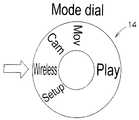
カメラ2の上面には、無線通信用のアンテナ4、レリーズボタン12、モード設定ダイヤル14が設けられている。レリーズボタン12は、合焦箇所の入手を指示したり画像記録開始を指示したり、カメラ2がクライアント側となった場合にサーバ側のデジタルカメラに対して画像送信要求を出す際の指示手段である。レリーズボタン12は、半押しでスイッチS1がオン(焦点合わせ等の撮影準備)、全押しでスイッチS2がオン(レリーズ;画像送信要求指示)となる操作部材である。モード設定ダイヤル14は、図2に示すように、静止画撮影モード(Cam)、動画撮影(ムービー)モード(Mov)、セットアップモード(Setup)、再生モード(Play)、無線通信モード(Wireless)を選択するためのダイヤルである。このモード設定ダイヤル14の構成により、モードとして静止画撮影、動画撮影、無線通信は独立した構成となっている。すなわち、静止画撮影、動画撮影、無線通信はどれかしか選択できないようになっている。
【0020】
カメラ2の一方の側面には、メモリカードスロット92が設けられている。メモリカードスロット92は、スリット状に形成された挿入口で、カメラ2内へメモリカード94(記録媒体)を挿入するためのものである。
【0021】
カメラ2の裏面には、光学ファインダー8、電源スイッチ6、モニタ表示部10、上下左右キー18、メニューボタン20、実行ボタン22、キャンセルボタン24が設けられている。電源スイッチ6は、電源ON/OFF手段である。上下左右キー18は、メニュー選択の際に押圧することによって上下左右に選択肢を動かすためのものである。メニューボタン20は、撮影系モードが選択されている場合には、押すことによって人物(ポートレート)メニュー、風景メニュー、夜景メニュー、モノクロメニューなどの各種メニューを表示させることができる。実行ボタン22は表示したメニューを選択実行するためのボタンである。キャンセルボタン24は、選択を取り消すためのボタンである。
【0022】
モニタ表示部10はカラー液晶表示になっており、CCD36を介して取り込まれる画像やメモリカード94から読み出した再生画像が表示されると共に、モード情報、電池残量警告、撮影日時、標準撮影可能枚数、再生コマ番号、画像送信、画像受信などの各種情報も表示される。各種のメニュー表示、メニューの選択や各メニューにおける各種設定項目の設定等もモニタ表示部10の表示画面を用いて行われる。
【0023】
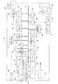
図3は本実施の形態のデジタルカメラ2の構成を示すブロック図である。図3において、信号処理部44、タイミングジェネレータ42、A/D変換部46、ストロボ充電/制御部40、圧縮/伸張部48、カレンダ・時計部50、フレームメモリ52、オンスクリーンディスプレイ60、モータドライバ62、CPU76、システムメモリ78、不揮発性メモリ80、タイマ82、無線通信モジュール84、I/Oインターフェース86、カードインターフェース90は、バス27を介して接続されている。
【0024】
撮影部26には、ズームレンズ29、シャッタ31、アイリス絞り33、フォーカスレンズ35、CCD36が配設されており、さらにズームレンズ29を駆動するズームモータ28、シャッタ31を駆動するシャッタモータ30、アイリス絞り33を駆動するアイリスモータ32、フォーカスレンズ35を駆動するフォーカスモータ34が備えられている。これら各モータ28、30、32、34を駆動するモータドライバ62は、CPU76の制御信号により制御される。光学ユニット29、31、33、35の後方にCCD36が配置される。
【0025】
ズームレンズ29、シャッタ31を通過した光は、アイリス絞り33により光量が調節された後、フォーカスレンズ35を通過してCCD36に入射する。CCD36の受光面には、フォトセンサが平面的に配列されており、CCD36の受光面に結像された被写体像は、各フォトセンサによって入射光量に応じた量の信号電荷に変換される。このようにして蓄積された信号電荷は、タイミングジェネレータ42から供給されるパルスによって、信号電荷に応じた電圧信号として順次読み出される。
【0026】
CCD36は、各フォトセンサの電荷蓄積時間(シャッタースピード)をシャッターゲートパルスによって制御する、いわゆる電子シャッター機能を有している。アイリス絞り33とCCD36の電子シャッターの組み合わせによって露光制御され、CCD36から出力された画像信号は、信号処理部44において信号処理される。
【0027】
信号処理部44は、色分離、ゲイン切換え、γ(ガンマ)処理などの各処理回路を含む。信号処理された後、画像信号はA/D変換部46においてA/D変換される。信号処理、A/D変換はタイミングジェネレータ42から供給されるパルスによって動作する。A/D変換された画像信号は、CPU76によって入力画像信号のレベルが検出され、被写体の輝度情報が取得されて、被写体の合焦状態も検出される。
【0028】
その後、CPU76は、画像信号を、輝度・色差信号生成、シャープネス補正(輪郭補正)、ホワイトバランス補正、ガンマ補正し、輝度信号(Y信号)及び色差信号(Cr、Cb信号)に変換し、システムメモリ78に格納する。
【0029】
システムメモリ78に格納された画像データは、CPU76の指令にしたがって読み出され、フレームメモリ52に格納されてLCD(液晶ディスプレイ)制御部54において表示用の所定方式の信号(例えば、NTSC方式のカラー複合映像信号)に変換される。LCD制御部54では、OSD(オンスクリーンディスプレイ)60からの文字情報を統合する。その後、表示用の信号はLCD58に出力され、バックライト56が点灯してLCD58に表示される。
【0030】
動画撮影の際は、CCD36から出力される画像信号によってシステムメモリ78のデータが定期的に書き換えられ、その画像データから生成される映像信号がLCD58に供給されることにより、CCD36で捉える画像がリアルタイムに動画像として、またはリアルタイムではないが、ほぼ連続した画像としてLCD58に表示される。
【0031】
撮影時は、スイッチ/LED等88の一部であるレリーズボタン12の押し下げ動作により、記録開始指示信号が発せられ、I/Oインターフェース86において該指示信号が受け入れされ、その指示信号に呼応して、記録用の画像データの取り込みが開始される。レリーズボタン12の押し下げに応動する撮影動作によって、システムメモリ78に取り込まれた画像信号は、圧縮/伸張部48において、CPU76からのコマンドにしたがって圧縮処理される。圧縮処理された画像信号は、カードインターフェース90からメモリカード94に記録される。メモリカード94はメモリカードスロット92に差し込まれて所定場所に位置づけられる。再生モード時にはメモリカード94から読み出された画像データが圧縮/伸張部48によって伸張処理され、LCD58に出力される。
【0032】
記録メディアの形態は、メモリカードに限定されず、PCカード、コンパクトフラッシュ、磁気ディスク、光ディスク、光磁気ディスク、メモリスティックなどでもよく、電子的、磁気的、若しくは光学的、又はこれらの組合せによる方式に従って読み書き可能な種々の媒体を用いることができる。使用される媒体に応じた信号処理手段とインターフェースが適用される。異種、同種の記録メディアを問わず、複数の媒体をカメラ2に装着可能な構成にしてもよい。また、画像データを保存する手段は、カメラ本体から分離可能なリムーバブルメディアに限らず、カメラ2に内蔵された記録媒体(内部メモリ)、すなわち本形態ではシステムメモリ78であってもよい。
【0033】
カメラ2には、画像・文字データを他のデジタルカメラやパソコンその他の外部機器と無線で送受信するための無線通信モジュール84及び無線通信モジュール84に接続されたアンテナ4が設けられる。画像・文字データを他のデジタルカメラや外部機器と無線で送受信するときは、モード設定ダイヤル14をWirelessに合わせて、システムメモリ78又はメモリカード94から送信しようとする画像(文字)データを読み出し、送信したり、アンテナ4で受け入れようとする画像・文字データを受信する。無線通信モジュール84は、CPU76からデータの送受が可能になっており、CPU76からバス27を介したコマンドによりスリープが可能であり、スリープの状態では、モータ28、30、32、34の消費電流に対し無視可能な電流値となる。
【0034】
CPU76は本カメラシステムの各回路を統括制御する制御部である。システムメモリ78はROM及びRAMの記憶手段を備え、ROMにはCPU76が処理するプログラム及び制御に必要な各種データ等が格納され、RAMはCPU76が各種の演算処理等を行う際の作業用エリアとして利用される。CPU76は、スイッチ/LED等88から受入する入力信号に基づき、対応する回路の動作を制御するとともに、LCD58の表示制御、AF(オートフォーカス)制御及びAE(オートエクスポージャー:自動露出)制御等を行う。
【0035】
CPU76は、AF評価値の演算やAE演算などの各種演算を行い、その演算結果に基づいてモータドライバ62を制御してフォーカスモータ34を合焦位置に移動させるとともに、アイリスモータ32を制御して適正な絞りに設定し、かつCCD36の電荷蓄積時間を制御する。
【0036】
スイッチ/LED等88は、レリーズボタン12、モード設定ダイヤル14、上下左右キー18などの指示入力手段を含むブロックであり、画像記録時の画素数を指定する手段、電子ズーム機能のON/OFFを切り替える手段、電子ズームの拡大率を操作する手段などを含む。
【0037】
バス27にはストロボ充電/制御部40が接続され、ストロボ充電/制御部40にはストロボ38が接続されていて、ストロボ38使用時にはストロボ充電/制御部40がストロボ38の作動を制御する。
【0038】
バス27には、カレンダ・時計50、不揮発性メモリ80、タイマ82が接続されている。カレンダ・時計50は日付・時間を記録し、不揮発性メモリ80にはカメラ2の機器情報が格納され、タイマ82はタイマ撮影をするためのものである。
【0039】
バッテリ64は各部に電源を供給している。
【0040】
撮影した画像の画像ファイルがメモリカード94に記録されている記録構造を説明する。図4は、メモリカードの記録構造を示す図である。ルート・ディレクトリには、いくつかのサブ・ディレクトリが作成されている。サブ・ディレクトリには、例えば撮影内容別にタイトルをつけることができる。ここでは、001のディレクトリに「Vacation」とつけ、002のディレクトリに「Birthday」とつけている。「Vacation」のディレクトリには、Vacation関連画像の画像ファイル群が作成されており、Vacation関連画像の各画像ファイルにはファイル番号が付けられている。モニタ表示部10に表示されるコマ番号は、例えば、Vacation関連の3番目の画像の場合は、「001−0003」となる。一方、「Birthday」のディレクトリには、Birthday関連画像の画像ファイル群が作成されており、Birthday関連画像の各画像ファイルにはファイル番号が付けられている。なお、ファイル番号は、途中欠番があってもよい。
【0041】
本実施の形態の作用を説明する。
【0042】
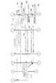
ここでは、デジタルカメラが4台存在し、このうち、画像送信側として機能するカメラ(サーバカメラ)として2台、画像受信側として機能するカメラ(クライアントカメラ)が2台ある場合の例を説明する。図9−図12は、これらクライアントカメラA、クライアントカメラB、サーバカメラC、サーバカメラDの相互の通信のやりとりを示したフローチャートである。クライアントカメラAはアドレス「AAA」を持っており、クライアントカメラBはアドレス「BBB」、、サーバカメラCはアドレス「IJK」、サーバカメラDはアドレス「FGH」をそれぞれ持っている。
【0043】
この例は、クライアントカメラ、サーバカメラ間の通信において、サーバカメラ側で送信しようとする画像を表示しておき、クライアント側のカメラ群の個々のユーザは自分の欲しい画像がサーバカメラに表示されているときに、レリーズボタン12によりサーバカメラへ画像取得要求を送信して画像を送信してもらう内容である。
【0044】
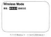
まず、サーバカメラC、Dにおいて、モード設定ダイヤル14をWirelessモードにする(ステップ100、104)。サーバカメラC、Dのモニタ表示部10は図5に示す表示をする。ここで、「画像送信」の機能を選択する(ステップ102、106)。すると、図6のようなサーバカメラの画像送信のモードとなり、ここで表示される画像が送信対象となる。したがって、送信画像の選択は、ここで表示される画像をどれにするかということになる。表示画像は、図4のように格納されているメモリカード94の画像ファイルを選択することによって表示される。図6のモニタ表示部10の画面において、コマ番号を▲、▼によりインクリメント、デクリメントすることにより表示画像を前後させることができる。モニタ表示部10の画面には、表示画像と共にコマ番号や画像ファイルに添付して記録されている撮影年月日も表示させると便利である。画像送信機能を選択後は、サーバカメラC、Dはそれぞれ画像選択タスク、画像送信タスク、探査応答タスクが作動するようになっている。
【0045】
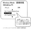
画像受信側のクライアントカメラAでは、モード設定ダイヤル14をWirelessモードにすると、クライアントカメラAのモニタ表示部10は図5に示す表示をする(ステップ120)。ここで、「画像受信」の機能を選択する(ステップ122)。すると、図7のようなクライアントカメラの画像受信のモードとなる。画像受信のモードとなったときは、クライアントカメラAは、周囲で画像送信が可能な状態となっているサーバカメラを探査する(ステップ160、162)。サーバカメラC、サーバカメラDがクライアントカメラAの周囲に存在しているとすると、サーバカメラC、サーバカメラDの探査応答タスクが作動してクライアントカメラAにサーバカメラ応答の信号を送信する(ステップ164、166)。信号送信には、サーバカメラC、Dの各アドレス、及び各サーバカメラC、Dに付与されている機器名称が含まれる。サーバカメラCには、「Hiroshi」という機器名称が設定されている。サーバカメラDには、「Tanaka’s mobile phone」という機器名称が設定されている。機器名称は、ここでは設定方法を詳述しないが、パソコン等からカメラにユーザ設定可能であり、工場出荷時に機種名等が記録されていてもよい。
【0046】
クライアントカメラAでは、探査の結果みつかったサーバカメラのリストが図7のように表示される(ステップ124)。リストには、サーバカメラの応答信号に含まれるサーバカメラのアドレス及び機器名称が表示される。クライアントカメラAのユーザは、見つかったサーバカメラのリストから、接続するカメラを▲、▼により選択する。図7の例では、探査された3つの機器のうち、真ん中に表示されている機器、すなわちサーバカメラC、がセレクトされている。この状態で実行ボタン22を押すと、セレクトされている機器(アドレス「IJK」)が画像送信側として選択される(ステップ124)。
【0047】
ユーザがクライアントカメラAにおいて、接続しようとするサーバカメラを決定すると、クライアントカメラAからサーバカメラCに対して接続要求が送信される(ステップ168)。サーバカメラCは、セッションIDを付与してクライアントカメラAに接続完了を送信する(ステップ170)。セッションIDは、サーバカメラが同時に複数のクライアントカメラから接続された場合に、個々の接続を区別管理するために付与される、接続ごとに唯一のIDである。
【0048】
クライアントカメラからサーバカメラへの接続は、任意のタイミングで、他の接続と全く独立に行うことが可能となっているため、画像を受信しようとするクライアントカメラが複数ある場合は、一斉に同じタイミングでクライアントカメラのモードとなる必要はない。
【0049】
クライアントカメラAとサーバカメラCとの接続が完了すると、クライアントカメラAのユーザは、サーバカメラCにおいて自分が欲しい画像が表示されているときに、画像取得操作(すなわち、画像送信指示操作)を行うことができる。サーバカメラCでは、モニタ表示部10に、画像、コマ番号(ここでは、「xxx−xxxx」)、撮影年月日が表示されている(ステップ108)。この時点で画像取得操作を行った場合を説明する。画像取得操作は、クライアントカメラAにおけるレリーズボタン12の押し下げによるが、これに限定されるものではない。
【0050】
クライアントカメラAにおいて画像取得操作がなされると(ステップ126)、クライアントカメラAからサーバカメラCに画像送信要求が送信される(ステップ172)。サーバカメラCは、その時点でモニタ表示部10に表示されている画像の画像ファイルをクライアントカメラAに送信するが(ステップ174)、送信する際は、セッションIDも送信して間違いなくすでに接続が済んでいるクライアントカメラAに画像を送信する。したがって、ある画像を欲しがるクライアントカメラのユーザが複数存在する場合は、サーバカメラCのユーザは、その画像をサーバカメラに表示しておくだけでよく、個々のクライアントカメラのユーザは、サーバカメラに画像が表示されている間に、画像取得操作(レリーズボタン押し下げ)を行うだけでよい。
【0051】
クライアントカメラAに受信された画像は、クライアントカメラAのモニタ表示部10に表示されると共に図8に示すようなディレクトリ構造でメモリカード94に格納される(ステップ128)。すなわち、クライアントカメラAは、自機種で撮影した画像と、受信した画像とを区別するために、新たなディレクトリ番号のディレクトリを作成し、そこに受信した画像を格納する。新たなディレクトリ番号は、既存のディレクトリ番号の最大値+1となる。新たなディレクトリのディレクトリ名には、新たなディレクトリ番号の他に、画像の送信元であるサーバカメラの名称を記録する。このため、ディレクトリを見れば、その画像群がどのカメラから送信されたものであるかがわかる。名称が長い場合には、その名称の先頭の所定の文字数を記録する。ゆえに、クライアントカメラでは、送信元のサーバカメラごとにディレクトリを作成して、受信した画像を保存することができ、ユーザが画像を管理することを容易にしている。
【0052】
本実施の形態では、図9−図12において、サーバカメラCに対し、クライアントカメラAとクライアントカメラBとから画像送信要求がされる例が表示されている。クライアントカメラAにおいて、画像取得操作(ステップ126)が行われる頃から、クライアントカメラBはサーバカメラCとの接続準備に入っている。クライアントカメラBでは、モード設定ダイヤル14をWirelessモードにすると、クライアントカメラBのモニタ表示部10は図5に示す表示をし(ステップ140)、そこで「画像受信」の機能を選択する(ステップ142)。
【0053】
その後、クライアントカメラBはサーバカメラCと接続を確立する(ステップ176、178、180、182、144、184,186)。接続の詳細な過程は、サーバカメラCとクライアントカメラAとの上述した接続の過程と同様であるので、説明を省略する。
【0054】
クライアントカメラBとサーバカメラCとの接続が完了すると、クライアントカメラBのユーザは、サーバカメラCにおいて自分が欲しい画像が表示されているときに、画像取得操作(すなわち、画像送信指示操作)を行うことができる。サーバカメラCでは、モニタ表示部10に、画像、コマ番号(ここでは、「yyy−yyyy」)、撮影年月日が表示されている(ステップ110)。この時点で画像取得操作を行った場合を説明する。画像取得操作は、クライアントカメラAのときと同様、クライアントカメラBのレリーズボタン12の押し下げによる。
【0055】
クライアントカメラBにおいて画像取得操作がなされると(ステップ146)、クライアントカメラBからサーバカメラCに画像送信要求が送信される(ステップ188)。サーバカメラCは、その時点でモニタ表示部10に表示されている画像の画像ファイルをクライアントカメラBに送信するが(ステップ190)、送信する際は、セッションID(ここでは「bbbb」)も送信して間違いなくすでに接続が済んでいるクライアントカメラBに画像を送信する。
【0056】
クライアントカメラBで受信された画像は、クライアントカメラBのモニタ表示部10に表示されると共に図8と同様なディレクトリ構造でメモリカード94に格納される(ステップ148)。
【0057】
上述のように、図9、図10の流れでは、サーバカメラCに対し、最初は、クライアントカメラAから接続され、その時点でモニタ表示部10に表示されているコマ番号「xxx−xxxx」の画像がクライアントカメラAに送信される。このときは、サーバカメラCはクライアントカメラBからは接続されていない。
【0058】
次に、遅れてその場にやってきたクライアントカメラBのユーザが、クライアントカメラBもサーバカメラCと接続させ、サーバカメラCのユーザの操作によりコマ番号「xxx−xxxx」の次に表示されたコマ番号「yyy−yyyy」の画像をクライアントカメラBは取得している。このとき、クライアントカメラAのユーザは、コマ番号「yyy−yyyy」の画像は特に必要なかったので、画像取得操作を行っていない。
【0059】
次に、図11において、サーバカメラCのユーザは、モニタ表示部10にコマ番号「zzz−zzzz」の画像を表示させる(ステップ112)。表示された画像は、クライアントカメラA、Bの両ユーザ共、欲しがるものだったので、クライアントカメラA、Bから画像取得要求がなされ(ステップ130、150、192、196)、サーバカメラCは、クライアントカメラA、Bに画像を送信している(ステップ194、198)。画像送信に関する詳細な過程は、サーバカメラCとクライアントカメラA又はクライアントカメラBとの上述した画像送信の過程と同様であるので、説明を省略する。
【0060】
クライアントカメラA、Bに受信された画像は、クライアントカメラA、Bのモニタ表示部10に表示されると共に図8と同様なディレクトリ構造でメモリカード94に格納される(ステップ132、152)。
【0061】
なお、この実施の形態では、同報的に2回画像をクライアントカメラ(AとB)に送信しているが、ブロードキャストが可能な通信インターフェースでは、1回の送信で済ませることができる。
【0062】
次に、サーバカメラCのユーザは、コマ番号「www−wwww」をモニタ表示部10に表示させるが(ステップ114)、この画像は、クライアントカメラA、Bの両ユーザ共、必要ないものであるため、画像取得操作は行われず、スキップされている。
【0063】
次に、サーバカメラCのユーザは、コマ番号「vvv−vvvv」をモニタ表示部10に表示させるが(ステップ116)、この画像はクライアントカメラAのユーザのみが欲しい画像であったため、クライアントカメラBのユーザは画像取得操作は行わずに、クライアントカメラAからのみ画像取得要求がサーバカメラCに対してなされ(ステップ134、200)、サーバカメラCは、クライアントカメラAに画像を送信している(ステップ202)。画像送信に関する詳細な過程は、サーバカメラCとクライアントカメラA又はクライアントカメラBとの上述した画像送信の過程と同様であるので、説明を省略する。
【0064】
クライアントカメラAで受信された画像は、クライアントカメラAのモニタ表示部10に表示されると共に図8と同様なディレクトリ構造でメモリカード94に格納される(ステップ136)。
【0065】
ここで、図12において、クライアントカメラAのユーザは、自分のカメラで新たに画像を撮影する必要が発生したため、自分のカメラのモードをモード設定ダイヤル14を動かして「Cam」モードにする(ステップ138)。その際、クライアントカメラAからサーバカメラCに対し、当該セッションIDの接続を切断する要求が送られ(ステップ204)、サーバカメラCからクライアントカメラAに切断完了の通知が送られる(ステップ206)。なお、サーバカメラCとクライアントカメラBとの接続は独立しているため、この時点でクライアントカメラBはサーバカメラCに対し、引き続き画像の取得が可能となっている。
【0066】
次に、サーバカメラCのユーザは、当初、クライアントカメラBのユーザがいないときにクライアントカメラAに送ってしまった画像(コマ番号「xxx−xxxx」)を思い出したため、このコマ番号の画像を再びモニタ表示部10に表示させて(ステップ118)、クライアントカメラBのユーザに示したところ、クライアントカメラBのユーザはこのコマ番号の画像を欲しいと思ったため、画像送信要求をサーバカメラCに送信し(ステップ208)、サーバカメラCは当該画像をクライアントカメラBに送信している(ステップ210)。クライアントカメラBが受信した画像は、クライアントカメラBのモニタ表示部10に表示されると共に図8と同様なディレクトリ構造でメモリカード94に格納される(ステップ154)。
【0067】
その後、クライアントカメラBのユーザは電源切断操作を行い(ステップ156)、サーバカメラCに接続の切断要求を送り(ステップ212)、サーバカメラCからクライアントカメラBに切断完了の通知が送られる(ステップ214)。その後、クライアントカメラBの電源が切断される(ステップ158)。
【0068】
以上、説明したとおり、本実施の形態では、1つの画像送信側カメラに対し、複数の受信側カメラが存在する場合において、個々の受信側カメラのユーザが欲しがる画像が異なる場合、非常に簡単な操作で個々の受信側カメラのユーザが欲しい画像のみをそのユーザのカメラで受信することが可能となる。もちろん、受信側カメラは1つでもよい。
【0069】
図9−図12において、サーバカメラDは画像送信モードとなったものの、結果的にクライアントカメラA、Bに画像送信する機会がなかったサーバカメラである。
【0070】
なお、サーバカメラCにおいて、画像を選択中(すなわち、図6において▲、▼を押し下げして画像が表示されるまで)の間は、送信されるべき画像が不定であるとして、クライアントカメラからの画像送信要求に対してサーバカメラCがエラーを返してもよいし、直前に再生されていた画像を送信してもよい。エラーを返した場合は、クライアントカメラにおいて、ユーザにその旨の表示を行えばよい。
【0071】
また、表示、送信される画像が静止画でも動画でも良いのは言うまでもない。また、本実施例では、カメラ同士が直接無線通信で通信を行っているが、この形態に限るものでなく、複数のカメラが無線を介して、いったんアクセスポイントを経由しても構わないし、有線でネットワーク接続されても構わない。
【0072】
【発明の効果】
本発明によれば、クライアント側のユーザは、サーバ側から受信したい画像をPULL形式で取得することができるので、サーバ側でいちいちその都度送信先のアドレスを指定、確認した上で画像を送信するという手間が省ける。クライアント側が複数の場合は、この手間が省けることの効果は特に大きい。
【図面の簡単な説明】
【図1】画像通信装置であるデジタルカメラの背面斜視図。
【図2】モード設定ダイヤルの拡大図。
【図3】デジタルカメラの構成を示すブロック図。
【図4】メモリカードの記録構造を示す図。
【図5】サーバカメラにおいて、モード設定ダイヤルをWirelessモードにしたときのサーバカメラのモニタ表示部の表示図。
【図6】図5の表示において画像送信機能を選択して画像が表示されたときのモニタ表示部の図。
【図7】図5の表示において画像受信機能を選択して探査の結果みつかったサーバカメラのリストをモニタ表示部で表示したときの図。
【図8】受信画像がメモリカードに格納されるときのディレクトリ構造を示した図。
【図9】クライアントカメラA、クライアントカメラB、サーバカメラC、サーバカメラDの相互の通信のやりとりを示したフローチャート。
【図10】クライアントカメラA、クライアントカメラB、サーバカメラC、サーバカメラDの相互の通信のやりとりを示したフローチャートで、図9の続きの流れの図。
【図11】クライアントカメラA、クライアントカメラB、サーバカメラC、サーバカメラDの相互の通信のやりとりを示したフローチャートで、図10の続きの流れの図。
【図12】クライアントカメラA、クライアントカメラB、サーバカメラC、サーバカメラDの相互の通信のやりとりを示したフローチャートで、図11の続きの流れの図。
【符号の説明】
2…デジタルカメラ、4…アンテナ、10…モニタ表示部、12…レリーズボタン、14…モード設定ダイヤル、22…実行ボタン、58…LCD、76…CPU、84…無線通信モジュール、86…I/Oインターフェース、88…スイッチ/LED、90…カードインターフェース、92…メモリカードスロット、94…メモリカード[0001]
BACKGROUND OF THE INVENTION
The present invention relates to an image communication apparatus and method for performing wireless communication in a client-to-server format or a master-to-slave format.
[0002]
[Prior art]
In recent years, digital cameras have become widespread, but it has been proposed to provide a wireless interface and an antenna for the digital cameras to perform wireless communication with other digital cameras and external communication devices. In particular, there are many needs to send images taken with a digital camera to other people's digital cameras and external communication devices. When traveling with multiple people, each with a digital camera, it is often desirable to store images taken with their own digital camera in a digital camera owned by another person.
[0003]
Patent Document 1 discloses a so-called PUSH format camera and method for displaying or selecting an image to be transmitted by a master side (client side) camera that controls communication and transmitting it to a slave side (server side) camera on the receiving side. Are disclosed.
[0004]
In the method disclosed in Japanese Patent Application Laid-Open No. 2005-228867, when the transmission side and the reception side have a one-to-one relationship, it is easy to understand and practical on the user interface, but in the case of transmitting a plurality of images to a plurality of reception side cameras. In the case where the image desired to be transmitted is different for each receiving camera, the following problem occurs. That is, the user of the transmitting camera selects the image to be transmitted, confirms whether or not the user of each receiving camera wants the image, and sends the user's camera that wanted the image to each destination. As a result, an image transmission operation must be performed. When traveling with multiple people as described above, it is cumbersome to perform such an operation individually on the sending side and the receiving side, and when sending different images to multiple people, the destination for each image is different. In contrast, since there are a plurality of destination addresses, it becomes more complicated.
[0005]
[Patent Document 1]
Japanese Patent Laid-Open No. 9-284696
[0006]
[Problems to be solved by the invention]
In consideration of the above circumstances, the present invention allows users of individual digital cameras on the image receiving side to individually select images desired on the image transmitting side when exchanging images among a plurality of image communication apparatuses, particularly digital cameras. An object of the present invention is to provide an image communication apparatus and method that enable pulling from a digital camera.
[0007]
[Means for Solving the Problems]
Book inventionFirst side of Is an image communication apparatus capable of communicating with another image communication apparatus in a server-to-client format, and includes an image display means for displaying a recorded image, and an image displayed by the image display means. Image communication comprising: selection means for selecting an image to be transmitted; and transmission means for transmitting an image selected by the selection means when receiving an image transmission request from one or more image communication apparatuses on the client side Device.
[0008]
Book inventionFirst side of According to the present invention, an image communication apparatus capable of communicating with another image communication apparatus in a server-to-client format, which is an image communication apparatus that functions as a server side, displays an image on an image display means, and displays the image. The image to be transmitted is selected by the selection means, and the image selected by the selection means is transmitted when the transmission means receives an image transmission request from one or more image communication devices on the client side. .
[0009]
Accordingly, the user of the image communication device on the image transmission side can transmit the selected image to the image communication device on the client side in response to a transmission request from the user of the image communication device on the client side.
[0010]
Book inventionSecond side of Is an image communication apparatus capable of communicating with another image communication apparatus in a server-to-client format, and when an image to be transmitted is selected from among images displayed on the server-side image communication apparatus. A request transmission means capable of transmitting an image transmission request to the server-side image communication apparatus so as to transmit an image, and an instruction means for instructing transmission of the image transmission request to the server-side image communication apparatus. An image communication device.
[0011]
Book inventionSecond side of According to the present invention, an image communication apparatus capable of communicating with another image communication apparatus in a server-to-client format, the image communication apparatus functioning as a client side, and an image displayed on the server side image communication apparatus When an image to be transmitted is selected, the instruction unit instructs the image transmission apparatus on the server side to transmit the image transmission request to the server side image communication apparatus, and the request transmission unit sends the image transmission request to the image communication apparatus on the server side. Then, the image communication apparatus on the server side transmits the image to the image communication apparatus on the client side. Then, the image communication apparatus on the client side receives the image.
[0012]
Thereby, the user of the image communication device on the image receiving side can acquire the image to be received from the image communication device on the server side.
[0013]
Book inventionThird side of Is an image communication method capable of communicating images in a server-to-client format, in which an image is displayed on the server side, and the server side attempts to transmit the displayed image to the client side. The step of selecting an image, the step of instructing the client side to transmit an image transmission request to the server side to transmit the image, and the image transmission from the client side to the server side so as to transmit the image from the server side to the client side An image communication method comprising: a step of transmitting a request; and a step of transmitting the selected image from the server side to the client side when the server side receives an image transmission request from the client side.
[0014]
Book inventionThird side of According to the above, after displaying and selecting an image on the server side, an image transmission request is transmitted to the server side according to an instruction from the client side, and the image is transmitted from the server side to the client side. As a result, the client side receives the image.
[0015]
Thereby, the user on the client side can acquire the image to be received from the server side.
[0016]
DETAILED DESCRIPTION OF THE INVENTION
Hereinafter, embodiments of the present invention will be described in detail with reference to the accompanying drawings.
[0017]
FIG. 1 is a rear perspective view of a
[0018]
The
[0019]
On the upper surface of the
[0020]
A
[0021]
On the back surface of the
[0022]
The
[0023]
FIG. 3 is a block diagram showing the configuration of the
[0024]
The photographing
[0025]
The light that has passed through the
[0026]
The
[0027]
The
[0028]
Thereafter, the
[0029]
The image data stored in the
[0030]
At the time of moving image shooting, data in the
[0031]
At the time of photographing, a recording start instruction signal is issued by the depressing operation of the
[0032]
The form of the recording medium is not limited to a memory card, and may be a PC card, a compact flash, a magnetic disk, an optical disk, a magneto-optical disk, a memory stick, etc., and a system based on electronic, magnetic, optical, or a combination thereof Accordingly, various media that can be read and written can be used. A signal processing means and an interface corresponding to the medium to be used are applied. A configuration may be adopted in which a plurality of media can be mounted on the
[0033]
The
[0034]
The
[0035]
The
[0036]
A switch / LED 88 is a block including instruction input means such as a
[0037]
A strobe charging /
[0038]
To the
[0039]
The
[0040]
A recording structure in which an image file of a photographed image is recorded on the
[0041]
The operation of the present embodiment will be described.
[0042]
Here, an example will be described in which there are four digital cameras, of which two cameras (server cameras) function as the image transmission side and two cameras (client cameras) function as the image reception side. . FIG. 9 to FIG. 12 are flowcharts showing the communication between the client camera A, client camera B, server camera C, and server camera D. Client camera A has an address “AAA”, client camera B has an address “BBB”, server camera C has an address “IJK”, and server camera D has an address “FGH”.
[0043]
In this example, in the communication between the client camera and the server camera, the image to be transmitted is displayed on the server camera side, and each user in the camera group on the client side displays the desired image on the server camera. The
[0044]
First, in the server cameras C and D, the
[0045]
In the client camera A on the image receiving side, when the
[0046]
In the client camera A, a list of server cameras found as a result of the search is displayed as shown in FIG. 7 (step 124). The list displays the server camera address and device name included in the response signal of the server camera. The user of the client camera A selects the camera to be connected from the list of found server cameras with ▲ and ▼. In the example of FIG. 7, the device displayed in the middle of the three devices searched, that is, the server camera C is selected. When the execute
[0047]
When the user determines the server camera to be connected in the client camera A, a connection request is transmitted from the client camera A to the server camera C (step 168). The server camera C gives a session ID and transmits a connection completion to the client camera A (step 170). The session ID is a unique ID for each connection that is given to distinguish and manage individual connections when the server camera is connected from a plurality of client cameras at the same time.
[0048]
The connection from the client camera to the server camera can be made at any timing and completely independently of the other connections, so if there are multiple client cameras trying to receive an image, the same timing at the same time There is no need to enter the client camera mode.
[0049]
When the connection between the client camera A and the server camera C is completed, the user of the client camera A performs an image acquisition operation (that is, an image transmission instruction operation) when an image that the user wants is displayed on the server camera C. be able to. In the server camera C, an image, a frame number (here, “xxx-xxxx”), and a shooting date are displayed on the monitor display unit 10 (step 108). A case where an image acquisition operation is performed at this time will be described. The image acquisition operation is performed by pressing the
[0050]
When an image acquisition operation is performed in the client camera A (step 126), an image transmission request is transmitted from the client camera A to the server camera C (step 172). The server camera C transmits the image file of the image currently displayed on the
[0051]
The image received by the client camera A is displayed on the
[0052]
In this embodiment, in FIGS. 9 to 12, an example in which an image transmission request is made from the client camera A and the client camera B to the server camera C is displayed. In the client camera A, the client camera B has been ready for connection with the server camera C since the image acquisition operation (step 126) is performed. In the client camera B, when the
[0053]
Thereafter, the client camera B establishes a connection with the server camera C (
[0054]
When the connection between the client camera B and the server camera C is completed, the user of the client camera B performs an image acquisition operation (that is, an image transmission instruction operation) when the desired image is displayed on the server camera C. be able to. In the server camera C, an image, a frame number (here, “yyy-yyyy”), and a shooting date are displayed on the monitor display unit 10 (step 110). A case where an image acquisition operation is performed at this time will be described. The image acquisition operation is performed by depressing the
[0055]
When an image acquisition operation is performed in the client camera B (step 146), an image transmission request is transmitted from the client camera B to the server camera C (step 188). The server camera C transmits the image file of the image currently displayed on the
[0056]
The image received by the client camera B is displayed on the
[0057]
As described above, in the flow of FIGS. 9 and 10, the server camera C is initially connected from the client camera A and the frame number “xxx-xxxx” displayed on the
[0058]
Next, the user of the client camera B who came to the spot with a delay connects the client camera B to the server camera C, and the frame displayed next to the frame number “xxx-xxxx” by the user of the server camera C is operated. The client camera B has acquired the image of the number “yyy-yyyy”. At this time, the user of the client camera A does not perform the image acquisition operation because the image of the frame number “yyy-yyyy” is not particularly required.
[0059]
Next, in FIG. 11, the user of the server camera C displays an image of the frame number “zzz-zzz” on the monitor display unit 10 (step 112). Since the displayed images were desired by both users of the client cameras A and B, an image acquisition request is made from the client cameras A and B (
[0060]
The images received by the client cameras A and B are displayed on the
[0061]
In this embodiment, the image is transmitted to the client cameras (A and B) twice in the same broadcast. However, in the communication interface capable of broadcasting, the image can be transmitted once.
[0062]
Next, the user of the server camera C displays the frame number “www-www” on the monitor display unit 10 (step 114), but this image is unnecessary for both the users of the client cameras A and B. Therefore, the image acquisition operation is not performed and is skipped.
[0063]
Next, the user of the server camera C displays the frame number “vvv-vvvv” on the monitor display unit 10 (step 116). Since this image is an image that only the user of the client camera A wants, the client camera B The image acquisition request is made to the server camera C only from the client camera A without performing the image acquisition operation (
[0064]
The image received by the client camera A is displayed on the
[0065]
Here, in FIG. 12, since the user of the client camera A needs to take a new image with his / her camera, the
[0066]
Next, since the user of the server camera C initially remembered the image (frame number “xxx-xxxx”) that was sent to the client camera A when there was no user of the client camera B, the image of this frame number was again displayed. When displayed on the monitor display unit 10 (step 118) and shown to the user of the client camera B, the user of the client camera B wants an image of this frame number, and therefore sends an image transmission request to the server camera C. (Step 208), the server camera C transmits the image to the client camera B (step 210). The image received by the client camera B is displayed on the
[0067]
Thereafter, the user of the client camera B performs a power-off operation (step 156), sends a disconnection request to the server camera C (step 212), and a notification of disconnection completion is sent from the server camera C to the client camera B (step). 214). Thereafter, the power source of the client camera B is turned off (step 158).
[0068]
As described above, in the present embodiment, when there are a plurality of receiving cameras with respect to one image transmitting camera, the images desired by the users of the individual receiving cameras are very different. Only an image desired by the user of each receiving camera can be received by the user's camera with a simple operation. Of course, one receiving camera may be used.
[0069]
9 to 12, the server camera D is a server camera that is in the image transmission mode, but as a result, has no opportunity to transmit images to the client cameras A and B.
[0070]
Note that while the server camera C is selecting an image (that is, until the image is displayed by pressing ▲ and ▼ in FIG. 6), it is assumed that the image to be transmitted is indefinite and In response to the image transmission request, the server camera C may return an error, or an image reproduced immediately before may be transmitted. If an error is returned, the client camera may display that fact to the user.
[0071]
Needless to say, the displayed and transmitted image may be a still image or a moving image. Further, in this embodiment, the cameras communicate directly with each other by wireless communication. However, the present invention is not limited to this mode, and a plurality of cameras may pass through an access point via wireless communication, or may be wired. You may be connected to the network.
[0072]
【The invention's effect】
According to the present invention, the user on the client side can acquire an image desired to be received from the server side in the PULL format, so that the server side designates and confirms the destination address each time and transmits the image. You can save the trouble. When there are a plurality of clients, the effect of saving this effort is particularly great.
[Brief description of the drawings]
FIG. 1 is a rear perspective view of a digital camera that is an image communication apparatus.
FIG. 2 is an enlarged view of a mode setting dial.
FIG. 3 is a block diagram illustrating a configuration of a digital camera.
FIG. 4 is a diagram showing a recording structure of a memory card.
FIG. 5 is a display diagram of the monitor display unit of the server camera when the mode setting dial is set to the wireless mode in the server camera.
6 is a diagram of a monitor display unit when an image is displayed by selecting an image transmission function in the display of FIG.
7 is a diagram when a list of server cameras found as a result of search by selecting an image reception function in the display of FIG. 5 is displayed on a monitor display unit.
FIG. 8 is a diagram showing a directory structure when a received image is stored in a memory card.
FIG. 9 is a flowchart showing the communication between the client camera A, the client camera B, the server camera C, and the server camera D.
FIG. 10 is a flowchart showing communication exchanges among the client camera A, the client camera B, the server camera C, and the server camera D, and is a continuation of FIG.
FIG. 11 is a flowchart showing a communication exchange between the client camera A, the client camera B, the server camera C, and the server camera D, and is a continuation of FIG.
FIG. 12 is a flowchart showing the communication between the client camera A, the client camera B, the server camera C, and the server camera D, and is a continuation of FIG.
[Explanation of symbols]
2 ... Digital camera, 4 ... Antenna, 10 ... Monitor display, 12 ... Release button, 14 ... Mode setting dial, 22 ... Execution button, 58 ... LCD, 76 ... CPU, 84 ... Wireless communication module, 86 ... I / O Interface, 88 ... Switch / LED, 90 ... Card interface, 92 ... Memory card slot, 94 ... Memory card
Claims (4)
Translated fromJapanese記録されている画像を表示する画像表示手段と、
前記画像表示手段で表示される画像のうち、送信しようとする画像を仮選択する仮選択手段と、
クライアント側の1以上のデジタルカメラからの画像送信要求を受けた場合に前記仮選択手段によって各々仮選択された画像を個別のクライアント側へ送信する送信手段と、からなるデジタルカメラ。A digital camera having a server-side function capable of communicating with anumber of otherdigital cameras ina server-to-client formatcapable of one-to-many communication ,
Image display means for displaying recorded images;
Temporary selection means fortemporarily selecting an image to be transmitted among the images displayed by the image display means;
Transmitting means for transmittingeach temporary selected image by theprovisional selecting unit when receiving an image transmission request from the client side of the one or moredigital camerasto individual client,the digital camera comprising a.
サーバ側のデジタルカメラにおいて表示される画像のうち、サーバ側において送信しようとする画像が各々仮選択された場合に、画像送信するようサーバ側のデジタルカメラへ画像送信要求を送信することができる要求送信手段と、
前記画像送信要求をサーバ側のデジタルカメラへ送信することを指示する指示手段と、からなるデジタルカメラ。A digital camera having a client-side function capable of communicating with anumber of otherdigital cameras ina server-to-client formatcapable of one-to-many communication ,
Among the images displayed inthe digital camera server, requests that can be sent if the image to be transmittedat the server side isrespectively provisionally selected, the image transmission request to the server side of thedigital camera to the image transmission A transmission means;
Adigital camera comprising: instruction means for instructing transmission of the image transmission request to the server-sidedigital camera ;
サーバ側において画像を表示するステップと、
サーバ側において、前記表示される画像のうち、クライアント側へ送信しようとする画像を各々仮選択するステップと、
クライアント側において、画像送信するようサーバ側に画像送信要求を送信することを指示するステップと、
サーバ側からクライアント側へ画像送信するよう、クライアント側からサーバ側へ画像送信要求を送信するステップと、
サーバ側においてクライアント側からの画像送信要求を受けた場合に前記仮選択された画像をサーバ側からクライアント側に送信するステップと、からなる画像通信方法。An image communication method capable of communicating imagesbetween digital cameras ina server-to-client formatcapable of one-to-many communication ,
Displaying an image on the server side;
On the server side, among the displayed images,temporarily selectingeach image to be transmitted to the client side;
Instructing the client side to send an image transmission request to the server side to send an image;
Transmitting an image transmission request from the client side to the server side so as to transmit the image from the server side to the client side;
And a step of transmitting thetemporarily selected image from the server side to the client side when receiving an image transmission request from the client side on the server side.
Priority Applications (3)
| Application Number | Priority Date | Filing Date | Title |
|---|---|---|---|
| JP2002280265AJP4085255B2 (en) | 2002-09-26 | 2002-09-26 | Digital camera and image communication method |
| EP20030256007EP1404108A1 (en) | 2002-09-26 | 2003-09-24 | Image communication apparatus and method for transmitting images on request |
| US10/670,427US7573503B2 (en) | 2002-09-26 | 2003-09-25 | Image communication apparatus and method |
Applications Claiming Priority (1)
| Application Number | Priority Date | Filing Date | Title |
|---|---|---|---|
| JP2002280265AJP4085255B2 (en) | 2002-09-26 | 2002-09-26 | Digital camera and image communication method |
Publications (3)
| Publication Number | Publication Date |
|---|---|
| JP2004120276A JP2004120276A (en) | 2004-04-15 |
| JP2004120276A5 JP2004120276A5 (en) | 2005-09-08 |
| JP4085255B2true JP4085255B2 (en) | 2008-05-14 |
Family
ID=31973295
Family Applications (1)
| Application Number | Title | Priority Date | Filing Date |
|---|---|---|---|
| JP2002280265AExpired - LifetimeJP4085255B2 (en) | 2002-09-26 | 2002-09-26 | Digital camera and image communication method |
Country Status (3)
| Country | Link |
|---|---|
| US (1) | US7573503B2 (en) |
| EP (1) | EP1404108A1 (en) |
| JP (1) | JP4085255B2 (en) |
Families Citing this family (35)
| Publication number | Priority date | Publication date | Assignee | Title |
|---|---|---|---|---|
| JP3927140B2 (en)* | 2003-03-28 | 2007-06-06 | 株式会社東芝 | Wireless communication device and image providing method using the same |
| JP2005136691A (en)* | 2003-10-30 | 2005-05-26 | Fuji Photo Film Co Ltd | Image managing system |
| JP5055686B2 (en) | 2004-05-13 | 2012-10-24 | ソニー株式会社 | Imaging system, imaging apparatus, and imaging method |
| US20060125928A1 (en)* | 2004-12-10 | 2006-06-15 | Eastman Kodak Company | Scene and user image capture device and method |
| US20060187230A1 (en)* | 2005-01-31 | 2006-08-24 | Searete Llc | Peripheral shared image device sharing |
| US20060190968A1 (en)* | 2005-01-31 | 2006-08-24 | Searete Llc, A Limited Corporation Of The State Of The State Of Delaware | Sharing between shared audio devices |
| US8606383B2 (en)* | 2005-01-31 | 2013-12-10 | The Invention Science Fund I, Llc | Audio sharing |
| US9910341B2 (en) | 2005-01-31 | 2018-03-06 | The Invention Science Fund I, Llc | Shared image device designation |
| US20060171603A1 (en)* | 2005-01-31 | 2006-08-03 | Searete Llc, A Limited Liability Corporation Of The State Of Delaware | Resampling of transformed shared image techniques |
| US9489717B2 (en)* | 2005-01-31 | 2016-11-08 | Invention Science Fund I, Llc | Shared image device |
| US9082456B2 (en) | 2005-01-31 | 2015-07-14 | The Invention Science Fund I Llc | Shared image device designation |
| US8902320B2 (en) | 2005-01-31 | 2014-12-02 | The Invention Science Fund I, Llc | Shared image device synchronization or designation |
| US20060221197A1 (en)* | 2005-03-30 | 2006-10-05 | Jung Edward K | Image transformation estimator of an imaging device |
| US9124729B2 (en) | 2005-01-31 | 2015-09-01 | The Invention Science Fund I, Llc | Shared image device synchronization or designation |
| US20060170956A1 (en)* | 2005-01-31 | 2006-08-03 | Jung Edward K | Shared image devices |
| US20070236505A1 (en)* | 2005-01-31 | 2007-10-11 | Searete Llc, A Limited Liability Corporation Of The State Of Delaware | Resampling of transformed shared image techniques |
| US7920169B2 (en)* | 2005-01-31 | 2011-04-05 | Invention Science Fund I, Llc | Proximity of shared image devices |
| US20060174203A1 (en)* | 2005-01-31 | 2006-08-03 | Searete Llc, A Limited Liability Corporation Of The State Of Delaware | Viewfinder for shared image device |
| US9001215B2 (en) | 2005-06-02 | 2015-04-07 | The Invention Science Fund I, Llc | Estimating shared image device operational capabilities or resources |
| US10003762B2 (en) | 2005-04-26 | 2018-06-19 | Invention Science Fund I, Llc | Shared image devices |
| US9819490B2 (en) | 2005-05-04 | 2017-11-14 | Invention Science Fund I, Llc | Regional proximity for shared image device(s) |
| US7697827B2 (en) | 2005-10-17 | 2010-04-13 | Konicek Jeffrey C | User-friendlier interfaces for a camera |
| JP4797674B2 (en)* | 2006-02-13 | 2011-10-19 | ソニー株式会社 | Information processing apparatus and method, and program |
| JP4693651B2 (en)* | 2006-02-20 | 2011-06-01 | キヤノン株式会社 | Imaging apparatus and control method thereof |
| JP4878218B2 (en)* | 2006-06-02 | 2012-02-15 | キヤノン株式会社 | Imaging apparatus having communication function, control method thereof, and program |
| US20090174781A1 (en)* | 2008-01-07 | 2009-07-09 | Panasonic Corporation | Electronic equipment and image pickup apparatus |
| US8130275B2 (en) | 2008-06-13 | 2012-03-06 | Nintendo Co., Ltd. | Information-processing apparatus, and storage medium storing a photographing application launch program executed by information-processing apparatus |
| JP4181211B1 (en) | 2008-06-13 | 2008-11-12 | 任天堂株式会社 | Information processing apparatus and startup program executed therein |
| JP5084640B2 (en) | 2008-06-30 | 2012-11-28 | キヤノン株式会社 | Data receiving apparatus, data transmitting apparatus, control method and program thereof |
| JPWO2010038296A1 (en) | 2008-10-01 | 2012-02-23 | 任天堂株式会社 | Information processing apparatus, information processing system, start program, and storage medium storing the same |
| US20100281073A1 (en)* | 2009-04-29 | 2010-11-04 | Cloutier Robert P | Sequence preserving method for transferring and sharing images |
| JP5554218B2 (en) | 2009-12-14 | 2014-07-23 | パナソニック株式会社 | Electronic equipment, communication system |
| JP6032987B2 (en)* | 2012-07-24 | 2016-11-30 | オリンパス株式会社 | Image output device and method of operating image output device |
| CN103902632B (en)* | 2012-12-31 | 2018-01-02 | 华为技术有限公司 | The method, apparatus and electronic equipment of file system are built in key assignments storage system |
| CN106803939A (en)* | 2017-03-02 | 2017-06-06 | 东方网力科技股份有限公司 | Video monitoring system and its control method |
Family Cites Families (14)
| Publication number | Priority date | Publication date | Assignee | Title |
|---|---|---|---|---|
| US5717496A (en)* | 1992-11-19 | 1998-02-10 | Olympus Optical Co., Ltd. | Electronic imaging apparatus |
| US5742840A (en)* | 1995-08-16 | 1998-04-21 | Microunity Systems Engineering, Inc. | General purpose, multiple precision parallel operation, programmable media processor |
| JPH09284696A (en) | 1996-02-17 | 1997-10-31 | Casio Comput Co Ltd | Electronic still camera and communication method between electronic still cameras |
| US6188431B1 (en)* | 1996-02-17 | 2001-02-13 | Casio Computers Co., Ltd. | Electronic still camera and method for communication between electronic still cameras |
| US20040051785A1 (en)* | 1997-06-06 | 2004-03-18 | Nikon Corporation | Electronic camera having a communication function |
| JP3882182B2 (en) | 1997-11-27 | 2007-02-14 | 富士フイルムホールディングス株式会社 | Image display device, camera, and image communication system |
| JP4352471B2 (en)* | 1998-02-19 | 2009-10-28 | ソニー株式会社 | Communication system and communication method |
| US6567122B1 (en) | 1998-03-18 | 2003-05-20 | Ipac Acquisition Subsidiary I | Method and system for hosting an internet web site on a digital camera |
| JP3652552B2 (en) | 1999-07-23 | 2005-05-25 | パナソニック コミュニケーションズ株式会社 | Digital camera and setting method thereof |
| US7468744B2 (en)* | 2000-03-06 | 2008-12-23 | Sony Corporation | System and method for automatically transferring data from an electronic camera |
| JP4560176B2 (en) | 2000-06-14 | 2010-10-13 | キヤノン株式会社 | Imaging apparatus and control method thereof |
| GB0118436D0 (en)* | 2001-07-27 | 2001-09-19 | Hewlett Packard Co | Synchronised cameras with auto-exchange |
| JP4629929B2 (en) | 2001-08-23 | 2011-02-09 | 株式会社リコー | Digital camera system and control method thereof |
| US7136094B2 (en)* | 2002-02-22 | 2006-11-14 | Hewlett-Packard Development Company, L.P. | Share link between image capturing devices |
- 2002
- 2002-09-26JPJP2002280265Apatent/JP4085255B2/ennot_activeExpired - Lifetime
- 2003
- 2003-09-24EPEP20030256007patent/EP1404108A1/ennot_activeCeased
- 2003-09-25USUS10/670,427patent/US7573503B2/ennot_activeExpired - Lifetime
Also Published As
| Publication number | Publication date |
|---|---|
| US20040080653A1 (en) | 2004-04-29 |
| EP1404108A1 (en) | 2004-03-31 |
| JP2004120276A (en) | 2004-04-15 |
| US7573503B2 (en) | 2009-08-11 |
Similar Documents
| Publication | Publication Date | Title |
|---|---|---|
| JP4085255B2 (en) | Digital camera and image communication method | |
| US7783190B2 (en) | Image pick-up apparatus with a multi-area AF function | |
| JP4158304B2 (en) | Image reproduction method and apparatus, and electronic camera | |
| US20030214589A1 (en) | Photographing method and camera device equipped with temporary photographing | |
| JP2002010133A (en) | Camera device | |
| JP4333394B2 (en) | Camera device, imaging method and program thereof | |
| JP2009199586A (en) | Information processing apparatus and control method thereof | |
| JP2001211421A (en) | Image management method and device, and electronic camera | |
| JP4144144B2 (en) | Image recording method and apparatus | |
| JP4652368B2 (en) | Electronic equipment, image display program | |
| US20050117030A1 (en) | Digital photographing apparatus and file management method thereof | |
| JP2004165780A (en) | Electronic camera | |
| JP2002223403A (en) | Electronic camera | |
| JP4238448B2 (en) | Electronic camera | |
| JP2009141978A (en) | Camera device, through image display method and program thereof | |
| JP2002344802A (en) | Camera and method for changing its mode | |
| JP5109996B2 (en) | Camera device, through image display method and program thereof | |
| JP4766690B2 (en) | Playback device, program, and storage medium | |
| JP2005117114A (en) | Electronic camera and motion image data processing system | |
| JP4284467B2 (en) | Imaging apparatus and image data transmission / reception method | |
| JP2012253797A (en) | Camera device and through image display method | |
| JP4868001B2 (en) | Camera device, through image display method and program thereof | |
| JP3997970B2 (en) | Camera device | |
| JP2006025004A (en) | Imaging device and image reproducing apparatus | |
| JP2004312299A (en) | Digital camera |
Legal Events
| Date | Code | Title | Description |
|---|---|---|---|
| A521 | Request for written amendment filed | Free format text:JAPANESE INTERMEDIATE CODE: A523 Effective date:20050316 | |
| A621 | Written request for application examination | Free format text:JAPANESE INTERMEDIATE CODE: A621 Effective date:20050316 | |
| A711 | Notification of change in applicant | Free format text:JAPANESE INTERMEDIATE CODE: A712 Effective date:20061208 | |
| A977 | Report on retrieval | Free format text:JAPANESE INTERMEDIATE CODE: A971007 Effective date:20071101 | |
| A131 | Notification of reasons for refusal | Free format text:JAPANESE INTERMEDIATE CODE: A131 Effective date:20071106 | |
| A521 | Request for written amendment filed | Free format text:JAPANESE INTERMEDIATE CODE: A523 Effective date:20071225 | |
| TRDD | Decision of grant or rejection written | ||
| A01 | Written decision to grant a patent or to grant a registration (utility model) | Free format text:JAPANESE INTERMEDIATE CODE: A01 Effective date:20080123 | |
| A61 | First payment of annual fees (during grant procedure) | Free format text:JAPANESE INTERMEDIATE CODE: A61 Effective date:20080205 | |
| FPAY | Renewal fee payment (event date is renewal date of database) | Free format text:PAYMENT UNTIL: 20110228 Year of fee payment:3 | |
| R150 | Certificate of patent or registration of utility model | Free format text:JAPANESE INTERMEDIATE CODE: R150 Ref document number:4085255 Country of ref document:JP Free format text:JAPANESE INTERMEDIATE CODE: R150 | |
| FPAY | Renewal fee payment (event date is renewal date of database) | Free format text:PAYMENT UNTIL: 20120229 Year of fee payment:4 | |
| R250 | Receipt of annual fees | Free format text:JAPANESE INTERMEDIATE CODE: R250 | |
| FPAY | Renewal fee payment (event date is renewal date of database) | Free format text:PAYMENT UNTIL: 20120229 Year of fee payment:4 | |
| FPAY | Renewal fee payment (event date is renewal date of database) | Free format text:PAYMENT UNTIL: 20130228 Year of fee payment:5 | |
| R250 | Receipt of annual fees | Free format text:JAPANESE INTERMEDIATE CODE: R250 | |
| FPAY | Renewal fee payment (event date is renewal date of database) | Free format text:PAYMENT UNTIL: 20140228 Year of fee payment:6 | |
| R250 | Receipt of annual fees | Free format text:JAPANESE INTERMEDIATE CODE: R250 | |
| R250 | Receipt of annual fees | Free format text:JAPANESE INTERMEDIATE CODE: R250 | |
| R250 | Receipt of annual fees | Free format text:JAPANESE INTERMEDIATE CODE: R250 | |
| R250 | Receipt of annual fees | Free format text:JAPANESE INTERMEDIATE CODE: R250 | |
| R250 | Receipt of annual fees | Free format text:JAPANESE INTERMEDIATE CODE: R250 | |
| R250 | Receipt of annual fees | Free format text:JAPANESE INTERMEDIATE CODE: R250 | |
| R250 | Receipt of annual fees | Free format text:JAPANESE INTERMEDIATE CODE: R250 | |
| R250 | Receipt of annual fees | Free format text:JAPANESE INTERMEDIATE CODE: R250 | |
| R250 | Receipt of annual fees | Free format text:JAPANESE INTERMEDIATE CODE: R250 | |
| R250 | Receipt of annual fees | Free format text:JAPANESE INTERMEDIATE CODE: R250 | |
| EXPY | Cancellation because of completion of term |