JP4083483B2 - Computer pointing device and method for displaying the operating mode of a computer pointing device - Google Patents
Computer pointing device and method for displaying the operating mode of a computer pointing deviceDownload PDFInfo
- Publication number
- JP4083483B2 JP4083483B2JP2002196752AJP2002196752AJP4083483B2JP 4083483 B2JP4083483 B2JP 4083483B2JP 2002196752 AJP2002196752 AJP 2002196752AJP 2002196752 AJP2002196752 AJP 2002196752AJP 4083483 B2JP4083483 B2JP 4083483B2
- Authority
- JP
- Japan
- Prior art keywords
- pointing device
- computer pointing
- lighting device
- mouse
- user
- Prior art date
- Legal status (The legal status is an assumption and is not a legal conclusion. Google has not performed a legal analysis and makes no representation as to the accuracy of the status listed.)
- Expired - Fee Related
Links
Images


Classifications
- G—PHYSICS
- G06—COMPUTING OR CALCULATING; COUNTING
- G06F—ELECTRIC DIGITAL DATA PROCESSING
- G06F3/00—Input arrangements for transferring data to be processed into a form capable of being handled by the computer; Output arrangements for transferring data from processing unit to output unit, e.g. interface arrangements
- G06F3/01—Input arrangements or combined input and output arrangements for interaction between user and computer
- G06F3/03—Arrangements for converting the position or the displacement of a member into a coded form
- G06F3/033—Pointing devices displaced or positioned by the user, e.g. mice, trackballs, pens or joysticks; Accessories therefor
- G06F3/0354—Pointing devices displaced or positioned by the user, e.g. mice, trackballs, pens or joysticks; Accessories therefor with detection of 2D relative movements between the device, or an operating part thereof, and a plane or surface, e.g. 2D mice, trackballs, pens or pucks
- G06F3/03543—Mice or pucks
- G—PHYSICS
- G06—COMPUTING OR CALCULATING; COUNTING
- G06F—ELECTRIC DIGITAL DATA PROCESSING
- G06F2203/00—Indexing scheme relating to G06F3/00 - G06F3/048
- G06F2203/033—Indexing scheme relating to G06F3/033
- G06F2203/0337—Status LEDs integrated in the mouse to provide visual feedback to the user about the status of the input device, the PC, or the user
Landscapes
- Engineering & Computer Science (AREA)
- General Engineering & Computer Science (AREA)
- Theoretical Computer Science (AREA)
- Human Computer Interaction (AREA)
- Physics & Mathematics (AREA)
- General Physics & Mathematics (AREA)
- Position Input By Displaying (AREA)
Description
Translated fromJapanese【0001】
【発明の属する技術分野】
本発明は、コンピュータ・ポインティングデバイス(例えば、マウス)、及び、コンピュータ・ポインティングデバイスの動作モードを表示する方法に関する。
【0002】
【従来の技術】
多くの異なるタイプのコンピュータ・ポインティングデバイスがあり、コンピュータにコマンドを入力するために使用されている。かかるコンピュータ・ポインティングデバイスは、特に、ダイアログボックスでオンスクリーンボタンを「押下する」,メニュー項目を選択する,及びスプレッドシートにおけるセルの範囲又は文書のワード群を選択する,等の動作を実行するためのオンスクリーンカーソル(すなわち、コンピュータ・ポインティングデバイスの対応する移動と共に移動する矢印又は他のオンスクリーンアイコン)を制御するために使用することができる。
【0003】
一般的なコンピュータ・ポインティングデバイスには、ユーザがコンピュータ表示画面上でカーソルを移動させることができるようにするカーソル移動制御装置が設けられる。例えば、マウスのカーソル移動制御装置は、回転可能ボールと移動検出装置又はトランスデューサとを備えてよい。しかしながら、より最近では、マウスにカーソル移動制御装置として光センサが使用されている。
【0004】
回転可能ボール構成が使用される場合、動き検出装置又はトランスデューサは、ボールの移動を検知し、その移動の方向と量とを示す信号を生成する。信号は、最終的にコンピュータに送信され、コンピュータ表示画面上のカーソル移動に変換される。
【0005】
コンピュータ・ポインティングデバイスは、更に、押下された時に関連するスイッチの状態を変更し、それによって種々のコマンドがコンピュータに入力されることを可能にする、1つ又は複数のボタンを含んでよい。入力されるコマンドの性質は、通常、画面上のカーソルの位置によって決まる。言い換えれば、ユーザは、まずカーソルを所望の項目或いはコマンドの上に配置し、その後にコンピュータ・ポインティングデバイスの適当なボタンを押下することにより、コンピュータ画面上に表示される項目或いはコマンドを選択することができる。
【0006】
コンピュータ・ポインティングデバイスがコンピュータと通信すること、及び、その逆のことを可能にするために、コンピュータ・ポインティングデバイスは、相互接続ケーブル又はワイヤによってコンピュータに接続される場合がある。代替的に、コンピュータ・ポインティングデバイスは、無線であってよい。例えば、コンピュータ・ポインティングデバイスとコンピュータとの間の通信は、如何なる相互接続ワイヤ又はケーブルを使用することもなく、無線又は赤外線によって行われてよい。
【0007】
【発明が解決しようとする課題】
本発明の主目的は、コンピュータ・ポインティングデバイス(例えば、マウス)の動作モードを視認により確定(認識)することができるようにすることにある。
【0008】
【課題を解決するための手段】
コンピュータ・ポインティングデバイスのための動作モード表示装置は、第1の照明装置と第2の照明装置とを備えてよい。第1の照明装置は、コンピュータ・ポインティングデバイスと動作的に関連し、コンピュータ・ポインティングデバイスが第1の動作モードである時に光を生成する。第2の照明装置は、コンピュータ・ポインティングデバイスと動作的に関連し、コンピュータ・ポインティングデバイスが第2の動作モードである時に光を生成する。
【0009】
また、コンピュータ・ポインティングデバイスに第1の照明装置と第2の照明装置とを提供するステップと、コンピュータ・ポインティングデバイスが第1の動作モードであるか否かを判断するステップと、コンピュータ・ポインティングデバイスが第1の動作モードであると判断された場合に第1の照明装置を点灯するステップと、コンピュータ・ポインティングデバイスが第2の動作モードであるか否かを判断するステップと、コンピュータ・ポインティングデバイスが第2の動作モードであると判断された場合に第2の照明装置を点灯するステップと、を含むコンピュータ・ポインティングデバイスの動作モードを示す方法も開示されている。
【0010】
【発明の実施の形態】
本発明の例示的なかつ現在において好ましい実施形態を添付図面に示す。
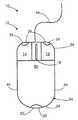
本発明の1つの好ましい実施形態による動作モード表示装置10を図1に示し、本明細書では、マウスタイプのコンピュータ・ポインティングデバイス(マウス)12の動作モードを示すために使用することができるものとして説明する。例えば、動作モード表示装置10は、ユーザに対し、マウス12がスタンバイモード(例えば、ユーザが使用していない状態)であること、或いはアクティブモード又は入力モード(例えば、ユーザが使用している状態)であることを示してよい。動作モード表示装置10は、更に、マウス12の動作モードに関するより具体的な情報を提供することができてよい。例えば、動作モード表示装置10は、ユーザの手がマウス12と接触しているか或いはマウス12に極めて近接している時(マウス12へのアクセス時),マウス12が移動している時,及び/又はマウスボタン(例えば、第1又は第2のマウスボタン14又は16、スクロールホイール18)が押下された時に表示するように構成されてよい。
【0011】
ここで最初に、図1を参照すると、1つの好ましい実施形態で利用される動作モード表示装置10は、第1の照明装置(illumination apparatus)又は点灯装置(lighting device)20を備えてよい。第1の点灯装置20は、マウス12が第1の動作モード又は状態である時に光を生成してよい。本明細書で示して説明する実施形態では、第1の点灯装置20は、マウス12が移動されていない時に点灯する。第1の点灯装置20は、マウス12の後部24に隣接して配置される赤色発光ダイオード(「LED」)22を備えることが概して好ましいが、これは必ずしも必要ではなく、他の光源,他の色,及び他の配置も可能である。
【0012】
動作モード表示装置10は、更に、マウス12が第2の動作モード又は状態である時に光を生成する第2の照明装置又は点灯装置26を有してよい。本明細書で示して説明する実施形態では、第2の点灯装置26は、カーソル28をコンピュータ表示画面30(図2参照)上で移動させるためにマウス12が移動されている時に、点灯する。第2の点灯装置26は、マウス12の前部36に隣接して配置される一対の緑色LED32,34を備えることが概して好ましいが(図1参照)、これらは必ずしも必要ではなく、他の光源,他の色,及び他の配置も可能である。
【0013】
動作モード表示装置10の機能を実行するために、動作的にマウス12と関連するデータ処理システム52(図3参照)が提供されてよい。データ処理システム52は、マウス12からマウス12の動作モードを示すデータ信号54を受信することができる。すなわち、データ信号54は、例えば、マウス12が移動している時及び/又はマウスボタン(例えば、第1又は第2のマウスボタン14又は16、スクロールホイール18)が起動された時に関する情報を提供してよい。データ処理システム52は、マウス12からデータ信号54を受信すると、アルゴリズム56に従ってデータ信号54を処理することができる。
【0014】
制御システム58は、データ処理システム52からの処理済みデータ信号59を受信することができる。それに応じて、制御システム58は、動作モード表示装置10の適当な点灯装置20又は26を作動(すなわち、点灯又は消灯)させてよい。
【0015】
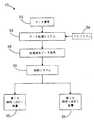
動作モード表示装置10は、図4に示す方法60に従って動作させることができる。方法60の第1のステップ62では、マウス12の移動があるか否かについて判断が行われる。ステップ62においてマウス12が移動していると判断された場合には、ステップ64において、点灯装置26の緑色LED32,4が点灯される。一方、ステップ62において、マウス12が移動していないと判断された場合には、ステップ66において、点灯装置20の赤色LED22が点灯される。
【0016】
方法60が実行される前に点灯装置20又は26の何れかが点灯されていた場合、マウス12の動作モードが変化すると、その点灯装置は消灯される必要のある場合がある。従って、ステップ64は、更に、第1の点灯装置20の赤色LED22を消灯することを含んでよい。また、ステップ66は、更に、第2の点灯装置26の緑色LED32,34を消灯することを含んでよい。従って、ユーザは、マウス12が第1の動作モードである時は第1の点灯装置20のみが点灯され、マウス12が第2の動作モードである時は第2の点灯装置26が点灯されるのを見ることになる。
【0017】
本発明の重要な利点は、点灯装置20又は26の何れかが点灯されている場合に、ユーザがそれらの何れが点灯されているかを見る(視認する)ことによってマウス12の動作モードを確定する(見分ける)ことができるため、使用が容易である、という点にある。また、動作モード表示装置10により、ユーザは、マウス12が配置される作業面が、マウス12が移動する時に回転可能ボールが移動するように十分な牽引摩擦を提供するか否かを、迅速に判断することができる。後により詳細に説明するように、緑色LED32,34は、マウス12の内部のトランスデューサが回転可能ボールの移動を検知した時に、点灯する。このため、緑色LED32,34が、マウス12が作業面上で移動する時に点灯しない場合には、作業面は、マウス12の適当な使用のために十分な摩擦を提供していない可能性がある。これとは別に、マウス12が光学式マウスである場合、マウス12が作業面上で移動する時に緑色LED32,34が点灯しないことは、マウス12の適当な使用のためには作業面の反射性が高過ぎるということを示す可能性がある。
【0018】
本発明の他の重要な利点は、動作モード表示装置10が備えられているマウス12又は他のコンピュータ・ポインティングデバイスの取付け以外には、コンピュータシステム自体に対する如何なるハードウェアの変更も必要ではない、ということである。また、動作モード表示装置10は、トラックボール等の他の様々なコンピュータ・ポインティングデバイスのうちの如何なるものとも使用される融通性を有する。最後に、動作モード表示装置10は、マウス12が配置される作業面のための照明を提供し、また、マウス12に対し美的品質も提供する。
【0019】
本発明の一実施形態による動作モード表示装置10について、そのより重要な特徴及び利点のうちのいくつかと共に簡単に説明したが、ここで、動作モード表示装置10を詳細に説明する。しかしながら、説明を続ける前に、本明細書では動作モード表示装置10をマウス12と共に使用することができるように示して説明するが、トラックボール,トラックパッド,グラフィックスタブレット,ジョイスティック,ライトペン,パック等の他の様々なコンピュータ・ポインティングデバイスのうちの如何なるものと共に使用することができる、ということが留意されなければならない。従って、本発明は、本明細書で示して説明する特定のマウス12と共に使用することに限定されるものとみなされるべきではない。
【0020】
上述したことを留意しながら、本明細書では、動作モード表示装置10の一実施形態を、コンピュータシステム72(図2参照)及びそれに接続されたマウス12と共に使用することができるものとして示して説明する。コンピュータシステム72は、当該技術分野において現在既知であるか又は将来開発される可能性のある広範囲のコンピュータシステムのうちの何れを備えてもよい。例えば、マウス12が使用されてよいコンピュータシステム72は、モニタ30,プリンタ74,処理装置76,及びキーボード78を有してよいが、他の構成も可能である。
【0021】
図1に戻ると、コンピュータシステム72と共に使用されることが可能なマウス12には、ユーザが片手で把持又は握持するようなサイズであるハウジング又はケーシング94が設けられてよい。ハウジング94は、上面50と、底面(図示せず)と、互いに対向する側部44,46とを有してよい。
【0022】
また、マウス12は、光センサ,マウス12の基部に取付けられた回転可能ボール、又はそれらの組合せ等の多方向検出装置(図示せず)を有してもよい。マウス12に回転可能ボールが設けられる場合には、回転可能ボールの一部は、デスクトップ又はマウスパッド等の作業面に摩擦係合することができるようにハウジング94の下面から外側に延在し、マウス12が作業面に対して移動する時に回転する。
【0023】
マウス12は、ボールの移動を検知しその移動の方向及び量を示す信号を生成するトランスデューサ(図示せず)を更に有してよい。すなわち、トランスデューサは、マウス12の並進移動を位置信号に変換する。信号は、最終的にコンピュータシステム72に送信され、作業面に対するマウス12の相対移動を反映するように表示画面30上でカーソル28を移動させるために使用される。
【0024】
また、マウス12には、押下された時に関連するスイッチの状態を変更し、それにより種々のコマンドのコンピュータシステム72への入力を可能にするマウスボタン14,16が設けられてもよい。入力されるコマンドの性質は、通常、表示画面30上のカーソル28の位置によって決まる。言い換えれば、ユーザは、まずマウス12を使用してカーソル28を所望の項目又はコマンド上に配置し、その後に適当なマウスボタン14又は16を押下することにより「マウスクリック」として知られるものをもたらすことによって、コンピュータ画面30上に表示される項目又はコマンドを選択することができる。本明細書で示して説明する実施形態では、マウスボタン14,16は、ハウジング94の前部36に隣接する上面50に配置されるが、それは必ずしもそうである必要はない。
【0025】
また、マウス12には、スクロールホイール18が設けられてもよい。本明細書で示して説明する実施形態では、スクロールホイール18は、第1のマウスボタン14と第2のマウスボタン16との間においてハウジング94の上面50から上方に突出するように、ハウジング94内に配置される軸(図示せず)に取付けられる。スクロールホイール18の取付構成により、ユーザは、スクロールホイール18を回転させ及び/又は押下することができる。スクロールホイール18は、スクロールホイール18の回転及び/又は押下を示す信号を生成するトランスデューサ(図示せず)に連結されてよい。信号は、コンピュータ表示画面30上に表示されるウインドウを通して、スクロール等の表示画面30上の変化をもたらすために使用されてよい。
【0026】
説明を続ける前に、マウス12についての上記の説明は例示の目的のみのためであるということに留意されなければならない。すなわち、マウス12には、マウス12の都合のよい如何なる位置にも配置される都合のよい如何なる数の起動キー又はボタンが設けられてもよい。従って、本発明は、本明細書で示して説明する特定のマウス12及びその配置に限定されるべきではない。
【0027】
ここで説明を続けると、マウス12は、相互接続ケーブル96を介してコンピュータシステム72に接続されてよい。相互接続ケーブル96により、マウス12及びコンピュータシステム72は、互いに通信することができる。言い換えれば、マウス12とコンピュータシステム72とは、相互接続ケーブル96を通して互いに信号を送受信することができる。相互接続ケーブル96は、マウス12に専用のコンピュータシステム72のマウスポート(図示せず)に差し込まれてよい。マウスポートが使用可能でない場合には、相互接続ケーブル96は、代わりにユニバーサルシリアルバス(USB)ポート(図示せず)に差込まれてよい。これとは別に、マウス12は、PS/2ポート(図示せず)等の特別なカード又は他のポートを通してコンピュータのバス(同様に図示せず)に取付けられてよい。他の代替実施形態では、マウス12は無線であってよい。すなわち、マウス12とコンピュータシステム72との間の通信は、相互接続ワイヤ又はケーブルを必要とすることなく、無線や赤外線等によって行われてよい。
【0028】
また、相互接続ケーブル96は、マウス12に電力を供給するためにも使用されてよい。これとは別に、マウス12には、内部電源(例えば、電池)が設けられてもよい。
【0029】
マウス12に対する特定の配置に拘わらず、一実施形態による動作モード表示装置10は、第1の照明装置又は点灯装置20を有してよい。第1の点灯装置20は、マウス12が第1の動作モード又は状態である時に光を生成してよい。本明細書で示して説明する実施形態では、第1の点灯装置20は、ユーザがマウス12を移動していないか、又はより詳細には、マウス12の回転可能ボール又は他のカーソル移動制御装置を移動していない時に、点灯する。これとは別に、第1の動作モードは、当業者が本発明の教示を熟知した後に明らかとなるように、マウス12に対する他の様々な動作モードのうちの如何なるものを含んでもよい。例えば、マウス12のスクロールホイール18を使用不能にすることが、マウス12の第1の動作モードに含まれてよい。
【0030】
第1の点灯装置20がLED22を備えるということは、概して好ましいが、必ずしも必要ではない。これとは別に、第1の点灯装置20は、当業者が本発明の教示を熟知した後に明らかとなるように、他の様々な光源のうちの如何なるものを備えてもよい。
【0031】
また、少なくとも1つの属性(例えば、色,強度,点滅速度,色合い,彩度,輝度等)が第2の点灯装置26によって生成される光とは異なる光を第1の点灯装置20から生成させることも好ましいが、必ずしもそうである必要はない。例えば、本明細書で示して説明する実施形態では、第1の点灯装置20は、赤色光を生成する赤色LED22を備え、第2の点灯装置26は、緑色光を生成する。これに代えて、第1の点灯装置20は、ユーザが赤色光として見えるように、赤色フィルタを通して伝わる広帯域光を生成することができる。
【0032】
第1の点灯装置20は、生成する光がユーザに見えるように、ハウジング94の後部24に直接取付けられてよい。これとは別に、第1の点灯装置20がハウジング94内に取付けられ、ハウジング94によって画定される開口(図示せず)に隣接して配置されることにより、第1の点灯装置20の生成する光が開口を通過してユーザが見ることができるようにしてもよい。また、当業者が本発明の教示を熟知した後に明らかとなるように、更に他の取付構成が可能である。
【0033】
動作モード表示装置10は、更に、マウス12が第2の動作モード又は状態である時に光を生成する第2の照明装置又は点灯装置26を有してよい。本明細書に示して説明する実施形態では、第2の点灯装置26は、マウス12が移動している時、又はより詳細には、マウス12内のトランスデューサが回転可能ボールか又は他のカーソル移動制御装置の移動を検出する時に、点灯する。これとは別に、第2の動作モードは、当業者が本発明の教示を熟知した後に明らかとなるように、マウス12に対する他の様々な動作モードのうちの如何なるものを含んでもよい。例えば、第2の点灯装置26は、マウスクリックがもたらされる度に光を生成してよい。
【0034】
第2の点灯装置26は、一対のLED32及び34を備えることが概して好ましいが、必ずしも必要ではない。代替的に、第2の点灯装置26は、当業者に対して本発明の教示を熟知した後に明らかとなるように、他の様々な光源のうちの如何なるものを備えてもよい。
【0035】
また、少なくとも1つの属性(例えば、色,強度,点滅速度,色合い,輝度等)が第1の点灯装置20が生成する光とは異なる光を第2の点灯装置26から生成させることも好ましいが、それは必ずしも必要ではない。例えば、本明細書で示して説明する実施形態では、第2の点灯装置26は、緑色光を生成する緑色LED32,34を備え、第1の点灯装置20は、赤色光を生成する。これとは別に、第2の点灯装置26は、ユーザが緑色光として見えるように、緑色フィルタを通して伝わる広帯域光を生成することができる。
【0036】
第2の点灯装置26のLED32,34は、生成する光がユーザに見えるように、ハウジング94の前部36に直接取付けられてよい。これとは別に、第2の点灯装置26のLED32,34がハウジング94内に取付けられ、ハウジング94によって画定される一対の開口(図示せず)に隣接して配置されることにより、LED32,34の生成する光が開口を通過しユーザが見ることができるようにしてもよい。しかしながら、当業者が本発明の教示を熟知した後に明らかとなるように、他の取付構成も可能である。
【0037】
動作モード表示装置10の機能を実行するために、データ処理システム52(図3参照)が提供されてよい。より詳細には、後により詳細に説明するように、データ処理システム52は、まず、マウス12の動作モード又は状況(状態)を示すデータ信号54をマウス12から受信することにより、動作モード表示装置10の機能を実行する。例えば、データ信号54は、マウス12が移動している時、又はより詳細には、マウス12内のトランスデューサがマウス12の回転可能ボールか又は他のカーソル移動制御装置の移動を検出する時に関する情報を提供してよい。マウス12が第1の動作モードである(すなわち、移動してない)場合には、データ処理システム52は、マウス12の非移動状態を示すデータ信号54を受信してよい。データ処理システム52は、マウス12からデータ信号54を受信すると、アルゴリズム56に従ってデータ信号54を処理することができる。
【0038】
動作モード表示装置10のためのデータ処理機能は、マウス12自体の内部で生じることが概して好ましいが、これは必ずしも必要ではない。すなわち、データ処理システム52は、マウス12のハウジング94内に組込まれるか常駐してよい。これとは別に、データ処理機能は、コンピュータシステム72のプロセッサ76内で施行してよい。言い換えれば、種々のデータ処理機能を実行するコンピュータ読取可能プログラムコードが提供されてよい。かかるプログラムコードは、コンピュータ読取可能記憶装置体内に格納されプロセッサ76上で作動させることができる。他の代替実施形態では、マウス12と動作モード表示装置10とに動作的に関連する特別に設計された(例えば「ハードワイヤード」)装置(図示せず)が提供されてよい。この特別に設計された装置は、マウス12によって生成されるデータ信号54を処理することができる。更に他の代替実施形態では、データ処理機能は、マウス12とコンピュータシステム72のCPU76との間で分配され、各々が処理機能の一部を実行してよい。何れの場合も、データ処理システム52のための適当な構成は、特定の用途に対する要件を考慮した後及び本発明の教示を熟知した当業者により容易に見出され得る。
【0039】
データ処理システム52は、当該技術分野において既知である様々なデータ処理システムのうちの何れを備えてもよい。従って、本発明は、如何なる特定のタイプのデータ処理システムにも限定されるものとみなされるべきではない。更に、データ処理システムは当該技術分野において既知であり、データ処理システム自体の詳細は本発明を理解するために必要ではないため、本発明の1つの好ましい実施形態において利用される特定のデータ処理システムについて、本明細書ではこれ以上詳細には説明しない。
【0040】
利用されるデータ処理システムのタイプに拘わらず、マウス12のハウジング94の外部にデータ処理システム52の何れかの部分が存在する場合、データがマウス12からデータ処理システム52に転送又は「ダウンロード」されることを可能にするために、データ処理システム52に1つ又は複数の通信ポート(図示せず)を設けることが一般的には望ましい。様々な既知の通信ポート及びフォーマットのうちの如何なるものが利用されてもよいが、1つの好ましい実施形態では、データ処理システム52には、ユニバーサルシリアルバス(USB)ポート(図示せず),赤外線(IR)シリアルポート(同様に図示せず),及び/又はBLUETOOTHTM(商標)設けられてよい。
【0041】
このように、データ処理システム52は、アルゴリズム56に従ってデータ信号54を処理することができる。アルゴリズム56は、マウス12内、例えば上記のデータ処理システム52内に格納されてよい。これとは別に、アルゴリズム56は、コンピュータシステム72のコンピュータ読取可能記憶装置に格納されるコンピュータ読取可能プログラムコードを有してよい。
【0042】
ここで、データ処理システム52によりデータ信号54が処理されたとすると、処理済みデータ信号59は、制御システム58によって受信されてよい。それに応じて、制御システム58は、動作モード表示装置10の適当な点灯装置20又は26を作動して(すなわち、点灯又は消灯して)よい。
【0043】
また、動作モード表示装置10には、電源が設けられてもよい。動作モード表示装置10に、コンピュータシステム72の動作状況に依存しない電源が設けられることが概して好ましいが、これは必ずしも必要ではない。例えば、1つの好ましい実施形態では、マウス12と動作モード表示装置10との両方に対し、マウス12のハウジング94内に配置される電池(図示せず)によって電力が供給される。これとは別に、動作モード表示装置10は、コンピュータシステム72に電力を供給する同じ電源から(例えば、相互接続ケーブル96を通して)その電力を受取ってよい。
【0044】
動作モード表示装置10用の電源がコンピュータシステム72の動作状況に依存しない場合、コンピュータシステム72がシャットダウンされた後の長期間にわたり動作モード表示装置10が動作可能状態のままでないように、時間遅延シャットオフスイッチ(図示せず)が設けられることが一般的に好ましい。時間遅延シャットオフを提供することにより、動作モード表示装置10は、ある非活動期間後に如何なるユーザ介入もない場合にシャットオフされてよい。すなわち、マウス12が所定期間使用されなかった場合及び/又はコンピュータシステム72が所定期間動作不能であった場合には、シャットオフされてよい。
【0045】
また、動作モード表示装置10は、ユーザが動作モード表示装置10を使用不能にするか又はシャットオフにすることができるスイッチ98を有してもよい。例えば、ユーザは、スイッチ98を介して動作モード表示装置10をシャットオフすることにより、電力を節約するか又は動作モード表示装置10を作動状態とすることなく単にマウス12を使用することができる。
【0046】
動作モード表示装置10をシャットオフする理由に拘わらず、スイッチ98は、コンピュータ表示画面30上に表示されるユーザ選択可能インタフェース100(例えば、アイコン又はダイアログボックス)(図5参照)として実現されてよい。このユーザ選択可能インタフェース100により、ユーザは、単に、マウス12又は他のコンピュータ・ポインティングデバイスを用いてコンピュータ表示画面30上の適当なボックスをマークすることにより、動作モード表示装置10に対する「ON」設定と「OFF」設定とを選択することができる。例えば、図5は、ユーザが動作モード表示装置10のために「ON」設定を選択したことを示している。
【0047】
コンピュータシステム72は、当該技術分野において現在既知であるか又は将来開発される可能性のある、コンピュータシステム72がユーザ選択可能インタフェース100を表示することができるようにする様々なプログラミング方法のうちの如何なるものに従ってプログラムされてもよい。すなわち、ユーザは、本発明の教示を熟知した後に、ユーザ選択可能インタフェース100を表示するようにコンピュータシステム72を容易にプログラムすることができる。従って、ユーザ選択可能インタフェース100を表示するためにコンピュータシステム72をプログラムすることに関連する詳細については、本明細書においてこれ以上説明しない。
【0048】
代替実施形態では、スイッチ98は、マウス12のハウジング94に取付けられるスイッチ(図示せず)を含んでよい。かかる実施形態では、スイッチは、「ON」と「OFF」との設定の間で移動可能であるようにハウジング94に取付けられてよい。
【0049】
上述したように、動作モード表示装置10は、図4に示す方法60に従って作動されてよい。方法60の第1ステップ62では、マウス12の移動があるか否かが判断される。ステップ62において、マウス12が移動していると判断された場合には、ステップ64において、点灯装置26の緑色LED32,34が点灯される。一方、ステップ62において、マウス12が移動していないと判断された場合には、ステップ66において、点灯装置26の赤色LED22が点灯される。
【0050】
また、本発明では、図4に示すものより多くのステップを含む方法も考えられる。例えば、方法60が実行される前に点灯装置20又は26の何れかが点灯されていた場合には、マウス12の動作モードが変化するとその点灯装置は消灯される必要のある場合がある。従って、ステップ64は、更に、第1の点灯装置20の赤色LED22を消灯することを含んでよい。ステップ66は、更に、第2の点灯装置26の緑色LED32,34を消灯することを含んでよい。従って、ユーザは、マウス12が第1の動作モードである時は第1の点灯装置20のみが点灯され、マウス12が第2の動作モードである時は第2の点灯装置26のみが点灯されるのを見ることになる。
【0051】
単に例として、第1の点灯装置20がマウス12の第1の動作モードを示すように光を生成しているとする。マウス12が第1の動作モードから第2の動作モードに変更されると、第2の点灯装置26の緑色LED32,34が点灯されるのと略同時に、第1の点灯装置20の赤色LED22が消灯されてよく、それによってユーザが、マウス12が第2の動作モードである時に緑色LED32,34のみが点灯されるのを見ることとなる。
【0052】
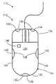
動作モード表示装置10の第2の実施形態110を図6に示す。それは、第1の照明装置又は点灯装置120を有してよい。第1の点灯装置120は、マウス112が第1の動作モード又は状態である時に光を生成してよい。すなわち、本明細書で示して説明する実施形態では、第1の点灯装置120は、ユーザがマウス112に触れていない時に点灯する。第1の点灯装置120は、マウス112の後部124に隣接して配置される赤色発光ダイオード(「LED」)122を備えることが概して好ましいが、これは必ずしも必要ではなく、他の光源,他の色,及び他の配置が可能である。
【0053】
動作モード表示装置110は、更に、マウス112が第2の動作モード又は状態である時に光を生成する第2の照明装置又は点灯装置126を有してよい。本明細書で示して説明する実施形態では、第2の点灯装置126は、マウス112が移動している時に点灯する。より詳細には、第2の点灯装置126は、マウス112内のトランスデューサがマウス112のカーソル移動制御装置の移動を検出した時に光を生成する。第2の点灯装置126は、マウス112の前部136に隣接して配置される一対の緑色LED132,134を備えることが概して好ましいが、これは必ずしも必要ではなく、他の光源、他の色,及び他の配置が可能である。
【0054】
また、動作モード表示装置110には、マウス112が第3の動作状態又はモードである時に点灯する第3の照明装置又は点灯装置138が設けられてもよい。本明細書で示して説明する実施形態では、第3の点灯装置138は、ユーザの手がマウス112と接触しているがマウス112が移動していない時か、又はより詳細には、マウス112の回転可能ボール又は他のカーソル移動制御装置が移動していない時に、光を生成する。第3の点灯装置138は、マウス112の互いに対向する側部144,146にそれぞれ配置される一対の黄色LED140及び142を備えることが概して好ましいが、これは必ずしも必要ではなく、他の光源、他の色,及び他の配置が可能である。
【0055】
ユーザの手がマウス112に接触している時を確定(判定)するために、ユーザ検出装置148が設けられてよい。ユーザ検出装置148は、動作モード表示装置110が、ユーザの手がマウス112に接触している時を確定することができるようにする。より詳細には、ユーザ検出装置148は、データ処理システム52に対し、マウス112の動作モード又は状況を示すデータ信号54を送信してよい。
【0056】
本明細書に示して説明する実施形態では、ユーザ検出装置148は、ハウジング194の上面150に配置されており、そして本装置148は光センサを備えている。これとは別に、ユーザ検出装置148は、ユーザの手によって生成される熱を検出する熱センサを備えてよい。他の代替実施形態では、ユーザ検出装置148は、ユーザの手がハウジング194上に配置されるとマウス112に印加される圧力がそのスイッチを駆動するようにマウス112の上に配置された、圧力駆動スイッチのような、機械的に駆動されるスイッチを備えてよい。更に他の代替実施形態では、ユーザ検出装置148は、当該技術分野において既知であり容易に購入可能なタイプの静電容量型近接センサを備えてよい。
【0057】
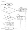
動作モード表示装置110は、図7に示す方法160に従って作動されてよい。方法160の第1のステップ162では、ユーザの手がマウス112に接触しているか否かが判断される。ステップ162において、ユーザの手がマウス112に接触していないと判断された場合には、ステップ164において、第1の照明装置120の赤色LED122が点灯される。一方、ステップ162において、ユーザの手がマウス112に接触していると判断された場合には、ステップ166において、マウス112が移動しているか否かが更に判断される。ステップ166において、マウス112が移動していると判断された場合には、ステップ168において、第2の照明装置126の緑色LED132,134が点灯される。一方、ステップ166において、マウス112が移動していないと判断された場合には、ステップ170において、第3の照明装置138の黄色LED140,142が点灯される。
【0058】
方法60(図4)について上述したように、方法160を実行する前に動作モード表示装置110の点灯装置120,126,138が点灯されていた場合には、マウス112が動作モードを変更するとその点灯装置は消灯される必要のある場合がある。従って、ステップ164は、更に、点灯装置126の緑色LED132,134を消灯することと、点灯装置138の黄色LED140,142を消灯することとを含んでよい。ステップ168は、更に、点灯装置120の赤色LED122を消灯すること、及び/又は、点灯装置138の黄色LED140,142を消灯することを含んでよい。また、ステップ170は、点灯装置126の緑色LED132,134を消灯すること、及び/又は、点灯装置120の赤色LED122を消灯することを含んでよい。従って、ユーザは、マウス112が第1の動作モードである時は第1の点灯装置120のみが点灯され、マウス112が第2の動作モードである時は第2の点灯装置126のみが点灯され、マウス112が第3の動作モードである時は第3の点灯装置138のみが点灯されるのを見ることになる。
【0059】
図示されていない代替実施形態では、動作モード表示装置は、マウスに対する種々の動作モードを示すために使用される単一の照明装置又は点灯装置(図示せず)を含んでよい。より詳細には、単一の点灯装置は、所定の動作モードを表示するために、少なくとも1つの属性(例えば、色,強度,点滅速度,色合い,彩度,輝度等)がマウスの他の動作モードに対して生成する光とは異なる光を生成してよい。例えば、単一の点灯装置は、マウスの第1の動作モードに対して点滅光を生成してよく、またマウスの第2の動作モードに対して点灯光を常時生成してもよい。
【0060】
また、動作モード表示装置10t同等の機能性を有することも可能である。すなわち、マウス12の他の様々な動作モードのうちの如何なるものを示すようにも、動作モード装置をプログラムすることができ、及び/又は動作モード装置に追加の点灯装置を設けることができる。例えば、第1及び第2の点灯装置20及び26を組合せて使用することにより、マウス12の第4の動作モードを示すことができ、緑色LED32が、第1のマウスボタン14が押下された時に点灯してよく、及び/又は緑色LED34が、第2のマウスボタン16が押下された時に点灯してよい。
【0061】
更に、コンピュータ・ポインティングデバイスの動作モード又は設定を変更することをユーザが必要とするか又はそれがユーザにとって望ましい場合があるため、動作モード表示装置を、ユーザがかかる変更を行うのを支援するために使用することができる。例えば、ユーザは、マウス12を使用してビデオゲームを行う前に、マウス12のスクロールホイール18を使用不能にすることが必要である場合がある。スクロールホイール18を使用不能にするために、ユーザは、まず、コンピュータプログラムにアクセスしなければならない場合がある。しかしながら、コンピュータプログラムを使用している間において、ユーザは、後にマウス12を使用するまでスクロールホイール18が実際に使用不能とされたか否かを知ることができない可能性がある。ユーザは、スクロールホイール18が適切に使用不能とされなかったことに気づくと、再びコンピュータアプリケーションにアクセスし、スクロールホイール18を使用不能にすることを再度試みるという、時宜を得たプロセスを経ることが必要である場合がある。しかし、スクロールホイール18が使用不能である時に点灯する点灯装置を有する動作モード表示装置をマウス12に設けた場合、この時間のかかるプロセスを避けることができる。言い換えれば、ユーザは、動作モード表示装置を構成する何れかの照明装置が光を生成している場合には、その何れが光を生成しているかを見ることにより、スクロールホイール18が使用不能とされたか否かを迅速に判断することができる。代替的に、動作モード表示装置は、また、当業者が本発明の教示を熟知した後に明らかとなるように、マウス12に対する他の様々な設定又は動作モードのうちの如何なるものを示すために使用することも可能である。
【0062】
本明細書で説明したコンピュータ読取可能プログラムコードを、当該技術分野において現在既知であるか又は将来開発される可能性のある様々の適当なコンピュータ読取可能プログラミング言語の如何なるものを使用しても従来通りにプログラムすることが可能である、ということが理解されなければならない。また、コンピュータ読取可能プログラムコードが、1つ又は複数の機能,ルーチン,サブ機能,及びサブルーチンを含むことができ、単一のソフトウェアパッケージに結合される必要はない、ということも理解されなければならない。
【0063】
以上を要約すると、次の通りである。すなわち、コンピュータ・ポインティングデバイス(12,112)のための動作モード表示装置(10,110)は、第1の照明(点灯)装置(20,120)及び第2の照明(点灯)装置(26,126)を含んでいてよい。第1の照明装置(20,120)は、コンピュータ・ポインティングデバイス(12,112)と動作的に関連されており、コンピュータ・ポインティングデバイス(12,112)が第1の動作モードである時に光を生成(発生)する。また、第2の照明装置(26,126)は、コンピュータ・ポインティングデバイス(12,112)と動作的に関連されており、コンピュータ・ポインティングデバイス(12,112)が第2の動作モードである時に光を生成する。
【0064】
本明細書で説明した発明の概念は、他の方法で種々に具体化されてよいということが考えられ、併記の特許請求の範囲は、従来技術によって限定されることを除き、本発明の代替実施形態を含むように解釈されることが意図されている。
【図面の簡単な説明】
【図1】マウスタイプのコンピュータ・ポインティングデバイスと共に使用することができる本発明の1つの好ましい実施形態による動作モード表示装置の平面図である。
【図2】図1に示すマウスが使用され得るコンピュータシステムの一実施形態を示すシステム図である。
【図3】図1に示す動作モード表示装置の構成要素を示すブロック図である。
【図4】図1に示すマウスの動作モードを表示するための方法を示すフローチャートである。
【図5】図1に示す動作モード表示装置を使用してコンピュータユーザに提供され得る画面表示を示す平面図である。
【図6】マウスタイプのコンピュータ・ポインティングデバイスと共に使用することができる本発明の代替実施形態による動作モード表示装置を示す平面図である。
【図7】図6に示すマウスの動作モードを表示するための方法を示すフローチャートである。
【符号の説明】
10,110 動作モード表示装置
12,112 コンピュータ・ポインティングデバイス(マウス)
14 第1のマウスボタン
16 第2のマウスボタン
18 スクロールホイール
20,120 第1の照明(点灯)装置
22,122 赤色LED
32,34,132,134 緑色LED
26,126 第2の照明(点灯)装置
28 カーソル
30 コンピュータ表示画面
72 コンピュータシステム
138 第3の照明(点灯)装置
140,142 黄色LED[0001]
BACKGROUND OF THE INVENTION
The present inventionComputer pointing device (eg mouse) and method for displaying the operating mode of a computer pointing device About.
[0002]
[Prior art]
There are many different types of computer pointing devices that are used to enter commands into a computer. Such a computer pointing device, in particular, for performing operations such as “pressing” an on-screen button in a dialog box, selecting a menu item, and selecting a range of cells or a group of documents in a spreadsheet. Can be used to control an on-screen cursor (ie, an arrow or other on-screen icon that moves with the corresponding movement of the computer pointing device).
[0003]
A typical computer pointing device is provided with a cursor movement control device that allows a user to move a cursor on a computer display screen. For example, a mouse cursor movement control device may include a rotatable ball and a movement detection device or transducer. More recently, however, optical sensors have been used as cursor movement control devices for mice.
[0004]
When a rotatable ball configuration is used, the motion detector or transducer senses the movement of the ball and generates a signal indicating the direction and amount of movement. The signal is finally sent to the computer and converted into cursor movement on the computer display screen.
[0005]
The computer pointing device may further include one or more buttons that change the state of the associated switch when pressed, thereby allowing various commands to be entered into the computer. The nature of the command entered is usually determined by the position of the cursor on the screen. In other words, the user first selects an item or command displayed on the computer screen by placing the cursor on the desired item or command and then pressing the appropriate button on the computer pointing device. Can do.
[0006]
In order to allow a computer pointing device to communicate with a computer and vice versa, the computer pointing device may be connected to the computer by an interconnection cable or wire. Alternatively, the computer pointing device may be wireless. For example, communication between a computer pointing device and a computer may be performed wirelessly or by infrared, without using any interconnection wires or cables.
[0007]
[Problems to be solved by the invention]
A main object of the present invention is to make it possible to determine (recognize) an operation mode of a computer pointing device (for example, a mouse) by visual recognition.
[0008]
[Means for Solving the Problems]
An operation mode display device for a computer pointing device may comprise a first lighting device and a second lighting device. The first lighting device is operatively associated with the computer pointing device and generates light when the computer pointing device is in the first mode of operation. The second lighting device is operatively associated with the computer pointing device and generates light when the computer pointing device is in the second mode of operation.
[0009]
A step of providing a first lighting device and a second lighting device to the computer pointing device; a step of determining whether the computer pointing device is in a first operation mode; and a computer pointing device. Turning on the first lighting device when it is determined that is in the first operation mode, determining whether the computer pointing device is in the second operation mode, and a computer pointing device Illuminating the second lighting device when it is determined to be in the second mode of operation, and a method for indicating the mode of operation of the computer pointing device is also disclosed.
[0010]
DETAILED DESCRIPTION OF THE INVENTION
Exemplary and presently preferred embodiments of the invention are illustrated in the accompanying drawings.
An
[0011]
Referring first to FIG. 1, the operating
[0012]
The operation
[0013]
A data processing system 52 (see FIG. 3) operatively associated with the
[0014]
The
[0015]
The operation
[0016]
If either
[0017]
An important advantage of the present invention is that when one of the
[0018]
Another important advantage of the present invention is that no hardware changes to the computer system itself are required other than the attachment of a
[0019]
Having briefly described the operation
[0020]
With the foregoing in mind, an embodiment of the
[0021]
Returning to FIG. 1, the
[0022]
In addition, the
[0023]
The
[0024]
The
[0025]
Further, the
[0026]
Before continuing the description, it should be noted that the above description of
[0027]
Continuing with the description,
[0028]
The
[0029]
Regardless of the specific arrangement with respect to the
[0030]
Although it is generally preferred that the
[0031]
In addition, the
[0032]
The
[0033]
The operation
[0034]
Although it is generally preferred that the
[0035]
In addition, it is preferable to generate light from the
[0036]
The
[0037]
In order to perform the functions of the operation
[0038]
Although it is generally preferred that the data processing functions for the operating
[0039]
[0040]
Regardless of the type of data processing system utilized, if any portion of the
[0041]
Thus, the
[0042]
Here, if the data signal 54 has been processed by the
[0043]
The operation
[0044]
If the power supply for the operation
[0045]
The operation
[0046]
Regardless of the reason for shutting off the operating
[0047]
The
[0048]
In an alternative embodiment, the
[0049]
As described above, the operation
[0050]
The present invention also contemplates a method that includes more steps than those shown in FIG. For example, if either of the
[0051]
By way of example only, assume that the
[0052]
A
[0053]
The operation
[0054]
Further, the operation
[0055]
A
[0056]
In the embodiment shown and described herein, the
[0057]
The
[0058]
As described above with respect to the method 60 (FIG. 4), if the
[0059]
In an alternative embodiment not shown, the operational mode display may include a single lighting device or lighting device (not shown) that is used to indicate various operational modes for the mouse. More specifically, a single lighting device has at least one attribute (eg, color, intensity, blink rate, tint, saturation, brightness, etc.) other operations of the mouse to display a given mode of operation. Light that is different from the light generated for the mode may be generated. For example, a single lighting device may generate blinking light for the first operating mode of the mouse and may always generate lighting light for the second operating mode of the mouse.
[0060]
Moreover, it is also possible to have functionality equivalent to the operation mode display device 10t. That is, the operation mode device can be programmed to indicate any of the other various operation modes of the
[0061]
In addition, since the user may or may need to change the operating mode or setting of the computer pointing device, the operating mode display device can assist the user in making such changes. Can be used for For example, the user may need to disable the
[0062]
The computer readable program code described herein may be used conventionally using any of a variety of suitable computer readable programming languages currently known in the art or that may be developed in the future. It must be understood that it is possible to program in It should also be understood that the computer readable program code can include one or more functions, routines, sub-functions, and subroutines and need not be combined into a single software package. .
[0063]
The above is summarized as follows. That is, the operation mode display device (10, 110) for the computer pointing device (12, 112) includes the first lighting (lighting) device (20, 120) and the second lighting (lighting) device (26, 126). The first lighting device (20, 120) is operatively associated with the computer pointing device (12, 112) and emits light when the computer pointing device (12, 112) is in the first mode of operation. Generate (generate). The second lighting device (26, 126) is also operatively associated with the computer pointing device (12, 112) when the computer pointing device (12, 112) is in the second mode of operation. Produce light.
[0064]
It is contemplated that the inventive concepts described herein may be variously embodied in other ways, and the scope of the appended claims is an alternative to the present invention except that it is limited by the prior art It is intended to be construed to include embodiments.
[Brief description of the drawings]
FIG. 1 is a plan view of an operating mode display device according to one preferred embodiment of the present invention that can be used with a mouse-type computer pointing device.
FIG. 2 is a system diagram illustrating one embodiment of a computer system in which the mouse illustrated in FIG. 1 may be used.
FIG. 3 is a block diagram showing components of the operation mode display device shown in FIG. 1;
FIG. 4 is a flowchart illustrating a method for displaying an operation mode of the mouse illustrated in FIG. 1;
5 is a plan view showing a screen display that can be provided to a computer user using the operation mode display device shown in FIG. 1; FIG.
FIG. 6 is a plan view of an operating mode display device according to an alternative embodiment of the present invention that can be used with a mouse-type computer pointing device.
7 is a flowchart showing a method for displaying an operation mode of the mouse shown in FIG. 6;
[Explanation of symbols]
10,110 operation mode display device
12, 112 Computer pointing device (mouse)
14 First mouse button
16 Second mouse button
18 Scroll wheel
20,120 First lighting (lighting) device
22,122 Red LED
32, 34, 132, 134 Green LED
26, 126 Second lighting (lighting) device
28 Cursor
30 Computer display screen
72 Computer System
138 Third lighting (lighting) device
140,142 Yellow LED
Claims (8)
Translated fromJapanese(b) 前記コンピュータ・ポインティングデバイスと動作的に関連され、前記コンピュータ・ポインティングデバイスが入力動作モードである時に光を生成する第2の照明装置と、
(c)前記コンピュータ・ポインティングデバイスと動作的に関連され、前記コンピュータ・ポインティングデバイスが前記スタンバイモード及び前記入力動作モードとは異なる他のモードである時に光を生成する第3の照明装置と、
を具備し、
前記第1の照明装置によって生成される光は、前記コンピュータ・ポインティングデバイスの前記スタンバイモードの視認可能な表示をユーザに提供し、
前記第2の照明装置によって生成される光は、前記コンピュータ・ポインティングデバイスの前記入力動作モードの視認可能な表示をユーザに提供し、
前記第3の照明装置によって生成される光は、前記コンピュータ・ポインティングデバイスの前記他のモードの視認可能な表示をユーザに提供し、
前記コンピュータ・ポインティングデバイスがユーザに接触していないときに、前記第1の照明装置が光を生成し、
前記コンピュータ・ポインティングデバイスが移動されているときに、前記第2の照明装置が光を生成し、
ユーザが前記コンピュータ・ポインティングデバイスに接触しているが前記コンピュータ・ポインティングデバイスが移動されていないときに、前記第3の照明装置が光を生成するようにしたこと、
を特徴とするコンピュータ・ポインティングデバイス。(A) a first lighting device operatively associated with a computer pointing device for generating light when the computer pointing device is in a standby mode;
(B) a second lighting device operatively associated with the computer pointing device and generating light when the computer pointing device is in an input mode of operation;
(C)a third lighting device operatively associated with the computer pointing device for generating light when the computer pointing device is in another mode different from the standby mode and the input operating mode;
Comprising
The light generated by the first lighting device provides a user with a visible indication of the standby mode of the computer pointing device;
The light generated by the second lighting device providesa user with a visible indication of the input operating mode of the computer pointing device;
Light generated by the third lighting device provides a user with a viewable display of the other modes of the computer pointing device;
The first lighting device generates light when the computer pointing device is not in contact with a user;
When the computer pointing device is being moved, the second lighting device generates light;
The third lighting device generates light when a user is in contact with the computer pointing device but the computer pointing device is not moved;
A computer pointing device.
(a) 前記コンピュータ・ポインティングデバイスに第1の照明装置、第2の照明装置、及び第3の照明装置を提供するステップと、
(b) 前記コンピュータ・ポインティングデバイスがスタンバイモードであるか否かを判断するステップと、
(c) 前記コンピュータ・ポインティングデバイスが前記スタンバイモードであると判断された場合に、前記第1の照明装置を点灯するステップと、
(d) 前記コンピュータ・ポインティングデバイスが入力動作モードであるか否かを判断するステップと、
(e) 前記コンピュータ・ポインティングデバイスが前記入力動作モードであると判断された場合に、前記第2の照明装置を点灯するステップと、
(f)ユーザが前記コンピュータ・ポインティングデバイスに接触しているが前記コンピュータ・ポインティングデバイスが移動されていないと判断するステップと、
(g)ユーザが前記コンピュータ・ポインティングデバイスに接触しているが前記コンピュータ・ポインティングデバイスが移動されていないと判断された場合に、前記第3の照明装置を点灯するステップと、
を含み、
前記第1の照明装置の照明は、前記コンピュータ・ポインティングデバイスの前記スタンバイモードの視認可能な表示をユーザに提供し、
前記第2の照明装置の照明は、前記コンピュータ・ポインティングデバイスの前記入力動作モードの視認可能な表示をユーザに提供し、
前記第3の照明装置の照明は、前記コンピュータ・ポインティングデバイスがユーザに接触しているが前記コンピュータ・ポインティングデバイスが移動していない状態の視認可能な表示をユーザに提供すること、
を特徴とする方法。A method for displaying an operating mode of a computer pointing device, comprising:
(A) providing a first illuminationequipment of the computer pointingdevice, asecond illuminationdevice, and athird lighting device,
(B) determining whether the computer pointing device is in a standby mode;
(C) turning on the first lighting device when it is determined that the computer pointing device is in the standby mode;
(D) determining whether the computer pointing device is in an input operation mode;
(E) turning on the second lighting device when it is determined that the computer pointing device is in the input operation mode;
(F) determining that theuser is in contact with the computer pointing device but the computer pointing device has not been moved;
(G)turning on the third lighting device when it is determined that the user is in contact with the computer pointing device but the computer pointing device is not moved;
Including
The illumination of the first lighting device provides a user with a visible indication of the standby mode of the computer pointing device;
The illumination of the second lighting device providesa user with a visible indication of the input operating mode of the computer pointing device;
The illumination of the third lighting device provides the user with a visible indication that the computer pointing device is in contact with the user but the computer pointing device is not moving;
A method characterized by.
(b) 前記コンピュータ・ポインティングデバイスが第1の動作モードである時に光を生成する第1の照明装置と、
(c) 前記コンピュータ・ポインティングデバイスが第2の動作モードである時に光を生成する第2の照明装置と、
(d)前記コンピュータ・ポインティングデバイスが前記第1及び第2の動作モードとは異なる第3の動作モードである時に光を生成する第3の照明装置と、
(e)前記コンピュータ・ポインティングデバイスが前記第3の動作モードであることを検出する検出手段と、
を具備し、
前記第1の照明装置によって生成される光は、前記コンピュータ・ポインティングデバイスのスタンバイモードの視認可能な表示をユーザに提供し、
前記第2の照明装置によって生成される光は、前記コンピュータ・ポインティングデバイスの入力動作モードの視認可能な表示をユーザに提供し、
前記第3の照明装置の照明は、前記コンピュータ・ポインティングデバイスがユーザに接触しているが前記コンピュータ・ポインティングデバイスが移動していない状態の視認可能な表示をユーザに提供すること、
を特徴とするコンピュータ・ポインティングデバイス。(A) a cursor movement control device that allows a user to move a cursor on a display device operatively associated with a computer pointing device;
(B) a first lighting device that generates light when the computer pointing device is in a first operating mode;
(C) a second lighting device that generates light when the computer pointing device is in a second mode of operation;
(D)a third lighting device that generates light when the computer pointing device is in a third mode of operation different from the first and second modes of operation;
(E)detecting means for detecting that the computer pointing device is in the third operation mode;
Comprising
Light generated by the first lighting device provides a visible display of thestandby modeof said computer pointing device to a user,
Light generated by the second illumination deviceprovides a visible display of theinput modeof operationof the computer pointing device to auser,
The illumination of the third lighting device provides the user with a visible indication that the computer pointing device is in contact with the user but the computer pointing device is not moving;
A computer pointing device.
Applications Claiming Priority (2)
| Application Number | Priority Date | Filing Date | Title |
|---|---|---|---|
| US09/900,211US7071920B2 (en) | 2001-07-06 | 2001-07-06 | Method and apparatus for indicating an operating mode of a computer-pointing device |
| US09/900211 | 2001-07-06 |
Publications (3)
| Publication Number | Publication Date |
|---|---|
| JP2003050670A JP2003050670A (en) | 2003-02-21 |
| JP2003050670A5 JP2003050670A5 (en) | 2005-10-27 |
| JP4083483B2true JP4083483B2 (en) | 2008-04-30 |
Family
ID=25412158
Family Applications (1)
| Application Number | Title | Priority Date | Filing Date |
|---|---|---|---|
| JP2002196752AExpired - Fee RelatedJP4083483B2 (en) | 2001-07-06 | 2002-07-05 | Computer pointing device and method for displaying the operating mode of a computer pointing device |
Country Status (3)
| Country | Link |
|---|---|
| US (1) | US7071920B2 (en) |
| JP (1) | JP4083483B2 (en) |
| DE (1) | DE10225661A1 (en) |
Families Citing this family (44)
| Publication number | Priority date | Publication date | Assignee | Title |
|---|---|---|---|---|
| US6859196B2 (en)* | 2001-01-12 | 2005-02-22 | Logitech Europe S.A. | Pointing device with hand detection |
| US6809723B2 (en)* | 2001-05-14 | 2004-10-26 | Agilent Technologies, Inc. | Pushbutton optical screen pointing device |
| US6661410B2 (en)* | 2001-09-07 | 2003-12-09 | Microsoft Corporation | Capacitive sensing and data input device power management |
| US7030857B2 (en)* | 2001-10-15 | 2006-04-18 | Logitech Europe S.A. | Mouse with integrated keyplate and housing |
| US6798397B2 (en)* | 2001-10-15 | 2004-09-28 | Logitech Europe S.A. | Mouse with cantilevered roller |
| US6703599B1 (en)* | 2002-01-30 | 2004-03-09 | Microsoft Corporation | Proximity sensor with adaptive threshold |
| US7333785B1 (en) | 2002-02-20 | 2008-02-19 | Logitech Europe S.A. | Power management for wireless peripheral device with force feedback |
| US6795057B2 (en)* | 2002-02-28 | 2004-09-21 | Agilent Technologies, Inc. | Facile ergonomic computer pointing device |
| US7958455B2 (en)* | 2002-08-01 | 2011-06-07 | Apple Inc. | Mode activated scrolling |
| US6924812B2 (en)* | 2002-12-24 | 2005-08-02 | Intel Corporation | Method and apparatus for reading texture data from a cache |
| US7009598B1 (en) | 2003-03-07 | 2006-03-07 | Microsoft Corporation | Multiple channel light guide for optically tracking pointing and input devices |
| US7129929B1 (en) | 2003-03-07 | 2006-10-31 | Microsoft Corporation | Computer input device with multi-purpose light guide |
| US20040252101A1 (en)* | 2003-06-12 | 2004-12-16 | International Business Machines Corporation | Input device that detects user's proximity |
| US7439954B2 (en) | 2004-04-15 | 2008-10-21 | Logitech Europe S.A. | Multi-light-source illumination system for optical pointing devices |
| US20060226953A1 (en)* | 2005-04-07 | 2006-10-12 | Honeywell International Inc. | Passive entry sensor system |
| US7375613B2 (en)* | 2005-04-15 | 2008-05-20 | Honeywell International Inc. | Passive entry sensor system |
| EP2902883A1 (en)* | 2005-05-04 | 2015-08-05 | Hillcrest Laboratories, Inc. | Method and system for scrolling in user interfaces |
| DE102005022580A1 (en)* | 2005-05-17 | 2006-11-23 | Chang, Yuan-Jung, Hsinchuang | Computer mouse e.g., for PC, notebook, image display, has integrated switching circuit unit arranged in housing and electrically connected to computer CPU |
| US7898524B2 (en) | 2005-06-30 | 2011-03-01 | Logitech Europe S.A. | Optical displacement detection over varied surfaces |
| CN1979371B (en)* | 2005-12-10 | 2010-11-10 | 鸿富锦精密工业(深圳)有限公司 | Input device with locking function and locking method |
| CN1983213B (en)* | 2005-12-16 | 2010-04-21 | 鸿富锦精密工业(深圳)有限公司 | Input device and its data locking method |
| TW200739404A (en)* | 2006-04-14 | 2007-10-16 | Primax Electronics Ltd | Method for switching roller function |
| US8650345B2 (en)* | 2006-10-30 | 2014-02-11 | Microsoft Corporation | Web configurable human input devices |
| US20080100575A1 (en)* | 2006-11-01 | 2008-05-01 | Sehat Sutardja | Low power optical mouse |
| US8035615B2 (en)* | 2007-11-13 | 2011-10-11 | Microsoft Corporation | User input device with ring-shaped scroll wheel |
| CN101458580A (en)* | 2007-12-14 | 2009-06-17 | 鸿富锦精密工业(深圳)有限公司 | Mouse and method capable of freely switching left and right hand operator schema |
| US8355003B2 (en)* | 2008-06-13 | 2013-01-15 | Microsoft Corporation | Controller lighting activation by proximity and motion |
| US20110012535A1 (en)* | 2009-07-14 | 2011-01-20 | Mag Instrument, Inc. | Portable lighting devices |
| US9247598B2 (en)* | 2009-01-16 | 2016-01-26 | Mag Instrument, Inc. | Portable lighting devices |
| US20100188337A1 (en)* | 2009-01-28 | 2010-07-29 | W.W. Grainger, Inc. | Computer mouse providing a touchless input interface |
| US9703398B2 (en)* | 2009-06-16 | 2017-07-11 | Microsoft Technology Licensing, Llc | Pointing device using proximity sensing |
| US8939835B2 (en)* | 2010-01-12 | 2015-01-27 | Razer (Asia-Pacific) Pte. Ltd. | System and method for visually indicating actions per minute information using illumination |
| US8997009B2 (en)* | 2010-08-13 | 2015-03-31 | Paul L. Bechtel | Interactive computing system with persistent themes |
| TW201346516A (en)* | 2012-05-11 | 2013-11-16 | Pixart Imaging Inc | Sensing assembly having power saving capability and sensing method thereof |
| TWI464631B (en)* | 2012-05-11 | 2014-12-11 | Pixart Imaging Inc | Sensing assembly having power saving capability and sensing method thereof for optical mice |
| US9286898B2 (en) | 2012-11-14 | 2016-03-15 | Qualcomm Incorporated | Methods and apparatuses for providing tangible control of sound |
| JP5841080B2 (en)* | 2013-01-16 | 2016-01-06 | 泰章 岩井 | pointing device |
| DE102013104076B4 (en) | 2013-04-23 | 2025-01-02 | Dexin Corp. | Input device with the ability to respond to the operating state and operating procedure for this input device |
| CN105446498A (en)* | 2014-06-30 | 2016-03-30 | 致伸科技股份有限公司 | Mouse device with prompting function |
| JP1550256S (en)* | 2015-08-24 | 2019-05-13 | ||
| CN115553922A (en)* | 2016-11-29 | 2023-01-03 | 虚拟切割有限公司 | User controller with user presence detection and related systems and methods |
| DE102019119156A1 (en)* | 2019-07-15 | 2021-01-21 | Evga Corporation | Mouse device and computer control system therefor |
| JP7350226B1 (en) | 2022-09-22 | 2023-09-26 | 株式会社協同印刷 | Disaster prevention/disaster mouse |
| JP7564973B1 (en) | 2024-01-24 | 2024-10-09 | エレコム株式会社 | Connected Devices |
Family Cites Families (13)
| Publication number | Priority date | Publication date | Assignee | Title |
|---|---|---|---|---|
| US3938138A (en)* | 1973-06-19 | 1976-02-10 | Sony Corporation | Time switching power saver system for electronic indicators |
| US6069594A (en)* | 1991-07-29 | 2000-05-30 | Logitech, Inc. | Computer input device with multiple switches using single line |
| US5517211A (en)* | 1992-05-14 | 1996-05-14 | Kwang-Chien; Fong | Optical signal detector for an electro-optical mouse |
| US5428369A (en)* | 1994-06-07 | 1995-06-27 | Kensington Microware Limited | Computer pointing device |
| US5734372A (en)* | 1996-04-24 | 1998-03-31 | Primax Electronics Ltd. | Monitor cursor controlling device provided with signaling element |
| US5841425A (en)* | 1996-07-31 | 1998-11-24 | International Business Machines Corporation | Ambidextrous computer input device |
| US6172354B1 (en)* | 1998-01-28 | 2001-01-09 | Microsoft Corporation | Operator input device |
| US5998751A (en)* | 1998-02-20 | 1999-12-07 | Micron Electronics, Inc. | Sorting system for computer chips |
| US6396477B1 (en)* | 1998-09-14 | 2002-05-28 | Microsoft Corp. | Method of interacting with a computer using a proximity sensor in a computer input device |
| US6304249B1 (en)* | 1999-09-24 | 2001-10-16 | Hewlett-Packard Company | Collapsible portable mouse |
| US6623194B1 (en)* | 1999-10-27 | 2003-09-23 | Chung Ching Lip | Position encoder system |
| US6486873B1 (en)* | 2000-04-06 | 2002-11-26 | Microsoft Corporation | Illuminated computer input device |
| US6650322B2 (en)* | 2000-12-27 | 2003-11-18 | Intel Corporation | Computer screen power management through detection of user presence |
- 2001
- 2001-07-06USUS09/900,211patent/US7071920B2/ennot_activeExpired - Fee Related
- 2002
- 2002-06-10DEDE10225661Apatent/DE10225661A1/ennot_activeCeased
- 2002-07-05JPJP2002196752Apatent/JP4083483B2/ennot_activeExpired - Fee Related
Also Published As
| Publication number | Publication date |
|---|---|
| US20030006965A1 (en) | 2003-01-09 |
| DE10225661A1 (en) | 2003-01-23 |
| US7071920B2 (en) | 2006-07-04 |
| JP2003050670A (en) | 2003-02-21 |
Similar Documents
| Publication | Publication Date | Title |
|---|---|---|
| JP4083483B2 (en) | Computer pointing device and method for displaying the operating mode of a computer pointing device | |
| US7061468B2 (en) | Hybrid presentation controller and computer input device | |
| US12299215B2 (en) | Mountable tool computer input | |
| TWI695307B (en) | Method for displaying an on-screen keyboard, computer program product thereof and non-transitory computer-readable medium thereof | |
| CN101926228B (en) | Color selection input device and method | |
| US8614675B2 (en) | Automatic mode determination for an input device | |
| EP3173902A1 (en) | Control indicators for data processing systems. | |
| US8599033B2 (en) | Information processing device, information notification method and computer program | |
| KR20100094382A (en) | Illuminated fingerprint sensor and method | |
| TW201719358A (en) | Portable electronic device and controlling method of touch panel thereof | |
| US10936184B2 (en) | Display apparatus and controlling method thereof | |
| CN113396378A (en) | System and method for a multipurpose input device for two-dimensional and three-dimensional environments | |
| WO2012057177A1 (en) | Remote control and remote control program | |
| US8928499B2 (en) | Input device with multiple sets of input keys | |
| JP2006330790A (en) | Coordinate input device and terminal device equipped with same | |
| US20090160762A1 (en) | User input device with expanded functionality | |
| US20250085815A1 (en) | Electronic device and control method thereof | |
| TW202042016A (en) | Keyboard device and computer control system thereof including a keyboard body and an optical sensing module | |
| CN212723989U (en) | Display card assembly and monitoring device thereof | |
| CN214544855U (en) | Touch panel light control console with full-color backlight | |
| TWI740576B (en) | Display system and control method | |
| WO2025126964A1 (en) | Information processing device, information processing method, and program | |
| TWI715031B (en) | Mouse device and its computer control system | |
| JP2003099187A (en) | Touch pad input device and operating function switching method | |
| CN2906733Y (en) | Input device with indicating function keys |
Legal Events
| Date | Code | Title | Description |
|---|---|---|---|
| A621 | Written request for application examination | Free format text:JAPANESE INTERMEDIATE CODE: A621 Effective date:20050704 | |
| A521 | Request for written amendment filed | Free format text:JAPANESE INTERMEDIATE CODE: A523 Effective date:20050720 | |
| A977 | Report on retrieval | Free format text:JAPANESE INTERMEDIATE CODE: A971007 Effective date:20071114 | |
| A131 | Notification of reasons for refusal | Free format text:JAPANESE INTERMEDIATE CODE: A131 Effective date:20071120 | |
| A521 | Request for written amendment filed | Free format text:JAPANESE INTERMEDIATE CODE: A523 Effective date:20080116 | |
| TRDD | Decision of grant or rejection written | ||
| A01 | Written decision to grant a patent or to grant a registration (utility model) | Free format text:JAPANESE INTERMEDIATE CODE: A01 Effective date:20080201 | |
| A61 | First payment of annual fees (during grant procedure) | Free format text:JAPANESE INTERMEDIATE CODE: A61 Effective date:20080213 | |
| R150 | Certificate of patent or registration of utility model | Free format text:JAPANESE INTERMEDIATE CODE: R150 | |
| FPAY | Renewal fee payment (event date is renewal date of database) | Free format text:PAYMENT UNTIL: 20110222 Year of fee payment:3 | |
| FPAY | Renewal fee payment (event date is renewal date of database) | Free format text:PAYMENT UNTIL: 20120222 Year of fee payment:4 | |
| FPAY | Renewal fee payment (event date is renewal date of database) | Free format text:PAYMENT UNTIL: 20130222 Year of fee payment:5 | |
| LAPS | Cancellation because of no payment of annual fees |