JP4083311B2 - Special color printing data creation device - Google Patents
Special color printing data creation deviceDownload PDFInfo
- Publication number
- JP4083311B2 JP4083311B2JP26649498AJP26649498AJP4083311B2JP 4083311 B2JP4083311 B2JP 4083311B2JP 26649498 AJP26649498 AJP 26649498AJP 26649498 AJP26649498 AJP 26649498AJP 4083311 B2JP4083311 B2JP 4083311B2
- Authority
- JP
- Japan
- Prior art keywords
- color
- data
- color printing
- profile
- printing
- Prior art date
- Legal status (The legal status is an assumption and is not a legal conclusion. Google has not performed a legal analysis and makes no representation as to the accuracy of the status listed.)
- Expired - Fee Related
Links
Images


Landscapes
- Color Image Communication Systems (AREA)
- Record Information Processing For Printing (AREA)
- Color, Gradation (AREA)
- Facsimile Image Signal Circuits (AREA)
Description
Translated fromJapanese【0001】
【発明の属する技術分野】
本発明は、特色印刷用データの作成に関し、特に通常の4色印刷用画像データから特色印刷用の画像データを作成する技術に関する。
【0002】
【従来の技術】
従来より、新聞の折り込み広告の印刷では、通常の4色プロセス印刷の他に、2色刷りや特別なインキによる単色刷り(以下、これらを「特色印刷」とも呼ぶ。)が多用されている。2色刷りは主として赤と緑(又は赤と青)のインキを使用して刷られるが、画像の製版には4色分解された画像の任意の2版(主としてシアンとマゼンタ)を使用する。例えば、赤と緑の刷り色の場合、画像部分はシアン版を緑版として、マゼンタ版を赤版として使用する。また、単色刷りの場合は、4色分解された色データとは別個に画像のモノクロ用分解を行い、モノクロ画像を使用する。
【0003】
近年では、広告の制作においても商品の画像などをデータベースに登録、蓄積し、必要に応じてそれを呼び出して何度も使用することが一般的に行われている。しかし、広告のレイアウトでは、毎回の広告の企画内容とコストとの兼ね合いにより種々の刷り色が使用される。例えば、広告の表面は4色刷りで裏面は2色刷りとする場合や、表面を2色刷りで裏面は単色刷りとする場合などがあり、刷り色の構成が頻繁に変化する。このため、商品の画像データとしては、4色分解したデータ、2色分解したデータ、単色(モノクロ)データを必要に応じて使い分けることとなる。
【0004】
【発明が解決しようとする課題】
主として広告のために使用する2色刷り製版の場合には、印刷する画像内の被写体の色調によっては、2版の色では調子が十分に再現できないことがある。従って、これを修正するために画像を2色に色分解するのであるが、そのときには通常のプロセス印刷の4色分解ではなく、2色刷りで使用するインクの色に合わせて設定を変えて色分解を行うことになる。この場合は、スキャナのいわゆるオートセットアップなどの機能を使用できないため、熟練者が試行錯誤の後に色分解の設定作業を行う必要があり、作業者の負担が大きく、また、作業に時間も要する。
【0005】
また、前述のように4色分解されたうちの2版を使用すると、使用していない版の調子が失われることによる調子の再現不良が起きることがあるので、2色分解されたデータもデータベースに保持しておく必要がある。つまり、調子の再現不良が生じるような商品の画像に関しては、同一の画像について4色分解した色データ、2色分解した色データ及び単色データの3種類をデータベース中に記憶しておかなければならない場合が生じる。しかし、同一商品の画像データを複数記憶しておくと、データの管理も煩雑となり、製版時にデータの採り違いなどによる事故も生じやすくなるという問題がある。
【0006】
本発明は、以上の点に鑑みてなされたものであり、通常の4色分解されたデータから2色刷り、単色刷りなどの特色印刷用のデータを容易に作成することができる特色印刷用データ作成装置を提供することを課題とする。
【0007】
【課題を解決するための手段】
請求項1に記載の発明は、4色印刷用データを記憶する第1の記憶部と、前記4色印刷用データを前記第1の記憶部から読み出し、編集して、4色印刷用編集データを作成する編集手段と、カラーマネージメントシステムを利用して、前記4色印刷用データを特色印刷用データに変換するためのプロファイルであって、前記4色印刷用データをL*a*b*空間における色データに変換するための第1のプロファイルと、前記L*a*b*空間における色データを前記特色印刷用データに変換するための第2のプロファイルと、を含むプロファイルを記憶する第2の記憶部と、前記第2の記憶部から読み出した前記第1のプロファイルを利用して前記4色印刷用編集データを前記L*a*b*空間における色データに変換する手段と、前記第2の記憶部から読み出した前記第2のプロファイルを利用して前記L*a*b*空間における色データを前記特色印刷用編集データに変換する手段と、を有する変換手段と、を備え、前記変換手段は、前記4色印刷用編集データのうち2色印刷において再現可能な範囲に含まれないデータを、2色印刷において再現可能な範囲内のデータに写像する写像手段を更に備え、前記写像手段は、前記4色印刷用編集データのうち2色印刷において再現可能な範囲に含まれないデータを、前記2色印刷において再現可能な範囲内のデータのうち前記L*a*b*空間上で最短距離に位置するデータに写像する。
【0008】
上記のように構成された特色印刷用データ作成装置によれば、第1の記憶部に記憶された4色印刷用データから容易に特色印刷用データを作成することができ、そのままでは2色印刷に変換できない色データも、4色印刷用編集データを最も近い色の2色印刷用データに変換することができる。
【0015】
【発明の実施の形態】
先ず、本発明の実施形態の説明に先立って、本発明において使用するカラーマネージメントシステムについて説明する。
【0016】
カラーマネジメントシステム(以下、「CMS」とも呼ぶ。)とは、スキャナや印刷機、デジタルプリンタなどの印刷装置(総称して「デバイス」と呼ばれる。)が複数ある場合に、これらのデバイスの間で、出力の色合わせを実現する機能である。近年では、パソコンのOS(Operating System)のレベルでカラーマネージメントシステムが実現されており、DTP(Desk Top Publishing)システムにおいても、アプリケーションに依存せずに簡単に色変換が可能となっている。
【0017】
通常、異なるデバイス(たとえば印刷と静電複写方式)によって同じ画像デ一タ(例えばCMYKの色データ)を出力した場合、実際に得られる出力物の色は異なってしまう。これは、CMYKという色記述が、人間の感覚で表される色を直接には記述しておらず、デバイスの出力信号のみを記述しているためで、CMYKやRGBはいわば「デバイスに依存する色」といえる。これに対し、デバイスに拠らず絶対的に「人間の感覚として表される色」は、CIE(国際照明委員会)の規定する標準の色空間(XYZやL*a*b*)で記述することができる。CMSの働きは、各々のデバイスのCMYKやRGB等の色が、標準の色空間でどの色に相当するのかを、事前にプロファイルと呼ばれる記述データ(色変換を行う際に使用する変換パラメータということができる)によって記述しておき、プロファイルを参照しながら画像に対して色変換を施すことによって、異なるデバイスでも同じ色の出力物を得ることである。
【0018】
プロファイルは、特定のデバイス(例えばオフセット印刷機、カラープリンタなど)の色を、前述の標準的な色空間(L*a*b*空間)に変換するための変換パラメータである。プロファイルの形式についてはICC(International Color Consotium)という団体によって国際的に標準化されつつある(ICC Profile Specificationを参照)。
【0019】
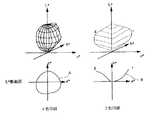
ここで、上記の標準的な色空間(L*a*b*空間)について簡単に説明しておく。L*a*b*空間はCIEが推薦するCIELABという色度図であり、L*が明度を表し、a*が赤又は緑の度合いを表し、b*が黄又は青の度合いを表す。図3にL*a*b*空間とその空間上に位置付けられる色の関係を模式的に示す。図中右から左へ走る横軸がa*軸であり、a*の値がマイナス側へ向かうほど緑色に近づき、プラス側へ向かうほど赤色に近づく。また、b*軸ではマイナス側へ向かうほど青色に近づき、プラス側へ向かうほど黄色に近づく。上下に走るL*軸は、最上部が白(全反射、L=100)を示し、最下部が黒(全吸収、L=0)を示す。そして、これら3軸の中心が中間色(灰色)となる。即ち、L*軸方向の移動は明度の変化を示し、a*b*平面上の半径方向の移動は彩度の変化を示し、a*b*平面上の周方向の移動は色相の変化を示す。なお、L*a*b*空間上の距離は色の近さに対応しており、距離が近いほど色が近いということができる。
【0020】
ICCが規定するプロファイルの内容の概略を図1に示す。デバイスの色特性を記述する部分の基本構成は、図1のように、前後にl次元のルックアップテーブル(以下、「LUT」とも呼ぶ。)を持つ、n次元→3次元又は3次元→n次元(nは色数)のLUTの形式である。即ち、n次元→3次元のプロファイルは、特定のデバイスのn次元色表記を標準的な3次元色空間(L*a*b*)と対応付ける。また、3次元→n次元のプロファイルは、標準的な3次元色空間(L*a*b*)を特定のデバイスのn次元の色表記と対応付ける。なお、前後の1次元LUTは、通常はリニア(入出力の値が同値)であるが、特殊な特性に設定してデバイスの経時変動の補正に用いられることもある。図1では、説明を簡単にするため、3色のデバイス(即ち、n=3)のLUTの形式を図示している。
【0021】
本発明で使用する印刷デバイス型プロファイルは、デバイスの色表記から標準の色空間での表記に変換するn次元→3次元LUTと、これと対になる、標準の色空間からデバイスの色表記に変換する3次元→n次元LUTを含む形式である。
【0022】
次に、上記のような形式の印刷型デバイスのプロファイルを、CMSでの色変換に使用する方法を図2に示す。ある印刷型デバイス(たとえばオフセット印刷機、CMYK4色)の色を、別の印刷型デバイス(たとえばデジタルプリンタ、CMYK4色)で再現する場合は、変換の目標プロファイルとしてオフセット印刷機のプロファイルを、目標の色を再現するデバイスのプロファイル(以下、「再現プロファイル」と呼ぶ。)としてデジタルプリンタのプロファイルを指定する。すると、CMSは、与えられた画像の色データについて、目標のオフセット印刷機のプロファイルの4次元→3次元LUTを使用して、オフセット印刷における色表記がL*a*b*空間上のどこに位置するかを算出する。次にCMSは、この色を再現するデジタルプリンタのデバイス色表記を、デジタルプリンタのプロファイルの3次元→4次元LUTを使用して算出する。CMSの色変換演算は、数学的には目標デバイスの色再現と出力先デバイスの色再現の写像を求めることに相当する。
【0023】
次に、上記プロファイルの作成方法について説明する。今、デジタルプリンタのプロファイルを作成する場合を考えると、目標デバイス(この例ではデジタルプリンタ)で各色(通常はCMYKの4色)の掛け合わせチャート画像を出力し、その各色の色測定を行って対応するL*a*b*の値を得る。これにより、各CMYKの掛け合わせ色とL*a*b*値の組み合わせとの対応が得られる。次に、この対応に基づいて、CMYKの掛け合わせの色に対するL*a*b*値のルックアップテーブル(以下、「LUT」とも呼ぶ。)を作成し、さらにそのLUTを逆算してL*a*b*値に対するCMYKの掛け合わせ色のLUTを作成する。そして両LUTを一つのファイルにまとめることにより、デジタルプリンタ用のプロファイルが得られる。
【0024】
次に、本発明による特色印刷用データの作成について説明する。図4に、4色分解データから2色分解データへの変換処理を模式的に示す。
【0025】
図4において、目標プロファイルは通常の4色分解データをL*a*b*値に変換するプロファイルであり、4次元から3次元へのプロファイルである。また、2色印刷用プロファイルはL*a*b*値を2色印刷用データに変換するプロファイルであり、3次元から2次元へのプロファイルである。2色印刷用プロファイルの構成を図5に示す。このプロファイルの作成方法は基本的に前述の4色印刷用プロファイルと同様である。即ち、2色印刷において使用するインキ色の掛け合わせ色チャートを目標デバイスで出力し、出力されたチャートの色測定を行って各色のL*a*b*値を得る。そして、当該2色からL*a*b*値へのLUTと、L*a*b*値から2色へのLUTを作成し、2色印刷用プロファイルとする。なお、図5においてC1及びC2は2色印刷において使用するインキの2色を指す。
【0026】
こうして作成された2色印刷用プロファイルがデータベースに登録される。通常の4色分解された画像について2色印刷を行う必要が生じた場合、データベースに記憶された4色分解データ及び上記の2色印刷用プロファイルを呼び出し、図3に示す流れで2色印刷用データへの変換を行う。これにより、データベース中に同一画像について4色分解データ及び2色分解データの両方を記憶しておく必要がなくなる。
【0027】
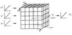
2色印刷用プロファイルは基本的に上記のように作成するが、4色の画像データと2色の画像データとでは再現できる色の範囲が異なるため、2色印刷用プロファイルではその調整を行う必要がある。この点について図6を参照して説明する。図6において左側は4色印刷により再現可能な色範囲をL*a*b*空間上に模式的に示した図であり、右側は2色印刷により再現できる色範囲を同じくL*a*b*空間上に模式的に示した図である。図6中の特性Aは4色印刷の色再現範囲であり、特性Bは2色印刷の色再現範囲である。図からも分かるように、2色印刷では表現できる色再現範囲に制限がある。4色印刷では色再現できる範囲が閉曲面(立体)になるのに対し、2色印刷では使用するインキ2色とその掛け合わせの色並びに紙の白色を含む曲面となる。よって、2色印刷ではL*a*b*空間内のある特定の色範囲しか再現できない。
【0028】
従って、4色印刷用データを2色印刷用データへ変換する際には、2色印刷で再現できない色を2色印刷で再現できる色へ何らかの規則に従って写像するように、2色印刷用プロファイルのLUTを構成しなければならない。写像のための規則について以下に説明する。
【0029】
図7に4色印刷用データを2色印刷用データへ変換するための規則の一つを示す。図7はL*a*b*空間上の2つの色(点C、D)を2色印刷用データへ変換する方法を示している(図を簡単にするためa*b*平面を見た図を表す)。具体的には、2色印刷では再現できない色に対しては、最も色の差の小さい色(最も近い色)に移動する。即ちL*a*b*空間の2色印刷の再現特性B上の最も距離の短い点に移動する。図7の例では、点Cの色は2色印刷で再現可能な範囲内(特性B上)に位置するので、そのままの色を使用できる。一方、点Dの色は特性B上に無いので、特性B上で点Dの色から最も距離の近い色(点D’)に移動する。この規則によれば、2色印刷用プロファイルにより変換された2色印刷用データでは、彩度が低くなる場合はあるものの、色相が大きく変化することはなく、階調のはっきりした画像となる。
【0030】
図8に更に他の例を示す。図8の例は、彩度を保ったまま色相を変化させる方法である。具体的には、使用する2色のインキ色による最高彩度の色の2点(g、r)とa*b*平面の中心(無彩色に対応)とにより構成される三角形に関し、2点g、rの中点とa*b*平面の中心との結ぶ分割線を仮定し、その分割線により規定される領域内で色相を回転させて、2色印刷で再現可能な特性上の点に写像する。次に、2色印刷で再現可能なそれぞれの色相において、明度と彩度が再現可能範囲から外れている点について、色相が変わらないようにL*=50、a*=b*=0の点の方向へ移動させ、2色印刷で再現可能な特性B上の点に写像する。この時、明度と彩度が再現可能範囲にある点についても、先に再現可能範囲外から移動した点の移動量と等比的に、L*=50、a*=b*=0の点の方向へ移動させる。これによって決まるL*a*b*の値を2色印刷での写像値とする。なお、実際にはインキの再現色は曲線、曲面となるが、演算を簡単化するために図のような直線、平面に近似する。実際の曲線、曲面上に乗らない値は、曲線、曲面に乗っている最も近い値に置き換えるのが良い。
【0031】
このように、2色印刷では再現できない色については、それらを2色印刷で再現可能な色に写像するための所定の規則を決定し、それらの関係を2色印刷用プロファイルのLUTに対応付けしておく。プロファイルは多次元LUTの構造であるので、そのような規則に従って写像位置をある程度自由に設定することができる。また、一度LUTを決定して2色印刷用プロファイルを作成した後、部分的に変更すべき色があれば、その色についてのLUTの内容を部分的に変更することにより2色印刷用プロファイルの内容を改善することができる。
【0032】
図9に単色印刷用プロファイルの構成を示す。単色印刷用プロファイルも、2色印刷用プロファイルと同様の考え方で作成することができる。最も単純な方法は、目標デバイスの4色印刷用プロファイルにより変換されたL*a*b*値から、L*値のみを0〜100%で正規化し、その値を1色(図9の色C1)として出力するプロファイルを作成する。
【0033】
また、図10にダブルトーン2色印刷用プロファイルの構成を示す。ダブルトーンとは、グラデーションをなめらかに再現するために濃さ又は色相の異なる2つのインキで画像を刷り重ねる方法をいう。この場合には、上述のようにL*a*b*値のうち、明度成分であるL*値のみを正規化し、白に相当する部分を出力0、黒に相当する部分を出力1として反転させてこれを第1色(色C1)とする。さらに、その1/2の値を第2色(色C2)とするように3次元から2次元へのプロファイルを作成する。これにより、ダブルトーン手法を施した2色印刷物を得ることができる。
【0034】
以上説明したように、2色印刷用又は単色印刷用のプロファイルを作成しておくことにより、4色印刷用の色分解データから容易に2色印刷又は単色印刷用の色データを得ることができる。従って、データベース内に同一の画像についての複数の色分解データを保持しておく必要が無くなる。
【0035】
次に、本発明の実施形態による2色印刷データ作成システムの構成を示す。図11において2色印刷作成システムは、スキャナ20及び画像データベース22を有する。スキャナ20は必要な画像を色分解して、通常はCMYKの4色印刷用の色分解データを出力する。この4色印刷用データは画像データベース22に記憶され、DTPシステム28による編集、レイアウト作業に供される。
【0036】
プロファイルデータベース26には、画像データベース22内に記憶された4色印刷用データを使用して作成された印刷原稿を2色印刷するための色変換に使用するプロファイルが記憶されている。具体的には、図4に示すように、目標プロファイルとして4色印刷用データからL*a*b*値への変換に使用するプロファイル、及び、L*a*b*値から2色印刷用データへの変換に使用する2色印刷用プロファイルが記憶されている。なお、本システムを前述の単色印刷及びダブルトーン印刷に使用する場合には、図9、10に示すような単色印刷用及びダブルトーン印刷用プロファイルがプロファイルデータベース26内に記憶されている。
【0037】
色変換部30は、上記のプロファイルを利用して4色印刷用データから2色印刷用データへの変換を行う部分であり、フィルム出力部32は2色印刷用データのフィルムを作成、出力する。
【0038】
次に、本システムによる処理について説明する。
【0039】
先ず、広告の企画が決定すると、作業内容管理部24にその内容が報告される。具体的には、その回の広告の表裏面の使用色、掲載商品などの情報が与えられる。作業内容管理部24はこの情報を基に画像データベース22から必要な画像データを読み出し、それらの画像が掲載される面の色情報と共にDTPシステム28へ供給する。DTPシステム28では画像の修正、レイアウトなどを行い、原稿データを作成して色変換部30へ送る。色変換部30は、作業内容管理部24から与えられた情報に基づいて色変換に使用するプロファイルをプロファイルデータベース26から呼び出し、原稿データの色変換を行う。これにより、4色印刷用データから2色印刷用データへの色変換が行われ、2色印刷用データがフィルム出力部32へ供給される。フィルム出力部32は、その2色印刷用データをフィルム出力する。これにより、広告などの2色印刷が可能となる。
【0040】
単色印刷などの他の特色印刷を行う場合は、プロファイルデータベース26から対応するプロファイルを読み出して変換部30による変換に使用すれば良い。
【0041】
以上説明したように、本発明によれば、安価なDTP製版システムを使用して、4色印刷用データから特色刷り用データへの画像色変換を行うことができる。よって、4色印刷用データのみを蓄積、管理すればよく、画像の管理が容易となる。また、特色印刷において使用するインキの色が変更になったような場合でも、新たなインキの組み合わせに対応するプロファイルを作成して記憶するだけでよく、新たな特色印刷用インキについての色分解処理を行う必要がない。よって、画像データベースに汎用的な4色分解データのみを記憶し、特色印刷用のプロファイルをプロファイルデータベースに用意することにより、多種の特色印刷を容易に行うことが可能となる。
【0042】
【発明の効果】
請求項1に記載の発明によれば、4色印刷用編集データを最も近い色の2色印刷用データに変換することができる。
【図面の簡単な説明】
【図1】カラーマネージメントシステムで使用するプロファイルの構成を模式的に示す図である。
【図2】カラーマネージメントシステムにおける色変換処理の流れを示す図である。
【図3】標準的な色空間(L*a*b*空間)を示す図である。
【図4】本発明における2色印刷用データの作成処理を模式的に示す図である。
【図5】2色印刷用プロファイルの構成を示す図である。
【図6】4色印刷と2色印刷による色再現範囲を模式的に示す図である。
【図7】4色印刷の色から2色印刷の色への写像方法の一例を示す図である。
【図8】4色印刷の色から2色印刷の色への写像方法の他の一例を示す図である
【図9】単色印刷用プロファイルの構成を示す図である。
【図10】ダブルトーン2色印刷用プロファイルの構成を示す図である。
【図11】本発明による2色印刷用データ作成システムの構成を示すブロック図である。
【符号の説明】
20…スキャナ
22…画像データベース
24…作業内容管理部
26…プロファイルデータベース
28…DTPシステム
30…色変換部
32…フィルム出力部[0001]
BACKGROUND OF THE INVENTION
The present invention relates to creation of spot color printing data, and more particularly to a technique for creating spot color printing image data from normal four-color printing image data.
[0002]
[Prior art]
2. Description of the Related Art Conventionally, in printing newspaper insert advertisements, two-color printing or single-color printing using special ink (hereinafter, also referred to as “special color printing”) has been frequently used in addition to the usual four-color process printing. Two-color printing is printed mainly using red and green (or red and blue) inks, but any two plates (mainly cyan and magenta) of the four-color separated image are used for image making. For example, in the case of red and green printing colors, the image portion uses a cyan plate as a green plate and a magenta plate as a red plate. In the case of monochrome printing, the monochrome separation of the image is performed separately from the color data separated by the four colors, and the monochrome image is used.
[0003]
In recent years, in the production of advertisements, it has been generally performed to register and store product images and the like in a database, and call them up and use them as necessary. However, in the layout of advertisements, various printing colors are used depending on the balance between the contents of each advertisement project and the cost. For example, there are cases where the front surface of an advertisement is printed in four colors and the back surface is printed in two colors, or the surface is printed in two colors and the back surface is printed in a single color, and the composition of the printed colors frequently changes. For this reason, as the product image data, four-color separated data, two-color separated data, and single-color (monochrome) data are properly used as necessary.
[0004]
[Problems to be solved by the invention]
In the case of two-color plate making mainly used for advertisement, depending on the color tone of a subject in an image to be printed, the tone may not be sufficiently reproduced with the two-color color. Therefore, to correct this, the image is color-separated into two colors. At that time, instead of the four-color separation of the normal process printing, the color separation is performed by changing the setting according to the color of the ink used in the two-color printing. Will do. In this case, since a function such as so-called auto setup of the scanner cannot be used, it is necessary for an expert to perform color separation setting work after trial and error, which places a heavy burden on the operator and also requires time.
[0005]
In addition, if two of the four color-separated versions as described above are used, tone reproduction failure may occur due to loss of the tone of the unused version. It is necessary to keep it. In other words, with respect to an image of a product in which a tone reproduction failure occurs, three types of color data, four-color separated color data, two-color separated color data, and single color data for the same image must be stored in the database. Cases arise. However, if a plurality of pieces of image data of the same product are stored, there is a problem that the management of the data becomes complicated and an accident due to a mistake in data is likely to occur at the time of plate making.
[0006]
The present invention has been made in view of the above points, and can create data for spot color printing that can easily create data for spot color printing such as two-color printing and single-color printing from ordinary four-color separated data. It is an object to provide an apparatus.
[0007]
[Means for Solving the Problems]
The invention according to
[0008]
According to the spot color printing data creation apparatus configured as described above, spotcolor printing data can be easily created from the four color printing data stored in the first storage unit, and two-color printing is performed as it is. Color data that cannot be converted to 4 can be converted from the edit data for four-color printing to the data for two-color printing of the closest color.
[0015]
DETAILED DESCRIPTION OF THE INVENTION
First, prior to description of embodiments of the present invention, a color management system used in the present invention will be described.
[0016]
A color management system (hereinafter also referred to as “CMS”) refers to a combination of these devices when there are a plurality of printing apparatuses (collectively referred to as “devices”) such as scanners, printing machines, and digital printers. This is a function that realizes output color matching. In recent years, a color management system has been realized at the level of an operating system (OS) of a personal computer, and even a DTP (Desk Top Publishing) system can easily perform color conversion without depending on an application.
[0017]
Normally, when the same image data (for example, CMYK color data) is output by different devices (for example, printing and electrostatic copying methods), the colors of the actually obtained output products are different. This is because the color description of CMYK does not directly describe colors expressed by human senses, but describes only the output signals of the device, so CMYK and RGB are “device dependent”. Color ”. On the other hand, “colors expressed as human sensations” that are absolutely independent of devices are described in standard color spaces (XYZ and L * a * b *) defined by the CIE (International Commission on Illumination). can do. The function of CMS is the description data called the profile (conversion parameters used when performing color conversion), which color corresponds to the color such as CMYK or RGB of each device in the standard color space. The output product of the same color can be obtained by different devices by performing color conversion on the image while referring to the profile.
[0018]
The profile is a conversion parameter for converting the color of a specific device (for example, an offset printer, a color printer, etc.) into the standard color space (L * a * b * space) described above. The profile format is being internationally standardized by an organization called ICC (International Color Consotium) (see ICC Profile Specification).
[0019]
Here, the standard color space (L * a * b * space) will be briefly described. The L * a * b * space is a chromaticity diagram called CIELAB recommended by CIE, where L * represents lightness, a * represents the degree of red or green, and b * represents the degree of yellow or blue. FIG. 3 schematically shows the relationship between the L * a * b * space and the colors positioned on the space. The horizontal axis running from right to left in the figure is the a * axis, and the closer the value of a * is to the minus side, the closer to green, and the closer to the plus side, the closer to red. On the b * axis, the closer to the minus side, the closer to blue, and the closer to the plus side, the closer to yellow. The L * axis running up and down shows white (total reflection, L = 100) at the top and black (total absorption, L = 0) at the bottom. The center of these three axes is an intermediate color (gray). That is, movement in the L * axis direction indicates a change in brightness, movement in the radial direction on the a * b * plane indicates a change in saturation, and movement in the circumferential direction on the a * b * plane indicates a change in hue. Show. The distance in the L * a * b * space corresponds to the closeness of the color, and it can be said that the closer the distance is, the closer the color is.
[0020]
An outline of the contents of the profile defined by the ICC is shown in FIG. As shown in FIG. 1, the basic configuration of the part describing the color characteristics of the device is n-dimensional → three-dimensional or three-dimensional → n having an l-dimensional lookup table (hereinafter also referred to as “LUT”). It is a LUT format of dimension (n is the number of colors). In other words, the n-dimensional → three-dimensional profile associates the n-dimensional color representation of a specific device with the standard three-dimensional color space (L * a * b *). The three-dimensional → n-dimensional profile associates a standard three-dimensional color space (L * a * b *) with the n-dimensional color notation of a specific device. The front and rear one-dimensional LUTs are usually linear (input / output values are the same value), but may be set to special characteristics and used to correct device aging. In FIG. 1, the LUT format of a three-color device (that is, n = 3) is illustrated for simplicity of explanation.
[0021]
The printing device type profile used in the present invention is an n-dimensional → three-dimensional LUT for converting a device color expression into a standard color space expression, and a standard color space to a device color expression. This is a format including a three-dimensional → n-dimensional LUT to be converted.
[0022]
Next, FIG. 2 shows a method of using a profile of a printing type device having the above format for color conversion in CMS. When reproducing the color of one printing type device (for example, offset printer, CMYK 4 colors) on another printing type device (for example, digital printer, CMYK 4 colors), the profile of the offset printing machine is used as the target profile for conversion. A digital printer profile is designated as a profile of a device that reproduces colors (hereinafter referred to as a “reproduction profile”). Then, the CMS uses the 4D → 3D LUT of the target offset printer profile for the color data of the given image, and where the color notation in offset printing is located in the L * a * b * space. Calculate what to do. The CMS then calculates the device color notation of the digital printer that reproduces this color using the 3D → 4D LUT of the profile of the digital printer. The color conversion operation of CMS is mathematically equivalent to obtaining a color reproduction map of the target device and the output device.
[0023]
Next, a method for creating the profile will be described. Considering the case of creating a profile for a digital printer, a target chart (digital printer in this example) outputs a multiplication chart image of each color (usually four colors of CMYK), and measures the color of each color. Get the corresponding L * a * b * value. As a result, correspondence between each CMYK multiplication color and a combination of L * a * b * values is obtained. Next, based on this correspondence, a lookup table (hereinafter also referred to as “LUT”) of L * a * b * values for the CMYK multiplied colors is created, and the LUT is calculated by back-calculating L *. Create an LUT of CMYK multiplicative colors for a * b * values. A profile for a digital printer is obtained by combining both LUTs into one file.
[0024]
Next, creation of spot color printing data according to the present invention will be described. FIG. 4 schematically shows conversion processing from four-color separation data to two-color separation data.
[0025]
In FIG. 4, the target profile is a profile for converting normal four-color separation data into L * a * b * values, and is a profile from four dimensions to three dimensions. The two-color printing profile is a profile for converting L * a * b * values into two-color printing data, and is a three-dimensional to two-dimensional profile. The configuration of the two-color printing profile is shown in FIG. The profile creation method is basically the same as the above-described four-color printing profile. In other words, the target color device outputs a combined color chart of ink colors used in two-color printing, and performs color measurement on the output chart to obtain L * a * b * values for each color. Then, an LUT from the two colors to L * a * b * values and an LUT from the L * a * b * values to two colors are created and set as a two-color printing profile. In FIG. 5, C1 and C2 indicate two colors of ink used in two-color printing.
[0026]
The two-color printing profile created in this way is registered in the database. When it becomes necessary to perform two-color printing on a normal four-color-separated image, the four-color separation data stored in the database and the above two-color printing profile are called, and the two-color printing is performed according to the flow shown in FIG. Perform conversion to data. This eliminates the need to store both the four-color separation data and the two-color separation data for the same image in the database.
[0027]
The two-color printing profile is basically created as described above. However, the four-color image data and the two-color image data have different reproducible color ranges, so the two-color printing profile needs to be adjusted. There is. This point will be described with reference to FIG. In FIG. 6, the left side is a diagram schematically showing the color range reproducible by four-color printing on the L * a * b * space, and the right side is the color range reproducible by two-color printing. * It is the figure typically shown on the space. A characteristic A in FIG. 6 is a color reproduction range of four-color printing, and a characteristic B is a color reproduction range of two-color printing. As can be seen from the figure, the color reproduction range that can be expressed by two-color printing is limited. In the four-color printing, the color reproducible range is a closed curved surface (three-dimensional), whereas in the two-color printing, a curved surface including two inks to be used, a color obtained by multiplying them, and white of paper is used. Therefore, only a specific color range in the L * a * b * space can be reproduced by two-color printing.
[0028]
Therefore, when converting 4-color printing data to 2-color printing data, the 2-color printing profile is set so that colors that cannot be reproduced by 2-color printing are mapped according to some rules to colors that can be reproduced by 2-color printing. The LUT must be configured. The rules for mapping are described below.
[0029]
FIG. 7 shows one of the rules for converting 4-color printing data into 2-color printing data. FIG. 7 shows a method of converting two colors (points C and D) in the L * a * b * space into data for two-color printing (for the sake of simplicity, the a * b * plane is viewed. Represents the figure). Specifically, for a color that cannot be reproduced by two-color printing, the color moves to the color with the smallest color difference (the closest color). That is, the point moves to the shortest point on the reproduction characteristic B of the two-color printing in the L * a * b * space. In the example of FIG. 7, the color of the point C is located within a range that can be reproduced by two-color printing (on the characteristic B), so that the color as it is can be used. On the other hand, since the color of the point D is not on the characteristic B, the color moves from the color of the point D to the closest color (point D ′) on the characteristic B. According to this rule, in the two-color printing data converted by the two-color printing profile, although the saturation may be lowered, the hue does not change greatly and an image with clear gradation is obtained.
[0030]
FIG. 8 shows still another example. The example of FIG. 8 is a method of changing the hue while maintaining the saturation. Specifically, two points on a triangle composed of two points (g, r) of the highest saturation color by the two ink colors used and the center of the a * b * plane (corresponding to an achromatic color) Assuming a dividing line connecting the midpoint of g, r and the center of the a * b * plane, the hue is rotated within the area defined by the dividing line, and the characteristic point that can be reproduced by two-color printing To map. Next, in each hue that can be reproduced by two-color printing, the point where L * = 50 and a * = b * = 0 so that the hue does not change at the point where the lightness and saturation are out of the reproducible range. To a point on the characteristic B that can be reproduced by two-color printing. At this time, even when the lightness and saturation are within the reproducible range, the point of L * = 50 and a * = b * = 0 in proportion to the amount of movement of the point previously moved from outside the reproducible range. Move in the direction of. The value of L * a * b * determined by this is used as the mapping value for two-color printing. Actually, the reproduced color of the ink is a curve or a curved surface, but approximates a straight line or a plane as shown in the figure in order to simplify the calculation. Values that are not on the actual curve or curved surface should be replaced with the closest values on the curve or curved surface.
[0031]
Thus, for colors that cannot be reproduced by two-color printing, a predetermined rule for mapping them to colors that can be reproduced by two-color printing is determined, and the relationship is associated with the LUT of the two-color printing profile. Keep it. Since the profile has a multi-dimensional LUT structure, the mapping position can be freely set to some extent according to such rules. Further, once a LUT is determined and a two-color printing profile is created, if there is a color to be partially changed, the contents of the two-color printing profile are changed by partially changing the contents of the LUT for that color. The content can be improved.
[0032]
FIG. 9 shows the configuration of a monochrome printing profile. A monochrome printing profile can be created in the same way as a two-color printing profile. The simplest method is to normalize only the L * value from 0 to 100% from the L * a * b * value converted by the four-color printing profile of the target device, and set that value to one color (the color in FIG. 9). Create a profile to be output as C1).
[0033]
FIG. 10 shows the configuration of a double-tone two-color printing profile. The double tone is a method in which an image is printed with two inks having different densities or hues in order to smoothly reproduce a gradation. In this case, as described above, of the L * a * b * values, only the L * value, which is a lightness component, is normalized, and the portion corresponding to white is
[0034]
As described above, by creating a profile for two-color printing or single-color printing, color data for two-color printing or single-color printing can be easily obtained from the color separation data for four-color printing. . Therefore, it is not necessary to store a plurality of color separation data for the same image in the database.
[0035]
Next, the configuration of the two-color print data creation system according to the embodiment of the present invention is shown. In FIG. 11, the two-color print creation system includes a
[0036]
The
[0037]
The
[0038]
Next, processing by this system will be described.
[0039]
First, when an advertisement plan is determined, the content is reported to the work
[0040]
When performing other special color printing such as single color printing, the corresponding profile may be read from the
[0041]
As described above, according to the present invention, image color conversion from four-color printing data to special color printing data can be performed using an inexpensive DTP plate making system. Therefore, it is sufficient to store and manage only four-color printing data, and image management becomes easy. Even if the color of ink used in special color printing is changed, it is only necessary to create and store a profile corresponding to a new ink combination, and color separation processing for new special color printing ink. There is no need to do. Therefore, by storing only general-purpose four-color separation data in the image database and preparing a profile for spot color printing in the profile database, it becomes possible to easily perform various kinds of spot color printing.
[0042]
【The invention's effect】
According to the first aspect of the present invention, thefour-color print editing data can be converted into the closest two-color print data.
[Brief description of the drawings]
FIG. 1 is a diagram schematically showing a configuration of a profile used in a color management system.
FIG. 2 is a diagram illustrating a flow of color conversion processing in a color management system.
FIG. 3 is a diagram illustrating a standard color space (L * a * b * space).
FIG. 4 is a diagram schematically showing a process for creating data for two-color printing in the present invention.
FIG. 5 is a diagram illustrating a configuration of a two-color printing profile.
FIG. 6 is a diagram schematically illustrating a color reproduction range by four-color printing and two-color printing.
FIG. 7 is a diagram illustrating an example of a mapping method from four-color printing colors to two-color printing colors.
FIG. 8 is a diagram showing another example of a mapping method from four-color printing colors to two-color printing colors. FIG. 9 is a diagram showing a configuration of a single-color printing profile.
FIG. 10 is a diagram illustrating a configuration of a double tone two-color printing profile.
FIG. 11 is a block diagram showing the configuration of a two-color printing data creation system according to the present invention.
[Explanation of symbols]
DESCRIPTION OF
Claims (1)
Translated fromJapanese前記4色印刷用データを前記第1の記憶部から読み出し、編集して、4色印刷用編集データを作成する編集手段と、
カラーマネージメントシステムを利用して、前記4色印刷用データを特色印刷用データに変換するためのプロファイルであって、前記4色印刷用データをL*a*b*空間における色データに変換するための第1のプロファイルと、前記L*a*b*空間における色データを前記特色印刷用データに変換するための第2のプロファイルと、を含むプロファイルを記憶する第2の記憶部と、
前記第2の記憶部から読み出した前記第1のプロファイルを利用して前記4色印刷用編集データを前記L*a*b*空間における色データに変換する手段と、前記第2の記憶部から読み出した前記第2のプロファイルを利用して前記L*a*b*空間における色データを前記特色印刷用編集データに変換する手段と、を有する変換手段と、
を備え、
前記変換手段は、前記4色印刷用編集データのうち2色印刷において再現可能な範囲に含まれないデータを、2色印刷において再現可能な範囲内のデータに写像する写像手段を更に備え、
前記写像手段は、前記4色印刷用編集データのうち2色印刷において再現可能な範囲に含まれないデータを、前記2色印刷において再現可能な範囲内のデータのうち前記L*a*b*空間上で最短距離に位置するデータに写像する特色印刷用データ作成装置。A first storage unit for storing four-color printing data;
Editing means for reading out and editing the four-color printing data from the first storage unit to create four-color printing editing data;
A profile for converting the four-color printing data into spot color printing data using a color management system, for converting the four-color printing data into color data in an L * a * b * space. A second storage unit for storing a profile including: a first profile of: a second profile for converting color data in the L * a * b * space into the spot color printing data;
Means for converting the edit data for four-color printing into color data in the L * a * b * space using the first profile read from the second storage, and from the second storage Means for converting color data in the L * a * b * space into the edit data for spot color printing using the read second profile;
With
The conversion means further comprises mapping means for mapping data that is not included in the reproducible range in two-color printing out of the edit data for four-color printing to data in a range reproducible in two-color printing,
The mapping means includes data that is not included in the range that can be reproduced by two-color printing in the editing data for four-color printing, and data that is within the range that can be reproduced by two-color printing. A special color printing data creation device that maps to data located at the shortest distance in space.
Priority Applications (1)
| Application Number | Priority Date | Filing Date | Title |
|---|---|---|---|
| JP26649498AJP4083311B2 (en) | 1998-09-21 | 1998-09-21 | Special color printing data creation device |
Applications Claiming Priority (1)
| Application Number | Priority Date | Filing Date | Title |
|---|---|---|---|
| JP26649498AJP4083311B2 (en) | 1998-09-21 | 1998-09-21 | Special color printing data creation device |
Publications (2)
| Publication Number | Publication Date |
|---|---|
| JP2000101856A JP2000101856A (en) | 2000-04-07 |
| JP4083311B2true JP4083311B2 (en) | 2008-04-30 |
Family
ID=17431718
Family Applications (1)
| Application Number | Title | Priority Date | Filing Date |
|---|---|---|---|
| JP26649498AExpired - Fee RelatedJP4083311B2 (en) | 1998-09-21 | 1998-09-21 | Special color printing data creation device |
Country Status (1)
| Country | Link |
|---|---|
| JP (1) | JP4083311B2 (en) |
Cited By (1)
| Publication number | Priority date | Publication date | Assignee | Title |
|---|---|---|---|---|
| US9635217B2 (en) | 2014-10-21 | 2017-04-25 | Kyocera Document Solutions Inc. | Image forming apparatus that converts input color value to representative color value within constant hue plane and uses converted color value as printing color value, and image forming method |
Families Citing this family (7)
| Publication number | Priority date | Publication date | Assignee | Title |
|---|---|---|---|---|
| US7474446B2 (en) | 2003-12-03 | 2009-01-06 | Seiko Epson Corporation | Color reduction processing apparatus, printer control device, color reduction method, and printer control method |
| KR20080074098A (en)* | 2005-11-02 | 2008-08-12 | 다이니폰 인사츠 가부시키가이샤 | Thermal recording apparatus, image forming method and phosphide |
| JP2007125768A (en)* | 2005-11-02 | 2007-05-24 | Dainippon Printing Co Ltd | Thermal recording apparatus, image forming method, and intermediate transfer medium |
| JP2007268730A (en)* | 2006-03-30 | 2007-10-18 | Dainippon Printing Co Ltd | Thermal recording apparatus, image forming method and printed matter |
| JP2007253607A (en)* | 2005-11-02 | 2007-10-04 | Dainippon Printing Co Ltd | Thermal recording apparatus, image forming method and printed matter |
| JP4803010B2 (en)* | 2006-12-07 | 2011-10-26 | 凸版印刷株式会社 | 2-color printing data creation method |
| CN102529405B (en)* | 2010-12-24 | 2014-07-23 | 北大方正集团有限公司 | Double-color double-sided printing method and device |
- 1998
- 1998-09-21JPJP26649498Apatent/JP4083311B2/ennot_activeExpired - Fee Related
Cited By (1)
| Publication number | Priority date | Publication date | Assignee | Title |
|---|---|---|---|---|
| US9635217B2 (en) | 2014-10-21 | 2017-04-25 | Kyocera Document Solutions Inc. | Image forming apparatus that converts input color value to representative color value within constant hue plane and uses converted color value as printing color value, and image forming method |
Also Published As
| Publication number | Publication date |
|---|---|
| JP2000101856A (en) | 2000-04-07 |
Similar Documents
| Publication | Publication Date | Title |
|---|---|---|
| EP0929190B1 (en) | Method and apparatus for correcting luminance and chrominance data in digital color images | |
| US7032517B2 (en) | Method for the reproduction of spot colors with primary printing inks and secondary printing inks | |
| US5881211A (en) | Data conversion table changing | |
| US5305119A (en) | Color printer calibration architecture | |
| US6657746B1 (en) | Look-up table constructing method and color conversion apparatus | |
| US8218206B2 (en) | Color conversion using transformed gamuts | |
| KR20120024670A (en) | Methods and systems for multicolor process printing employing both process colors and spot colors in the process ink set | |
| JPH08116456A (en) | Image processing unit | |
| US7506584B2 (en) | Method for producing a proof for a printing process having more than four printing inks | |
| US6922197B2 (en) | Method of generating color separation table | |
| JP2001136401A (en) | Color separated image correction method, chart ink jet printer, color separated image correction device and recording medium | |
| JP4083311B2 (en) | Special color printing data creation device | |
| EP1289268A2 (en) | Automatic color map conversion | |
| JP2000062253A (en) | Special color printing profile creation method and special color printing manuscript proof print creation device | |
| US7605945B2 (en) | Color reproduction definition creating method and color conversion method | |
| JP2001053976A (en) | Multicolor reproduction color correction device and multicolor proofing device | |
| JP4522555B2 (en) | Special color halftone output device | |
| US7495797B2 (en) | Color conversion definition coupling apparatus, and color conversion definition coupling program storage medium | |
| US20050213127A1 (en) | Color adjusting method, color image forming method, and color image forming device | |
| JP2005073054A (en) | Color chart creation apparatus and color chart creation method | |
| US20060072130A1 (en) | Method and system using gamut mapping templates to derive actual color gamut mapping | |
| JP3790204B2 (en) | Color image processing apparatus and color image processing method | |
| JP2003149796A (en) | Color proof generation system, image processor, output device, color proof generating method, program for implementing the method, and information recording medium where the program is recorded | |
| US20070279715A1 (en) | Color conversion definition creating apparatus, and color conversion definition creating program storage medium | |
| JP2710782B2 (en) | Color correction processing method |
Legal Events
| Date | Code | Title | Description |
|---|---|---|---|
| A621 | Written request for application examination | Free format text:JAPANESE INTERMEDIATE CODE: A621 Effective date:20050916 | |
| A977 | Report on retrieval | Free format text:JAPANESE INTERMEDIATE CODE: A971007 Effective date:20070222 | |
| A131 | Notification of reasons for refusal | Free format text:JAPANESE INTERMEDIATE CODE: A131 Effective date:20070417 | |
| A521 | Written amendment | Free format text:JAPANESE INTERMEDIATE CODE: A523 Effective date:20070615 | |
| RD03 | Notification of appointment of power of attorney | Free format text:JAPANESE INTERMEDIATE CODE: A7423 Effective date:20071011 | |
| A131 | Notification of reasons for refusal | Free format text:JAPANESE INTERMEDIATE CODE: A131 Effective date:20071127 | |
| A521 | Written amendment | Free format text:JAPANESE INTERMEDIATE CODE: A523 Effective date:20080115 | |
| TRDD | Decision of grant or rejection written | ||
| A01 | Written decision to grant a patent or to grant a registration (utility model) | Free format text:JAPANESE INTERMEDIATE CODE: A01 Effective date:20080212 | |
| A61 | First payment of annual fees (during grant procedure) | Free format text:JAPANESE INTERMEDIATE CODE: A61 Effective date:20080213 | |
| R150 | Certificate of patent or registration of utility model | Free format text:JAPANESE INTERMEDIATE CODE: R150 | |
| FPAY | Renewal fee payment (event date is renewal date of database) | Free format text:PAYMENT UNTIL: 20110222 Year of fee payment:3 | |
| FPAY | Renewal fee payment (event date is renewal date of database) | Free format text:PAYMENT UNTIL: 20110222 Year of fee payment:3 | |
| FPAY | Renewal fee payment (event date is renewal date of database) | Free format text:PAYMENT UNTIL: 20120222 Year of fee payment:4 | |
| LAPS | Cancellation because of no payment of annual fees |