JP4082765B2 - Three-piece solid golf ball - Google Patents
Three-piece solid golf ballDownload PDFInfo
- Publication number
- JP4082765B2 JP4082765B2JP26859897AJP26859897AJP4082765B2JP 4082765 B2JP4082765 B2JP 4082765B2JP 26859897 AJP26859897 AJP 26859897AJP 26859897 AJP26859897 AJP 26859897AJP 4082765 B2JP4082765 B2JP 4082765B2
- Authority
- JP
- Japan
- Prior art keywords
- golf ball
- ball
- putter
- kgf
- core
- Prior art date
- Legal status (The legal status is an assumption and is not a legal conclusion. Google has not performed a legal analysis and makes no representation as to the accuracy of the status listed.)
- Expired - Fee Related
Links
- 239000007787solidSubstances0.000titleclaimsdescription22
- 229920001971elastomerPolymers0.000claimsdescription13
- 239000005060rubberSubstances0.000claimsdescription13
- 229920002725thermoplastic elastomerPolymers0.000claimsdescription8
- 229920002635polyurethanePolymers0.000claimsdescription4
- 239000004814polyurethaneSubstances0.000claimsdescription4
- 239000000203mixtureSubstances0.000description16
- 229920005989resinPolymers0.000description12
- 239000011347resinSubstances0.000description12
- 229920000554ionomerPolymers0.000description10
- 230000000052comparative effectEffects0.000description9
- 238000000034methodMethods0.000description8
- 239000003795chemical substances by applicationSubstances0.000description7
- 150000002500ionsChemical class0.000description7
- TZCXTZWJZNENPQ-UHFFFAOYSA-Lbarium sulfateChemical compound[Ba+2].[O-]S([O-])(=O)=OTZCXTZWJZNENPQ-UHFFFAOYSA-L0.000description6
- 229910021645metal ionInorganic materials0.000description6
- 230000001133accelerationEffects0.000description5
- 239000002585baseSubstances0.000description5
- 238000007906compressionMethods0.000description5
- 230000006835compressionEffects0.000description5
- 239000000945fillerSubstances0.000description5
- 239000000463materialSubstances0.000description5
- 229910052751metalInorganic materials0.000description5
- 239000002184metalSubstances0.000description5
- 150000003839saltsChemical class0.000description5
- 229910001415sodium ionInorganic materials0.000description5
- VTYYLEPIZMXCLO-UHFFFAOYSA-LCalcium carbonateChemical compound[Ca+2].[O-]C([O-])=OVTYYLEPIZMXCLO-UHFFFAOYSA-L0.000description4
- XLOMVQKBTHCTTD-UHFFFAOYSA-NZinc monoxideChemical compound[Zn]=OXLOMVQKBTHCTTD-UHFFFAOYSA-N0.000description4
- 230000003712anti-aging effectEffects0.000description4
- 150000001732carboxylic acid derivativesChemical class0.000description4
- 238000002156mixingMethods0.000description4
- 229920002857polybutadienePolymers0.000description4
- 239000011701zincSubstances0.000description4
- 230000005484gravityEffects0.000description3
- 229910001416lithium ionInorganic materials0.000description3
- 238000010998test methodMethods0.000description3
- XMNIXWIUMCBBBL-UHFFFAOYSA-N2-(2-phenylpropan-2-ylperoxy)propan-2-ylbenzeneChemical compoundC=1C=CC=CC=1C(C)(C)OOC(C)(C)C1=CC=CC=C1XMNIXWIUMCBBBL-UHFFFAOYSA-N0.000description2
- 229920002943EPDM rubberPolymers0.000description2
- JOYRKODLDBILNP-UHFFFAOYSA-NEthyl urethaneChemical compoundCCOC(N)=OJOYRKODLDBILNP-UHFFFAOYSA-N0.000description2
- 206010016322Feeling abnormalDiseases0.000description2
- 244000043261Hevea brasiliensisSpecies0.000description2
- ZOKXTWBITQBERF-UHFFFAOYSA-NMolybdenumChemical compound[Mo]ZOKXTWBITQBERF-UHFFFAOYSA-N0.000description2
- FKNQFGJONOIPTF-UHFFFAOYSA-NSodium cationChemical compound[Na+]FKNQFGJONOIPTF-UHFFFAOYSA-N0.000description2
- PPBRXRYQALVLMV-UHFFFAOYSA-NStyreneChemical compoundC=CC1=CC=CC=C1PPBRXRYQALVLMV-UHFFFAOYSA-N0.000description2
- GWEVSGVZZGPLCZ-UHFFFAOYSA-NTitan oxideChemical compoundO=[Ti]=OGWEVSGVZZGPLCZ-UHFFFAOYSA-N0.000description2
- PTFCDOFLOPIGGS-UHFFFAOYSA-NZinc dicationChemical compound[Zn+2]PTFCDOFLOPIGGS-UHFFFAOYSA-N0.000description2
- 239000000654additiveSubstances0.000description2
- 230000015572biosynthetic processEffects0.000description2
- 229910000019calcium carbonateInorganic materials0.000description2
- 229910001424calcium ionInorganic materials0.000description2
- 229920001577copolymerPolymers0.000description2
- 239000003431cross linking reagentSubstances0.000description2
- 229920005648ethylene methacrylic acid copolymerPolymers0.000description2
- 229920006226ethylene-acrylic acidPolymers0.000description2
- 238000001746injection mouldingMethods0.000description2
- 229910001425magnesium ionInorganic materials0.000description2
- 238000005259measurementMethods0.000description2
- 229920003052natural elastomerPolymers0.000description2
- 229920001194natural rubberPolymers0.000description2
- 230000003472neutralizing effectEffects0.000description2
- 150000001451organic peroxidesChemical class0.000description2
- 239000000843powderSubstances0.000description2
- 238000000926separation methodMethods0.000description2
- 229920003051synthetic elastomerPolymers0.000description2
- WFKWXMTUELFFGS-UHFFFAOYSA-NtungstenChemical compound[W]WFKWXMTUELFFGS-UHFFFAOYSA-N0.000description2
- 239000011787zinc oxideSubstances0.000description2
- SMZOUWXMTYCWNB-UHFFFAOYSA-N2-(2-methoxy-5-methylphenyl)ethanamineChemical compoundCOC1=CC=C(C)C=C1CCNSMZOUWXMTYCWNB-UHFFFAOYSA-N0.000description1
- NIXOWILDQLNWCW-UHFFFAOYSA-N2-Propenoic acidNatural productsOC(=O)C=CNIXOWILDQLNWCW-UHFFFAOYSA-N0.000description1
- GPNYZBKIGXGYNU-UHFFFAOYSA-N2-tert-butyl-6-[(3-tert-butyl-5-ethyl-2-hydroxyphenyl)methyl]-4-ethylphenolChemical compoundCC(C)(C)C1=CC(CC)=CC(CC=2C(=C(C=C(CC)C=2)C(C)(C)C)O)=C1OGPNYZBKIGXGYNU-UHFFFAOYSA-N0.000description1
- 239000005063High cis polybutadieneSubstances0.000description1
- FYYHWMGAXLPEAU-UHFFFAOYSA-NMagnesiumChemical compound[Mg]FYYHWMGAXLPEAU-UHFFFAOYSA-N0.000description1
- CERQOIWHTDAKMF-UHFFFAOYSA-NMethacrylic acidChemical compoundCC(=C)C(O)=OCERQOIWHTDAKMF-UHFFFAOYSA-N0.000description1
- 239000005062PolybutadieneSubstances0.000description1
- HCHKCACWOHOZIP-UHFFFAOYSA-NZincChemical compound[Zn]HCHKCACWOHOZIP-UHFFFAOYSA-N0.000description1
- 239000006096absorbing agentSubstances0.000description1
- 229910001413alkali metal ionInorganic materials0.000description1
- 230000003796beautyEffects0.000description1
- 238000005282brighteningMethods0.000description1
- FACXGONDLDSNOE-UHFFFAOYSA-Nbuta-1,3-diene;styreneChemical groupC=CC=C.C=CC1=CC=CC=C1.C=CC1=CC=CC=C1FACXGONDLDSNOE-UHFFFAOYSA-N0.000description1
- 125000004432carbon atomChemical groupC*0.000description1
- 239000003086colorantSubstances0.000description1
- 238000013329compoundingMethods0.000description1
- 230000007423decreaseEffects0.000description1
- LSXWFXONGKSEMY-UHFFFAOYSA-Ndi-tert-butyl peroxideChemical compoundCC(C)(C)OOC(C)(C)CLSXWFXONGKSEMY-UHFFFAOYSA-N0.000description1
- 239000006185dispersionSubstances0.000description1
- 238000009826distributionMethods0.000description1
- 230000000694effectsEffects0.000description1
- 125000003700epoxy groupChemical group0.000description1
- 238000009472formulationMethods0.000description1
- 125000002887hydroxy groupChemical group[H]O*0.000description1
- 230000001771impaired effectEffects0.000description1
- 238000002347injectionMethods0.000description1
- 239000007924injectionSubstances0.000description1
- 238000004898kneadingMethods0.000description1
- 239000004611light stabiliserSubstances0.000description1
- 239000011777magnesiumSubstances0.000description1
- 229910052749magnesiumInorganic materials0.000description1
- 238000004519manufacturing processMethods0.000description1
- 238000000465mouldingMethods0.000description1
- 239000003973paintSubstances0.000description1
- 238000010422paintingMethods0.000description1
- 229920002647polyamidePolymers0.000description1
- 229920000728polyesterPolymers0.000description1
- 229920001195polyisoprenePolymers0.000description1
- 229920000642polymerPolymers0.000description1
- 238000002360preparation methodMethods0.000description1
- 238000003825pressingMethods0.000description1
- 239000000126substanceSubstances0.000description1
- 239000005061synthetic rubberSubstances0.000description1
- 239000004408titanium dioxideSubstances0.000description1
- 238000004073vulcanizationMethods0.000description1
- 239000002023woodSubstances0.000description1
- 229910052725zincInorganic materials0.000description1
- XKMZOFXGLBYJLS-UHFFFAOYSA-Lzinc;prop-2-enoateChemical compound[Zn+2].[O-]C(=O)C=C.[O-]C(=O)C=CXKMZOFXGLBYJLS-UHFFFAOYSA-L0.000description1
- 150000007934α,β-unsaturated carboxylic acidsChemical class0.000description1
Images

Classifications
- A—HUMAN NECESSITIES
- A63—SPORTS; GAMES; AMUSEMENTS
- A63B—APPARATUS FOR PHYSICAL TRAINING, GYMNASTICS, SWIMMING, CLIMBING, OR FENCING; BALL GAMES; TRAINING EQUIPMENT
- A63B37/00—Solid balls; Rigid hollow balls; Marbles
- A63B37/0003—Golf balls
- A—HUMAN NECESSITIES
- A63—SPORTS; GAMES; AMUSEMENTS
- A63B—APPARATUS FOR PHYSICAL TRAINING, GYMNASTICS, SWIMMING, CLIMBING, OR FENCING; BALL GAMES; TRAINING EQUIPMENT
- A63B37/00—Solid balls; Rigid hollow balls; Marbles
- A63B37/0003—Golf balls
- A63B37/0023—Covers
- A63B37/0029—Physical properties
- A63B37/0031—Hardness
- A—HUMAN NECESSITIES
- A63—SPORTS; GAMES; AMUSEMENTS
- A63B—APPARATUS FOR PHYSICAL TRAINING, GYMNASTICS, SWIMMING, CLIMBING, OR FENCING; BALL GAMES; TRAINING EQUIPMENT
- A63B37/00—Solid balls; Rigid hollow balls; Marbles
- A63B37/0003—Golf balls
- A63B37/0038—Intermediate layers, e.g. inner cover, outer core, mantle
- A63B37/004—Physical properties
- A63B37/0043—Hardness
- A—HUMAN NECESSITIES
- A63—SPORTS; GAMES; AMUSEMENTS
- A63B—APPARATUS FOR PHYSICAL TRAINING, GYMNASTICS, SWIMMING, CLIMBING, OR FENCING; BALL GAMES; TRAINING EQUIPMENT
- A63B37/00—Solid balls; Rigid hollow balls; Marbles
- A63B37/0003—Golf balls
- A63B37/007—Characteristics of the ball as a whole
- A63B37/0072—Characteristics of the ball as a whole with a specified number of layers
- A63B37/0075—Three piece balls, i.e. cover, intermediate layer and core
- A—HUMAN NECESSITIES
- A63—SPORTS; GAMES; AMUSEMENTS
- A63B—APPARATUS FOR PHYSICAL TRAINING, GYMNASTICS, SWIMMING, CLIMBING, OR FENCING; BALL GAMES; TRAINING EQUIPMENT
- A63B37/00—Solid balls; Rigid hollow balls; Marbles
- A63B37/0003—Golf balls
- A63B37/007—Characteristics of the ball as a whole
- A63B37/0077—Physical properties
- A63B37/0087—Deflection or compression
- A—HUMAN NECESSITIES
- A63—SPORTS; GAMES; AMUSEMENTS
- A63B—APPARATUS FOR PHYSICAL TRAINING, GYMNASTICS, SWIMMING, CLIMBING, OR FENCING; BALL GAMES; TRAINING EQUIPMENT
- A63B37/00—Solid balls; Rigid hollow balls; Marbles
- A63B37/0003—Golf balls
- A63B37/0023—Covers
- A63B37/0029—Physical properties
- A63B37/0033—Thickness
- A—HUMAN NECESSITIES
- A63—SPORTS; GAMES; AMUSEMENTS
- A63B—APPARATUS FOR PHYSICAL TRAINING, GYMNASTICS, SWIMMING, CLIMBING, OR FENCING; BALL GAMES; TRAINING EQUIPMENT
- A63B37/00—Solid balls; Rigid hollow balls; Marbles
- A63B37/0003—Golf balls
- A63B37/0038—Intermediate layers, e.g. inner cover, outer core, mantle
- A63B37/004—Physical properties
- A63B37/0045—Thickness
- A—HUMAN NECESSITIES
- A63—SPORTS; GAMES; AMUSEMENTS
- A63B—APPARATUS FOR PHYSICAL TRAINING, GYMNASTICS, SWIMMING, CLIMBING, OR FENCING; BALL GAMES; TRAINING EQUIPMENT
- A63B37/00—Solid balls; Rigid hollow balls; Marbles
- A63B37/0003—Golf balls
- A63B37/005—Cores
- A63B37/006—Physical properties
- A63B37/0065—Deflection or compression
Landscapes
- Health & Medical Sciences (AREA)
- General Health & Medical Sciences (AREA)
- Physical Education & Sports Medicine (AREA)
- Golf Clubs (AREA)
- Compositions Of Macromolecular Compounds (AREA)
Description
Translated fromJapanese【0001】
【発明の属する技術分野】
本発明は、スリーピースソリッドゴルフボール、特に優れた打撃時のフィーリングを損なうことなく、飛行性能を向上させたスリーピースソリッドゴルフボールに関する。
【0002】
【従来の技術】
通常市販されているゴルフボールには、ツーピースゴルフボールやスリーピースゴルフボールなどのソリッドゴルフボールと糸巻きゴルフボールがある。近年、ツーピースゴルフボールおよびスリーピースゴルフボールは、従来の糸巻きゴルフボールと同等のソフトなフィーリングを維持したまま、飛距離を増大させることが可能であることから、市場においても大半を占めている。また、スリーピースゴルフボールにおいては、ツーピースゴルフボールに比較して多種の硬度分布を得ることができ、飛行性能を損なうことなく打撃時のフィーリングに優れたゴルフボールが提供されている。しかしながら、ドライバーでのショット時のフィーリングはソフトであっても、パターでのショット時のフィーリングは従来の糸巻きゴルフボールに比較して硬く、球離れが速く、コントロールしにくい(タッチが出しにくい)という問題があった。
【0003】
【発明が解決しようとする課題】
本発明は、上記のような従来のスリーピースソリッドゴルフボールの有する問題点を解決し、優れた打撃時のフィーリングを損なうことなく、飛行性能を向上させたゴルフボールを提供することを目的とする。
【0004】
【課題を解決するための手段】
本発明者等は上記目的を達成すべく鋭意検討を行った結果、コアの直径および初期荷重10kgfを負荷した状態から終荷重130kgfを負荷したときまでの変形量、中間層のショアーD、ボールの上記変形量、ドライバーでの最大衝撃力およびパターでの最大衝撃力を特定範囲に規定することにより、従来の糸巻きゴルフボールと同様の優れた打撃時のフィーリングを有し、かつ飛行性能を向上させたゴルフボールが得られることを見い出し、本発明を完成するに至った。
【0005】
即ち、本発明は、コア(1)と該コア上に形成された中間層(2)と該中間層を被覆するカバー(3)とから成るスリーピースソリッドゴルフボールにおいて、該コア(1)が直径33〜37mmおよび初期荷重10kgfを負荷した状態から終荷重130kgfを負荷したときまでの変形量3.5〜4.5mmを有し、該中間層(2)がショアーD硬度30〜50を有し、該ゴルフボールが該変形量2.8〜3.2mm、ドライバーでの最大衝撃力1,100〜1,250kgfおよびパターでの最大衝撃力40〜50kgfを有することを特徴とするスリーピースソリッドゴルフボールに関する。
【0006】
本発明のスリーピースソリッドゴルフボールは、初期荷重10kgfを負荷した状態から終荷重130kgfを負荷したときまでの変形量2.8〜3.2mm、好ましくは2.9〜3.1を有する。2.8mmより小さいと、フィーリング、特にパッティング時のフィーリングが硬く、球離れが速く、コントロール性が悪くなる。3.2mmより大きいと、軟らかくなり過ぎ、ボール速度が低下して十分な飛距離が得られない。
【0007】
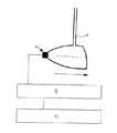
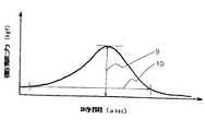
また、本発明では、ゴルフボールのドライバーでの最大衝撃力を1,100〜1,250kgfに限定している。本発明において、ドライバーの最大衝撃力とは、ゴルフボールをドライバーを取り付けたスイングロボットにてヘッドスピード40m/秒で打撃した時のボールとの衝突によって生じるヘッドの戻される力を衝撃力とし、図2のような装置により得られる衝撃力の経時変化を示すグラフ(図4)から、そのピーク値を最大衝撃力(9)としている。ドライバーでの最大衝撃力が1,100kgfより小さいと、フィーリングが軽すぎて打った感じがしない、即ち適度なソフトなフィーリングが得られない。1,250kgfより大きいと硬いフィーリングとなる。また、上記の衝撃力が発生してからなくなるまでの時間は、ボールがクラブのフェースに接触している時間、即ち接触時間(10)にあたる。接触時間としては、480〜580μsecが好ましい。接触時間が480μsecより短いと、球離れが速くコントロール性が低下する。580μsecより長くなると、ボールがクラブのフェースに引っ付き過ぎて重く感じる。
【0008】
更に、本発明ではパターでの最大衝撃力を40〜50kgfに限定している。本発明において、パターでの最大衝撃力とは、ゴルフボールをパターマシーン(振り子式)を用いて、パターを地面の垂直線から40°持ち上げて打撃した時のボールとの衝突によって生じるヘッドの戻される力を衝撃力とし、図3のような装置により得られる衝撃力の経時変化を示すグラフ(図4)から、そのピーク値を最大衝撃力(9)としている。パターでの最大衝撃力が40kgfより小さいと、フィーリングが軽すぎて打った感じがせず、50kgfより大きいと硬いフィーリングとなる。また、接触時間としては、730〜830μsecが好ましい。接触時間が730μsecより短いと、球離れが速すぎて、糸巻きゴルフボールのようなコントロール性が得られない。830μsecより長くなると、ボールがクラブのフェースに引っ付き過ぎて、引っかけ易くなる。
【0009】
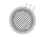
本発明のスリーピースソリッドゴルフボールを図1を参照して説明する。図1は本発明のスリーピースソリッドゴルフボールの断面概略図である。本発明のスリーピースソリッドゴルフボールでは、コア(1)上に中間層(2)を形成し、該中間層(2)上にカバー(3)を形成する。コア(1)は、基材ゴム、不飽和カルボン酸の金属塩、有機過酸化物、必要に応じて充填材、老化防止剤等を含有するゴム組成物を、通常のソリッドコアに用いられる方法、条件を用いて加熱圧縮加硫することにより得られる。基材ゴムとしては、従来からソリッドゴルフボールに用いられている天然ゴムおよび/または合成ゴムが用いられ、特にシス-1,4-結合少なくとも40%以上、好ましくは80%以上を有するいわゆるハイシスポリブタジエンゴムが好ましく、所望により、天然ゴム、ポリイソプレンゴム、スチレンポリブタジエンゴム、エチレン-プロピレン-ジエンゴム(EPDM)等を配合してもよい。
【0010】
不飽和カルボン酸の金属塩は、共架橋剤として作用し、特にアクリル酸またはメタクリル酸等のような炭素数3〜8のα,β-不飽和カルボン酸の、亜鉛、マグネシウム等の一価または二価の金属塩が挙げられるが、高い反発性を付与するアクリル酸亜鉛が好適である。配合量は基材ゴム100重量部に対して、15〜30重量部が好ましい。30重量部より多いと硬くなり過ぎてフィーリングが悪くなり、15重量部より少ないと反発が悪くなり飛距離が低下する。
【0011】
有機過酸化物は架橋剤または硬化剤として作用し、例えばジクミルパーオキサイドまたはt-ブチルパーオキサイドが挙げられ、ジクミルパーオキサイドが好適である。配合量は、基材ゴム100重量部に対して1.0〜3.0重量部が好ましい。1.0重量部未満では軟らかくなり過ぎて反発が悪くなり飛距離が低下する。3.0重量部を越えると硬くなり過ぎ、フィーリングが悪くなる。
【0012】
充填材は、ゴルフボールのコアに通常配合されるものであればよく、例えば無機塩(具体的には、酸化亜鉛、硫酸バリウム、炭酸カルシウム)、高比重金属粉末(例えば、タングステン粉末、モリブデン粉末等)およびそれらの混合物が挙げられる。配合量は、カバーおよびコアの比重、大きさに左右され限定的ではないが、基材ゴム100重量部に対して5〜50重量部であることが好ましい。5重量部未満ではコアが軽くなり過ぎてボールが軽くなり過ぎ、50重量部を越えるとコアが重くなり過ぎて、ボールが重くなり過ぎる。
【0013】
更に本発明のゴルフボールのコアには、老化防止剤またはしゃく解剤、その他ソリッドゴルフボールのコアの製造に通常使用し得る成分を適宜配合してもよい。尚、老化防止剤は0.2〜0.5重量部が好ましい。
【0014】
コア(1)は一般に、前述のゴム組成物を130〜180℃で10〜50分間加硫成形することにより得ることができる。本発明では、コアの直径は33〜37mm、好ましくは34〜36mmである。33mmより小さいと得られたボールが高スピン、低打出角となり、十分な飛距離が得られなくなる。37mmより大きいと中間層の厚さが薄くなり過ぎて打撃時のフィーリングが悪くなる。また、本発明の場合、コアは初期荷重10kgfを負荷した状態から終荷重130kgfを負荷したときまでの変形量が3.5〜4.5mm、好ましくは3.5〜4.0mmである。3.5mmより小さくなると得られたボールが硬くなり過ぎて高スピン、低打出角となり、飛距離が低下する。4.5より大きくなると得られたボールが軟らかくなり過ぎ、初速が不足して飛距離が低下する。
【0015】
本発明の中間層(2)は、特に限定されるものではないが、アイオノマー樹脂または熱可塑性エラストマー、若しくはそれらの混合物を主体とする材料で構成される。アイオノマー樹脂としては、エチレン-(メタ)アクリル酸の共重合体中のカルボン酸の一部を金属イオンで中和したものまたはその混合物が用いられ、中和する金属イオンとしては、1価または2価の金属イオン、例えばNaイオン、Kイオン、Liイオン、Znイオン、Caイオン、Mgイオンが挙げられる。上記アイオノマー樹脂の具体例としては、ハイミラン1605、1706(三井デュポンポリケミカル社製)、IOTEC 7010、8000(エクソン(Exxon)社製)等を例示することができる。熱可塑性エラストマーとしては、ポリウレタン系、ポリアミド系、ポリエステル系熱可塑性エラストマー、エポキシ基を含有するポリブタジエンブロックを有するスチレン-ブタジエン-スチレン構造のブロックポリマー、末端にOH基を付加した熱可塑性エラストマーが挙げられる。また中間層(2)用の組成物は、上記のアイオノマー樹脂または熱可塑性エラストマー、若しくはそれらの混合物を主体とする材料に加えて、充填材等の他の添加剤を含有してもよい。充填材としては、例えば無機塩(具体的には、酸化亜鉛、硫酸バリウム、炭酸カルシウム)、高比重金属粉末(例えば、タングステン粉末、モリブデン粉末等)およびそれらの混合物が挙げられる。
【0016】
本発明の中間層(2)は、ゴルフボールのカバーの形成に使用されている一般に公知の方法を用いて行うことができ、特に限定されるものではない。中間層用組成物を予め半球殻状のハーフシェルに成形し、それを2枚用いてソリッドコアを包み、加圧成形するか、または上記中間層用組成物を直接コア上に射出成形してコアを包み込む方法を用いてもよい。
【0017】
本発明では、中間層(2)は、ショアーD硬度30〜50、好ましくは30〜45を有する。ショアーD硬度が30より小さいと、ボール初速が小さくなり過ぎて十分な飛距離が得られない。ショアーD硬度が50より大きいと硬くなり過ぎて打撃時のフィーリングが悪くなる。更に、中間層(2)は厚さ0.5〜2.0mmを有することが好ましい。0.5mmより薄いと打撃時のフィーリングが硬くて悪くなり、2.0mmより厚いと、ボール初速が小さくなり過ぎて十分な飛距離が得られない。
【0018】
カバー(3)はソリッドゴルフボールのカバー材として通常使用されるエチレン-(メタ)アクリル酸の共重合体中のカルボン酸の一部を金属イオンで中和したアイオノマー樹脂、またはその混合物が用いられる。上記の中和する金属イオンとしては、アルカリ金属イオン、例えばNaイオン、Kイオン、Liイオン等;2価金属イオン、例えばZnイオン、Caイオン、Mgイオン等;3価金属イオン、例えばAlイオン、Ndイオン等;およびそれらの混合物が挙げられるが、Naイオン、Znイオン、Liイオン等が反発性、耐久性等からよく用いられる。アイオノマー樹脂の具体例としては、それだけに限定されないが、ハイミラン1557、1605、1652、1705、1706、1707、1855、1856(三井デュポンポリケミカル社製)、IOTEC 7010、8000(エクソン(Exxon)社製)等を例示することができる。
【0019】
また、本発明において、上記カバー用組成物には、主成分としての上記樹脂の他に必要に応じて、硫酸バリウム等の充填材や二酸化チタン等の着色剤や、その他の添加剤、例えば分散剤、老化防止剤、紫外線吸収剤、光安定剤並びに蛍光材料または蛍光増白剤等を、ゴルフボールカバーによる所望の特性が損なわれない範囲で含有していてもよいが、通常、着色剤の配合量はカバー樹脂100重量部に対して0.1〜0.5重量部が好ましい。
【0020】
カバー(3)を被覆する方法も上記中間層を被覆する方法と同様の方法が用いられ、こうして形成されるカバーは厚さ1.0〜4.0mmを有することが好ましい。1.0mmより薄いとボール初速が小さくなり過ぎて十分な飛距離が得られない。4.0mmより厚いと、得られたボールが硬くなり過ぎて打撃時フィーリングが悪くなる。また、カバー(3)はショアーD硬度62以上を有することが好ましい。カバー成形時、必要に応じて、ディンプルと呼ばれるくぼみを多数表面上に形成する。本発明のゴルフボールは美観を高め、商品価値を上げるために、通常ペイント仕上げ、マーキングスタンプ等を施されて市場に投入される。
【0021】
【実施例】
本発明を実施例により更に詳細に説明するが、本発明はこれら実施例に限定されるものではない。
【0022】
(実施例1〜5および比較例1〜2)
コアの作製
以下の表1(実施例)および表2(比較例)に示した配合のコア用ゴム組成物を混練ロールにより混練し、140℃×25分+165℃×8分間加熱プレスすることにより直径35.1mmのコアを得た。得られたコアの圧縮変形量を測定し、その結果を表3(実施例)および表4(比較例)に示した。試験方法は後記の通り行った。
【0023】
中間層の形成
以下の表1(実施例)および表2(比較例)に示す中間層用配合材料を、上記コア上に射出成形することにより厚さ1.6mmの中間層を形成した。得られた中間層のショアD硬度を表3(実施例)および表4(比較例)に示した。
【0024】
【表1】
【表2】
(注1) 日本合成ゴム(株)製のハイシスポリブタジエンゴム
(注2) 吉富製薬(株)製ヨシノックス425
(注3) 武田パーディシェウレタン工業(株)製のポリウレタン熱可塑性エラストマー
(注4) 武田パーディシェウレタン工業(株)製のポリウレタン熱可塑性エラストマー
(注5) 三井デュポンポリケミカル(株)製のナトリウムイオン中和エチレン-メタクリル酸共重合系アイオノマー樹脂
(注6) 三井デュポンポリケミカル(株)製の亜鉛イオン中和エチレン-メタクリル酸共重合体系アイオノマー樹脂
(注7) エクソンケミカル社製の亜鉛イオン中和エチレン-アクリル酸系アイオノマー樹脂
(注8) エクソンケミカル社製のナトリウムイオン中和エチレン-アクリル酸系アイオノマー樹脂
【0027】
カバーの形成
上記の表1および表2に示すカバー用組成物を、得られた中間層上に射出成形し、表面にペイントを塗装して、外径42.7mmを有するゴルフボールを得た。得られたゴルフボールの圧縮変形量、飛行性能として打出角、スピン量およびキャリー、ドライバーおよびパターでの最大衝撃力および接触時間、並びにドライバーおよびパターでの打撃時フィーリングを評価し、その結果を以下の表3(実施例)および表4(比較例)に示した。試験方法は後記の通り行った。
【0028】
(試験方法)
▲1▼圧縮変形量(コアおよびボール)
初期荷重10kgfを負荷した状態から終荷重130kgfを負荷したときまでの変形量を測定した。
▲2▼飛行性能
ツルーテンパー社製スイングロボットにウッド1番(W#1)クラブを取付け、ゴルフボールをヘッドスピード40m/秒で打撃し、打出角、スピン量、キャリー(落下点までの飛距離)を測定した。
▲3▼衝撃力
インパクト時のヘッドの戻りを加速度ピックアップにより加速度として測定し、
F(力)=m(ヘッド重量)×a(加速度)
の式に従ってヘッドが戻される力、即ち衝撃力を算出する。加速度ピックアップはBrueel & Kjaer社製のAcceler type4374を使用し、ドライバー(衝撃力測定用に加工された住友ゴム工業(株)製のDP-901)およびパター(衝撃力測定用に加工された住友ゴム工業(株)製のMAXFLI TM-8)ともにシャフト軸に垂直に、かつボール打点(フェース中心)の真裏に設置した。図2および図3にそれぞれ示すように、ドライバー(7)およびパター(8)に上記のように加速度ピックアップ(4)を取り付けて打撃し、チャージアンプ(5)で加速度を読み取り、デジタルオシロスコープ(6)により、衝撃力の経時変化を示す図4のようなグラフを得た。得られた曲線のピークでの衝撃力を最大衝撃力(9)とし、曲線の立ち上がりからベースラインに戻りきるまでの時間を、ボールがクラブのフェースに接触している時間、即ち接触時間(10)とする。チャージアンプはBrueel & Kjaer社製のcharge amplifier type2635、デジタルオシロスコープはIWATSU社製のDS6612を用いた。
(i) ドライバーを用いる場合、ゴルフボールをツルーテンパー社製スイングロボットにてヘッドスピード40m/秒で打撃した時の最大衝撃力および接触時間を測定し、
(ii)パターを用いる場合、パターマシーン(振り子式)においてパターを地面の垂直線から40°の角度まで持ち上げて振り下ろして打撃した時(ヘッドスピード2.9m/秒)の最大衝撃力および接触時間を測定した。
▲4▼フィーリング
10人のプロゴルファーによるドライバーおよびパターでの実打テストで評価した。判定基準は以下の通りとした。
判定基準
〇 …7人以上がソフトでコントロールし易く良好な打球感と答えた。
△ …7人以上が普通の打球感と答えた。
× …7人以上が硬い打球感と答えた。
【0029】
(試験結果)
【表3】
【表4】
** 市販のツーピースゴルフボール
【0031】
以上の結果より、本発明の実施例1〜5のゴルフボールは、従来の糸巻きゴルフボール(比較例3)と同様、ドライバーだけでなくパターでも優れた打撃時のフィーリングを維持しながら、従来のツーピースゴルフボール(比較例4)以上に飛行性能が向上した。それに対して、コアおよびボールの圧縮変形量が小さく、かつドライバーおよびパターでの最大衝撃力が大きい比較例1、およびコアおよびボールの圧縮変形量が小さく、かつパターでの最大衝撃力が大きい比較例2は、ドライバーおよびパターによる打撃時のフィーリングが硬くて悪く、飛行性能も実施例に劣る結果となった。
【0032】
【発明の効果】
本発明のスリーピースソリッドゴルフボールは、コアの直径および圧縮変形量、中間層のショアーD、ボールの圧縮変形量、ドライバーでの最大衝撃力およびパターでの最大衝撃力を特定範囲に規定することにより、従来の糸巻きゴルフボールと同様の優れた打撃時のフィーリングを有し、かつ飛行性能を向上させ得たものである。
【図面の簡単な説明】
【図1】 本発明のゴルフボールの断面概略図である。
【図2】 本発明のゴルフボールのドライバーでの衝撃力測定方法を示す概略図である。
【図3】 本発明のゴルフボールのパターでの衝撃力測定方法を示す概略図である。
【図4】 本発明のゴルフボールの衝撃力測定方法により得られる、衝撃力の経時変化を示すグラフ図である。
【符号の説明】
1 … コア
2 … 中間層
3 … カバー
4 … 加速度ピックアップ
5 … チャージアンプ
6 … デジタルオシロスコープ
7 … ドライバー
8 … パター
9 … 最大衝撃力
10 … 接触時間[0001]
BACKGROUND OF THE INVENTION
The present invention relates to a three-piece solid golf ball, and more particularly, to a three-piece solid golf ball having improved flight performance without impairing the feeling of excellent hitting.
[0002]
[Prior art]
The commercially available golf balls include solid golf balls such as two-piece golf balls and three-piece golf balls and thread wound golf balls. In recent years, two-piece golf balls and three-piece golf balls occupy most of the market because they can increase the flight distance while maintaining a soft feeling equivalent to that of a conventional wound golf ball. In addition, in the three-piece golf ball, there are provided golf balls that can obtain various hardness distributions as compared to the two-piece golf ball and that are excellent in feeling at the time of hitting without impairing the flight performance. However, even when the shot with the driver is soft, the feel when shot with the putter is harder than conventional thread-wound golf balls, and the ball is far away from the ball and difficult to control. ).
[0003]
[Problems to be solved by the invention]
The object of the present invention is to solve the problems of the conventional three-piece solid golf ball as described above, and to provide a golf ball with improved flight performance without impairing the feeling at the time of excellent hitting. .
[0004]
[Means for Solving the Problems]
As a result of intensive studies to achieve the above object, the present inventors have found that the core diameter and the amount of deformation from the initial load of 10 kgf to the final load of 130 kgf, the shore D of the intermediate layer, the ball By defining the above-mentioned deformation amount, maximum impact force by the driver, and maximum impact force by the putter within a specific range, it has the same excellent feel at the time of hitting as a conventional wound golf ball and improves the flight performance. The inventors have found that a golf ball can be obtained, and have completed the present invention.
[0005]
That is, the present invention provides a three-piece solid golf ball comprising a core (1), an intermediate layer (2) formed on the core, and a cover (3) covering the intermediate layer. It has a deformation amount of 3.5 to 4.5 mm from a state of 33 to 37 mm and an initial load of 10 kgf to a final load of 130 kgf, the intermediate layer (2) has a Shore D hardness of 30 to 50, and the golf The present invention relates to a three-piece solid golf ball characterized in that the ball has a deformation amount of 2.8 to 3.2 mm, a maximum impact force of 1,100 to 1,250 kgf with a driver, and a maximum impact force of 40 to 50 kgf with a putter.
[0006]
The three-piece solid golf ball of the present invention has a deformation amount of 2.8 to 3.2 mm, preferably 2.9 to 3.1, from a state where an initial load of 10 kgf is applied to when a final load of 130 kgf is applied. If it is smaller than 2.8 mm, the feeling, especially the feeling at the time of putting is hard, the ball separation is fast, and the controllability is deteriorated. If it is larger than 3.2 mm, the ball becomes too soft and the ball speed is lowered, so that a sufficient flight distance cannot be obtained.
[0007]
In the present invention, the maximum impact force of the golf ball driver is limited to 1,100 to 1,250 kgf. In the present invention, the maximum impact force of the driver is the force that returns the head caused by the collision with the ball when the golf ball is hit at a head speed of 40 m / sec by a swing robot with a driver attached. From the graph (FIG. 4) showing the change over time of the impact force obtained by the apparatus as shown in FIG. 2, the peak value is the maximum impact force (9). If the driver's maximum impact force is less than 1,100kgf, the feeling will be too light and you will not feel it hit, that is, you will not get a moderate soft feeling. If it is larger than 1,250kgf, it will have a hard feeling. Further, the time from when the impact force is generated until the impact force disappears corresponds to the time when the ball is in contact with the face of the club, that is, the contact time (10). The contact time is preferably 480 to 580 μsec. When the contact time is shorter than 480 μsec, the ball is separated quickly and the controllability is lowered. When it is longer than 580 μsec, the ball feels heavy because it is too stuck to the club face.
[0008]
Furthermore, in the present invention, the maximum impact force on the putter is limited to 40-50 kgf. In the present invention, the maximum impact force on the putter is the return of the head caused by the collision with the ball when the golf ball is hit with a putter machine (pendulum type) lifted by 40 ° from the vertical line of the ground. The peak force is defined as the maximum impact force (9) from the graph (FIG. 4) showing the change over time of the impact force obtained by the apparatus as shown in FIG. If the maximum impact force on the putter is less than 40 kgf, the feeling will be too light and you will not feel it hit, and if it is greater than 50 kgf, you will have a hard feeling. The contact time is preferably 730 to 830 μsec. When the contact time is shorter than 730 μsec, the ball separation is too fast, and the controllability like a wound golf ball cannot be obtained. If it is longer than 830 μsec, the ball is caught too much on the face of the club, and it becomes easy to catch.
[0009]
The three-piece solid golf ball of the present invention will be described with reference to FIG. FIG. 1 is a schematic cross-sectional view of a three-piece solid golf ball of the present invention. In the three-piece solid golf ball of the present invention, the intermediate layer (2) is formed on the core (1), and the cover (3) is formed on the intermediate layer (2). The core (1) is a method in which a rubber composition containing a base rubber, a metal salt of an unsaturated carboxylic acid, an organic peroxide, and optionally a filler, an anti-aging agent, etc. is used for a normal solid core. It is obtained by heat compression vulcanization using conditions. As the base rubber, natural rubber and / or synthetic rubber conventionally used for solid golf balls is used, and in particular, so-called high cis having at least 40% or more, preferably 80% or more of cis-1,4-bonds. Polybutadiene rubber is preferred, and if desired, natural rubber, polyisoprene rubber, styrene polybutadiene rubber, ethylene-propylene-diene rubber (EPDM) and the like may be blended.
[0010]
The metal salt of the unsaturated carboxylic acid acts as a co-crosslinking agent, and is particularly monovalent or zinc or magnesium of an α, β-unsaturated carboxylic acid having 3 to 8 carbon atoms such as acrylic acid or methacrylic acid. Although a divalent metal salt is mentioned, the zinc acrylate which provides high resilience is suitable. The blending amount is preferably 15 to 30 parts by weight with respect to 100 parts by weight of the base rubber. If it exceeds 30 parts by weight, it will become too hard and the feeling will be poor, and if it is less than 15 parts by weight, the rebound will be poor and the flight distance will be reduced.
[0011]
The organic peroxide acts as a crosslinking agent or a curing agent, and examples thereof include dicumyl peroxide and t-butyl peroxide, and dicumyl peroxide is preferable. The blending amount is preferably 1.0 to 3.0 parts by weight with respect to 100 parts by weight of the base rubber. If it is less than 1.0 part by weight, it will be too soft and the rebound will be worse and the flight distance will be reduced. If it exceeds 3.0 parts by weight, it becomes too hard and the feeling becomes worse.
[0012]
The filler is not particularly limited as long as it is usually blended in the core of the golf ball. For example, inorganic salts (specifically, zinc oxide, barium sulfate, calcium carbonate), high specific gravity metal powder (for example, tungsten powder, molybdenum powder). Etc.) and mixtures thereof. The blending amount is not limited depending on the specific gravity and size of the cover and the core, but is preferably 5 to 50 parts by weight with respect to 100 parts by weight of the base rubber. If it is less than 5 parts by weight, the core becomes too light and the ball becomes too light, and if it exceeds 50 parts by weight, the core becomes too heavy and the ball becomes too heavy.
[0013]
Further, the golf ball core of the present invention may be appropriately blended with an anti-aging agent, a peptizer, and other components that can be usually used for the production of a solid golf ball core. The anti-aging agent is preferably 0.2 to 0.5 parts by weight.
[0014]
The core (1) can be generally obtained by vulcanizing and molding the above rubber composition at 130 to 180 ° C. for 10 to 50 minutes. In the present invention, the diameter of the core is 33 to 37 mm, preferably 34 to 36 mm. If it is smaller than 33 mm, the resulting ball has a high spin and a low launch angle, and a sufficient flight distance cannot be obtained. If it is larger than 37 mm, the thickness of the intermediate layer becomes too thin and the feeling at the time of hitting becomes worse. In the present invention, the core has a deformation amount of 3.5 to 4.5 mm, preferably 3.5 to 4.0 mm, from a state in which an initial load of 10 kgf is applied to a case in which a final load of 130 kgf is applied. If it is smaller than 3.5 mm, the resulting ball becomes too hard, resulting in a high spin and a low launch angle, and the flight distance is reduced. If it exceeds 4.5, the resulting ball becomes too soft, the initial speed is insufficient, and the flight distance decreases.
[0015]
The intermediate layer (2) of the present invention is not particularly limited, but is composed of a material mainly composed of an ionomer resin, a thermoplastic elastomer, or a mixture thereof. As the ionomer resin, one obtained by neutralizing a part of carboxylic acid in a copolymer of ethylene- (meth) acrylic acid with a metal ion or a mixture thereof is used. Valent metal ions, such as Na ions, K ions, Li ions, Zn ions, Ca ions, and Mg ions. Specific examples of the ionomer resin include Himiran 1605 and 1706 (manufactured by Mitsui DuPont Polychemical Co.), IOTEC 7010 and 8000 (manufactured by Exxon), and the like. Examples of the thermoplastic elastomer include polyurethane-based, polyamide-based, polyester-based thermoplastic elastomers, block polymers having a styrene-butadiene-styrene structure having a polybutadiene block containing an epoxy group, and thermoplastic elastomers having an OH group added to the terminal. . Further, the composition for the intermediate layer (2) may contain other additives such as a filler in addition to the above-mentioned material mainly composed of an ionomer resin, a thermoplastic elastomer, or a mixture thereof. Examples of the filler include inorganic salts (specifically, zinc oxide, barium sulfate, calcium carbonate), high specific gravity metal powders (for example, tungsten powder, molybdenum powder, etc.), and mixtures thereof.
[0016]
The intermediate layer (2) of the present invention can be formed by a generally known method used for forming a golf ball cover, and is not particularly limited. The intermediate layer composition is pre-molded into a half-shell half shell, and the two are used to wrap the solid core and press mold, or the intermediate layer composition is directly injection molded onto the core. A method of wrapping the core may be used.
[0017]
In the present invention, the intermediate layer (2) has a Shore D hardness of 30 to 50, preferably 30 to 45. If the Shore D hardness is less than 30, the initial ball speed becomes too small to obtain a sufficient flight distance. If the Shore D hardness is greater than 50, it becomes too hard and the feeling at the time of hitting becomes worse. Further, the intermediate layer (2) preferably has a thickness of 0.5 to 2.0 mm. If it is thinner than 0.5 mm, the feeling at the time of hitting will be hard and worse, and if it is thicker than 2.0 mm, the initial velocity of the ball will be too small to obtain a sufficient flight distance.
[0018]
As the cover (3), an ionomer resin obtained by neutralizing a part of carboxylic acid in a copolymer of ethylene- (meth) acrylic acid usually used as a cover material for a solid golf ball with a metal ion, or a mixture thereof is used. . Examples of the metal ions to be neutralized include alkali metal ions such as Na ions, K ions and Li ions; divalent metal ions such as Zn ions, Ca ions and Mg ions; trivalent metal ions such as Al ions, Nd ions and the like; and mixtures thereof, Na ions, Zn ions, Li ions, etc. are often used from the viewpoint of resilience and durability. Specific examples of ionomer resins include, but are not limited to, High Milan 1557, 1605, 1562, 1705, 1706, 1707, 1855, 1856 (Mitsui DuPont Polychemical), IOTEC 7010, 8000 (Exxon) Etc. can be illustrated.
[0019]
Further, in the present invention, in addition to the resin as a main component, the cover composition may include a filler such as barium sulfate, a colorant such as titanium dioxide, and other additives such as a dispersion, as necessary. Agents, anti-aging agents, ultraviolet absorbers, light stabilizers and fluorescent materials or fluorescent brightening agents, etc. may be contained within the range in which the desired properties of the golf ball cover are not impaired. The blending amount is preferably 0.1 to 0.5 parts by weight with respect to 100 parts by weight of the cover resin.
[0020]
The method for covering the cover (3) is the same as the method for covering the intermediate layer, and the cover thus formed preferably has a thickness of 1.0 to 4.0 mm. If it is thinner than 1.0 mm, the initial ball speed becomes too small to obtain a sufficient flight distance. If it is thicker than 4.0 mm, the resulting ball will be too hard and the feeling at impact will be poor. The cover (3) preferably has a Shore D hardness of 62 or more. When forming the cover, if necessary, a number of dimples called dimples are formed on the surface. The golf ball of the present invention is usually put on the market with a paint finish, a marking stamp, etc. in order to enhance the beauty and increase the commercial value.
[0021]
【Example】
Examples The present invention will be described in more detail with reference to examples, but the present invention is not limited to these examples.
[0022]
(Examples 1-5 and Comparative Examples 1-2)
Core Preparation <br/> Table 1 (Examples) below and in Table 2 (Comparative Example) in the rubber composition for the core of the formulation shownin kneaded by a kneading roll, heated 140 ° C. × 25 minutes + 165 ° C. × 8 minutes A core with a diameter of 35.1 mm was obtained by pressing. The amount of compressive deformation of the obtained core was measured, and the results are shown in Table 3 (Example) and Table 4 (Comparative Example). The test method was performed as described later.
[0023]
Formation of intermediate layer An intermediate layer having a thickness of 1.6 mm is formed by injection molding the compounding materials for intermediate layer shown in Table 1 (Example) and Table 2 (Comparative Example) on the core. did. The Shore D hardness of the obtained intermediate layer is shown in Table 3 (Example) and Table 4 (Comparative Example).
[0024]
[Table 1]
[Table 2]
(Note 1) High-cis polybutadiene rubber manufactured by Nippon Synthetic Rubber Co., Ltd.
(Note 2) Yoshinox 425 manufactured by Yoshitomi Pharmaceutical Co., Ltd.
(Note 3) Polyurethane thermoplastic elastomer manufactured by Takeda Perdish Urethane Kogyo Co., Ltd.
(Note 4) Polyurethane thermoplastic elastomer manufactured by Takeda Perdiche Urethane Industry Co., Ltd.
(Note 5) Sodium ion neutralized ethylene-methacrylic acid copolymer ionomer resin manufactured by Mitsui DuPont Polychemical Co., Ltd.
(Note 6) Zinc ion neutralized ethylene-methacrylic acid copolymer ionomer resin manufactured by Mitsui DuPont Polychemical Co., Ltd.
(Note 7) Zinc ion neutralized ethylene-acrylic acid ionomer resin manufactured by Exxon Chemical
(Note 8) Sodium ion neutralized ethylene-acrylic acid ionomer resin manufactured by Exxon Chemical Co., Ltd. [0027]
Formation of cover A golf ball having an outer diameter of 42.7 mm is formed by injection-molding the cover composition shown in Tables 1 and 2 above onto the obtained intermediate layer and painting the surface thereof. Obtained. The golf ball was evaluated for compression deformation, flight performance, launch angle, spin rate and carry, maximum impact force and contact time with the driver and putter, and feeling when hit with the driver and putter. The results are shown in Table 3 (Examples) and Table 4 (Comparative Examples) below. The test method was performed as described later.
[0028]
(Test method)
(1) Compression deformation (core and ball)
The amount of deformation from the initial load of 10 kgf to the final load of 130 kgf was measured.
(2) Flight performance Mount a wood No. 1 (W # 1) club on a swing robot made by True Temper, hit a golf ball at a head speed of 40m / s, launch angle, spin rate, carry (flying distance to drop point) ) Was measured.
(3) The return of the head at the time of impact impact is measured as acceleration by an acceleration pickup,
F (force) = m (head weight) x a (acceleration)
The force for returning the head, that is, the impact force is calculated according to the following equation. Acceler pickup uses Acceler type 4374 manufactured by Brueel & Kjaer, and driver (DP-901 manufactured by Sumitomo Rubber Industries, Ltd. processed for impact force measurement) and putter (Sumitomo Rubber processed for impact force measurement) Both the MAXFLI TM-8 manufactured by Kogyo Co., Ltd. were installed perpendicular to the shaft axis and directly behind the ball hitting point (face center). As shown in FIGS. 2 and 3, the acceleration pickup (4) is attached to the driver (7) and the putter (8) as described above, and the acceleration is read by the charge amplifier (5). ), A graph as shown in FIG. 4 showing the change in impact force with time was obtained. The impact force at the peak of the obtained curve is the maximum impact force (9), and the time from the rise of the curve to the return to the baseline is the time that the ball is in contact with the club face, that is, the contact time (10 ). A charge amplifier type 2635 manufactured by Brueel & Kjaer was used as the charge amplifier, and a DS6612 manufactured by IWATSU was used as the digital oscilloscope.
(i) When using a driver, measure the maximum impact force and contact time when a golf ball is struck at a head speed of 40 m / sec with a swing robot manufactured by True Temper,
(ii) When using a putter, the maximum impact force and contact time when the putter is lifted and swung down to a 40 ° angle from the ground vertical line (head speed 2.9m / sec) on the putter machine (pendulum type) Was measured.
(4) Feeling
It was evaluated by a driver's and putter hit test with 10 professional golfers. The judgment criteria were as follows.
Judgment criteria 〇… 7 or more people answered that it was soft and easy to control and had a good shot feeling.
Δ: Seven or more people answered that they had a normal shot feeling.
× ... 7 or more responded with a hard shot feeling.
[0029]
(Test results)
[Table 3]
[Table 4]
** Commercially available two-piece golf ball [0031]
From the above results, the golf balls of Examples 1 to 5 of the present invention, as with the conventional thread-wound golf ball (Comparative Example 3), while maintaining excellent feeling during hitting not only with the driver but also with the putter, The flight performance was improved over that of the two-piece golf ball (Comparative Example 4). On the other hand, Comparative Example 1 in which the amount of compressive deformation of the core and the ball is small and the maximum impact force in the driver and the putter is large, and Comparison in which the amount of compressive deformation of the core and the ball is small and the maximum impact force in the putter is large In Example 2, the feeling of hitting with a driver and a putter was hard and bad, and the flight performance was inferior to that of the example.
[0032]
【The invention's effect】
The three-piece solid golf ball of the present invention has a specific range of core diameter and compression deformation, intermediate layer Shore D, ball compression deformation, maximum impact force with a driver and maximum impact force with a putter. The golf ball has excellent hitting feeling similar to that of a conventional wound golf ball, and has improved flight performance.
[Brief description of the drawings]
FIG. 1 is a schematic cross-sectional view of a golf ball of the present invention.
FIG. 2 is a schematic view showing a method of measuring an impact force with a golf ball driver of the present invention.
FIG. 3 is a schematic view showing a method for measuring an impact force with a putter of a golf ball of the present invention.
FIG. 4 is a graph showing the change with time of impact force obtained by the method for measuring impact force of a golf ball of the present invention.
[Explanation of symbols]
DESCRIPTION OF
10… contact time
Claims (4)
Translated fromJapanese該ゴルフボールがドライバーでの最大衝撃力1,100〜1,250kgfおよびパターでの最大衝撃力40〜50kgfを有し、
該ドライバーが住友ゴム工業(株)製のDP‐901であり、ドライバーでの打撃時のヘッドスピードが40m/秒であり、ドライバーでの打撃時のボールがクラブのフェースに接触している時間である接触時間が480〜580μsecであり、
該パターが住友ゴム工業(株)製のMAXFLI TM‐8であり、パターでの打撃時のヘッドスピードが2.9m/秒であり、パターでの打撃時の接触時間が730〜830μsecであり、
該中間層が、ポリウレタン系熱可塑性エラストマーから形成され、かつショアD硬度30〜50を有する
ことを特徴とするスリーピースソリッドゴルフボール。In a three-piece solid golf ball comprising a core (1), an intermediate layer (2) formed on the core, and a cover (3) covering the intermediate layer,
The golf ball has a maximum impact force of 1,100 to 1,250 kgf at the driver and a maximum impact force of 40 to 50 kgf at the putter,
The driver is DP-901 manufactured by Sumitomo Rubber Industries, and the head speed when hitting with the driver is 40 m / second, and the time when the ball hits with the driver is in contact with the face of the club. A certain contact time is 480 to 580 μsec,
Is a MAXFLI TM-8 of the putter is Sumitomo Rubber Industries Co., Ltd., head speed at the time of hitting with the putter is a 2.9m / sec, the contact time of when hit with a putter isRi 730~830μsec Der,
A three-piece solid golf ball, wherein the intermediate layer is formed of a polyurethane-based thermoplastic elastomer and has a Shore D hardness of 30 to 50 .
Priority Applications (6)
| Application Number | Priority Date | Filing Date | Title |
|---|---|---|---|
| JP26859897AJP4082765B2 (en) | 1997-10-01 | 1997-10-01 | Three-piece solid golf ball |
| AU86155/98AAU750804B2 (en) | 1997-10-01 | 1998-09-23 | Three piece solid golf ball |
| US09/159,678US6120391A (en) | 1997-10-01 | 1998-09-24 | Three piece solid golf ball |
| DE69833618TDE69833618D1 (en) | 1997-10-01 | 1998-09-29 | Three-piece, solid golf ball |
| EP98307947AEP0906775B1 (en) | 1997-10-01 | 1998-09-29 | Three piece solid golf ball |
| KR10-1998-0040941AKR100499987B1 (en) | 1997-10-01 | 1998-09-30 | Three piece solid golf ball |
Applications Claiming Priority (1)
| Application Number | Priority Date | Filing Date | Title |
|---|---|---|---|
| JP26859897AJP4082765B2 (en) | 1997-10-01 | 1997-10-01 | Three-piece solid golf ball |
Publications (2)
| Publication Number | Publication Date |
|---|---|
| JPH11104269A JPH11104269A (en) | 1999-04-20 |
| JP4082765B2true JP4082765B2 (en) | 2008-04-30 |
Family
ID=17460767
Family Applications (1)
| Application Number | Title | Priority Date | Filing Date |
|---|---|---|---|
| JP26859897AExpired - Fee RelatedJP4082765B2 (en) | 1997-10-01 | 1997-10-01 | Three-piece solid golf ball |
Country Status (6)
| Country | Link |
|---|---|
| US (1) | US6120391A (en) |
| EP (1) | EP0906775B1 (en) |
| JP (1) | JP4082765B2 (en) |
| KR (1) | KR100499987B1 (en) |
| AU (1) | AU750804B2 (en) |
| DE (1) | DE69833618D1 (en) |
Families Citing this family (15)
| Publication number | Priority date | Publication date | Assignee | Title |
|---|---|---|---|---|
| US6548618B2 (en)* | 1993-06-01 | 2003-04-15 | Spalding Sports Worldwide, Inc. | Golf ball having dual core and thin polyurethane cover formed by RIM |
| JP4082765B2 (en)* | 1997-10-01 | 2008-04-30 | Sriスポーツ株式会社 | Three-piece solid golf ball |
| JP4394790B2 (en) | 2000-02-08 | 2010-01-06 | Sriスポーツ株式会社 | Three-piece solid golf ball |
| JP2001252374A (en)* | 2000-03-09 | 2001-09-18 | Sumitomo Rubber Ind Ltd | Multipiece solid golf ball |
| KR100456392B1 (en)* | 2001-02-01 | 2004-11-10 | 미쓰이 가가쿠 가부시키가이샤 | Elastomeric composition for preparing olefinic elastomer crosslinked foam and use thereof |
| JP4708610B2 (en)* | 2001-07-06 | 2011-06-22 | Sriスポーツ株式会社 | Multi-piece solid golf ball |
| JP4873181B2 (en)* | 2007-11-19 | 2012-02-08 | ブリヂストンスポーツ株式会社 | Golf ball design method |
| PL2635903T3 (en)* | 2010-11-05 | 2019-02-28 | Moba Group B.V. | Method and apparatus for examining egg shells |
| US20130172105A1 (en)* | 2011-07-29 | 2013-07-04 | Nike, Inc. | Golf Ball Having Temperature Controllable Compression Deformation |
| US9089739B2 (en) | 2011-08-23 | 2015-07-28 | Nike, Inc. | Multi-core golf ball having increased initial velocity |
| US8979676B2 (en)* | 2011-08-23 | 2015-03-17 | Nike, Inc. | Multi-core golf ball having increased initial velocity at high swing speeds relative to low swing speeds |
| JP6440593B2 (en)* | 2015-08-07 | 2018-12-19 | 住友ゴム工業株式会社 | Golf ball |
| JP7703937B2 (en)* | 2021-07-29 | 2025-07-08 | ブリヂストンスポーツ株式会社 | Golf balls |
| JP7690814B2 (en)* | 2021-08-19 | 2025-06-11 | 住友ゴム工業株式会社 | Golf balls |
| JP7690815B2 (en)* | 2021-08-19 | 2025-06-11 | 住友ゴム工業株式会社 | Golf balls |
Family Cites Families (8)
| Publication number | Priority date | Publication date | Assignee | Title |
|---|---|---|---|---|
| JPH078301B2 (en)* | 1986-05-23 | 1995-02-01 | ブリヂストンスポーツ株式会社 | Solid Golf Ball |
| US5873796A (en)* | 1990-12-10 | 1999-02-23 | Acushnet Company | Multi-layer golf ball comprising a cover of ionomer blends |
| US5439227A (en)* | 1992-08-31 | 1995-08-08 | Bridgestone Sports Co., Ltd. | Multi-piece solid golf ball |
| JP2658811B2 (en)* | 1993-07-08 | 1997-09-30 | ブリヂストンスポーツ株式会社 | Three piece solid golf ball |
| US5688191A (en)* | 1995-06-07 | 1997-11-18 | Acushnet Company | Multilayer golf ball |
| US6042488A (en)* | 1995-06-15 | 2000-03-28 | Spalding Sports Worldwide, Inc. | Multi-layer golf ball and method of making same |
| JP2924720B2 (en)* | 1995-06-23 | 1999-07-26 | ブリヂストンスポーツ株式会社 | Three piece solid golf ball |
| JP4082765B2 (en)* | 1997-10-01 | 2008-04-30 | Sriスポーツ株式会社 | Three-piece solid golf ball |
- 1997
- 1997-10-01JPJP26859897Apatent/JP4082765B2/ennot_activeExpired - Fee Related
- 1998
- 1998-09-23AUAU86155/98Apatent/AU750804B2/ennot_activeCeased
- 1998-09-24USUS09/159,678patent/US6120391A/ennot_activeExpired - Lifetime
- 1998-09-29EPEP98307947Apatent/EP0906775B1/ennot_activeExpired - Lifetime
- 1998-09-29DEDE69833618Tpatent/DE69833618D1/ennot_activeExpired - Lifetime
- 1998-09-30KRKR10-1998-0040941Apatent/KR100499987B1/ennot_activeExpired - Fee Related
Also Published As
| Publication number | Publication date |
|---|---|
| AU750804B2 (en) | 2002-07-25 |
| US6120391A (en) | 2000-09-19 |
| KR19990036728A (en) | 1999-05-25 |
| DE69833618D1 (en) | 2006-04-27 |
| EP0906775A1 (en) | 1999-04-07 |
| AU8615598A (en) | 1999-04-22 |
| JPH11104269A (en) | 1999-04-20 |
| KR100499987B1 (en) | 2005-09-26 |
| EP0906775B1 (en) | 2006-03-01 |
Similar Documents
| Publication | Publication Date | Title |
|---|---|---|
| JP3731946B2 (en) | Three-piece solid golf ball | |
| US6319154B1 (en) | Solid golf ball having defined hardness profile | |
| US6494794B1 (en) | Two-piece solid golf ball | |
| JP3534325B2 (en) | Golf ball | |
| JP3067611B2 (en) | Two-piece solid golf ball | |
| JP3658210B2 (en) | Multi-piece solid golf ball | |
| JPH09215774A (en) | Two-piece solid golf ball | |
| JP4082765B2 (en) | Three-piece solid golf ball | |
| JPH07194734A (en) | Three-pieces solid golf ball | |
| JP3401411B2 (en) | Solid golf ball | |
| US7101292B2 (en) | Multi-piece solid golf ball | |
| US6692381B2 (en) | Solid golf ball | |
| US20020045500A1 (en) | Light weight golf ball | |
| US20030064828A1 (en) | Three-piece solid golf ball | |
| US6616548B2 (en) | Two-piece solid golf ball | |
| US6838524B2 (en) | Solid golf ball | |
| JPH08164226A (en) | Golf ball | |
| US20020086742A1 (en) | Solid golf ball | |
| US6787609B2 (en) | Solid golf ball | |
| US20030211902A1 (en) | Three-piece solid golf ball | |
| JP2611653B2 (en) | Golf ball | |
| JP2003079765A (en) | Golf ball | |
| JP3086429B2 (en) | Solid golf ball | |
| US6716115B2 (en) | Thread wound golf ball | |
| JP3905593B2 (en) | Hollow solid golf ball |
Legal Events
| Date | Code | Title | Description |
|---|---|---|---|
| A621 | Written request for application examination | Free format text:JAPANESE INTERMEDIATE CODE: A621 Effective date:20040607 | |
| A711 | Notification of change in applicant | Free format text:JAPANESE INTERMEDIATE CODE: A711 Effective date:20050518 | |
| A521 | Request for written amendment filed | Free format text:JAPANESE INTERMEDIATE CODE: A821 Effective date:20050728 | |
| RD02 | Notification of acceptance of power of attorney | Free format text:JAPANESE INTERMEDIATE CODE: A7422 Effective date:20050728 | |
| A131 | Notification of reasons for refusal | Free format text:JAPANESE INTERMEDIATE CODE: A131 Effective date:20061219 | |
| A521 | Request for written amendment filed | Free format text:JAPANESE INTERMEDIATE CODE: A523 Effective date:20070215 | |
| A02 | Decision of refusal | Free format text:JAPANESE INTERMEDIATE CODE: A02 Effective date:20070911 | |
| A521 | Request for written amendment filed | Free format text:JAPANESE INTERMEDIATE CODE: A523 Effective date:20071011 | |
| A911 | Transfer to examiner for re-examination before appeal (zenchi) | Free format text:JAPANESE INTERMEDIATE CODE: A911 Effective date:20071221 | |
| TRDD | Decision of grant or rejection written | ||
| A01 | Written decision to grant a patent or to grant a registration (utility model) | Free format text:JAPANESE INTERMEDIATE CODE: A01 Effective date:20080205 | |
| A61 | First payment of annual fees (during grant procedure) | Free format text:JAPANESE INTERMEDIATE CODE: A61 Effective date:20080212 | |
| R150 | Certificate of patent or registration of utility model | Free format text:JAPANESE INTERMEDIATE CODE: R150 | |
| FPAY | Renewal fee payment (event date is renewal date of database) | Free format text:PAYMENT UNTIL: 20110222 Year of fee payment:3 | |
| FPAY | Renewal fee payment (event date is renewal date of database) | Free format text:PAYMENT UNTIL: 20120222 Year of fee payment:4 | |
| FPAY | Renewal fee payment (event date is renewal date of database) | Free format text:PAYMENT UNTIL: 20120222 Year of fee payment:4 | |
| FPAY | Renewal fee payment (event date is renewal date of database) | Free format text:PAYMENT UNTIL: 20130222 Year of fee payment:5 | |
| FPAY | Renewal fee payment (event date is renewal date of database) | Free format text:PAYMENT UNTIL: 20140222 Year of fee payment:6 | |
| R250 | Receipt of annual fees | Free format text:JAPANESE INTERMEDIATE CODE: R250 | |
| R250 | Receipt of annual fees | Free format text:JAPANESE INTERMEDIATE CODE: R250 | |
| LAPS | Cancellation because of no payment of annual fees |