JP4082372B2 - Fiber optic cable - Google Patents
Fiber optic cableDownload PDFInfo
- Publication number
- JP4082372B2 JP4082372B2JP2004094047AJP2004094047AJP4082372B2JP 4082372 B2JP4082372 B2JP 4082372B2JP 2004094047 AJP2004094047 AJP 2004094047AJP 2004094047 AJP2004094047 AJP 2004094047AJP 4082372 B2JP4082372 B2JP 4082372B2
- Authority
- JP
- Japan
- Prior art keywords
- optical fiber
- glass fiber
- resin
- fiber cable
- epoxy resin
- Prior art date
- Legal status (The legal status is an assumption and is not a legal conclusion. Google has not performed a legal analysis and makes no representation as to the accuracy of the status listed.)
- Expired - Fee Related
Links
- 239000000835fiberSubstances0.000titleclaimsdescription8
- 229920005989resinPolymers0.000claimsdescription139
- 239000011347resinSubstances0.000claimsdescription139
- 239000003365glass fiberSubstances0.000claimsdescription138
- 239000013307optical fiberSubstances0.000claimsdescription108
- 239000011159matrix materialSubstances0.000claimsdescription61
- 239000000463materialSubstances0.000claimsdescription41
- 238000005452bendingMethods0.000claimsdescription32
- 239000004850liquid epoxy resins (LERs)Substances0.000claimsdescription29
- 150000008065acid anhydridesChemical class0.000claimsdescription20
- 239000002685polymerization catalystSubstances0.000claimsdescription15
- 239000003822epoxy resinSubstances0.000description52
- 229920000647polyepoxidePolymers0.000description52
- 239000011342resin compositionSubstances0.000description43
- IISBACLAFKSPIT-UHFFFAOYSA-Nbisphenol AChemical compoundC=1C=C(O)C=CC=1C(C)(C)C1=CC=C(O)C=C1IISBACLAFKSPIT-UHFFFAOYSA-N0.000description27
- 239000000126substanceSubstances0.000description19
- 238000010538cationic polymerization reactionMethods0.000description15
- 238000002156mixingMethods0.000description15
- 239000003795chemical substances by applicationSubstances0.000description13
- -1for examplePolymers0.000description11
- 239000011521glassSubstances0.000description10
- 238000005470impregnationMethods0.000description9
- 239000000203mixtureSubstances0.000description9
- 229920005992thermoplastic resinPolymers0.000description9
- ATUOYWHBWRKTHZ-UHFFFAOYSA-NPropaneChemical compoundCCCATUOYWHBWRKTHZ-UHFFFAOYSA-N0.000description8
- 229920001567vinyl ester resinPolymers0.000description8
- 230000000052comparative effectEffects0.000description7
- 150000002148estersChemical class0.000description7
- 238000004519manufacturing processMethods0.000description7
- VNWKTOKETHGBQD-UHFFFAOYSA-NmethaneChemical compoundCVNWKTOKETHGBQD-UHFFFAOYSA-N0.000description7
- RTZKZFJDLAIYFH-UHFFFAOYSA-NDiethyl etherChemical compoundCCOCCRTZKZFJDLAIYFH-UHFFFAOYSA-N0.000description6
- XYFCBTPGUUZFHI-UHFFFAOYSA-NPhosphineChemical compoundPXYFCBTPGUUZFHI-UHFFFAOYSA-N0.000description6
- 229910000831SteelInorganic materials0.000description5
- 239000003085diluting agentSubstances0.000description5
- 238000010438heat treatmentMethods0.000description5
- 229920003986novolacPolymers0.000description5
- 229920000098polyolefinPolymers0.000description5
- 239000010959steelSubstances0.000description5
- 238000004804windingMethods0.000description5
- RWSOTUBLDIXVET-UHFFFAOYSA-NDihydrogen sulfideChemical classSRWSOTUBLDIXVET-UHFFFAOYSA-N0.000description4
- PPBRXRYQALVLMV-UHFFFAOYSA-NStyreneChemical compoundC=CC1=CC=CC=C1PPBRXRYQALVLMV-UHFFFAOYSA-N0.000description4
- 239000002253acidSubstances0.000description4
- 229920006231aramid fiberPolymers0.000description4
- ZWAJLVLEBYIOTI-UHFFFAOYSA-Ncyclohexene oxideChemical groupC1CCCC2OC21ZWAJLVLEBYIOTI-UHFFFAOYSA-N0.000description4
- VURFVHCLMJOLKN-UHFFFAOYSA-NdiphosphaneChemical compoundPPVURFVHCLMJOLKN-UHFFFAOYSA-N0.000description4
- 230000000704physical effectEffects0.000description4
- 239000007787solidSubstances0.000description4
- LTVUCOSIZFEASK-MPXCPUAZSA-N(3ar,4s,7r,7as)-3a-methyl-3a,4,7,7a-tetrahydro-4,7-methano-2-benzofuran-1,3-dioneChemical compoundC([C@H]1C=C2)[C@H]2[C@H]2[C@]1(C)C(=O)OC2=OLTVUCOSIZFEASK-MPXCPUAZSA-N0.000description3
- 1250000040086 membered carbocyclic groupChemical group0.000description3
- XOIZUVFIXICDDB-UHFFFAOYSA-N6-methyl-4-(2-methyloxiran-2-yl)-7-oxabicyclo[4.1.0]heptaneChemical compoundC1CC2OC2(C)CC1C1(C)CO1XOIZUVFIXICDDB-UHFFFAOYSA-N0.000description3
- 229910018072Al 2 O 3Inorganic materials0.000description3
- 239000004593EpoxySubstances0.000description3
- 229920013646HycarPolymers0.000description3
- 229910004298SiO 2Inorganic materials0.000description3
- 229920003232aliphatic polyesterPolymers0.000description3
- 125000004432carbon atomChemical groupC*0.000description3
- 238000005253claddingMethods0.000description3
- 125000001997phenyl groupChemical group[H]C1=C([H])C([H])=C(*)C([H])=C1[H]0.000description3
- 150000004714phosphonium saltsChemical class0.000description3
- 229920001296polysiloxanePolymers0.000description3
- 150000003839saltsChemical class0.000description3
- SSUJUUNLZQVZMO-UHFFFAOYSA-N1,2,3,4,8,9,10,10a-octahydropyrimido[1,2-a]azepineChemical compoundC1CCC=CN2CCCNC21SSUJUUNLZQVZMO-UHFFFAOYSA-N0.000description2
- SOFKFQGOGQABAE-UHFFFAOYSA-N1,3,5-tris[(dimethylamino)methyl]cyclohexa-2,4-dien-1-olChemical compoundCN(C)CC1=CC(CN(C)C)=CC(O)(CN(C)C)C1SOFKFQGOGQABAE-UHFFFAOYSA-N0.000description2
- LVEYOSJUKRVCCF-UHFFFAOYSA-N1,3-bis(diphenylphosphino)propaneChemical compoundC=1C=CC=CC=1P(C=1C=CC=CC=1)CCCP(C=1C=CC=CC=1)C1=CC=CC=C1LVEYOSJUKRVCCF-UHFFFAOYSA-N0.000description2
- DCTOHCCUXLBQMS-UHFFFAOYSA-N1-undeceneChemical compoundCCCCCCCCCC=CDCTOHCCUXLBQMS-UHFFFAOYSA-N0.000description2
- HECLRDQVFMWTQS-RGOKHQFPSA-N1755-01-7Chemical compoundC1[C@H]2[C@@H]3CC=C[C@@H]3[C@@H]1C=C2HECLRDQVFMWTQS-RGOKHQFPSA-N0.000description2
- HRKGITNCAYZTAU-UHFFFAOYSA-N2-(propoxymethyl)-7-oxabicyclo[4.1.0]heptaneChemical compoundC(CC)OCC1C2C(CCC1)O2HRKGITNCAYZTAU-UHFFFAOYSA-N0.000description2
- LXBGSDVWAMZHDD-UHFFFAOYSA-N2-methyl-1h-imidazoleChemical compoundCC1=NC=CN1LXBGSDVWAMZHDD-UHFFFAOYSA-N0.000description2
- GRLCAHRUZPOHEH-UHFFFAOYSA-N5-propoxy-7-oxabicyclo[4.1.0]hepta-1(6),2,4-trieneChemical compoundCCCOC1=CC=CC2=C1O2GRLCAHRUZPOHEH-UHFFFAOYSA-N0.000description2
- MWSKJDNQKGCKPA-UHFFFAOYSA-N6-methyl-3a,4,5,7a-tetrahydro-2-benzofuran-1,3-dioneChemical compoundC1CC(C)=CC2C(=O)OC(=O)C12MWSKJDNQKGCKPA-UHFFFAOYSA-N0.000description2
- 229930185605BisphenolNatural products0.000description2
- 229920002121Hydroxyl-terminated polybutadienePolymers0.000description2
- 208000019651NDE1-related microhydranencephalyDiseases0.000description2
- 239000004952PolyamideSubstances0.000description2
- 125000002947alkylene groupChemical group0.000description2
- XUCHXOAWJMEFLF-UHFFFAOYSA-Nbisphenol F diglycidyl etherChemical compoundC1OC1COC(C=C1)=CC=C1CC(C=C1)=CC=C1OCC1CO1XUCHXOAWJMEFLF-UHFFFAOYSA-N0.000description2
- 229910052796boronInorganic materials0.000description2
- 239000003054catalystSubstances0.000description2
- 238000000576coating methodMethods0.000description2
- GYZLOYUZLJXAJU-UHFFFAOYSA-Ndiglycidyl etherChemical compoundC1OC1COCC1CO1GYZLOYUZLJXAJU-UHFFFAOYSA-N0.000description2
- 239000004205dimethyl polysiloxaneSubstances0.000description2
- 235000013870dimethyl polysiloxaneNutrition0.000description2
- 125000003700epoxy groupChemical group0.000description2
- 239000007789gasSubstances0.000description2
- 125000003055glycidyl groupChemical groupC(C1CO1)*0.000description2
- 150000004820halidesChemical class0.000description2
- 239000004615ingredientSubstances0.000description2
- ZFSLODLOARCGLH-UHFFFAOYSA-Nisocyanuric acidChemical compoundOC1=NC(O)=NC(O)=N1ZFSLODLOARCGLH-UHFFFAOYSA-N0.000description2
- 238000000034methodMethods0.000description2
- VYKXQOYUCMREIS-UHFFFAOYSA-Nmethylhexahydrophthalic anhydrideChemical compoundC1CCCC2C(=O)OC(=O)C21CVYKXQOYUCMREIS-UHFFFAOYSA-N0.000description2
- 239000003094microcapsuleSubstances0.000description2
- WWZKQHOCKIZLMA-UHFFFAOYSA-Noctanoic acidChemical compoundCCCCCCCC(O)=OWWZKQHOCKIZLMA-UHFFFAOYSA-N0.000description2
- 125000002524organometallic groupChemical group0.000description2
- 230000002093peripheral effectEffects0.000description2
- 229910000073phosphorus hydrideInorganic materials0.000description2
- 229920000435poly(dimethylsiloxane)Polymers0.000description2
- 229920002647polyamidePolymers0.000description2
- 229920000728polyesterPolymers0.000description2
- 239000004848polyfunctional curativeSubstances0.000description2
- 238000012805post-processingMethods0.000description2
- 239000001294propaneSubstances0.000description2
- 238000012360testing methodMethods0.000description2
- RIOQSEWOXXDEQQ-UHFFFAOYSA-NtriphenylphosphineChemical compoundC1=CC=CC=C1P(C=1C=CC=CC=1)C1=CC=CC=C1RIOQSEWOXXDEQQ-UHFFFAOYSA-N0.000description2
- KYLUAQBYONVMCP-UHFFFAOYSA-N(2-methylphenyl)phosphaneChemical compoundCC1=CC=CC=C1PKYLUAQBYONVMCP-UHFFFAOYSA-N0.000description1
- RUEBPOOTFCZRBC-UHFFFAOYSA-N(5-methyl-2-phenyl-1h-imidazol-4-yl)methanolChemical compoundOCC1=C(C)NC(C=2C=CC=CC=2)=N1RUEBPOOTFCZRBC-UHFFFAOYSA-N0.000description1
- XGCDBGRZEKYHNV-UHFFFAOYSA-N1,1-bis(diphenylphosphino)methaneChemical compoundC=1C=CC=CC=1P(C=1C=CC=CC=1)CP(C=1C=CC=CC=1)C1=CC=CC=C1XGCDBGRZEKYHNV-UHFFFAOYSA-N0.000description1
- QFMZQPDHXULLKC-UHFFFAOYSA-N1,2-bis(diphenylphosphino)ethaneChemical compoundC=1C=CC=CC=1P(C=1C=CC=CC=1)CCP(C=1C=CC=CC=1)C1=CC=CC=C1QFMZQPDHXULLKC-UHFFFAOYSA-N0.000description1
- GIWQSPITLQVMSG-UHFFFAOYSA-N1,2-dimethylimidazoleChemical compoundCC1=NC=CN1CGIWQSPITLQVMSG-UHFFFAOYSA-N0.000description1
- FBHPRUXJQNWTEW-UHFFFAOYSA-N1-benzyl-2-methylimidazoleChemical compoundCC1=NC=CN1CC1=CC=CC=C1FBHPRUXJQNWTEW-UHFFFAOYSA-N0.000description1
- MCTWTZJPVLRJOU-UHFFFAOYSA-N1-methyl-1H-imidazoleChemical compoundCN1C=CN=C1MCTWTZJPVLRJOU-UHFFFAOYSA-N0.000description1
- SEULWJSKCVACTH-UHFFFAOYSA-N1-phenylimidazoleChemical compoundC1=NC=CN1C1=CC=CC=C1SEULWJSKCVACTH-UHFFFAOYSA-N0.000description1
- RNFJDJUURJAICM-UHFFFAOYSA-N2,2,4,4,6,6-hexaphenoxy-1,3,5-triaza-2$l^{5},4$l^{5},6$l^{5}-triphosphacyclohexa-1,3,5-trieneChemical compoundN=1P(OC=2C=CC=CC=2)(OC=2C=CC=CC=2)=NP(OC=2C=CC=CC=2)(OC=2C=CC=CC=2)=NP=1(OC=1C=CC=CC=1)OC1=CC=CC=C1RNFJDJUURJAICM-UHFFFAOYSA-N0.000description1
- RMXNWSLMRYWWMS-UHFFFAOYSA-N2-(7-oxabicyclo[4.1.0]hepta-1,3,5-trien-2-yl)-5-propoxy-7-oxabicyclo[4.1.0]hepta-1,3,5-trieneChemical groupC(CC)OC1=C2C(=C(C=C1)C1=C3C(=CC=C1)O3)O2RMXNWSLMRYWWMS-UHFFFAOYSA-N0.000description1
- BXGYYDRIMBPOMN-UHFFFAOYSA-N2-(hydroxymethoxy)ethoxymethanolChemical compoundOCOCCOCOBXGYYDRIMBPOMN-UHFFFAOYSA-N0.000description1
- OBETXYAYXDNJHR-UHFFFAOYSA-N2-Ethylhexanoic acidChemical compoundCCCCC(CC)C(O)=OOBETXYAYXDNJHR-UHFFFAOYSA-N0.000description1
- YTWBFUCJVWKCCK-UHFFFAOYSA-N2-heptadecyl-1h-imidazoleChemical compoundCCCCCCCCCCCCCCCCCC1=NC=CN1YTWBFUCJVWKCCK-UHFFFAOYSA-N0.000description1
- WFUGQJXVXHBTEM-UHFFFAOYSA-N2-hydroperoxy-2-(2-hydroperoxybutan-2-ylperoxy)butaneChemical compoundCCC(C)(OO)OOC(C)(CC)OOWFUGQJXVXHBTEM-UHFFFAOYSA-N0.000description1
- QXSNXUCNBZLVFM-UHFFFAOYSA-N2-methyl-1h-imidazole;1,3,5-triazinane-2,4,6-trioneChemical compoundCC1=NC=CN1.O=C1NC(=O)NC(=O)N1QXSNXUCNBZLVFM-UHFFFAOYSA-N0.000description1
- RJIQELZAIWFNTQ-UHFFFAOYSA-N2-phenyl-1h-imidazole;1,3,5-triazinane-2,4,6-trioneChemical compoundO=C1NC(=O)NC(=O)N1.C1=CNC(C=2C=CC=CC=2)=N1RJIQELZAIWFNTQ-UHFFFAOYSA-N0.000description1
- LLEASVZEQBICSN-UHFFFAOYSA-N2-undecyl-1h-imidazoleChemical compoundCCCCCCCCCCCC1=NC=CN1LLEASVZEQBICSN-UHFFFAOYSA-N0.000description1
- UIDDPPKZYZTEGS-UHFFFAOYSA-N3-(2-ethyl-4-methylimidazol-1-yl)propanenitrileChemical compoundCCC1=NC(C)=CN1CCC#NUIDDPPKZYZTEGS-UHFFFAOYSA-N0.000description1
- SESYNEDUKZDRJL-UHFFFAOYSA-N3-(2-methylimidazol-1-yl)propanenitrileChemical compoundCC1=NC=CN1CCC#NSESYNEDUKZDRJL-UHFFFAOYSA-N0.000description1
- BVYPJEBKDLFIDL-UHFFFAOYSA-N3-(2-phenylimidazol-1-yl)propanenitrileChemical compoundN#CCCN1C=CN=C1C1=CC=CC=C1BVYPJEBKDLFIDL-UHFFFAOYSA-N0.000description1
- SZUPZARBRLCVCB-UHFFFAOYSA-N3-(2-undecylimidazol-1-yl)propanenitrileChemical compoundCCCCCCCCCCCC1=NC=CN1CCC#NSZUPZARBRLCVCB-UHFFFAOYSA-N0.000description1
- LYZFSSDDDMVLSX-UHFFFAOYSA-N4-(2-aminoethyl)-6-(2-undecyl-1H-imidazol-5-yl)-1,3,5-triazin-2-amineChemical compoundNCCC1=NC(=NC(=N1)N)C=1N=C(NC1)CCCCCCCCCCCLYZFSSDDDMVLSX-UHFFFAOYSA-N0.000description1
- BCJVBDBJSMFBRW-UHFFFAOYSA-N4-diphenylphosphanylbutyl(diphenyl)phosphaneChemical compoundC=1C=CC=CC=1P(C=1C=CC=CC=1)CCCCP(C=1C=CC=CC=1)C1=CC=CC=C1BCJVBDBJSMFBRW-UHFFFAOYSA-N0.000description1
- 1250000010545 membered carbocyclic groupChemical group0.000description1
- MZFPAWGWFDGCHP-UHFFFAOYSA-N5-diphenylphosphanylpentyl(diphenyl)phosphaneChemical compoundC=1C=CC=CC=1P(C=1C=CC=CC=1)CCCCCP(C=1C=CC=CC=1)C1=CC=CC=C1MZFPAWGWFDGCHP-UHFFFAOYSA-N0.000description1
- TYOXIFXYEIILLY-UHFFFAOYSA-N5-methyl-2-phenyl-1h-imidazoleChemical compoundN1C(C)=CN=C1C1=CC=CC=C1TYOXIFXYEIILLY-UHFFFAOYSA-N0.000description1
- ULKLGIFJWFIQFF-UHFFFAOYSA-N5K8XI641G3Chemical compoundCCC1=NC=C(C)N1ULKLGIFJWFIQFF-UHFFFAOYSA-N0.000description1
- LCFVJGUPQDGYKZ-UHFFFAOYSA-NBisphenol A diglycidyl etherChemical classC=1C=C(OCC2OC2)C=CC=1C(C)(C)C(C=C1)=CC=C1OCC1CO1LCFVJGUPQDGYKZ-UHFFFAOYSA-N0.000description1
- OKTJSMMVPCPJKN-UHFFFAOYSA-NCarbonChemical group[C]OKTJSMMVPCPJKN-UHFFFAOYSA-N0.000description1
- UFHFLCQGNIYNRP-UHFFFAOYSA-NHydrogenChemical compound[H][H]UFHFLCQGNIYNRP-UHFFFAOYSA-N0.000description1
- 239000004698PolyethyleneSubstances0.000description1
- GOOHAUXETOMSMM-UHFFFAOYSA-NPropylene oxideChemical classCC1CO1GOOHAUXETOMSMM-UHFFFAOYSA-N0.000description1
- BLRPTPMANUNPDV-UHFFFAOYSA-NSilaneChemical compound[SiH4]BLRPTPMANUNPDV-UHFFFAOYSA-N0.000description1
- UUQQGGWZVKUCBD-UHFFFAOYSA-N[4-(hydroxymethyl)-2-phenyl-1h-imidazol-5-yl]methanolChemical compoundN1C(CO)=C(CO)N=C1C1=CC=CC=C1UUQQGGWZVKUCBD-UHFFFAOYSA-N0.000description1
- 125000004018acid anhydride groupChemical group0.000description1
- 239000000853adhesiveSubstances0.000description1
- 230000001070adhesive effectEffects0.000description1
- 230000002411adverseEffects0.000description1
- 239000002518antifoaming agentSubstances0.000description1
- 229910052787antimonyInorganic materials0.000description1
- WATWJIUSRGPENY-UHFFFAOYSA-Nantimony atomChemical compound[Sb]WATWJIUSRGPENY-UHFFFAOYSA-N0.000description1
- 150000001642boronic acid derivativesChemical class0.000description1
- SHZIWNPUGXLXDT-UHFFFAOYSA-Ncaproic acid ethyl esterNatural productsCCCCCC(=O)OCCSHZIWNPUGXLXDT-UHFFFAOYSA-N0.000description1
- 125000002091cationic groupChemical group0.000description1
- 238000006243chemical reactionMethods0.000description1
- 239000011248coating agentSubstances0.000description1
- 238000013329compoundingMethods0.000description1
- 150000001875compoundsChemical class0.000description1
- 229920001577copolymerPolymers0.000description1
- 230000001186cumulative effectEffects0.000description1
- 125000000113cyclohexyl groupChemical group[H]C1([H])C([H])([H])C([H])([H])C([H])(*)C([H])([H])C1([H])[H]0.000description1
- ZXKWUYWWVSKKQZ-UHFFFAOYSA-Ncyclohexyl(diphenyl)phosphaneChemical compoundC1CCCCC1P(C=1C=CC=CC=1)C1=CC=CC=C1ZXKWUYWWVSKKQZ-UHFFFAOYSA-N0.000description1
- 230000002542deteriorative effectEffects0.000description1
- VPLLTGLLUHLIHA-UHFFFAOYSA-Ndicyclohexyl(phenyl)phosphaneChemical compoundC1CCCCC1P(C=1C=CC=CC=1)C1CCCCC1VPLLTGLLUHLIHA-UHFFFAOYSA-N0.000description1
- 238000009826distributionMethods0.000description1
- 230000000694effectsEffects0.000description1
- 239000002320enamel (paints)Substances0.000description1
- 239000010419fine particleSubstances0.000description1
- 239000003063flame retardantSubstances0.000description1
- 238000009472formulationMethods0.000description1
- 229940085942formulation rDrugs0.000description1
- 238000012812general testMethods0.000description1
- LNEPOXFFQSENCJ-UHFFFAOYSA-NhaloperidolChemical compoundC1CC(O)(C=2C=CC(Cl)=CC=2)CCN1CCCC(=O)C1=CC=C(F)C=C1LNEPOXFFQSENCJ-UHFFFAOYSA-N0.000description1
- 125000000623heterocyclic groupChemical group0.000description1
- 239000001257hydrogenSubstances0.000description1
- 229910052739hydrogenInorganic materials0.000description1
- 150000002460imidazolesChemical class0.000description1
- 238000010348incorporationMethods0.000description1
- 239000010410layerSubstances0.000description1
- 239000007788liquidSubstances0.000description1
- 229910052751metalInorganic materials0.000description1
- 239000002184metalSubstances0.000description1
- 125000005397methacrylic acid ester groupChemical group0.000description1
- XLSZMDLNRCVEIJ-UHFFFAOYSA-NmethylimidazoleNatural productsCC1=CNC=N1XLSZMDLNRCVEIJ-UHFFFAOYSA-N0.000description1
- 239000000178monomerSubstances0.000description1
- 238000000465mouldingMethods0.000description1
- GEMHFKXPOCTAIP-UHFFFAOYSA-Nn,n-dimethyl-n'-phenylcarbamimidoyl chlorideChemical compoundCN(C)C(Cl)=NC1=CC=CC=C1GEMHFKXPOCTAIP-UHFFFAOYSA-N0.000description1
- 230000003287optical effectEffects0.000description1
- 239000002245particleSubstances0.000description1
- 150000002978peroxidesChemical class0.000description1
- XNGIFLGASWRNHJ-UHFFFAOYSA-Lphthalate(2-)Chemical compound[O-]C(=O)C1=CC=CC=C1C([O-])=OXNGIFLGASWRNHJ-UHFFFAOYSA-L0.000description1
- LGRFSURHDFAFJT-UHFFFAOYSA-Nphthalic anhydrideChemical groupC1=CC=C2C(=O)OC(=O)C2=C1LGRFSURHDFAFJT-UHFFFAOYSA-N0.000description1
- 229920000573polyethylenePolymers0.000description1
- 239000003505polymerization initiatorSubstances0.000description1
- 238000012545processingMethods0.000description1
- 239000010453quartzSubstances0.000description1
- 150000003242quaternary ammonium saltsChemical class0.000description1
- 230000009257reactivityEffects0.000description1
- 239000012783reinforcing fiberSubstances0.000description1
- 238000011160researchMethods0.000description1
- 238000007142ring opening reactionMethods0.000description1
- JIYNFFGKZCOPKN-UHFFFAOYSA-Nsbb061129Chemical classO=C1OC(=O)C2C1C1C=C(C)C2C1JIYNFFGKZCOPKN-UHFFFAOYSA-N0.000description1
- 238000012216screeningMethods0.000description1
- 229910000077silaneInorganic materials0.000description1
- VYPSYNLAJGMNEJ-UHFFFAOYSA-Nsilicon dioxideInorganic materialsO=[Si]=OVYPSYNLAJGMNEJ-UHFFFAOYSA-N0.000description1
- 238000003892spreadingMethods0.000description1
- 230000003068static effectEffects0.000description1
- 238000005728strengtheningMethods0.000description1
- 125000001424substituent groupChemical group0.000description1
- 238000009864tensile testMethods0.000description1
- 150000003512tertiary aminesChemical class0.000description1
- 238000010998test methodMethods0.000description1
- RKHXQBLJXBGEKF-UHFFFAOYSA-Mtetrabutylphosphanium;bromideChemical compound[Br-].CCCC[P+](CCCC)(CCCC)CCCCRKHXQBLJXBGEKF-UHFFFAOYSA-M0.000description1
- BRKFQVAOMSWFDU-UHFFFAOYSA-Mtetraphenylphosphanium;bromideChemical compound[Br-].C1=CC=CC=C1[P+](C=1C=CC=CC=1)(C=1C=CC=CC=1)C1=CC=CC=C1BRKFQVAOMSWFDU-UHFFFAOYSA-M0.000description1
- 238000003856thermoformingMethods0.000description1
- 229920001187thermosetting polymerPolymers0.000description1
- IIOSDXGZLBPOHD-UHFFFAOYSA-Ntris(2-methoxyphenyl)phosphaneChemical compoundCOC1=CC=CC=C1P(C=1C(=CC=CC=1)OC)C1=CC=CC=C1OCIIOSDXGZLBPOHD-UHFFFAOYSA-N0.000description1
- IQKSLJOIKWOGIZ-UHFFFAOYSA-Ntris(4-chlorophenyl)phosphaneChemical compoundC1=CC(Cl)=CC=C1P(C=1C=CC(Cl)=CC=1)C1=CC=C(Cl)C=C1IQKSLJOIKWOGIZ-UHFFFAOYSA-N0.000description1
- 229920006337unsaturated polyester resinPolymers0.000description1
Images

Classifications
- G—PHYSICS
- G02—OPTICS
- G02B—OPTICAL ELEMENTS, SYSTEMS OR APPARATUS
- G02B6/00—Light guides; Structural details of arrangements comprising light guides and other optical elements, e.g. couplings
- G02B6/44—Mechanical structures for providing tensile strength and external protection for fibres, e.g. optical transmission cables
- G02B6/4401—Optical cables
- G02B6/4429—Means specially adapted for strengthening or protecting the cables
- G02B6/443—Protective covering
- G02B6/4432—Protective covering with fibre reinforcements
Landscapes
- Physics & Mathematics (AREA)
- General Physics & Mathematics (AREA)
- Optics & Photonics (AREA)
- Reinforced Plastic Materials (AREA)
Description
Translated fromJapanese本発明は、光ファイバケーブルに係り、特に有機または無機からなる強化繊維からなるテンションメンバを用いた光ファイバケーブルに関する。 The present invention relates to an optical fiber cable, and more particularly, to an optical fiber cable using a tension member made of organic or inorganic reinforcing fiber.
光ファイバケーブルは、複数の光ファイバを集合化させたケーブルであり、日本ではオフィス、マンション等に急速に普及してきている。光ファイバケーブルには、光ファイバが規定以上に伸びるのを防止するため、テンションメンバが用いられている。光ファイバケーブルは、例えば、特許文献1〜8に記載されている。 An optical fiber cable is a cable in which a plurality of optical fibers are assembled, and is rapidly spreading in offices, condominiums, and the like in Japan. In the optical fiber cable, a tension member is used in order to prevent the optical fiber from extending more than specified. The optical fiber cable is described in Patent Documents 1 to 8, for example.
そして、このテンションメンバとしては、アラミド繊維強化樹脂(例えば、特許文献6参照。)、ガラス繊維強化樹脂(例えば、特許文献7参照。)や、鋼線にエナメル被覆層を設けたもの(例えば、特許文献8参照。)などが用いられている。
近年、FTTHの普及に伴い幹線や支線などだけではなく、一般宅内にまで光ファイバケーブルが使用されてきており、敷設作業性や取り扱い性に優れた光ファイバケーブル、すなわち、取り扱い時に光ファイバの引張りや曲げ損失特性が非常に優れた光ファイバケーブルが求められている。 In recent years, with the spread of FTTH, optical fiber cables have been used not only for trunk lines and branch lines, but also for general homes. Optical fiber cables excellent in laying workability and handleability, that is, pulling optical fibers during handling There is a need for an optical fiber cable having excellent bending loss characteristics.
このような光ファイバケーブルに使用する光ファイバとして、例えば、比屈折率差を0.29%〜0.37%とし、且つモードフィールド径を8.8μm以下としたシングルモードファイバが挙げられる。このような比屈折率差とモードフィールド径を有する光ファイバにおいては、光がコアに強く閉じ込められるため、優れた曲げ損失特性が得られる。また、他の光ファイバの例として、クラッドに複数の空孔を設けたホーリ光ファイバが挙げられる。ホーリ光ファイバは、クラッドに複数の空孔を設けたことにより、実質的な比屈折率差を大きくして、光のコアへの閉じ込めを強くしている。これにより、従来の光ファイバと比較して、優れた曲げ損失特性を達成している。 As an optical fiber used for such an optical fiber cable, for example, a single mode fiber having a relative refractive index difference of 0.29% to 0.37% and a mode field diameter of 8.8 μm or less can be cited. In an optical fiber having such a relative refractive index difference and a mode field diameter, light is strongly confined in the core, so that excellent bending loss characteristics can be obtained. Another example of the optical fiber is a holey optical fiber having a plurality of holes in the cladding. The holey optical fiber is provided with a plurality of holes in the cladding, thereby increasing the substantial relative refractive index difference and strengthening the confinement of light in the core. Thereby, compared with the conventional optical fiber, the outstanding bending loss characteristic is achieved.
このような光ファイバの性能の向上に伴って、テンションメンバも柔軟性のより高い、曲げ特性の優れたものが求められている。 Along with the improvement in performance of such an optical fiber, the tension member is also required to have higher flexibility and excellent bending characteristics.
柔軟性のあるテンションメンバとしては、例えば、アラミド繊維強化樹脂のテンションメンバが使用されている。しかし、ガラス繊維強化樹脂のテンションメンバに比較して、最小曲げ直径(円弧上に曲げたときテンションメンバが破壊する限界の直径)が大きいという欠点や、テンションメンバをボビンに巻き付けた後、使用のため巻きほぐした状態で、ボビンの巻径に対応した湾曲状を呈する、いわゆる巻癖が大きいという欠点があった。なお、特許文献6では、マトリックス樹脂として、過酸化物系触媒を含むビニルエステル樹脂が用いられている。 For example, an aramid fiber reinforced resin tension member is used as the flexible tension member. However, compared to the tension member made of glass fiber reinforced resin, the minimum bending diameter (the diameter of the limit of breaking the tension member when bent on an arc) is large, and after the tension member is wound around the bobbin, For this reason, there is a drawback that a so-called curl that is curved corresponding to the bobbin winding diameter is large in the unwound state. In
そこで、アラミド繊維強化樹脂の替わりにガラス繊維強化樹脂を使用することが考えられる。しかし、ガラス繊維強化樹脂のテンションメンバの場合でも、その最小曲げ直径Dが、ガラス繊維強化樹脂線状物の直径dの20倍未満であるような、高い柔軟性は持つものはなかった。特許文献7では、比較例として外形dが0.252mmのガラス繊維によるテンションメンバが記載されているが、その最小曲げ曲率Dは6〜7mmであり、D/dは20以上である。なお、特許文献7の実施例では、メタクリル酸エステル系単量体含有ノボラック型ビニルエステル樹脂がマトリックス樹脂として用いられている。 Therefore, it is conceivable to use glass fiber reinforced resin instead of aramid fiber reinforced resin. However, even in the case of a tension member made of glass fiber reinforced resin, none has such high flexibility that the minimum bending diameter D is less than 20 times the diameter d of the glass fiber reinforced resin linear material. In Patent Document 7, a tension member made of glass fiber having an outer shape d of 0.252 mm is described as a comparative example, but its minimum bending curvature D is 6 to 7 mm, and D / d is 20 or more. In the examples of Patent Document 7, a methacrylic acid ester-based monomer-containing novolak-type vinyl ester resin is used as a matrix resin.
このように、アラミド繊維強化樹脂と比べ巻癖の小さいガラス繊維強化樹脂において、より高い柔軟性を持つものをテンションメンバとして使用して光ファイバケーブルを実現することが課題となっていた。 As described above, there has been a problem of realizing an optical fiber cable by using a glass fiber reinforced resin having a smaller winding radius as compared with an aramid fiber reinforced resin and having higher flexibility as a tension member.
また、ガラス繊維強化樹脂を構成するマトリックス樹脂もいくつかの優れた特性を要求されている。 Further, the matrix resin constituting the glass fiber reinforced resin is also required to have some excellent characteristics.
例えば、通常0.6mm以下の直径の極細テンションメンバの製造速度は1m/分以上の速度であるが、型や製造設備の大きさから硬化時間を10分以上にすることはできない。このため、マトリックス樹脂の硬化反応も、通常は200℃以下の雰囲気温度にて10分以内で行われ、好ましくは5分間以内、更に好ましくは3分間以内で行われ、マトリックス樹脂は速い硬化時間を有することが望まれる。 For example, the production speed of an ultrathin tension member having a diameter of 0.6 mm or less is usually 1 m / min or more, but the curing time cannot be 10 minutes or more due to the size of the mold and production equipment. Therefore, the curing reaction of the matrix resin is usually performed within 10 minutes at an atmospheric temperature of 200 ° C. or less, preferably within 5 minutes, more preferably within 3 minutes, and the matrix resin has a fast curing time. It is desirable to have.
また、未硬化のマトリックス樹脂組成物の粘度は小さいことが望まれる。樹脂組成物の粘度が高い場合には、ガラス繊維の隙間に樹脂組成物が浸入し難いからである。また、ガラス繊維が細くなればなるほど、複数のガラス繊維からなるヤーンの内部に樹脂組成物が浸入し難くなる。 Moreover, it is desired that the viscosity of the uncured matrix resin composition is small. This is because when the viscosity of the resin composition is high, it is difficult for the resin composition to enter the gaps between the glass fibers. In addition, the thinner the glass fiber, the more difficult it is for the resin composition to enter the yarn made of a plurality of glass fibers.
更に、マトリックス樹脂として、不飽和ポリエステル樹脂やビニルエステル樹脂を用いたテンションメンバの場合には、光ファイバケーブルとして後加工する際に問題が生じる場合があった。即ち、光ファイバケーブルを製造する際には熱可塑性樹脂を被覆する工程があるが、この加熱処理時にテンションメンバからスチレンガス等が発生し、光ファイバケーブルが膨れる場合があった。 Further, in the case of a tension member using an unsaturated polyester resin or vinyl ester resin as a matrix resin, there may be a problem when post-processing as an optical fiber cable. That is, when manufacturing an optical fiber cable, there is a step of coating a thermoplastic resin, but styrene gas or the like is generated from the tension member during the heat treatment, and the optical fiber cable may swell.
以上の要求を満たす、速い硬化時間で、且つ高強度・高弾性な機械的特性を有し、低粘度持性をもつ、熱可塑性樹脂は発見されていなかった。 A thermoplastic resin that satisfies the above requirements, has a fast curing time, has high mechanical strength and high elasticity, and has low viscosity has not been found.
そこで、曲げに優れた光ファイバを開発し、且つガラス繊維強化樹脂のテンションメンバにおいても、曲げ性能・柔軟性の向上を目的として鋭意研究し本発明を行った。 In view of this, an optical fiber excellent in bending was developed, and the present invention was conducted through intensive research for the purpose of improving bending performance and flexibility even in a tension member made of glass fiber reinforced resin.
本発明の目的は、上記課題を解決し、ガラス繊維強化樹脂線状物からなるテンションメンバを用いて優れた柔軟性、曲げ特性を達成した光ファイバケーブルを提供することにある。 An object of the present invention is to provide an optical fiber cable that solves the above problems and achieves excellent flexibility and bending characteristics using a tension member made of a glass fiber reinforced resin linear material.
本発明の光ファイバケーブルは、光ファイバ心線とテンションメンバとを有する光ファイバケーブルにおいて、前記テンションメンバはガラス繊維とマトリックス樹脂とを含むガラス繊維強化樹脂線状物からなり、前記ガラス繊維強化樹脂線状物は以下の条件を満たすことを特徴とするものである。
(1)ガラス繊維の弾性率と含有率をそれぞれEf(GPa)、Vf(%/100)、マトリックス樹脂の弾性率と含有率をそれぞれEm(GPa)、Vm(%/100)、テンションメンバの直径をd(mm)、光ファイバケーブルに使用するテンションメンバの本数をnとしたとき、
(EfVf+EmVm)d2≧8.3/n
(2)(Ef/Em)≧22
(3)Vfは0.6〜0.88
(4)ガラス繊維の破断伸びが5%以上であり、且つマトリックス樹脂の破断伸びが5%以上である。The optical fiber cable of the present invention is an optical fiber cable having an optical fiber core and a tension member, wherein the tension member is made of a glass fiber reinforced resin linear material including glass fiber and matrix resin, and the glass fiber reinforced resin. The linear object satisfies the following conditions.
(1) Elastic modulus and content of glass fiber are Ef (GPa) and Vf (% / 100), respectively. Elastic modulus and content of matrix resin are Em (GPa) and Vm (% / 100), respectively. When the diameter is d (mm) and the number of tension members used for the optical fiber cable is n,
(EfVf + EmVm) d2 ≧ 8.3 / n
(2) (Ef / Em) ≧ 22
(3) Vf is 0.6 to 0.88.
(4) The breaking elongation of the glass fiber is 5% or more, and the breaking elongation of the matrix resin is 5% or more.
また、Emが2GPa以上であることが好ましい。
また、マトリックス樹脂の破断伸びとガラス繊維の破断伸びとの比(マトリックス樹脂の破断伸び/ガラス繊維の破断伸び)が0.93〜1.27であることが好ましい。
また、前記ガラス繊維強化樹脂線状物の最小曲げ直径Dと前記ガラス繊維強化樹脂線状物の直径dの比D/dが20以下であることが好ましい。Further, Em is preferably 2 GPa or more.
Further, the ratio of the breaking elongation of the matrix resin to the breaking elongation of the glass fiber (matrix resin breaking elongation / breaking elongation of the glass fiber) is preferably 0.93 to 1.27.
Moreover, it is preferable that ratio D / d of the minimum bending diameter D of the said glass fiber reinforced resin linear material and the diameter d of the said glass fiber reinforced resin linear material is 20 or less.
更に、dが0.6mm以下であることが好ましい。 Furthermore, d is preferably 0.6 mm or less.
また、前記ガラス繊維強化樹脂線状物は、そのガラス繊維は破断伸びが5%以上のものであり、そのマトリックス樹脂は硬化する前の25℃における粘度が15000mPa・s以下の液状エポキシ樹脂を熱カチオン重合触媒又は酸無水物により硬化させたものであることが好ましい。 Further, the glass fiber reinforced resin linear material has a glass fiber whose elongation at break is 5% or more, and the matrix resin is a liquid epoxy resin having a viscosity of 15000 mPa · s or less at 25 ° C. before being cured. It is preferably one that has been cured with a cationic polymerization catalyst or an acid anhydride.
また、前記光ファイバ心線の光ファイバはモードフィールド径が8.0〜8.8μm以下のシングルモードファイバであることが好ましい。 The optical fiber of the optical fiber core is preferably a single mode fiber having a mode field diameter of 8.0 to 8.8 μm or less.
更に、前記光ファイバ心線の光ファイバはコアの周囲に複数の空孔を有しているものであることが好ましい。 Further, the optical fiber of the optical fiber core wire preferably has a plurality of holes around the core.
本発明の光ファイバケーブルは、光ファイバ心線とテンションメンバとを有する光ファイバケーブルにおいて、前記テンションメンバは、破断伸びが5%以上のガラス繊維と、硬化する前の25℃における粘度が15000mPa・s以下の液状エポキシ樹脂を熱カチオン重合触媒又は酸無水物により硬化させたマトリックス樹脂とを含むガラス繊維強化樹脂線状物であることを特徴とするものである。 The optical fiber cable of the present invention is an optical fiber cable having an optical fiber core wire and a tension member. The tension member has a glass fiber with a elongation at break of 5% or more and a viscosity at 25 ° C. before curing of 15000 mPa · s. It is a glass fiber reinforced resin linear material containing a matrix resin obtained by curing a liquid epoxy resin of s or less with a thermal cationic polymerization catalyst or an acid anhydride.
本発明の光ファイバケーブルは、光ファイバ心線とテンションメンバとを有する光ファイバケーブルにおいて、前記テンションメンバはガラス繊維とマトリックス樹脂とを含むガラス繊維強化樹脂線状物からなり、前記ガラス繊維強化樹脂線状物は以下の条件、(1)ガラス繊維の弾性率と含有率をそれぞれEf(GPa)、Vf(%/100)、マトリックス樹脂の弾性率と含有率をそれぞれEm(GPa)、Vm(%/100)、テンションメンバの直径をd(mm)、光ファイバケーブルに使用するテンションメンバの本数をnとしたとき、(EfVf+EmVm)d2≧8.3/nであり、(2)(Ef/Em)≧22であり、(3)Vfは0.6〜0.88であり、(4)ガラス繊維の破断伸びは5%以上であり、且つマトリックス樹脂の破断のびは5%以上であること、を満たすものであるため、ガラス繊維強化樹脂線状物からなるテンションメンバが高い柔軟性を有しており、曲げ性能・柔軟性の優れた光ファイバケーブルを実現できる。具体的には、ガラス繊維強化樹脂線状物の最小曲げ直径Dとガラス繊維強化樹脂線状物の直径dの比D/dが20以下となるものをテンションメンバとして使用して曲げ性能・柔軟性の優れた光ファイバケーブルを実現できる。また、ガラス繊維強化樹脂線状物の直径dが0.6mm以下であるテンションメンバを使用して曲げ性能・柔軟性の優れた光ファイバケーブル、特に住宅やビルなどの配線に用いられるドロップケーブルを実現できる。The optical fiber cable of the present invention is an optical fiber cable having an optical fiber core and a tension member, wherein the tension member is made of a glass fiber reinforced resin linear material including glass fiber and matrix resin, and the glass fiber reinforced resin. The linear material has the following conditions: (1) The elastic modulus and content of glass fiber are Ef (GPa) and Vf (% / 100), respectively, and the elastic modulus and content of matrix resin are Em (GPa) and Vm (respectively). (EfVf + EmVm) d2 ≧ 8.3 / n, where d (mm) is the tension member diameter and n is the number of tension members used in the optical fiber cable, and (2) (Ef / Em) ≧ 22, (3) Vf is 0.6 to 0.88, (4) the elongation at break of the glass fiber is 5% or more, and the matrix Since the resin breakage satisfies 5% or more, the tension member made of glass fiber reinforced resin linear material has high flexibility, and has excellent bending performance and flexibility. A cable can be realized. Specifically, a bending member with a ratio D / d between the minimum bending diameter D of the glass fiber reinforced resin linear material and the diameter d of the glass fiber reinforced resin linear material of 20 or less is used as a tension member. An excellent optical fiber cable can be realized. In addition, optical fiber cables with excellent bending performance and flexibility using a tension member whose diameter d of glass fiber reinforced resin linear material is 0.6 mm or less, especially drop cables used for wiring in houses and buildings, etc. realizable.
また、本発明の光ファイバケーブルは、テンションメンバであるガラス繊維強化樹脂線状物は、そのガラス繊維は破断のびが5%以上のものであり、そのマトリックス樹脂は25℃の粘度が15000mPa・s以下の液状エポキシ樹脂を、熱カチオン重合触媒又は酸無水物により硬化させたものであるため、上記条件(1)から(4)を満たすガラス繊維強化樹脂線状物を実現でき、曲げ性能・柔軟性の優れた光ファイバケーブルを形成できる。 In the optical fiber cable of the present invention, the glass fiber reinforced resin linear material as a tension member has a glass fiber with a breakage of 5% or more, and the matrix resin has a viscosity at 25 ° C. of 15000 mPa · s. Since the following liquid epoxy resin is cured with a thermal cationic polymerization catalyst or acid anhydride, a glass fiber reinforced resin linear material satisfying the above conditions (1) to (4) can be realized, and bending performance and flexibility An excellent optical fiber cable can be formed.
また、マトリックス樹脂がエポキシ樹脂であるため、光ファイバケーブルとして、後加工する際の熱可塑性樹脂の被覆工程における加熱処理時に悪影響を及ぼすスチレンガス等が発生せず、非常に良好な光ファイバケーブルの加工が可能である。 In addition, since the matrix resin is an epoxy resin, styrene gas or the like that does not adversely affect the heat treatment in the thermoplastic resin coating process during post-processing is not generated as an optical fiber cable. Processing is possible.
本発明の光ファイバケーブルの実施形態を図3及び図4を用いて説明する。本発明の光ファイバケーブルは以下の実施形態に限られるものではない。 An embodiment of the optical fiber cable of the present invention will be described with reference to FIGS. The optical fiber cable of the present invention is not limited to the following embodiment.
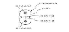
図3に本発明の光ファイバケーブルの第1の実施形態を示す。本形態の光ファイバケーブル21は、断面形状小判形のシース24内に、2本のテンションメンバ23と、テンションメンバ23間の中央に光ファイバ心線22を配置したものである。光ファイバ心線22にはモードフィールド径が8.0〜8.8μmのシングルモードファイバを使用するのが好ましい。また、クラッドに複数の空孔を設けたホーリ光ファイバを使用しても良い。かかる光ファイバは優れた曲げ損失特性を有するので、光ファイバケーブルを大きく曲げても光の損失を低く抑えられる。テンションメンバ23はガラス繊維強化樹脂線状物からなる。テンションメンバ23には熱可塑性樹脂例えば、ポリオレフィン、ポリエステル、ポリアミド等で被覆しても良い。シースには光ファイバ心線を取り出すためのノッチが設けられている。本実施形態の光ファイバケーブルは一般住宅やビルなどの配線に用いられる(ドロップケーブルとも言う)。 FIG. 3 shows a first embodiment of the optical fiber cable of the present invention. The optical fiber cable 21 of this embodiment is configured by arranging two tension members 23 and an optical fiber core wire 22 at the center between the tension members 23 in a sheath 24 having an oval cross-sectional shape. The optical fiber core 22 is preferably a single mode fiber having a mode field diameter of 8.0 to 8.8 μm. In addition, a holey optical fiber having a plurality of holes in the cladding may be used. Since such an optical fiber has excellent bending loss characteristics, even if the optical fiber cable is bent greatly, the optical loss can be kept low. The tension member 23 is made of a glass fiber reinforced resin linear material. The tension member 23 may be covered with a thermoplastic resin such as polyolefin, polyester, polyamide or the like. The sheath is provided with a notch for taking out the optical fiber core wire. The optical fiber cable of the present embodiment is used for wiring in a general house or building (also referred to as a drop cable).
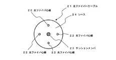
図4に本発明の光ファイバケーブルの第2の実施形態を示す。本実施形態の光ファイバケーブル21は、円形のシース24内に、テンションメンバ23を中心にしてその周囲に光ファイバ心線22を4本を配置したものである。テンションメンバ23はガラス繊維強化樹脂線状物からなる。 FIG. 4 shows a second embodiment of the optical fiber cable of the present invention. The optical fiber cable 21 of the present embodiment is one in which four optical fiber core wires 22 are arranged around a tension member 23 in a circular sheath 24 around the tension member 23. The tension member 23 is made of a glass fiber reinforced resin linear material.
石英系の光ファイバはガラス表面の引張り応力による静疲労によって強度が劣化し破断に至る。そのため光ファイバケーブルは抗張力体、いわゆるテンションメンバを用いてその破断に至るまでの時間すなわち光ファイバ寿命を支配する伸び歪を減少させている。光ファイバ寿命は以下の推定式によって算出される。(出典 満永他:”スクリーニング試験による光ファイバ強度試験法” 電子情報通信学会論文誌、J66−B、No.7)
Tr:光ファイバが破断に至る時間
εr:引張歪み
L:ファイバ全長
F:破断確率
Np:プルーフ試験時の破断確率
εp:プルーフ歪み
tp:プルーフ時間
m:累積破断分布の傾き
n:疲労係数
予め設定した寿命推定年数及び各種パラメータを用い、本式によって許容される引張歪εrが算出される。実用上光ファイバケーブルを使用する上で、この引張歪εrは0.2%以上であることが従来から要求されており、近年では0.3%以上であることが要求されている。Tr: Time until optical fiber breaks εr: Tensile strain L: Full length of fiber F: Probability of rupture Np: Probability of rupture during proof test εp: Proof strain tp: Proof time m: Slope of cumulative rupture distribution n: Fatigue coefficient The allowable tensile strain εr is calculated by this equation using the estimated life span and various parameters. In practical use of an optical fiber cable, the tensile strain εr has been conventionally required to be 0.2% or more, and in recent years, it has been required to be 0.3% or more.
光ファイバケーブルには、敷設や配線などの作業時や敷設後の周囲の環境(例えば、風圧)によりさまざまな張力が加わる。したがって光ファイバケーブルは、敷設や配線などの作業性を低下させず、敷設後の周囲の環境に耐えうるような最低限の許容張力が必要である。この最低限の許容張力は、実用上光ファイバケーブルを使用する上で、2.0kgf以上であることが要求されている。また、好適には、2.6kgf以上であることが好ましい。 Various tensions are applied to the optical fiber cable depending on the surrounding environment (for example, wind pressure) during the work such as laying and wiring or after the laying. Therefore, the optical fiber cable requires a minimum allowable tension that can withstand the surrounding environment after laying without deteriorating workability such as laying and wiring. This minimum allowable tension is required to be 2.0 kgf or more in practical use of the optical fiber cable. Moreover, it is preferable that it is 2.6 kgf or more suitably.
光ファイバケーブルの許容張力はテンションメンバの許容張力に依存し、テンションメンバの許容張力Tは、
T=EAεr
で表される。ここでEは引張弾性率、Aはテンションメンバの断面積、εrは上記した許容される引張歪である。The allowable tension of the optical fiber cable depends on the allowable tension of the tension member, and the allowable tension T of the tension member is
T = EAεr
It is represented by Here, E is the tensile elastic modulus, A is the cross-sectional area of the tension member, and εr is the allowable tensile strain described above.
本発明の光ファイバケーブルのテンションメンバとして使用するガラス繊維強化樹脂線状物は、ガラス繊維とマトリックス樹脂から構成され、ガラス繊維の弾性率と含有率をそれぞれEf、Vf、マトリックス樹脂の弾性率と含有率をそれぞれEm、VmとするとEは、
E=EfVf+EmVm
と表される。また、テンションメンバの直径をdとすると、断面積AはA=π(d/2)2であるから、テンションメンバの許容張力Tは
T=(EfVf+EmVm)π(d/2)2εr
となる。The glass fiber reinforced resin linear material used as the tension member of the optical fiber cable of the present invention is composed of glass fiber and matrix resin, and the elastic modulus and content rate of the glass fiber are Ef, Vf, and the elastic modulus of the matrix resin, respectively. If the contents are Em and Vm, respectively,
E = EfVf + EmVm
It is expressed. If the diameter of the tension member is d, the cross-sectional area A is A = π (d / 2)2 , and therefore the allowable tension T of the tension member is T = (EfVf + EmVm) π (d / 2)2 εr
It becomes.
したがって、本発明の光ファイバケーブルのテンションメンバとして使用するガラス繊維強化線状物は、実際に光ファイバケーブルを使用する上で要求される引張歪εr(%/100)と許容張力T´(kgf)に対して、ガラス繊維の弾性率Ef(GPa)、ガラス繊維の含有率Vf(%/100)、マトリックス樹脂の弾性率Em(GPa)、マトリックス樹脂の含有率Vm(%/100)、ガラス繊維強化樹脂線状物の直径d(mm)として(1GPa=1.02×104kgf/cm2)、
(EfVf+EmVm)d2≧4T´/1.02nπεr
の関係を満たすものである。ここでnは光ファイバケーブルに使用されているテンションメンバの本数である(例えば、ドロップケーブルではn=2)。(EfVf+EmVm)d2は引張歪が0.3、許容張力2.0kgfの場合、8.3/n以上であることが好ましい。引張歪が0.3、許容張力2.6kgfの場合、10.8/n以上であることが好ましい。引張歪が0.2、許容張力2.0kgfの場合、12.5/n以上であることが好ましい。引張歪が0.2、許容張力2.6の場合、16.3/n以上であることが好ましい。なお、テンションメンバの直径dは使用する光ファイバケーブル内に納めることが出来る径を上限とする。住宅やビルの配線用の光ファイバケーブルに使用するものとして、dは0.6mm以下であることが好ましい。Therefore, the glass fiber reinforced linear material used as the tension member of the optical fiber cable according to the present invention has a tensile strain εr (% / 100) and an allowable tension T ′ (kgf) that are actually required when using the optical fiber cable. ) Glass fiber elastic modulus Ef (GPa), glass fiber content Vf (% / 100), matrix resin elastic modulus Em (GPa), matrix resin content Vm (% / 100), glass As the diameter d (mm) of the fiber reinforced resin linear material (1 GPa = 1.02 × 10⁴ kgf / cm2 ),
(EfVf + EmVm) d2 ≧ 4T ′ / 1.02nπεr
It satisfies the relationship. Here, n is the number of tension members used in the optical fiber cable (for example, n = 2 for a drop cable). (EfVf + EmVm)d 2 tensile strain is 0.3, if the allowable tension 2.0 kgf, is preferably 8.3 / n or more. When the tensile strain is 0.3 and the allowable tension is 2.6 kgf, it is preferably 10.8 / n or more. When the tensile strain is 0.2 and the allowable tension is 2.0 kgf, it is preferably 12.5 / n or more. When the tensile strain is 0.2 and the allowable tension is 2.6, it is preferably 16.3 / n or more. The upper limit of the diameter d of the tension member is the diameter that can be accommodated in the optical fiber cable to be used. For use in an optical fiber cable for wiring in a house or building, d is preferably 0.6 mm or less.
本発明の光ファイバケーブルのテンションメンバに用いるガラス繊維強化樹脂線状物は、ガラス繊維の破断伸びが5%以上であり、且つマトリックス樹脂の破断伸びが5%以上であり、ガラス繊維の弾性率Efとマトリックス樹脂の弾性率Emの比が22以上である条件を満たすガラス繊維とマトリックス樹脂により形成されている。ガラス繊維は破断率5%以上であり、大きい弾性率を有するので、優れた柔軟性を有する。そしてEf/Emの比が22以上を満たす弾性率のマトリックス樹脂によって前記のガラス繊維を固着するので、前記のガラス繊維の柔軟性を失うことなくガラス繊維強化樹脂線状物が形成でき、優れた柔軟性を有するテンションメンバとして使用可能となる。 The glass fiber reinforced resin linear material used for the tension member of the optical fiber cable of the present invention has a glass fiber breaking elongation of 5% or more and a matrix resin breaking elongation of 5% or more. The glass fiber and the matrix resin satisfy the condition that the ratio of the elastic modulus Em of Ef to the matrix resin is 22 or more. The glass fiber has a breakage rate of 5% or more and a large elastic modulus, and thus has excellent flexibility. And since the glass fiber is fixed by a matrix resin having an elastic modulus satisfying an Ef / Em ratio of 22 or more, a glass fiber reinforced resin linear product can be formed without losing the flexibility of the glass fiber. It can be used as a flexible tension member.
本発明の光ファイバケーブルのテンションメンバに用いるガラス繊維強化樹脂線状物は、ガラス繊維の破断伸びとマトリックス樹脂の破断伸びの比(マトリックス樹脂の破断伸び/ガラス繊維の破断のび)が0.93〜1.27の範囲内であることが好ましい。この範囲内であることにより、ガラス繊維の破断のびとマトリックス樹脂の破断伸びとの大きさの差が小さいので、かかる差に起因する曲げ特性の低下を抑制でき、優れた柔軟性を有するガラス繊維強化樹脂線状物が形成できる。 The glass fiber reinforced resin linear material used for the tension member of the optical fiber cable of the present invention has a ratio of the glass fiber breaking elongation to the matrix resin breaking elongation (matrix resin breaking elongation / glass fiber breaking elongation) of 0.93. It is preferable to be within the range of ˜1.27. By being within this range, since the difference in size between the breakage of the glass fiber and the elongation at break of the matrix resin is small, it is possible to suppress a decrease in bending characteristics due to such a difference, and the glass fiber has excellent flexibility. A reinforced resin linear object can be formed.
ガラス繊維強化樹脂線状物を構成するガラス繊維の含有率Vfとマトリックス樹脂の含有率Vmとの関係において(Vf+Vm=1)、ガラス繊維の含有率Vfは0.6以上0.88以下であることが好ましい。0.6未満であるとガラス繊維の含有率が小さすぎるため、必要とされる強度を得ることが難しいからである。また0.88より大きいとマトリックス樹脂の含有率が小さすぎるため、マトリックス樹脂によってガラス繊維を固着化するのが困難になるからである。好適には、0.65以上0.80以下であると良い。 In the relationship between the glass fiber content Vf constituting the glass fiber reinforced resin linear material and the matrix resin content Vm (Vf + Vm = 1), the glass fiber content Vf is 0.6 or more and 0.88 or less. It is preferable. This is because if it is less than 0.6, the glass fiber content is too small and it is difficult to obtain the required strength. On the other hand, if the ratio is larger than 0.88, the content of the matrix resin is too small, so that it is difficult to fix the glass fiber with the matrix resin. Preferably, it is 0.65 or more and 0.80 or less.
次に本発明の光ファイバケーブルのテンションメンバとして用いるガラス繊維強化樹脂線状物の実施形態について説明する。 Next, an embodiment of a glass fiber reinforced resin linear material used as a tension member of the optical fiber cable of the present invention will be described.
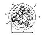
図1に示すように、本発明のガラス繊維強化樹脂線状物1は、ガラス繊維2と、マトリックス樹脂4とを含む。30〜100本のガラス繊維2のモノフィラメントがヤーン3を形成してもよく、30〜80本のガラス繊維2のモノフィラメントがヤーン3を形成することが好ましい。ヤーン3の横断面は、実質的に円形であることが好ましい。ヤーン3とヤーン3とは互いに接触していてもよいし、接触していなくてもよい。ガラス繊維強化樹脂線状物1は、4〜15本のヤーンを含むことが好ましく、5〜12本のヤーンを含むことが更に好ましい。ガラス繊維強化樹脂線状物1の直径は、0.6mm以下であることが好ましく、0.55mm以下であることが更に好ましい。本発明では、このように細いガラス繊維強化樹脂線状物であっても十分な引張り強度を保持することができる。また、ガラス繊維強化樹脂線状物1の直径は、0.1mm以上であることが好ましく、0.2mm以上であることが更に好ましい。 As shown in FIG. 1, the glass fiber reinforced resin linear product 1 of the present invention includes
マトリックス樹脂4の外周は、熱可塑性樹脂6で被覆されている場合がある。熱可塑性樹脂としては、例えば、ポリオレフィン、ポリエステル、ポリアミド等が用いられ、ポリエチレンのようなポリオレフィンが好ましい。なお、熱可塑性樹脂6は必須の構成ではない。 The outer periphery of the
本発明では、ガラス繊維の破断伸びが5.0%以上である。これにより、ガラス繊維樹脂線状物は、高い柔軟性を有し、最小曲げ直径を減少させることができる。ガラス繊維の破断伸びは、JIS R 3420に規定する「ガラス繊維一般試験方法(4)引張り強さ」に従って測定する。文献によっては、破断伸びを最大伸び率ということもある。 In the present invention, the breaking elongation of the glass fiber is 5.0% or more. Thereby, a glass fiber resin linear thing has high softness | flexibility, and can reduce a minimum bending diameter. The breaking elongation of the glass fiber is measured according to “Glass Fiber General Test Method (4) Tensile Strength” defined in JIS R 3420. Depending on the literature, the elongation at break may be referred to as the maximum elongation.
ガラス繊維の弾性率が70GPa以上であることが好ましく、80GPa以上であることが更に好ましい。ガラス繊維樹脂線状物に高い柔軟性を付与し、最小曲げ直径を減少させるためである。 The elastic modulus of the glass fiber is preferably 70 GPa or more, and more preferably 80 GPa or more. This is to impart high flexibility to the glass fiber resin wire and reduce the minimum bending diameter.
上記のような物性を示すガラス繊維としては、例えば、55〜79.9重量%のSiO2、12.6〜32重量%のAl2O3、4〜20重量%のMgOを含むガラス組成物が挙げられる。このガラス組成物は、また、1重量%未満のZrO2を含んでいてもよい。例えば、米国特許第3,402,055に記載されているガラス繊維を用いることができる。ガラス繊維としては、日東紡績(株)から販売されている高強度ガラス繊維(商品名「Tガラス」)が、好適に使用できる。As the glass fiber showing the above physical properties, for example, from 55 to 79.9 wt% ofSiO 2, 12.6-32
ガラス繊維の表面がエポキシシラン処理されていることが好ましい。ガラス繊維とマトリックス樹脂との界面における濡れ性が向上するからである。 It is preferable that the surface of the glass fiber is treated with epoxy silane. This is because the wettability at the interface between the glass fiber and the matrix resin is improved.
本発明のガラス繊維強化樹脂線状物に含まれるマトリックス樹脂は、25℃にて粘度が15000mPa・s以下の液状エポキシ樹脂を、熱カチオン重合触媒又は酸無水物により硬化させたものである。このマトリックス樹脂は、ガラス繊維で強化されていない場合であっても、その破断伸び及び弾性率が向上する。また、液状エポキシ樹脂は、25℃にて粘度が15000mPa・s以下なので、未硬化の樹脂組成物の段階にて、ガラス繊維との濡れ性が良く、硬化後にガラス繊維と良好な接着性を有する。 The matrix resin contained in the glass fiber reinforced resin linear material of the present invention is obtained by curing a liquid epoxy resin having a viscosity of 15000 mPa · s or less at 25 ° C. with a thermal cationic polymerization catalyst or an acid anhydride. Even when this matrix resin is not reinforced with glass fibers, its elongation at break and elastic modulus are improved. Further, since the liquid epoxy resin has a viscosity of 15000 mPa · s or less at 25 ° C., it has good wettability with the glass fiber at the stage of the uncured resin composition, and has good adhesion with the glass fiber after curing. .
また、マトリックス樹脂の破断伸びλが5.0%以上であり、且つマトリックス樹脂の弾性率が2GPa以上であることが好ましい。この条件を満たした場合には、ガラス繊維強化樹脂線状物が破断しない限界の曲げの直径Dとガラス繊維樹脂線状物の直径dの比であるD/dが安定的に20以下になるからである。一方、D/dが10以上であることが好ましく、12以上であることが更に好ましい。なお、マトリックス樹脂の物性については、ガラス繊維が含まれていない状態で、樹脂組成物を硬化させて、マトリックス樹脂を形成し、その破断伸び及び弾性率を測定する。 Further, it is preferable that the breaking elongation λ of the matrix resin is 5.0% or more and the elastic modulus of the matrix resin is 2 GPa or more. When this condition is satisfied, the ratio D / d, which is the ratio of the bending diameter D at which the glass fiber reinforced resin linear material does not break and the diameter d of the glass fiber resin linear material, is stably 20 or less. Because. On the other hand, D / d is preferably 10 or more, and more preferably 12 or more. As for the physical properties of the matrix resin, the resin composition is cured in a state in which no glass fiber is contained to form a matrix resin, and its elongation at break and elastic modulus are measured.
液状エポキシ樹脂は1種を用いてもよいし、2種以上の混合物を用いてもよい。2種以上の混合物の場合には、少なくとも一つの液状エポキシ樹脂の粘度が、25℃にて15000mPa・s以下であればよく、2種以上の混合物の全体として、25℃にて15000mPa・s以下であることが好ましい。 One type of liquid epoxy resin may be used, or a mixture of two or more types may be used. In the case of a mixture of two or more, the viscosity of at least one liquid epoxy resin may be 15000 mPa · s or less at 25 ° C., and the whole of the two or more mixtures is 15000 mPa · s or less at 25 ° C. It is preferable that
もっとも、未硬化の樹脂組成物には、液状エポキシ樹脂の他に、硬化剤(熱カチオン重合触媒又は酸無水物)及び所望により他の成分が含まれている。そして、未硬化の樹脂組成物の粘度は、25℃にて10000Pa・s以下であることが好ましい。未硬化の樹脂組成物の粘度が低い方が、未硬化の樹脂組成物がガラス繊維の間に浸入し易くなるからである。 However, the uncured resin composition contains a curing agent (thermal cationic polymerization catalyst or acid anhydride) and other components as desired in addition to the liquid epoxy resin. The viscosity of the uncured resin composition is preferably 10,000 Pa · s or less at 25 ° C. This is because the lower the viscosity of the uncured resin composition, the easier the uncured resin composition enters between the glass fibers.
本明細書では、「未硬化の樹脂組成物」とは、熱による硬化をする前の樹脂組成物をいい、典型的には、80〜200℃の雰囲気温度にて硬化をする前の樹脂組成物をいう。「未硬化の樹脂組成物」であっても、室温にて、わずかに硬化が進行している場合がある。
(1)液状エポキシ樹脂
液状エポキシ樹脂は、エポキシシクロヘキサン環又は2,3−エポキシプロピロキシ基(2,3-epoxypropyloxy)を含むことが好ましい。熱カチオン重合触媒を用いる場合には、エポキシシクロヘキサン環を含む液状エポキシ樹脂が特に好ましい。液状エポキシ樹脂が低粘度であるのにもかかわらず、カチオン重合性が高く、硬化後物性が優れているからである。なお、2,3−エポキシプロピロキシ基を含むということは、グリシジルエーテル型エポキシ樹脂ということである。In this specification, the “uncured resin composition” refers to a resin composition before being cured by heat, and typically, the resin composition before being cured at an ambient temperature of 80 to 200 ° C. Say things. Even an “uncured resin composition” may be slightly cured at room temperature.
(1) Liquid epoxy resin The liquid epoxy resin preferably contains an epoxycyclohexane ring or a 2,3-epoxypropyloxy group (2,3-epoxypropyloxy). When using a thermal cationic polymerization catalyst, a liquid epoxy resin containing an epoxycyclohexane ring is particularly preferred. This is because, despite the low viscosity of the liquid epoxy resin, the cationic polymerizability is high and the physical properties after curing are excellent. In addition, including a 2,3-epoxypropyloxy group means a glycidyl ether type epoxy resin.
エポキシシクロヘキサン環を含む液状エポキシ樹脂としては、例えば、3,4−エポキシシクロヘキサン酸3,4−エポキシシクロヘキシルメチル(1)(ダイセル化学、セロキサイド2021P、25℃での粘度:350mPa・s)、1−(1,2−エポキシ−2−プロパニル)−3−メチル−3,4−エポキシシクロヘキサン(2)(ダイセル化学、セロキサイド3000、25℃での粘度が3500mPa・s以下)、3,4−エポキシシクロヘキサン酸エステル(3)、(ダイセル化学、セロキサイド2081、25℃での粘度:350mPa・s)が挙げられる。これらの化学式を下記に示す。
2,3−エポキシプロピロキシ基を含む液状エポキシ樹脂としては、ビスフェノールFジグリシジルエーテル、ビス(4−(2,3−エポキシプロピロキシ)フェニル)メタン(4)(旭電化工業、EP−4901、粘度:3500mPa・s)、水素添加ビスフェノールAジグリシジルエーテル、2,2−ビス(4−(2,3−エポキシプロピロキシ)シクロヘキシル)プロパン(5)(大日本インキ化学工業、エピクロン830)、水素添加ビスフェノールFジグリシジルエーテル、ビス(4−(2,3−エポキシプロピロキシ)シクロヘキシル)メタン(6)(旭電化工業、EP−4080E、粘度:2000mPa・s;ジャパンエポキシレジン、YX8000、粘度:1800mPa・s)が挙げられる。
反応性希釈剤としては、1,4−ビス(2,3−エポキシプロピロキシメチル)シクロヘキサン(8)(旭電化工業、EP−4085、粘度:45mPa・s)、ジシクロペンタジエンジメタノールのジグリシジルエーテル(9)(旭電化工業、EP−4088、粘度:335mPa・s)、パラ-t-ブチルフェニル=グリシジル=エーテル(10)(ナガセケムテックス、デナコールEX146、粘度:20mPa・s)、イソプロピルフェニル=グリシジル=エーテル(11)(大日本インキ化学工業、エピクロン520、粘度:15mPa・s)が挙げられる。
次に、硬化剤が酸無水物である場合に主に用いられる液状エポキシ樹脂について述べる。 Next, the liquid epoxy resin mainly used when the curing agent is an acid anhydride will be described.
液状エポキシ樹脂としては、ジアルキルシクロヘキセン誘導体のジグリシジルエステル(14)(ジャパンエポキシレジン、エピコート871、粘度:650mPa・s)を用いることができる。
熱カチオン重合触媒としては、加熱により活性化されエポキシ基の開環を誘発する触媒が用いられ、第四級アンモニウム塩、ホスホニウム塩およびスルホニウム塩等の各種オニウム塩、並びに、有機金属錯体類などが例示される。As the liquid epoxy resin, diglycidyl ester (14) of a dialkylcyclohexene derivative (Japan Epoxy Resin, Epicoat 871, viscosity: 650 mPa · s) can be used.
スルホニウム塩としては、例えば、式(22)及び(23)で示されるヘテロ環誘導体が挙げられる(旭電化工業、アデカオプトンCP−66およびアデカオプトンCP−77)。
また、カチオン重合開始剤の配合割合は、未硬化の樹脂組成物100重量部に対し、0.1〜5重両部の範囲とするのが好ましく、更に好ましくは0.3〜3重両部である。
(3)酸無水物
酸無水物は、水素添加されていてもよい無水フタル酸骨格を有することが好ましい。酸無水物としては、例えば、無水メチルテトラヒドロフタル酸(Me−THPA)(Quinhard200(日本ゼオン)、HN−2200(日立化成工業)、リカシッドMT−500(新日本理化))、無水メチルヘキサヒドロフタル酸(Me−HHPA)(Quinhard500(日本ゼオン)、HN−5500(日立化成工業)、リカシッドMH−700(新日本理化)),無水メチルナジック酸(25)(MHAC−P(日立化成工業))、無水メチルナジック酸の水素添加物(26)(HNA(新日本理化)),アルキル変性酸無水物(27)(エピキュアYH−306、エピキュアYH−307(ジャパンエポキシレジン))などが挙げられる。
(3)平均分子量900以上のビスフェノールA型エポキシ樹脂
本発明では、マトリックス樹脂は、前記液状エポキシ樹脂を平均分子量900以上のビスフェノールA型エポキシ樹脂と共に硬化させたものであることが好ましい。平均分子量900以上のビスフェノールA型エポキシ樹脂は、一般的には、25℃にて固体である。Further, the blending ratio of the cationic polymerization initiator is preferably in the range of 0.1-5 double parts, more preferably 0.3-3 double parts, with respect to 100 parts by weight of the uncured resin composition. It is.
(3) Acid anhydride The acid anhydride preferably has a phthalic anhydride skeleton which may be hydrogenated. Examples of the acid anhydride include methyltetrahydrophthalic anhydride (Me-THPA) (Quinhard 200 (Nippon Zeon), HN-2200 (Hitachi Chemical Co., Ltd.), Ricacid MT-500 (New Nippon Rika)), methyl hexahydrophthalic anhydride Acid (Me-HHPA) (Quinhard 500 (Nippon Zeon), HN-5500 (Hitachi Chemical Co., Ltd.), Ricacid MH-700 (Shin Nippon Rika)), Methyl nadic anhydride (25) (MHAC-P (Hitachi Chemical Industry)) , Hydrogenated methyl nadic acid (26) (HNA (New Nippon Rika)), alkyl-modified acid anhydride (27) (Epicure YH-306, Epicure YH-307 (Japan Epoxy Resin)) and the like.
(3) Bisphenol A-type epoxy resin having an average molecular weight of 900 or more In the present invention, the matrix resin is preferably obtained by curing the liquid epoxy resin together with a bisphenol A-type epoxy resin having an average molecular weight of 900 or more. A bisphenol A type epoxy resin having an average molecular weight of 900 or more is generally solid at 25 ° C.
ビスフェノールA型エポキシ樹脂(28)の一般式は、下記の通りである。
例えば、ジャパンエポキシレジンのエピコート1001(平均分子量:900)、エピコート1002(平均分子量:1200)、エピコート1003(平均分子量:1300)、エピコート1055(平均分子量:1600)を用いることができる。未硬化の樹脂組成物の粘度上昇が比較的低く抑えられ、硬化後に充分な靭性を付与しやすいという観点からエピコート1002が望ましい。The general formula of the bisphenol A type epoxy resin (28) is as follows.
For example, Epicoat 1001 (average molecular weight: 900), Epicoat 1002 (average molecular weight: 1200), Epicoat 1003 (average molecular weight: 1300), and Epicoat 1055 (average molecular weight: 1600) of Japan Epoxy Resin can be used. Epicoat 1002 is desirable from the standpoint that the increase in viscosity of the uncured resin composition is suppressed to a relatively low level, and sufficient toughness is easily imparted after curing.
なお、本発明では、平均分子量900以上のビスフェノールA型エポキシ樹脂(28)の代わりに、繰り返し単位がビスフェノールAの水素添加物であるエポキシ樹脂を用いてもよい。
(4)可撓性付与剤
可撓性付与剤としては、例えば、カルボン酸末端脂肪族ポリエステルのエポキシ樹脂アダクト物(29)、例えば、SD551(チバ・スペシャルティ・ケミカルズ)を用いることができる。
(4) Flexibility imparting agent As the flexibility imparting agent, for example, a carboxylic acid-terminated aliphatic polyester epoxy resin adduct (29), for example, SD551 (Ciba Specialty Chemicals) can be used.
また、SD665(チバ・スペシャルティ・ケミカルズ)を用いることができる。これは、SD551(チバ・スペシャルティ・ケミカルズ)の末端のエポキシ部分が、下記式(30)に置換されている。
更に、カルボン酸末端アクリロニトリル-ブタジエン共重合体(33)(CTBN)、例えばHYCAR CTBN1300×13、HYCAR CTBN1300×8、HYCAR CTBN1300×9など(宇部興産)、又は、それらのエポキシ樹脂アダクト物(34)を用いることができる。
平均分子量900以上のビスフェノールA型エポキシ樹脂及び可撓性付与剤の配合量の合計は、液状エポキシ樹脂と、平均分子量900以上のビスフェノールA型エポキシ樹脂と、可撓性付与剤との配合量との合計の5〜50重量%であることが好ましく、10〜30重量%であることが更に好ましい。なお、マトリックス樹脂には、平均分子量900以上のビスフェノールA型エポキシ樹脂、可撓性付与剤の双方が含まれていても良いし、何れかが含まれていてもよいし、双方が含まれていなくてもよい。
(5)硬化促進剤
硬化剤として酸無水物を用いた場合には、硬化促進剤を用いることが好ましい。硬化促進剤としては、イミダゾール誘導体を用いることができる。例えば、1−メチルイミダゾール、2−メチルイミダゾール、2−ウンデシルイミダゾール、2−ヘプタデシルイミダゾール等のアルキルイミダゾール;1,2−ジメチルイミダゾール、2−エチル−4−メチルイミダゾール等のジアルキルイミダゾール;2−フェニルイミダゾール等のアリールイミダゾール;2−フェニル−4−メチルイミダゾール、1−ベンジル−2−メチルイミダゾール、1−シアノエチル−2−メチルイミダゾール、1−シアノエチル−2−エチル−4−メチルイミダゾール、1−シアノエチル−2−ウンデシルイミダゾール、1−シアノエチル−2−フェニルイミダゾール、1−シアノエチル−2−エチル−4−メチルイミダゾリウムトリメリテイト、1−シアノエチル−2−ウンデシルイミダゾリウムトリメリテイト、1−シアノエチル−2−フェニルイミダゾリウムトリメリテイト、2,4−ジアミノ−6−(2’−メチルイミダゾリル−(1’))−エチル−s−トリアジン、2,4−ジアミノ−6−(2’−ウンデシルイミダゾリル)−エチル−s−トリアジン、2,4−ジアミノ−6−(2’−エチル−4−メチルイミダゾリル−(1’))−エチル−s−トリアジン、2,4−ジアミノ−6−(2’−メチルイミダゾリル−(1’))−エチル−s−トリアジン イソシアヌル酸付加物、2−フェニルイミダゾール イソシアヌル酸付加物、2−メチルイミダゾール イソシアヌル酸付加物、2−フェニル−4,5−ジヒドロキシメチルイミダゾール、2−フェニル−4−メチル−5−ヒドロキシメチルイミダゾール、1−シアノエチル−2−フェニル−4,5−ジ(2−シアノエトキシ)メチルイミダゾール等を用いることができる。The total blending amount of the bisphenol A type epoxy resin having an average molecular weight of 900 or more and the flexibility imparting agent is the blending amount of the liquid epoxy resin, the bisphenol A type epoxy resin having an average molecular weight of 900 or more, and the flexibility imparting agent. It is preferable that it is 5 to 50 weight% of the sum total of, and it is still more preferable that it is 10 to 30 weight%. The matrix resin may contain both a bisphenol A type epoxy resin having an average molecular weight of 900 or more and a flexibility-imparting agent, or may contain either or both. It does not have to be.
(5) Curing accelerator When an acid anhydride is used as the curing agent, it is preferable to use a curing accelerator. As the curing accelerator, an imidazole derivative can be used. For example, alkyl imidazoles such as 1-methylimidazole, 2-methylimidazole, 2-undecylimidazole and 2-heptadecylimidazole; dialkylimidazoles such as 1,2-dimethylimidazole and 2-ethyl-4-methylimidazole; Aryl imidazoles such as phenyl imidazole; 2-phenyl-4-methylimidazole, 1-benzyl-2-methylimidazole, 1-cyanoethyl-2-methylimidazole, 1-cyanoethyl-2-ethyl-4-methylimidazole, 1-cyanoethyl 2-undecylimidazole, 1-cyanoethyl-2-phenylimidazole, 1-cyanoethyl-2-ethyl-4-methylimidazolium trimellitate, 1-cyanoethyl-2-undecylimidazolium trimellitate 1-cyanoethyl-2-phenylimidazolium trimellitate, 2,4-diamino-6- (2′-methylimidazolyl- (1 ′))-ethyl-s-triazine, 2,4-diamino-6 (2′-undecylimidazolyl) -ethyl-s-triazine, 2,4-diamino-6- (2′-ethyl-4-methylimidazolyl- (1 ′))-ethyl-s-triazine, 2,4- Diamino-6- (2′-methylimidazolyl- (1 ′))-ethyl-s-triazine isocyanuric acid adduct, 2-phenylimidazole isocyanuric acid adduct, 2-methylimidazole isocyanuric acid adduct, 2-phenyl-4 , 5-dihydroxymethylimidazole, 2-phenyl-4-methyl-5-hydroxymethylimidazole, 1-cyanoethyl-2-phenyl- , 5-di (2-cyano-ethoxy) can be used methylimidazole.
また、1,8-ジアザ-ビシクロ(5,4,0)ウンデセン7(DBU)及びその塩類も用いることができる。例えば1,8-ジアザ-ビシクロ(5,4,0)ウンデセン7、(例えば、FCキュアα−1、四国化成工業)、DBU・2エチルヘキサン酸塩(例えば、FCキュアα−2、四国化成工業)、DBU・オクチル酸塩(例えば、U−CAT SA102、サン・アプロ)、DBU・フタル酸塩(例えば、U−CAT SA810、サン・アプロ)、DBUのテトラフェニルボレート(例えば、U−CAT 5002、サン・アプロ)等が用いられる。 In addition, 1,8-diaza-bicyclo (5,4,0) undecene 7 (DBU) and its salts can also be used. For example, 1,8-diaza-bicyclo (5,4,0) undecene 7, (for example, FC Cure α-1, Shikoku Kasei Kogyo), DBU · 2 ethylhexanoate (for example, FC Cure α-2, Shikoku Chemicals) Industrial), DBU octylate (eg U-CAT SA102, Sun Apro), DBU phthalate (eg U-CAT SA810, Sun Apro), DBU tetraphenylborate (eg U-CAT) 5002, Sun Apro).
また、ホスフィン、ホスホニウム塩も用いることができる。ホスフィンには、モノホスフィンとジホスフィンが含まれる。モノホスフィンとしては、例えば、トリフェニルホスフィン、トリトリルホスフィン、トリス(メトキシフェニル)ホスフィン、トリス(パラクロロフェニル)ホスフィン等のトリアリールホスフィン;ジシクロヘキシルフェニルホスフィン等のジシクロアルキルアリールホスフィン;ジフェニルシクロヘキシルホスフィン等のジアリールジシクロアルキルホスフィンが用いられる。ジホスフィンとしては、例えば、ビス(ジフェニルホスフィノ)メタン、1,2−ビス(ジフェニルホスフィノ)エタン、1,3−ビス(ジフェニルホスフィノ)プロパン、1,4−ビス(ジフェニルホスフィノ)ブタン、1,5−ビス(ジフェニルホスフィノ)ペンタン等のα,ω−ビスジアリールアルカンが好ましく用いられる。ホスホニウム塩としては、テトラ−n−ブチルホスホニウムブロマイド等のテトラアルキルホスホニウムハロゲン化物;テトラフェニルホスホニウムブロマイド等のテトラアリールホスホニウムハロゲン化物、アルキルトリアリールホスホニウムハロゲン化物;テトラフェニルホスホニウムテトラフェニルボレート等のテトラアリールホスホニウムテトラアリールボレートが挙げられる。 Further, phosphine and phosphonium salts can also be used. Phosphine includes monophosphine and diphosphine. Examples of the monophosphine include triarylphosphine such as triphenylphosphine, tolylphosphine, tris (methoxyphenyl) phosphine, and tris (parachlorophenyl) phosphine; dicycloalkylarylphosphine such as dicyclohexylphenylphosphine; and diphenylcyclohexylphosphine. Diaryldicycloalkylphosphine is used. Examples of the diphosphine include bis (diphenylphosphino) methane, 1,2-bis (diphenylphosphino) ethane, 1,3-bis (diphenylphosphino) propane, 1,4-bis (diphenylphosphino) butane, Α, ω-bisdiarylalkanes such as 1,5-bis (diphenylphosphino) pentane are preferably used. Examples of phosphonium salts include tetraalkylphosphonium halides such as tetra-n-butylphosphonium bromide; tetraarylphosphonium halides such as tetraphenylphosphonium bromide, alkyltriarylphosphonium halides; tetraarylphosphonium such as tetraphenylphosphonium tetraphenylborate Tetraaryl borates are mentioned.
3級アミン類も用いることができる。例えば、1,3,5−トリスジメチルアミノメチルフェノール(例えば、アデカハードナーEHC−30、旭電化工業)を用いることができる。3級アミンの三塩化ホウ素錯体(DY9577、チバ・スペシャルティ・ケミカルズ)を用いることもできる。 Tertiary amines can also be used. For example, 1,3,5-trisdimethylaminomethylphenol (for example, Adeka Hardener EHC-30, Asahi Denka Kogyo) can be used. A tertiary amine boron trichloride complex (DY9577, Ciba Specialty Chemicals) can also be used.
これらの硬化促進剤はそれ自体液状かあるいはエポキシ樹脂に可溶の固体であり、未硬化の樹脂組成物に溶解させて使用する。硬化促進剤の添加量は、エポキシ樹脂100重量部に対して0.8〜20重量部添加するのが好ましく、更には1〜8重量部添加するのが好ましい。 These curing accelerators are themselves liquid or solid soluble in an epoxy resin, and are used after being dissolved in an uncured resin composition. The addition amount of the curing accelerator is preferably 0.8 to 20 parts by weight, more preferably 1 to 8 parts by weight, based on 100 parts by weight of the epoxy resin.
また、一液型酸無水物硬化系エポキシ樹脂組成物のシェルフライフを延長する目的で通常使用されているマイクロカプセル型潜在性硬化促進剤、例えばノバキュアHX−3088,HX−3741,HX−3921(旭化成工業)も、速硬化性を有しつつポットライフを延長させることを目的として使用することができる。直径5μm程度の微粒子状であるこれらの促進剤は、細い隙間には浸透することができないため、先述の樹脂溶解型促進剤と併用することにより、マイクロカプセル型促進剤の粒子径以下の隙間に浸透した樹脂組成物も効率よく硬化させることができる。 Further, a microcapsule type latent curing accelerator usually used for the purpose of extending the shelf life of the one-component acid anhydride-curing epoxy resin composition, such as NovaCure HX-3088, HX-3741, HX-3922 ( Asahi Kasei Kogyo) can also be used for the purpose of extending the pot life while having fast curability. Since these accelerators in the form of fine particles having a diameter of about 5 μm cannot penetrate into narrow gaps, they can be used together with the above-mentioned resin-dissolving accelerators to form gaps smaller than the particle size of the microcapsule accelerators. The penetrated resin composition can also be cured efficiently.
また、未硬化の樹脂組成物は、微量の消泡剤を含有することが好ましい。消泡剤としては、シリコーンを用いることができる。 Moreover, it is preferable that an uncured resin composition contains a trace amount antifoamer. Silicone can be used as the antifoaming agent.
光ファイバケーブルのテンションメンバとして用いるガラス繊維強化樹脂線状物の製造方法は、破断のびが5%以上のガラス繊維と、マトリックス樹脂とを含むガラス繊維強化樹脂線状物の製造方法であって、25℃にて粘度が15000mPa・s以下の液状エポキシ樹脂を、熱カチオン重合触媒又は酸無水物により硬化させる工程を含むことを特徴とする。 A method for producing a glass fiber reinforced resin linear material used as a tension member of an optical fiber cable is a method for producing a glass fiber reinforced resin linear material containing a glass fiber having a fracture elongation of 5% or more and a matrix resin, It includes a step of curing a liquid epoxy resin having a viscosity of 15000 mPa · s or less at 25 ° C. with a thermal cationic polymerization catalyst or an acid anhydride.
この液状エポキシ樹脂と、熱カチオン重合触媒又は酸無水物とを少なくとも含む未硬化の樹脂組成物を80〜200℃の雰囲気温度にて10分以内で硬化させることが好ましく、90〜180℃の雰囲気温度にて5分以内で硬化させることが更に好ましく、90℃〜160℃の雰囲気温度にて3分以内で硬化させることが更になお好ましい。硬化時間が短い方が、ガラス繊維を引張る速度を早くすることができるので、硬化用金型の長さを短くすることができ、また、製造時間を短縮することができるからである。 It is preferable to cure the uncured resin composition containing at least the liquid epoxy resin and the thermal cation polymerization catalyst or acid anhydride at an atmospheric temperature of 80 to 200 ° C. within 10 minutes, and an atmosphere of 90 to 180 ° C. It is more preferable to cure within 5 minutes at a temperature, and still more preferable to cure within 3 minutes at an atmospheric temperature of 90 ° C to 160 ° C. This is because the shorter the curing time, the faster the glass fiber can be pulled, so that the length of the curing mold can be shortened and the production time can be shortened.
未硬化の樹脂組成物の粘度が、25℃にて10000mPa・s以下であることが好ましく、25℃にて9000mPa・s以下であることが更に好ましい。未硬化の樹脂組成物がガラス繊維の間に入り込み易くなり、濡れ性が向上するからである。 The viscosity of the uncured resin composition is preferably 10,000 mPa · s or less at 25 ° C., more preferably 9000 mPa · s or less at 25 ° C. This is because the uncured resin composition easily enters between the glass fibers and improves the wettability.
以下、本発明について、好適な実施例により詳細に説明するが、本発明の範固は、以下の実施例に限定されるものでない。
実施例1〜3
日東紡績(株)から販売されている高強度ガラス繊維(商品名「Tガラス」、破断伸びが5.5%,弾性率が84.3GPa)を用いた。Tガラスは、65重量%のSiO2、23重量%のAl2O3、11重量%のMgO、1重量%未満のZrO2を含む。この高強度ガラス繊維の詳細な仕様を表1に示す。
Examples 1-3
High-strength glass fiber (trade name “T glass”, elongation at break of 5.5%, elastic modulus of 84.3 GPa) sold by Nitto Boseki Co., Ltd. was used. T glass containingSiO 2 of 65 wt%, 23 wt% ofAl 2O 3, 11 wt% of MgO, ZrO2 less than 1 wt%. Detailed specifications of the high-strength glass fiber are shown in Table 1.
まず、成分(1)、(2)、(3)及び(6)を表2に記載の配合比で混合し、ケトルにて100℃、減圧下で1時間攪拌し、均一に溶解させた。その後、成分(4)を表2に記載の量仕込んで減圧攪拌し、均一に溶解させた。そして、室温まで冷却し、所定量の成分(5)を仕込み、30分減圧攪拌した。110メッシュでろ過し、遮光容器に排出し、未硬化の樹脂組成物を得た。 First, components (1), (2), (3), and (6) were mixed at a blending ratio shown in Table 2, and stirred in a kettle at 100 ° C. under reduced pressure for 1 hour to be uniformly dissolved. Thereafter, the amount of component (4) shown in Table 2 was charged and stirred under reduced pressure to dissolve uniformly. And it cooled to room temperature, the predetermined amount of component (5) was prepared, and it stirred under reduced pressure for 30 minutes. It filtered with 110 mesh, discharged | emitted in the light shielding container, and obtained the uncured resin composition.
この未硬化の樹脂組成物を予め30度に温度制御された含浸槽に充填し、30℃に維持した。このとき、含浸槽内の樹脂の粘度は実施例1、2及び3で、それぞれ、3000mPa・s、5000mPa・s、及び6000mPa・sであった。 The uncured resin composition was filled in an impregnation tank whose temperature was controlled at 30 degrees in advance and maintained at 30 ° C. At this time, the viscosity of the resin in the impregnation tank was 3000 mPa · s, 5000 mPa · s, and 6000 mPa · s in Examples 1, 2, and 3, respectively.
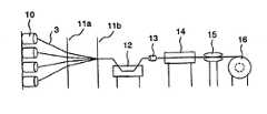
図2で、複数のクリール10からヤーンを引出した。ヤーンをガイド11a及びガイド11bを通して収束させ、次いで、含浸槽12に浸漬して未硬化の樹脂組成物を含浸させた。次に、絞りノズル13により、線状物を所定形状に絞り成形し、過剰な未硬化の樹脂組成物を除去した。そして、120〜130℃に加熱されている約3mの長さの加熱金型14に導き、樹脂組成物を硬化させた。ヤーンの引張り速度は、約1.5m/分なので、約2分で樹脂組成物を硬化させたことになる。硬化後のガラス繊維強化樹脂線状物は、一対のキャタピラ15の間を通過させ、巻き取り装置16に巻き取った。その結果、ガラス繊維の含有率が約70重量%の外径0.3mmのガラス繊維強化樹脂組成物を得た。なお、このガラス繊維強化樹脂線状物には、熱可塑性樹脂が被覆されていない。また、キャタピラ15は、牽引力を付与するためであるので、適宜、省略することができる。 In FIG. 2, the yarn was drawn from the plurality of
また、上記の未硬化の樹脂組成物のみを120〜130℃にて硬化させ、得られた樹脂の弾性率と破断伸びを測定した。この結果を表3に示す。
実施例4及び5
次に、実施例3のマトリックス樹脂とガラス繊維の組み合わせで金型の寸法を変化させ、外径0.42mm(実施例4)と0.51mm(実施例5)のガラス繊維強化樹脂組成物を成形した。実施例1〜3と同様に最小曲げ直径を測定し、最小曲げ直径は、それぞれ7.0mmと9.0mmであり、線状物の直径のそれぞれ16.7倍と17.6倍であった。
実施例6及び7
実施例1〜5と同様に、日東紡績(株)から販売されている高強度ガラス繊維(商品名「Tガラス」、破断伸びが5.5%,弾性率が84.3GPa)を用いた。マトリックス樹脂として、酸無水物によるエポキシ樹脂を用いた。実施例6及び7の配合成分を表5に示す。
Examples 4 and 5
Next, the dimension of a metal mold | die was changed with the combination of the matrix resin and glass fiber of Example 3, and the glass fiber reinforced resin composition of outer diameter 0.42mm (Example 4) and 0.51mm (Example 5) was obtained. Molded. The minimum bending diameter was measured in the same manner as in Examples 1 to 3, and the minimum bending diameters were 7.0 mm and 9.0 mm, respectively, which were 16.7 times and 17.6 times the diameter of the linear object, respectively. .
Examples 6 and 7
As in Examples 1 to 5, high-strength glass fibers (trade name “T glass”, elongation at break of 5.5%, elastic modulus of 84.3 GPa) sold by Nitto Boseki Co., Ltd. were used. An epoxy resin with an acid anhydride was used as the matrix resin. Table 5 shows the ingredients of Examples 6 and 7.
成分(1)、(2)、(3)、(4)及び(7)を所定の配合比で混合し、縦型ミキサーにて100℃、減圧下で1時間攪拌し、完全に均一に溶解した。その後、室温まで冷却し、成分(5)及び(6)を所定量添加し、減圧攪拌し、均一に溶解した。それを60メッシュでろ過し、配合物Rとした。それとは別に、成分(8)、(9)、(10)及び(11)を所定の配合比でケトルに仕込み、減圧下で1時間攪拌し、均一に溶解した。その後、110メッシュでろ過し、配合物Hとした。その後、配合物Rと配合物Hが所定の配合になるように混合し、未硬化の樹脂組成物を得た。 Ingredients (1), (2), (3), (4) and (7) are mixed at a predetermined blending ratio and stirred for 1 hour at 100 ° C. under reduced pressure in a vertical mixer to dissolve completely uniformly. did. Then, it cooled to room temperature, the predetermined amount of component (5) and (6) was added, and it stirred under reduced pressure, and melt | dissolved uniformly. It was filtered through 60 mesh to give formulation R. Separately, components (8), (9), (10) and (11) were charged into the kettle at a predetermined blending ratio and stirred for 1 hour under reduced pressure to dissolve uniformly. Then, it filtered with 110 mesh and was set as the formulation H. Then, it mixed so that the mixing | blending R and the mixing | blending H might become a predetermined | prescribed mixing | blending, and obtained the uncured resin composition.
未硬化の樹脂組成物を予め20℃に温度制御された含浸槽に充填し、20℃一定にコントロールした。このとき、含浸槽内の未硬化の樹脂組成物の粘度は、実施例6及び7でそれぞれ、2000mPa・s及び6500mPa・sであった。 The uncured resin composition was filled in an impregnation tank whose temperature was controlled at 20 ° C. in advance, and was controlled to be constant at 20 ° C. At this time, the viscosity of the uncured resin composition in the impregnation tank was 2000 mPa · s and 6500 mPa · s in Examples 6 and 7, respectively.
そして、実施例1〜3と同様に、図2に示す装置で、ガラス繊維の含有率が約70重量%のガラス繊維強化樹脂線状物を得た。次いで、実施例1〜3と同様に、得られたガラス繊維強化樹脂線状物の柔軟性(最小曲げ直径)を測定した。その結果を表6に示す。
比較例
比較例として、破断のびが5%以下のガラス繊維とマトリックス樹脂に熱硬化性ビニルエステル樹脂とを使用し、同様な条件でガラス繊維強化樹脂線状物を成形した。And the glass fiber reinforced resin linear thing whose content rate of glass fiber is about 70 weight% was obtained with the apparatus shown in FIG. 2 similarly to Examples 1-3. Subsequently, the flexibility (minimum bending diameter) of the obtained glass fiber reinforced resin linear product was measured in the same manner as in Examples 1 to 3. The results are shown in Table 6.
Comparative Example As a comparative example, a glass fiber reinforced resin linear product was molded under the same conditions using a glass fiber having a breaking elongation of 5% or less and a thermosetting vinyl ester resin as a matrix resin.
ガラス繊維には、日東紡績(株)から販売されているEガラス(破断伸びが4.8%,弾性率が72.5GPa)を用いた。Eガラスは、52〜56重量%のSiO2、12〜16重量%のAl2O3、15〜25重量%のCaO、0〜6重量%のMgO、8〜13重量%のB2O3、並びに、0〜1重量%のNa2O及びK2Oを含む。As the glass fiber, E glass (breaking elongation: 4.8%, elastic modulus: 72.5 GPa) sold by Nitto Boseki Co., Ltd. was used. E-glass is 52 to 56 wt% ofSiO 2, 12 to 16 wt% ofAl 2O 3, 15-25 wt% of CaO, Less than six percent by weight of MgO, 8 to 13 weight percent ofB 2O 3 as well, including 0-1 wt% Na2 O andK 2 O.
ビニルエステル樹脂には、ノボラック系ビニルエステル樹脂(ポリホープH8100,ジャパンコンポジット(株))を用い、硬化促進剤として6%ナフテン酸コバルトを0.5Phr、硬化剤として55%MEKPOを1.0Phr混合した。この配合で硬化したビニルエステル樹脂の物性は、引張強度が65MPa,曲げ弾性率が3.8GPa,破断伸びが2.5%である。これらの樹脂を満たした含浸槽に案内板とガイドをとおして、ガラス繊維を導いて樹脂を含浸させた後、ダイスを通して余分な樹脂を絞り、約3mの加熱成形型内に導き、硬化させた後、巻き取り装置で巻き取った。 As the vinyl ester resin, a novolac vinyl ester resin (Polyhope H8100, Japan Composite Co., Ltd.) was used, and 0.5% of 6% cobalt naphthenate was mixed as a curing accelerator, and 1.0% of 55% MEKPO was mixed as a curing agent. . The physical properties of the vinyl ester resin cured by this blending are tensile strength of 65 MPa, flexural modulus of 3.8 GPa, and elongation at break of 2.5%. After impregnating the resin with glass fiber guided through a guide plate and guide in an impregnation tank filled with these resins, excess resin was squeezed through a die, guided into a heating mold of about 3 m, and cured. Then, it wound up with the winding device.
ノボラック系ビニルエステル樹脂を予め25℃に温度制御された含浸槽に充填した。25℃にコントロールしたときの含浸槽内の樹脂粘度は300mPa・sであった。加熱成形型の内径寸法を0.3mm(比較例1),0.4mm(比較例2),0.5mm(比較例3)の3種類で成形した結果、ガラス繊維の含有率が約70重量%のガラス繊維強化樹脂組成物を得た。 A novolac vinyl ester resin was filled in an impregnation tank whose temperature was controlled at 25 ° C. in advance. The resin viscosity in the impregnation tank when controlled at 25 ° C. was 300 mPa · s. As a result of molding the inner diameter of the thermoforming mold with three types of 0.3 mm (Comparative Example 1), 0.4 mm (Comparative Example 2), and 0.5 mm (Comparative Example 3), the glass fiber content is about 70% % Glass fiber reinforced resin composition was obtained.
このガラス繊維強化樹脂組成物をおよそ100mmの長さに切断し、サンプルの両端を手で握持し、サンプルの中央部をさまざまな直径を有する美麗な鋼製の円柱に巻きつけ、サンプルの外周もしくは内周側から破断が始まった時の鋼製の円柱直径を測定した。その結果を表8に示す。
1 ガラス繊維強化樹脂線状物
2 ガラス繊維
3 ヤーン
4 マトリックス樹脂
6 熱可塑性樹脂
10 クリール
11a、11b ガイド
12 含浸槽
13 絞りノズル
14 金型
15 キャタピラ
16 巻き取り装置
21 光ファイバケーブル
22 光ファイバ心線
23 テンションメンバ
24 シースDESCRIPTION OF SYMBOLS 1 Glass fiber reinforced resin
Claims (7)
Translated fromJapanese(1)ガラス繊維の弾性率と含有率をそれぞれEf(GPa)、Vf(%/100)、マトリックス樹脂の弾性率と含有率をそれぞれEm(GPa)、Vm(%/100)、テンションメンバの直径をd(mm)、光ファイバケーブルに使用するテンションメンバの本数をnとしたとき、
(EfVf+EmVm)d2≧8.3/n
(2)(Ef/Em)≧22
(3)Vfは0.6〜0.88
(4)マトリックス樹脂の破断伸びが5%以上である。In an optical fiber cable having an optical fiber core and a tension member, the tension member is madeof a glass fiber havingan elongation at break of 5% or more anda liquid epoxy resin having a viscosity of 15000 mPa · s or less at 25 ° C. before being cured. An optical fiber cable comprising a glass fiber reinforced resin linear material includinga matrix resincured with a polymerization catalyst or an acid anhydride, and the glass fiber reinforced resin linear material satisfies the following conditions.
(1) Elastic modulus and content of glass fiber are Ef (GPa) and Vf (% / 100), respectively. Elastic modulus and content of matrix resin are Em (GPa) and Vm (% / 100), respectively. When the diameter is d (mm) and the number of tension members used for the optical fiber cable is n,
(EfVf + EmVm) d2 ≧ 8.3 / n
(2) (Ef / Em) ≧ 22
(3) Vf is 0.6 to 0.88.
(4) breaking elongation ofMatrix resin is 5% or more.
Priority Applications (3)
| Application Number | Priority Date | Filing Date | Title |
|---|---|---|---|
| JP2004094047AJP4082372B2 (en) | 2004-03-29 | 2004-03-29 | Fiber optic cable |
| US11/085,029US7171087B2 (en) | 2004-03-29 | 2005-03-21 | Optical fiber cable |
| CN200510059750.7ACN1677149A (en) | 2004-03-29 | 2005-03-29 | fiber optic cable |
Applications Claiming Priority (1)
| Application Number | Priority Date | Filing Date | Title |
|---|---|---|---|
| JP2004094047AJP4082372B2 (en) | 2004-03-29 | 2004-03-29 | Fiber optic cable |
Publications (2)
| Publication Number | Publication Date |
|---|---|
| JP2005283698A JP2005283698A (en) | 2005-10-13 |
| JP4082372B2true JP4082372B2 (en) | 2008-04-30 |
Family
ID=35049766
Family Applications (1)
| Application Number | Title | Priority Date | Filing Date |
|---|---|---|---|
| JP2004094047AExpired - Fee RelatedJP4082372B2 (en) | 2004-03-29 | 2004-03-29 | Fiber optic cable |
Country Status (3)
| Country | Link |
|---|---|
| US (1) | US7171087B2 (en) |
| JP (1) | JP4082372B2 (en) |
| CN (1) | CN1677149A (en) |
Families Citing this family (193)
| Publication number | Priority date | Publication date | Assignee | Title |
|---|---|---|---|---|
| JP4449531B2 (en)* | 2004-03-29 | 2010-04-14 | 日東紡績株式会社 | FIBER-REINFORCED RESIN LINEAR AND METHOD FOR PRODUCING THE SAME |
| US7384211B2 (en)* | 2005-01-04 | 2008-06-10 | Disney Enterprises, Inc. | Cable crash barrier apparatus with novel cable construction and method of preventing intrusion |
| US7787614B2 (en) | 2005-10-11 | 2010-08-31 | Corning Cable Systems Llc | Sealing current terminator for inhibiting oxidation and methods therefor |
| US7463803B2 (en)* | 2005-11-14 | 2008-12-09 | Corning Cable Systems Llc | Drop cable with fiber optic connector and methods for fabricating same |
| US8524841B2 (en)* | 2006-09-29 | 2013-09-03 | Nippon Shokubai Co., Ltd. | Curable resin composition, optical material, and method for controlling optical material |
| JP4455662B2 (en)* | 2006-11-27 | 2010-04-21 | タツタ電線株式会社 | Optical drop cable for protection |
| US7720338B2 (en)* | 2007-05-15 | 2010-05-18 | Furukawa Electric North America | Optical fiber cables |
| US20080285924A1 (en)* | 2007-05-15 | 2008-11-20 | Graveston Mark G | Optical fiber cables |
| JP4986725B2 (en)* | 2007-06-13 | 2012-07-25 | 株式会社Adeka | Composite material |
| CN100449347C (en)* | 2007-06-19 | 2009-01-07 | 上海晓宝增强塑料有限公司 | Aramid fiber reinforced plastic reinforcement and its preparation process and application |
| BRPI0823076A2 (en)* | 2008-09-19 | 2015-06-16 | Prysmian Spa | Telecommunication cable, buffered microstructured optical fiber. |
| CN102122048A (en)* | 2010-10-13 | 2011-07-13 | 成都亨通光通信有限公司 | Glass fiber reinforced resin reinforcer for optical cable |
| CN102162888A (en)* | 2011-05-06 | 2011-08-24 | 郑祥瑞 | Reinforced core of aramid fiber-reinforced optical cable and manufacture method thereof |
| CN102156338B (en)* | 2011-05-10 | 2013-01-16 | 苏州恒玄电子科技有限公司 | Micro butterfly optical cable |
| ITMI20111011A1 (en)* | 2011-06-06 | 2012-12-07 | Telecom Italia Spa | INKJET PRINT HEAD INCLUDING A LAYER MADE WITH A RETICULAR RESIN COMPOSITION |
| US10009065B2 (en) | 2012-12-05 | 2018-06-26 | At&T Intellectual Property I, L.P. | Backhaul link for distributed antenna system |
| US9113347B2 (en) | 2012-12-05 | 2015-08-18 | At&T Intellectual Property I, Lp | Backhaul link for distributed antenna system |
| US9057817B2 (en)* | 2013-04-15 | 2015-06-16 | Corning Incorporated | Low diameter optical fiber |
| US9525524B2 (en) | 2013-05-31 | 2016-12-20 | At&T Intellectual Property I, L.P. | Remote distributed antenna system |
| US9999038B2 (en) | 2013-05-31 | 2018-06-12 | At&T Intellectual Property I, L.P. | Remote distributed antenna system |
| US8897697B1 (en) | 2013-11-06 | 2014-11-25 | At&T Intellectual Property I, Lp | Millimeter-wave surface-wave communications |
| US9209902B2 (en) | 2013-12-10 | 2015-12-08 | At&T Intellectual Property I, L.P. | Quasi-optical coupler |
| US9692101B2 (en) | 2014-08-26 | 2017-06-27 | At&T Intellectual Property I, L.P. | Guided wave couplers for coupling electromagnetic waves between a waveguide surface and a surface of a wire |
| US9768833B2 (en) | 2014-09-15 | 2017-09-19 | At&T Intellectual Property I, L.P. | Method and apparatus for sensing a condition in a transmission medium of electromagnetic waves |
| US10063280B2 (en) | 2014-09-17 | 2018-08-28 | At&T Intellectual Property I, L.P. | Monitoring and mitigating conditions in a communication network |
| US9628854B2 (en) | 2014-09-29 | 2017-04-18 | At&T Intellectual Property I, L.P. | Method and apparatus for distributing content in a communication network |
| US9615269B2 (en) | 2014-10-02 | 2017-04-04 | At&T Intellectual Property I, L.P. | Method and apparatus that provides fault tolerance in a communication network |
| US9685992B2 (en) | 2014-10-03 | 2017-06-20 | At&T Intellectual Property I, L.P. | Circuit panel network and methods thereof |
| US9503189B2 (en) | 2014-10-10 | 2016-11-22 | At&T Intellectual Property I, L.P. | Method and apparatus for arranging communication sessions in a communication system |
| US9762289B2 (en) | 2014-10-14 | 2017-09-12 | At&T Intellectual Property I, L.P. | Method and apparatus for transmitting or receiving signals in a transportation system |
| US9973299B2 (en) | 2014-10-14 | 2018-05-15 | At&T Intellectual Property I, L.P. | Method and apparatus for adjusting a mode of communication in a communication network |
| US9312919B1 (en) | 2014-10-21 | 2016-04-12 | At&T Intellectual Property I, Lp | Transmission device with impairment compensation and methods for use therewith |
| US9577306B2 (en) | 2014-10-21 | 2017-02-21 | At&T Intellectual Property I, L.P. | Guided-wave transmission device and methods for use therewith |
| US9520945B2 (en) | 2014-10-21 | 2016-12-13 | At&T Intellectual Property I, L.P. | Apparatus for providing communication services and methods thereof |
| US9564947B2 (en) | 2014-10-21 | 2017-02-07 | At&T Intellectual Property I, L.P. | Guided-wave transmission device with diversity and methods for use therewith |
| US9627768B2 (en) | 2014-10-21 | 2017-04-18 | At&T Intellectual Property I, L.P. | Guided-wave transmission device with non-fundamental mode propagation and methods for use therewith |
| US9653770B2 (en) | 2014-10-21 | 2017-05-16 | At&T Intellectual Property I, L.P. | Guided wave coupler, coupling module and methods for use therewith |
| US9769020B2 (en) | 2014-10-21 | 2017-09-19 | At&T Intellectual Property I, L.P. | Method and apparatus for responding to events affecting communications in a communication network |
| US9780834B2 (en) | 2014-10-21 | 2017-10-03 | At&T Intellectual Property I, L.P. | Method and apparatus for transmitting electromagnetic waves |
| US9654173B2 (en) | 2014-11-20 | 2017-05-16 | At&T Intellectual Property I, L.P. | Apparatus for powering a communication device and methods thereof |
| US10505252B2 (en) | 2014-11-20 | 2019-12-10 | At&T Intellectual Property I, L.P. | Communication system having a coupler for guiding electromagnetic waves through interstitial areas formed by a plurality of stranded uninsulated conductors and method of use |
| US10505249B2 (en) | 2014-11-20 | 2019-12-10 | At&T Intellectual Property I, L.P. | Communication system having a cable with a plurality of stranded uninsulated conductors forming interstitial areas for guiding electromagnetic waves therein and method of use |
| US10411920B2 (en) | 2014-11-20 | 2019-09-10 | At&T Intellectual Property I, L.P. | Methods and apparatus for inducing electromagnetic waves within pathways of a cable |
| US11025460B2 (en) | 2014-11-20 | 2021-06-01 | At&T Intellectual Property I, L.P. | Methods and apparatus for accessing interstitial areas of a cable |
| US10516555B2 (en) | 2014-11-20 | 2019-12-24 | At&T Intellectual Property I, L.P. | Methods and apparatus for creating interstitial areas in a cable |
| US9997819B2 (en) | 2015-06-09 | 2018-06-12 | At&T Intellectual Property I, L.P. | Transmission medium and method for facilitating propagation of electromagnetic waves via a core |
| US9742462B2 (en) | 2014-12-04 | 2017-08-22 | At&T Intellectual Property I, L.P. | Transmission medium and communication interfaces and methods for use therewith |
| US9544006B2 (en) | 2014-11-20 | 2017-01-10 | At&T Intellectual Property I, L.P. | Transmission device with mode division multiplexing and methods for use therewith |
| US10243784B2 (en) | 2014-11-20 | 2019-03-26 | At&T Intellectual Property I, L.P. | System for generating topology information and methods thereof |
| US9461706B1 (en) | 2015-07-31 | 2016-10-04 | At&T Intellectual Property I, Lp | Method and apparatus for exchanging communication signals |
| US10009067B2 (en) | 2014-12-04 | 2018-06-26 | At&T Intellectual Property I, L.P. | Method and apparatus for configuring a communication interface |
| US10505248B2 (en) | 2014-11-20 | 2019-12-10 | At&T Intellectual Property I, L.P. | Communication cable having a plurality of uninsulated conductors forming interstitial areas for propagating electromagnetic waves therein and method of use |
| US10554454B2 (en) | 2014-11-20 | 2020-02-04 | At&T Intellectual Property I, L.P. | Methods and apparatus for inducing electromagnetic waves in a cable |
| US9680670B2 (en) | 2014-11-20 | 2017-06-13 | At&T Intellectual Property I, L.P. | Transmission device with channel equalization and control and methods for use therewith |
| US9800327B2 (en) | 2014-11-20 | 2017-10-24 | At&T Intellectual Property I, L.P. | Apparatus for controlling operations of a communication device and methods thereof |
| US10505250B2 (en) | 2014-11-20 | 2019-12-10 | At&T Intellectual Property I, L.P. | Communication system having a cable with a plurality of stranded uninsulated conductors forming interstitial areas for propagating guided wave modes therein and methods of use |
| US10340573B2 (en) | 2016-10-26 | 2019-07-02 | At&T Intellectual Property I, L.P. | Launcher with cylindrical coupling device and methods for use therewith |
| US9954287B2 (en) | 2014-11-20 | 2018-04-24 | At&T Intellectual Property I, L.P. | Apparatus for converting wireless signals and electromagnetic waves and methods thereof |
| US10144036B2 (en) | 2015-01-30 | 2018-12-04 | At&T Intellectual Property I, L.P. | Method and apparatus for mitigating interference affecting a propagation of electromagnetic waves guided by a transmission medium |
| US9876570B2 (en) | 2015-02-20 | 2018-01-23 | At&T Intellectual Property I, Lp | Guided-wave transmission device with non-fundamental mode propagation and methods for use therewith |
| US9749013B2 (en) | 2015-03-17 | 2017-08-29 | At&T Intellectual Property I, L.P. | Method and apparatus for reducing attenuation of electromagnetic waves guided by a transmission medium |
| US9705561B2 (en) | 2015-04-24 | 2017-07-11 | At&T Intellectual Property I, L.P. | Directional coupling device and methods for use therewith |
| US10224981B2 (en) | 2015-04-24 | 2019-03-05 | At&T Intellectual Property I, Lp | Passive electrical coupling device and methods for use therewith |
| US9948354B2 (en) | 2015-04-28 | 2018-04-17 | At&T Intellectual Property I, L.P. | Magnetic coupling device with reflective plate and methods for use therewith |
| US9793954B2 (en) | 2015-04-28 | 2017-10-17 | At&T Intellectual Property I, L.P. | Magnetic coupling device and methods for use therewith |
| US9490869B1 (en) | 2015-05-14 | 2016-11-08 | At&T Intellectual Property I, L.P. | Transmission medium having multiple cores and methods for use therewith |
| US9871282B2 (en) | 2015-05-14 | 2018-01-16 | At&T Intellectual Property I, L.P. | At least one transmission medium having a dielectric surface that is covered at least in part by a second dielectric |
| US9748626B2 (en) | 2015-05-14 | 2017-08-29 | At&T Intellectual Property I, L.P. | Plurality of cables having different cross-sectional shapes which are bundled together to form a transmission medium |
| US10650940B2 (en) | 2015-05-15 | 2020-05-12 | At&T Intellectual Property I, L.P. | Transmission medium having a conductive material and methods for use therewith |
| US10679767B2 (en) | 2015-05-15 | 2020-06-09 | At&T Intellectual Property I, L.P. | Transmission medium having a conductive material and methods for use therewith |
| US9917341B2 (en) | 2015-05-27 | 2018-03-13 | At&T Intellectual Property I, L.P. | Apparatus and method for launching electromagnetic waves and for modifying radial dimensions of the propagating electromagnetic waves |
| US10348391B2 (en) | 2015-06-03 | 2019-07-09 | At&T Intellectual Property I, L.P. | Client node device with frequency conversion and methods for use therewith |
| US9866309B2 (en) | 2015-06-03 | 2018-01-09 | At&T Intellectual Property I, Lp | Host node device and methods for use therewith |
| US9912381B2 (en) | 2015-06-03 | 2018-03-06 | At&T Intellectual Property I, Lp | Network termination and methods for use therewith |
| US10103801B2 (en) | 2015-06-03 | 2018-10-16 | At&T Intellectual Property I, L.P. | Host node device and methods for use therewith |
| US10812174B2 (en) | 2015-06-03 | 2020-10-20 | At&T Intellectual Property I, L.P. | Client node device and methods for use therewith |
| US10154493B2 (en) | 2015-06-03 | 2018-12-11 | At&T Intellectual Property I, L.P. | Network termination and methods for use therewith |
| US9913139B2 (en) | 2015-06-09 | 2018-03-06 | At&T Intellectual Property I, L.P. | Signal fingerprinting for authentication of communicating devices |
| US9608692B2 (en) | 2015-06-11 | 2017-03-28 | At&T Intellectual Property I, L.P. | Repeater and methods for use therewith |
| US10142086B2 (en) | 2015-06-11 | 2018-11-27 | At&T Intellectual Property I, L.P. | Repeater and methods for use therewith |
| US9820146B2 (en) | 2015-06-12 | 2017-11-14 | At&T Intellectual Property I, L.P. | Method and apparatus for authentication and identity management of communicating devices |
| US9667317B2 (en) | 2015-06-15 | 2017-05-30 | At&T Intellectual Property I, L.P. | Method and apparatus for providing security using network traffic adjustments |
| US9640850B2 (en) | 2015-06-25 | 2017-05-02 | At&T Intellectual Property I, L.P. | Methods and apparatus for inducing a non-fundamental wave mode on a transmission medium |
| US9509415B1 (en) | 2015-06-25 | 2016-11-29 | At&T Intellectual Property I, L.P. | Methods and apparatus for inducing a fundamental wave mode on a transmission medium |
| US9865911B2 (en) | 2015-06-25 | 2018-01-09 | At&T Intellectual Property I, L.P. | Waveguide system for slot radiating first electromagnetic waves that are combined into a non-fundamental wave mode second electromagnetic wave on a transmission medium |
| US9628116B2 (en) | 2015-07-14 | 2017-04-18 | At&T Intellectual Property I, L.P. | Apparatus and methods for transmitting wireless signals |
| US9722318B2 (en) | 2015-07-14 | 2017-08-01 | At&T Intellectual Property I, L.P. | Method and apparatus for coupling an antenna to a device |
| US9882257B2 (en) | 2015-07-14 | 2018-01-30 | At&T Intellectual Property I, L.P. | Method and apparatus for launching a wave mode that mitigates interference |
| US10205655B2 (en) | 2015-07-14 | 2019-02-12 | At&T Intellectual Property I, L.P. | Apparatus and methods for communicating utilizing an antenna array and multiple communication paths |
| US10033107B2 (en) | 2015-07-14 | 2018-07-24 | At&T Intellectual Property I, L.P. | Method and apparatus for coupling an antenna to a device |
| US9836957B2 (en) | 2015-07-14 | 2017-12-05 | At&T Intellectual Property I, L.P. | Method and apparatus for communicating with premises equipment |
| US10148016B2 (en) | 2015-07-14 | 2018-12-04 | At&T Intellectual Property I, L.P. | Apparatus and methods for communicating utilizing an antenna array |
| US9853342B2 (en) | 2015-07-14 | 2017-12-26 | At&T Intellectual Property I, L.P. | Dielectric transmission medium connector and methods for use therewith |
| US10033108B2 (en) | 2015-07-14 | 2018-07-24 | At&T Intellectual Property I, L.P. | Apparatus and methods for generating an electromagnetic wave having a wave mode that mitigates interference |
| US10320586B2 (en) | 2015-07-14 | 2019-06-11 | At&T Intellectual Property I, L.P. | Apparatus and methods for generating non-interfering electromagnetic waves on an insulated transmission medium |
| US9847566B2 (en) | 2015-07-14 | 2017-12-19 | At&T Intellectual Property I, L.P. | Method and apparatus for adjusting a field of a signal to mitigate interference |
| US10170840B2 (en) | 2015-07-14 | 2019-01-01 | At&T Intellectual Property I, L.P. | Apparatus and methods for sending or receiving electromagnetic signals |
| US10341142B2 (en) | 2015-07-14 | 2019-07-02 | At&T Intellectual Property I, L.P. | Apparatus and methods for generating non-interfering electromagnetic waves on an uninsulated conductor |
| US10044409B2 (en) | 2015-07-14 | 2018-08-07 | At&T Intellectual Property I, L.P. | Transmission medium and methods for use therewith |
| US9608740B2 (en) | 2015-07-15 | 2017-03-28 | At&T Intellectual Property I, L.P. | Method and apparatus for launching a wave mode that mitigates interference |
| US10090606B2 (en) | 2015-07-15 | 2018-10-02 | At&T Intellectual Property I, L.P. | Antenna system with dielectric array and methods for use therewith |
| US9793951B2 (en) | 2015-07-15 | 2017-10-17 | At&T Intellectual Property I, L.P. | Method and apparatus for launching a wave mode that mitigates interference |
| US9749053B2 (en) | 2015-07-23 | 2017-08-29 | At&T Intellectual Property I, L.P. | Node device, repeater and methods for use therewith |
| US10784670B2 (en) | 2015-07-23 | 2020-09-22 | At&T Intellectual Property I, L.P. | Antenna support for aligning an antenna |
| US9912027B2 (en) | 2015-07-23 | 2018-03-06 | At&T Intellectual Property I, L.P. | Method and apparatus for exchanging communication signals |
| US9871283B2 (en) | 2015-07-23 | 2018-01-16 | At&T Intellectual Property I, Lp | Transmission medium having a dielectric core comprised of plural members connected by a ball and socket configuration |
| US9948333B2 (en) | 2015-07-23 | 2018-04-17 | At&T Intellectual Property I, L.P. | Method and apparatus for wireless communications to mitigate interference |
| US10020587B2 (en) | 2015-07-31 | 2018-07-10 | At&T Intellectual Property I, L.P. | Radial antenna and methods for use therewith |
| US9735833B2 (en) | 2015-07-31 | 2017-08-15 | At&T Intellectual Property I, L.P. | Method and apparatus for communications management in a neighborhood network |
| US9967173B2 (en) | 2015-07-31 | 2018-05-08 | At&T Intellectual Property I, L.P. | Method and apparatus for authentication and identity management of communicating devices |
| US9904535B2 (en) | 2015-09-14 | 2018-02-27 | At&T Intellectual Property I, L.P. | Method and apparatus for distributing software |
| US10079661B2 (en) | 2015-09-16 | 2018-09-18 | At&T Intellectual Property I, L.P. | Method and apparatus for use with a radio distributed antenna system having a clock reference |
| US10009901B2 (en) | 2015-09-16 | 2018-06-26 | At&T Intellectual Property I, L.P. | Method, apparatus, and computer-readable storage medium for managing utilization of wireless resources between base stations |
| US10136434B2 (en) | 2015-09-16 | 2018-11-20 | At&T Intellectual Property I, L.P. | Method and apparatus for use with a radio distributed antenna system having an ultra-wideband control channel |
| US10009063B2 (en) | 2015-09-16 | 2018-06-26 | At&T Intellectual Property I, L.P. | Method and apparatus for use with a radio distributed antenna system having an out-of-band reference signal |
| US9705571B2 (en) | 2015-09-16 | 2017-07-11 | At&T Intellectual Property I, L.P. | Method and apparatus for use with a radio distributed antenna system |
| US10051629B2 (en) | 2015-09-16 | 2018-08-14 | At&T Intellectual Property I, L.P. | Method and apparatus for use with a radio distributed antenna system having an in-band reference signal |
| US9769128B2 (en) | 2015-09-28 | 2017-09-19 | At&T Intellectual Property I, L.P. | Method and apparatus for encryption of communications over a network |
| US9729197B2 (en) | 2015-10-01 | 2017-08-08 | At&T Intellectual Property I, L.P. | Method and apparatus for communicating network management traffic over a network |
| US10074890B2 (en) | 2015-10-02 | 2018-09-11 | At&T Intellectual Property I, L.P. | Communication device and antenna with integrated light assembly |
| US9876264B2 (en) | 2015-10-02 | 2018-01-23 | At&T Intellectual Property I, Lp | Communication system, guided wave switch and methods for use therewith |
| US9882277B2 (en) | 2015-10-02 | 2018-01-30 | At&T Intellectual Property I, Lp | Communication device and antenna assembly with actuated gimbal mount |
| US10051483B2 (en) | 2015-10-16 | 2018-08-14 | At&T Intellectual Property I, L.P. | Method and apparatus for directing wireless signals |
| US10665942B2 (en) | 2015-10-16 | 2020-05-26 | At&T Intellectual Property I, L.P. | Method and apparatus for adjusting wireless communications |
| US10355367B2 (en) | 2015-10-16 | 2019-07-16 | At&T Intellectual Property I, L.P. | Antenna structure for exchanging wireless signals |
| US9912419B1 (en) | 2016-08-24 | 2018-03-06 | At&T Intellectual Property I, L.P. | Method and apparatus for managing a fault in a distributed antenna system |
| US9860075B1 (en) | 2016-08-26 | 2018-01-02 | At&T Intellectual Property I, L.P. | Method and communication node for broadband distribution |
| US10291311B2 (en) | 2016-09-09 | 2019-05-14 | At&T Intellectual Property I, L.P. | Method and apparatus for mitigating a fault in a distributed antenna system |
| US11032819B2 (en) | 2016-09-15 | 2021-06-08 | At&T Intellectual Property I, L.P. | Method and apparatus for use with a radio distributed antenna system having a control channel reference signal |
| US10135147B2 (en) | 2016-10-18 | 2018-11-20 | At&T Intellectual Property I, L.P. | Apparatus and methods for launching guided waves via an antenna |
| US10340600B2 (en) | 2016-10-18 | 2019-07-02 | At&T Intellectual Property I, L.P. | Apparatus and methods for launching guided waves via plural waveguide systems |
| US10135146B2 (en) | 2016-10-18 | 2018-11-20 | At&T Intellectual Property I, L.P. | Apparatus and methods for launching guided waves via circuits |
| US10811767B2 (en) | 2016-10-21 | 2020-10-20 | At&T Intellectual Property I, L.P. | System and dielectric antenna with convex dielectric radome |
| US9876605B1 (en) | 2016-10-21 | 2018-01-23 | At&T Intellectual Property I, L.P. | Launcher and coupling system to support desired guided wave mode |
| US10374316B2 (en) | 2016-10-21 | 2019-08-06 | At&T Intellectual Property I, L.P. | System and dielectric antenna with non-uniform dielectric |
| US9991580B2 (en) | 2016-10-21 | 2018-06-05 | At&T Intellectual Property I, L.P. | Launcher and coupling system for guided wave mode cancellation |
| US10312567B2 (en) | 2016-10-26 | 2019-06-04 | At&T Intellectual Property I, L.P. | Launcher with planar strip antenna and methods for use therewith |
| US10225025B2 (en) | 2016-11-03 | 2019-03-05 | At&T Intellectual Property I, L.P. | Method and apparatus for detecting a fault in a communication system |
| US10291334B2 (en) | 2016-11-03 | 2019-05-14 | At&T Intellectual Property I, L.P. | System for detecting a fault in a communication system |
| US10498044B2 (en) | 2016-11-03 | 2019-12-03 | At&T Intellectual Property I, L.P. | Apparatus for configuring a surface of an antenna |
| US10224634B2 (en) | 2016-11-03 | 2019-03-05 | At&T Intellectual Property I, L.P. | Methods and apparatus for adjusting an operational characteristic of an antenna |
| US10340601B2 (en) | 2016-11-23 | 2019-07-02 | At&T Intellectual Property I, L.P. | Multi-antenna system and methods for use therewith |
| US10535928B2 (en) | 2016-11-23 | 2020-01-14 | At&T Intellectual Property I, L.P. | Antenna system and methods for use therewith |
| US10340603B2 (en) | 2016-11-23 | 2019-07-02 | At&T Intellectual Property I, L.P. | Antenna system having shielded structural configurations for assembly |
| US10178445B2 (en) | 2016-11-23 | 2019-01-08 | At&T Intellectual Property I, L.P. | Methods, devices, and systems for load balancing between a plurality of waveguides |
| US10090594B2 (en) | 2016-11-23 | 2018-10-02 | At&T Intellectual Property I, L.P. | Antenna system having structural configurations for assembly |
| US10305190B2 (en) | 2016-12-01 | 2019-05-28 | At&T Intellectual Property I, L.P. | Reflecting dielectric antenna system and methods for use therewith |
| US10361489B2 (en) | 2016-12-01 | 2019-07-23 | At&T Intellectual Property I, L.P. | Dielectric dish antenna system and methods for use therewith |
| US10819035B2 (en) | 2016-12-06 | 2020-10-27 | At&T Intellectual Property I, L.P. | Launcher with helical antenna and methods for use therewith |
| US10326494B2 (en) | 2016-12-06 | 2019-06-18 | At&T Intellectual Property I, L.P. | Apparatus for measurement de-embedding and methods for use therewith |
| US10135145B2 (en) | 2016-12-06 | 2018-11-20 | At&T Intellectual Property I, L.P. | Apparatus and methods for generating an electromagnetic wave along a transmission medium |
| US10637149B2 (en) | 2016-12-06 | 2020-04-28 | At&T Intellectual Property I, L.P. | Injection molded dielectric antenna and methods for use therewith |
| US10755542B2 (en) | 2016-12-06 | 2020-08-25 | At&T Intellectual Property I, L.P. | Method and apparatus for surveillance via guided wave communication |
| US10727599B2 (en) | 2016-12-06 | 2020-07-28 | At&T Intellectual Property I, L.P. | Launcher with slot antenna and methods for use therewith |
| US10382976B2 (en) | 2016-12-06 | 2019-08-13 | At&T Intellectual Property I, L.P. | Method and apparatus for managing wireless communications based on communication paths and network device positions |
| US10020844B2 (en) | 2016-12-06 | 2018-07-10 | T&T Intellectual Property I, L.P. | Method and apparatus for broadcast communication via guided waves |
| US10694379B2 (en) | 2016-12-06 | 2020-06-23 | At&T Intellectual Property I, L.P. | Waveguide system with device-based authentication and methods for use therewith |
| US10439675B2 (en) | 2016-12-06 | 2019-10-08 | At&T Intellectual Property I, L.P. | Method and apparatus for repeating guided wave communication signals |
| US9927517B1 (en) | 2016-12-06 | 2018-03-27 | At&T Intellectual Property I, L.P. | Apparatus and methods for sensing rainfall |
| US10139820B2 (en) | 2016-12-07 | 2018-11-27 | At&T Intellectual Property I, L.P. | Method and apparatus for deploying equipment of a communication system |
| US10243270B2 (en) | 2016-12-07 | 2019-03-26 | At&T Intellectual Property I, L.P. | Beam adaptive multi-feed dielectric antenna system and methods for use therewith |
| US10547348B2 (en) | 2016-12-07 | 2020-01-28 | At&T Intellectual Property I, L.P. | Method and apparatus for switching transmission mediums in a communication system |
| US10027397B2 (en) | 2016-12-07 | 2018-07-17 | At&T Intellectual Property I, L.P. | Distributed antenna system and methods for use therewith |
| US10168695B2 (en) | 2016-12-07 | 2019-01-01 | At&T Intellectual Property I, L.P. | Method and apparatus for controlling an unmanned aircraft |
| US10389029B2 (en) | 2016-12-07 | 2019-08-20 | At&T Intellectual Property I, L.P. | Multi-feed dielectric antenna system with core selection and methods for use therewith |
| US9893795B1 (en) | 2016-12-07 | 2018-02-13 | At&T Intellectual Property I, Lp | Method and repeater for broadband distribution |
| US10359749B2 (en) | 2016-12-07 | 2019-07-23 | At&T Intellectual Property I, L.P. | Method and apparatus for utilities management via guided wave communication |
| US10446936B2 (en) | 2016-12-07 | 2019-10-15 | At&T Intellectual Property I, L.P. | Multi-feed dielectric antenna system and methods for use therewith |
| US10938108B2 (en) | 2016-12-08 | 2021-03-02 | At&T Intellectual Property I, L.P. | Frequency selective multi-feed dielectric antenna system and methods for use therewith |
| US10326689B2 (en) | 2016-12-08 | 2019-06-18 | At&T Intellectual Property I, L.P. | Method and system for providing alternative communication paths |
| US10103422B2 (en) | 2016-12-08 | 2018-10-16 | At&T Intellectual Property I, L.P. | Method and apparatus for mounting network devices |
| US10530505B2 (en) | 2016-12-08 | 2020-01-07 | At&T Intellectual Property I, L.P. | Apparatus and methods for launching electromagnetic waves along a transmission medium |
| US10411356B2 (en) | 2016-12-08 | 2019-09-10 | At&T Intellectual Property I, L.P. | Apparatus and methods for selectively targeting communication devices with an antenna array |
| US10601494B2 (en) | 2016-12-08 | 2020-03-24 | At&T Intellectual Property I, L.P. | Dual-band communication device and method for use therewith |
| US9911020B1 (en) | 2016-12-08 | 2018-03-06 | At&T Intellectual Property I, L.P. | Method and apparatus for tracking via a radio frequency identification device |
| US10389037B2 (en) | 2016-12-08 | 2019-08-20 | At&T Intellectual Property I, L.P. | Apparatus and methods for selecting sections of an antenna array and use therewith |
| US9998870B1 (en) | 2016-12-08 | 2018-06-12 | At&T Intellectual Property I, L.P. | Method and apparatus for proximity sensing |
| US10069535B2 (en) | 2016-12-08 | 2018-09-04 | At&T Intellectual Property I, L.P. | Apparatus and methods for launching electromagnetic waves having a certain electric field structure |
| US10916969B2 (en) | 2016-12-08 | 2021-02-09 | At&T Intellectual Property I, L.P. | Method and apparatus for providing power using an inductive coupling |
| US10777873B2 (en) | 2016-12-08 | 2020-09-15 | At&T Intellectual Property I, L.P. | Method and apparatus for mounting network devices |
| US10264586B2 (en) | 2016-12-09 | 2019-04-16 | At&T Mobility Ii Llc | Cloud-based packet controller and methods for use therewith |
| US9838896B1 (en) | 2016-12-09 | 2017-12-05 | At&T Intellectual Property I, L.P. | Method and apparatus for assessing network coverage |
| US10340983B2 (en) | 2016-12-09 | 2019-07-02 | At&T Intellectual Property I, L.P. | Method and apparatus for surveying remote sites via guided wave communications |
| US9973940B1 (en) | 2017-02-27 | 2018-05-15 | At&T Intellectual Property I, L.P. | Apparatus and methods for dynamic impedance matching of a guided wave launcher |
| US10298293B2 (en) | 2017-03-13 | 2019-05-21 | At&T Intellectual Property I, L.P. | Apparatus of communication utilizing wireless network devices |
| AU2018250693B2 (en) | 2017-04-13 | 2022-03-10 | Commscope Technologies Llc | Flat drop cable with features for enhanced stripability |
| USD826867S1 (en) | 2017-04-13 | 2018-08-28 | Commscope Technologies Llc | Fiber optic cable |
| JP7109164B2 (en)* | 2017-08-24 | 2022-07-29 | サンスター技研株式会社 | One-liquid thermosetting adhesive composition and vehicle body structure coated with said adhesive composition |
| US20190177469A1 (en) | 2017-12-13 | 2019-06-13 | Canon Kabushiki Kaisha | Curable resin composition |
| KR102244789B1 (en)* | 2017-12-15 | 2021-04-26 | 주식회사 엘지화학 | Polarzing plate, polarizing plate-carrier film laminate, the method for manufacturing the polarizing plate and the active energy beam-cured composition for protective layer of polarizer |
| CN108061951B (en)* | 2018-01-12 | 2023-09-22 | 西安西古光通信有限公司 | Skeleton type optical fiber ribbon optical cable |
| CN112731603B (en)* | 2020-12-23 | 2022-12-27 | 华为技术有限公司 | Optical cable |
| USD1068688S1 (en)* | 2022-08-30 | 2025-04-01 | Denka Company Limited | Hollow fiber |
Family Cites Families (10)
| Publication number | Priority date | Publication date | Assignee | Title |
|---|---|---|---|---|
| US3402055A (en)* | 1962-05-25 | 1968-09-17 | Owens Corning Fiberglass Corp | Glass composition |
| JP2503790Y2 (en) | 1990-04-26 | 1996-07-03 | 宇部日東化成株式会社 | Flexible non-metallic optical fiber cable |
| JP3596983B2 (en) | 1996-06-25 | 2004-12-02 | 古河電気工業株式会社 | Fiber reinforced optical fiber cord and method of manufacturing the same |
| JPH1123925A (en) | 1997-06-30 | 1999-01-29 | Furukawa Electric Co Ltd:The | Tension member for optical fiber cable and optical fiber cable using the same |
| JP3592569B2 (en) | 1999-02-17 | 2004-11-24 | 株式会社フジクラ | Optical cable |
| JP4282128B2 (en) | 1999-01-04 | 2009-06-17 | 宇部日東化成株式会社 | Method for producing aramid fiber reinforced curable resin wire |
| JP2001083385A (en) | 1999-09-13 | 2001-03-30 | Fujikura Ltd | Drop optical fiber cable |
| US6611646B1 (en)* | 1999-10-08 | 2003-08-26 | Fitel Usa Corp. | Hybrid strength member for an optical cable |
| JP2003015000A (en) | 2001-07-03 | 2003-01-15 | Fujikura Ltd | Self-supporting overhead optical fiber cable |
| JP2003107307A (en) | 2001-09-27 | 2003-04-09 | Yazaki Corp | Tension member for optical fiber cable and optical fiber cable using the same |
- 2004
- 2004-03-29JPJP2004094047Apatent/JP4082372B2/ennot_activeExpired - Fee Related
- 2005
- 2005-03-21USUS11/085,029patent/US7171087B2/ennot_activeExpired - Fee Related
- 2005-03-29CNCN200510059750.7Apatent/CN1677149A/enactivePending
Also Published As
| Publication number | Publication date |
|---|---|
| JP2005283698A (en) | 2005-10-13 |
| US7171087B2 (en) | 2007-01-30 |
| CN1677149A (en) | 2005-10-05 |
| US20050238299A1 (en) | 2005-10-27 |
Similar Documents
| Publication | Publication Date | Title |
|---|---|---|
| JP4082372B2 (en) | Fiber optic cable | |
| JP5954516B1 (en) | Epoxy resin composition, cured product, fiber reinforced composite material, fiber reinforced resin molded product, and method for producing fiber reinforced resin molded product | |
| EP1394129B1 (en) | Radiation-curable flame retardant optical fiber coatings | |
| CN104271667B (en) | Curable epoxy resin compositions and composites made therefrom | |
| KR102332174B1 (en) | Fiber-reinforced composite material | |
| CN104837921B (en) | Curable epoxy resin composition and the compound being made from it | |
| JP4546743B2 (en) | Drawing resin composition, fiber reinforced resin composition, molding method thereof and molded article | |
| JP4449531B2 (en) | FIBER-REINFORCED RESIN LINEAR AND METHOD FOR PRODUCING THE SAME | |
| EP3889201B1 (en) | Epoxy resin composition and cured product thereof | |
| JP4486841B2 (en) | Glass fiber reinforced resin linear material and method for producing the same | |
| JP3480769B2 (en) | Epoxy resin composition for tow prepreg | |
| JP4765293B2 (en) | Fiber reinforced resin wire used as tension member for optical fiber cable | |
| JP7411493B2 (en) | Fiber reinforced resin and its manufacturing method | |
| JP6655353B2 (en) | Epoxy resin composition for coil impregnation and molded coil | |
| CN109689825A (en) | Curable composition | |
| JP3388597B2 (en) | Composition for plastic optical fiber cladding material and plastic optical fiber using the same | |
| JP6606924B2 (en) | Epoxy resin composition, cured product, fiber reinforced composite material, fiber reinforced resin molded product, and method for producing fiber reinforced resin molded product | |
| JP2010024316A (en) | Epoxy resin composition, cured product thereof, and method for producing cured product | |
| JPH09278914A (en) | Prepreg and carbon-fiber reinforced plastics | |
| KR20070082510A (en) | Composition for manufacturing fiber-reinforced polymer composite for tension line of overhead transmission line and method for manufacturing fiber-reinforced polymer composite for tension line of overhead transmission line | |
| JP2016160540A (en) | Sizing agent for synthetic fiber, reinforced fiber bundle and fiber reinforced composite material | |
| Bump | The effect of chemistry and network structure on morphological and mechanical properties of diepoxide precursors and poly (hydroxyethers) | |
| JP2005070556A (en) | Optical waveguide, optical/electric hybrid substrate, and resin composition for formation of optical waveguide | |
| JP2017226774A (en) | Curable composition and fiber reinforced composite material | |
| JP2008105287A (en) | Transparent sheet |
Legal Events
| Date | Code | Title | Description |
|---|---|---|---|
| A621 | Written request for application examination | Free format text:JAPANESE INTERMEDIATE CODE: A621 Effective date:20060414 | |
| RD02 | Notification of acceptance of power of attorney | Free format text:JAPANESE INTERMEDIATE CODE: A7422 Effective date:20060414 | |
| A977 | Report on retrieval | Free format text:JAPANESE INTERMEDIATE CODE: A971007 Effective date:20070618 | |
| A131 | Notification of reasons for refusal | Free format text:JAPANESE INTERMEDIATE CODE: A131 Effective date:20070703 | |
| A521 | Request for written amendment filed | Free format text:JAPANESE INTERMEDIATE CODE: A523 Effective date:20070831 | |
| RD04 | Notification of resignation of power of attorney | Free format text:JAPANESE INTERMEDIATE CODE: A7424 Effective date:20071126 | |
| RD02 | Notification of acceptance of power of attorney | Free format text:JAPANESE INTERMEDIATE CODE: A7422 Effective date:20071213 | |
| TRDD | Decision of grant or rejection written | ||
| A01 | Written decision to grant a patent or to grant a registration (utility model) | Free format text:JAPANESE INTERMEDIATE CODE: A01 Effective date:20080122 | |
| A61 | First payment of annual fees (during grant procedure) | Free format text:JAPANESE INTERMEDIATE CODE: A61 Effective date:20080204 | |
| R150 | Certificate of patent or registration of utility model | Free format text:JAPANESE INTERMEDIATE CODE: R150 | |
| FPAY | Renewal fee payment (event date is renewal date of database) | Free format text:PAYMENT UNTIL: 20110222 Year of fee payment:3 | |
| FPAY | Renewal fee payment (event date is renewal date of database) | Free format text:PAYMENT UNTIL: 20120222 Year of fee payment:4 | |
| LAPS | Cancellation because of no payment of annual fees |