JP4082124B2 - Anti-fogging device for vehicle and method for estimating condensation - Google Patents
Anti-fogging device for vehicle and method for estimating condensationDownload PDFInfo
- Publication number
- JP4082124B2 JP4082124B2JP2002227720AJP2002227720AJP4082124B2JP 4082124 B2JP4082124 B2JP 4082124B2JP 2002227720 AJP2002227720 AJP 2002227720AJP 2002227720 AJP2002227720 AJP 2002227720AJP 4082124 B2JP4082124 B2JP 4082124B2
- Authority
- JP
- Japan
- Prior art keywords
- windshield
- temperature
- detection
- vehicle
- predetermined range
- Prior art date
- Legal status (The legal status is an assumption and is not a legal conclusion. Google has not performed a legal analysis and makes no representation as to the accuracy of the status listed.)
- Expired - Fee Related
Links
Images


Landscapes
- Photometry And Measurement Of Optical Pulse Characteristics (AREA)
- Radiation Pyrometers (AREA)
- Air-Conditioning For Vehicles (AREA)
Description
Translated fromJapanese【0001】
【発明の属する技術分野】
本発明は、結露推定方法、車両用曇り止め装置に関する。
【0002】
【従来の技術および発明が解決しようとする課題】
従来、車両のフロントガラスの結露を検出するために、フロントガラスの近傍の湿度を、電気抵抗値の変化(または、静電容量の変化)を利用して検出するセンサが考案されている。
【0003】
しかし、このようなセンサとしては、フロントガラスの結露を検出するためだけの専用のものが必要でコストが上昇するといった問題が生じている。そこで、本発明者は、車室内の温度分布を検出するために提案されている公知のIRセンサ(特開平2001−150920、特開平10−160580号公報)を利用してウインドシールドの結露を検出することについて検討した。
【0004】
そこで、本発明は、車室内の各エリアの温度を個々に検出する検出手段を利用した車両用曇り止め装置、および結露推定方法を提供することを目的とする。
【0005】
【課題を解決するための手段】
上記目的を達成するため、請求項1に記載の発明では、車室内の各エリアの温度を個々に検出する検出手段(71a)と、
前記検出手段と車両のウインドシールドの内壁とを熱的に結合する結合部材(110)と、
前記検出手段の検出に応じて、前記各エリアの温度分布が所定範囲内に入っているか否かを判定する第1の判定手段(S110)と、
前記各エリアの温度分布が所定範囲内に入っていることを前記第1の判定手段が判定したとき、前記ウインドシールドが結露しているとして、前記ウインドシールドの曇りを除去する除去手段(S120)と、を有することを特徴とする。
【0011】
ここで、請求項2に記載の発明のように、第1の判定手段は、検出された温度分布が所定範囲内に入っているか否かを繰り返し判定し、検出された温度分布が所定範囲内に入っているとの判定を所定回数以上行ったときには、除去手段が、ウインドシールドの曇りを除去するようにしてもよい。
【0012】
これにより、ウインドシールドが結露しているか否かの判定を精度良く行うことができる。
【0013】
さらに、請求項3に記載の発明のように、検出手段の検出に応じて、各エリアのうち少なくとも1つのエリアの検出温度が、所定範囲内から外れたか否かを判定する第2の判定手段と、各エリアのうち少なくとも1つのエリアの検出温度が所定範囲内から外れたことを第2の判定手段が判定したとき、ウインドシールドの曇りの除去を停止する停止手段と、を有するようにしてもよい。
【0014】
また、請求項4に記載の発明のように、車室内の各エリアの温度を個々に検出する検出手段(71a)と、検出手段と車両のウインドシールドの内壁とを熱的に結合する結合部材(110)と、検出手段の検出に応じて、ウインドシールドの結露度合いを推定する推定手段と、推定されたウインドシールド結露度合いに応じて、ウインドシールドの曇りを除去する除去手段と、を有するようにしてもよい。
【0015】
ここで、請求項5に記載の発明のように、推定手段が、検出手段の検出に基づき、各エリアのうち少なくとも1つのエリアの検出温度が所定範囲内に入ってから各エリアの全ての検出温度が所定範囲内に入るまでの時間を計測し、この計測された時間に基づき、ウインドシールド結露度合いを推定するようにしてもよい。
【0016】
また、除去手段としては、請求項6に記載の発明のように、ウインドシールドの曇りを除去するための送風空気をウインドシールドの内壁に吹き出すように構成してもよい。さらに、除去手段としては、請求項7に記載の発明のように、ウインドシールドを加熱するために、通電により熱を発生する電熱線を有するように構成してもよい。
【0018】
請求項8に記載の発明では、車両のウインドシールドの内壁と熱的に結合され、かつ車室内の各エリアの温度を個々に検出する検出手段(71a)を用いて、ウインドシールドの結露の発生を推定する結露推定方法であって、検出手段の検出に応じて、各エリアの温度分布が所定範囲内に入っているか否かを判定し、検出された温度分布が所定範囲内に入っていることが判定されたとき、ウインドシールドの内壁に結露が発生していることを推定することを特徴とする。
【0019】
また、請求項9に記載の発明では、車両のウインドシールドの内壁と熱的に結合され、かつ車室内の各エリアの温度を個々に検出する検出手段(71a)を用いて、各エリアの温度分布を検出し、検出された温度分布に応じて、ウインドシールドの結露度合いを推定することを特徴とする。
【0020】
なお、上記各手段の括弧内の符号は、後述する一実施形態に記載の具体的手段との対応関係を示すものである。
【0021】
【発明の実施の形態】
図1は本発明の一実施形態になる車両用温度検出装置を用いた車両用空調装置の全体構成図であり、空調装置1の空調ケース2は車室内前部の計器盤内側に配置され、車室内へ向かって流れる空気の通路を形成する。空調ケース2の空気流れ上流端には内外気切替箱3が設けられ、この内外気切替箱3内の内外気切替ドア4により内気吸入口5と外気吸入口6とを開閉することにより、車室内の空気(内気)または車室外の空気(外気)を切替導入する。なお、内外気切替ドア4は、サーボモータからなる電気駆動装置20により駆動される。
【0022】
内外気切替箱3の空気流れ下流側には送風機7が配置され、送風機7のケース8に遠心式のファン9が収納され、電動モータ10にてファン9が回転駆動される。電動モータ10に印加される電圧(以下、ブロワ電圧という)は駆動回路40により制御され、このブロワ電圧の制御により送風機7の回転速度、ひいては送風機7の送風量が調整される。
【0023】
送風機7の空気流れ下流側には、冷房用熱交換器としての蒸発器11が配置されている。この蒸発器11は、冷媒を圧縮して吐出する圧縮機30を含む冷凍サイクルに設けられるものであって、蒸発器11に流入した低圧冷媒が送風機7の送風空気から吸熱して蒸発することにより送風空気を冷却する。
【0024】
なお、圧縮機30は車両エンジン(図示せず)により駆動されるようになっており、圧縮機30は動力断続用の電磁クラッチ31が備えられ、電磁クラッチ31への電力供給は駆動回路41により断続される。
【0025】
空調ケース2内で蒸発器11の空気流れ下流側には、暖房用熱交換器としてのヒータコア12が配置されており、このヒータコア12は車両エンジンの温水(冷却水)を熱源として送風空気を加熱する。また、このヒータコア12の側方には、ヒータコア12をバイパスして送風空気を流すためのバイパス通路13が形成されている。
【0026】
蒸発器11とヒータコア12の間に板状ドアからなるエアミックスドア14が回動可能に配置されている。このエアミックスドア14は温度調節手段であり、ヒータコア12を通過する温風とバイパス通路13を通過する冷風との風量割合を調節することにより車室内へ吹き出す空気の温度を調節する。ヒータコア12からの温風とバイパス通路13からの冷風をヒータコア12下流側で混合させて所望温度の空気を作り出すことができる。なお、エアミックスドア14は、サーボモータからなる電気駆動装置21により駆動される。
【0027】
空調ケース2の空気流れ下流端部には、デフロスタ開口部15とフェイス開口部16とフット開口部17が開口している。デフロスタ開口部15は図示しないデフロスタダクトを介して車両フロント窓ガラス内面に向けて送風空気を吹き出すもので、回動自在な板状のデフロスタドア15aにより開閉される。
【0028】
フェイス開口部16は図示しないフェイスダクトを介して車室内乗員の上半身に向けて送風空気を吹き出すもので、回動自在な板状のフェイスドア16aにより開閉される。さらに、フット開口部17は図示しないフットダクトを介して車室内乗員の足元に向けて送風空気を吹き出すもので、回動自在な板状のフットドア17aにより開閉される。
【0029】
上記した吹出モード設定用の各ドア15a、16a、17aは、共通のリンク機構18に連結され、このリンク機構18を介してサーボモータからなる電気駆動装置22により駆動される。そして、各ドア15a、16a、17aの作動により、次に述べる5つの吹出モードを設定可能になっている。
【0030】
すなわち、フェイスモード時は、フェイス開口部16を全開し、デフロスタ開口部15およびフット開口部17を全閉して、フェイス開口部16から送風空気を吹き出す。
【0031】
バイレベルモード時は、フェイス開口部16とフット開口部17の両方を開口し、デフロスタ開口部15を全閉して、フェイス開口部16とフット開口部17の両方から送風空気を略同量ずつ吹き出す。
【0032】
フットモード時は、フット開口部17を全開すると共にデフロスタ開口部15を小開度だけ開口し、フェイス開口部16を全閉して、フット開口部17から主に送風空気を吹き出し、デフロスタ開口部15から少量の送風空気を吹き出す。
【0033】
フットデフロスタモード時は、デフロスタ開口部15およびフット開口部17を同程度開口し、フェイス開口部16を全閉して、フットモード時に比較してフット開口部17からの吹出風量を減少させ、デフロスタ開口部15からの吹出風量を増加させる。
【0034】
デフロスタモード時は、デフロスタ開口部15を全開し、フェイス開口部16およびフット開口部17を全閉して、デフロスタ開口部15から送風空気を吹き出す。
【0035】
次に、本実施形態における電気制御部の概要を説明すると、空調用電子制御装置50は、CPU、ROM、RAM等からなる周知のマイクロコンピュータとその周辺回路にて構成されるもので、空調用電子制御装置50には、車両エンジンのイグニッションスイッチ60を介して車載バッテリ61から電源が供給される。
【0036】
空調用電子制御装置50には、空調制御のために、センサ群70〜77から検出信号が入力される。これらのセンサとしては、エンジン冷却水温を検出する水温センサ70、図示しない運転者およびその周辺の温度と前面窓ガラスの温度とを検出する赤外線センサ71(詳細後述)、外気温を検出する外気センサ72、日射量を検出する日射センサ73、蒸発器11を通過した直後の空気温度(以下、蒸発器後温度という)を検出する蒸発気温度センサ74、エアミックスドア14の実際の開度を検出するA/M開度センサ75、車速を検出する車速センサ76、車室内空気の相対湿度を検出する湿度センサ77が設けられている。
【0037】
さらに、車室内の計器盤周辺に配置される空調操作パネル80には、乗員により手動操作される下記のスイッチが備えられ、これらのスイッチの操作信号も空調用電子制御装置50に入力される。
【0038】
空調操作パネル80のスイッチとしては、設定温度の信号を発生する温度設定スイッチ81、送風機7の風量切替信号を発生する風量スイッチ82、内外気切替信号を発生する内外気スイッチ83、吹出モード信号を発生する吹出モードスイッチ84、圧縮機30の電磁クラッチ31のオンオフ信号を発生するエアコンスイッチ85、空調の自動制御モード設定用のオート信号を発生するオートスイッチ86が設けられている。
【0039】
次に、赤外線センサ71について詳細に説明する。図2に示すように、赤外線センサ71は、センサ本体71aと、このセンサ本体71aの筐体とフロント窓ガラス100の内壁とを熱的に結合する熱結合部材110とを備える。熱結合部材110は、熱伝導材料(例えば、アルミニュウムなどの金属)により、カップ状に形成されているとともに、底壁にて開口部111が設けられている。なお、熱結合部材110は、フロント窓ガラス100の内壁に対して、例えば接着剤等により固定される。
【0040】
センサ本体71aは、赤外線を検出する四角形状のセンサエレメント713を搭載してなる基板712と、センサエレメント713を覆うように配置されるカップ状の筐体710とを有する。
【0041】
センサエレメント713は、入射する赤外線量に応じた電気信号を出力する38個のセルから構成され、38個のセルが4行8列のマトリックス状に配置されている。これにより、図4に示す32個の各視野毎の表面温度、すなわち32個の各エリアの温度をそれぞれ独立に検出するようになっている。なお、センサエレメント713としては、センサ自身の絶対温度を検出する温度センサ(図示しない)を含んで、サーモパイル式のIRセンサ構成している。
【0042】
また、筐体710は、その底壁にて各座席を含む所望領域に向けて形成された開口部711を有し、開口部711内には、所望領域から入射された入射光のうち赤外線だけを透過するフィルタ714が嵌合されている。このことにより、フィルタ714は、各座席を含む所望領域からの入射光が入射するようになっている。これに伴い、センサエレメント713としては、フィルタ714を通して、各乗員およびその周辺の温度が検出可能になっている。
【0043】
ここで、フィルタ714は、開口部711内に嵌合されて筐体710と熱的に結合されている。これにより、フィルタ714は、熱結合部材110を介して、フロント窓ガラス100と熱的に結合されている。従って、センサエレメント713としては、後述するように、フィルタ714から入射される赤外線を検出することで、結露を検出することができる。
【0044】
因みに、運転席において表面が露出している部位、すなわち、運転者によって覆われていない部位の温度は、車室内の温度と相関があるため、運転席の表面からの赤外線が入射するセルの信号に基づいて車室内の温度を推定することができる。
【0045】
次に、上記構成になる空調装置1の作動を説明する。まず、空調用電子制御装置50のマイクロコンピュータにより実行される制御処理について説明する。
【0046】
イグニッションスイッチ60がオンされて制御装置50に電源が供給された状態において、空調操作パネル80のオートスイッチ86が投入されると、センサ群70〜77からの検出信号、およびスイッチ群81〜86からの操作信号に基づいて、制御装置50が以下の制御処理を実行する。
【0047】
まず、設定温度、運転者およびその周辺の温度、前面窓ガラス94の温度、外気温、日射量等に基づいて、車室内へ吹き出される送風空気の目標吹出温度を算出する。この目標吹出温度は、車室内の温度を設定温度に維持するために必要な吹出空気の温度である。
【0048】
次に、目標吹出温度、蒸発器後温度、およびエンジン冷却水温に基づいて、エアミックスドア14の目標開度を算出し決定する。この目標開度は、車室内へ吹き出される送風空気の温度を目標吹出温度に維持するために必要な開度である。
【0049】
次に、送風機7により送風される空気の目標風量を目標吹出温度に基づいて算出し、目標風量を実現するためのブロワ電圧を決定する。次に、目標吹出温度に応じて内外気モードを決定し、目標吹出温度や車室内空気の相対湿度に基づいて吹出モードを決定し、蒸発器後温度に応じて圧縮機30の運転・停止を決定する。
【0050】
ここで、例えば、吹出モードとしてデフロスタモードを選択する例について説明する。
【0051】
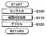
先ず、センサエレメント713の各セルの検出出力が入力され(S100)、各セルの検出出力に基づき、次のようにフロント窓ガラス100が結露しているか否かを判定する(S110)。
【0052】
先ず、センサエレメント713には、各座席を含む所望領域からの赤外線が入射される為、通常、所望領域には不均一の温度分布が形成され、センサエレメント713のセル毎の出力は、不均一になる。
【0053】
しかし、フロント窓ガラス100が結露している場合には、フィルタ714は、フロント窓ガラス100に対して、熱結合部材110、筐体710を介して熱的に結合されているため、フィルタ714の温度としては、フロント窓ガラス100の温度と同等になる。すなわち、フィルタ714の温度としても、結露の発生する温度になり、フィルタ714が結露した状態では、センサエレメント713には各座標を含む所定領域からの赤外線ではなく、結露水温度に応じた赤外線が入射されるため、センサエレメント713としては、各セルの出力がほぼ均一になる。このため、センサエレメント713の各セルの出力が、所定範囲内に入っているときには、フロント窓ガラス100に結露が発生していることを判定(推定)する。
【0054】
すなわち、センサエレメント713の検出に基づき、各セルの検出温度分布が所定範囲内に入っているときには、フロント窓ガラス100に結露が発生していることを判定して、フロント窓ガラス100の結露を止めるために、吹出モードとしてデフロスタモードを選択する(S120)。これに伴い、冷凍サイクルによって除湿された空気をフロント窓ガラス100に向けて吹き出して、フロント窓ガラス100の曇りを除去する。
【0055】
(他の実施形態)
上記実施形態では、フロント窓ガラス100の結露を止めるために、冷凍サイクルによって除湿された空気をフロント窓ガラス100に向けて吹き出す例について説明したが、フロント窓ガラス100を透明導電性薄膜(電熱線)を用いて加熱するようにしてもよい。すなわち、フロント窓ガラス100の内壁に透明導電性薄膜を沿わしておき、車載バッテリから透明導電性薄膜に通電させて、透明導電性薄膜によりフロント窓ガラス100を加熱させるようにしてもよい。
【0056】
上記実施形態では、センサエレメント713として、センサ自身の絶対温度を検出する温度センサ(温度検出手段)を含んでいるものを示したが、この温度センサにより、フロント窓ガラス100の内壁の近傍の温度を検出し、この検出温度と、湿度センサ77により検出された車室内空気の相対湿度とに基づき、フロント窓ガラス100に結露が発生しているか否かを判定するようにしてもよい。
【0057】
上記実施形態では、ウインドシールドとして、フロント窓ガラス100を適用した例について説明したが、側方窓ガラスや後方窓ガラスを用いるようにしてもよい。
【0058】
上記実施形態では、センサエレメント713の検出に基づき、所望領域における温度分布が所定範囲内に入っていることの判定を一回行ったとき、フロント窓ガラス100が結露していることを判定したが、所望領域における温度分布が所定範囲内に入っていることの判定を複数回行ったとき、フロント窓ガラス100が結露していることを判定するようにしてもよい。
【0059】
上記実施形態において、センサエレメント713の各セルのうち、いずれか1つのセルの検出温度が所定範囲内から外れたとき、デフロスタモードを停止して、ウインドシールドの曇りの除去を停止する。
【0060】
上記実施形態において、センサエレメント713の検出に基づき、フロント窓ガラス100の結露度合い(すなわち、曇り度合い)を推定するようにしてもよい。
【0061】
例えば、センサエレメント713の各セルのうち、検出温度が所定範囲内に入っているセルの数により、ウインドシールドの結露度合を推定する。そして、透明導電性薄膜によりフロント窓ガラス100を加熱させる場合、検出温度が所定範囲内に入っているセルの数が多くなるについて、透明導電性薄膜に流す電流を増やして発熱量を上げたり、電流を流す時間を長くするようにしてもよい。
【0062】
さらに、各セルのうち少なくとも1つのセルの検出温度が所定範囲内に入ってから各セルの全ての検出温度が所定範囲内に入るまでの時間を計測し、この計測された時間に基づき、ウインドシールドの結露度合いを推定するようにしてもよい。この場合、計測時間が短いほど、結露度合い(曇り度合い)が大きいとして、透明導電性薄膜に流す電流を増やして発熱量を上げたり、電流を流す時間を長くするようにしてもよい。
【0063】
上記実施形態において、フロント窓ガラス100の結露を止めるために、吹出モードとしてデフロスタモードを選択した例について選択したが、フットデフモードを選択するようにしてもよい。
【0064】
上記実施形態において、車両用温度センサとして、サーモパイル式のセンサをを用いた例を示したが、これに限らず、パイロ、サーミスタボロメータ、ゴーレイセルなどの各種のタイプの赤外線センサを用いることができる。また、車室内の各エリアの温度を個々に検出するもので、窓ガラスの内壁とを熱的に結合できるものであれば、赤外線検出の温度センサ以外のセンサを用いるようにしてもよい。
【0065】
上記実施形態において、32個のセルを有するセンサエレメント713を筐体710内に配設して赤外線センサ71を構成するようにした例を示したが、図6に示すように、単一のセルを筐体710内に配設して構成されるセンサ本体71bを複数個(図では、2個の例を示す)用い、これらセンサ本体71bと熱結合部材110とにより赤外線センサを構成するようにしてもよい。
【図面の簡単な説明】
【図1】本発明の第1実施形態に係る車両用温度検出装置を適用した車両用空調装置の全体構成図である。
【図2】赤外線センサの取る付け構造を示す断面図である。
【図3】赤外線センサの構造を示す断面図である。
【図4】赤外線センサのセンサエレメントを示す図である。
【図5】マイクロコンピュータの作動を示すフローチャートである。
【図6】変形例の赤外線センサの構造を示す断面図である。
【符号の説明】
71…赤外線センサ、71a…センサ本体、100…フロント窓ガラス、
110…熱結合部材、111…開口部、713…センサエレメント、
710…筐体。[0001]
BACKGROUND OF THE INVENTION
The presentinvention, condensation estimation method, a safety device fogging vehicle.
[0002]
[Background Art and Problems to be Solved by the Invention]
Conventionally, in order to detect dew condensation on the windshield of a vehicle, a sensor has been devised that detects the humidity near the windshield using a change in electrical resistance (or a change in capacitance).
[0003]
However, there is a problem that such a sensor requires a dedicated sensor only for detecting dew condensation on the windshield, which increases costs. Therefore, the present inventor detects the condensation of the windshield using a known IR sensor (Japanese Patent Laid-Open No. 2001-150920, Japanese Patent Laid-Open No. 10-160580) proposed for detecting the temperature distribution in the passenger compartment. It was investigatedto.
[0004]
Therefore, an object of the present invention is to provide a vehicle anti-fogging device and a dew condensation estimation method usingdetection means forindividually detectingthe temperature ofeach area in a vehicle interior.
[0005]
[Means for Solving the Problems]
In order to achieve the above object, in the invention according to
A coupling member (110) for thermally coupling the detection means and the inner wall of the windshield of the vehicle;
First determination means (S110) for determining whether the temperature distribution of each area is within a predetermined range in response to detection by the detection means;
When the first determination means determines that the temperature distribution of each area is within a predetermined range, it is determined that the windshield has dewed, and the removal means for removing fog on the windshield (S120). It is characterized by having.
[0011]
Here, as in the invention described in
[0012]
Thereby, it is possible to accurately determine whether or not the windshield is condensed.
[0013]
Further, as in thethird aspect of the invention, the second determination means for determining whether or not the detected temperature of at least one of the areas is out of the predetermined range in response to detection by the detection means. And a stopping means for stopping the removal of fogging of the windshield when the second determining means determines that the detected temperature of at least one of the areas is out of the predetermined range. Also good.
[0014]
Further, as in the invention described in
[0015]
Here, as in the invention described in
[0016]
Further, as the removing means, as in thesixth aspect of the invention, it may be configured such that blown air for removing the fog of the windshield is blown out to the inner wall of the windshield. Further, the removing means may be configured to have a heating wire that generates heat by energization in order to heat the windshield, as in the invention described in claim7 .
[0018]
In the invention described in請 Motomeko8, it is an inner wall and thermally coupled windshield of the vehicle, and using the detection means (71a) for detecting the temperature of each area in the vehicle compartment individually windshield condensation A dew condensation estimation method for estimating occurrence, wherein whether or not the temperature distribution of each area is within a predetermined range is determined according to detection by the detection means, and the detected temperature distribution is within the predetermined range. When it is determined that there is condensation, it is estimated that condensation has occurred on the inner wall of the windshield.
[0019]
In the invention according to claim9 , the temperature of each area is detected by using detection means (71a) which is thermally coupled to the inner wall of the windshield of the vehicle and individually detects the temperature of each area in the passenger compartment. The distribution is detected, and the degree of condensation on the windshield is estimated according to the detected temperature distribution.
[0020]
In addition, the code | symbol in the bracket | parenthesis of each said means shows a corresponding relationship with the specific means as described in one Embodiment mentioned later.
[0021]
DETAILED DESCRIPTION OF THE INVENTION
FIG. 1 is an overall configuration diagram of a vehicle air conditioner using a vehicle temperature detection device according to an embodiment of the present invention, and an
[0022]
A blower 7 is arranged on the downstream side of the air flow in the inside / outside
[0023]
An
[0024]
The
[0025]
In the
[0026]
Between the
[0027]
A
[0028]
The
[0029]
Each of the
[0030]
That is, in the face mode, the
[0031]
In the bi-level mode, both the
[0032]
In the foot mode, the
[0033]
In the foot defroster mode, the
[0034]
In the defroster mode, the
[0035]
Next, the outline of the electric control unit in the present embodiment will be described. The air conditioning
[0036]
Detection signals are input from the
[0037]
Further, the air
[0038]
As switches of the air
[0039]
Next, the
[0040]
The sensor
[0041]
The
[0042]
Further, the
[0043]
Here, the
[0044]
By the way, the temperature of the part where the surface is exposed in the driver's seat, that is, the part not covered by the driver is correlated with the temperature in the passenger compartment, so the signal of the cell where the infrared rays from the surface of the driver's seat are incident The temperature in the passenger compartment can be estimated based on the above.
[0045]
Next, the operation of the
[0046]
When the
[0047]
First, based on the set temperature, the temperature of the driver and its surroundings, the temperature of the front window glass 94, the outside air temperature, the amount of solar radiation, and the like, the target blowing temperature of the blown air blown into the passenger compartment is calculated. This target blowing temperature is the temperature of the blowing air necessary for maintaining the temperature in the passenger compartment at the set temperature.
[0048]
Next, the target opening degree of the
[0049]
Next, the target air volume of the air blown by the blower 7 is calculated based on the target blowing temperature, and the blower voltage for realizing the target air volume is determined. Next, the inside / outside air mode is determined according to the target blowing temperature, the blowing mode is determined based on the target blowing temperature and the relative humidity of the cabin air, and the operation / stop of the
[0050]
Here, for example, an example in which the defroster mode is selected as the blowing mode will be described.
[0051]
First, the detection output of each cell of the
[0052]
First, since infrared rays from a desired area including each seat are incident on the
[0053]
However, when the
[0054]
That is, based on the detection of the
[0055]
(Other embodiments)
In the above embodiment, an example in which air dehumidified by the refrigeration cycle is blown out toward the
[0056]
In the above embodiment, the
[0057]
In the above embodiment, an example in which the
[0058]
In the above embodiment, based on the detection of the
[0059]
In the above embodiment, when the detected temperature of any one of the cells of the
[0060]
In the embodiment described above, the degree of condensation (that is, the degree of fogging) of the
[0061]
For example, the degree of condensation of the windshield is estimated based on the number of cells in which the detected temperature is within a predetermined range among the cells of the
[0062]
Further, the time from when the detected temperature of at least one of the cells falls within a predetermined range until all the detected temperatures of each cell fall within the predetermined range is measured, and the window is calculated based on the measured time. The degree of condensation on the shield may be estimated. In this case, the shorter the measurement time, the greater the degree of condensation (the degree of clouding), so that the amount of heat generated by increasing the current flowing through the transparent conductive thin film may be increased, or the time for flowing the current may be lengthened.
[0063]
In the said embodiment, in order to stop dew condensation of the
[0064]
In the above-described embodiment, an example in which a thermopile sensor is used as the vehicle temperature sensor is shown. However, the present invention is not limited to this, and various types of infrared sensors such as a pyro, thermistor bolometer, and go-ray cell can be used. Also, a sensor other than the temperature sensor for detecting infrared rays may be used as long as it can individually detect the temperature of each area in the passenger compartment and can be thermally coupled to the inner wall of the window glass.
[0065]
In the above embodiment, an example in which the
[Brief description of the drawings]
FIG. 1 is an overall configuration diagram of a vehicle air conditioner to which a vehicle temperature detection device according to a first embodiment of the present invention is applied.
FIG. 2 is a cross-sectional view showing a mounting structure of an infrared sensor.
FIG. 3 is a cross-sectional view showing the structure of an infrared sensor.
FIG. 4 is a diagram showing a sensor element of an infrared sensor.
FIG. 5 is a flowchart showing the operation of the microcomputer.
FIG. 6 is a cross-sectional view showing the structure of a modified infrared sensor.
[Explanation of symbols]
71 ... Infrared sensor, 71a ... Sensor body, 100 ... Front window glass,
110 ... thermal coupling member, 111 ... opening, 713 ... sensor element,
710: A housing.
Claims (9)
Translated fromJapanese前記検出手段と車両のウインドシールドの内壁とを熱的に結合する結合部材(110)と、
前記検出手段の検出に応じて、前記各エリアの温度分布が所定範囲内に入っているか否かを判定する第1の判定手段(S110)と、
前記各エリアの温度分布が所定範囲内に入っていることを前記第1の判定手段が判定したとき、前記ウインドシールドが結露しているとして、前記ウインドシールドの曇りを除去する除去手段(S120)と、を有することを特徴とする車両用曇り止め装置。Detection means (71a) for individually detecting the temperature of each area in the passenger compartment;
A coupling member (110) for thermally coupling the detection means and the inner wall of the windshield of the vehicle;
First determination means (S110) for determining whether the temperature distribution of each area is within a predetermined range in response to detection by the detection means;
When the first determination means determines that the temperature distribution of each area is within a predetermined range, it is determined that the windshield has dewed, and the removal means for removing fog on the windshield (S120). And an anti-fogging device for vehicles.
前記各エリアのうち少なくとも1つのエリアの検出温度が前記所定範囲内から外れたことを前記第2の判定手段が判定したとき、前記ウインドシールドの曇りの除去を停止する停止手段と、を有することを特徴とする請求項1又は2に記載の車両用曇り止め装置。Second determination means for determining whether or not the detected temperature of at least one of the areas is out of the predetermined range in response to detection by the detection means;
Stop means for stopping removal of fogging of the windshield when the second determination means determines that the detected temperature of at least one of the areas is out of the predetermined range. The anti-fogging device for vehicles according to claim1 or 2 .
前記検出手段と車両のウインドシールドの内壁とを熱的に結合する結合部材(110)と、
前記検出手段の検出に応じて、前記ウインドシールドの結露度合いを推定する推定手段と、
前記推定されたウインドシールド結露度合いに応じて、前記ウインドシールドの曇りを除去する除去手段と、を有することを特徴とする車両用曇り止め装置。Detection means (71a) for individually detecting the temperature of each area in the passenger compartment;
A coupling member (110) for thermally coupling the detection means and the inner wall of the windshield of the vehicle;
Estimating means for estimating the degree of condensation of the windshield in response to detection by the detecting means;
An anti-fogging device for a vehicle, comprising: a removing unit that removes fogging of the windshield according to the estimated degree of windshield condensation.
前記検出手段の検出に応じて、前記各エリアの温度分布が所定範囲内に入っているか否かを判定し、
前記検出された温度分布が所定範囲内に入っていることが判定されたとき、前記ウインドシールドの内壁に結露が発生していることを推定することを特徴とする結露推定方法。This is a dew condensation estimation method for estimating the occurrence of dew condensation on the windshield using detection means (71a) that is thermally coupled to the inner wall of the windshield of the vehicle and individually detects the temperature of each area in the vehicle interior. And
In response to detection by the detection means, it is determined whether the temperature distribution of each area is within a predetermined range,
When it is determined that the detected temperature distribution falls within a predetermined range, it is estimated that condensation has occurred on the inner wall of the windshield.
前記検出された温度分布に応じて、前記ウインドシールドの結露度合いを推定することを特徴とする結露推定方法。The temperature distribution of each area is detected using detection means (71a) that is thermally coupled to the inner wall of the windshield of the vehicle and individually detects the temperature of each area in the passenger compartment.
A dew condensation estimation method, wherein the dew condensation degree of the windshield is estimated according to the detected temperature distribution.
Priority Applications (1)
| Application Number | Priority Date | Filing Date | Title |
|---|---|---|---|
| JP2002227720AJP4082124B2 (en) | 2002-08-05 | 2002-08-05 | Anti-fogging device for vehicle and method for estimating condensation |
Applications Claiming Priority (1)
| Application Number | Priority Date | Filing Date | Title |
|---|---|---|---|
| JP2002227720AJP4082124B2 (en) | 2002-08-05 | 2002-08-05 | Anti-fogging device for vehicle and method for estimating condensation |
Publications (2)
| Publication Number | Publication Date |
|---|---|
| JP2004066927A JP2004066927A (en) | 2004-03-04 |
| JP4082124B2true JP4082124B2 (en) | 2008-04-30 |
Family
ID=32014666
Family Applications (1)
| Application Number | Title | Priority Date | Filing Date |
|---|---|---|---|
| JP2002227720AExpired - Fee RelatedJP4082124B2 (en) | 2002-08-05 | 2002-08-05 | Anti-fogging device for vehicle and method for estimating condensation |
Country Status (1)
| Country | Link |
|---|---|
| JP (1) | JP4082124B2 (en) |
Families Citing this family (6)
| Publication number | Priority date | Publication date | Assignee | Title |
|---|---|---|---|---|
| US7360416B2 (en) | 2005-07-07 | 2008-04-22 | Ricoh Company, Ltd. | Non-contact condensation detecting apparatus |
| JP4816212B2 (en) | 2006-04-10 | 2011-11-16 | 日産自動車株式会社 | Glass temperature detection device, window fogging detection device, vehicle air conditioner, and window fogging detection method |
| JP5895235B2 (en)* | 2011-10-07 | 2016-03-30 | パナソニックIpマネジメント株式会社 | machine |
| JP6702206B2 (en)* | 2017-01-23 | 2020-05-27 | 株式会社デンソー | Vehicle air conditioner |
| JP6933722B2 (en)* | 2017-09-26 | 2021-09-08 | 旭化成株式会社 | Anti-fog device |
| CN114113216B (en)* | 2020-08-26 | 2023-10-13 | 宝山钢铁股份有限公司 | Dew-condensation early warning method for coiled warehouse with steel plates |
- 2002
- 2002-08-05JPJP2002227720Apatent/JP4082124B2/ennot_activeExpired - Fee Related
Also Published As
| Publication number | Publication date |
|---|---|
| JP2004066927A (en) | 2004-03-04 |
Similar Documents
| Publication | Publication Date | Title |
|---|---|---|
| JPH09175143A (en) | Air conditioning device for vehicle | |
| JP2001191779A (en) | Air conditioner for vehicle | |
| JP2008094380A (en) | Humidity detector and vehicular air conditioner | |
| JP4114651B2 (en) | Air conditioner for vehicles | |
| JPH09123734A (en) | Vehicular air-conditioner | |
| US7222666B2 (en) | Vehicle air-conditioning apparatus that can surely defog window | |
| JP3843962B2 (en) | Air conditioner for vehicles | |
| JP4682930B2 (en) | Air conditioner for vehicles | |
| JP4784573B2 (en) | TECHNICAL FIELD The present invention relates to a vehicle air conditioner. | |
| JP4082124B2 (en) | Anti-fogging device for vehicle and method for estimating condensation | |
| JP4310902B2 (en) | Air conditioner for vehicles | |
| JP3812412B2 (en) | Air conditioner for vehicles | |
| JP4915212B2 (en) | Air conditioner for vehicles | |
| JP4327498B2 (en) | Air conditioner for vehicles | |
| JP2004276857A (en) | Windowpane defogging system for vehicle | |
| JP3149686B2 (en) | Vehicle air conditioner | |
| JP2003326938A (en) | Air-conditioning defogging control device for vehicle | |
| JP4281212B2 (en) | Air conditioner for vehicles | |
| JP3755221B2 (en) | Air conditioner for vehicles | |
| JP2003080920A (en) | Vehicular air conditioner | |
| JP3169063B2 (en) | Vehicle air conditioner | |
| JP3861805B2 (en) | Air conditioner for vehicles | |
| JP3832351B2 (en) | Air-conditioning anti-fogging control device for vehicles | |
| JP4123687B2 (en) | Air conditioner for vehicles | |
| JP3467111B2 (en) | Electric vehicle air conditioner |
Legal Events
| Date | Code | Title | Description |
|---|---|---|---|
| A621 | Written request for application examination | Free format text:JAPANESE INTERMEDIATE CODE: A621 Effective date:20040914 | |
| A131 | Notification of reasons for refusal | Free format text:JAPANESE INTERMEDIATE CODE: A131 Effective date:20070703 | |
| A521 | Written amendment | Free format text:JAPANESE INTERMEDIATE CODE: A523 Effective date:20070829 | |
| TRDD | Decision of grant or rejection written | ||
| A01 | Written decision to grant a patent or to grant a registration (utility model) | Free format text:JAPANESE INTERMEDIATE CODE: A01 Effective date:20080122 | |
| A61 | First payment of annual fees (during grant procedure) | Free format text:JAPANESE INTERMEDIATE CODE: A61 Effective date:20080204 | |
| R150 | Certificate of patent or registration of utility model | Free format text:JAPANESE INTERMEDIATE CODE: R150 | |
| FPAY | Renewal fee payment (event date is renewal date of database) | Free format text:PAYMENT UNTIL: 20110222 Year of fee payment:3 | |
| LAPS | Cancellation because of no payment of annual fees |