JP4081917B2 - Electronic camera device and strobe color correction method - Google Patents
Electronic camera device and strobe color correction methodDownload PDFInfo
- Publication number
- JP4081917B2 JP4081917B2JP11934799AJP11934799AJP4081917B2JP 4081917 B2JP4081917 B2JP 4081917B2JP 11934799 AJP11934799 AJP 11934799AJP 11934799 AJP11934799 AJP 11934799AJP 4081917 B2JP4081917 B2JP 4081917B2
- Authority
- JP
- Japan
- Prior art keywords
- image
- strobe
- luminance
- imaging
- color correction
- Prior art date
- Legal status (The legal status is an assumption and is not a legal conclusion. Google has not performed a legal analysis and makes no representation as to the accuracy of the status listed.)
- Expired - Fee Related
Links
Images


Landscapes
- Color Television Image Signal Generators (AREA)
- Studio Devices (AREA)
- Exposure Control For Cameras (AREA)
- Stroboscope Apparatuses (AREA)
Description
Translated fromJapanese【0001】
【発明の属する技術分野】
本発明はデジタルカメラ等の電子カメラ装置に関し、特に、ストロボ撮像画像の補正技術に関する。
【0002】
【従来の技術】
従来、光量の足りない場所での撮像は、光学カメラ(銀塩カメラ)では露光時間を長くして撮像するか、或いはストロボを発光させることで光量を補って撮像を行なっている。後者の場合、ストロボを用いると露光時間を短くできるので、暗所でもカメラを固定することなく撮像できる。
【0003】
一方、デジタルカメラ等の電子カメラ装置では、暗所(光量が不足している場所をいう)ではCCDの感度を上げて(CCDからの信号を増幅して)明るい画像を撮像する手法が用いられているが、光量の足りない場所で撮像するために撮像素子の感度を上げ過ぎると撮像された画像に電気的なノイズ成分が目立つようになり良好な画像が得られないという問題点があるので、ある程度以上暗いところでは電子カメラ装置での撮像の際ストロボを用いて光量を補い、撮像できるように構成されたものがある。
【0004】
このような電子カメラ装置ではストロボ撮像を行うと撮像画像にストロボ光の色合いが加わり、不自然になるのでストロボ撮像の際ストロボ光の持つ色合いを打ち消して自然な色合いとする目的で一定の補正量を撮像画像全体に施していた。
【0005】
【発明が解決しようとする課題】
しかしながら、上記従来のストロボ色補正方法では一定の補正量を画像全体一律に施すためにストロボ撮像された画像中でストロボ光の影響が少ない部分では色補正が過多となり、補正によってかえって不自然な色になってしまうといった問題点があった。例えば、図5(a)に示すように比較的明るい室内で白い壁53を背景に人物51をストロボ撮影した場合、ストロボ光がちゃんとあたる人物51は色補正によって自然な色合いに撮れるが、背景の白い壁53や人物51より後にある物体52はストロボ光のあたる程度が少ないので人物51と同様の色補正(図5(b))を行うと図5(c)に示すような不自然な色合いとなる(背景が白い壁53の場合は黄ばんだ色となる。また、物体52についても色合いが不自然になる)といった問題点があった。
【0006】
本発明は、上記従来技術の問題点および解決課題に基づいてなされたものであり、ストロボ撮像時に自然な色合の画像を得ることのできる電子カメラ装置およびストロボ色補正方法の提供を目的とする。
【0007】
【課題を解決するための手段】
上記の目的を達成するために、第1の発明の電子カメラ装置は、ストロボ撮像が可能な電子カメラ装置において、スルー画像を得るとともに、ストロボ撮像指示によりストロボ撮像画像を得る撮像手段と、この撮像手段により得られるスルー画像を表示する表示手段と、前記撮像手段により得られるスルー画像の輝度とストロボ撮像画像の輝度を抽出する輝度抽出手段と、この輝度抽出手段により抽出されたスルー画像の輝度とストロボ撮像画像の輝度とを比較して輝度差分布を得る画像比較手段と、この画像比較手段により得られた輝度差に比例した補正量で前記撮像手段により得られるストロボ撮像画像の色補正を行うことにより、ストロボ撮像画像に含まれるストロボ光のもつ色合いを打ち消すストロボ撮像画像補正手段と、を備えたことを特徴とする。
また、第2の発明は上記第1の発明の電子カメラ装置において、前記画像比較手段は前記スルー画像と前記ストロボ撮像画像の複数部分の輝度を比較して各部分の輝度差を得る手段を含み、前記ストロボ撮像画像補正手段は前記各部分の輝度差に比例した複数の補正量で前記ストロボ撮像画像の複数部分の色補正を行うことを特徴とする。
【0009】
また、第3の発明は上記第1又は第2の発明の電子カメラ装置において、前記画像比較手段は、前記ストロボ撮像画像の直前または直後に前記撮像手段により得られるスルー画像の輝度とストロボ撮像画像の輝度を比較して輝度差分布を得ることを特徴とする。
【0010】
また、第4の発明は上記第1乃至第3のいずれかの発明の電子カメラ装置において、ストロボ撮像画像補正手段により色補正されたストロボ撮像画像を記録する記録手段を備えたことを特徴とする。
【0013】
また、第5の発明のストロボ色補正方法は、ストロボ撮像が可能な電子カメラ装置において、スルー画像とストロボ撮像画像を得て、該スルー画像の輝度とストロボ撮像画像の輝度を抽出し、該スルー画像の輝度とストロボ撮像画像の輝度を比較して輝度差分布を取得し、この輝度差に比例した補正量でストロボ撮像画像のストロボ色補正を行い、このストロボ色補正画像を記録することを特徴とする。
【0014】
【発明の実施の形態】
[回路構成例]
図1は、本発明を適用した電子カメラ装置の一実施例としてのデジタルカメラの回路構成例を示すブロック図であり、図1(a)で、デジタルカメラ100は、光学系10、ストロボ発光部11、信号変換部12、信号処理部13、DRAM14、制御部20、操作部30、表示部40、保存記録メモリ(メモリーカード)50を有している。
【0015】
光学系10は、撮像レンズ101と光量検出部102および合焦機構(図示せず)から構成され、撮像レンズ101を介して集光された被写体像の光束を後段のCCD(撮像素子)121上に結像させる。
【0016】
ストロボ発光部11は、制御部20からシャッター押下げ信号を受け取ると極めて短い時間内に所定の光量を放出(発光)し、周辺の光量を補う。
【0017】
信号変換部12は、CCD121、CCD駆動用タイミング信号生成回路(TG)122,CCD駆動用垂直ドライバ123,自動利得制御回路(AGC)124およびA/D変換器125を含み、前段の光学系10を介してCCD121に結像した画像を電気信号に変換し、デジタルデータ(以下、画像データ)に変換して一定の周期で出力する。AGC124はストロボ設定がされているか周辺光量が閾値(φmin〜φmax)の下限以上の場合にはCCD121からの信号の増幅率を所定値に保つが、ストロボ設定がされておらず且つ周辺光量が適正閾値(φmin〜φmax)の下限φminより低い場合にはCPUの制御によりCCD121からの信号がAGC124により増幅されてA/D変換器に与えられ、増幅の結果を制御部20で光量に変換して閾値と比較し、比較結果はAGC124にフィードバックされる。これによりCCD121からの信号は光量が適正閾値内になるまで増幅される。
【0018】
信号処理部13は図1(b)に示すようにカラープロセス回路131およびDMAコントローラ132を有し、信号変換部12からの出力をカラープロセス処理してデジタルの輝度、色差マルチプレクス信号(YUVデータ)とし、YUVデータをDRAM14の指定領域にDMA(ダイレクトメモリーアクセス)転送する。
【0019】
制御部20は、CPU、RAM、プログラム格納用ROMを備えたマイクロプロセッサ構成を有しており、CPUは上述の各回路等にバスラインを介して接続し、プログラム格納用ROMに格納されている制御プログラムによりデジタルカメラ100全体の制御を行なうと共に、操作部30からの状態信号に対応してデジタルカメラ100の各機能の実行制御等を行なう。また、プログラム格納用ROMはPROMやFROM(フラッシュROM)等が用いられる、制御プログラムやデジタルカメラの各処理モード用の処理プログラムの他、ストロボ色補正プログラムが格納されている。また、RAMの代りとしてDRAM14に割当てられた領域を用いるようにしてもよい。
【0020】
操作部30は、図2に示すようにシャッターボタン35およびストロボ設定ボタン36のほか、図示しない主電源スイッチ、RECモード/再生モード切換えスイッチ、機能選択用ボタン、カーソル移動キー等のキーを構成部分としたデジタルカメラ100の操作入力手段であり、これらのキーが操作されると操作されたキーの状態に対応する状態信号が制御部20に送出される。また、プラス・マイナス(+・−)キー37に色調整キーとしての機能を割り付けてもよい。
【0021】
表示部40はVRAM(Video Random Access Memory)及び液晶画面等の表示装置から構成されており、撮像時に液晶画面に被写体画像(スルー画像)が表示されるので、液晶画面をファインダとして用いることができる。また、再生モード時には再生画像を表示できる。
【0022】
保存記録用メモリ50はフラッシュメモリー等のリムーバブルな記録媒体からなり、画像データや画像情報を記録する。なお、実施例では保存記録メモリ50としてデジタルカメラ100の本体に着脱自在なメモリーカードを用いたが、これに限定されない。
【0023】
[装置外観例]
図2は、図1のデジタルカメラ100の概観図であり、(a)は正面図、(b)は背面図である。デジタルカメラ100の正面には(a)に示すようにストロボ発光部11、撮像レンズ101及び光量検出部102が設けられている。また、背面には(b)に示すように表示部40の液晶画面及びストロボ表示ランプ111のほか、主電源スイッチ及びRECモード/再生モード切換えスイッチ等(図示せず)が設けられている。また、上面には、シャッターボタン35、ストロボ設定ボタン36および色調整ボタン37のほか機能選択用ボタン等のキー(図示せず)が設けられている。なお、ストロボ表示ランプ111はLED等で構成され、実施例では赤および緑の2種類の発光表示(点灯)が可能である。
【0024】
[DRAM14の領域設定例]
図3は、図1のデジタルカメラ100の回路構成を例としたDRAM14内の各バッファ等の領域設定例を示す説明図である。本実施例では信号処理部13からの画像データ、VRAMへの画像データの出力およびデータ圧縮/伸張の際の画像データの書込/読み出しに同じDRAM14を用いている。このためにDRAM14上の画像データ記録用の領域の構成として、図3に示すようにいくつかの領域に分割したバッファを用意することで、目的に応じて各領域を設定できる。また、図3で記号141はスルー画像バッファを、142はストロボ撮像直前(或いは直後)のスルー画像を記憶する画像バッファ、143はストロボ撮像により取り込まれるストロボ撮像画像を記憶するバッファ(以下、ストロボ画像バッファ)を、144は色補正後の画像を記憶する色補正画像バッファを、145は撮像直前(あるいは直後)の輝度分布データ、ストロボ撮像時の輝度分布データ及びその差分等や定数等を記録する予備領域、146はワークエリア(作業用エリア)を示す。なお、図3の例では画像バッファ142を設けたが設けなくてもよい(図7)。また、色補正画像バッファ144を設けることなくストロボ画像バッファ143と色補正画像バッファ144を同一の画像バッファとしてもよい。
【0025】
[輝度分布の例]
図4は、図5(a)に示す2つの被写体51,52と背景(白い壁)53を含む画像の輝度分布の説明図であり、図5はストロボ撮影及びストロボ色補正処理による撮像画像の説明図である。また、図4(a)は図5(a)の被写体のスルー画像の実際の輝度分布を示し、図4(b)は図5(a)の人物51に合焦してストロボ撮像を行なった結果のX方向の輝度分布を示し、図4(c)は図4(b)の輝度分布から図4(a)の輝度分布を差し引いた差分の分布を示し、図4(d)は図4(c)の差分をその大きさにより1〜3のランクk1、k2、k3にランク付けして示した分布図である。なお、図4の例ではX方向の輝度分布のみを示したが、実施例ではY方向の輝度分布も同様に取得する(図6、図7)。
【0026】
また、図5(a)はスルー画像の例を示す図であり、(b)、(c)は従来のストロボ色補正方法およびその結果の説明図である。また、(b’)、(c’)は本発明のストロボ色補正およびその結果の説明図である。
【0027】
[ストロボ色補正方法]
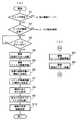
▲1▼本発明のストロボ色補正方法の一実施例では、図6のフローチャートのステップS6〜S9に示すように、1シャッター動作で、ストロボ撮像直前(あるいは直後)のスルー画像の撮像とストロボ撮像画像の撮像を行いそれぞれの撮像画像から輝度を取り出してそれらの差分(図4(c))の分布を得てから、輝度の差分の分布に比例する補正量を付加してストロボ光のもつ色合いを打ち消す処理を行う。
▲2▼また、他の実施例として、図7のフローチャートのステップT3、T5〜T8(又はT3’〜T8)に示すように、ストロボ撮像直前(あるいは撮像直後)のスルー画像の輝度分布を取得して保持(一時記憶)すると共に、ストロボ撮像画像の輝度分布を取得し、両者の輝度分布の差分の分布を得てから、輝度の差分の分布に比例する補正量を付加してストロボ光のもつ色合いを打ち消す処理を行う。
▲3▼また、他の実施例として、図8に示すように図6又は図7のストロボ色補正方法で得た輝度の差分の分布を2又は3程度に分類してランク付けし、ランクの同じ部分ごとに対応するストロボ色補正を施し、ユーザが再生画像を見て色合いを修正できるようにする。
なお、上述した3つの実施例において、スルー画像の輝度とストロボ撮像画像の輝度を比較してその差が所定の範囲内の部分にはストロボ色補正を行わないようにしてもよい。
【0028】
[動作例1]
図6はストロボ撮像モード下でのデジタルカメラの動作の一例を示すフローチャートである。また、図6で、(a)はストロボ撮像直前のスルー画像を比較対象とする例であり、ステップS6〜S9がストロボ光補正処理に相当する。また、(b)はストロボ撮像直後のスルー画像を比較対象とする例である。
【0029】
ステップS1:(ストロボ設定の有無判定)
図6で、撮像モードが選択されるとスルー画像が表示部40に表示される。ここで、ユーザは周辺の明るさか表示部40の液晶画面の明るさのいずれかからストロボ撮影が必要と判断した場合にはストロボ設定ボタン36を押す。
【0030】
撮像モードが選択されると制御部20は操作部30からの状態信号を調べてストロボ設定ボタン36が押されたか否かを判定し、ストロボ設定ボタン36が押された場合にはストロボ発光部11への電荷印加を開始すると共にストロボ表示ランプ111を点灯してS2に遷移し、そうでない場合には他の撮像モードに遷移する。ストロボ表示ランプ111はストロボ充電状態では赤、ストロボ発光可能状態では青色に点灯する。
【0031】
ステップS2:(ストロボ撮像の可否判定)
次に、制御部20は光量検出部102からの検出光量Lと撮像に必要とする光量(閾値φ)を比較し、L<φの場合にはS3に移行する。また、L≧φの場合にはストロボ撮像不要としてストロボ設定を解除しストロボ表示ランプ111による発光表示を中止すると共に、ストロボ発光部11への電荷印加を中止して通常の撮像モードに遷移する。
【0032】
ステップS3:(撮像指示)
ストロボが発光可能状態になった以降の任意のタイミングでユーザーがシャッターボタン35を押すと、制御部20はAGC124に対してゲインを通常値(実際の光量による値)にするための制御信号を送出すると共に、ストロボ発光部11に発光指示信号を与える。
【0033】
ステップS4:(撮像:直前のスルー画像)
制御部20は、また、ストロボ発光直前のスルー画像バッファ141に取り込まれている画像(直前のスルー画像)を画像バッファ142に記憶すると共に、CCD121から取込む画像データのDRAM14上の記憶領域をストロボ画像バッファ143に切換えてS5に遷移する。
【0034】
ステップS5:(撮像:ストロボ撮像画像)
上記ステップS3、S4の動作後に、CCD121からの信号の増幅率が通常値に戻され、ストロボが発光して発光量Pだけ周囲の光量を補う。CCD121からの信号はストロボ発光により補われた光量Pを加えた分増加する。また、ストロボ画像バッファ143にはストロボ撮像画像が取り込まれて記憶される。また、制御部20はCCD121から取込むデータのDRAM14上の記憶領域をスルー画像バッファ141に切換える。
【0035】
ステップS6:(スルー画像の輝度分布の取得)
次に、制御部20は画像バッファ142に記憶された撮像画像のX方向(図4(a))およびY方向の輝度分布を取得(抽出)してDRAM14の予備領域145の所定領域に記憶(上書き)する。
【0036】
ステップS7:(ストロボ撮像画像の輝度分布取得)
制御部20はCCD121からストロボ画像バッファ143に取込まれたストロボ撮像画像のX方向(図4(b))およびY方向の輝度分布を取得してDRAM14の予備領域145の所定領域(スルー画像の輝度分布の記憶領域とは別の場所)に記憶(上書き)する。
【0037】
ステップS8:(輝度分布の差分の取得)
制御部20は上記ステップS6で得たストロボ発光直前の撮像画像の輝度分布値からステップS7で得たストロボ撮像画像の輝度分布値をそれぞれ差し引いてX方向(図4(c))およびY方向の差分の分布を取得してDRAM14の予備領域145の所定領域(ストロボ発光直前の撮像画像やストロボ撮像画像の輝度分布の記憶領域とは別の場所)に記憶する。
【0038】
ステップS9:(差分に比例させたストロボ色補正)
制御部20はストロボ光のもつ色合いを打ち消すための補正色を上記ステップS6で得たX方向およびY方向の輝度の差分に比例するようにストロボ画像バッファ143に記憶されているストロボ撮像画像に合成し、その結果(ストロボ光の色合いが打ち消された画像(合成画像))を色補正画像バッファ144に記憶する。
【0039】
ステップS10:(画像の保存記録処理)
上記ステップS9の処理が終了すると制御部20は色補正画像バッファ144の画像(ストロボ色補正処理後の画像)にJPEG圧縮処理を施してからメモリーカード50に撮影情報と共に保存記録する。
【0040】
上記ストロボ色補正処理により、ストロボ撮像画像に対してストロボ発光直前の撮像画像の輝度とストロボ撮像時の輝度の差分に比例したストロボ光の打消しが行われるので、従来のストロボ色補正の場合のようにストロボ撮像画像に対する一律的なストロボ光の打ち消し処理のようにストロボ光があたらない部分での補正過多(図5(c))が生ぜず自然な色合いのストロボ撮像画像を得ることができる(図5(c’))。
【0041】
なお、上記動作例ではストロボ発光直前の撮像画像とストロボ撮像画像の輝度を比較する(差分をとる)ようにしたが、図6(b)に示すようにストロボ撮像画像とストロボ撮像直後の撮像画像の輝度を比較するようにしてもよい。
【0042】
[動作例2]
図7はストロボ撮像モード下でのデジタルカメラの動作の一例を示すフローチャートである。また、図7で、(a)はストロボ撮像直前のスルー画像を比較対象とする例であり、ステップT3、T5〜T8がストロボ光補正処理に相当する。また、(b)はストロボ撮像直後のスルー画像を比較対象とする例であり、ステップT4’〜T6’がストロボ光補正処理に相当する。また、ステップT1、T2の動作は図6のステップS1、S2の動作と同様である。
【0043】
ステップT3:(スルー画像の輝度分布の取得)
図7のステップT2でストロボ撮像を要すると判定された場合には、制御部20はCCD121からスルー画像バッファ141に取込まれるスルー画像のX方向およびY方向の輝度分布を1フレームの書き換えごとに取得(抽出)してDRAM14の予備領域145の所定領域に記憶(上書き)する。輝度分布はカラープロセス回路131の出力から取り出す(抽出する)ことができる。
【0044】
ステップT4:(撮像指示)
ストロボが発光可能状態になった以降の任意のタイミングでユーザーがシャッターボタン35を押すと、制御部20はAGC124に対してゲインを通常値にするための制御信号を送出すると共に、ストロボ発光部11に発光指示信号を与え、また、CCD121から取込むデータのDRAM14上の記憶領域をストロボ画像バッファ143に切換えてT5に遷移する。
【0045】
ステップT5:(ストロボ撮像)
上記ステップT4の動作後、CCD121からの信号の増幅率が通常値に戻され、次に、ストロボが発光して発光量Pだけ周囲の光量を補う。CCD121からの信号はストロボ発光により補われた光量Pを加えた分増加し、ストロボ画像バッファ143にはストロボ撮像画像が取り込まれる。
【0046】
ステップT6:(ストロボ撮像画像の輝度分布取得)
制御部20はCCD121からストロボ画像バッファ143に取込まれたストロボ撮像画像のX方向およびY方向の輝度分布を取得してDRAM14の予備領域145の所定領域(スルー画像の輝度分布の記憶領域とは別の場所)に記憶(上書き)する。輝度分布はカラープロセス回路131の出力から取り出すこともできる。
【0047】
ステップT7:(輝度分布の差分の取得)
制御部20は上記ステップT3で得た撮像直前のスルー画像の輝度分布値からステップT6で得たストロボ撮像画像の輝度分布値をそれぞれ差し引いてX方向(図4(c))およびY方向の差分の分布を取得してDRAM14の予備領域145の所定領域(スルー画像やストロボ撮像画像の輝度分布の記憶領域とは別の場所)に記憶する。
【0048】
ステップT8:(差分に比例させたストロボ色補正)
制御部20はストロボ光のもつ色合いを打ち消すための補正色を上記ステップT7で得たX方向およびY方向の輝度の差分の分布に比例するようにストロボ画像バッファ143に記憶されているストロボ撮像画像に合成し、その結果(ストロボ光の色合いが打ち消された画像(合成画像))を色補正画像バッファ144に記憶する。
【0049】
ステップT9:(画像記録処理)
上記ステップT8の処理が終了すると制御部20は色補正画像バッファ144の画像にJPEG圧縮処理を施してからメモリーカード50に撮影情報と共に保存記録する。
【0050】
上記ストロボ色補正処理により、ストロボ撮像画像に対してストロボ撮像直前のスルー画像の輝度とストロボ撮像時の輝度の差分に比例したストロボ光の打消しが行われるので、動作例1(図6)の場合と同様に、補正過多の生じない自然な色合いのストロボ撮像画像を得ることができる。
【0051】
なお、上記動作例では撮像直前のスルー画像とストロボ撮像画像の輝度を比較する(差分をとる)ようにしたが、図7(b)に示すようにストロボ撮像画像と撮像直後のスルー画像の輝度を比較するようにしてもよい。
【0052】
[動作例3]
図8はストロボ撮像モード下でのデジタルカメラの動作の一例を示すフローチャートである。本実施例は図6のステップS8及び図7のステップT7での撮像直前(或いは直後)のスルー画像の輝度とストロボ撮像画像との輝度の差分の分布をその大きさによりいくつかに分類してランク付けし、そのランクに対応するストロボ色補正を行う例である。
【0053】
ステップU1:(差分の分類)
制御部20は差分の分布を2〜3のランクに分類する。分類方法としては、例えば、差分のX方向の分布のうち最も差の多い部分と最も少ない部分の差で差分のX方向の各差分の比率を求めて高いほうから2又は3程度の数にグループ分けしてランク付けすることにより分類することができる(図4(d))。また、Y方向の分布についても同様に分類することができる。
【0054】
ステップU2:(画像領域のランク付け)
制御部20は上記ステップU2で得たX方向の分布のランクとY方向の分布のランクを組み合わせて、図9に示すようなランク付けされた領域(ストロボ撮像画像上で最も輝度の高いランク(K1)に属する領域、最も輝度の少ないランク(K3)に属する領域、中間ランク(K2)に属する領域)を得る。
【0055】
ステップU3:(ランク付けされた領域ごとのストロボ色補正)
制御部20は上記ステップU2で得たストロボ撮像画像のランク付けされた領域(図9の例ではK1、K2、K3)のストロボ光のもつ色合いを打ち消すための補正色(輝度ランクK1、K2、K3の領域の平均輝度(又は中央値、最大値)γ1、γ2、γ3に対応した補正量δ1、δ2、δ3)を各部分領域に加え、その結果(ストロボ光の色合いが打ち消された画像(合成画像))を色補正画像バッファ144に記憶する。
【0056】
ステップU4:(ストロボ色補正後のストロボ撮像画像の表示)
制御部20は色補正画像バッファ144のストロボ撮像画像を取り出して表示部40に送り液晶画面上に静止画表示すると共に、図10に示すような操作案内71〜73を表示する。
【0057】
ステップU5、U6:(操作内容の判定)
制御部20は操作部30からの状態信号を調べ、ユーザが確認(OK)キー(シャッターボタン35)を押した場合にはU9に遷移し、色調整キー(+・−キー)37を押した場合にはU7に遷移し、キャンセルキーを押した場合にはU4に戻る。
【0058】
ステップU7:(部分領域の色調整操作)
上記ステップU6で色調整キー37が操作されると、制御部20はカーソルを画面上に表示する。ユーザはカーソルキーでカーソルを移動させて色調整したい部分を指定し、色調整ボタン37を操作(+/−)して色調整指示を行う。
【0059】
ステップU8:(部分領域の色調整処理)
制御部20は操作部30からの状態信号を調べ、色調整キー37が+操作されたか−操作されたかを判定し、+操作された場合には色補正量δi(δiは領域K1〜K3のうちユーザがカーソルでポイントした部分を含む領域Kiの色補正量)を所定量増加させ、−操作の場合には色補正量δiを所定量減少させて、ポイントされた部分領域Kiに加え、その結果を色補正画像バッファ144に記憶する。
【0060】
ステップU9:(画像記録処理)
制御部20は色補正画像バッファ144の画像にJPEG圧縮処理を施してからメモリーカード50に撮影情報と共に保存記録する。
【0061】
上記ストロボ色補正処理により輝度を大別して分類した領域ごとにストロボ撮像画像のストロボ色補正ができるので高速なストロボ色補正処理を行うことができる。また、ランク付けした領域ごとにストロボ光の影響に対するストロボ色補正の調整が行えるので、領域ごとのストロボ色補正の結果に不自然な部分があっても簡単に調整できる。
【0062】
なお、上記ステップU5でランク付けされた領域の境界をカーソルでポイントした場合には境界近傍の色合いがなだらかになるようにストロボ色補正の調整を行うようにすることもできる。
【0063】
【発明の効果】
本発明によれば、同一の被写体について、ストロボ光があたった画像とそうでない画像を比較するので、ストロボ発光時に目的の被写体に対するストロボ光のあたり具合によってストロボ撮像画像に生じる影響を検出できることから、ストロボ撮像画像に対して精度の高い補正を行うことができる。
【図面の簡単な説明】
【図1】本発明を適用した電子カメラ装置の一実施例としてのデジタルカメラの回路構成例を示すブロック図である。
【図2】デジタルカメラの概観図である。
【図3】DRAMの各画像バッファの領域設定例を示す説明図である。
【図4】スルー画像およびストロボ撮像画像の輝度分布の説明図である。
【図5】ストロボ撮影及びストロボ色補正処理による撮像画像の説明図である。
【図6】ストロボ撮像モード下でのデジタルカメラの動作の一例を示すフローチャートである。
【図7】ストロボ撮像モード下でのデジタルカメラの動作の一例を示すフローチャートである。
【図8】ストロボ撮像モード下でのデジタルカメラの動作の一例を示すフローチャートである。
【図9】輝度の差分の分布の大小によりランク付けされた(ストロボ撮像画像上の)領域の説明図である。
【図10】ストロボ色補正の結果(静止画)に対する確認(又は修正)用画面の一実施例を示す図である。
【符号の説明】
10 光学系(撮像手段)
12 信号変換部(撮像手段)
13 信号処理部(撮像手段)
20 制御部(画像比較手段、ストロボ撮像画像補正手段)
37 色調整キー
40 表示部
50 保存記録メモリ、メモリーカード
100 デジタルカメラ(電子カメラ装置)
131 カラープロセス回路(輝度抽出手段)[0001]
BACKGROUND OF THE INVENTION
The present invention relates to an electronic camera device such as a digital camera, and more particularly to a technique for correcting a strobe image.
[0002]
[Prior art]
Conventionally, in an area where the amount of light is insufficient, an optical camera (silver salt camera) captures an image with a longer exposure time or compensates for the amount of light by emitting a strobe light. In the latter case, if the strobe is used, the exposure time can be shortened, so that images can be taken without fixing the camera even in a dark place.
[0003]
On the other hand, in an electronic camera device such as a digital camera, in a dark place (referring to a place where the amount of light is insufficient), a technique is used to pick up a bright image by increasing the sensitivity of the CCD (amplifying the signal from the CCD). However, there is a problem that if the sensitivity of the image sensor is increased too much in order to capture an image in a place where the amount of light is insufficient, an electrical noise component becomes conspicuous in the captured image and a good image cannot be obtained. In some places where the image is darker than a certain level, the electronic camera device is configured to be able to capture an image by using a strobe to compensate for the amount of light.
[0004]
In such an electronic camera device, when taking a strobe image, the color of the strobe light is added to the captured image, which is unnatural. Was applied to the entire captured image.
[0005]
[Problems to be solved by the invention]
However, since the above-mentioned conventional strobe color correction method uniformly applies a constant correction amount to the entire image, the color correction is excessive in the portion where the effect of strobe light is small in the image captured by the strobe light. There was a problem of becoming. For example, as shown in FIG. 5A, when a
[0006]
The present invention has been made based on the above-described problems and solutions of the prior art, and an object thereof is to provide an electronic camera device and a strobe color correction method capable of obtaining a natural color image during strobe imaging.
[0007]
[Means for Solving the Problems]
In order to achieve the above object, an electronic camera device according to a first aspect of the present invention is an electronic camera device capable of taking a stroboscopic image, an imaging unit for obtaining a through image and obtaining a stroboscopic image by a strobe imaging instruction, Display means for displaying a through image obtained by the means, luminance extraction means for extracting the luminance of the through image obtained by the imaging means and the luminance of the strobe image, and the luminance of the through image extracted by the luminance extraction means. Image comparison means for obtaining aluminance difference distribution by comparing with thebrightness of the strobe image and color correction of the strobe image obtained by the image pickup means with a correction amount proportional to the brightness difference obtained by the image comparison means And a strobe captured image correction unit that cancels the hue of the strobe light included in the strobe captured image. And wherein the door.
According to a second aspect of the present invention, in the electronic camera device according to the first aspect of the invention, the image comparison means includes means for comparing the luminance of a plurality of portions of the through image and the strobe image and obtaining a luminance difference between the portions. The stroboscopic image correction unit performs color correction of a plurality of portions of the stroboscopic image with a plurality of correction amounts proportional to a luminance difference between the portions.
[0009]
According to a third aspect of the present invention, in the electronic camera device according to the first or second aspect of the invention, the image comparison unit includes a brightness of the through image obtained by the imaging unit immediately before or immediately after the strobe image and a strobe image. A luminancedifference distribution is obtained by comparing the luminances of the two.
[0010]
Afourth aspect of the present invention is the electronic camera device of the first tothird any one of the, and further comprising a recording means for recording the flash captured imagecolor correction by flash captured image correcting means .
[0013]
According to a fifth aspect of the present invention, there is provided an electronic camera device capable of taking a strobe image, obtaining a through image and a strobe image, extracting the brightness of the through image and the brightness of the strobe image, and Comparing the brightness of the image with the brightness of the strobe captured image to obtain abrightness difference distribution , performing strobe color correction of the strobe captured image with a correction amount proportional to the brightness difference, and recording the strobe color corrected image And
[0014]
DETAILED DESCRIPTION OF THE INVENTION
[Circuit configuration example]
FIG. 1 is a block diagram illustrating a circuit configuration example of a digital camera as an embodiment of an electronic camera device to which the present invention is applied. In FIG. 1A, the
[0015]
The
[0016]
When the strobe
[0017]
The
[0018]
As shown in FIG. 1B, the
[0019]
The
[0020]
As shown in FIG. 2, in addition to the
[0021]
The
[0022]
The
[0023]
[Example of equipment appearance]
2A and 2B are schematic views of the
[0024]
[
FIG. 3 is an explanatory diagram showing an example of setting areas of each buffer and the like in the
[0025]
[Example of luminance distribution]
FIG. 4 is an explanatory diagram of the luminance distribution of an image including the two
[0026]
FIG. 5A is a diagram showing an example of a through image, and FIGS. 5B and 5C are explanatory diagrams of a conventional strobe color correction method and results thereof. Further, (b ′) and (c ′) are explanatory diagrams of the strobe color correction and the result of the present invention.
[0027]
[Flash color correction method]
(1) In one embodiment of the stroboscopic color correction method of the present invention, as shown in steps S6 to S9 of the flowchart of FIG. 6, in one shutter operation, through image capturing and stroboscopic imaging immediately before (or immediately after) stroboscopic imaging are performed. After taking an image and extracting the luminance from each captured image to obtain the distribution of the difference (FIG. 4 (c)), a correction amount proportional to the luminance difference distribution is added and the color of the strobe light Process to cancel.
(2) As another embodiment, as shown in steps T3, T5 to T8 (or T3 'to T8) in the flowchart of FIG. 7, the brightness distribution of the through image immediately before (or immediately after) the strobe is acquired. And store (temporarily store) the brightness distribution of the strobe captured image, obtain the difference distribution between the two brightness distributions, add a correction amount proportional to the distribution of the brightness difference, and Performs processing to cancel the tint.
(3) As another embodiment, as shown in FIG. 8, the distribution of the luminance difference obtained by the strobe color correction method of FIG. 6 or 7 is classified into about 2 or 3 and ranked. Strobe color correction corresponding to each part is performed so that the user can see the reproduced image and correct the hue.
In the above-described three embodiments, the brightness of the through image and the brightness of the strobe image may be compared, and the strobe color correction may not be performed on a portion where the difference is within a predetermined range.
[0028]
[Operation Example 1]
FIG. 6 is a flowchart showing an example of the operation of the digital camera under the strobe imaging mode. In FIG. 6, (a) is an example in which a through image immediately before strobe imaging is used for comparison, and steps S6 to S9 correspond to strobe light correction processing. Further, (b) is an example in which a through image immediately after the strobe imaging is used as a comparison target.
[0029]
Step S1: (strobe setting presence / absence determination)
In FIG. 6, when the imaging mode is selected, a through image is displayed on the
[0030]
When the imaging mode is selected, the
[0031]
Step S2: (Determining whether or not strobe imaging is possible)
Next, the
[0032]
Step S3: (imaging instruction)
When the user presses the
[0033]
Step S4: (Imaging: the previous through image)
The
[0034]
Step S5: (Imaging: Strobe image)
After the operations in steps S3 and S4, the amplification factor of the signal from the
[0035]
Step S6: (Acquisition of luminance distribution of through image)
Next, the
[0036]
Step S7: (Acquisition of luminance distribution of strobe image)
The
[0037]
Step S8: (Acquisition of luminance distribution difference)
The
[0038]
Step S9: (Strobe color correction proportional to the difference)
The
[0039]
Step S10: (Image saving and recording process)
When the processing in step S9 is completed, the
[0040]
The strobe color correction process cancels the strobe light in proportion to the difference between the brightness of the captured image immediately before the strobe fires and the brightness at the time of strobe shooting. In this way, a strobe image with a natural color can be obtained without excessive correction (FIG. 5C) in a portion where the strobe light is not applied, as in the uniform cancellation of strobe light on the strobe image (see FIG. 5C). FIG. 5 (c ′)).
[0041]
In the above operation example, the brightness of the captured image immediately before the flash emission is compared with the brightness of the captured flash image (difference is taken). However, as shown in FIG. 6B, the captured image and the captured image immediately after the flash are captured. You may make it compare the brightness | luminance of.
[0042]
[Operation example 2]
FIG. 7 is a flowchart showing an example of the operation of the digital camera under the strobe imaging mode. In FIG. 7, (a) is an example in which a through image immediately before the strobe is captured is compared, and steps T3 and T5 to T8 correspond to strobe light correction processing. Further, (b) is an example in which a through image immediately after the strobe is captured is compared, and steps T4 ′ to T6 ′ correspond to strobe light correction processing. Further, the operations in steps T1 and T2 are the same as the operations in steps S1 and S2 in FIG.
[0043]
Step T3: (Acquisition of luminance distribution of through image)
If it is determined in step T2 in FIG. 7 that strobe imaging is required, the
[0044]
Step T4: (Imaging instruction)
When the user presses the
[0045]
Step T5: (Strobe imaging)
After the operation of step T4, the amplification factor of the signal from the
[0046]
Step T6: (Acquisition of luminance distribution of strobe image)
The
[0047]
Step T7: (Acquisition of luminance distribution difference)
The
[0048]
Step T8: (Strobe color correction proportional to the difference)
The
[0049]
Step T9: (Image recording process)
When the processing in step T8 is completed, the
[0050]
The strobe color correction process cancels the strobe light in proportion to the difference between the brightness of the through image immediately before the strobe image capture and the brightness at the time of the strobe image capture for the strobe captured image. Similarly to the case, it is possible to obtain a stroboscopic image having a natural hue without excessive correction.
[0051]
In the above operation example, the brightness of the through image immediately before imaging is compared with the brightness of the strobe captured image (difference is taken). However, as shown in FIG. May be compared.
[0052]
[Operation Example 3]
FIG. 8 is a flowchart showing an example of the operation of the digital camera under the strobe imaging mode. In this embodiment, the distribution of the difference in luminance between the brightness of the through image immediately before (or immediately after) the imaging in step S8 of FIG. 6 and step T7 of FIG. This is an example of ranking and performing strobe color correction corresponding to the rank.
[0053]
Step U1: (Difference classification)
The
[0054]
Step U2: (Image area ranking)
The
[0055]
Step U3: (Strobe color correction for each ranked area)
The
[0056]
Step U4: (Display of strobe image after strobe color correction)
The
[0057]
Steps U5 and U6: (Determination of operation content)
The
[0058]
Step U7: (Partial area color adjustment operation)
When the
[0059]
Step U8: (Partial area color adjustment processing)
The
[0060]
Step U9: (Image recording process)
The
[0061]
Since the strobe color correction of the strobe image can be performed for each area classified roughly according to the luminance by the strobe color correction process, a high-speed strobe color correction process can be performed. In addition, since the strobe color correction can be adjusted for the effect of the strobe light for each ranked area, even if there is an unnatural part in the result of the strobe color correction for each area, it can be easily adjusted.
[0062]
If the cursor is pointed at the boundary of the area ranked in step U5, the strobe color correction can be adjusted so that the color near the boundary becomes gentle.
[0063]
【The invention's effect】
According to thepresent invention , for the same subject, an image that is exposed to the strobe light is compared with an image that is not, so that it is possible to detect the effect that occurs on the strobe image when the strobe light hits the target subject. Highly accurate correction can be performed on the strobe image.
[Brief description of the drawings]
FIG. 1 is a block diagram showing a circuit configuration example of a digital camera as an embodiment of an electronic camera device to which the present invention is applied.
FIG. 2 is an overview of a digital camera.
FIG. 3 is an explanatory diagram showing an example of setting an area of each image buffer of a DRAM.
FIG. 4 is an explanatory diagram of luminance distribution of a through image and a strobe image.
FIG. 5 is an explanatory diagram of a captured image by strobe shooting and strobe color correction processing.
FIG. 6 is a flowchart illustrating an example of the operation of the digital camera under a strobe imaging mode.
FIG. 7 is a flowchart showing an example of the operation of the digital camera under a strobe imaging mode.
FIG. 8 is a flowchart illustrating an example of the operation of the digital camera under a strobe imaging mode.
FIG. 9 is an explanatory diagram of regions (on the strobe captured image) ranked according to the distribution of luminance difference.
FIG. 10 is a diagram illustrating an example of a confirmation (or correction) screen for a strobe color correction result (still image).
[Explanation of symbols]
10 Optical system (imaging means)
12 Signal converter (imaging means)
13 Signal processor (imaging means)
20 control unit (image comparison means, strobe image correction means)
37
131 Color process circuit (luminance extraction means)
Claims (5)
Translated fromJapaneseスルー画像を得るとともに、ストロボ撮像指示によりストロボ撮像画像を得る撮像手段と、
この撮像手段により得られるスルー画像を表示する表示手段と、
前記撮像手段により得られるスルー画像の輝度とストロボ撮像画像の輝度を抽出する輝度抽出手段と、
この輝度抽出手段により抽出されたスルー画像の輝度とストロボ撮像画像の輝度とを比較して輝度差分布を得る画像比較手段と、
この画像比較手段により得られた輝度差に比例した補正量で前記撮像手段により得られるストロボ撮像画像の色補正を行うことにより、ストロボ撮像画像に含まれるストロボ光のもつ色合いを打ち消すストロボ撮像画像補正手段と、
を備えたことを特徴とする電子カメラ装置。In an electronic camera device capable of strobe imaging,
An imaging means for obtaining a through image and obtaining a strobe image by a strobe imaging instruction;
Display means for displaying a through image obtained by the imaging means;
A luminance extracting means for extracting the luminance of the through image obtained by the imaging means and the luminance of the strobe captured image;
An image comparison unit that compares the luminance of the through image extracted by the luminance extraction unit with the luminance of the strobe image and obtains aluminance difference distribution ;
Strobe captured image correction that cancels the tint of the strobe light contained in the strobe captured image by performing color correction on the strobe captured image obtained by the image capturing means with a correction amount proportional to the luminance difference obtained by the image comparing means Means,
An electronic camera device comprising:
Priority Applications (1)
| Application Number | Priority Date | Filing Date | Title |
|---|---|---|---|
| JP11934799AJP4081917B2 (en) | 1999-04-27 | 1999-04-27 | Electronic camera device and strobe color correction method |
Applications Claiming Priority (1)
| Application Number | Priority Date | Filing Date | Title |
|---|---|---|---|
| JP11934799AJP4081917B2 (en) | 1999-04-27 | 1999-04-27 | Electronic camera device and strobe color correction method |
Related Child Applications (1)
| Application Number | Title | Priority Date | Filing Date |
|---|---|---|---|
| JP2007215416ADivisionJP4525717B2 (en) | 2007-08-22 | 2007-08-22 | Electronic camera device and strobe color correction method |
Publications (3)
| Publication Number | Publication Date |
|---|---|
| JP2000310801A JP2000310801A (en) | 2000-11-07 |
| JP2000310801A5 JP2000310801A5 (en) | 2005-02-10 |
| JP4081917B2true JP4081917B2 (en) | 2008-04-30 |
Family
ID=14759249
Family Applications (1)
| Application Number | Title | Priority Date | Filing Date |
|---|---|---|---|
| JP11934799AExpired - Fee RelatedJP4081917B2 (en) | 1999-04-27 | 1999-04-27 | Electronic camera device and strobe color correction method |
Country Status (1)
| Country | Link |
|---|---|
| JP (1) | JP4081917B2 (en) |
Families Citing this family (5)
| Publication number | Priority date | Publication date | Assignee | Title |
|---|---|---|---|---|
| JP3986349B2 (en)* | 2002-04-04 | 2007-10-03 | 富士フイルム株式会社 | Image acquisition method |
| US7457477B2 (en)* | 2004-07-06 | 2008-11-25 | Microsoft Corporation | Digital photography with flash/no flash extension |
| JP2007017623A (en)* | 2005-07-06 | 2007-01-25 | Fujifilm Holdings Corp | Photographing device, light emission controller and light-emitting device |
| JP5765599B2 (en)* | 2014-01-23 | 2015-08-19 | カシオ計算機株式会社 | Imaging apparatus, image processing method, and program |
| CN111510708B (en)* | 2020-04-24 | 2022-02-01 | 展讯通信(上海)有限公司 | Image stroboscopic detection method and device, storage medium and terminal |
- 1999
- 1999-04-27JPJP11934799Apatent/JP4081917B2/ennot_activeExpired - Fee Related
Also Published As
| Publication number | Publication date |
|---|---|
| JP2000310801A (en) | 2000-11-07 |
Similar Documents
| Publication | Publication Date | Title |
|---|---|---|
| US8106961B2 (en) | Image processing method, apparatus and computer program product, and imaging apparatus, method and computer program product | |
| JP4432054B2 (en) | Imaging apparatus and method | |
| JP3873157B2 (en) | Electronic camera device and imaging method | |
| JP4217698B2 (en) | Imaging apparatus and image processing method | |
| US7808546B2 (en) | Image processing system, image capturing apparatus and system and method for detecting backlight status | |
| JP3540485B2 (en) | Electronic still camera | |
| CN102377943B (en) | Image pickup apparatus and image pickup method | |
| JP3368041B2 (en) | Imaging device | |
| US20090002518A1 (en) | Image processing apparatus, method, and computer program product | |
| JP2012119858A (en) | Imaging device, imaging method, and program | |
| US20070206938A1 (en) | Distance measuring apparatus and method | |
| JP7129520B2 (en) | Image processing device, image processing method, and program | |
| JP4360011B2 (en) | Image processing apparatus, image processing method, and recording medium | |
| JP4081917B2 (en) | Electronic camera device and strobe color correction method | |
| JP4525717B2 (en) | Electronic camera device and strobe color correction method | |
| JP2004023343A (en) | Imaging apparatus, white balance control method, and white balance control program | |
| JP2009063674A (en) | Imaging apparatus and flash control method | |
| JP2009124309A (en) | Imaging device | |
| JP2002223386A (en) | Imaging equipment | |
| JP4422353B2 (en) | Electronic camera | |
| JP4885079B2 (en) | Digital camera, photographing method and photographing program | |
| JP2000102022A (en) | Digital camera | |
| JP4355859B2 (en) | Electronic camera device and imaging method | |
| JP2013132065A (en) | Imaging apparatus and flash control method | |
| JPH07322274A (en) | Image processing method |
Legal Events
| Date | Code | Title | Description |
|---|---|---|---|
| A521 | Request for written amendment filed | Free format text:JAPANESE INTERMEDIATE CODE: A523 Effective date:20040305 | |
| A621 | Written request for application examination | Free format text:JAPANESE INTERMEDIATE CODE: A621 Effective date:20040305 | |
| RD02 | Notification of acceptance of power of attorney | Free format text:JAPANESE INTERMEDIATE CODE: A7422 Effective date:20040507 | |
| RD02 | Notification of acceptance of power of attorney | Free format text:JAPANESE INTERMEDIATE CODE: A7422 Effective date:20060203 | |
| A131 | Notification of reasons for refusal | Free format text:JAPANESE INTERMEDIATE CODE: A131 Effective date:20060203 | |
| A521 | Request for written amendment filed | Free format text:JAPANESE INTERMEDIATE CODE: A523 Effective date:20060331 | |
| RD04 | Notification of resignation of power of attorney | Free format text:JAPANESE INTERMEDIATE CODE: A7424 Effective date:20060414 | |
| A131 | Notification of reasons for refusal | Free format text:JAPANESE INTERMEDIATE CODE: A131 Effective date:20060808 | |
| A521 | Request for written amendment filed | Free format text:JAPANESE INTERMEDIATE CODE: A523 Effective date:20061003 | |
| A02 | Decision of refusal | Free format text:JAPANESE INTERMEDIATE CODE: A02 Effective date:20070731 | |
| A521 | Request for written amendment filed | Free format text:JAPANESE INTERMEDIATE CODE: A523 Effective date:20070822 | |
| A911 | Transfer to examiner for re-examination before appeal (zenchi) | Free format text:JAPANESE INTERMEDIATE CODE: A911 Effective date:20071002 | |
| A131 | Notification of reasons for refusal | Free format text:JAPANESE INTERMEDIATE CODE: A131 Effective date:20071204 | |
| A521 | Request for written amendment filed | Free format text:JAPANESE INTERMEDIATE CODE: A523 Effective date:20071214 | |
| TRDD | Decision of grant or rejection written | ||
| A01 | Written decision to grant a patent or to grant a registration (utility model) | Free format text:JAPANESE INTERMEDIATE CODE: A01 Effective date:20080122 | |
| A61 | First payment of annual fees (during grant procedure) | Free format text:JAPANESE INTERMEDIATE CODE: A61 Effective date:20080204 | |
| R150 | Certificate of patent or registration of utility model | Free format text:JAPANESE INTERMEDIATE CODE: R150 | |
| FPAY | Renewal fee payment (event date is renewal date of database) | Free format text:PAYMENT UNTIL: 20110222 Year of fee payment:3 | |
| FPAY | Renewal fee payment (event date is renewal date of database) | Free format text:PAYMENT UNTIL: 20110222 Year of fee payment:3 | |
| FPAY | Renewal fee payment (event date is renewal date of database) | Free format text:PAYMENT UNTIL: 20120222 Year of fee payment:4 | |
| FPAY | Renewal fee payment (event date is renewal date of database) | Free format text:PAYMENT UNTIL: 20120222 Year of fee payment:4 | |
| FPAY | Renewal fee payment (event date is renewal date of database) | Free format text:PAYMENT UNTIL: 20130222 Year of fee payment:5 | |
| FPAY | Renewal fee payment (event date is renewal date of database) | Free format text:PAYMENT UNTIL: 20130222 Year of fee payment:5 | |
| FPAY | Renewal fee payment (event date is renewal date of database) | Free format text:PAYMENT UNTIL: 20140222 Year of fee payment:6 | |
| LAPS | Cancellation because of no payment of annual fees |