JP4077983B2 - Brushless motor for blower - Google Patents
Brushless motor for blowerDownload PDFInfo
- Publication number
- JP4077983B2 JP4077983B2JP18055299AJP18055299AJP4077983B2JP 4077983 B2JP4077983 B2JP 4077983B2JP 18055299 AJP18055299 AJP 18055299AJP 18055299 AJP18055299 AJP 18055299AJP 4077983 B2JP4077983 B2JP 4077983B2
- Authority
- JP
- Japan
- Prior art keywords
- vibration
- circuit protection
- shaft
- brushless motor
- protection case
- Prior art date
- Legal status (The legal status is an assumption and is not a legal conclusion. Google has not performed a legal analysis and makes no representation as to the accuracy of the status listed.)
- Expired - Fee Related
Links
- 238000005452bendingMethods0.000claimsdescription11
- 238000007664blowingMethods0.000claimsdescription5
- 230000000630rising effectEffects0.000claimsdescription2
- 238000009751slip formingMethods0.000claimsdescription2
- 230000005540biological transmissionEffects0.000description4
- 238000010586diagramMethods0.000description3
- 229910052751metalInorganic materials0.000description3
- 239000002184metalSubstances0.000description3
- 230000000116mitigating effectEffects0.000description2
- 230000000149penetrating effectEffects0.000description2
- 230000002093peripheral effectEffects0.000description2
- 229910052782aluminiumInorganic materials0.000description1
- XAGFODPZIPBFFR-UHFFFAOYSA-NaluminiumChemical compound[Al]XAGFODPZIPBFFR-UHFFFAOYSA-N0.000description1
- 239000003990capacitorSubstances0.000description1
- 238000001816coolingMethods0.000description1
- 230000000694effectsEffects0.000description1
- 239000012212insulatorSubstances0.000description1
- 239000000463materialSubstances0.000description1
- 238000005259measurementMethods0.000description1
- 230000001681protective effectEffects0.000description1
- 238000004804windingMethods0.000description1
Images


Classifications
- H—ELECTRICITY
- H02—GENERATION; CONVERSION OR DISTRIBUTION OF ELECTRIC POWER
- H02K—DYNAMO-ELECTRIC MACHINES
- H02K5/00—Casings; Enclosures; Supports
- H02K5/24—Casings; Enclosures; Supports specially adapted for suppression or reduction of noise or vibrations
- F—MECHANICAL ENGINEERING; LIGHTING; HEATING; WEAPONS; BLASTING
- F04—POSITIVE - DISPLACEMENT MACHINES FOR LIQUIDS; PUMPS FOR LIQUIDS OR ELASTIC FLUIDS
- F04D—NON-POSITIVE-DISPLACEMENT PUMPS
- F04D25/00—Pumping installations or systems
- F04D25/02—Units comprising pumps and their driving means
- F04D25/06—Units comprising pumps and their driving means the pump being electrically driven
- F04D25/0606—Units comprising pumps and their driving means the pump being electrically driven the electric motor being specially adapted for integration in the pump
- F04D25/0613—Units comprising pumps and their driving means the pump being electrically driven the electric motor being specially adapted for integration in the pump the electric motor being of the inside-out type, i.e. the rotor is arranged radially outside a central stator
- F04D25/064—Details of the rotor
- F—MECHANICAL ENGINEERING; LIGHTING; HEATING; WEAPONS; BLASTING
- F04—POSITIVE - DISPLACEMENT MACHINES FOR LIQUIDS; PUMPS FOR LIQUIDS OR ELASTIC FLUIDS
- F04D—NON-POSITIVE-DISPLACEMENT PUMPS
- F04D25/00—Pumping installations or systems
- F04D25/02—Units comprising pumps and their driving means
- F04D25/06—Units comprising pumps and their driving means the pump being electrically driven
- F04D25/068—Mechanical details of the pump control unit
- F—MECHANICAL ENGINEERING; LIGHTING; HEATING; WEAPONS; BLASTING
- F04—POSITIVE - DISPLACEMENT MACHINES FOR LIQUIDS; PUMPS FOR LIQUIDS OR ELASTIC FLUIDS
- F04D—NON-POSITIVE-DISPLACEMENT PUMPS
- F04D29/00—Details, component parts, or accessories
- F04D29/26—Rotors specially for elastic fluids
- F04D29/28—Rotors specially for elastic fluids for centrifugal or helico-centrifugal pumps for radial-flow or helico-centrifugal pumps
- F04D29/281—Rotors specially for elastic fluids for centrifugal or helico-centrifugal pumps for radial-flow or helico-centrifugal pumps for fans or blowers
- F04D29/282—Rotors specially for elastic fluids for centrifugal or helico-centrifugal pumps for radial-flow or helico-centrifugal pumps for fans or blowers the leading edge of each vane being substantially parallel to the rotation axis
- F—MECHANICAL ENGINEERING; LIGHTING; HEATING; WEAPONS; BLASTING
- F04—POSITIVE - DISPLACEMENT MACHINES FOR LIQUIDS; PUMPS FOR LIQUIDS OR ELASTIC FLUIDS
- F04D—NON-POSITIVE-DISPLACEMENT PUMPS
- F04D29/00—Details, component parts, or accessories
- F04D29/66—Combating cavitation, whirls, noise, vibration or the like; Balancing
- F04D29/661—Combating cavitation, whirls, noise, vibration or the like; Balancing especially adapted for elastic fluid pumps
- F04D29/668—Combating cavitation, whirls, noise, vibration or the like; Balancing especially adapted for elastic fluid pumps damping or preventing mechanical vibrations
- H—ELECTRICITY
- H02—GENERATION; CONVERSION OR DISTRIBUTION OF ELECTRIC POWER
- H02K—DYNAMO-ELECTRIC MACHINES
- H02K1/00—Details of the magnetic circuit
- H02K1/06—Details of the magnetic circuit characterised by the shape, form or construction
- H02K1/22—Rotating parts of the magnetic circuit
- H02K1/27—Rotor cores with permanent magnets
- H02K1/2786—Outer rotors
- H02K1/2787—Outer rotors the magnetisation axis of the magnets being perpendicular to the rotor axis
- H02K1/2789—Outer rotors the magnetisation axis of the magnets being perpendicular to the rotor axis the rotor consisting of two or more circumferentially positioned magnets
- H02K1/279—Magnets embedded in the magnetic core
- H—ELECTRICITY
- H02—GENERATION; CONVERSION OR DISTRIBUTION OF ELECTRIC POWER
- H02K—DYNAMO-ELECTRIC MACHINES
- H02K11/00—Structural association of dynamo-electric machines with electric components or with devices for shielding, monitoring or protection
- H02K11/30—Structural association with control circuits or drive circuits
- H02K11/33—Drive circuits, e.g. power electronics
- H—ELECTRICITY
- H02—GENERATION; CONVERSION OR DISTRIBUTION OF ELECTRIC POWER
- H02K—DYNAMO-ELECTRIC MACHINES
- H02K5/00—Casings; Enclosures; Supports
- H02K5/04—Casings or enclosures characterised by the shape, form or construction thereof
- H02K5/20—Casings or enclosures characterised by the shape, form or construction thereof with channels or ducts for flow of cooling medium
- H02K5/207—Casings or enclosures characterised by the shape, form or construction thereof with channels or ducts for flow of cooling medium with openings in the casing specially adapted for ambient air
- H—ELECTRICITY
- H02—GENERATION; CONVERSION OR DISTRIBUTION OF ELECTRIC POWER
- H02K—DYNAMO-ELECTRIC MACHINES
- H02K7/00—Arrangements for handling mechanical energy structurally associated with dynamo-electric machines, e.g. structural association with mechanical driving motors or auxiliary dynamo-electric machines
- H02K7/14—Structural association with mechanical loads, e.g. with hand-held machine tools or fans
- H—ELECTRICITY
- H02—GENERATION; CONVERSION OR DISTRIBUTION OF ELECTRIC POWER
- H02K—DYNAMO-ELECTRIC MACHINES
- H02K9/00—Arrangements for cooling or ventilating
- H02K9/02—Arrangements for cooling or ventilating by ambient air flowing through the machine
- H02K9/04—Arrangements for cooling or ventilating by ambient air flowing through the machine having means for generating a flow of cooling medium
- H02K9/06—Arrangements for cooling or ventilating by ambient air flowing through the machine having means for generating a flow of cooling medium with fans or impellers driven by the machine shaft
Landscapes
- Engineering & Computer Science (AREA)
- Power Engineering (AREA)
- Mechanical Engineering (AREA)
- General Engineering & Computer Science (AREA)
- Microelectronics & Electronic Packaging (AREA)
- Brushless Motors (AREA)
- Motor Or Generator Frames (AREA)
Description
Translated fromJapanese【0001】
【発明の属する技術分野】
この発明は、自動車用空気調和装置に適する送風機用のブラシレスモータに関する。
【0002】
【従来の技術】
従来、自動車用空気調和装置に用いられる送風機用のブラシレスモータの概要は、取付部材を兼ねる回路保護ケースからシャフトが立上がり、そのシャフトに送風用のファンが取付けられている。
【0003】
送風用のファンは、駆動部からの回転動力がシャフトを介して与えられる。駆動部は、前記シャフトに装着されたヨークと、ヨークの内周壁面にS極,N極,S極の順に設けられた複数の磁石と、磁石と対向し、前記シャフトを回転自在に支持する固定ハウジングに設けられたステータとから成る構造となっている。
【0004】
【発明が解決しようとする課題】
ヨークは、前記した如く内周壁面に磁石が設けられると共に、磁石と対向し合うステータを取囲むよう下方が開放された円筒状の形状となっている。
【0005】
一方、駆動部は、例えば、1回転に12回ステータのコイルの電流を切替えることで、対向し合う磁石との間で吸引と反発力を繰返しながら駆動力が発生するようになっている。この時、磁石が設けられたヨークは、下方が開放された円筒形状の自由端となるため、吸引、反発力に対応して変形し易く、それが振動エネルギとなってシャフトに伝達される。
【0006】
シャフトは、回路保護ケースから立上がるため、シャフトに伝達された振動は、回路保護ケース及びモータを取付けるケースの固有の振動数である、例えば、240Hz付近で共振し、それがうなり音(磁気音)として増大し、目立つようになる。
【0007】
このうなり音は、品質感を著しく損ねる所から、できるだけ小さく抑えることが急務となっている。
【0008】
そこで、この発明は、簡単な工夫によってうなり音を小さく抑えることができるようにした送風機用のブラシレスモータを提供することを目的としている。
【0009】
【課題を解決するための手段】
前記目的を達成するために、この発明の請求項1によれば、回路保護ケースから立上がるシャフトに装着された軸受部と、軸受部と一体に連続成形され、下方が開放された垂直筒部とから成るヨークと、前記垂直筒部の内側に設けられた磁石と、磁石と対向し前記シャフトを回転自在に支持する固定ハウジングに設けられたステータと、前記固定ハウジングの取付けフランジ部を上から押え、前記回路保護ケースのアッパーケースに固着するリング状に形成された所定幅の固定支持プレートとを有する送風機用のブラシレスモータにおいて、前記固定支持プレートに、上方に立上がる振動緩和屈曲部を設ける。
【0018】
これにより、ステータに電流が流れることで、対向し合う磁石との間で吸引・反発力を繰返しながら駆動力が発生する。この時、ヨークにおいて発生した振動は、固定支持プレートにおいて、振動緩和屈曲部が屈曲変形することで、回路保護ケースに伝わる動きが大幅に低減される。この結果、振動緩和屈曲部で振動エネルギーが吸収されたかたちとなるため、回路保護ケースの固有振動数との共振が回避されるようになる。
【0019】
【発明の効果】
以上のように、この発明の請求項1では、運転中のうなり音の発生源となるヨークで発生した振動を、固定支持プレートに設けられた振動緩和屈曲部による屈曲変形によって、回路保護ケースへの振動伝達を小さく抑えることができる。これにより、回路保護ケースの固有振動数との共振が回避され、うなり音の発生を低減する。
【0023】
【発明の実施の形態】
以下、図1乃至図8の図面を参照しながらこの発明の第1の実施形態について具体的に説明する。
【0024】
図1において、1は自動車用空気調和装置に使用されるブラシレスモータ、3はブラシレスモータ1によって回転動力が与えられる送風用のシロッコファンをそれぞれ示している。
【0025】
シロッコファン3は、シャフト5の先端部に一体に取付けられている。シャフト5は、回転保護ケース7から立上がると共に上下の軸受9,10を介して固定ハウジング11に回転自在に支持されている。固定ハウジング11は、前記シャフト5を支持する上下に長い円筒部13と水平状の取付けフランジ部15とで形成されている。取付けフランジ部15は、ゴム等の材質から成る下位側弾性部材17及び上位側弾性部材19によって挟みつけられると共に、さらに、上位側弾性部材19の上から所定幅のリング状の固定支持プレート21によって前記回路保護ケース7の取付けボス部23に取付けねじ25によって一体に固着されている。
【0026】
回路保護ケース7は、上下に着脱自在に組合わされたアッパーケース27と、ロアケース29とからなり、回路保護ケース7内には、後述するステータ31を流れる電流の方向を切り換えてシャフト5を回転させる駆動回路部33が収納されている。
【0027】
駆動回路部33は、所定の配線パターンを備えた電気回路基板35に、電流の方向を切り換えるスイッチング素子37や、電解コンデンサ39等の電気回路部品が実装されている。スイッチング素子37は、アルミ製のヒートシンク41にビス固定されている。ヒートシンク41は、放熱フィン41aを有し、スイッチング素子37の熱を放熱するもので、前記放熱フィン41aは回路保護ケース7の外に露出され、アッパーケース27に取り付けられている。
【0028】
電気回路基板35は、アッパーケース27に垂設されたボス部43に取付けビス45で固定支持されている。なお、前記駆動回路部33は、電気回路基板35を貫通する金属製のジョイントバー47と、金属製のバスバー49と、電気回路基板35を貫通する金属製のターミナルピン51とを介して前記ステータ31と電気的に接続している。
【0029】
ステータ31は、ヨーク53の内側に設けられた永久磁石55と対向し合うと共に、絶縁物57を介して巻線59が施されたコア61が所定間隔で複数設けられた形状となっていて、前記固定ハウジング11の円筒部13に一体に固定支持されている。
【0030】
ヨーク53は、前記ステータ31を取囲むと共に、前記シャフト5に固着された軸受部63と、軸受部63と一体に連続する水平部65と、水平部65と一体に連続し、冷却風取入口67を有する傾斜部69と、傾斜部69と一体に連続する垂直筒部71とから成る下方が開放された円筒状の形状となっている。
【0031】
垂直筒部71から傾斜部69につながる肩部には、図5に示すように、振動緩和領域73となる薄肉部75がリング状に連続して設けられている。これにより、垂直筒部71は、全領域を含む肩部の薄肉部75を支点とする振動となり、一番効率のよい位置に設定されている。なお、薄肉部75は必ずしも連続していなくてもよい。
【0032】
また、薄肉部75には、さらに、水平な底面と傾斜した左右の両側壁から成る連続した周溝77が設けられている。
【0033】
なお、周溝77は、左右の両側壁を図6に示すように垂直の形状としたり、あるいは、図7に示すようにU字状の形状を採用してもよい。
【0034】
一方、垂直筒部71の内壁面に設けられた永久磁石55は、180度対向した位置にN極,N極,S極,S極となるように配置されている。
【0035】
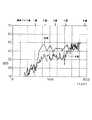
このように構成された送風機用のブラシレスモータ1において、ステータ31に方向の異なる電流が流れることで対向し合うコア61と永久磁石55との間で、S・NあるいはS・S又はN・Nとなり、吸引・吸発力が発生し、回転駆動力が得られる。この運転中において、垂直筒部71に発生した振動は、薄肉部75を支点とする独立した振動となるため、薄肉部75を境として、軸受部63への振動は伝わりにくくなり、大幅に低減される。特に、この実施形態にあっては、薄肉部75に設けられた周溝77との組合せによって、軸受部63への振動伝達はさらに小さく低減されるようになる。この結果、振動エネルギーが吸収されたかたちとなるため、シャフト5への振動伝達が抑えられ、回路保護ケース7の固有振動数との共振が回避される。これにより、図8に示す如く、従来に比べてうなり音の発生を小さく抑え、品質感を高めることができる。
【0036】
図9から図16はヨーク53からの振動を回路保護ケース7へ伝わるのを小さく抑えるようにした第2の実施形態を示したものである。
【0037】
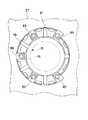
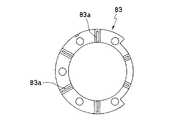
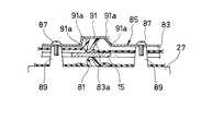
即ち、図10に示すように、回路保護ケース7のアッパーケース27側に設けられた組付け凹部79内に、防振ゴムとなる下位側弾性部材81をセットし、その上から鎖線で示すように、固定ハウジング11の取付けフランジ部15を重ね合せ、さらにその上から図11に示す防振ゴムとなる上位側弾性部材83を重ね合せ、前記取付けフランジ部15を挟みつける。さらに、その上から図13に示す所定幅に形成されたリング状の固定支持プレート85を重ね合せ、それらは取付けビス87により、前記組付け凹部79内に設けられた円筒状の取付部89に固定支持されている。
【0038】
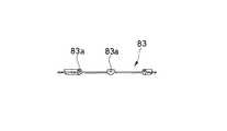
固定支持プレート85には、上方へ向かって屈曲成形された屈曲部91aを有する下向きコ字状の振動緩和屈曲部91が複数設けられている。振動緩和屈曲部91の天井部内側には、前記上位側弾性部材83に設けられた突起体83aが弾接し合う形状となっている。
【0039】
ヨーク53は、軸受部63と、水平部65と、傾斜部69と垂直筒部71とから成り、垂直筒部71の内側は永久磁石55が配置された構造となっている。
【0040】
なお、他の構成要素は、第1の実施形態と同一のため、同一符号を付して詳細な説明を省略する。
【0041】
したがって、この第2の実施形態によれば、ヨーク53の垂直筒部71で発生した振動は、固定支持プレート85において、図15に鎖線で示すように屈曲部91aが屈曲変形することで、回路保護ケース7に伝わる動きが大幅に低減される。また、水平方向の振動に対しても、図16に示すように屈曲部91aが変形することで回路保護ケース7への駆動伝達が低減される。この結果、振動緩和屈曲部91で振動エネルギーが吸収されたかたちとなるため、回路保護ケース7の固有振動数との共振が回避され、うなり音(磁気音)を小さく抑えることができる。これにより、品質感を高めることができる。
【0042】
なお、この実施形態の場合には、リング状の振動緩和領域75をヨーク53に設ける第1の実施形態と組合せることで、より一層のうなり音(磁気音)を小さくすることが可能となる。
【図面の簡単な説明】
【図1】この発明にかかる送風機用のブラシレスモータを示した概要切断面図。
【図2】送風用のファンの一部分を切断した送風機用のブラシレスモータを示した説明図。
【図3】ヨークの平面図。
【図4】ヨークの切断面図。
【図5】ヨークの肩部に薄肉部を設けた一部分の拡大断面図。
【図6】周溝の溝形状の別の実施形態を示した拡大説明図。
【図7】周溝の溝形状の別の実施形態を示した拡大説明図。
【図8】従来例と本案との測定モード結果を示した説明図。
【図9】第2の実施形態を示した図2と同様の説明図。
【図10】固定ハウジングの取付けフランジ部の下側にセットされる下位側弾性部材を回路保護ケースの取付け部にセットした平面図。
【図11】固定ハウジングの取付けフランジ部の上側にセットされる上位側弾性部材の平面図。
【図12】上位側弾性部材の側面図。
【図13】上位側弾性部材を介して固定ハウジングの取付けフランジを上から押える固定支持プレートの平面図。
【図14】固定支持プレートの側面図。
【図15】固定支持プレートの動作図。
【図16】固定支持プレートの動作図。
【符号の説明】
5 シャフト
7 回路保護ケース
11 固定ハウジング
31 ステータ
53 ヨーク
55 磁石
63 軸受部
71 垂直筒部
73 振動緩和領域[0001]
BACKGROUND OF THE INVENTION
The present invention relates to a brushless motor for a blower suitable for an air conditioner for automobiles.
[0002]
[Prior art]
Conventionally, the outline of a brushless motor for a blower used for an air conditioner for automobiles is that a shaft rises from a circuit protection case that also serves as an attachment member, and a fan for blowing is attached to the shaft.
[0003]
In the fan for blowing air, the rotational power from the drive unit is given through the shaft. The drive unit is opposed to the yoke mounted on the shaft, a plurality of magnets provided in order of S pole, N pole, S pole on the inner peripheral wall surface of the yoke, and rotatably supports the shaft. It has a structure comprising a stator provided in a fixed housing.
[0004]
[Problems to be solved by the invention]
As described above, the yoke has a cylindrical shape in which a magnet is provided on the inner peripheral wall surface and a lower part is opened so as to surround the stator facing the magnet.
[0005]
On the other hand, the drive unit is configured to generate a drive force while repeating attraction and repulsion between the opposing magnets, for example, by switching the current of the stator coil 12 times per rotation. At this time, since the yoke provided with the magnet becomes a cylindrical free end whose lower part is opened, it is easily deformed in response to attraction and repulsive force, which is transmitted to the shaft as vibration energy.
[0006]
Since the shaft rises from the circuit protection case, the vibration transmitted to the shaft resonates around the natural frequency of the circuit protection case and the case where the motor is mounted, for example, around 240 Hz. ) And become noticeable.
[0007]
There is an urgent need to keep this roaring sound as small as possible because it significantly impairs the quality.
[0008]
Accordingly, an object of the present invention is to provide a brushless motor for a blower that can suppress a beat noise with a simple device.
[0009]
[Means for Solving the Problems]
In order to achieve the above object, according to a first aspect of the present invention,a bearing portion mounted on a shaft rising from acircuit protection case, and a vertical cylinder portion which is continuously formed integrally with the bearing portion and opened downward. And a stator provided on a fixed housing that faces the magnet and rotatably supports the shaft, and a mounting flange portion of the fixed housing from above. In a brushless motor for a blower having a presser and a fixed support plate having a predetermined width formed in a ring shape that is fixed to the upper case of the circuit protection case, the fixed support plate is provided with a vibration relaxation bending portion that rises upward .
[0018]
As a result, when a current flows through the stator, driving force is generated while repeating attraction and repulsion between the opposing magnets. At this time, the vibration generated in the yoke is bent and deformed in the vibration-reducing bending portion in the fixed support plate, so that the movement transmitted to the circuit protection case is greatly reduced. As a result, the vibration energy is absorbed by the vibration relaxation bent portion, and resonance with the natural frequency of the circuit protection case is avoided.
[0019]
【The invention's effect】
As described above, according to the first aspect of the present invention,the vibration generated in the yoke that is the generation source of the beat sound during operationis transferred to the circuit protection case by the bending deformation by the vibration relaxation bending portion provided in the fixed support plate. The vibration transmission of can be kept small. As a result, resonance with the natural frequency of the circuit protection case is avoided, and the generation of beat noise is reduced .
[0023]
DETAILED DESCRIPTION OF THE INVENTION
Hereinafter, the first embodiment of the present invention will be described in detail with reference to the drawings of FIGS.
[0024]
In FIG. 1,
[0025]
The
[0026]
The
[0027]
In the
[0028]
The
[0029]
The
[0030]
The
[0031]
As shown in FIG. 5, a thin-
[0032]
The
[0033]
The
[0034]
On the other hand, the
[0035]
In the
[0036]
FIGS. 9 to 16 show a second embodiment in which the vibration from the
[0037]
That is, as shown in FIG. 10, a lower-side
[0038]
The fixed
[0039]
The
[0040]
Since other components are the same as those in the first embodiment, the same reference numerals are given and detailed descriptions thereof are omitted.
[0041]
Therefore, according to the second embodiment, the vibration generated in the vertical
[0042]
In the case of this embodiment, by combining with the first embodiment in which the ring-shaped
[Brief description of the drawings]
FIG. 1 is a schematic sectional view showing a brushless motor for a blower according to the present invention.
FIG. 2 is an explanatory view showing a brushless motor for a blower in which a part of a fan for blowing is cut.
FIG. 3 is a plan view of a yoke.
FIG. 4 is a sectional view of a yoke.
FIG. 5 is an enlarged cross-sectional view of a part in which a thin portion is provided on a shoulder portion of a yoke.
FIG. 6 is an enlarged explanatory view showing another embodiment of the groove shape of the circumferential groove.
FIG. 7 is an enlarged explanatory view showing another embodiment of the groove shape of the circumferential groove.
FIG. 8 is an explanatory diagram showing measurement mode results of a conventional example and the present plan.
FIG. 9 is an explanatory view similar to FIG. 2 showing the second embodiment.
FIG. 10 is a plan view in which a lower elastic member set on the lower side of the mounting flange portion of the fixed housing is set on the mounting portion of the circuit protection case.
FIG. 11 is a plan view of an upper elastic member set on the upper side of the mounting flange portion of the fixed housing.
FIG. 12 is a side view of the upper elastic member.
FIG. 13 is a plan view of a fixed support plate for pressing a mounting flange of a fixed housing from above via an upper elastic member.
FIG. 14 is a side view of a fixed support plate.
FIG. 15 is an operation diagram of the fixed support plate.
FIG. 16 is an operation diagram of the fixed support plate.
[Explanation of symbols]
5
Claims (1)
Translated fromJapanesePriority Applications (4)
| Application Number | Priority Date | Filing Date | Title |
|---|---|---|---|
| JP18055299AJP4077983B2 (en) | 1999-06-25 | 1999-06-25 | Brushless motor for blower |
| US09/502,019US6236126B1 (en) | 1999-06-25 | 2000-02-11 | Brushless motor |
| EP00103997AEP1063752B1 (en) | 1999-06-25 | 2000-02-25 | Brushless Motor |
| DE60010580TDE60010580T2 (en) | 1999-06-25 | 2000-02-25 | Brushless motor |
Applications Claiming Priority (1)
| Application Number | Priority Date | Filing Date | Title |
|---|---|---|---|
| JP18055299AJP4077983B2 (en) | 1999-06-25 | 1999-06-25 | Brushless motor for blower |
Publications (2)
| Publication Number | Publication Date |
|---|---|
| JP2001016836A JP2001016836A (en) | 2001-01-19 |
| JP4077983B2true JP4077983B2 (en) | 2008-04-23 |
Family
ID=16085282
Family Applications (1)
| Application Number | Title | Priority Date | Filing Date |
|---|---|---|---|
| JP18055299AExpired - Fee RelatedJP4077983B2 (en) | 1999-06-25 | 1999-06-25 | Brushless motor for blower |
Country Status (4)
| Country | Link |
|---|---|
| US (1) | US6236126B1 (en) |
| EP (1) | EP1063752B1 (en) |
| JP (1) | JP4077983B2 (en) |
| DE (1) | DE60010580T2 (en) |
Families Citing this family (29)
| Publication number | Priority date | Publication date | Assignee | Title |
|---|---|---|---|---|
| US6111329A (en)* | 1999-03-29 | 2000-08-29 | Graham; Gregory S. | Armature for an electromotive device |
| EP1130745A3 (en)* | 2000-03-02 | 2003-12-10 | Calsonic Kansei Corporation | Brushless motor |
| US6619527B1 (en)* | 2000-10-10 | 2003-09-16 | Illinois Tool Works Inc. | Combustion powered tool suspension for iron core fan motor |
| DE10063619B4 (en)* | 2000-12-20 | 2010-02-18 | Trw Automotive Electronics & Components Gmbh & Co. Kg | Drive unit for blowers in vehicles |
| US6593674B2 (en)* | 2001-02-26 | 2003-07-15 | Woodward Governor Company | Vibration isolator and actuator incorporating same for isolating integral electronics |
| US20020158544A1 (en)* | 2001-04-26 | 2002-10-31 | Bobay Dennis P. | External rotor cup with annular flange extending therefrom |
| US6873085B2 (en) | 2001-05-16 | 2005-03-29 | G & G Technology, Inc. | Brushless motor |
| DE10161367A1 (en) | 2001-12-14 | 2003-07-03 | Conti Temic Microelectronic | Electric drive unit |
| US6674198B2 (en)* | 2002-01-04 | 2004-01-06 | Siemens Vdo Automotive Inc. | Electric motor with integrated heat shield |
| JP3593102B2 (en)* | 2002-01-08 | 2004-11-24 | 三菱電機株式会社 | Electric power steering device |
| US20040071003A1 (en)* | 2002-09-04 | 2004-04-15 | G & G Technology, Inc. | Split phase polyphase inverter |
| KR20050099352A (en)* | 2004-04-09 | 2005-10-13 | 엘지전자 주식회사 | Front suction/discharge type outdoor unit for air conditioner |
| US7180212B2 (en)* | 2004-07-02 | 2007-02-20 | Visteon Global Technologies, Inc. | Electric machine with integrated electronics in a circular/closed-loop arrangement |
| KR101189447B1 (en) | 2006-08-30 | 2012-10-09 | 엘지전자 주식회사 | Outer rotor type fan-motor |
| ITTO20080159A1 (en)* | 2008-03-04 | 2009-09-05 | Johnson Electric Moncalieri Srl | MOTORIZED ELECTRIC APPLIANCE, IN A PARTICULAR ELECTRIC MOTOR-DRIVER. |
| US20100247229A1 (en)* | 2009-03-31 | 2010-09-30 | Gm Global Technology Operations, Inc. | End ring for a vehicular electric machine |
| US20110116928A1 (en)* | 2009-11-16 | 2011-05-19 | Robert Bosch Gmbh | Open-hub centrifugal blower assembly |
| JP2012013035A (en)* | 2010-07-02 | 2012-01-19 | Daikin Industries Ltd | Air blowing device |
| DE102010031303A1 (en)* | 2010-07-14 | 2012-01-19 | Robert Bosch Gmbh | fan module |
| JP2012095404A (en)* | 2010-10-25 | 2012-05-17 | Mitsuba Corp | Vehicle electric fan |
| DE102011090066A1 (en)* | 2011-12-29 | 2013-07-04 | Robert Bosch Gmbh | fan module |
| FR3004027A1 (en)* | 2013-03-26 | 2014-10-03 | Valeo Systemes Thermiques | DECOUPLING PIECE BETWEEN AN ENGINE AND ITS SUPPORT, AND ASSEMBLY OF AN ENGINE ON ITS SUPPORT INTEGRATING SUCH A DECOUPLING PART |
| TWI551013B (en)* | 2015-01-19 | 2016-09-21 | 建準電機工業股份有限公司 | Motor of ceiling fan |
| FR3043150B1 (en)* | 2015-10-29 | 2019-10-11 | Valeo Systemes Thermiques | FAN MOTOR ASSEMBLY AND HEATING, VENTILATION AND / OR AIR CONDITIONING SYSTEM FOR A CORRESPONDING MOTOR VEHICLE |
| JP6726630B2 (en)* | 2017-02-08 | 2020-07-22 | 株式会社ケーヒン | Blower motor unit for air conditioning |
| FR3062971B1 (en)* | 2017-02-13 | 2021-10-01 | Valeo Systemes Thermiques | MOUNTING KIT OF AN ENGINE IN AN AIR PULSION DEVICE FOR A HEATING, VENTILATION AND / OR AIR CONDITIONING DEVICE OF A MOTOR VEHICLE |
| JP6568914B2 (en)* | 2017-09-13 | 2019-08-28 | シナノケンシ株式会社 | Blower |
| JP6635994B2 (en)* | 2017-09-13 | 2020-01-29 | シナノケンシ株式会社 | Blower |
| CN108105165A (en)* | 2018-02-05 | 2018-06-01 | 德州科瑞特风机有限公司 | Magnetic suspension damping wind turbine |
Family Cites Families (9)
| Publication number | Priority date | Publication date | Assignee | Title |
|---|---|---|---|---|
| NL8400780A (en)* | 1984-03-12 | 1985-10-01 | Philips Nv | ROTOR FOR AN ELECTRICAL MACHINE. |
| US4883982A (en)* | 1988-06-02 | 1989-11-28 | General Electric Company | Electronically commutated motor, blower integral therewith, and stationary and rotatable assemblies therefor |
| JPH04109838A (en) | 1990-08-28 | 1992-04-10 | Mitsubishi Electric Corp | brushless motor |
| JP2910222B2 (en) | 1990-10-31 | 1999-06-23 | ダイキン工業株式会社 | Electric motor |
| US5402024A (en)* | 1992-04-06 | 1995-03-28 | Matsushita Electric Industrial Co., Ltd. | Rotor for a permanent-magnet motor |
| JPH06205561A (en) | 1992-12-28 | 1994-07-22 | Daikin Ind Ltd | Dc brushless motor |
| JPH089616A (en) | 1994-06-23 | 1996-01-12 | Zexel Corp | Brushless motor |
| US5798589A (en)* | 1995-09-13 | 1998-08-25 | Zexel Corporation | Brushless motor having lubrication system for upper and lower bearings |
| JPH10191595A (en) | 1996-12-20 | 1998-07-21 | Calsonic Corp | Vehicle mounted fan |
- 1999
- 1999-06-25JPJP18055299Apatent/JP4077983B2/ennot_activeExpired - Fee Related
- 2000
- 2000-02-11USUS09/502,019patent/US6236126B1/ennot_activeExpired - Fee Related
- 2000-02-25DEDE60010580Tpatent/DE60010580T2/ennot_activeExpired - Fee Related
- 2000-02-25EPEP00103997Apatent/EP1063752B1/ennot_activeExpired - Lifetime
Also Published As
| Publication number | Publication date |
|---|---|
| EP1063752A1 (en) | 2000-12-27 |
| EP1063752B1 (en) | 2004-05-12 |
| JP2001016836A (en) | 2001-01-19 |
| DE60010580T2 (en) | 2004-09-16 |
| US6236126B1 (en) | 2001-05-22 |
| DE60010580D1 (en) | 2004-06-17 |
Similar Documents
| Publication | Publication Date | Title |
|---|---|---|
| JP4077983B2 (en) | Brushless motor for blower | |
| JP6726630B2 (en) | Blower motor unit for air conditioning | |
| JP6726631B2 (en) | Blower motor unit for air conditioning | |
| JP4716065B2 (en) | Axial blower | |
| JP4475953B2 (en) | Electric blower | |
| CN107134893B (en) | Idle call blower motor component | |
| CN109274222B (en) | Blower motor unit for air conditioner | |
| JP4402712B2 (en) | Controller-integrated rotating electrical machine | |
| JP2019030182A (en) | Brushless motor for air conditioning apparatus | |
| JP2020051358A (en) | Control panel and water supply | |
| JP2002320366A (en) | Brushless motor | |
| JP2003100432A (en) | Induction heating cooker | |
| JP2018207730A (en) | Blower motor unit for air conditioner | |
| JP3509288B2 (en) | Brushless DC motor | |
| JP2000213361A (en) | Cooling structure for engine generator | |
| CN220234407U (en) | Heat abstractor of brushless motor | |
| JP4254164B2 (en) | Brushless motor | |
| CN222717141U (en) | Volute assembly and household appliance | |
| JP5402892B2 (en) | Heat dissipation structure of load drive control device | |
| JPH10252697A (en) | Motor integrated fan device and air blower using its device | |
| CN219345029U (en) | Fan wind channel and washing machine | |
| JP2002186234A (en) | Brushless motor | |
| JPH08312585A (en) | Control circuit board of motor built-in type blower | |
| JP2021061656A (en) | motor | |
| JP2005130659A (en) | Brushless motor and motor fan |
Legal Events
| Date | Code | Title | Description |
|---|---|---|---|
| A621 | Written request for application examination | Free format text:JAPANESE INTERMEDIATE CODE: A621 Effective date:20050127 | |
| A977 | Report on retrieval | Free format text:JAPANESE INTERMEDIATE CODE: A971007 Effective date:20070704 | |
| A131 | Notification of reasons for refusal | Free format text:JAPANESE INTERMEDIATE CODE: A131 Effective date:20070807 | |
| A521 | Request for written amendment filed | Free format text:JAPANESE INTERMEDIATE CODE: A523 Effective date:20071001 | |
| TRDD | Decision of grant or rejection written | ||
| A01 | Written decision to grant a patent or to grant a registration (utility model) | Free format text:JAPANESE INTERMEDIATE CODE: A01 Effective date:20080129 | |
| A61 | First payment of annual fees (during grant procedure) | Free format text:JAPANESE INTERMEDIATE CODE: A61 Effective date:20080204 | |
| R150 | Certificate of patent or registration of utility model | Free format text:JAPANESE INTERMEDIATE CODE: R150 | |
| FPAY | Renewal fee payment (event date is renewal date of database) | Free format text:PAYMENT UNTIL: 20110208 Year of fee payment:3 | |
| S531 | Written request for registration of change of domicile | Free format text:JAPANESE INTERMEDIATE CODE: R313531 | |
| FPAY | Renewal fee payment (event date is renewal date of database) | Free format text:PAYMENT UNTIL: 20110208 Year of fee payment:3 | |
| R350 | Written notification of registration of transfer | Free format text:JAPANESE INTERMEDIATE CODE: R350 | |
| LAPS | Cancellation because of no payment of annual fees |