JP4077330B2 - Data generator - Google Patents
Data generatorDownload PDFInfo
- Publication number
- JP4077330B2 JP4077330B2JP2003029355AJP2003029355AJP4077330B2JP 4077330 B2JP4077330 B2JP 4077330B2JP 2003029355 AJP2003029355 AJP 2003029355AJP 2003029355 AJP2003029355 AJP 2003029355AJP 4077330 B2JP4077330 B2JP 4077330B2
- Authority
- JP
- Japan
- Prior art keywords
- multicast
- data
- client
- information
- transfer
- Prior art date
- Legal status (The legal status is an assumption and is not a legal conclusion. Google has not performed a legal analysis and makes no representation as to the accuracy of the status listed.)
- Expired - Fee Related
Links
Images


Classifications
- H—ELECTRICITY
- H04—ELECTRIC COMMUNICATION TECHNIQUE
- H04L—TRANSMISSION OF DIGITAL INFORMATION, e.g. TELEGRAPHIC COMMUNICATION
- H04L12/00—Data switching networks
- H04L12/02—Details
- H04L12/16—Arrangements for providing special services to substations
- H04L12/18—Arrangements for providing special services to substations for broadcast or conference, e.g. multicast
- H04L12/1886—Arrangements for providing special services to substations for broadcast or conference, e.g. multicast with traffic restrictions for efficiency improvement, e.g. involving subnets or subdomains
- H—ELECTRICITY
- H04—ELECTRIC COMMUNICATION TECHNIQUE
- H04L—TRANSMISSION OF DIGITAL INFORMATION, e.g. TELEGRAPHIC COMMUNICATION
- H04L65/00—Network arrangements, protocols or services for supporting real-time applications in data packet communication
- H04L65/1066—Session management
- H04L65/1101—Session protocols
- H—ELECTRICITY
- H04—ELECTRIC COMMUNICATION TECHNIQUE
- H04L—TRANSMISSION OF DIGITAL INFORMATION, e.g. TELEGRAPHIC COMMUNICATION
- H04L65/00—Network arrangements, protocols or services for supporting real-time applications in data packet communication
- H04L65/60—Network streaming of media packets
- H04L65/61—Network streaming of media packets for supporting one-way streaming services, e.g. Internet radio
- H04L65/611—Network streaming of media packets for supporting one-way streaming services, e.g. Internet radio for multicast or broadcast
- H—ELECTRICITY
- H04—ELECTRIC COMMUNICATION TECHNIQUE
- H04N—PICTORIAL COMMUNICATION, e.g. TELEVISION
- H04N21/00—Selective content distribution, e.g. interactive television or video on demand [VOD]
- H04N21/60—Network structure or processes for video distribution between server and client or between remote clients; Control signalling between clients, server and network components; Transmission of management data between server and client, e.g. sending from server to client commands for recording incoming content stream; Communication details between server and client
- H04N21/63—Control signaling related to video distribution between client, server and network components; Network processes for video distribution between server and clients or between remote clients, e.g. transmitting basic layer and enhancement layers over different transmission paths, setting up a peer-to-peer communication via Internet between remote STB's; Communication protocols; Addressing
- H04N21/64—Addressing
- H04N21/6405—Multicasting
- H—ELECTRICITY
- H04—ELECTRIC COMMUNICATION TECHNIQUE
- H04L—TRANSMISSION OF DIGITAL INFORMATION, e.g. TELEGRAPHIC COMMUNICATION
- H04L12/00—Data switching networks
- H04L12/02—Details
- H04L12/16—Arrangements for providing special services to substations
- H04L12/18—Arrangements for providing special services to substations for broadcast or conference, e.g. multicast
- H04L12/185—Arrangements for providing special services to substations for broadcast or conference, e.g. multicast with management of multicast group membership
Landscapes
- Engineering & Computer Science (AREA)
- Multimedia (AREA)
- Signal Processing (AREA)
- Computer Networks & Wireless Communication (AREA)
- Business, Economics & Management (AREA)
- General Business, Economics & Management (AREA)
- Data Exchanges In Wide-Area Networks (AREA)
- Small-Scale Networks (AREA)
Description
Translated fromJapanese【0001】
【発明の属する技術分野】
本発明は、マルチキャスト環境において、効率的にマルチキャストのデータを配信するための装置に関する。
【0002】
【従来の技術】
従来、音声や動画などのマルチメディアデータによるストリーミングデータ等の伝送の効率化を図る技術として、マルチキャストが利用されている。マルチキャストでは、基本的にオンデマンドのデータ配信を提供することはできない。しかし、マルチキャストは、リアルタイムの動画配信や音声配信(例:ライブ中継)において多くのメリットを有する。
【0003】
マルチキャストでは、クライアント数(データ受信を望むユーザ数)に関わらず、ある経路のトラフィック量を常に一定に保つことができる。このため、その他の通信に与える影響も少ない。従って、マルチキャストでは、ユニキャストと異なり、配信専用のネットワークやキャッシュサーバ等の設備を設ける必要がない。よって、マルチキャストでは、非常に安価なネットワーク構成によるマルチメディアデータの配信が可能となる。
【0004】
マルチキャストを実現する技術として、IGMP(Internet Group Management Protocol)やマルチキャストルーティングプロトコルがある。IGMPは、マルチキャストに対応するルータやレイヤ3スイッチ(以下、マルチキャストルータと呼ぶ)が、その配下に接続されるクライアント(エンドシステム)のマルチキャスト受信状態を把握するためのプロトコルである。マルチキャストルーティングプロトコルは、サーバから各クライアントまでのデータの配信経路を構成するために、マルチキャストルータ間で機能するプロトコルである。
【0005】
従来のIGMPバージョン1(IGMPv1)やIGMPバージョン2(IGMPv2)では、マルチキャストデータの宛て先アドレスとなるマルチキャストアドレスのみによって、マルチキャストグループの管理が行われる。なお、IGMPv2メッセージ対応のIPマルチキャスト通信において送信ホストを制限することが可能となるシステムを提供することを課題とする技術がある(特許文献1参照)。
【0006】
しかし、IGMPバージョン3(IGMPv3:非特許文献2参照)では、データの送信元であるサーバ(ソース)のアドレス(ソースアドレス)及びマルチキャストアドレスによってマルチキャストセッションが識別及び管理される。即ち、マルチキャストアドレスが同じであっても、ソースアドレスが異なるマルチキャストセッションは、異なるマルチキャストセッションとして認識される。従って、IGMPv3では、マルチキャストアドレスの重複使用が可能となる。このマルチキャストの形態は、SSM(Source Specific Multicast)と呼ばれ、今後のリアルタイム放送などへの適用が見込まれている。
【0007】
また、通常、LAN(Local Area Network)環境やインターネットアクセスのためのブロードバンド環境では、ルータあるいはレイヤ3スイッチとクライアントの間にはレイヤ2スイッチ(LANスイッチ)が設置される。そして、このレイヤ2スイッチが、エンドシステムを収容し、ルータあるいはレイヤ3スイッチに接続される。
【0008】
マルチキャストが利用されるネットワークで使用されるレイヤ2スイッチには、一般的には、IGMP Snooping機能が実装される。IGMP Snoopingでは、マルチキャストデータの受信を望むクライアント(レシーバ)が接続されているポートのみへマルチキャストデータが転送される。IGMPSnoopingでは、レイヤ2スイッチは、クライアントやマルチキャストルータによって送信されるIGMPメッセージを盗み見る(参照する)。そして、レイヤ2スイッチは、どのポートにマルチキャストルータが接続され、どのポートに接続されるクライアントがどのマルチキャストアドレス宛てのマルチキャストデータの受信を望んでいるかを把握し、マルチキャストデータの転送を行う。
【0009】
このように、IGMP Snoopingにより、必要とされるポートへのみマルチキャストデータを転送することが可能となる。このため、受信を望まないクライアントを含む全てのクライアントに対してマルチキャストデータが届くということが回避される。この時、IGMP Snoopingをサポートするレイヤ2スイッチは、レイヤ2の情報、即ちMACアドレスがマルチキャストであるか否かを判別する。そして、MACアドレスがマルチキャストである場合、レイヤ2スイッチは、必要とされるポートへのみマルチキャストデータを転送する。
【0010】
このように、レイヤ2スイッチは、IGMP Snoopingによって擬似的にIGMPの機能を実現する。即ち、IGMPやIP(Internet Protocol)マルチキャストはレイヤ3の機能であるが、レイヤ2スイッチはレイヤ2の情報を基に転送処理を制御する。従って、レイヤ2スイッチは、IGMP Snoopingをサポートしたとしても、レイヤ3に関する処理を行う必要がないため、そのパフォーマンスに大きな悪影響を被ることはなかった。
【0011】
【特許文献1】
特開2002−64558号公報
【非特許文献1】
”Multicast Listener Discovery Version 2 (MLDv2) for IPv6”、[online]、インターネット<URL:http://www.ietf.org/internet-drafts/draft-vida-mld-v2-06.txt>
【非特許文献2】
”Internet Group Management Protocol, Version 3”、[online]、インターネット<URL: http://www.ietf.org/rfc/rfc3376.txt?number=337>
【0012】
【発明が解決しようとする課題】
しかしながら、今後の普及が予想されるIGMPv3やMLDv2(Multicast Listener Discovery Version 2:非特許文献1参照)では、従来のIGMP(v1,v2)やMLD(v1)と異なり、レイヤ2レベルでの処理が不可能となる。ここで、MLDとは、IPv6における技術であり、IPv4におけるIGMPと同様の技術である。IGMPv3やMLDv2では、IPパケットのIPヘッダの次に来るペイロード部分にソースの情報や複数のマルチキャストアドレス等が格納される。これらの情報は、IGMPv3やMLDv2の機能の実現において不可欠である。このため、従来のIGMP Snoopingでは、IGMPv3やMLDv2の機能をレイヤ2スイッチで擬似的に実現することは不可能である。即ち、IGMP Snoopingを使用してIGMPv3やMLDv2の機能を実現するためには、レイヤ2スイッチは、IGMPパケットあるいはMLDv2パケットのレイヤ3の情報を参照する必要がある。IGMP Snoopingを使用してIGMPv3やMLDv2の機能を実現するためには、レイヤ2スイッチは、さらに、実際の転送処理においても、レイヤ3の情報を参照した後に、転送先となるポートを決定する必要がある。
【0013】
レイヤ2(MAC)の情報に基づいてフレームをスイッチするレイヤ2スイッチに対して、レイヤ3の情報を参照するという処理を実装することは、レイヤ2スイッチのパフォーマンスを著しく低下させ、機器自体を非常に複雑かつ高価にする原因となる。また、IGMP Snoopingを実現できないレイヤ2スイッチによってネットワークを構成することは、シェアドメディア(ハブ(HUB)等)によってクライアントが接続されている状態と同じこととなる。即ち、マルチキャストデータの受信を不要とするクライアントに対してもマルチキャストデータが転送され、他のユニキャスト通信やマルチキャスト通信に対して悪影響を与える。このため、レイヤ2スイッチによってクライアントを収容することによるメリットを失うこととなる。
【0014】
本発明は、このような問題を解決し、あるレイヤの情報(例えばレイヤ3の情報)を用いたマルチキャストグループ管理プロトコル(例えば、IGMPv3あるいはMLDv2)が使用されるネットワークにおいて、マルチキャストデータが、あるレイヤよりも低次のレイヤに基づいたスイッチを介して、このマルチキャストデータの受信を望むクライアントが接続されるポートのみに配信されるシステムや装置を提供することを目的とする。
【0015】
【課題を解決するための手段】
上記問題を解決するため、本発明は以下のような構成をとる。本発明の第一の態様は、第一のレイヤのデータに基づいてハードウェア的にスイッチングを行うスイッチング装置よりも上流に設置されるデータ生成装置であって、前記第一のレイヤよりも高次である第二のレイヤのデータから、転送データの転送処理に関する転送管理情報を読み出す読出手段と、前記読出手段によって読み出される前記転送管理情報を記憶する記憶手段と、前記記憶手段が記憶する前記転送管理情報に基づいて転送データの転送先となるクライアントを判断し、転送先となるクライアント数と同数の、それぞれのクライアントに対して送信される、受信された転送データと同等の内容を含む送信データを生成するデータ生成手段とを備える。
【0016】
本発明の第一の態様では、読出手段は、自装置の下流に設置されるスイッチング装置がスイッチングを行う際に参照するデータのレイヤよりも高次のレイヤのデータから、転送データの転送処理に関する転送管理情報を読み出す。例えば、自装置の下流に設置されるスイッチング装置がレイヤ2スイッチである場合、読出手段は、レイヤ3以上のレイヤのデータから転送管理情報を読み出す。このようなデータの例として、IGMPバージョン3のメッセージや、MLDバージョン2のメッセージ等がある。
【0017】
記憶手段は、読出手段によって読み出された転送管理情報に基づいた情報を記憶する。記憶手段は、読出手段によって読み出された転送管理情報をそのまま記憶しても良いし、他の手段(例えば管理手段)によって転送管理情報に基づいて作成された情報を記憶しても良い。
【0018】
データ生成手段は、転送管理情報に基づいて、転送データの転送先となる装置(クライアント)を判断する。データ生成手段は、転送先となるクライアント1台に対して一つのデータが送信されるように、転送データをコピーし変更する。データ生成手段は、転送先となるクライアントと同数のデータを生成するために、転送データのコピーを行う。そして、データ生成手段は、コピーされたデータの送信先のアドレスを、転送先となるクライアントのアドレスに変更する。
【0019】
このため、本発明の第一の態様によれば、転送データは、転送管理情報に基づいて、転送先となる各クライアントに対して1対1に送信される。このため、自装置の下流に設置されるスイッチング装置は、転送データについて転送管理情報に基づいた処理を実施する必要がない。即ち、自装置の下流に設置されるスイッチング装置が、より高次のレイヤの情報(転送管理情報)を読み出す必要がない。従って、このスイッチング装置がより高次のレイヤの情報を読み出す事による処理の遅延や、このようにスイッチング装置を設計することによるコストを削減することが可能となる。
【0020】
本発明の第二の態様は、データ生成装置であって、レイヤ2よりも高次のレイヤのデータから、マルチキャストデータの転送処理に関する情報を読み出す読出手段と、前記読出手段によって読み出された情報に基づいた転送管理情報を記憶する記憶手段と、受信されたマルチキャストデータを、前記記憶手段が記憶する前記転送管理情報に基づいて、転送先となるクライアント数と同数のデータにコピーし、コピーされた夫々のデータをユニキャストデータに変更するデータ生成手段とを備える。
【0021】
また、本発明の第二の態様の前記データ生成手段は、前記コピーされた夫々のデータのMACアドレスを、転送先となる各クライアントのMACアドレスに書き換えることによりユニキャストデータを生成するように構成されても良い。
【0022】
また、本発明の第二の態様は、自装置よりも下流側にデータを送出する送出手段をさらに備え、前記送出手段は、前記データ生成手段によって生成されるユニキャストデータ及び受信されたマルチキャストデータを送出するように構成されても良い。
【0023】
また、本発明の第二の態様は、前記読出手段によって読み出された情報に基づいて、前記記憶手段に記憶される前記転送管理情報を更新する管理手段をさらに備えるように構成されても良い。
【0024】
また、本発明の第二の態様は、前記読出手段によって読み出された情報がマルチキャストグループへの加入を示す情報である場合、前記管理手段はこの情報の内容を前記記憶手段に記憶される前記転送管理情報に反映させるように構成されても良い。
【0025】
また、本発明の第二の態様は、前記読出手段によって読み出された情報がマルチキャストグループからの離脱を示す情報である場合、前記管理手段はこの情報の送信元であるクライアントに関する情報を前記転送管理情報から削除するように構成されても良い。
【0026】
また、本発明の第二の態様は、一定時間を計時する計時手段をさらに備え、前記計時手段が、応答要求に対する応答がクライアントから一定時間以上受信されていないと判断した場合、前記管理手段はこのクライアントに関する情報を前記転送管理情報から削除するように構成されても良い。
【0027】
また、本発明の第二の態様の前記記憶手段は、前記転送管理情報として、マルチキャストデータが転送されるべきクライアントのアドレスと、このマルチキャストデータの送信先アドレスとを関連付けて記憶し、前記転送管理情報に基づいて、マルチキャストデータが転送されるべきクライアントを示すクライアント識別子と、このマルチキャストデータの送信先を示す送信先識別子と、このクライアント及びこのマルチキャストデータの送信先が関連付けて前記転送管理情報に記憶された時間と、このクライアント及びこのマルチキャストデータの送信先に関する情報が前記転送管理情報から削除された時間と、を関連付けて記憶するクライアント管理情報記憶手段をさらに備えるように構成されても良い。
【0028】
また、本発明の第二の態様の前記記憶手段は、前記転送管理情報として、マルチキャストデータが転送されるべきクライアントのアドレスと、このマルチキャストデータの送信先アドレスと、マルチキャストデータの送信元アドレスとを関連付けて記憶し、前記転送管理情報に基づいて、マルチキャストデータが転送されるべきクライアントを示すクライアント識別子と、このマルチキャストデータの送信先を示す送信先識別子と、このマルチキャストデータの送信元を示す送信元識別子と、このクライアント及びこのマルチキャストデータの送信先が関連付けて前記転送管理情報に記憶された時間と、このクライアント及びこのマルチキャストデータの送信先に関する情報が前記転送管理情報から削除された時間と、を関連付けて記憶するクライアント管理情報記憶手段をさらに備えるように構成されても良い。
【0029】
また、前記読出手段によって読み出された情報がマルチキャスト受信状態の変更を示す情報である場合、前記管理手段はこの情報の内容を用いて前記記憶手段に記憶される前記転送管理情報を更新するように構成されても良い。
【0030】
【発明の実施の形態】
〔IPマルチキャスト〕
〈概要〉
本発明が前提としているIPマルチキャストの仕組みについて説明する。なお、以下の説明では、データリンク層がイーサネットである場合について説明する。
【0031】
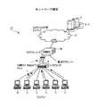
図1は、IPマルチキャストを用いたネットワークの構成例を示す図である。IPマルチキャストでは、アドレスとしてマルチキャストアドレスが使用される。IPマルチキャストは、エンドシステムであるサーバ(ソース)E1とクライアント(レシーバ)E2とマルチキャストルータM1間で機能する。
【0032】
IPマルチキャストでは、マルチキャストアドレスに対してマルチキャストデータが送信される。マルチキャストデータは、マルチキャスト対応ネットワークN1,マルチキャストルータM1,レイヤ2スイッチL1を介して、マルチキャストグループに属するクライアントE2によって受信される。IPv4環境におけるIPマルチキャストは、マルチキャストグループ管理プロトコルであるIGMPと、マルチキャストルーティングプロトコルによって実現される。
【0033】
IGMPのメッセージ(マルチキャストグループ制御メッセージ,IGMPメッセージ)は、クライアントE2と近隣のマルチキャストルータM1との間で(レイヤ2スイッチL1を挟んで)交換される。IGMPにより、マルチキャストルータM1は、自身の配下に位置する各クライアントE2のマルチキャストグループを把握する。
【0034】
マルチキャストルーティングプロトコルのメッセージは、マルチキャストルータM1間で(レイヤ2スイッチL1を挟んで)交換される。マルチキャストルーティングプロトコルにより、マルチキャストルータM1間で、サーバE1から複数の各クライアントE2(受信クライアント)までのマルチキャストデータ配信ツリーが構築される。
【0035】
次に、IPマルチキャストによるデータ伝送の基本動作について説明する。まず、マルチキャストデータの受信を望むクライアントE2は、IGMPメッセージによって、ローカルネットワークのマルチキャストルータM1へその旨を通知する。この通知により、このクライアントE2は、マルチキャストグループに参加したこととなる。即ち、このクライアントE2は、マルチキャストグループのメンバとなる。
【0036】
サーバE1は、クラスDのアドレスで識別されるマルチキャストアドレス宛てに、マルチキャストデータ(例えばストリームデータ)を送信する。このとき、サーバE1は、マルチキャストグループに属するクライアントの数に関わらず、一つのマルチキャストデータを送信する。
【0037】
マルチキャスト対応ネットワークN1内のマルチキャストルータM1は、サーバE1から送信されたマルチキャストデータを受信する。マルチキャストルータM1は、このマルチキャストデータのマルチキャストグループに参加している各クライアントE2への経路に沿って、このマルチキャストデータを必要に応じてコピーしながら伝送してゆく。即ち、マルチキャストルータM1は、マルチキャストルーティングプロトコルによって構成された、送信ホスト(サーバE1)から各クライアントE2へ至るマルチキャストデータ配信の経路木に沿って、マルチキャストデータを配信する。従って、最終的に、サーバE1が送信した一つのマルチキャストデータは、ネットワーク内の複数のクライアントE2へ配信される。
【0038】
次に、マルチキャストアドレス,IGMP,マルチキャストルーティングプロトコルそれぞれについて説明する。
【0039】
〈マルチキャストアドレス〉
IPv4におけるマルチキャストアドレスについて説明する。マルチキャストアドレスは、クラスDアドレスとして規定されており、10進表記で、”224.0.0.0”から”239.255.255.255”の範囲の値をとる。このため、クラスDアドレスは、最初の4ビットの”1110”によって識別される。
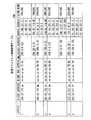
【0040】
図2は、マルチキャストアドレスの割り当てを示す表である。図2に示されるように、いくつかのマルチキャストアドレスは、特定用途のために予約されている。そして、ローカルサイト用の割り当て、即ち”239.0.0.0”から”239.255.255.255”までのアドレスが、例えば企業ネットワークやISP(Internet Service Provider)等で一般に使用されるマルチキャストアドレスである。
【0041】
また、最近ではSSMという概念やプロトコルもIETFにて検討されている。SSMとは、マルチキャストアドレス(マルチキャストグループアドレス)とマルチキャストデータのソースアドレスとの組によって識別されるマルチキャストセッション、あるいはその仕組みのことである。SSMのためのマルチキャストアドレスの範囲は、IPv4クラスDアドレスのうち、”232.0.0.0”から”232.255.255.255”である。
【0042】
尚、SSMでは、受信されるマルチキャストデータのソースアドレスがIGMPによって指定されるため、マルチキャストルータやエンドシステムにおいてIGMPv3が実装されていなければならない。
【0043】
〈IGMP〉
次に、IGMPについて説明する。クライアント(ホスト)とマルチキャストルータとは、IGMPメッセージをやり取りする。このIGMPメッセージによって、マルチキャストルータは、自身が接続されるローカルネットワークにおけるクライアントを把握/管理する。言い換えれば、IGMPは、クライアントが、あるマルチキャストグループに参加することをマルチキャストルータに伝えるためのプロトコルである。この場合、マルチキャストルータとクライアントとは、IGMPで規定されている各機能が実装される必要がある。IGMPには、バージョン1(v1)からバージョン3(v3)まである。IGMPv1は、RFC1112の付録1で規定されている。IGMPv2は、RFC2236で規定されている。IGMPv3は、RFC3376で規定されている。
【0044】
IGMPv1とIGMPv2とIGMPv3とは、それぞれマルチキャストグループ管理を行う点では同じだが、それぞれ異なる機能を有するプロトコルである。以下に、各バージョンのIGMPについて説明する。
【0045】
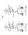
〈〈IGMPv1〉〉
図3は、IGMPv1の概要を示す図である。図3を用いて、IGMPv1について、クライアントE2がマルチキャストグループに参加する場合の処理(図3(a)参照)と、クライアントE2がマルチキャストグループから離脱する場合の処理(図3(b)参照)とを説明する。
【0046】
まず、図3(a)を用いて、クライアントE2がマルチキャストグループに参加する場合の処理について説明する。IGMPv1では、マルチキャストルータ(IGMP Querierルータ)M1は、サブネットに対してクエリメッセージ(General Query)を定期的に送信する(1)。マルチキャストグループに参加を希望するクライアントE2は、このクエリメッセージへの応答として、このマルチキャストグループの情報をレポートメッセージ(Report)に格納し送信する。言い換えれば、クライアントE2は、クエリメッセージに応答して、参加を希望するグループを指定したレポートメッセージを送信する(2)。マルチキャストルータM1は、このレポートメッセージを受信した場合、このレポートメッセージを受信したインタフェースに対して、このマルチキャストグループに対応するマルチキャストアドレスへ送信されたデータ(マルチキャストデータ)を、このクライアントE2に対して転送するように設定する。
【0047】
次に、図3(b)を用いて、クライアントE2がマルチキャストグループから離脱する場合の処理について説明する。あるマルチキャストグループに参加しているクライアントE2は、アプリケーション等の終了によってマルチキャストに関する自身の機能を停止し、マルチキャストデータの受信を中止する(3)。この処理によって、このクライアントE2は、マルチキャストグループから離脱する。この場合、クライアントE2は、クエリメッセージに対して応答しない。
【0048】
マルチキャストルータM1は、クライアントE2から一定時間レポートメッセージを受信しない場合、タイムアウトによってこのクライアントE2がマルチキャストグループから離脱したことを認識する(4)。そして、この認識の後、マルチキャストルータM1は、マルチキャストデータをこのクライアントE2に転送する処理を中止する。
【0049】
このように、マルチキャストルータM1は、クエリメッセージに対応するレポートメッセージの受信についてのタイムアウトによって、クライアントE2がマルチキャストグループに参加しているか否かを把握する。このため、クライアントE2がマルチキャストグループから離脱しても、タイムアウトが発生するまで、マルチキャストルータM1は、クライアントE2へマルチキャストデータの転送を実行する。即ち、タイムアウトが発生するまで、このクライアントE2が接続されるサブネットにマルチキャストデータが流れ続ける。
【0050】
〈〈IGMPv2〉〉
図4は、IGMPv2の概要を示す図である。図4を用いて、IGMPv2について、クライアントE2がマルチキャストグループに参加する場合の処理(図4(a)参照)と、クライアントE2がマルチキャストグループから離脱する場合の処理(図4(b)参照)とを説明する。
【0051】
まず、図4(a)を用いて、クライアントE2がマルチキャストグループに参加する場合の処理について説明する。IGMPv2では、IGMPv1と同様に、マルチキャストルータM1は、サブネットに対してクエリメッセージを定期的に送信する(1)。マルチキャストグループに参加を希望するクライアントE2は、クエリメッセージへの応答として、このマルチキャストグループの情報をレポートメッセージに格納して送信する(2)。マルチキャストルータM1は、このレポートメッセージを受信した場合、このレポートメッセージを受信したインタフェースに対して、このマルチキャストグループに対応するマルチキャストデータを、このクライアントE2に対して転送するように設定する。
【0052】
IGMPv2では、クライアントE2は、マルチキャストグループに参加を希望する時点で、クエリメッセージの受信に関係なく、Unsolicited Reportを送信することが可能である。マルチキャストルータM1は、Unsolicited Reportを受信した場合、配下にグループメンバが現れたことを即座に認識する。そして、このグループメンバであるクライアントE2に対し、マルチキャストデータの転送を開始する。
【0053】
次に、図4(b)を用いて、クライアントE2がマルチキャストグループから離脱する場合の処理について説明する。あるマルチキャストグループに参加しているクライアントE2は、このマルチキャストグループの情報をリーブメッセージ(Leave)に格納してマルチキャストルータM1に送信することにより、このマルチキャストグループから離脱する(3)。
【0054】
マルチキャストルータM1は、このリーブメッセージを受信すると、このリーブメッセージを受信したインタフェース配下について、リーブメッセージを送信した以外のクライアントE2(他のグループメンバ)の存在を確認する。このとき、マルチキャストルータM1は、このマルチキャストグループに関するGroup Specific Queryを、リーブメッセージを受信したインタフェースを介して送信する(4)。
【0055】
他のグループメンバが存在する場合、この他のグループメンバは、まだ受信したいことを伝えるため、Group Specific Queryに応答してレポートメッセージを送信する(5)。マルチキャストルータM1は、このレポートメッセージを受信すると、他のグループメンバの存在を認識し、このインタフェースへのマルチキャストデータの転送を継続する。
【0056】
一方、マルチキャストルータM1は、このGroup Specific Queryへの応答としてのレポートメッセージを受信しない場合、即ち他のグループメンバが存在しない場合、このインタフェース配下に他のグループメンバが存在しないと判断し、このインタフェースへのマルチキャストデータの転送を中止する。
【0057】
次に、IGMPv1とIGMPv2との差異を説明する。第一に、IGMPv2では、クライアントE2が所属していたマルチキャストグループから離脱することを明示的に伝えるリーブメッセージが規定された。
【0058】
第二に、IGMPv2では、リーブメッセージを受信したマルチキャストルータM1が、他のグループメンバがローカルに(ローカルインタフェースに)存在するか否かを確認するためのGroup Specific Queryが規定された。
【0059】
第三に、IGMPv2では、クライアントE2は、自身がマルチキャストグループに参加すると決定した時点で、マルチキャストルータM1からのクエリメッセージの受信に関係なく、即座にマルチキャストグループに参加することを可能にするUnsolicited Reportが規定された。
【0060】
第四に、IGMPv2では、あるサブネットにIGMPv1に対応して動作するマルチキャストルータ(以後、IGMPv1ルータと呼ぶ)M1、あるいはクライアント(以後、IGMPv1クライアントと呼ぶ)E2が存在する場合、IGMPv2に対応して動作するマルチキャストルータ(以後、IGMPv2ルータと呼ぶ)M1とIGMPv2に対応して動作するクライアント(以後、IGMPv2クライアントと呼ぶ)E2は、IGMPv1に対応して動作しなければならないということが規定された。
【0061】
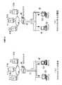
〈〈IGMPv3〉〉
図5は、IGMPv3の概要を示す図である。図5を用いて、IGMPv3について、クライアントE2がマルチキャストグループに参加する場合の処理(図5(a)参照)と、クライアントE2がマルチキャストグループから離脱する場合の処理(図5(b)参照)とを説明する。
【0062】
まず、図5(a)を用いて、クライアントE2がマルチキャストグループに参加する場合の処理について説明する。IGMPv3では、IGMPv1やIGMPv2と同様に、マルチキャストルータM1は、サブネットに対してクエリメッセージを定期的に送信する(1)。マルチキャストグループへの参加を希望するクライアントE2は、クエリメッセージへの応答として、このマルチキャストグループの情報をレポートメッセージに格納して送信する。この時、クライアントE2は、このマルチキャストグループに対するソース(サーバE1(E1a,E1b,E1n))を指定したければ、ソースとなるサーバE1の情報をレポートメッセージに含めて送信することができる(2)。クライアントE2は、あるマルチキャストグループに対して、複数(0以上:例えばサーバE1a及びサーバE1b)のソースとなるサーバE1を指定することができる。
【0063】
このようなソースを指定する方法(フィルタモード)には、INCLUDEモードとEXCLUDEモードの2種類がある。INCLUDEモードでは、クライアントE2は、レポートメッセージで指定されたサーバE1からマルチキャストデータを受信する。一方、EXCLUDEモードでは、クライアントE2は、レポートメッセージで指定されたサーバE1以外のサーバE1からマルチキャストデータを受信する。
【0064】
マルチキャストルータM1は、レポートメッセージを受信すると、このレポートメッセージを受信したインタフェースを介して、このレポートメッセージに対応するマルチキャストデータのうち、このレポートメッセージによって指定されたサーバE1から送信されたマルチキャストデータのみを転送する。このため、マルチキャストルータM1の配下のクライアントE2は、任意の1台以上のサーバE1から送信されたマルチキャストデータのみを受信することができる。
【0065】
マルチキャストルータM1は、あるマルチキャストグループについて、あるクライアントE2にとって新たなサーバE1をソースとしたレポートメッセージを受信した場合、このサーバE1からのマルチキャストデータの転送先について判断(情報のマージ)を行う。この場合、マルチキャストルータM1は、この判断結果を保持することで、このサーバE1から送信されたマルチキャストデータを、該当するクライアントE2へ転送する(即ち、該当するインタフェースから送信する)。
【0066】
IGMPv3では、あるインタフェース配下に、あるマルチキャストアドレスに対してINCLUDEモードを指定したクライアントE2のみが存在する場合、情報のマージの実行により、フィルタモードは”INCLUDE”であり、指定されたサーバE1の全てを含むソースリストが保持される。ここで、ソースリストとは、あるマルチキャストアドレスについてのソースを判断するための、サーバE1のアドレスのリストである。
【0067】
図6は、あるインタフェースi配下にINCLUDEモードを指定したクライアントE2のみが存在する場合の状態を示す図である。例えば、マルチキャストルータM1のあるインタフェースi配下のクライアントE2a,E2b,E2nの状態は、マルチキャストアドレスmに対して、それぞれ(m,INCLUDE,”a,b,c”),(m,INCLUDE,”b,c,d”),(m,INCLUDE,”e,f”)であると仮定する。ここで、(マルチキャストアドレス,フィルタモード,ソースリスト)とする。この場合、マルチキャストルータM1が保持すべき状態は、(i,m,INCLUDE,”a,b,c,d,e,f”)となる。即ち、あるインタフェースi配下の全てのクライアントE2がINCLUDEモードであれば、このインタフェースiについてのフィルタモードの設定はINCLUDEモードになり、ソースリストは各レコードに含まれるソースのマージ(即ちa,b,c,d,e,f)となる。
【0068】
また、あるインタフェース配下に、あるマルチキャストアドレスに対してEXCLUDEモードを指定したクライアントE2が1台でも存在すれば、マルチキャストルータM1が保持するフィルタモードはEXCLUDEモードとなる。そして、マルチキャストルータM1は、INCLUDEモードで指定された全てのソースを除いた、EXCLUDEモードで指定された全てのソースの共通部分を、ソースリストとして保持する。
【0069】
図7は、あるインタフェースi配下にEXCLUDEモードを指定したクライアントE2が存在する場合の状態を示す図である。例えば、マルチキャストルータM1のあるインタフェースi配下のクライアントE2a,E2b,E2nの状態が、マルチキャストアドレスmに対して、それぞれ(m,EXCLUDE,”a,b,c,d”),(m,EXCLUDE,”b,c,d,e”),(m,INCLUDE,”d,e,f”)であると仮定する。この場合、マルチキャストルータM1が保持すべき状態は、(i,m,EXCLUDE,”b,c”)となる。即ち、インタフェースi配下にEXCLUDEモードのクライアントE2(この場合は、E2a,E2b)が存在するため、このインタフェースiのフィルタモードはEXCLUDEモードとなる。そして、このインタフェースiのソースリストは、”b,c”となる。
【0070】
マルチキャストルータM1は、配下の各システムの状態をマージし、その状態を各インタフェースにおいて、マルチキャストアドレス毎に保持する。
【0071】
また、クライアントE2は、ソケット毎に(ソケットが複数存在すれば)インタフェース毎のマルチキャストアドレス毎に、フィルタモードと、対応するソースリストをそれぞれ保持する。
【0072】
次に、図5(b)を用いて、クライアントE2がマルチキャストグループから離脱する場合の処理について説明する。あるマルチキャストグループに参加しているクライアントE2は、このマルチキャストグループに対して、INCLUDEモードでソースリストがエンプティのレポートメッセージを送信する。あるいは、このクライアントE2は、このマルチキャストグループに対して、ソース情報の変更を含めたレポートメッセージを送信する(3)。このレポートメッセージの送信により、このクライアントE2は、このマルチキャストグループから離脱する。
【0073】
マルチキャストルータM1は、このレポートメッセージを受信すると、このレポートメッセージを受信したインタフェース配下について、このレポートメッセージを送信した以外のクライアントE2(他のグループメンバ)の存在を確認する。即ち、マルチキャストルータM1は、このマルチキャストグループに関するGroup Specific Queryを、レポートメッセージを受信したインタフェースを介して送信する。あるいは、マルチキャストルータM1は、ソース情報の変更が含まれたレポートメッセージを受信した場合は、ソース情報が変更されることを確認するGroup and Source Specific Queryを送信する(4)。
【0074】
他のグループメンバが存在する場合、この他のグループメンバは、まだ受信したいことを伝えるため、Group Specific Queryに応答してレポートメッセージを送信する。あるいは、この他のグループメンバは、変更されるソース情報を維持させるためのレポートメッセージを送信する(5)。マルチキャストルータM1は、このレポートメッセージを受信すると、他のグループメンバの存在を認識し、このインタフェースへのマルチキャストデータの転送を継続する。
【0075】
一方、マルチキャストルータM1は、このGroup Specific Queryへの応答としてのレポートメッセージを受信しない場合、即ち他のグループメンバが存在しない場合、このインタフェース配下に他のグループメンバが存在しないと判断し、このインタフェースへのマルチキャストデータの転送を中止する。
【0076】
次に、IGMPv3による、クライアントE2のステート変更の動作について説明する。IGMPv1,IGMPv2では、クライアントE2について、マルチキャストグループへの参加や離脱に関連する動作のみが規定されていた。しかし、IGMPv3では、クライアントE2が、ステートの変更(ソースやフィルタモードの変更)をマルチキャストルータM1へ通知することが可能となった。マルチキャストルータM1は、この通知を受信すると、ステートの変更を反映して動作する。
【0077】
あるマルチキャストグループに参加しているクライアントE2は、このマルチキャストグループにおけるソースやフィルタモードを変更する場合、このマルチキャストグループの情報と、フィルタモードやソースの変更情報とを、レポートメッセージに格納して送信する。
【0078】
マルチキャストルータM1は、このレポートメッセージを受信すると、自身が記憶する情報(例えば情報のマージによる判断結果)に対して、レポートメッセージに含まれるステートの変更を反映するして良いか否かを確認する。このとき、マルチキャストルータM1は、このマルチキャストグループとこのマルチキャストグループに関連するソースリストに関するGroup and Source Specific Queryを送信することにより、上記の確認を行う。このマルチキャストグループに対して変更されようとしているソース情報を維持したいクライアントE2は、その情報を含めたレポートメッセージをマルチキャストルータM1へ送信する。
【0079】
マルチキャストルータM1は、このレポートメッセージを受信すると、必要とされるソースとしてのサーバE1の情報を把握して、該当するソースリストを維持あるいは更新し、適切なサーバE1からのマルチキャストデータを転送する。
【0080】
マルチキャストルータM1は、マルチキャストグループに関するGroup and Source Specific Queryに対するレポートメッセージが受信されない場合、現在の情報に従ってマルチキャストデータの転送を継続する。
【0081】
IGMPv3では、クエリメッセージの受信に関係なく、クライアントE2は、自身のステートが変更(マルチキャストデータの受信中止や、フィルタモードの変更など)された時点で、Unsolicited Reportを送信することが出来る。
【0082】
このように、従来のIGMP(IGMPv1,IGMPv2)では、マルチキャストアドレスのみを基にマルチキャストグループ管理機能が提供されていたのに対し、IGMPv3では一つのマルチキャストアドレスとこのマルチキャストデータのソースとなる0台以上のサーバE1とをセットとして、マルチキャストグループ管理機能が提供される。即ち、クライアントE2は、あるマルチキャストグループに対して、0以上のサーバE1の組を指定してマルチキャストデータの受信要求を行うことが可能となる。言い換えると、あるマルチキャストアドレスに対してサーバE1に制限が付けられなければ(サーバE1の数が0)、従来のIGMPと同じマルチキャストアドレスのみの管理と同等となる。また、サーバE1が(1台以上)指定されれば、マルチキャストアドレスが同じでも指定されたサーバE1以外から送信されるマルチキャストデータは処理(受信や転送など)されない。さらに、同じレポートメッセージにおいて、複数のマルチキャストアドレスとその関連するソースが指定されることが可能である。
【0083】
また、ソースが一つだけ指定されれば、あるマルチキャストセッションはソースSとマルチキャストグループGとを用いて、(S,G)と表現される。このため、同じマルチキャストアドレスGが重複して使用されても、ソースSが異なることで、他のマルチキャストセッションと識別することが可能となる。この形態をSSMと呼ぶ。
【0084】
尚、IGMPではいずれのバージョンもIPv4が対象とされている。IPv6におけるIGMP相当のプロトコルは、MLDとしてIETFのmagma WGにて標準化作業中である。IGMPv2に対応するのがMLD for IPv6(RFC2710)であり、IGMPv3に対応するのがMLDv2 for IPv6(draft-vida-mld-v2-xx.txt)である。
【0085】
IGMP(IGMPv1)は、RFC1112のAPPENDIX Iで規定され、インターネットスタンダード(Internet Standard)となっている。また、IGMPv2はRFC2236で規定され、リーブメッセージが追加されたことにより、IGMPv1に比べて「小さい離脱待ち時間(low leave latency)」に関する機能が加えられている。さらに、IGMPv3は、マルチキャストアドレスと共にソースを指定してグループメンバーシップ情報を管理する「ソースフィルタリング」の機能が追加されており、また、IGMPv1とIGMPv2とに対して相互動作可能なように設計されている。ソースフィルタリングとは、あるシステムがあるマルチキャストアドレスに対して特定のソースから、あるいは特定のソースの組からのみマルチキャストデータを受信することを可能にする機能である。
【0086】
IGMPv3のメッセージは、IPv4データグラムにカプセル化され、IPプロトコル番号は”2”である。各々のIGMPメッセージはIP TTL=1で送信される。これらの規定は、従来のIGMPと同じである。
【0087】
また、IGMPv3のメッセージはIGMPv1の場合と同じく、クエリメッセージとレポートメッセージとが使用される(ただし、当然内容は異なる)。IGMPv2のリーブメッセージに相当する動作は、IGMPv3のレポートメッセージを「受信を希望するソースのリストをエンプティにした状態」で送信することで実現される。また、従来のIGMPのJoin(レポートメッセージの送信)に相当する動作は、IGMPv3のレポートメッセージを「受信を希望しないソースのリストをエンプティにした状態」で送信することで実現される。
【0088】
次に、IGMPv2とIGMPv3との差異を説明する。第一に、IGMPv3では、ソースフィルタリングが導入された。
【0089】
第二に、IGMPv3では、リーブメッセージ(グループ離脱を通知するメッセージ)が仕様から削除された。このため、IGMPv3では、グループ離脱は、該当するマルチキャストグループについて転送を必要とするソースが無いことを示すレポートメッセージを送信することによって実施される。
【0090】
第三に、IGMPv3では、ステート変更の通知が可能となった。即ち、IGMPv3では、クライアントがあるマルチキャストグループに対して、転送を必要とするソースやフィルタモードに変更があった場合に、レポートメッセージによってルータにこの旨を通知することが可能となった。
【0091】
第四に、IGMPv3では、Group and Source Specific Queryが規定された。この規定により、クライアントが、あるマルチキャストグループについて必要とするソースやフィルタモードに変更があったことをレポートメッセージによってマルチキャストルータに通知した時、このマルチキャストルータは、このマルチキャストグループに対するソースの情報変更を反映して良いか否かをインタフェース配下に確認する。
【0092】
第五に、IGMPv3では、IGMPv3ルータは、自身以外にIGMPv2で動作するマルチキャストルータあるいはクライアントが存在した場合は、IGMPv2で動作しなければならないことが規定された。同様に、IGMPv1で動作するマルチキャストルータあるいはクライアントが存在した場合には、IGMPv1で動作しなければならないことが規定された。
【0093】
第六に、IGMPv3では、クライアントによるレポートメッセージの抑制機能が廃止された。即ち、IGMPv3でネットワークが動作している場合、IGMPv1,v2と異なり、レポートメッセージは全てのIGMPv3ルータを示すアドレス”224.0.0.22”へ送信される。この廃止は、ブリッジ/L2スイッチでのIGMP Snoopingを考慮して実施された。
【0094】
第七に、IGMPv3では、IGMPv3ルータは、レポートメッセージが到着したインタフェースにアサインされたあらゆるアドレス(ユニキャストあるいはマルチキャスト)を受信し、レポートメッセージか否かを確認できなければならなくなった。
【0095】
〈マルチキャストルーティングプロトコル〉
図8は、マルチキャストルーティングプロトコルの概要を示す図である。図8を用いてマルチキャストルーティングプロトコルについて説明する。
【0096】
マルチキャストルーティングプロトコルとは、マルチキャストに対応する複数のルータやレイヤ3スイッチ(複数のマルチキャストルータM1)によって構成されるネットワークにおいて、マルチキャストルータM1がマルチキャストデータをクライアントE2への経路に沿って配信するために、マルチキャストルータM1のどのインタフェースへマルチキャストデータをコピーして送信するべきかを決める経路制御(あるいは経路木の構成)のためのプロトコルである。マルチキャストルーティングプロトコルは、マルチキャストルータM1間のプロトコルである。
【0097】
マルチキャストルーティングプロトコルには、DVMRP(MBoneで使用,RFC1075で規定)や、PIM(Protocol Independent Multicast:RFC2362で規定,新たなバージョンがIETFで検討中)、MOSPF(OSFP上でのみ動作可,RFC1584,1585で規定)等がある。このうち、PIMがデファクトスタンダードになっている。
【0098】
〈RFC1112〉
図9は、RFC1112の概要を示す図である。図9を用いて、RFC1112について説明する。RFC1112では、クラスDのIPアドレスと物理アドレスとのマッピングや、特定のクラスDの物理アドレスのパケットのみを受信し上位層へ上げるフィルタリング機能等が規定されている。RFC1112の機能が実施されるためには、ルータ、クライアント共に、RFC1112が実装される必要がある。
【0099】
クラスDのIPアドレスと物理アドレスとの対応付けは、クラスDのIPアドレスの下位23ビットをマルチキャスト物理アドレス”01:00:5E:00:00:00”(16進数)の下位23ビットに入れると規定されている(RFC1700参照)。例えば、”239.133.130.34”は、”01:00:5E:05:82:22”となる。
【0100】
〈IPv6でのマルチキャスト〉
次に、IPv6環境でのマルチキャストについて説明する。IPv6におけるIGMPv3に相当するプロトコルは、MLDv2であり、IETFで検討中である。IGMPとMLDの主な差異は以下の点である。第一に、MLDv2では、IPv4ヘッダでIGMPを示すことはなく、ICMPv6メッセージタイプ(Multicast Listener Query:Type = decimal 130、MLD Version 2 Multicast Listener Report:Type = decimal 131、MLD Version 2 Multicast Listener Done:Type = decimal 132 )を使用する。
【0101】
第二に、MLDv2では、マルチキャストMACアドレスは、128ビットIPv6アドレスの下位32ビットを48ビットのMACアドレス”33:33:xx:xx:xx:xx”へマッピングし生成する。
【0102】
従って、上記のようなIPv4とIPv6マルチキャストの差異を上記に従って認識・区別可能であり、またIGMPv3及びMLDv2の動作に関しては大きな差分はない。また、IPv6に対応可能なPIMのようなマルチキャストルーティングプロトコルも存在する。
【0103】
〔原理〕
〈システム構成〉
次に、図を用いて本発明の転送装置の原理について説明する。図10は、本発明の転送装置が使用された転送システム1を示す図である。転送システム1は、転送装置2,サーバ3,レイヤ2スイッチ4(4a,4b),クライアント5(5a,5b),及びマルチキャスト対応ネットワーク6を用いて構成される。
【0104】
まず、転送装置2以外の構成について説明する。サーバ3は、パーソナルコンピュータやワークステーション等の情報処理装置を用いて構成され、クライアント5に対してマルチキャストデータを送信する。
【0105】
レイヤ2スイッチ4は、複数のクライアント5を収容する。ここでは、レイヤ2スイッチ4aはマルチキャストデータを受信しないクライアント5aを収容し、レイヤ2スイッチ4bはマルチキャストデータを受信するクライアント5bを収容する。
【0106】
クライアント5は、パーソナルコンピュータやワークステーション等の情報処理装置を用いて構成される。ここでは、クライアント5aはサーバ3からマルチキャストデータを受信せず、クライアント5bはサーバ3からマルチキャストデータを受信するように設定される。このため、クライアント5bは、転送装置2に対し、マルチキャスト制御パケットを送信する。即ち、転送装置2,レイヤ2スイッチ4b,クライアント5bの間では、マルチキャスト制御パケットが送受信される。マルチキャスト制御パケットとは、クライアント5bが、マルチキャストデータの受信を望むことあるいは受信を中止すること等を転送装置2へ通知するためのデータである。このようなマルチキャスト制御パケットの例として、IGMPv3メッセージがある。
【0107】
マルチキャスト対応ネットワーク6は、マルチキャストに対応するルータやレイヤ3スイッチを用いて構成されるネットワークである。
【0108】
図11は、転送装置2の原理を示すブロック図である。次に、図11を用いて転送装置2について説明する。転送装置2は、クライアント5bからマルチキャスト制御パケットを受信しその内容を記憶することにより、マルチキャストパケットを転送すべきクライアント5を判別する。そして、転送装置2は、サーバ3からマルチキャストパケットを受信すると、各クライアント5bに対してユニキャストとして、受信されたマルチキャストパケットの内容を転送する。転送装置2は、このような処理を実行するため、送受信インタフェース7(7a,7b),マルチキャストパケット処理部8,及び転送処理部13を用いて構成される。
【0109】
送受信インタフェース7は、ネットワークを介して他の装置とデータの送受信を行う。送受信インタフェース7aは、ネットワークを介してレイヤ2スイッチ4やクライアント5とデータの送受信を行う。ここでは、送受信インタフェース7aは、レイヤ2スイッチ4を介してクライアント5とデータの送受信を行う。通常、転送装置2は、送受信インタフェース7aを複数備える。送受信インタフェース7bは、ネットワーク(マルチキャスト対応ネットワーク6)を介してサーバ3とデータの送受信を行う。
【0110】
マルチキャストパケット処理部8は、送受信インタフェース7a及び送受信インタフェース7b毎に備えられる。または、マルチキャストパケット処理部8は、全ての送受信インタフェース7a,7bについて、一つ備えられる。図11では、便宜上、一つのマルチキャストパケット処理部8が描かれている。マルチキャストパケット処理部8は、対応する送受信インタフェース7aを管理する。マルチキャストパケット処理部8は、自身が管理する送受信インタフェース7配下のクライアント5の中から、送受信インタフェース7bによって受信されたマルチキャストパケットを転送すべきクライアント5を判断する。マルチキャストパケット処理部8は、このような処理を行うために、受信クライアント情報管理テーブル記憶部9,マルチキャスト制御メッセージ判別部10,マルチキャストパケット判別部11,及びデータフレーム生成部12を備える。
【0111】
受信クライアント情報管理テーブル記憶部9は、受信クライアント情報管理テーブル9Aを記憶する。受信クライアント情報管理テーブル9Aは、転送装置2配下の各クライアント5についての情報を格納する。
【0112】
マルチキャスト制御メッセージ判別部10は、送受信インタフェース7aによってクライアント5から受信されたパケットが、マルチキャスト制御パケットであるか否かを判別する。マルチキャスト制御メッセージ判別部10は、受信されたパケットがマルチキャスト制御パケットである場合、このパケットの内容を受信クライアント情報管理テーブル9Aに反映させる。このとき、マルチキャスト制御メッセージ判別部10は、このパケットを転送処理部13へ渡す。一方、受信されたパケットがマルチキャスト制御パケットでない場合、マルチキャスト制御メッセージ判別部10は、このパケットを転送処理部13へ渡す。
【0113】
マルチキャストパケット判別部11は、転送処理部13から受け取られたパケットが、マルチキャストパケットであるか否かを判別する。マルチキャストパケット判別部11は、このパケットがマルチキャストパケットである場合、このパケットをデータフレーム生成部12へ渡す。一方、マルチキャスト判別部11は、このパケットがマルチキャストパケットでない場合、このパケットを送受信インタフェース7aを介して送出する。
【0114】
データフレーム生成部12は、マルチキャストパケット判別部11から受け取られたマルチキャストパケットを基に、送受信インタフェース7a配下のクライアント5(5b)へ送信されるべきユニキャストパケット(クライアント5(5b)へ送信されるべきマルチキャストフレーム)を生成する。
【0115】
転送処理部13は、通常のルータが備えるルーティング処理やマルチキャストルーティング処理などを行う。このため、転送処理部13は、ルーティングテーブル14Aを記憶するルーティングテーブル記憶部14と、マルチキャストルーティング処理を実行するマルチキャスト処理部15とを備える。
【0116】
〈動作例〉
次に、転送装置2の動作例を説明する。送受信インタフェース7aがマルチキャスト制御パケットを受信すると、マルチキャスト制御メッセージ判別部10は、受信されたパケットがマルチキャスト制御メッセージであるか否かを判別(検査)する。マルチキャスト制御メッセージ判別部10は、受信されたパケットがマルチキャスト制御パケットである場合、このパケットの内容を受信クライアント情報管理テーブル9Aに反映させる。また、マルチキャスト制御メッセージ判別部10は、このパケットを転送処理部13へ渡す。そして、転送処理部13は、通常のマルチキャストデータの転送制御情報として受け取ったマルチキャスト制御パケットの内容を、ルーティングテーブル14A及びマルチキャスト処理部15に反映させる。
【0117】
一方、マルチキャスト制御メッセージ判別部10は、受信されたパケットがマルチキャスト制御パケットでない場合、このパケットを転送処理部13へ渡す。そして、転送処理部13は、このパケットについて転送処理を実行する。
【0118】
送受信インタフェース7bがマルチキャストパケットを受信すると、転送処理部13は、受信されたマルチキャストデータをどの送受信インタフェース7aから送出すべきかを判別する。そして、転送処理部13は、判別された送受信インタフェース7aを管理するマルチキャストパケット処理部8へ、受信されたマルチキャストパケットを渡す。
【0119】
転送処理部13からマルチキャストパケット処理部8へ渡されたマルチキャストパケットは、マルチキャストパケット判別部11によって処理される。マルチキャストパケット判別部11は、受信クライアント管理テーブル9Aを参照し、受信されたマルチキャストパケットを転送すべきクライアント5bの存在の有無を確認する。このようなクライアント5bが存在する場合、マルチキャストパケット判別部11は、受信されたマルチキャストパケットをデータフレーム生成部12へ渡す。
【0120】
データフレーム生成部12は、受信されたマルチキャストパケットを、クライアント5b宛のユニキャストパケットに変換し、送受信インタフェース7aを介してクライアント5bへ転送する。このとき、データフレーム生成部12は、必要に応じてユニキャストパケットを複数生成する。例えば、受信されたマルチキャストパケットを転送すべきクライアント5bが複数存在する場合、ユニキャストパケットは複数生成される。
【0121】
一方、このようなクライアント5bが存在しない場合、マルチキャストパケット判別部11は、受信されたマルチキャストパケットを、送受信インタフェース7aを介して他の装置へ転送する。このような他の装置とは、例えば自装置2に接続される、転送装置2や、マルチキャスト対応ルータ等がある。
【0122】
〔実施形態概要〕
次に、図を用いて本発明の実施形態における転送装置、即ちマルチキャストルータ16について説明する。なお、本実施形態の説明は例示であり、本発明の構成は以下の説明に限定されない。また、以下の説明では、IPv4とIGMPv3とが適用されるネットワークを例として説明する。IPv6が適用される場合には、IGMPv3の代わりにMDLv2を適用するなど、上記したIPv4におけるマルチキャストとIPv6におけるマルチキャストとの差分を考慮することにより、同様の手順で本発明を実施することが可能である。
【0123】
図12は、マルチキャストルータ16を用いたマルチキャストシステム17のネットワーク構成を示す図である。マルチキャストシステム17は、サーバ3,マルチキャスト対応ネットワーク6,マルチキャストルータ16,レイヤ2スイッチ4,及び複数のクライアント5を用いて構成される。
【0124】
まず、マルチキャストルータ16以外の構成について説明する。サーバ3,マルチキャスト対応ネットワーク6,レイヤ2スイッチ4,及びクライアント5の基本的な構成は、原理において説明した通りである。
【0125】
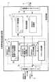
図13は、マルチキャストルータ16の構成を示すブロック図である。図13を用いてマルチキャストルータ16の構成について説明する。マルチキャストルータ16は、ハードウェア的には、バスを介して接続されたCPU,主記憶(RAM),補助記憶装置(フラッシュメモリ)等を備えている。マルチキャストルータ16は、補助記憶装置に記憶された各種のプログラム(OS,アプリケーション等)が主記憶にロードされCPUにより実行されることによって、マルチキャストパケット処理部18(18a,18b,18c),転送制御部19,送受信インタフェース21(21a,21b,21c)等を含む装置として機能する。
【0126】
図14は、マルチキャストパケット処理部18の構成を示すブロック図である。図14を用いてマルチキャストパケット処理部18について説明する。マルチキャストパケット処理部18は、タイマ23,受信クライアント情報管理テーブル記憶部24,マルチキャスト制御メッセージ判別部25,マルチキャストパケット判別部26,及びデータフレーム生成部27を用いて構成される。
【0127】
タイマ23は、計時装置やCPUやRAM等を用いて構成される。タイマ23は、自身が備えられるマルチキャストパケット処理部18に対応する送受信インタフェース21を介してクエリメッセージが送出されると、計時を開始する。タイマ23は、受信クライアント情報管理テーブル24Aの各エントリについて、計時を行う。そして、タイマ23は、このクエリメッセージに対するレポートメッセージが、一定時間内にこの送受信インタフェース21を介して受信されるか否かを判断する。即ち、タイマ23は、受信クライアント情報管理テーブル24Aの各エントリについて、一定時間内にレポートメッセージが受信されるか否かを判断する。タイマ23は、受信クライアント情報管理テーブル24Aのあるエントリについてレポートメッセージが受信されると、このエントリについての計時をリセット(計時の値を0とすること)する。
【0128】
例えば、タイマ23は、クエリメッセージの送信間隔の3倍の時間が設定される。この場合、タイマ23は、クエリメッセージが3回送信される間にレポートメッセージが受信されない場合に、タイムアウトとなる。クエリメッセージの送信間隔が125秒である場合、タイマ23には、375秒が設定される。
【0129】
タイマ23は、タイムアウトとなった場合、このエントリに対応するクライアント5がなんらかの原因によってマルチキャストデータを既に受信していないと判断する。このため、タイマ23は、タイムアウトとなったエントリに対応するクライアント5に関する情報を、受信クライアント管理テーブル24Aから削除する。即ち、タイマ23は、タイムアウトとなったエントリに対応するクライアント5に関するエントリを、受信クライアント管理テーブル24Aから削除する。よって、タイマ23がタイムアウトとなった場合、このエントリに対応するクライアント5へのマルチキャストデータの転送が停止される。
【0130】
タイマ23の処理は、IPv6環境におけるMLDv2の場合であっても、同様に実施される。
【0131】
受信クライアント情報管理テーブル記憶部24は、ハードディスクやフラッシュメモリ等の不揮発性記憶装置を用いて構成される。受信クライアント情報管理テーブル記憶部24は、受信クライアント情報管理テーブル24Aを記憶する。
【0132】
図15は、受信クライアント情報管理テーブル24Aの例を示す図である。図15を用いて、受信クライアント情報管理テーブル24Aについて説明する。
【0133】
受信クライアント情報管理テーブル24Aは、各クライアント5がどのマルチキャストデータを受信したいかを判断するために必要となる情報を管理する。受信クライアント情報管理テーブル24Aは、各クライアント5から送出され自身が対応する送受信インタフェース21を介して受信されるレポートメッセージに含まれる情報を基に作成・更新される。受信クライアント情報管理テーブル24Aは、ローカルなインタフェース情報であるため、MACアドレスも格納される。
【0134】
受信クライアント情報管理テーブル24Aは、エントリナンバー,クライアントアドレス(Client Address),クライアントMACアドレス(Client MAC Address),マルチキャストアドレス(Multicast Address),ソースアドレス(Source Address),フィルタモード(Filter Mode)を項目とするエントリを持つ。
【0135】
エントリナンバーは、各エントリに割り当てられる重複しない数字である。図15に示される受信クライアント情報管理テーブル24Aでは、クライアントアドレス毎に一つのエントリナンバーが与えられる。即ち、図15に示される受信クライアント情報管理テーブル24Aでは、一つのクライアントアドレスに対して、複数の(1以上の)マルチキャストアドレス,ソースアドレス,フィルタモードが与えられる。
【0136】
クライアントアドレスは、受信クライアント情報管理テーブル記憶部24が備えられるマルチキャストパケット処理部18に対応する送受信インタフェース21配下に位置するクライアント5のIPアドレスを示す。
【0137】
クライアントMACアドレスは、同じエントリのクライアントアドレスに対応するMACアドレスを示す。即ち、クライアントMACアドレスは、同じエントリのクライアントアドレスを有するクライアント5のMACアドレスを示す。
【0138】
マルチキャストアドレスは、同じエントリのクライアントアドレスを有するクライアント5が受信を希望するマルチキャストデータのマルチキャストアドレスを示す。マルチキャストアドレスは、一つのエントリに複数保持される場合がある(例:図15におけるエントリナンバー1)。
【0139】
ソースアドレスは、対応するマルチキャストアドレスについてのマルチキャストデータの送信元となるサーバ3のアドレス(IPアドレス)を示す。マルチキャストルータ16は、IGMPv3に対応する。このため、ソースアドレスは、一つのマルチキャストアドレスに対して複数保持される場合がある(例:図15におけるエントリナンバー1)。
【0140】
フィルタモードは、対応するマルチキャストアドレスについてのフィルタモードを示す。フィルタモードは、”INCLUDE”と”EXCLUDE”とのいずれかの値を持つ。
【0141】
ここで、マルチキャストアドレス”238.0.0.123”を例として、受信クライアント情報管理テーブル24Aについて説明する。図15に示される受信クライアント情報管理テーブル24Aは、以下の情報を持つ。
【0142】
”61.143.221.2”がソースアドレスであるマルチキャストデータは、”210.23.171.aa”をアドレスとするクライアント5と”210.23.171.ff”をアドレスとするクライアント5とが受信を希望している。”61.143.221.3”がソースアドレスであるマルチキャストデータは、”210.23.171.aa”をアドレスとするクライアント5と”210.23.171.dd”をアドレスとするクライアント5と”210.23.171.ff”をアドレスとするクライアント5とが受信を希望している。”61.143.221.4”がソースアドレスであるマルチキャストデータは、”210.23.171.aa”をアドレスとするクライアント5と”210.23.171.dd”をアドレスとするクライアント5とが受信を希望している。”61.143.221.5”がソースアドレスであるマルチキャストデータは、”210.23.171.ff”をアドレスとするクライアント5が受信を希望している。そして、上記以外のソースアドレスであるマルチキャストデータは、”210.23.171.dd”をアドレスとするクライアント5が受信を希望している。また、エントリナンバー1のエントリにおけるクライアント5は、マルチキャストアドレス”238.0.0.123”宛のマルチキャストデータを、ソースアドレスが”61.143.221.2”,”61.143.221.3”,”61.143.221.4”であるサーバ3から送信された場合にのみ受信する。
【0143】
マルチキャスト制御メッセージ判別部25は、CPUやRAM等を用いて構成される。マルチキャスト制御メッセージ判別部25は、自身が備えられるマルチキャストパケット処理部18に対応する送受信インタフェース21を介して受信されたパケットが、マルチキャスト制御パケットであるか否かを判別する。即ち、マルチキャスト制御メッセージ判別部25は、対応する送受信インタフェース21を介して受信されたパケットが、マルチキャスト制御メッセージ(クライアント5が自発的に送信するIGMPレポートやリーブメッセージ,レポートメッセージなど)を含むパケットであるか否かを判別する。マルチキャスト制御メッセージ判別部25は、受信されたパケットがマルチキャスト制御パケットである場合、対応する送受信インタフェース21配下に、マルチキャストデータの受信を希望するクライアント5が存在することを認識する。マルチキャスト制御メッセージ判別部25は、受信されたパケットがマルチキャスト制御パケットである場合、このパケットの内容を受信クライアント情報管理テーブル24Aに反映させる(パケットの内容に応じて受信クライアント情報管理テーブル24Aの内容を更新あるいは変更する)。このとき、マルチキャスト制御メッセージ判別部25は、このパケットを転送制御部19へも渡す。一方、受信されたパケットがマルチキャスト制御パケットでない場合、マルチキャスト制御メッセージ判別部25は、このパケットを転送制御部19へ渡す。
【0144】
マルチキャスト制御メッセージ判別部25は、例えばレポートメッセージ(IGMP Report)を含むパケットをマルチキャスト制御パケットであると判断し、処理を実行する。ここで、レポートメッセージについて説明する。
【0145】
レポートメッセージは、IGMPメッセージ又はMLDv2メッセージによる制御メッセージである。図16,17は、IGMPメッセージを含むパケット,MLDv2メッセージを含むパケットのフォーマットを示す図である。図16,17では、データリンク層がイーサネットであると仮定している。IGMPメッセージは、IPパケットのデータグラムとして、IPパケットに保持される。MLDv2メッセージも同様に、IPパケットのデータグラムとしてIPパケットに保持される。
【0146】
レポートメッセージは、IPアドレスが”224.0.0.22”であり、MACアドレスが”01:00:5E:00:00:16”であり、IPヘッダ内のプロトコル番号がIGMPを示す”2”であり、IGMPメッセージのタイプ値が”0x22”である。図18,19は、IPv4,IPv6のパケットのヘッダフォーマットを示す図である。図18におけるProtocol IDの値が”2”である場合に、このパケットがIGMPメッセージを含むパケットであると判別される。このため、これらの情報を基に、マルチキャスト制御メッセージ判別部25は、受信されたパケットが、IGMPメッセージを含むか否か、さらにはレポートメッセージを含むか否かを判別する。
【0147】
図20,21は、IGMPv3,MLDv2におけるレポートメッセージのフォーマットを示す図である。レポートメッセージは、このレポートメッセージの送信元であるクライアント5が受信を希望するマルチキャストデータのマルチキャストアドレス(グループアドレス:Multicast Address)と、受信を希望するマルチキャストデータの送信元となるサーバ3のアドレス(ソースアドレス:Source Address)のリスト(ソースリスト)と、フィルタモードとを含む。
【0148】
例えば、「マルチキャストアドレス”238.0.1.12”のマルチキャストデータをソース”162.22.36.5”と”162.22.36.6”とから受信する」ことを意味するレポートメッセージは、マルチキャストアドレスは”238.0.1.12”、ソースアドレスは”162.22.36.5”と”162.22.36.6”、フィルタモードは”INCLUDE”となる。
【0149】
また、例えば、「マルチキャストアドレス”238.0.1.12”のマルチキャストデータをソース”162.22.36.5”,”162.22.36.6”以外から受信する」ことを意味するレポートメッセージは、マルチキャストアドレスは”238.0.1.12”、ソースアドレスは”162.22.36.5”と”162.22.36.6”、フィルタモードは”EXCLUDE”となる。クライアント5は、単一のレポートメッセージにおいて、複数のマルチキャストアドレスを指定でき、さらにそれぞれのマルチキャストアドレスに対するソースアドレスのリストとフィルタモードとを指定できる。
【0150】
レポートメッセージについての説明を終え、マルチキャスト制御メッセージ判別部25の説明に戻る。次に、マルチキャスト制御メッセージ判別部25が実行する、エントリの追加処理について説明する。マルチキャスト制御メッセージ判別部25は、受信クライアント情報管理テーブル24Aのエントリとして記録されていない新たなクライアント5からのレポートメッセージを受け取った場合、このレポートメッセージに含まれる情報を基に新たなエントリを生成する。このとき、マルチキャスト制御メッセージ判別部25は、レポートメッセージを含むパケットの送信元アドレスと、受信クライアント情報管理テーブル24Aのクライアントアドレスとを比較することにより、新たなクライアント5を識別する。
【0151】
図22は、受信クライアント情報管理テーブル24Aに保持されるエントリの例を示す図である。例えば、図15に示される受信クライアント情報管理テーブル24Aが保持されている状態で、IPアドレスが”210.23.171.gg”であるクライアント5からレポートメッセージが受信された場合、図22に示される新たなエントリが受信クライアント情報管理テーブル24Aに登録される。このとき、このレポートメッセージには、クライアント5のMACアドレスとして”xx:xx:xx:xx:45:67”,ソースアドレスとして”61.143.221.38”,マルチキャストアドレスとして”238.0.2.222”,フィルタモードとして”INCLUDE”が含まれていると仮定する。
【0152】
次に、マルチキャスト制御メッセージ判別部25が実行する、エントリの更新処理について説明する。マルチキャスト制御メッセージ判別部25は、レポートメッセージの内容と、受信クライアント情報管理テーブル24Aにおけるエントリの内容とが異なる場合、エントリの更新処理を行う。
【0153】
例えば、アドレスが”210.23.171.aa”であるクライアント5から、フィルタモードとして”EXCLUDE”,ソースアドレスとして”61.143.221.2”,マルチキャストアドレスとして”238.0.0.123”が指定されたレポートメッセージが受信されたと仮定する。この場合、このレポートメッセージの内容と、受信クライアント情報管理テーブル24Aの内容とが異なる。従って、マルチキャスト制御メッセージ判別部25は、受信クライアント情報管理テーブル24Aの内容を更新する。
【0154】
図23は、受信クライアント情報管理テーブル24Aに保持されるエントリの例を示す図である。上記のレポートメッセージが受信された場合、マルチキャスト制御メッセージ判別部25は、図15に示されるエントリナンバー1の内容を、図23に示される内容に更新する。この更新の結果、マルチキャストルータ16は、アドレスが”210.23.171.aa”であるクライアント5に対し、マルチキャストアドレスが”238.0.0.123”であるマルチキャストデータであって、ソースアドレスが”61.143.221.2”であるサーバ3以外から送出されたマルチキャストデータを転送する。
【0155】
また、フィルタモードが”INCLUDE”であり、ソースアドレスを含まない(エンプティである)レポートメッセージが受信された場合、マルチキャスト制御メッセージ判別部25は、このレポートメッセージに含まれるマルチキャストアドレスを含む情報をエントリから削除する。即ち、このようなレポートメッセージが受信された場合、マルチキャスト制御メッセージ判別部25は、このレポートメッセージの送信元であるクライアント5に対し、このレポートメッセージに含まれるマルチキャストアドレスのマルチキャストデータを転送しないようにエントリを更新する。
【0156】
例えば、アドレスが”210.23.171.bb”であるクライアント5から、マルチキャストアドレスが”238.225.13.33”であり、ソースアドレスがエンプティであり、フィルタモードが”INCLUDE”であるレポートメッセージが受信されたと仮定する。この場合、マルチキャスト制御メッセージ判別部25は、このクライアント5に対し、マルチキャストアドレスが”238.225.13.33”であるマルチキャストデータの転送を停止(中止)すると判断する。即ち、マルチキャスト制御メッセージ判別部25は、クライアントアドレスが”210.23.171.bb”であるエントリから、マルチキャストアドレスが”238.225.13.33”である情報を削除する。図15に示される受信クライアント情報管理テーブル24Aでは、結果として、エントリナンバー2のエントリが全て削除される。この処理は、IPv6環境におけるMLDv2においても同様に実行される。
【0157】
次に、IPv6環境におけるマルチキャスト制御メッセージ判別部25の動作について説明する。IPv6環境におけるMLDv2に対応したネットワークでは、マルチキャスト制御メッセージ判別部25は、MACアドレスがマルチキャストMACアドレスでさらに”33:33:00:00:00:22”であり、IPヘッダ内のネクストヘッダフィールドの値が”58”であり、ヘッダ内のタイプ値が”136(二進数)”であるパケットを、MLDv2におけるレポートメッセージを含むパケットであると判別する。このため、レイヤ2スイッチ4がMLDv2 Snoopingをサポートしていない場合であり、かつマルチキャストルータ16配下のサブネットワークにおいてMLDv2が適用される環境であっても、マルチキャストデータを必要とするクライアント5のみにマルチキャストデータを転送することが可能となる。
【0158】
マルチキャストパケット判別部26は、CPUやRAM等を用いて構成される。マルチキャストパケット判別部26は、転送制御部19から受け取られたパケットが、マルチキャストパケットであるか否かを判別する。マルチキャストパケット判別部26は、このパケットがマルチキャストパケットである場合、このパケットをデータフレーム生成部27へ渡す。
【0159】
一方、マルチキャスト判別部26は、このパケットがマルチキャストパケットでない場合、このパケットを送受信インタフェース21を介して送出する。このようなパケットの例として、通常のユニキャストデータや、マルチキャストデータのうちマルチキャストルーティングプロトコルのメッセージ等がある。
【0160】
データフレーム生成部27は、CPUやRAM等を用いて構成される。データフレーム生成部27は、マルチキャストパケット判別部26によってマルチキャストパケットであると判別されたパケットを、マルチキャストパケット判別部26から受け取る。データフレーム生成部27は、受け取られたマルチキャストパケットのマルチキャストアドレス及びソースアドレス(送信元のサーバ3のアドレス)を参照する。データフレーム生成部27は、参照結果のマルチキャストアドレス及びソースアドレスに該当するエントリを、受信クライアント情報管理テーブル24Aから読み出す。データフレーム生成部27は、受け取られたマルチキャストパケットを変更・コピーすることにより、読み出されたエントリのクライアントアドレス(クライアントMACアドレス)宛のユニキャストパケットを生成する。このとき、データフレーム生成部27は、受け取られたマルチキャストパケットにおける宛先MACアドレスを、マルチキャストMACアドレスから、読み出されたエントリに含まれるクライアントMACアドレスに変更する。そして、データフレーム生成部27は、生成されたユニキャストパケットを、送受信インタフェース21を介して送出する。
【0161】
図24は、データフレーム生成部27の動作例を示すフローチャートである。図24を用いて、データフレーム生成部27の動作について説明する。
【0162】
例えば、アドレスが”61.143.221.2”であるサーバ3から送信されたマルチキャストデータ(マルチキャストアドレスは”238.0.0.123”)が、マルチキャストルータ16によって受信された場合、データフレーム生成部27はマルチキャストパケット判別部26からこのマルチキャストデータを受け取る(S01)。
【0163】
データフレーム生成部27は、受け取られたマルチキャストデータに関するエントリが、受信クライアント情報管理テーブル24Aにあるか否かを判断する。即ち、データフレーム生成部27は、このマルチキャストデータのマルチキャストアドレス及びソースアドレス(フィルタモードが”INCLUDE”である場合は該当するソースアドレスを含むエントリ、フィルタモードが”EXCLUDE”である場合は該当するソースアドレスを含まないエントリ)について、受信クライアント情報管理テーブル24Aを検索する(S02)。
【0164】
受け取られたマルチキャストデータに関するエントリが受信クライアント情報管理テーブル24Aに無い場合(S03−NO)、データフレーム生成部27は、このマルチキャストデータをそのままの状態で(即ちオリジナルのマルチキャストデータを)、送受信インタフェース21を介して送出し、処理を終了する(S04)。
【0165】
一方、受け取られたマルチキャストデータに関するエントリが受信クライアント情報管理テーブル24Aに有る場合(S03−YES)、データフレーム生成部27は、このマルチキャストデータの受信を要求している各クライアント5に対し、このマルチキャストデータをユニキャスト送信する(S05)。
【0166】
上記した例では、受信されたマルチキャストデータのマルチキャストアドレス”238.0.0.123”は、受信クライアント情報管理テーブル24Aのエントリナンバー1,4にある。そして、フィルタモード及びソースアドレスが考慮されると、結果として、エントリナンバー1に該当するクライアント5に対して、受信されたマルチキャストデータが転送されるべきと、データフレーム生成部27は判断する。このため、受信されたマルチキャストデータは、エントリナンバー1に該当するクライアント5に対して、ユニキャスト送信される。
【0167】
具体的には、データフレーム生成部27は、該当するこのエントリを確認すると、このエントリに含まれるクライアントMACアドレスを読み出す。即ち、図15においては、データフレーム生成部27は、”xx:xx:xx:xx:12:34”を読み出す。次に、データフレーム生成部27は、受信されたマルチキャストデータの送信先MACアドレスに対し、読み出されたクライアントMACアドレスを付与しユニキャストデータを生成する。このとき、データフレーム生成部27は、複数のクライアントMACアドレスを読み出した場合、受信されたマルチキャストデータをコピーすることにより、読み出されたクライアントMACアドレスと同数のユニキャストデータを生成する。上記した例では、一つのクライアントMACアドレスが読み出されるため、データフレーム生成部27は、マルチキャストデータを一つコピーし、MACアドレスの変更を実行することによりユニキャストデータを生成する。データフレーム生成部27は、生成されたユニキャストデータを、送受信インタフェース21を介して送出する。そして、データフレーム生成部27は、このマルチキャストデータをそのままの状態で(即ちオリジナルのマルチキャストデータを)、送受信インタフェース21を介して送出し、処理を終了する(S06)。
【0168】
上述したように、データフレーム生成部27は、ユニキャストデータの転送処理を実行するか否かに関わらず、オリジナルのマルチキャストデータを送信する。図25は、オリジナルのマルチキャストデータの送信処理の作用を説明するための図である。図25では、マルチキャストルータ16bは、レイヤ2スイッチ4を介して、上流に位置するマルチキャストルータ16aに接続される。このように接続されたマルチキャストルータ16bは、配下に接続されるクライアント5bに対して正しくマルチキャストデータを配信するため、オリジナルのマルチキャストデータを必要とする。このため、マルチキャストルータ16aのデータフレーム生成部27は、ユニキャストデータの転送処理を実行するか否かに関わらず、オリジナルのマルチキャストデータを送信する。通常、レイヤ2スイッチ4は、あるポートから入力されたマルチキャストパケットをマルチキャストルータが接続されるポート(例えば、マルチキャストルータ16bが接続されるポート)、あるいはその方向のポートを介して送出する。このため、他のマルチキャストルータ(マルチキャストルータ16b)に対し、オリジナルのマルチキャストデータが伝達される。
【0169】
送受信インタフェース21は、ネットワークを介して他の装置とデータの送受信を行う。送受信インタフェース21aは、ネットワーク(マルチキャスト対応ネットワーク6)を介してサーバ3とデータの送受信を行う。送受信インタフェース21b,21cは、サブネットワークやレイヤ2スイッチ4を介してクライアント5や、他のマルチキャストルータ16とデータの送受信を行う。
【0170】
転送制御部19は、通常のルータが備えるルーティング処理やマルチキャストルーティング処理などを行う。このため、転送処理部19は、ルーティングデーブル20Aを記憶するルーティングテーブル記憶部20と、マルチキャストルーティング処理を実行するマルチキャスト処理部22とを備える。
【0171】
〔作用/効果〕
本発明によるマルチキャストルータ16によれば、受信クライアント情報管理テーブル24Aが、IGMPv3メッセージに基づいて、各クライアント5についてのマルチキャストデータの受信設定を保持する。そして、データフレーム生成部27が、受信クライアント情報管理テーブル24Aの内容に基づいて、受信されたマルチキャストデータを、ユニキャストデータとして、このマルチキャストデータを受信するように設定されているクライアント5に対してユニキャスト送信する。
【0172】
このため、マルチキャストルータ16とクライアント5との間に設置されるレイヤ2スイッチ4は、マルチキャストルータ16から送信されたユニキャストデータを、レイヤ2の情報に基づいて転送することが可能となる。即ち、レイヤ2スイッチ4は、レイヤ3レベルの処理が要求されるIGMPv3に基づいて処理を行う必要がなくなる。従って、レイヤ2スイッチ4は、転送能力の低下を招くIGMPv3対応Snoopingを実装される必要が無くなる。よって、IGMPv3対応Snoopingの実装によるコストを削減することや、転送能力の低下を防止することが可能となる。
【0173】
言い換えれば、マルチキャストルータ16の下流に存するレイヤ2スイッチ4が、レイヤ2に基づくスイッチング動作によって、このレイヤ2スイッチ4が収容している1以上のクライアント5のうち、マルチキャストデータの受信を所望するクライアント5のみにマルチキャストデータを転送することが可能となる。
【0174】
また、データフレーム生成部27は、マルチキャストデータをユニキャストデータとして転送するか否かに関わらず、必ずオリジナルのマルチキャストデータを転送する。このため、自装置16配下に設置される他のマルチキャストルータ16に対して、オリジナルのマルチキャストデータを転送することが可能となる。従って、他のマルチキャストルータ16は、オリジナルのマルチキャストデータに基づいて、自装置16の配下に設置される複数のクライアント5それぞれに対して、ユニキャストデータを正しく転送することが可能となる。
【0175】
また、タイマ23は、タイムアウトとなったエントリに対応するクライアント5に関するエントリを、受信クライアント管理テーブル24Aから削除する。このため、クライアント5が問題の発生(例:突然の電源断,OSのハングアップ)によりマルチキャストデータの受信をできなくなった場合、このクライアント5へのマルチキャストデータの転送が停止される。従って、ネットワーク帯域の浪費を防止することが可能となる。即ち、無駄なマルチキャストデータの転送処理の実行を防止することが可能となる。
【0176】
〔変形例〕
送受信インタフェース21は、クライアント側に二つ備えられているが(送受信インタフェース21b,21c)、二つに限らず三つ以上又は一つのみが備えられるように構成されても良い。
【0177】
また、マルチキャストパケット処理部18は、送受信インタフェース21毎に備えられているが、全ての送受信インタフェースを管理する一つのマルチキャストパケット処理部18が備えられるように構成されても良い。
【0178】
また、データフレーム生成部27は、どのような判断手順によってクライアントMACアドレスを読み出すように構成されても良い。
【0179】
また、マルチキャスト制御メッセージ判別部25は、IGMPv1又はIGMPv2に対応するレポートメッセージやクエリメッセージを受信した場合に、受信クライアント情報管理テーブル24Aを、IGMPv1又はIGMPv2に対応するように変換するように構成されても良い。そして、データフレーム生成部27は、変換された受信クライアント情報管理テーブル24Aを参照して、マルチキャストデータに対応するユニキャストデータを生成、送信する。即ち、この場合、データフレーム生成部27を含むマルチキャストパケット処理部18は、IGMPv1又はIGMPv2に対応して動作する。
【0180】
マルチキャストルータ16は、本発明による転送装置の構成が、IPレベルの中継処理を行う一般的なマルチキャストルータやレイヤ3スイッチに実装されることにより構成される。しかし、本発明による転送装置の構成が、専用装置として実装されても良い。
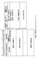
【0181】
図26は、本発明による転送装置の構成が専用装置29として実装された場合のネットワークの構成例を示す図である。このネットワークは、配信センタ28,専用装置29,EPON(Ethernet Passive Optical Network)32,カプラ33,ユーザ宅36を用いて構成される。配信センタ28内には、コンテンツサーバ31が設置される。また、ユーザ宅36内には、メディアコンバータ34とクライアント35とが設置される。また、専用装置29は、マルチキャスト対応ネットワーク30に接続されるルータ37とクライアント35との間に設置される。
【0182】
専用装置29は、ルータ37とクライアント35とから送信されるIGMPメッセージを参照し、受信クライアント情報管理テーブル24A(図15参照)を生成する。また、専用装置29は、ルータ37から送信されるマルチキャストデータを受信し、受信クライアント情報管理テーブル24Aに基づいて、データフレーム生成部27によって、ユニキャストデータを生成しクライアント35へ送信する。
【0183】
このように専用装置29を設置することにより、本発明による転送装置が実装された新たなマルチキャストルータ16を設置する必要がなくなり、ルータ37等の既存設備を活用することが可能となる。例えば、ルータ37がIGMPv3に対応していない場合であっても、ソフトウェアのアップグレード等により、IGMPv3に対応させることが可能である。このため、IGMPv1やIGMPv2にのみ対応していたネットワークについても、専用装置29の設置とソフトウェアのアップグレード等により、IGMPv3に対応したネットワークを構成することが可能となり、このようなネットワーク構成に費やすコストの削減が可能となる。
【0184】
また、FTTH(Fiber To The Home)では、EPON32の性質上、IGMP Snoopingの機能は、メディアコンバータ34に実装されなければならない。しかし、通常は、小型でCPU等も備えないメディアコンバータ34に対して、本発明による転送装置を実装することは困難である。このような場合に、専用装置29が図26に示されるように設置されることにより、他のシステムには影響を与えることなく、IGMPv3によるマルチキャストが可能となる。
【0185】
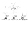
〔適用例〕
本発明による転送装置(転送装置が実装されたマルチキャストルータ16や専用装置29など)は、コンテンツ配信システムに適用されることにより、新たな効果を奏する。図27は、マルチキャストルータ16が適用されたコンテンツ配信システム38の概要を示す図である。コンテンツ配信システム38は、コンテンツ配信ネットワーク(CDN:Contents Distribution Network)事業者のサーバサイト39,ISPの制御センタ44,ISPのネットワーク45,マルチキャストルータ16,クライアント5,レイヤ2スイッチ4を用いて構成される。サーバサイト39は、ユーザ管理/認証サーバ40,課金サーバ41,マルチキャストコンテンツ配信サーバ42,及びルータ43を用いて構成される。また、ISPのネットワーク45は、マルチキャストルータ16を含む。さらに、レイヤ2スイッチ4は、マルチキャストルータ16を介してISPのネットワーク45に接続される。
【0186】
図27に示されるコンテンツ配信システム38では、CDN事業者とISPとの間で、コンテンツ配信依頼/契約が行われる(1)。その後、CDN事業者のマルチキャストコンテンツ配信サーバ42からコンテンツのマルチキャスト配信が実施される(2)。マルチキャストルータ16は、受信クライアント情報について収集・保持・管理を行い(3)、受信クライアント情報をCDN事業者のサイトへ送信する(4)。この受信クライアント情報を受信したCDN事業者は、契約しているISPへ、受信されたユーザ情報と課金情報とを通知する(5)。そして、ISPによって、ユーザに対するコンテンツ受信状況に応じた料金請求が実施される(6)。
【0187】
ユーザ管理/認証サーバ40は、ユーザ管理テーブル46を記憶する。ユーザ管理/認証サーバ40は、ISPのネットワーク45に設置されたマルチキャストルータ16から送信されるクライアント情報を基に、ユーザ管理テーブル46を作成/更新する。クライアント情報は、受信クライアント情報管理テーブル24Aに保持される情報を含む。
【0188】
図28は、ユーザ管理テーブル46の例を示す図である。ユーザ管理テーブル46は、ユーザ名,ユーザアドレス(クライアントアドレス),受信コンテンツアドレス(マルチキャストアドレス),受信開始時間,受信終了時間を項目として有する。
【0189】
ユーザ名は、クライアント5のユーザの名前を示す。ユーザ名は、ユーザを識別するために使用されるため、ユーザID等によって代替されても良い。
【0190】
ユーザアドレスは、クライアント5に割り当てられたアドレスであり、受信クライアント情報管理テーブル24Aにおけるクライアントアドレスと対応する。ユーザアドレスは、受信クライアント情報管理テーブル24AにおけるクライアントMACアドレスと対応しても良い。また、ユーザ名とユーザアドレスとの対応付けは、ISPのDHCP(Dynamic Host Configuration Protocol)サーバのログ情報を参照することや、ユーザ管理/認証サーバ40とDHCPサーバとが連動することで可能となる。
【0191】
受信コンテンツアドレスは、クライアント5が受信したコンテンツについてのマルチキャストアドレスであり、受信クライアント情報管理テーブル24Aにおけるマルチキャストアドレスに対応する。このとき、クライアント5は、マルチキャストコンテンツ配信サーバ42によって配信されるマルチキャストデータをコンテンツとして受信する。
【0192】
受信開始時間と受信終了時間とは、クライアント5が、対応するマルチキャストアドレスについてのマルチキャストデータの受信を開始した時間と受信を終了した時間を示す。
【0193】
CDN事業者は、ユーザ管理テーブル46の情報を基に、サービスを提供することが可能である。図29は、ユーザ管理テーブル46の情報を基に実施されるサービスの例を示す図である。
【0194】
図29では、CDN事業者がサービスを実施する。CDN事業者は、コンテンツ制作会社やISP等の契約ユーザ向けのコンテンツ配信システムを提供するビジネスを行う。ここでは特に、CDN事業者は、マルチキャストによるコンテンツ配信システムを提供すると仮定する。
【0195】
CDN事業者は、サービスメニューとして、通常のマルチキャストによるコンテンツ配信のサービスと、マルチキャストによるコンテンツ配信に加えてユーザ管理を含むサービスとを設定する。このとき、ユーザ管理を含むサービスでは、ユーザ管理テーブル46に保持される情報に基づいたサービスが提供される。例えば、CDN事業者は、ユーザ管理テーブル46に基づいて、ユーザ毎の受信コンテンツとその受信時間等を、コンテンツ制作会社やISPに提供する。
【0196】
従来のマルチキャストでは、サーバは、コンテンツのデータに対し単にマルチキャストアドレスを付与して送信する処理のみを実施していた。また、従来のマルチキャストでは、UDP(User Datagram Protocol)が使用されていたため、TCP(Transmission Control Protocol)が使用された場合と異なり、基本的にどのクライアントがどのマルチキャストデータを受信しているかについては把握できなかった。従って、従来のマルチキャストによるコンテンツ配信では、ユーザ管理やコンテンツの視聴状況を把握することができなかった。
【0197】
しかし、CDN事業者によって提供される情報により、コンテンツ制作会社やISPは、ユーザ管理やコンテンツの視聴状況を把握することが可能となり、ユーザ毎の時間課金や、視聴率の算出等を実施することが可能となる。
【0198】
なお、このサービスは、CDN事業者ではなく、ISP自身によって実施されても良い。また、CDN事業者がネットワークシステム自体を提供し、コンテンツ制作会社の作成したコンテンツの代行配信を実施するという形態でこのサービスが実施されても良い。
【0199】
〔その他〕
本発明は、以下のように特定することができる。
(付記1) 第一のレイヤのデータに基づいてハードウェア的にスイッチングを行うスイッチング装置よりも上流に設置されるデータ生成装置であって、
前記第一のレイヤよりも高次である第二のレイヤのデータから、転送データの転送処理に関する転送管理情報を読み出す読出手段と、
前記読出手段によって読み出される前記転送管理情報を記憶する記憶手段と、前記記憶手段が記憶する前記転送管理情報に基づいて転送データの転送先となるクライアントを判断し、転送先となるクライアント数と同数の、それぞれのクライアントに対して送信される、受信された転送データと同等の内容を含む送信データを生成するデータ生成手段と、
前記データ生成手段によって生成された送信データを前記スイッチング装置へ転送する転送手段と
を備えるデータ生成装置。
(付記2) 前記データ生成手段は、さらに前記転送データにおける前記第二のレイヤのデータに基づいて転送先となるクライアントを判断する付記1に記載のデータ生成装置。
(付記3) 前記データ生成手段は、前記第一のレイヤの送信先アドレスに、前記転送先となるクライアントのアドレスを書き込むことにより前記送信データを生成する付記1又は2に記載のデータ生成装置。
(付記4) レイヤ2よりも高次のレイヤのデータから、マルチキャストデータの転送処理に関する情報を読み出す読出手段と、
前記読出手段によって読み出された情報に基づいた転送管理情報を記憶する記憶手段と、
前記記憶手段が記憶する前記転送管理情報に基づいてマルチキャストデータの転送先となるクライアントを判断し、受信されたマルチキャストデータを、転送先となるクライアント数と同数のデータにコピーし、コピーされた夫々のデータをユニキャストデータに変更するデータ生成手段と
を備えるデータ生成装置。
(付記5) 前記データ生成手段は、さらに前記マルチキャストデータにおけるレイヤ2よりも高次のレイヤのデータに基づいて転送先となるクライアントを判断する付記4に記載のデータ生成装置。
(付記6) 前記データ生成手段は、前記コピーされた夫々のデータのMACアドレスを、転送先となる各クライアントのMACアドレスに書き換えることによりユニキャストデータを生成する付記4又は5に記載のデータ生成装置。
(付記7) 自装置よりも下流側にデータを送出する送出手段をさらに備え、
前記送出手段は、前記データ生成手段によって生成されるユニキャストデータ及び受信されたマルチキャストデータを送出する
付記4〜6のいずれかに記載のデータ生成装置。
(付記8) 前記読出手段によって読み出された情報に基づいて、前記記憶手段に記憶される前記転送管理情報を更新する管理手段をさらに備える付記4〜7のいずれかに記載のデータ生成装置。
(付記9) 前記読出手段によって読み出された情報がマルチキャストグループへの加入を示す情報である場合、前記管理手段はこの情報の内容を前記記憶手段に記憶される前記転送管理情報に反映させる付記8に記載のデータ生成装置。
(付記10) 前記読出手段によって読み出された情報がマルチキャストグループからの離脱を示す情報である場合、前記管理手段はこの情報の送信元であるクライアントに関する情報を前記転送管理情報から削除する付記9に記載のデータ生成装置。
(付記11) 一定時間を計時する計時手段をさらに備え、
前記計時手段が、応答要求に対する応答がクライアントから一定時間以上受信されていないと判断した場合、前記管理手段はこのクライアントに関する情報を前記転送管理情報から削除する付記9又は10に記載のデータ生成装置。
(付記12) 前記読出手段は、IGMP(Internet Group Management Protocol)バージョン3のメッセージから前記情報を読み出す付記4〜11のいずれかに記載のデータ生成装置。
(付記13) 前記読出手段は、MLD(Multicast Listener Discovery)バージョン2のメッセージから前記情報を読み出す付記4〜11のいずれかに記載のデータ生成装置。
(付記14) 前記管理手段は、IGMPバージョン1又はIGMPバージョン2のメッセージが受信された場合、前記転送管理情報をIGMPバージョン1又はIGMPバージョン2の仕様に基づいて変更する付記4〜13のいずれかに記載のデータ生成装置。
(付記15) 前記記憶手段は、前記転送管理情報として、マルチキャストデータが転送されるべきクライアントのアドレスと、このマルチキャストデータの送信先アドレスとを関連付けて記憶する付記4〜14のいずれかに記載のデータ生成装置。
(付記16) 前記記憶手段は、前記転送管理情報として、さらにマルチキャストデータの送信元アドレスを関連付けて記憶する付記15に記載のデータ生成装置。
(付記17) 前記記憶手段は、前記転送管理情報として、マルチキャストデータが転送されるべきクライアントのアドレスと、このマルチキャストデータの送信先アドレスとを関連付けて記憶し、
前記転送管理情報に基づいて、マルチキャストデータが転送されるべきクライアントを示すクライアント識別子と、このマルチキャストデータの送信先を示す送信先識別子と、このクライアント及びこのマルチキャストデータの送信先が関連付けて前記転送管理情報に記憶された時間と、このクライアント及びこのマルチキャストデータの送信先に関する情報が前記転送管理情報から削除された時間と、を関連付けて記憶するクライアント管理情報記憶手段をさらに備える付記10又は11に記載のデータ生成装置。
(付記18) 前記記憶手段は、前記転送管理情報として、マルチキャストデータが転送されるべきクライアントのアドレスと、このマルチキャストデータの送信先アドレスと、マルチキャストデータの送信元アドレスとを関連付けて記憶し、
前記転送管理情報に基づいて、マルチキャストデータが転送されるべきクライアントを示すクライアント識別子と、このマルチキャストデータの送信先を示す送信先識別子と、このマルチキャストデータの送信元を示す送信元識別子と、このクライアント及びこのマルチキャストデータの送信先が関連付けて前記転送管理情報に記憶された時間と、このクライアント及びこのマルチキャストデータの送信先に関する情報が前記転送管理情報から削除された時間と、を関連付けて記憶するクライアント管理情報記憶手段をさらに備える付記10又は11に記載のデータ生成装置。
(付記19) 第一のレイヤのプロトコルに基づいて転送されるマルチキャストデータの受信を所望する1以上のクライアントに関するデータを記憶する記憶手段と、
前記マルチキャストデータを受け取ったときに、前記記憶手段に記憶された前記1以上のクライアントに関するデータに基づいて、前記マルチキャストデータから前記第一のレイヤより低次の第二のレイヤのプロトコルに基づいて転送されるクライアント毎のユニキャストデータを生成し、このクライアント毎のユニキャストデータを前記1以上のクライアントを収容する1以上の第二のレイヤのスイッチに向けて送出する送出手段に与えるデータ生成手段と
を含むデータ生成装置。
(付記20) マルチキャストデータの転送処理に関する情報を読み出す読出手段と、
前記読出手段によって読み出された情報に基づいた転送管理情報として、マルチキャストデータが転送されるべきクライアントのアドレスと、このマルチキャストデータの送信先アドレスとを関連付けて記憶する記憶手段と、
前記記憶手段が記憶する前記転送管理情報に基づいて、受信されたマルチキャストデータの転送先となるクライアントを判断し、受信されたマルチキャストデータを、転送先となるクライアント数と同数のデータにコピーし、コピーされた夫々のデータをユニキャストデータに変更するデータ生成手段と、
前記読出手段によって読み出された情報がマルチキャストグループへの加入を示す情報である場合、この情報の内容を前記記憶手段に記憶される前記転送管理情報に反映させ、前記読出手段によって読み出された情報がマルチキャストグループからの離脱を示す情報である場合、この情報の送信元であるクライアントに関する情報を前記転送管理情報から削除する管理手段と、
前記転送管理情報に基づいて、マルチキャストデータが転送されるべきクライアントを示すクライアント識別子と、このマルチキャストデータの送信先を示す送信先識別子と、このクライアント及びこのマルチキャストデータの送信先が関連付けて前記転送管理情報に記憶された時間と、このクライアント及びこのマルチキャストデータの送信先に関する情報が前記転送管理情報から削除された時間と、を関連付けて記憶するクライアント管理情報記憶手段と
を備えるクライアント管理装置。
(付記21) マルチキャストデータの転送処理に関する情報を読み出す読出手段と、
前記読出手段によって読み出された情報に基づいた転送管理情報として、マルチキャストデータが転送されるべきクライアントのアドレスと、このマルチキャストデータの送信先アドレスと、マルチキャストデータの送信元アドレスとを関連付けて記憶する記憶手段と、
前記記憶手段が記憶する前記転送管理情報に基づいて、受信されたマルチキャストデータの転送先となるクライアントを判断し、受信されたマルチキャストデータを、転送先となるクライアント数と同数のデータにコピーし、コピーされた夫々のデータをユニキャストデータに変更するデータ生成手段と、
前記読出手段によって読み出された情報がマルチキャストグループへの加入を示す情報である場合、この情報の内容を前記記憶手段に記憶される前記転送管理情報に反映させ、前記読出手段によって読み出された情報がマルチキャストグループからの離脱を示す情報である場合、この情報の送信元であるクライアントに関する情報を前記転送管理情報から削除する管理手段と、
前記転送管理情報に基づいて、マルチキャストデータが転送されるべきクライアントを示すクライアント識別子と、このマルチキャストデータの送信先を示す送信先識別子と、このマルチキャストデータの送信元を示す送信元識別子と、このクライアント及びこのマルチキャストデータの送信先が関連付けて前記転送管理情報に記憶された時間と、このクライアント及びこのマルチキャストデータの送信先に関する情報が前記転送管理情報から削除された時間と、を関連付けて記憶するクライアント管理情報記憶手段と
を備えるクライアント管理装置。
(付記22) 第一のレイヤのデータに基づいてハードウェア的にスイッチングを行うスイッチング装置よりも上流に設置される情報処理装置によって実行されるデータ生成方法であって、
前記情報処理装置が、前記第一のレイヤよりも高次である第二のレイヤのデータから、転送データの転送処理に関する転送管理情報を読み出すステップと、
前記情報処理装置が、読み出された前記転送管理情報に基づいて転送データの転送先となるクライアントを判断するステップと、
前記情報処理装置が、前記転送先となるクライアント数と同数の、それぞれのクライアントに対して送信される、受信された転送データと同等の内容を含む送信データを生成するステップと、
前記生成された送信データを前記スイッチング装置へ転送するステップと
を含むデータ生成方法。
(付記23) 情報処理装置が、レイヤ2よりも高次のレイヤのデータから、マルチキャストデータの転送処理に関する情報を読み出すステップと、
情報処理装置が、前記読み出された情報に基づいた転送管理情報を記憶するステップと、
情報処理装置が、前記記憶される前記転送管理情報に基づいてマルチキャストデータの転送先となるクライアントを判断するステップと、
情報処理装置が、受信されたマルチキャストデータを、転送先となるクライアント数と同数のデータにコピーし、コピーされた夫々のデータをユニキャストデータに変更するステップと
を含むデータ生成方法。
(付記24) 情報処理装置が、マルチキャストデータの転送処理に関する情報を読み出すステップと、
情報処理装置が、前記読み出された情報に基づいた転送管理情報として、マルチキャストデータが転送されるべきクライアントのアドレスと、このマルチキャストデータの送信先アドレスとを関連付けて記憶するステップと、
情報処理装置が、前記転送管理情報に基づいて、受信されたマルチキャストデータの転送先となるクライアントを判断するステップと、
情報処理装置が、前記受信されたマルチキャストデータを、転送先となるクライアント数と同数のデータにコピーし、コピーされた夫々のデータをユニキャストデータに変更するステップと、
情報処理装置が、前記読み出された情報がマルチキャストグループへの加入を示す情報である場合、この情報の内容を前記記憶される転送管理情報に反映させ、前記読み出された情報がマルチキャストグループからの離脱を示す情報である場合、この情報の送信元であるクライアントに関する情報を前記転送管理情報から削除するステップと、
情報処理装置が、前記転送管理情報に基づいて、マルチキャストデータが転送されるべきクライアントを示すクライアント識別子と、このマルチキャストデータの送信先を示す送信先識別子と、このクライアント及びこのマルチキャストデータの送信先が関連付けて前記転送管理情報に記憶された時間と、このクライアント及びこのマルチキャストデータの送信先に関する情報が前記転送管理情報から削除された時間と、を関連付けて記憶するステップと
を含むクライアント管理方法。
(付記25) 情報処理装置が、マルチキャストデータの転送処理に関する情報を読み出すステップと、
情報処理装置が、前記読み出された情報に基づいた転送管理情報として、マルチキャストデータが転送されるべきクライアントのアドレスと、このマルチキャストデータの送信先アドレスと、マルチキャストデータの送信元アドレスとを関連付けて記憶するステップと、
情報処理装置が、前記転送管理情報に基づいてマルチキャストデータの転送先となるクライアントを判断するステップと、
情報処理装置が、受信されたマルチキャストデータを、転送先となるクライアント数と同数のデータにコピーし、コピーされた夫々のデータをユニキャストデータに変更するステップと、
情報処理装置が、前記読み出された情報がマルチキャストグループへの加入を示す情報である場合、この情報の内容を前記転送管理情報に反映させ、前記読み出された情報がマルチキャストグループからの離脱を示す情報である場合、この情報の送信元であるクライアントに関する情報を前記転送管理情報から削除するステップと、
情報処理装置が、前記転送管理情報に基づいて、マルチキャストデータが転送されるべきクライアントを示すクライアント識別子と、このマルチキャストデータの送信先を示す送信先識別子と、このマルチキャストデータの送信元を示す送信元識別子と、このクライアント及びこのマルチキャストデータの送信先が関連付けて前記転送管理情報に記憶された時間と、このクライアント及びこのマルチキャストデータの送信先に関する情報が前記転送管理情報から削除された時間と、を関連付けて記憶するステップと
を含むクライアント管理方法。
【0200】
【発明の効果】
本発明によれば、あるレイヤ(例えばレイヤ3)以上の情報を用いたマルチキャストグループ管理プロトコルが使用されるネットワークにおいて、あるレイヤよりも低次のレイヤ(例えばレイヤ2)のスイッチング装置に変更を行うことなく、このスイッチング装置によって、マルチキャストデータの受信を望むクライアントが接続されるポートのみにマルチキャストデータが配信される。
【図面の簡単な説明】
【図1】 IPマルチキャストを用いたネットワークの構成例を示す図である。
【図2】 マルチキャストアドレスの割り当てを示す表である。
【図3】 IGMPv1の概要を示す図である。
【図4】 IGMPv2の概要を示す図である。
【図5】 IGMPv3の概要を示す図である。
【図6】 INCLUDEモードを指定したクライアントのみが接続される状態を示す図である。
【図7】 EXCLUDEモードを指定したクライアントが接続される状態を示す図である。
【図8】 マルチキャストルーティングプロトコルの概要を示す図である。
【図9】 RFC1112の概要を示す図である。
【図10】 本発明の転送装置が使用された転送システムを示す図である。
【図11】 転送装置のブロック図である。
【図12】 マルチキャストシステムのネットワーク構成を示す図である。
【図13】 マルチキャストルータのブロック図である。
【図14】 マルチキャストパケット処理部のブロック図である。
【図15】 受信クライアント情報管理テーブルの例を示す図である。
【図16】 IGMPメッセージを含むパケットのフォーマットを示す図である。
【図17】 MLDv2メッセージを含むパケットのフォーマットを示す図である。
【図18】 IPv4のパケットのヘッダフォーマットを示す図である。
【図19】 IPv6のパケットのヘッダフォーマットを示す図である。
【図20】 IGMPv3におけるレポートメッセージのフォーマットを示す図である。
【図21】 MLDv2におけるレポートメッセージのフォーマットを示す図である。
【図22】 受信クライアント情報管理テーブルに保持されるエントリの例を示す図である。
【図23】 受信クライアント情報管理テーブルに保持されるエントリの例を示す図である。
【図24】 データフレーム生成部の動作例を示すフローチャートである。
【図25】 オリジナルのマルチキャストデータの送信処理の作用を説明するための図である。
【図26】 専用装置が用いられたネットワークの構成例を示す図である。
【図27】 コンテンツ配信システムの概要を示す図である。
【図28】 ユーザ管理テーブルの例を示す図である。
【図29】 ユーザ管理テーブルの情報を基に実施されるサービスの例を示す図である。
【符号の説明】
E1,E1a,E1b,E1n サーバ
E2,E2a,E2b,E2n クライアント
N1 マルチキャスト対応ネットワーク
M1 マルチキャストルータ
L1 レイヤ2スイッチ
1 転送システム
2 転送装置
3 サーバ
4,4a,4b レイヤ2スイッチ
5,5a,5b クライアント
6 マルチキャスト対応ネットワーク
7,7a,7b 送受信インタフェース
8 マルチキャストパケット処理部
9 受信クライアント情報管理テーブル記憶部
9A 受信クライアント情報管理テーブル
10 マルチキャスト制御メッセージ判別部
11 マルチキャストパケット判別部
12 データフレーム生成部
13 転送処理部
14 ルーティングテーブル記憶部
14A ルーティングテーブル
15 マルチキャスト処理部
16 マルチキャストルータ
17 マルチキャストシステム
18,18a,18b,18c マルチキャストパケット処理部
19 転送制御部
20 ルーティングテーブル記憶部
20A ルーティングテーブル
21,21a,21b,21c 送受信インタフェース
22 マルチキャスト処理部
23 タイマ
24 受信クライアント情報管理テーブル記憶部
24A 受信クライアント情報管理テーブル
25 マルチキャスト制御メッセージ判別部
26 マルチキャストパケット判別部
27 データフレーム生成部
28 配信センタ
29 専用装置
30 マルチキャスト対応ネットワーク
31 コンテンツサーバ
32 EPON
33 カプラ
34 メディアコンバータ
35 クライアント
36 ユーザ宅
37 ルータ
38 コンテンツ配信システム
39 サーバサイト
40 ユーザ管理/認証サーバ
41 課金サーバ
42 マルチキャストコンテンツ配信サーバ
43 ルータ
44 ISPの制御センタ
45 ISPのネットワーク
46 ユーザ管理テーブル[0001]
BACKGROUND OF THE INVENTION
The present invention relates to an apparatus for efficiently distributing multicast data in a multicast environment.
[0002]
[Prior art]
Conventionally, multicast is used as a technique for improving the efficiency of transmission of streaming data or the like using multimedia data such as voice and moving images. Multicast basically cannot provide on-demand data distribution. However, multicast has many merits in real-time video distribution and audio distribution (eg, live broadcast).
[0003]
In the multicast, the traffic amount of a certain route can always be kept constant regardless of the number of clients (the number of users who want to receive data). For this reason, there is little influence on other communications. Therefore, unlike unicast, multicast does not require a dedicated distribution network or cache server. Therefore, in multicast, multimedia data can be distributed with a very inexpensive network configuration.
[0004]
Technologies for realizing multicast include IGMP (Internet Group Management Protocol) and multicast routing protocols. IGMP is a protocol for a router or a
[0005]
In conventional IGMP version 1 (IGMPv1) and IGMP version 2 (IGMPv2), management of a multicast group is performed only by a multicast address that is a destination address of multicast data. In addition, there exists a technique made into the subject to provide the system which can restrict | limit a transmission host in IP multicast communication corresponding to IGMPv2 message (refer patent document 1).
[0006]
However, in IGMP version 3 (IGMPv3: see Non-Patent Document 2), a multicast session is identified and managed by an address (source address) and a multicast address of a server (source) that is a data transmission source. That is, even if the multicast address is the same, multicast sessions with different source addresses are recognized as different multicast sessions. Therefore, in IGMPv3, the multicast address can be used repeatedly. This form of multicast is called SSM (Source Specific Multicast), and is expected to be applied to future real-time broadcasting and the like.
[0007]
In general, in a LAN (Local Area Network) environment or a broadband environment for Internet access, a
[0008]
In general, an IGMP Snooping function is implemented in a
[0009]
In this manner, multicast data can be transferred only to a required port by IGMP Snooping. For this reason, it is avoided that multicast data reaches all clients including clients that do not desire reception. At this time, the
[0010]
As described above, the
[0011]
[Patent Document 1]
JP 2002-64558 A
[Non-Patent Document 1]
“Multicast Listener Discovery Version 2 (MLDv2) for IPv6”, [online], Internet <URL: http://www.ietf.org/internet-drafts/draft-vida-mld-v2-06.txt>
[Non-Patent Document 2]
“Internet Group Management Protocol,
[0012]
[Problems to be solved by the invention]
However, in IGMPv3 and MLDv2 (see Multicast Listener Discovery Version 2: Non-Patent Document 1), which are expected to become popular in the future, processing at the
[0013]
Implementing a process of referring to
[0014]
The present invention solves such a problem, and in a network in which a multicast group management protocol (for example, IGMPv3 or MLDv2) using information on a certain layer (for example,
[0015]
[Means for Solving the Problems]
In order to solve the above problems, the present invention has the following configuration. A first aspect of the present invention is a data generation device installed upstream of a switching device that performs hardware switching based on data of a first layer, and is higher in order than the first layer. Reading means for reading transfer management information related to transfer processing of transfer data from the second layer data, storage means for storing the transfer management information read by the reading means, and the transfer stored by the storage means Based on the management information, determine the client that is the transfer destination of the transfer data, and send the same number of transmission data that is sent to each client and that contains the same content as the received transfer data. Data generating means for generating.
[0016]
In the first aspect of the present invention, the reading means relates to transfer processing of transfer data from data of a layer higher than the data layer referred to when a switching device installed downstream of the device performs switching. Read transfer management information. For example, when the switching device installed downstream of the own device is a
[0017]
The storage means stores information based on the transfer management information read by the reading means. The storage means may store the transfer management information read by the reading means as it is, or may store information created based on the transfer management information by other means (for example, management means).
[0018]
The data generation means determines a device (client) that is a transfer destination of the transfer data based on the transfer management information. The data generation means copies and changes the transfer data so that one data is transmitted to one client as a transfer destination. The data generation means copies the transfer data in order to generate the same number of data as the transfer destination client. Then, the data generation means changes the destination address of the copied data to the address of the client that is the transfer destination.
[0019]
For this reason, according to the first aspect of the present invention, the transfer data is transmitted on a one-to-one basis to each client as a transfer destination based on the transfer management information. For this reason, the switching apparatus installed downstream of the own apparatus does not need to perform processing based on the transfer management information for the transfer data. That is, there is no need for a switching device installed downstream of the device itself to read higher layer information (transfer management information). Therefore, it is possible to reduce the processing delay due to the switching device reading out higher layer information and the cost of designing the switching device in this way.
[0020]
According to a second aspect of the present invention, there is provided a data generation device, a reading unit that reads information related to a multicast data transfer process from data of a layer higher than
[0021]
Further, the data generation means according to the second aspect of the present invention is configured to generate unicast data by rewriting the MAC address of each copied data to the MAC address of each client as a transfer destination. May be.
[0022]
The second aspect of the present invention further includes sending means for sending data downstream from the own apparatus, wherein the sending means includes unicast data generated by the data generating means and received multicast data. May be configured to be transmitted.
[0023]
Further, the second aspect of the present invention may be configured to further include a management unit that updates the transfer management information stored in the storage unit based on the information read by the reading unit. .
[0024]
In addition, according to a second aspect of the present invention, when the information read by the reading unit is information indicating participation in a multicast group, the management unit stores the content of the information in the storage unit. You may comprise so that it may reflect in transfer management information.
[0025]
Further, according to a second aspect of the present invention, when the information read by the reading means is information indicating leaving from the multicast group, the management means transfers the information on the client that is the transmission source of the information. You may comprise so that it may delete from management information.
[0026]
Further, the second aspect of the present invention further comprises a time measuring means for measuring a predetermined time, and when the time measuring means determines that a response to the response request has not been received from the client for a predetermined time or more, the management means Information regarding the client may be deleted from the transfer management information.
[0027]
The storage means according to the second aspect of the present invention stores, as the transfer management information, an address of a client to which multicast data is to be transferred and a destination address of the multicast data in association with each other, and the transfer management Based on the information, a client identifier indicating a client to which multicast data should be transferred, a transmission destination identifier indicating a transmission destination of the multicast data, and the client and the transmission destination of the multicast data are associated and stored in the transfer management information. It may be configured to further comprise client management information storage means for storing the associated time and the time when the information regarding the transmission destination of the client and the multicast data is deleted from the transfer management information.
[0028]
In the second aspect of the present invention, the storage means includes, as the transfer management information, an address of a client to which multicast data is to be transferred, a destination address of the multicast data, and a source address of the multicast data. A client identifier indicating a client to which multicast data is to be transferred, a transmission destination identifier indicating a transmission destination of the multicast data, and a transmission source indicating the transmission source of the multicast data based on the transfer management information An identifier, a time when the client and the destination of the multicast data are associated with each other and stored in the transfer management information, and a time when the information about the client and the destination of the multicast data is deleted from the transfer management information, Associate and remember Client management information storage unit may be configured to further comprise a.
[0029]
When the information read by the reading unit is information indicating a change in the multicast reception state, the management unit updates the transfer management information stored in the storage unit using the content of the information. It may be configured.
[0030]
DETAILED DESCRIPTION OF THE INVENTION
[IP multicast]
<Overview>
The mechanism of the IP multicast that is assumed by the present invention will be described. In the following description, a case where the data link layer is Ethernet will be described.
[0031]
FIG. 1 is a diagram illustrating a configuration example of a network using IP multicast. In IP multicast, a multicast address is used as an address. IP multicast functions between a server (source) E1, a client (receiver) E2, and a multicast router M1, which are end systems.
[0032]
In IP multicast, multicast data is transmitted to a multicast address. The multicast data is received by the client E2 belonging to the multicast group via the multicast compatible network N1, the multicast router M1, and the
[0033]
IGMP messages (multicast group control messages, IGMP messages) are exchanged between the client E2 and the neighboring multicast router M1 (with the
[0034]
Multicast routing protocol messages are exchanged between the multicast routers M1 (with the
[0035]
Next, the basic operation of data transmission by IP multicast will be described. First, the client E2 who desires to receive multicast data notifies the multicast router M1 of the local network to that effect by an IGMP message. By this notification, this client E2 has joined the multicast group. That is, this client E2 becomes a member of the multicast group.
[0036]
The server E1 transmits multicast data (for example, stream data) to the multicast address identified by the class D address. At this time, the server E1 transmits one piece of multicast data regardless of the number of clients belonging to the multicast group.
[0037]
The multicast router M1 in the multicast compatible network N1 receives the multicast data transmitted from the server E1. The multicast router M1 transmits the multicast data while copying the multicast data as necessary along the route to each client E2 participating in the multicast group of the multicast data. That is, the multicast router M1 distributes multicast data along a multicast data distribution path tree from the transmission host (server E1) to each client E2, which is configured by the multicast routing protocol. Therefore, finally, one piece of multicast data transmitted by the server E1 is distributed to a plurality of clients E2 in the network.
[0038]
Next, each of the multicast address, IGMP, and multicast routing protocol will be described.
[0039]
<Multicast address>
A multicast address in IPv4 will be described. The multicast address is defined as a class D address, and takes a value in the range of “224.0.0.0” to “239.255.255.255” in decimal notation. For this reason, the class D address is identified by the first 4 bits of “1110”.
[0040]
FIG. 2 is a table showing multicast address assignment. As shown in FIG. 2, some multicast addresses are reserved for specific uses. Then, the local site assignment, that is, the address from “239.0.0.0” to “239.255.255.255” is a multicast that is generally used in, for example, a corporate network or ISP (Internet Service Provider) Address.
[0041]
Recently, the concept and protocol of SSM have been studied by IETF. The SSM is a multicast session identified by a combination of a multicast address (multicast group address) and a source address of multicast data, or a mechanism thereof. The range of the multicast address for SSM is “232.0.0.0” to “232.255.255.255” in the IPv4 class D address.
[0042]
In SSM, since the source address of the received multicast data is specified by IGMP, IGMPv3 must be implemented in the multicast router or end system.
[0043]
<IGMP>
Next, IGMP will be described. The client (host) and the multicast router exchange IGMP messages. By this IGMP message, the multicast router grasps / manages clients in the local network to which it is connected. In other words, IGMP is a protocol for informing a multicast router that a client joins a certain multicast group. In this case, each function specified by IGMP needs to be implemented in the multicast router and the client. IGMP has version 1 (v1) to version 3 (v3). IGMPv1 is defined in
[0044]
IGMPv1, IGMPv2, and IGMPv3 are the same protocols in that they perform multicast group management, but have different functions. Hereinafter, each version of IGMP will be described.
[0045]
<IGMPv1>
FIG. 3 is a diagram showing an outline of IGMPv1. Using FIG. 3, for IGMPv1, processing when the client E2 joins the multicast group (see FIG. 3A) and processing when the client E2 leaves the multicast group (see FIG. 3B) Will be explained.
[0046]
First, processing when the client E2 joins the multicast group will be described with reference to FIG. In IGMPv1, a multicast router (IGMP Query router) M1 periodically transmits a query message (General Query) to a subnet (1). As a response to the query message, the client E2 who wishes to participate in the multicast group stores information on the multicast group in a report message (Report) and transmits it. In other words, in response to the query message, the client E2 transmits a report message specifying a group desired to participate (2). When receiving this report message, the multicast router M1 transfers the data (multicast data) transmitted to the multicast address corresponding to this multicast group to the client E2 with respect to the interface that has received this report message. Set to
[0047]
Next, processing when the client E2 leaves the multicast group will be described with reference to FIG. The client E2 participating in a certain multicast group stops its own function related to multicast by terminating the application or the like, and stops receiving multicast data (3). By this process, the client E2 leaves the multicast group. In this case, the client E2 does not respond to the query message.
[0048]
If the multicast router M1 does not receive the report message for a certain period of time from the client E2, the multicast router M1 recognizes that the client E2 has left the multicast group due to timeout (4). After this recognition, the multicast router M1 stops the process of transferring multicast data to the client E2.
[0049]
As described above, the multicast router M1 grasps whether or not the client E2 is participating in the multicast group based on the timeout for receiving the report message corresponding to the query message. For this reason, even if the client E2 leaves the multicast group, the multicast router M1 executes multicast data transfer to the client E2 until a timeout occurs. That is, multicast data continues to flow to the subnet to which this client E2 is connected until a timeout occurs.
[0050]
<IGMPv2>
FIG. 4 is a diagram showing an outline of IGMPv2. With reference to FIG. 4, for IGMPv2, processing when the client E2 joins the multicast group (see FIG. 4A) and processing when the client E2 leaves the multicast group (see FIG. 4B) Will be explained.
[0051]
First, the processing when the client E2 joins the multicast group will be described with reference to FIG. In IGMPv2, as in IGMPv1, the multicast router M1 periodically transmits a query message to the subnet (1). As a response to the query message, the client E2 desiring to join the multicast group stores the information on this multicast group in a report message and transmits it (2). When receiving this report message, the multicast router M1 sets the multicast data corresponding to this multicast group to the client E2 for the interface that has received the report message.
[0052]
In IGMPv2, the client E2 can transmit the Unidentified Report regardless of the reception of the query message at the time when it wishes to join the multicast group. When receiving the Unsolicited Report, the multicast router M1 immediately recognizes that a group member has appeared. Then, multicast data transfer is started to the client E2 which is this group member.
[0053]
Next, processing when the client E2 leaves the multicast group will be described with reference to FIG. The client E2 participating in a certain multicast group leaves this multicast group by storing the multicast group information in a leave message and transmitting it to the multicast router M1 (3).
[0054]
When receiving the leave message, the multicast router M1 confirms the existence of the client E2 (other group member) other than the one that has transmitted the leave message under the interface that has received the leave message. At this time, the multicast router M1 transmits a Group Specific Query regarding this multicast group via the interface that has received the leave message (4).
[0055]
If there is another group member, this other group member sends a report message in response to the Group Specific Query (5) in order to convey that it still wants to receive it. When receiving this report message, the multicast router M1 recognizes the presence of other group members and continues to transfer multicast data to this interface.
[0056]
On the other hand, when the multicast router M1 does not receive a report message as a response to this Group Specific Query, that is, when there is no other group member, the multicast router M1 determines that no other group member exists under this interface, and this interface Cancels multicast data transfer to.
[0057]
Next, the difference between IGMPv1 and IGMPv2 will be described. First, IGMPv2 defines a leave message that explicitly conveys that the client E2 is leaving the multicast group to which the client E2 belonged.
[0058]
Second, in IGMPv2, a group specific query is defined for the multicast router M1 that has received the leave message to check whether other group members exist locally (in the local interface).
[0059]
Thirdly, in IGMPv2, when the client E2 decides to join the multicast group, it can immediately join the multicast group regardless of the reception of the query message from the multicast router M1. Was stipulated.
[0060]
Fourth, in IGMPv2, if there is a multicast router (hereinafter referred to as IGMPv1 router) M1 or a client (hereinafter referred to as IGMPv1 client) E2 that operates corresponding to IGMPv1 in a certain subnet, it corresponds to IGMPv2. It was stipulated that an operating multicast router (hereinafter referred to as IGMPv2 router) M1 and a client operating in correspondence with IGMPv2 (hereinafter referred to as IGMPv2 client) E2 must operate in correspondence with IGMPv1.
[0061]
<IGMPv3>
FIG. 5 is a diagram showing an outline of IGMPv3. Using FIG. 5, for IGMPv3, a process when the client E2 joins the multicast group (see FIG. 5A) and a process when the client E2 leaves the multicast group (see FIG. 5B) Will be explained.
[0062]
First, processing when the client E2 joins the multicast group will be described with reference to FIG. In IGMPv3, similarly to IGMPv1 and IGMPv2, the multicast router M1 periodically transmits a query message to the subnet (1). As a response to the query message, the client E2 desiring to join the multicast group stores information on the multicast group in a report message and transmits it. At this time, if the client E2 wishes to designate the source (server E1 (E1a, E1b, E1n)) for this multicast group, the information of the server E1 as the source can be included in the report message and transmitted (2). . The client E2 can specify a plurality of servers E1 (0 or more: for example, the server E1a and the server E1b) for a certain multicast group.
[0063]
There are two types of methods (filter mode) for designating such a source, INCLUDE mode and EXCLUDE mode. In the INCLUDE mode, the client E2 receives multicast data from the server E1 specified by the report message. On the other hand, in the EXCLUDE mode, the client E2 receives multicast data from a server E1 other than the server E1 specified by the report message.
[0064]
Upon receiving the report message, the multicast router M1 receives only the multicast data transmitted from the server E1 specified by the report message, among the multicast data corresponding to the report message, via the interface that has received the report message. Forward. Therefore, the client E2 under the multicast router M1 can receive only the multicast data transmitted from any one or more servers E1.
[0065]
When a multicast router M1 receives a report message from a new server E1 as a source for a certain client E2 with respect to a certain multicast group, the multicast router M1 determines a transfer destination of multicast data from this server E1 (merging information). In this case, the multicast router M1 retains this determination result to transfer the multicast data transmitted from the server E1 to the corresponding client E2 (that is, transmit from the corresponding interface).
[0066]
In IGMPv3, when there is only a client E2 that specifies the INCLUDE mode for a certain multicast address under a certain interface, the filter mode is “INCLUDE” by executing information merging, and all of the specified servers E1 A source list containing is maintained. Here, the source list is a list of addresses of the server E1 for determining a source for a certain multicast address.
[0067]
FIG. 6 is a diagram illustrating a state where only the client E2 that specifies the INCLUDE mode exists under a certain interface i. For example, the state of the clients E2a, E2b, E2n under the interface i where the multicast router M1 is located is (m, INCLUDE, “a, b, c”), (m, INCLUDE, “b” for the multicast address m, respectively. , C, d "), (m, INCLUDE," e, f "). Here, (multicast address, filter mode, source list). In this case, the state that the multicast router M1 should hold is (i, m, INCLUDE, “a, b, c, d, e, f”). That is, if all clients E2 under an interface i are in INCLUDE mode, the filter mode setting for this interface i is in INCLUDE mode, and the source list is a merge of sources included in each record (ie, a, b, c, d, e, f).
[0068]
If there is at least one client E2 that specifies the EXCLUDE mode for a certain multicast address under a certain interface, the filter mode held by the multicast router M1 is the EXCLUDE mode. Then, the multicast router M1 holds, as a source list, a common part of all sources specified in the EXCLUDE mode, excluding all sources specified in the INCLUDE mode.
[0069]
FIG. 7 is a diagram illustrating a state in the case where the client E2 that specifies the EXCLUDE mode exists under a certain interface i. For example, the status of the clients E2a, E2b, E2n under the interface i with the multicast router M1 is (m, EXCLUDE, “a, b, c, d”), (m, EXCLUDE, “B, c, d, e”), (m, INCLUDE, “d, e, f”). In this case, the state that the multicast router M1 should hold is (i, m, EXCLUDE, “b, c”). That is, since the EXCLUDE mode client E2 (in this case, E2a and E2b) exists under the interface i, the filter mode of the interface i is the EXCLUDE mode. The source list of this interface i is “b, c”.
[0070]
The multicast router M1 merges the status of each subordinate system and holds the status for each multicast address in each interface.
[0071]
Further, the client E2 holds the filter mode and the corresponding source list for each multicast address for each interface (if there are a plurality of sockets).
[0072]
Next, processing when the client E2 leaves the multicast group will be described with reference to FIG. The client E2 participating in a certain multicast group transmits a report message in which the source list is empty in the INCLUDE mode to this multicast group. Alternatively, the client E2 transmits a report message including the change of the source information to the multicast group (3). By sending this report message, the client E2 leaves the multicast group.
[0073]
When receiving this report message, the multicast router M1 confirms the existence of the client E2 (other group member) other than the one that has transmitted this report message under the interface that has received this report message. That is, the multicast router M1 transmits a group specific query related to this multicast group via the interface that has received the report message. Alternatively, when receiving the report message including the change of the source information, the multicast router M1 transmits a Group and Source Specific Query that confirms that the source information is changed (4).
[0074]
If there are other group members, the other group members send a report message in response to the Group Specific Query to inform them that they still want to receive it. Alternatively, the other group member sends a report message to maintain the changed source information (5). When receiving this report message, the multicast router M1 recognizes the presence of other group members and continues to transfer multicast data to this interface.
[0075]
On the other hand, when the multicast router M1 does not receive a report message as a response to this Group Specific Query, that is, when there is no other group member, the multicast router M1 determines that no other group member exists under this interface, and this interface Cancels multicast data transfer to.
[0076]
Next, the state change operation of the client E2 by IGMPv3 will be described. In IGMPv1 and IGMPv2, for the client E2, only operations related to joining or leaving the multicast group are defined. However, in IGMPv3, it becomes possible for the client E2 to notify the multicast router M1 of the state change (source or filter mode change). When the multicast router M1 receives this notification, it operates by reflecting the change in state.
[0077]
When changing the source and filter mode in this multicast group, the client E2 participating in a certain multicast group stores the multicast group information and the filter mode and source change information in a report message and transmits the report message. .
[0078]
When receiving this report message, the multicast router M1 confirms whether or not the change in the state included in the report message can be reflected on the information stored therein (for example, the determination result by merging information). . At this time, the multicast router M1 transmits the Group and Source Specific Query regarding the multicast group and the source list related to the multicast group, thereby performing the above confirmation. The client E2 who wants to maintain the source information about to be changed for this multicast group transmits a report message including the information to the multicast router M1.
[0079]
Upon receiving this report message, the multicast router M1 grasps information of the server E1 as a required source, maintains or updates the corresponding source list, and forwards multicast data from the appropriate server E1.
[0080]
If the multicast router M1 does not receive the report message for the Group and Source Specific Query regarding the multicast group, the multicast router M1 continues to transfer the multicast data according to the current information.
[0081]
In IGMPv3, regardless of the reception of the query message, the client E2 can transmit the Unified Report when its own state is changed (multicast data reception is canceled or the filter mode is changed).
[0082]
As described above, in the conventional IGMP (IGMPv1, IGMPv2), the multicast group management function is provided based only on the multicast address, whereas in IGMPv3, there are one or more multicast addresses and the source of the multicast data. A multicast group management function is provided with the server E1 as a set. That is, the client E2 can make a multicast data reception request by designating a set of zero or more servers E1 to a certain multicast group. In other words, if the server E1 is not restricted with respect to a certain multicast address (the number of servers E1 is 0), it is equivalent to the management of only the same multicast address as the conventional IGMP. If the server E1 is designated (one or more), multicast data transmitted from other than the designated server E1 is not processed (received or transferred) even if the multicast address is the same. Furthermore, multiple multicast addresses and their associated sources can be specified in the same report message.
[0083]
If only one source is specified, a certain multicast session is expressed as (S, G) using the source S and the multicast group G. For this reason, even if the same multicast address G is used repeatedly, it can be distinguished from other multicast sessions because the source S is different. This form is called SSM.
[0084]
Note that all versions of IGMP are targeted for IPv4. The protocol equivalent to IGMP in IPv6 is being standardized by METF WG of IETF as MLD. MLD for IPv6 (RFC2710) corresponds to IGMPv2, and MLDv2 for IPv6 (draft-vida-mld-v2-xx.txt) corresponds to IGMPv3.
[0085]
IGMP (IGMPv1) is defined by the APPENDIX I of RFC1112 and is an Internet Standard. Further, IGMPv2 is defined by RFC2236, and a function relating to “low leave latency” is added as compared to IGMPv1 by adding a leave message. Furthermore, IGMPv3 has a function of “source filtering” for managing group membership information by specifying a source together with a multicast address, and is designed to be able to interoperate with IGMPv1 and IGMPv2. Yes. Source filtering is a function that allows a system to receive multicast data only from a specific source or a specific set of sources for a multicast address.
[0086]
The IGMPv3 message is encapsulated in an IPv4 datagram, and the IP protocol number is “2”. Each IGMP message is transmitted with IP TTL = 1. These rules are the same as in conventional IGMP.
[0087]
As for IGMPv3 messages, query messages and report messages are used as in IGMPv1 (however, the contents are naturally different). The operation corresponding to the IGMPv2 leave message is realized by transmitting an IGMPv3 report message in a state where the list of sources desired to be received is empty. Further, the operation corresponding to the conventional IGMP Join (send report message) is realized by sending an IGMPv3 report message in a “state in which a list of sources not desired to be received is empty”.
[0088]
Next, the difference between IGMPv2 and IGMPv3 will be described. First, IGMPv3 introduced source filtering.
[0089]
Secondly, in IGMPv3, the leave message (message for notifying group leaving) has been deleted from the specification. For this reason, in IGMPv3, group leaving is implemented by transmitting a report message indicating that there is no source that needs to be transferred for the corresponding multicast group.
[0090]
Third, in IGMPv3, it is possible to notify the state change. That is, in IGMPv3, when the source or the filter mode that requires forwarding is changed for a certain multicast group, it is possible to notify the router to this effect by a report message.
[0091]
Fourth, in IGMPv3, a Group and Source Specific Query is defined. According to this rule, when a client notifies a multicast router by a report message that a required source or filter mode has changed for a certain multicast group, this multicast router will reflect the source information change for this multicast group. Confirm under the interface whether or not
[0092]
Fifth, IGMPv3 stipulates that an IGMPv3 router must operate in IGMPv2 when there is a multicast router or client that operates in IGMPv2 other than itself. Similarly, it is specified that when there is a multicast router or client that operates in IGMPv1, it must operate in IGMPv1.
[0093]
Sixth, IGMPv3 abolishes the ability to suppress report messages by clients. That is, when the network is operating in IGMPv3, unlike IGMPv1 and v2, the report message is transmitted to the address “224.0.0.22” indicating all IGMPv3 routers. This abolition was implemented taking into account IGMP Snooping at the bridge / L2 switch.
[0094]
Seventh, in IGMPv3, the IGMPv3 router must be able to receive any address (unicast or multicast) assigned to the interface on which the report message arrived and check whether it is a report message.
[0095]
<Multicast routing protocol>
FIG. 8 is a diagram showing an outline of the multicast routing protocol. A multicast routing protocol will be described with reference to FIG.
[0096]
The multicast routing protocol is for the multicast router M1 to distribute multicast data along the route to the client E2 in a network composed of a plurality of routers corresponding to multicast and
[0097]
The multicast routing protocol includes DVMRP (used in MBone, specified in RFC1075), PIM (Protocol Independent Multicast: specified in RFC2362, a new version under consideration by IETF), MOSPF (operable only on OSFP, RFC1584, 1585) Etc.). Of these, PIM is the de facto standard.
[0098]
<RFC1112>
FIG. 9 is a diagram showing an outline of RFC1112. The RFC 1112 will be described with reference to FIG. RFC1112 defines a mapping function between a class D IP address and a physical address, a filtering function that receives only a packet of a specific class D physical address, and raises it to an upper layer. In order to implement the functions of RFC 1112, it is necessary to implement RFC 1112 for both routers and clients.
[0099]
To associate the class D IP address with the physical address, the lower 23 bits of the class D IP address are placed in the lower 23 bits of the multicast physical address “01: 00: 5E: 00: 00” (hexadecimal number). (Refer to RFC1700). For example, “239.133.130.34” becomes “01: 00: 5E: 05: 82: 22”.
[0100]
<Multicast with IPv6>
Next, multicast in the IPv6 environment will be described. The protocol corresponding to IGMPv3 in IPv6 is MLDv2, which is being studied by IETF. The main differences between IGMP and MLD are as follows. First, in MLDv2, IGMP is not indicated in the IPv4 header, and ICMPv6 message type (Multicast Listener Query: Type = decimal 130,
[0101]
Second, in MLDv2, the multicast MAC address is generated by mapping the lower 32 bits of the 128-bit IPv6 address to the 48-bit MAC address “33: 33: xx: xx: xx: xx”.
[0102]
Therefore, the difference between IPv4 and IPv6 multicast as described above can be recognized and distinguished according to the above, and there is no significant difference in the operation of IGMPv3 and MLDv2. There is also a multicast routing protocol such as PIM that can support IPv6.
[0103]
〔principle〕
<System configuration>
Next, the principle of the transfer apparatus of the present invention will be described with reference to the drawings. FIG. 10 is a diagram showing a
[0104]
First, a configuration other than the
[0105]
The
[0106]
The
[0107]
The multicast
[0108]
FIG. 11 is a block diagram illustrating the principle of the
[0109]
The transmission /
[0110]
The multicast
[0111]
The reception client information management
[0112]
The multicast control
[0113]
The multicast
[0114]
The data
[0115]
The
[0116]
<Operation example>
Next, an operation example of the
[0117]
On the other hand, when the received packet is not a multicast control packet, the multicast control
[0118]
When the transmission /
[0119]
The multicast packet transferred from the
[0120]
The data
[0121]
On the other hand, when such a
[0122]
[Summary of Embodiment]
Next, the transfer device in the embodiment of the present invention, that is, the
[0123]
FIG. 12 is a diagram showing a network configuration of a
[0124]
First, a configuration other than the
[0125]
FIG. 13 is a block diagram showing the configuration of the
[0126]
FIG. 14 is a block diagram illustrating a configuration of the multicast
[0127]
The
[0128]
For example, the
[0129]
When the
[0130]
The processing of the
[0131]
The reception client information management
[0132]
FIG. 15 is a diagram illustrating an example of the reception client information management table 24A. The reception client information management table 24A will be described with reference to FIG.
[0133]
The reception client information management table 24A manages information necessary for determining which multicast data each
[0134]
The reception client information management table 24A includes an entry number, a client address (Client Address), a client MAC address (Client MAC Address), a multicast address (Multicast Address), a source address (Source Address), and a filter mode (Filter Mode). Have an entry to
[0135]
The entry number is a non-overlapping number assigned to each entry. In the received client information management table 24A shown in FIG. 15, one entry number is given for each client address. That is, in the received client information management table 24A shown in FIG. 15, a plurality of (one or more) multicast addresses, source addresses, and filter modes are given to one client address.
[0136]
The client address indicates the IP address of the
[0137]
The client MAC address indicates a MAC address corresponding to the client address of the same entry. That is, the client MAC address indicates the MAC address of the
[0138]
The multicast address indicates a multicast address of multicast data that the
[0139]
The source address indicates the address (IP address) of the
[0140]
The filter mode indicates the filter mode for the corresponding multicast address. The filter mode has a value of “INCLUDE” or “EXCLUDE”.
[0141]
Here, the reception client information management table 24A will be described using the multicast address “238.0.0.123” as an example. The reception client information management table 24A shown in FIG. 15 has the following information.
[0142]
The multicast data whose source address is “61.143.221.2” includes the
[0143]
The multicast control
[0144]
For example, the multicast control
[0145]
The report message is a control message based on an IGMP message or an MLDv2 message. 16 and 17 are diagrams showing the formats of a packet including an IGMP message and a packet including an MLDv2 message. 16 and 17, it is assumed that the data link layer is Ethernet. The IGMP message is held in the IP packet as a datagram of the IP packet. Similarly, the MLDv2 message is held in the IP packet as a datagram of the IP packet.
[0146]
In the report message, the IP address is “224.0.0.22”, the MAC address is “01: 00: 5E: 00: 00: 16”, and the protocol number in the IP header is “2” indicating IGMP. ", And the type value of the IGMP message is" 0x22 ". 18 and 19 are diagrams showing header formats of IPv4 and IPv6 packets. When the value of Protocol ID in FIG. 18 is “2”, it is determined that this packet is a packet including an IGMP message. Therefore, based on these pieces of information, the multicast control
[0147]
20 and 21 are diagrams showing the format of report messages in IGMPv3 and MLDv2. The report message includes a multicast address (group address: Multicast Address) of multicast data that the
[0148]
For example, a report message meaning “receive multicast data of multicast address“ 238.0.12.12 ”from sources“ 162.22.2.36.5 ”and“ 162.22.2.36.6 ”” The multicast address is “238.0.12.12”, the source addresses are “162.222.36.5” and “162.222.36.6”, and the filter mode is “INCLUDE”.
[0149]
In addition, for example, a report indicating that “multicast data with the multicast address“ 238.0.12.12 ”is received from other than the sources“ 162.22.2.36.5 ”and“ 162.22.2.36.6 ””. In the message, the multicast address is “238.0.12.12”, the source addresses are “162.222.36.5” and “162.222.36.6”, and the filter mode is “EXCLUDE”. The
[0150]
The description of the report message is finished, and the description returns to the description of the multicast control
[0151]
FIG. 22 is a diagram illustrating an example of entries held in the reception client information management table 24A. For example, when the report message is received from the
[0152]
Next, an entry update process executed by the multicast control
[0153]
For example, from the
[0154]
FIG. 23 is a diagram illustrating an example of entries held in the reception client information management table 24A. When the report message is received, the multicast control
[0155]
Also, when the filter mode is “INCLUDE” and a report message not including the source address (empty) is received, the multicast control
[0156]
For example, from the
[0157]
Next, the operation of the multicast control
[0158]
The multicast
[0159]
On the other hand, when the packet is not a multicast packet, the
[0160]
The data
[0161]
FIG. 24 is a flowchart illustrating an operation example of the data
[0162]
For example, when multicast data transmitted from the
[0163]
The data
[0164]
When there is no entry for the received multicast data in the reception client information management table 24A (S03-NO), the data
[0165]
On the other hand, when there is an entry related to the received multicast data in the reception client information management table 24A (S03-YES), the data
[0166]
In the above example, the multicast address “238.0.0.123” of the received multicast data is in
[0167]
Specifically, when the data
[0168]
As described above, the data
[0169]
The transmission /
[0170]
The
[0171]
[Action / Effect]
According to the
[0172]
For this reason, the
[0173]
In other words, the
[0174]
The data
[0175]
In addition, the
[0176]
[Modification]
Two transmission / reception interfaces 21 are provided on the client side (transmission /
[0177]
Further, although the multicast
[0178]
Further, the data
[0179]
Further, the multicast control
[0180]
The
[0181]
FIG. 26 is a diagram illustrating a configuration example of a network when the configuration of the transfer device according to the present invention is implemented as the
[0182]
The
[0183]
By installing the
[0184]
Moreover, in FTTH (Fiber To The Home), the function of IGMP Snooping must be mounted on the
[0185]
[Application example]
The transfer device according to the present invention (such as the
[0186]
In the
[0187]
The user management /
[0188]
FIG. 28 is a diagram illustrating an example of the user management table 46. The user management table 46 includes a user name, a user address (client address), a received content address (multicast address), a reception start time, and a reception end time.
[0189]
The user name indicates the name of the user of the
[0190]
The user address is an address assigned to the
[0191]
The received content address is a multicast address for content received by the
[0192]
The reception start time and the reception end time indicate the time when the
[0193]
The CDN provider can provide a service based on information in the user management table 46. FIG. 29 is a diagram illustrating an example of a service implemented based on information in the user management table 46.
[0194]
In FIG. 29, the CDN provider performs the service. The CDN provider conducts a business that provides a content distribution system for contract users such as content production companies and ISPs. Here, in particular, it is assumed that the CDN provider provides a content distribution system by multicast.
[0195]
The CDN provider sets a normal multicast content distribution service and a service including user management in addition to the multicast content distribution as service menus. At this time, in a service including user management, a service based on information held in the user management table 46 is provided. For example, based on the user management table 46, the CDN provider provides the content production company and ISP with the received content and the reception time for each user.
[0196]
In the conventional multicast, the server simply performs processing of assigning a multicast address to content data and transmitting it. In addition, since conventional multicast used UDP (User Datagram Protocol), unlike when TCP (Transmission Control Protocol) was used, which client basically received what multicast data. could not. Therefore, in conventional content distribution by multicast, user management and content viewing status cannot be grasped.
[0197]
However, the information provided by the CDN provider enables content production companies and ISPs to grasp user management and content viewing status, and perform time charging for each user, calculation of audience rating, etc. Is possible.
[0198]
This service may be implemented not by the CDN operator but by the ISP itself. In addition, this service may be implemented in such a manner that the CDN provider provides the network system itself and performs proxy delivery of content created by the content production company.
[0199]
[Others]
The present invention can be specified as follows.
(Appendix 1) A data generation device installed upstream of a switching device that performs hardware switching based on first layer data,
Reading means for reading transfer management information related to transfer processing of transfer data from data of the second layer that is higher than the first layer;
A storage unit that stores the transfer management information read by the reading unit and a client that is a transfer destination of transfer data based on the transfer management information that the storage unit stores, and the same number as the number of clients that are the transfer destination Data generation means for generating transmission data including the same content as the received transfer data transmitted to each client,
Transfer means for transferring transmission data generated by the data generation means to the switching device;
A data generation apparatus comprising:
(Additional remark 2) The said data generation means is a data generation apparatus of
(Additional remark 3) The said data generation means is a data generation apparatus of
(Supplementary Note 4) Reading means for reading out information related to multicast data transfer processing from higher layer data than
Storage means for storing transfer management information based on the information read by the reading means;
Based on the transfer management information stored in the storage means, a client serving as a transfer destination of multicast data is determined, and the received multicast data is copied to the same number of data as the number of clients serving as the transfer destination, and each copied Data generation means to change the data in the unicast data
A data generation apparatus comprising:
(Additional remark 5) The said data generation means is a data generation apparatus of
(Additional remark 6) The said data generation means produces | generates unicast data by rewriting the MAC address of each said copied data to the MAC address of each client used as a transfer destination, The data generation of
(Additional remark 7) It further has the sending means which sends data downstream from the own apparatus,
The sending means sends out unicast data generated by the data generating means and received multicast data.
The data generation device according to any one of
(Supplementary note 8) The data generation device according to any one of
(Supplementary note 9) When the information read by the readout unit is information indicating the joining to the multicast group, the management unit reflects the content of this information in the transfer management information stored in the storage unit The data generation device according to 8.
(Additional remark 10) When the information read by the said read means is the information which shows leaving | separation from a multicast group, the said management means deletes the information regarding the client which is the transmission origin of this information from the said transfer management information. The data generation device described in 1.
(Additional remark 11) It further has a time measuring means which measures a fixed time,
The data generation device according to
(Supplementary note 12) The data generation device according to any one of
(Supplementary note 13) The data generation device according to any one of
(Supplementary Note 14) Any one of
(Supplementary Note 15) The storage unit according to any one of
(Supplementary note 16) The data generation device according to
(Supplementary Note 17) The storage unit stores, as the transfer management information, an address of a client to which multicast data is to be transferred and a destination address of the multicast data in association with each other,
Based on the transfer management information, a client identifier indicating a client to which multicast data is to be transferred, a destination identifier indicating a destination of the multicast data, and the client and the destination of the multicast data are associated with each other in the transfer management.
(Supplementary Note 18) The storage means stores, as the transfer management information, an address of a client to which multicast data is to be transferred, a destination address of the multicast data, and a source address of the multicast data in association with each other,
Based on the transfer management information, a client identifier indicating a client to which multicast data should be transferred, a transmission destination identifier indicating a transmission destination of the multicast data, a transmission source identifier indicating a transmission source of the multicast data, and the client And the time when the transmission destination of the multicast data is associated and stored in the transfer management information, and the time when the information regarding the transmission destination of the client and the multicast data is deleted from the transfer management information in association with each other The data generation device according to
(Supplementary Note 19) Storage means for storing data relating to one or more clients desiring to receive multicast data transferred based on a first layer protocol;
When the multicast data is received, based on the data relating to the one or more clients stored in the storage means, the multicast data is transferred based on a second layer protocol lower than the first layer. Generating means for generating unicast data for each client to be sent, and sending the unicast data for each client to a sending means for sending the unicast data to one or more second layer switches accommodating the one or more clients;
A data generation device including:
(Supplementary Note 20) Reading means for reading out information related to multicast data transfer processing;
Storage means for associating and storing an address of a client to which multicast data is to be transferred and a destination address of the multicast data as transfer management information based on the information read by the reading means;
Based on the transfer management information stored in the storage means, determine a client as a transfer destination of the received multicast data, copy the received multicast data to the same number of clients as the transfer destination, Data generation means for changing each copied data to unicast data;
When the information read by the reading means is information indicating participation in a multicast group, the content of this information is reflected in the transfer management information stored in the storage means and read by the reading means When the information is information indicating leaving from the multicast group, a management unit that deletes information about the client that is the transmission source of the information from the transfer management information;
Based on the transfer management information, a client identifier indicating a client to which multicast data is to be transferred, a destination identifier indicating a destination of the multicast data, and the client and the destination of the multicast data are associated with each other in the transfer management. Client management information storage means for storing the time stored in the information in association with the time when the information regarding the destination of the client and the multicast data is deleted from the transfer management information
A client management device.
(Supplementary Note 21) Reading means for reading out information related to multicast data transfer processing;
As transfer management information based on the information read by the reading means, an address of a client to which multicast data is to be transferred, a destination address of the multicast data, and a source address of the multicast data are stored in association with each other. Storage means;
Based on the transfer management information stored in the storage means, determine a client as a transfer destination of the received multicast data, copy the received multicast data to the same number of clients as the transfer destination, Data generation means for changing each copied data to unicast data;
When the information read by the reading means is information indicating participation in a multicast group, the content of this information is reflected in the transfer management information stored in the storage means and read by the reading means When the information is information indicating leaving from the multicast group, a management unit that deletes information about the client that is the transmission source of the information from the transfer management information;
Based on the transfer management information, a client identifier indicating a client to which multicast data should be transferred, a transmission destination identifier indicating a transmission destination of the multicast data, a transmission source identifier indicating a transmission source of the multicast data, and the client And the time when the transmission destination of the multicast data is associated and stored in the transfer management information, and the time when the information regarding the transmission destination of the client and the multicast data is deleted from the transfer management information in association with each other Management information storage means
A client management device.
(Supplementary Note 22) A data generation method executed by an information processing device installed upstream of a switching device that performs hardware switching based on first layer data,
The information processing device reads transfer management information related to transfer processing of transfer data from data of a second layer higher than the first layer; and
The information processing apparatus determining a client as a transfer destination of transfer data based on the read transfer management information;
The information processing apparatus generates transmission data including the same content as the received transfer data, which is transmitted to each client, the same number of clients as the transfer destination;
Transferring the generated transmission data to the switching device;
Data generation method.
(Additional remark 23) The information processing apparatus reads the information regarding the transfer processing of the multicast data from the data of the layer higher than the
An information processing device storing transfer management information based on the read information;
An information processing apparatus determining a client that is a transfer destination of multicast data based on the stored transfer management information;
The information processing device copying the received multicast data to the same number of data as the number of clients to be transferred, and changing each copied data to unicast data;
Data generation method.
(Supplementary Note 24) A step in which the information processing apparatus reads information related to multicast data transfer processing;
An information processing device stores, as transfer management information based on the read information, a client address to which multicast data is to be transferred and a destination address of the multicast data in association with each other;
An information processing apparatus, based on the transfer management information, determining a client as a transfer destination of received multicast data;
An information processing device copying the received multicast data to the same number of data as the number of clients to be transferred, and changing each copied data to unicast data;
When the information read out is information indicating participation in the multicast group, the information processing apparatus reflects the content of the information in the stored transfer management information, and the read information is sent from the multicast group. If it is information indicating the withdrawal of the information, a step of deleting information on the client that is the transmission source of the information from the transfer management information;
Based on the transfer management information, the information processing apparatus includes a client identifier indicating a client to which multicast data is to be transferred, a transmission destination identifier indicating a transmission destination of the multicast data, and a transmission destination of the client and the multicast data. Associating and storing the time stored in the transfer management information in association with the time when information regarding the destination of the client and the multicast data is deleted from the transfer management information;
Client management method including.
(Supplementary Note 25) An information processing device reads information related to multicast data transfer processing;
The information processing apparatus associates, as transfer management information based on the read information, a client address to which multicast data is to be transferred, a destination address of the multicast data, and a source address of the multicast data Memorizing step;
An information processing device determining a client as a transfer destination of multicast data based on the transfer management information; and
The information processing device copying the received multicast data to the same number of data as the number of clients to be transferred, and changing each copied data to unicast data;
When the information read out is information indicating participation in the multicast group, the information processing apparatus reflects the content of this information in the transfer management information, and the read information is not released from the multicast group. The information regarding the client that is the source of this information is deleted from the transfer management information,
Based on the transfer management information, the information processing apparatus has a client identifier indicating a client to which multicast data is to be transferred, a transmission destination identifier indicating a transmission destination of the multicast data, and a transmission source indicating the transmission source of the multicast data An identifier, a time when the client and the destination of the multicast data are associated with each other and stored in the transfer management information, and a time when the information about the client and the destination of the multicast data is deleted from the transfer management information, Associating and storing
Client management method including.
[0200]
【The invention's effect】
According to the present invention, in a network in which a multicast group management protocol using information of a certain layer (for example, layer 3) or more is used, the switching device of a lower layer (for example, layer 2) than the certain layer is changed. Instead, this switching device distributes the multicast data only to the port to which the client who wants to receive the multicast data is connected.
[Brief description of the drawings]
FIG. 1 is a diagram illustrating a configuration example of a network using IP multicast.
FIG. 2 is a table showing multicast address assignment.
FIG. 3 is a diagram showing an outline of IGMPv1.
FIG. 4 is a diagram showing an outline of IGMPv2.
FIG. 5 is a diagram showing an outline of IGMPv3.
FIG. 6 is a diagram showing a state in which only clients that specify the INCLUDE mode are connected.
FIG. 7 is a diagram illustrating a state in which a client that specifies an EXCLUDE mode is connected.
FIG. 8 is a diagram showing an outline of a multicast routing protocol.
FIG. 9 is a diagram showing an outline of RFC1112.
FIG. 10 is a diagram showing a transfer system in which the transfer apparatus of the present invention is used.
FIG. 11 is a block diagram of a transfer device.
FIG. 12 is a diagram showing a network configuration of a multicast system.
FIG. 13 is a block diagram of a multicast router.
FIG. 14 is a block diagram of a multicast packet processing unit.
FIG. 15 is a diagram illustrating an example of a reception client information management table.
FIG. 16 is a diagram illustrating a format of a packet including an IGMP message.
FIG. 17 is a diagram illustrating a format of a packet including an MLDv2 message.
FIG. 18 is a diagram illustrating a header format of an IPv4 packet.
FIG. 19 is a diagram illustrating a header format of an IPv6 packet.
FIG. 20 is a diagram illustrating a format of a report message in IGMPv3.
FIG. 21 is a diagram illustrating a format of a report message in MLDv2.
FIG. 22 is a diagram illustrating an example of entries held in a reception client information management table.
FIG. 23 is a diagram illustrating an example of entries held in a reception client information management table.
FIG. 24 is a flowchart illustrating an operation example of a data frame generation unit.
FIG. 25 is a diagram for explaining the operation of transmission processing of original multicast data.
FIG. 26 is a diagram illustrating a configuration example of a network in which a dedicated device is used.
FIG. 27 is a diagram showing an outline of a content distribution system.
FIG. 28 is a diagram illustrating an example of a user management table.
FIG. 29 is a diagram illustrating an example of a service implemented based on information in a user management table.
[Explanation of symbols]
E1, E1a, E1b, E1n server
E2, E2a, E2b, E2n client
N1 multicast network
M1 multicast router
1 Transfer system
2 Transfer device
3 servers
4, 4a,
5,5a, 5b client
6 Multicast compatible network
7, 7a, 7b Transmission / reception interface
8 Multicast packet processor
9 Receiving client information management table storage
9A Receiving client information management table
10 Multicast control message discriminator
11 Multicast packet discriminator
12 Data frame generator
13 Transfer processing part
14 Routing table storage
14A Routing table
15 Multicast processing section
16 Multicast router
17 Multicast system
18, 18a, 18b, 18c Multicast packet processor
19 Transfer control unit
20 Routing table storage
20A routing table
21, 21a, 21b, 21c Transmission / reception interface
22 Multicast processing section
23 Timer
24 Receiving client information management table storage unit
24A Reception client information management table
25 Multicast control message discriminator
26 Multicast packet discriminator
27 Data frame generator
28 Distribution Center
29 Dedicated equipment
30 Multicast compatible network
31 Content server
32 EPON
33 coupler
34 Media Converter
35 clients
36 User's house
37 routers
38 Content distribution system
39 Server site
40 User management / authentication server
41 Billing server
42 Multicast content distribution server
43 routers
44 ISP control center
45 ISP Network
46 User management table
Claims (9)
Translated fromJapanese前記読出手段によって読み出された情報に基づいた転送管理情報を記憶する記憶手段と、
前記記憶手段が記憶する前記転送管理情報に基づいてマルチキャストデータの転送先となるクライアントを判断し、受信されたマルチキャストデータを、転送先となるクライアント数と同数のデータにコピーし、コピーされた夫々のデータのMACアドレスを、転送先となる各クライアントのMACアドレスに書き換えることによりユニキャストデータを生成するデータ生成手段と
を備えるデータ生成装置。Reading means for reading out information related to multicast data transfer processing from higher layer data than layer 2;
Storage means for storing transfer management information based on the information read by the reading means;
Based on the transfer management information stored in the storage means, a client serving as a transfer destination of multicast data is determined, and the received multicast data is copied to the same number of data as the number of clients serving as the transfer destination, and each copied A data generation device comprising: data generation meansfor generating unicast data by rewriting the MAC address of the dataof the above to the MAC address of each client as a transfer destination .
前記送出手段は、前記データ生成手段によって生成されるユニキャストデータ及び受信されたマルチキャストデータを送出する
請求項1に記載のデータ生成装置。It further comprises sending means for sending data downstream from its own device,
The data generation apparatus according to claim1 , wherein the transmission unit transmits the unicast data generated by the data generation unit and the received multicast data.
前記計時手段が、応答要求に対する応答がクライアントから一定時間以上受信されていないと判断した場合、前記管理手段はこのクライアントに関する情報を前記転送管理情報から削除する請求項4又は5に記載のデータ生成装置。Further equipped with a time measuring means for measuring a certain time,
6. The data generation according to claim4 or 5 , wherein when the time measuring unit determines that a response to the response request has not been received from the client for a certain period of time, the management unit deletes information about the client from the transfer management information. apparatus.
前記転送管理情報に基づいて、マルチキャストデータが転送されるべきクライアントを示すクライアント識別子と、このマルチキャストデータの送信先を示す送信先識別子と、このクライアント及びこのマルチキャストデータの送信先が関連付けて前記転送管理情報として記憶された時間と、このクライアント及びこのマルチキャストデータの送信先に関する情報が前記転送管理情報から削除された時間と、を関連付けて記憶するクライアント管理情報記憶手段を
さらに備える請求項5又は6に記載のデータ生成装置。The storage means stores, as the transfer management information, an address of a client to which multicast data is to be transferred and a destination address of the multicast data in association with each other,
Based on the transfer management information, a client identifier indicating a client to which multicast data should be transferred, a destination identifier indicating a destination of the multicast data, and the client and the destination of the multicast data are associated with each other in the transfer management. 7. The client management information storage unit according to claim5 or 6 , further comprising: a client management information storage unit that stores the time stored as information in association with the time when information regarding the transmission destination of the client and the multicast data is deleted from the transfer management information. The data generator described.
前記転送管理情報に基づいて、マルチキャストデータが転送されるべきクライアントを示すクライアント識別子と、このマルチキャストデータの送信先を示す送信先識別子と、このマルチキャストデータの送信元を示す送信元識別子と、このクライアント及びこのマルチキャストデータの送信先が関連付けて前記転送管理情報として記憶された時間と、このクライアント及びこのマルチキャストデータの送信先に関する情報が前記転送管理情報から削除された時間と、を関連付けて記憶するクライアント管理情報記憶手段を
さらに備える請求項5又は6に記載のデータ生成装置。The storage means stores, as the transfer management information, an address of a client to which multicast data is to be transferred, a destination address of the multicast data, and a source address of the multicast data in association with each other,
Based on the transfer management information, a client identifier indicating a client to which multicast data should be transferred, a transmission destination identifier indicating a transmission destination of the multicast data, a transmission source identifier indicating a transmission source of the multicast data, and the client And a time at which the multicast data transmission destination is associated and stored as the transfer management information, and a time at which the information regarding the client and the multicast data transmission destination is deleted from the transfer management information. The data generation device according to claim5 , further comprising management information storage means.
情報処理装置が、前記読み出された情報に基づいた転送管理情報を記憶するステップと、 An information processing device storing transfer management information based on the read information;
情報処理装置が、前記記憶される前記転送管理情報に基づいてマルチキャストデータの転送先となるクライアントを判断するステップと、 An information processing apparatus determining a client that is a transfer destination of multicast data based on the stored transfer management information;
情報処理装置が、受信されたマルチキャストデータを、転送先となるクライアント数と同数のデータにコピーし、コピーされた夫々のデータのMACアドレスを、転送先となる各クライアントのMACアドレスに書き換えることによりユニキャストデータを生成するステップと When the information processing apparatus copies the received multicast data to the same number of data as the number of clients as the transfer destination, and rewrites the MAC address of each copied data to the MAC address of each client as the transfer destination Generating unicast data and
を含むデータ生成方法。Data generation method.
Priority Applications (3)
| Application Number | Priority Date | Filing Date | Title |
|---|---|---|---|
| JP2003029355AJP4077330B2 (en) | 2003-02-06 | 2003-02-06 | Data generator |
| US10/771,724US7627690B2 (en) | 2003-02-06 | 2004-02-04 | Data generating device |
| US12/603,155US8185657B2 (en) | 2003-02-06 | 2009-10-21 | Data generating device |
Applications Claiming Priority (1)
| Application Number | Priority Date | Filing Date | Title |
|---|---|---|---|
| JP2003029355AJP4077330B2 (en) | 2003-02-06 | 2003-02-06 | Data generator |
Publications (2)
| Publication Number | Publication Date |
|---|---|
| JP2004242063A JP2004242063A (en) | 2004-08-26 |
| JP4077330B2true JP4077330B2 (en) | 2008-04-16 |
Family
ID=32820830
Family Applications (1)
| Application Number | Title | Priority Date | Filing Date |
|---|---|---|---|
| JP2003029355AExpired - Fee RelatedJP4077330B2 (en) | 2003-02-06 | 2003-02-06 | Data generator |
Country Status (2)
| Country | Link |
|---|---|
| US (2) | US7627690B2 (en) |
| JP (1) | JP4077330B2 (en) |
Families Citing this family (97)
| Publication number | Priority date | Publication date | Assignee | Title |
|---|---|---|---|---|
| WO2005004419A1 (en)* | 2003-07-07 | 2005-01-13 | Ntt Docomo, Inc. | Communication system, multicast-capable router, transmitter terminal, receiver terminal, and communication method |
| FR2866498A1 (en)* | 2004-02-17 | 2005-08-19 | Thomson Licensing Sa | METHOD OF TRANSMITTING A MULTIPOINT STREAM IN A LOCAL NETWORK AND CONNECTING DEVICE IMPLEMENTING THE METHOD |
| JP4464766B2 (en)* | 2004-03-03 | 2010-05-19 | 株式会社日立製作所 | Multicast distribution control device |
| WO2005096569A1 (en)* | 2004-03-30 | 2005-10-13 | Matsushita Electric Industrial Co., Ltd. | Communication device and communication system |
| KR100594737B1 (en)* | 2004-05-04 | 2006-06-30 | 삼성전자주식회사 | Network system that does not need public IP address and system setting method |
| US20060018335A1 (en)* | 2004-07-26 | 2006-01-26 | Koch Christopher D | Multicast to unicast traffic conversion in a network |
| US9065669B2 (en)* | 2004-08-24 | 2015-06-23 | Avaya Inc. | Method and apparatus for authorizing multicast forwarding states |
| JP2006101471A (en)* | 2004-09-06 | 2006-04-13 | Hitachi Communication Technologies Ltd | Multicast redundant route router, multicast redundancy method |
| US20060085834A1 (en)* | 2004-10-19 | 2006-04-20 | Cayin Technology Co., Ltd. | System and method for transmitting multi-channel signals |
| US8619662B2 (en)* | 2004-11-05 | 2013-12-31 | Ruckus Wireless, Inc. | Unicast to multicast conversion |
| US9240868B2 (en) | 2004-11-05 | 2016-01-19 | Ruckus Wireless, Inc. | Increasing reliable data throughput in a wireless network |
| US8638708B2 (en)* | 2004-11-05 | 2014-01-28 | Ruckus Wireless, Inc. | MAC based mapping in IP based communications |
| US7505447B2 (en) | 2004-11-05 | 2009-03-17 | Ruckus Wireless, Inc. | Systems and methods for improved data throughput in communications networks |
| CN100396055C (en)* | 2005-02-04 | 2008-06-18 | 华为技术有限公司 | Multicasting source filtering treatment method |
| WO2006092840A1 (en)* | 2005-02-28 | 2006-09-08 | Mitsubishi Denki Kabushiki Kaisha | Content distribution system |
| JP4554420B2 (en)* | 2005-04-06 | 2010-09-29 | エヌ・ティ・ティ・コミュニケーションズ株式会社 | Gateway device and program thereof |
| US20070097970A1 (en)* | 2005-11-01 | 2007-05-03 | Georgios Margaritis | Packet retransmitter |
| US7843845B2 (en)* | 2005-11-28 | 2010-11-30 | Alcatel Lucent | Diagnostic tool and method for troubleshooting multicast connectivity flow problem(s) in a layer 2 aggregation network |
| US8102847B2 (en)* | 2005-12-09 | 2012-01-24 | Nec Corporation | Frame processing method and frame processing apparatus |
| EP1802038B1 (en)* | 2005-12-23 | 2009-01-07 | Sony Deutschland GmbH | System and method for improving service and device discovery in a UPnP-based wireless communication network |
| KR101353404B1 (en)* | 2006-01-17 | 2014-01-20 | 톰슨 라이센싱 | Gateway for receiving digital television broadcasting services, terminal and corresponding methods |
| US20070186010A1 (en)* | 2006-02-03 | 2007-08-09 | Rockwell Automation Technologies, Inc. | Extending industrial control system communications capabilities |
| US20070186011A1 (en)* | 2006-02-03 | 2007-08-09 | Rockwell Automation Technologies, Inc. | Industrial protocol and gateway |
| US7933268B1 (en)* | 2006-03-14 | 2011-04-26 | Marvell Israel (M.I.S.L.) Ltd. | IP multicast forwarding in MAC bridges |
| CN101079728B (en)* | 2006-05-26 | 2010-11-10 | 华为技术有限公司 | A method, server and system fro optimizing group management protocol |
| JP4815284B2 (en)* | 2006-07-06 | 2011-11-16 | アラクサラネットワークス株式会社 | Packet transfer device |
| US20080080543A1 (en)* | 2006-09-28 | 2008-04-03 | Rockwell Automation Technologies, Inc. | Network switch with controller i/o capability |
| KR101086418B1 (en)* | 2006-11-29 | 2011-11-25 | 삼성전자주식회사 | Method and apparatus for transmitting and receiving information in IP network |
| US8693482B2 (en)* | 2007-01-03 | 2014-04-08 | Alcatel Lucent | Apparatus, and associated method, for facilitating multi-media service in an ethernet network |
| US9319225B2 (en) | 2007-01-16 | 2016-04-19 | Microsoft Technology Licensing, Llc | Remote device waking using a multicast packet |
| JP4864735B2 (en)* | 2007-01-17 | 2012-02-01 | 富士通テレコムネットワークス株式会社 | IP address delivery management system and IP address delivery management method |
| JP2008271294A (en) | 2007-04-23 | 2008-11-06 | Oki Electric Ind Co Ltd | Channel selection information transmitting apparatus, method, and program |
| WO2008145187A1 (en)* | 2007-05-31 | 2008-12-04 | Telefonaktiebolaget Lm Ericsson (Publ) | Media transport protocol selection |
| US20100046516A1 (en)* | 2007-06-26 | 2010-02-25 | Media Patents, S.L. | Methods and Devices for Managing Multicast Traffic |
| ES2381175T3 (en)* | 2007-06-26 | 2012-05-23 | Media Patents, S. L. | Device for managing multicast groups |
| US8925015B2 (en)* | 2007-07-20 | 2014-12-30 | At&T Intellectual Property I, L.P. | System and method of determining viewership information |
| US8547899B2 (en) | 2007-07-28 | 2013-10-01 | Ruckus Wireless, Inc. | Wireless network throughput enhancement through channel aware scheduling |
| JP4415036B2 (en) | 2007-08-17 | 2010-02-17 | 株式会社日立コミュニケーションテクノロジー | Network system, network device, and relay device |
| JP2009094832A (en) | 2007-10-10 | 2009-04-30 | Nec Access Technica Ltd | Multicast data distribution apparatus, distribution method thereof, and distribution control program thereof |
| EP2213042A1 (en)* | 2007-10-15 | 2010-08-04 | Media Patents, S. L. | Method for managing multicast traffic in a data network and network equipment using said method |
| US8064449B2 (en)* | 2007-10-15 | 2011-11-22 | Media Patents, S.L. | Methods and apparatus for managing multicast traffic |
| EP2215772A1 (en)* | 2007-10-30 | 2010-08-11 | Media Patents, S. L. | Method for managing multicast traffic between routers communicating by means of a protocol integrating the pim protocol; and router and switch involved in said method |
| US8355343B2 (en) | 2008-01-11 | 2013-01-15 | Ruckus Wireless, Inc. | Determining associations in a mesh network |
| US20090187941A1 (en)* | 2008-01-21 | 2009-07-23 | Att Knowledge Ventures L.P. | System and method for targeted advertising |
| US9031068B2 (en)* | 2008-02-01 | 2015-05-12 | Media Patents, S.L. | Methods and apparatus for managing multicast traffic through a switch |
| WO2009095041A1 (en)* | 2008-02-01 | 2009-08-06 | Soporte Multivendor S.L. | Method for managing multicast traffic through a switch operating in the layer 2 of the osi model, and router and switch involved in said method |
| WO2009109684A1 (en)* | 2008-03-05 | 2009-09-11 | Media Patents, S. L. | Method for monitoring or managing devices connected to a data network |
| JP4492739B2 (en)* | 2008-08-29 | 2010-06-30 | 沖電気工業株式会社 | Communication apparatus, method and program |
| JP4506885B2 (en)* | 2008-08-29 | 2010-07-21 | 沖電気工業株式会社 | Communication apparatus, method and program |
| JP4492740B2 (en)* | 2008-08-29 | 2010-06-30 | 沖電気工業株式会社 | Communication apparatus, method and program |
| EP2394390B1 (en)* | 2009-02-09 | 2014-04-09 | Robert Bosch GmbH | Method for using a computer network |
| US9812047B2 (en) | 2010-02-25 | 2017-11-07 | Manufacturing Resources International, Inc. | System and method for remotely monitoring the operating life of electronic displays |
| CN102422648A (en)* | 2009-02-24 | 2012-04-18 | 制造资源国际公司 | System for distributing multiple unique video/audio streams |
| WO2010110100A1 (en)* | 2009-03-23 | 2010-09-30 | 日本電気通信システム株式会社 | Wireless communication apparatus, wireless network system, data transfer method, and recording medium |
| US8189584B2 (en) | 2009-07-27 | 2012-05-29 | Media Patents, S. L. | Multicast traffic management in a network interface |
| CN101651553B (en)* | 2009-09-03 | 2013-02-27 | 华为技术有限公司 | User-side multicast service active/standby protection system, method and routing device |
| US20110072148A1 (en)* | 2009-09-24 | 2011-03-24 | Cisco Technology, Inc. | Distributed Coordination of Network Elements for Packet Encapsulation |
| US8687609B2 (en)* | 2009-11-04 | 2014-04-01 | Cisco Technology, Inc. | Managing router advertisement messages to support roaming of wireless mobile client devices |
| WO2011060454A2 (en) | 2009-11-16 | 2011-05-19 | Ruckus Wireless, Inc. | Establishing a mesh network with wired and wireless links |
| US9979626B2 (en) | 2009-11-16 | 2018-05-22 | Ruckus Wireless, Inc. | Establishing a mesh network with wired and wireless links |
| US20110149960A1 (en)* | 2009-12-17 | 2011-06-23 | Media Patents, S.L. | Method and apparatus for filtering multicast packets |
| JP5399276B2 (en)* | 2010-01-19 | 2014-01-29 | 日本電信電話株式会社 | Content distribution system and method and program |
| KR20120011803A (en)* | 2010-07-20 | 2012-02-08 | 한국전자통신연구원 | Method and apparatus for providing multicast service for mobile node in mobile communication system |
| WO2012029575A1 (en)* | 2010-08-30 | 2012-03-08 | ソニー株式会社 | Packet transmission control device, packet transmission control method, and program |
| US9729337B2 (en)* | 2010-10-29 | 2017-08-08 | Aruba Networks, Inc. | Delivering and managing multicast traffic over wireless LANs |
| JP5668435B2 (en)* | 2010-11-26 | 2015-02-12 | 富士通株式会社 | Device detection apparatus and device detection program |
| US8559427B2 (en)* | 2011-02-25 | 2013-10-15 | Telefonaktiebolaget Lm Ericsson (Publ) | Efficient way to manage host subscription state on a proxy device |
| US8848609B2 (en)* | 2011-07-26 | 2014-09-30 | Cisco Technology, Inc. | Forwarding internet protocol version 6 link-local multicast to support roaming of wireless mobile client devices |
| US10484903B2 (en)* | 2011-10-21 | 2019-11-19 | Nokia Solutions And Networks Oy | Bearer service in communications |
| US8619777B2 (en) | 2011-11-22 | 2013-12-31 | Telefonaktiebolaget L M Ericsson (Publ) | Admission control for receiving traffic at hosts |
| US8638788B2 (en) | 2011-11-22 | 2014-01-28 | Telefonaktiebolaget L M Ericsson (Publ) | Replication management for remote multicast replication network |
| US8891535B2 (en) | 2012-01-18 | 2014-11-18 | International Business Machines Corporation | Managing a global forwarding table in a distributed switch |
| US9049251B2 (en)* | 2012-02-28 | 2015-06-02 | Futurewei Technologies, Inc. | Method and apparatus for internet protocol based content router |
| CN102664456B (en)* | 2012-04-25 | 2014-12-17 | 广东电网公司珠海供电局 | Multicast management method and device for intelligent substation process level |
| JP6011331B2 (en)* | 2012-12-28 | 2016-10-19 | 富士通株式会社 | Route control method, information processing apparatus, and program |
| JP6262436B2 (en)* | 2013-02-15 | 2018-01-17 | 日本無線株式会社 | Multicast communication method |
| CN104113484A (en)* | 2013-04-19 | 2014-10-22 | 中兴通讯股份有限公司 | Message forwarding processing method and device |
| EP2987274B1 (en)* | 2013-05-10 | 2018-07-25 | Huawei Technologies Co., Ltd. | Dynamic multi-destination addressing |
| US9497083B1 (en)* | 2013-06-10 | 2016-11-15 | Palo Alto Networks, Inc. | Discovering network nodes |
| CN103457749A (en)* | 2013-08-29 | 2013-12-18 | 国家电网公司 | Method for restraining multicast flooding in intelligent substation |
| JP5968930B2 (en)* | 2014-02-19 | 2016-08-10 | 京セラドキュメントソリューションズ株式会社 | Image forming apparatus and event notification system |
| US9716984B2 (en)* | 2015-01-22 | 2017-07-25 | Gainspan Corporation | Multicast packet delivery in a wireless network operating in non-storing mode |
| US9763061B2 (en)* | 2015-01-22 | 2017-09-12 | Gainspan Corporation | Multicast packet delivery in a wireless network operating in storing mode |
| US10353785B2 (en) | 2015-09-10 | 2019-07-16 | Manufacturing Resources International, Inc. | System and method for systemic detection of display errors |
| CN107360095B (en)* | 2017-07-13 | 2020-06-23 | 惠州高盛达科技有限公司 | Method for realizing port forwarding in router based on client host name |
| WO2019068316A1 (en)* | 2017-10-04 | 2019-04-11 | Huawei Technologies Co., Ltd. | Communication network, communication system, and communication method for multicast video streaming over communication provider borders |
| US10908863B2 (en) | 2018-07-12 | 2021-02-02 | Manufacturing Resources International, Inc. | System and method for providing access to co-located operations data for an electronic display |
| US11645029B2 (en) | 2018-07-12 | 2023-05-09 | Manufacturing Resources International, Inc. | Systems and methods for remotely monitoring electronic displays |
| US11402940B2 (en) | 2019-02-25 | 2022-08-02 | Manufacturing Resources International, Inc. | Monitoring the status of a touchscreen |
| US11137847B2 (en) | 2019-02-25 | 2021-10-05 | Manufacturing Resources International, Inc. | Monitoring the status of a touchscreen |
| US11921010B2 (en) | 2021-07-28 | 2024-03-05 | Manufacturing Resources International, Inc. | Display assemblies with differential pressure sensors |
| US11965804B2 (en) | 2021-07-28 | 2024-04-23 | Manufacturing Resources International, Inc. | Display assemblies with differential pressure sensors |
| CN113691462B (en)* | 2021-07-29 | 2023-09-15 | 杭州迪普科技股份有限公司 | Response method and device of Internet group management protocol |
| US12284112B2 (en)* | 2021-10-27 | 2025-04-22 | Ruckus Ip Holdings Llc | Multicast state synchronization |
| US11972672B1 (en) | 2022-10-26 | 2024-04-30 | Manufacturing Resources International, Inc. | Display assemblies providing open and unlatched alerts, systems and methods for the same |
| US12027132B1 (en) | 2023-06-27 | 2024-07-02 | Manufacturing Resources International, Inc. | Display units with automated power governing |
| WO2025212305A1 (en) | 2024-04-04 | 2025-10-09 | Manufacturing Resources International, Inc. | Display assembly using air characteristic data to verify display assembly operating conditions, systems and methods for the same |
Family Cites Families (23)
| Publication number | Priority date | Publication date | Assignee | Title |
|---|---|---|---|---|
| US6728775B1 (en)* | 1997-03-17 | 2004-04-27 | Microsoft Corporation | Multiple multicasting of multimedia streams |
| US6085235A (en)* | 1997-09-16 | 2000-07-04 | International Business Machines Corporation | System for parsing multimedia data into separate channels by network server in according to type of data and filtering out unwanted packets by client |
| US6934759B2 (en)* | 1999-05-26 | 2005-08-23 | Enounce, Inc. | Method and apparatus for user-time-alignment for broadcast works |
| US6874010B1 (en)* | 1999-10-01 | 2005-03-29 | Accenture Llp | Base service architectures for netcentric computing systems |
| US6785294B1 (en)* | 1999-12-30 | 2004-08-31 | Intel Corporation | Methods and apparatuses for supporting IGMP and GMRP concurrently |
| JP3506092B2 (en)* | 2000-02-28 | 2004-03-15 | 日本電気株式会社 | Multicast packet transfer device, multicast packet transfer system and storage medium |
| US7284064B1 (en)* | 2000-03-21 | 2007-10-16 | Intel Corporation | Method and apparatus to determine broadcast content and scheduling in a broadcast system |
| JP4501230B2 (en)* | 2000-05-30 | 2010-07-14 | 株式会社日立製作所 | IPv4-IPv6 multicast communication method and apparatus |
| JP3526027B2 (en) | 2000-08-22 | 2004-05-10 | 日本電気株式会社 | IP multicast route control method and router |
| US7194549B1 (en)* | 2000-09-06 | 2007-03-20 | Vulcan Patents Llc | Multicast system using client forwarding |
| JP2002185528A (en) | 2000-12-11 | 2002-06-28 | Nippon Telegr & Teleph Corp <Ntt> | IP multicast communication apparatus and content providing method |
| US6965916B1 (en)* | 2000-12-14 | 2005-11-15 | Bellsouth Intellectual Property Corp. | System and method for data distribution and recovery |
| ATE463916T1 (en)* | 2001-01-26 | 2010-04-15 | Microsoft Corp | METHOD AND DEVICE FOR AUTOMATICALLY DETERMINING A SUITABLE TRANSMISSION METHOD IN A NETWORK |
| US20020126201A1 (en)* | 2001-03-08 | 2002-09-12 | Star-Bak Communication Inc. | Systems and methods for connecting video conferencing to a distributed network |
| US7161934B2 (en)* | 2001-03-21 | 2007-01-09 | Intelsat | Satellite based content distribution system using IP multicast technology |
| US7185352B2 (en)* | 2001-05-11 | 2007-02-27 | Intel Corporation | Method and apparatus for combining broadcast schedules and content on a digital broadcast-enabled client platform |
| JP3925188B2 (en)* | 2001-12-20 | 2007-06-06 | 日本電気株式会社 | Application layer multicast method and relay node system |
| US7082142B1 (en)* | 2001-12-21 | 2006-07-25 | At & T Corp. | System and method for delivering content in a unicast/multicast manner |
| JP3998983B2 (en)* | 2002-01-17 | 2007-10-31 | 松下電器産業株式会社 | Unicast-multicast converter and video surveillance system |
| US7254138B2 (en)* | 2002-02-11 | 2007-08-07 | Optimum Communications Services, Inc. | Transparent, look-up-free packet forwarding method for optimizing global network throughput based on real-time route status |
| US7383345B2 (en)* | 2002-09-04 | 2008-06-03 | Darby & Mohaine L.L.C. | Client-server emulation supporting multicast transmissions of media objects |
| US7366780B2 (en)* | 2002-12-31 | 2008-04-29 | Motorola, Inc. | System and method for controlling and managing sessions between endpoints in a communications system |
| US7369567B2 (en)* | 2002-12-31 | 2008-05-06 | Motorola, Inc. | Methods for affiliating endpoints with a group and determining common communication capabilities for the affiliated endpoints |
- 2003
- 2003-02-06JPJP2003029355Apatent/JP4077330B2/ennot_activeExpired - Fee Related
- 2004
- 2004-02-04USUS10/771,724patent/US7627690B2/ennot_activeExpired - Fee Related
- 2009
- 2009-10-21USUS12/603,155patent/US8185657B2/ennot_activeExpired - Fee Related
Also Published As
| Publication number | Publication date |
|---|---|
| US7627690B2 (en) | 2009-12-01 |
| US20040158872A1 (en) | 2004-08-12 |
| JP2004242063A (en) | 2004-08-26 |
| US20100040056A1 (en) | 2010-02-18 |
| US8185657B2 (en) | 2012-05-22 |
Similar Documents
| Publication | Publication Date | Title |
|---|---|---|
| JP4077330B2 (en) | Data generator | |
| JP4297875B2 (en) | Network relay method and apparatus | |
| CN100435515C (en) | System and method for translating requests between different multicast protocols in a communication network | |
| CN102088416B (en) | Packet repeating device | |
| JP3644009B2 (en) | Multicast session management device | |
| JP2008079175A (en) | Frame transfer system | |
| US8554937B2 (en) | Method and system for transmitting and receiving data using multicasting | |
| JP2004531143A (en) | Virtual multicast network method and system thereof | |
| JP5548696B2 (en) | Multicast quality of service module and method | |
| CN101222425A (en) | Multicast forwarding method and multicast router | |
| KR20030072878A (en) | Method for identifying that devices on the same network could support MCAP(Multicast Channel Allocation Protocol) and method for multicast thereof | |
| CN100477635C (en) | Inter-domain multicast transmission method and edge device | |
| JP3962343B2 (en) | Multicast data communication system and method | |
| CN102045179B (en) | Method and network address translation (NAT) equipment for realizing multicast intercommunication between local network and public network | |
| EP2192719A1 (en) | Method and system for providing source specific multicast service on Ethernet network | |
| Kim et al. | UDP-tunneling based multicast connectivity solution for multi-party collaborative environments | |
| JP2005277948A (en) | Multicast packet distribution system | |
| CN101409629B (en) | Method, apparatus and system for establishing multicast transmission path and implementing multicast transmission | |
| Ritvanen | Multicast routing and addressing | |
| JP4355004B2 (en) | Multicast data communication system and method | |
| ISP | Multicast delivery of streamed content | |
| WO2002065701A1 (en) | Method for multicast routing protocol interoperability |
Legal Events
| Date | Code | Title | Description |
|---|---|---|---|
| A621 | Written request for application examination | Free format text:JAPANESE INTERMEDIATE CODE: A621 Effective date:20060202 | |
| A977 | Report on retrieval | Free format text:JAPANESE INTERMEDIATE CODE: A971007 Effective date:20071017 | |
| A131 | Notification of reasons for refusal | Free format text:JAPANESE INTERMEDIATE CODE: A131 Effective date:20071023 | |
| A521 | Request for written amendment filed | Free format text:JAPANESE INTERMEDIATE CODE: A523 Effective date:20071219 | |
| TRDD | Decision of grant or rejection written | ||
| A01 | Written decision to grant a patent or to grant a registration (utility model) | Free format text:JAPANESE INTERMEDIATE CODE: A01 Effective date:20080122 | |
| A61 | First payment of annual fees (during grant procedure) | Free format text:JAPANESE INTERMEDIATE CODE: A61 Effective date:20080131 | |
| R150 | Certificate of patent or registration of utility model | Ref document number:4077330 Country of ref document:JP Free format text:JAPANESE INTERMEDIATE CODE: R150 Free format text:JAPANESE INTERMEDIATE CODE: R150 | |
| FPAY | Renewal fee payment (event date is renewal date of database) | Free format text:PAYMENT UNTIL: 20110208 Year of fee payment:3 | |
| FPAY | Renewal fee payment (event date is renewal date of database) | Free format text:PAYMENT UNTIL: 20110208 Year of fee payment:3 | |
| FPAY | Renewal fee payment (event date is renewal date of database) | Free format text:PAYMENT UNTIL: 20120208 Year of fee payment:4 | |
| FPAY | Renewal fee payment (event date is renewal date of database) | Free format text:PAYMENT UNTIL: 20130208 Year of fee payment:5 | |
| FPAY | Renewal fee payment (event date is renewal date of database) | Free format text:PAYMENT UNTIL: 20140208 Year of fee payment:6 | |
| LAPS | Cancellation because of no payment of annual fees |