JP4076007B2 - Medical ultrasonic diagnostic equipment - Google Patents
Medical ultrasonic diagnostic equipmentDownload PDFInfo
- Publication number
- JP4076007B2 JP4076007B2JP2001014955AJP2001014955AJP4076007B2JP 4076007 B2JP4076007 B2JP 4076007B2JP 2001014955 AJP2001014955 AJP 2001014955AJP 2001014955 AJP2001014955 AJP 2001014955AJP 4076007 B2JP4076007 B2JP 4076007B2
- Authority
- JP
- Japan
- Prior art keywords
- frequency
- vibration
- hardness
- low
- low frequency
- Prior art date
- Legal status (The legal status is an assumption and is not a legal conclusion. Google has not performed a legal analysis and makes no representation as to the accuracy of the status listed.)
- Expired - Fee Related
Links
Images


Landscapes
- Ultra Sonic Daignosis Equipment (AREA)
Description
Translated fromJapanese【0001】
【発明の属する技術分野】
本発明は、医療用超音波診断装置に係り、特に低周波振動併用パワードプラー・カラードプラーなどのドプラー装置による腫瘍硬度の画像化装置に関するものである。
【0002】
【従来の技術】
従来の超音波診断技術では、超音波の反射時間と反射強度を画像化し、それらにドプラー現象を利用することで血流の画像化が行われている。この方法によって、臓器、腫瘍や血管などの形状や位置が画像化される。
【0003】
ところで、悪性腫瘍は、正常組織より約10倍程度の硬度を持っており、その硬度差を画像化することが有用と考えられる。
【0004】
その為、超音波診断装置を用いて、組織を外部表面から圧迫することによる硬さによる偏位、変形を画像化し硬さを診断する方法、反射波の位相特性を用い硬さを診断する方法が考えられている。
【0005】
しかしながら、組織を外部表面から圧迫する方法では、外部から圧迫できる部位の組織に対象が限られてしまう。また、周波数、位相特性を用いる方法は、超音波診断装置そのものの回路を変更する必要があり、煩雑である。
【0006】
また、この硬度を画像化するものとしてのMRI(Magnetic Resonance imaging)では、深部まで到達する横波を利用し、画像信号を受信するトリガーに、同期させた、繰り返す圧迫と同様の横波を加え、歪みによる偏位を画像化しているために、画像の信号と圧迫装置を同期させる必要がある。さらに、MRIでは、ペースメーカーを使用した患者の検査ができない、圧迫装置を非磁性体で作製しなくてはならないなどの制限が存在する。
【0007】
同様の方法を、超音波診断装置に用いる方法も報告されている。すなわち、B−mode法を用いる方法である。通常のB−mode法では横波を検出できないので、検体内にガラス棒を立てて行う方法が用いられている。偏位の量を時間毎のトリガーをかけて計り、そのガラス棒からの距離を計測し、波の伝搬を計算するようにしている。この方法は、組織内部に棒を突き刺さなければならないという問題がでてくる(MRIと同じグループがMRIと同様の方法を行おうとしたが、横波を超音波では検出できないので、組織内にガラス棒を入れて横波を起こし、縦波として検出している様である)。
【0008】
【発明が解決しようとする課題】
上記したように、従来の超音波診断装置によれば、いずれも、圧迫や横波による偏位を画像化しようとするものであるが、実用的とはいえないのが現状である。
【0009】
本発明は、上記状況に鑑みて、硬度の異なる物質の波の伝搬速度や共鳴振動時の速度が異なることに着目し、低周波数を変化させた振動を加えて、組織と腫瘍の間で共鳴振動時の速度が異なった場合には、周囲組織、腫瘍間の速度が大きくなるため、その動きを画像化することにより、直接的に硬度差を元にした画像化を図ることができる医療用超音波診断装置を提供することを目的とする。
【0010】
【課題を解決するための手段】
本発明は、上記目的を達成するために、
〔1〕医療用超音波診断装置において、低周波振動を与える低周波付与手段と、この低周波付与手段に接続される周波数・出力調整装置と、この周波数・出力調整装置に接続され、硬度の異なる物質にセットされる振動子と、ドプラー法を用い、前記硬度の異なる物質に前記低周波振動を加えることにより、前記硬度の異なる物質の硬度差の画像化を行う装置とを備え、前記周波数・出力調整装置は、低周波数を変化させた振動を加えて、この変化させた低周波数で前記硬度の異なる物質を共鳴させて振動を増幅するように設定するものであり、前記ドプラー法により、前記硬度の異なる物質の間で共鳴振動時の速度が異なった場合に前記硬度の異なる物質間の速度差が大きくなることを利用して、その動きを画像化することにより、直接的に硬度差を元にした画像を得ることを特徴とする。
【0011】
〔2〕医療用超音波診断装置において、低周波振動を与える低周波付与手段と、この低周波付与手段に接続される周波数・出力調整装置と、この周波数・出力調整装置に接続され、硬度の異なる、組織と腫瘍からなる物質にセットされる振動子と、ドプラー法を用い、前記物質に前記低周波振動を加えることにより、前記物質の硬度差の画像化を行う装置とを備え、前記周波数・出力調整装置は、低周波数を変化させた振動を加えて、この変化させた低周波数で前記組織と腫瘍からなる物質を共鳴させて振動を増幅するように設定するものであり、前記ドプラー法により、前記組織と腫瘍の間で共鳴振動時の速度が異なった場合に周囲組織、腫瘍間の速度差が大きくなることを利用して、その動きを画像化することにより、直接的に硬度差を元にした画像を得ることを特徴とする。
【0012】
【発明の実施の形態】
以下、本発明の実施の形態について詳細に説明する。
【0013】
図1は本発明の実施例を示す低周波振動併用パワードプラー装置による腫瘍硬度の画像化装置の概略構成図である。
【0014】
この図において、1は試料〔寒天培地用Agarファントム2内に硬度の異なる白玉3を入れて模擬された腫瘤(人体の腫瘤でもよい)〕、4は低周波発生装置、5は周波数・出力調整装置、6は振動子、7は超音波探触子、8はパワードプラーのドプラー測定機能を有する超音波診断装置である。
【0015】
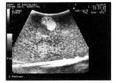
図2は本発明の実施例を示す寒天培地用Agarファントム内に硬度の異なる白玉3の腫瘤を作製し、埋没させたものに、低周波発生装置により振動を加えて、その腫瘤の画像化を行った結果を示す。
【0016】
ここで、超音波診断装置8として用いるアロカ社製prosoundSSD5500は、パワードプラー、カラードプラー、パルスドプラーを表示できる機種である。超音波探触子7は3.5MHz,5MHz,7.5MHzの超音波探触子を用いた。
【0017】
上記のような装置と発明者が自作した低周波発生装置4(パルス音源、スピーカーを有し、音量、周波数を変化させることが可能な装置、外部オシロスコープにて周波数を測定)の周波数を調整して、0から3000Hz程度の振動を加えた場合に、周波数に依存する振動を超音波グレースケール画像上にカラー表示できた。
【0018】
これらは、パワードプラーのゲインをホワイトノイズのないレベルまで上げた状態で撮影したものである(以下の図2以外の撮影でも、同様である)。
【0019】
図2(a)が振動なしの場合、図2(b)が200Hzの振動を加えた場合、図2(c)が230Hzの振動を加えた場合、図2(d)が540Hzの振動を加えた場合の画像化を示す図である。
【0020】
この図からわかるように、図2(b)に示すように、振動が中間のレベルではカラー部分が減少するが、その後増加してきており、図2(d)に示すように、540Hzで再度ピークとなったが、上記からすると周波数により振動している部分が相違している。倍周波数による共鳴が関連していると言える。
【0021】
したがって、振動の異なる部位(色のついた部分9と周囲)は、上記パワードプラー法により、明瞭に色分けされ描出される。
【0022】
なお、上記実施例では、ファントムに白玉を入れて腫瘤を模擬したが、ファントムにこんにゃく玉や寒天玉を入れて腫瘤を模擬したり、人体の部位、例えば、肝臓とその中の腫瘍であってもよい。
【0023】
図3は本発明に係るパワードプラー法による寒天ファントム内に寒天玉を入れてその寒天玉を画像化した写真を示す図であり、寒天ファントムは水に1.5%の寒天を入れ、寒天玉は水に4.0%の寒天玉を入れたものであり、図3(a)は振動を加えない場合、図3(b)は230Hzの低周波数を加えた場合である。
【0024】
これらの図から明らかなように、寒天玉の周囲が色付けされ、明らかに寒天玉を画像化することができる。
【0025】
図4は本発明に係るカラードプラー法による寒天ファントム内に寒天玉を入れた250Hzの低周波数を加えて、その寒天玉を画像化した写真を示す図であり、寒天ファントムは水に1.5%の寒天を入れ、寒天玉は水に4.0%の寒天玉を入れたものであり、寒天玉が色付けされていることがわかる。
【0026】
図5は本発明に係るパワードプラー法による人体の肝臓に低周波数を加えて画像化を試みた写真を示す図であり、右側が周波数を加えない場合、左側が200Hzの周波数を加えた場合であり、低周波の出力が弱いので、肝臓表面にまでしか達していないが、肝臓表面にカラーが付いているのがわかり、人体の臓器においても低周波数を加えることにより、その低周波数に起因した画像化が図れることが確認できた。
【0027】
このことは、硬度の異なる物質の硬度差を画像化する硬度画像(elastography)の可能性を示すものである。
【0028】
このように、低周波発生装置4から発生した低周波を試料や人体に加えて、周波数や出力強度を変化させる。
【0029】
次いで、上記したパワードプラー法、カラードプラー法のどちらの場合においても、高めの低周波数のこまかな振動をとらえることができない場合にこれを鮮明に画像化できる利点があるので、パルスドプラー法についても説明する。
【0030】
このことを図6〜図9を用いて詳細に説明する。これらの図において、寒天ファントムは水に1.5%の寒天を入れ、寒天玉は水に4.0%の寒天玉を入れたものであり、パワードプラー法により、同じ低周波数(218Hz)の振動を加えた場合でも、例えば、7.5MHzの超音波探触子では、図6に示すように、腫瘤に色が付くが、3.5MHzの超音波探触子では、図7に示すように、周りの組織に色が付く現象が見られる。このことは、この周波数(550Hz)を加えたファントム全体の振動に対して、パルスドプラー法により、図8に示すように、内部の腫瘤の速度成分の強度が、図9に示すように、腫瘤の外部の速度成分の強度に対して、高いことを示している。すなわち、7.5MHzの超音波探触子が小さな振幅でも振動速度が速い部分の信号を抽出できるのに対して、3.5MHzの超音波探触子では腫瘍の振動は検出できずに、ファントム全体の振動を拾ってしまうために、周囲の信号のみを拾い、腫瘍の周囲のみに信号を出る現象が現れる。
【0031】
なお、本発明は上記実施例に限定されるものではなく、本発明の趣旨に基づいて種々の変形が可能であり、これらを本発明の範囲から排除するものではない。
【0032】
【発明の効果】
以上、詳細に説明したように、本発明によれば、以下のような効果を奏することができる。
(1)簡単な構成で、硬度の異なる物質の硬度差の画像化を達成することができる。
(2)体内の腫瘤の硬さの違いを画像化することにより、悪性腫瘍の診断に役立てることができる。
(3)圧迫による組織の変形や偏位を画像化する従来の方法に比べ、圧迫の影響の及ばない深部の臓器の観察が可能となる。
(4)従来の医療用超音波装置と同様の画像抽出の即時性を持つことができる。更に、非磁性体を用いる必要がないため、容易に製作可能である。
【図面の簡単な説明】
【図1】 本発明の実施例を示す低周波振動併用パワードプラー装置による腫瘍硬度の画像化装置の概略構成図である。
【図2】 本発明の実施例を示す寒天培地用Agarファントム内に硬度の異なる白玉の腫瘤を作製し、埋没させたものに、低周波発生装置により振動を加えて、その腫瘤の画像化を行った結果を示す図である。
【図3】 本発明に係るパワードプラー法による寒天ファントム内に寒天玉を入れてその寒天玉を画像化した写真を示す図である。
【図4】 本発明に係るカラードプラー法による寒天ファントム内に寒天玉を入れて250Hzの低周波数を加えて、その寒天玉を画像化した写真を示す図である。
【図5】 本発明に係るパワードプラー法による人体の肝臓に低周波数を加えて画像化を試みた写真を示す図である。
【図6】 本発明に係るパワードプラー法にて寒天ファントム内に寒天玉を入れて低周波数を加えて、その寒天玉を画像化した写真を示す図(その1)である。
【図7】 本発明に係るパワードプラー法を併用した寒天ファントム内に寒天玉を入れて図6と同じ低周波数を加えて、その寒天玉を画像化した写真を示す図(その2)である。
【図8】 本発明に係るパワードプラー法にて寒天ファントム内に寒天玉を入れて低周波数を加えて、その寒天玉を画像化した写真を示す図(その3)であり、その右にパルスドプラー法により、色の付いていない腫瘍内の速度成分が示されている。
【図9】 本発明に係るパワードプラー法にて寒天ファントム内に寒天玉を入れて低周波数を加えて、その寒天玉を画像化した写真を示す図(その4)であり、その右にパルスドプラー法により、色の付いていない腫瘍外の速度成分が示されている。
【符号の説明】
1 試料
2 寒天培地用Agarファントム
3 硬度の異なる白玉
4 低周波発生装置
5 周波数・出力調整装置
6 振動子
7 超音波探触子
8 パワードプラー・カラードプラー・パルスドプラーのドプラー測定機能を有する超音波診断装置
9 色がついた部分[0001]
BACKGROUND OF THE INVENTION
The present invention relates to a medical ultrasonic diagnostic apparatus, and more particularly to an apparatus for imaging tumor hardness using a Doppler apparatus such as a power Doppler combined with a low frequency vibration or a color Doppler.
[0002]
[Prior art]
In conventional ultrasonic diagnostic techniques, blood flow is imaged by imaging the reflection time and intensity of ultrasonic waves and utilizing the Doppler phenomenon. By this method, shapes and positions of organs, tumors, blood vessels, and the like are imaged.
[0003]
By the way, a malignant tumor has a hardness of about 10 times that of a normal tissue, and it is considered useful to image the hardness difference.
[0004]
Therefore, a method of diagnosing hardness by imaging the displacement and deformation due to hardness by pressing the tissue from the external surface using an ultrasonic diagnostic apparatus, and a method of diagnosing hardness using the phase characteristics of reflected waves Is considered.
[0005]
However, in the method of compressing the tissue from the external surface, the target is limited to the tissue of the site that can be compressed from the outside. In addition, the method using the frequency and phase characteristics is complicated because it is necessary to change the circuit of the ultrasonic diagnostic apparatus itself.
[0006]
In addition, in MRI (Magnetic Resonance imaging) as an image of this hardness, a transverse wave that reaches the deep part is used, and a synchronized transverse wave similar to repeated compression is added to the trigger that receives the image signal, and distortion is applied. Since the displacement due to is imaged, it is necessary to synchronize the image signal with the compression device. Furthermore, in MRI, there are limitations such as inability to examine a patient using a pacemaker and to make a compression device with a non-magnetic material.
[0007]
A method using the same method for an ultrasonic diagnostic apparatus has also been reported. That is, it is a method using the B-mode method. Since the normal B-mode method cannot detect a transverse wave, a method of standing a glass rod in the specimen is used. The amount of deviation is measured with a trigger for each hour, the distance from the glass rod is measured, and the wave propagation is calculated. This method has a problem that a bar has to be stabbed inside the tissue (the same group as MRI tried to do the same method as MRI, but since a transverse wave cannot be detected by ultrasound, a glass rod in the tissue It seems that a transverse wave is generated by inserting and a longitudinal wave is detected).
[0008]
[Problems to be solved by the invention]
As described above, according to the conventional ultrasonic diagnostic apparatuses, all attempt to image the displacement due to the compression or the transverse wave, but it is not practical.
[0009]
In view of the above situation, the present invention pays attention to the fact that the wave propagation speed of substances with different hardness and the speed at the time of resonance vibration are different, and by adding vibration with a low frequency changed, the tissue and the tumor areshared. When the speed at the time of squealing is different, the speed between the surrounding tissue and the tumor increases. Therefore, by imaging the movement, it is possible to achieve imaging based directly on the hardness difference. It is an object to provide an ultrasonic diagnostic apparatus for medical use.
[0010]
[Means for Solving the Problems]
In order to achieve the above object, the present invention provides
[1] In a medical ultrasonic diagnostic apparatus, a low-frequency applying means for applying low-frequency vibration, a frequency / output adjusting device connected to the low-frequency applying means, and a frequency / output adjusting device connected to the frequency / output adjusting device. and the vibratoris set to a differentmaterial, using adraw puller method, by adding the low-frequency vibrations in the different materials of said hardness, provided with a device and for performing imaging of hardness difference of different substances thehardness before The frequency / output adjusting deviceisset to amplify the vibration by adding a vibration whose low frequency is changed and resonating the substances having different hardnesses at the changed low frequency, the Doppler method By using the fact that the difference in velocity between the materials with different hardness increases when the velocity at the time of resonance vibration differs between the materials with different hardness, the movement is directly imaged. Characterized in that obtaining an image based on the difference in hardness.
[0011]
[2] In a medical ultrasonic diagnostic apparatus, a low-frequency applying means that applies low-frequency vibration, a frequency / output adjusting device connected to the low-frequency applying means, and a frequency / output adjusting device connected to the frequency / output adjusting device. different, and the vibratoris set to a substance composed of tissue andtumor, using adraw puller method, by adding the low-frequency vibration to the material, equipped with a device and for performing imaging of hardness difference of thematerial, prior The frequency / output adjustment deviceisconfigured to amplify the vibration by adding a vibration whose low frequency is changed, and resonating the substance composed of the tissue and the tumor at the changed low frequency, By using the fact that thedifference in velocity between the surrounding tissue and tumor increases when the velocity at the time of resonance vibration differs between the tissue and the tumor by Doppler method, Hardness difference Characterized in that obtaining an image to.
[0012]
DETAILED DESCRIPTION OF THE INVENTION
Hereinafter, embodiments of the present invention will be described in detail.
[0013]
FIG. 1 is a schematic configuration diagram of an imaging device for tumor hardness using a power Doppler device combined with low-frequency vibration according to an embodiment of the present invention.
[0014]
In this figure, 1 is a sample (a mass simulated with a
[0015]
FIG. 2 shows an example of the present invention. An agar phantom for an agar medium, in which a mass of a
[0016]
Here, a prosss SSD5500 manufactured by Aloka Co., Ltd. used as the ultrasonic
[0017]
Adjust the frequency of the above-mentioned device and the low-frequency generator 4 (the device that has a pulse sound source and speakers and can change the volume and frequency, and measures the frequency with an external oscilloscope). When vibration of about 0 to 3000 Hz was applied, vibration depending on the frequency could be displayed in color on the ultrasonic gray scale image.
[0018]
These were taken with the gain of the power Doppler raised to a level free of white noise (the same applies to the cases other than FIG. 2 below).
[0019]
2A shows no vibration, FIG. 2B applies 200 Hz vibration, FIG. 2C applies 230 Hz vibration, and FIG. 2D applies 540 Hz vibration. FIG.
[0020]
As can be seen from this figure, as shown in FIG. 2 (b), the color portion decreases at an intermediate level of vibration, but then increases, and as shown in FIG. 2 (d), it peaks again at 540Hz. However, according to the above, the portion that vibrates with the frequency is different. It can be said that resonance by double frequency is related.
[0021]
Therefore, the parts with different vibrations (the
[0022]
In the above embodiment, a white ball was put in the phantom to simulate a tumor, but a konjac ball or agar ball was put in the phantom to simulate a tumor, or a part of the human body, for example, a liver and a tumor in it. Also good.
[0023]
Figure 3 is a view showing a photograph obtained by imaging the agar ball toenter is agar ball into the agar phantom by power Doppler method according to the present invention, the agar phantom isentering a 1.5% agar in water, agar ball is intended beeninput 4.0% agar ball in water, FIG. 3 (a) the absence of added vibration, FIG. 3 (b) is a case of adding the low frequency 230 Hz.
[0024]
As is clear from these figures, the surroundings of the agar balls are colored, and the agar balls can be clearly imaged.
[0025]
Figure 4 is the addition of low frequency 250Hz agar ball tookinto the agar phantom by color Doppler method according to the present invention, 1 the agar beads is a diagram showing a photograph of imaging, the agar phantom in water. put 5% agar, agar ball is intended beeninput 4.0% agar ball in water, it can be seen that the agar ball is colored.
[0026]
Figure 5 is a view showing a photograph of attempting an image by the addition of low frequency human liver by apowered puller method according to the present invention, if the right is not added frequencies, if left plus a frequency of 200Hz Because the low-frequency output is weak, it has reached only the liver surface, but it can be seen that the liver surface has a color, and it is caused by the low frequency added to the human organs. We were able to confirm that it was possible to achieve imaging.
[0027]
This indicates the possibility of hardness image (elastography) for imaging the hardness difference of substances having different hardness.
[0028]
In this way, the low frequency generated from the
[0029]
Then,Powered puller method described above, in the case of either the color Doppler method also, since there is an advantage that can be clearly imaged this if it is not possible to capture the minor vibrations of low frequencies higher for Parusudopura method Also explained.
[0030]
This will be described in detail with reference to FIGS. In these figures, the agar phantom was placed 1.5% agar in water, agar ball is intended beeninput 4.0% agar ball in water, by power Doppler method, the same low frequency (218Hz) For example, in the case of 7.5 MHz ultrasonic probe, the tumor is colored as shown in FIG. 6, but in the case of 3.5 MHz ultrasonic probe, it is shown in FIG. 7. As you can see, the surrounding tissue is colored. This is because, with respect to the vibration of the entire phantom to which this frequency (550 Hz) is added, the intensity of the velocity component of the internal tumor is shown in FIG. 9 by the pulse Doppler method, as shown in FIG. It shows that it is high with respect to the strength of the external velocity component. That is, while the 7.5 MHz ultrasonic probe can extract a signal of a portion where the vibration speed is high even with a small amplitude, the 3.5 MHz ultrasonic probe cannot detect tumor vibration, and the phantom. In order to pick up the entire vibration, only the surrounding signal is picked up, and a signal appears only around the tumor.
[0031]
In addition, this invention is not limited to the said Example, A various deformation | transformation is possible based on the meaning of this invention, and these are not excluded from the scope of the present invention.
[0032]
【The invention's effect】
As described above in detail, according to the present invention, the following effects can be obtained.
(1) With a simple configuration, it is possible to achieve imaging of a hardness difference between substances having different hardnesses.
(2) By imaging the difference in the hardness of the mass in the body, it can be used for diagnosis of a malignant tumor.
(3) Compared to conventional methods for imaging tissue deformation and displacement due to compression, it is possible to observe deep organs that are not affected by compression.
(4) Immediate image extraction similar to that of a conventional medical ultrasonic apparatus can be achieved. Furthermore, since it is not necessary to use a non-magnetic material, it can be easily manufactured.
[Brief description of the drawings]
FIG. 1 is a schematic configuration diagram of a tumor hardness imaging apparatus using a low-frequency vibration combined power Doppler apparatus according to an embodiment of the present invention.
FIG. 2 shows an example of the present invention, in which an agar phantom for an agar medium is made of a white ball having a different hardness and buried, and a low frequency generator is vibrated to image the tumor. It is a figure which shows the result of having performed.
3 is a diagram showing a photograph obtained by imaging the agar ball agar ballinlet is in in the agar phantom by power Doppler method according to the present invention.
[Figure 4] agar in phantom by color Doppler method according to the present invention by adding a low frequency of agar ballinlet is in 250 Hz, is a diagram illustrating the photograph obtained by imaging the agar ball.
It shows a photograph of attempted imaged low frequencies in addition to the human liver by the present invention; FIGPowered puller method according to.
[6] The agar ball into the agar phantom in powerde puller method according to the present invention by addinginput is a low frequency, a diagram (Part 1) showing a photograph obtained by imaging the agar ball.
[7] The agar ballinlet is in the power Doppler method in combination with agar phantom with the present invention by adding the same low frequency as in FIG. 6, in FIG. (Part 2) showing a photograph obtained by imaging the agar beads is there.
[8] The agar ball into the agar phantom in Power Doppler method according to the present invention by addinginput is a low frequency, a diagram (Part 3) showing a photograph obtained by imaging the agar ball, to its right The pulsed Doppler method shows the velocity component in the tumor that is not colored.
[9] Theincident is agar ball into the agar phantom in Power Doppler method according to the present invention by adding a low frequency, a diagram (part 4) showing a photograph obtained by imaging the agar ball, to its right The pulse Doppler method shows a non-colored extra-tumor velocity component.
[Explanation of symbols]
DESCRIPTION OF SYMBOLS 1
Claims (2)
Translated fromJapanese(b)該低周波付与手段に接続される周波数・出力調整装置と、
(c)該周波数・出力調整装置に接続され、硬度の異なる物質にセットされる振動子と、
(d)ドプラー法を用い、前記硬度の異なる物質に前記低周波振動を加えることにより、前記硬度の異なる物質の硬度差の画像化を行う装置とを備え、
(e)前記周波数・出力調整装置は、低周波数を変化させた振動を加えて、該変化させた低周波数で前記硬度の異なる物質を共鳴させて振動を増幅するように設定するものであり、
(f)前記ドプラー法により、前記硬度の異なる物質の間で共鳴振動時の速度が異なった場合に前記硬度の異なる物質間の速度差が大きくなることを利用して、その動きを画像化することにより、直接的に硬度差を元にした画像を得ることを特徴とする医療用超音波診断装置。(A) low frequency applying means for applying low frequency vibration;
(B) a frequency / output adjusting device connected to the low frequency applying means;
(C)a vibrator connected to the frequency / output adjusting deviceand set to a material having different hardness ;
(D ) using a Doppler method, and applying the low-frequency vibration to the material having different hardness, thereby imaging a hardness difference of the material having different hardness,
(E) before Symbol frequency and output adjustmentapparatus, in addition to vibrations of varying lowfrequency, which is configured to amplify the vibration by resonance of different substances the hardness at low frequencies is said change ,
(F) By using the Doppler method, when the speed at the time of resonance vibration is different between substances having different hardnesses, the movement difference is imaged by using the fact that the speed difference between the substances having different hardnesses becomes large. A medical ultrasonic diagnostic apparatus characterized in that an image based directly on the hardness difference is obtained.
(b)該低周波付与手段に接続される周波数・出力調整装置と、
(c)該周波数・出力調整装置に接続され、硬度の異なる、組織と腫瘍からなる物質にセットされる振動子と、
(d)ドプラー法を用い、前記物質に前記低周波振動を加えることにより、前記物質の硬度差の画像化を行う装置とを備え、
(e)前記周波数・出力調整装置は、低周波数を変化させた振動を加えて、該変化させた低周波数で前記組織と腫瘍からなる物質を共鳴させて振動を増幅するように設定するものであり、
(f)前記ドプラー法により、前記組織と腫瘍の間で共鳴振動時の速度が異なった場合に周囲組織、腫瘍間の速度差が大きくなることを利用して、その動きを画像化することにより、直接的に硬度差を元にした画像を得ることを特徴とする医療用超音波診断装置。(A) low frequency applying means for applying low frequency vibration;
(B) a frequency / output adjusting device connected to the low frequency applying means;
(C)a vibratorthat is connected to the frequency / output adjusting device andis set on a substance composed of a tissue and a tumor having different hardnesses ;
(D ) using a Doppler method, by applying the low-frequency vibration to the material, to image the hardness difference of the material,
(E) before Symbol frequency and output adjustingdevice,which in addition to vibrations of varying low frequency resonate a substance consisting of the tissue and tumor at low frequencies is said alterationis configured to amplify the vibrationAnd
(F) By imaging the movement of the Doppler method using the fact that the velocitydifference between the surrounding tissue and the tumor increases when the velocity at the time of resonance vibration differs between the tissue and the tumor. An ultrasonic diagnostic apparatus for medical use, which directly obtains an image based on a hardness difference.
Priority Applications (1)
| Application Number | Priority Date | Filing Date | Title |
|---|---|---|---|
| JP2001014955AJP4076007B2 (en) | 2001-01-23 | 2001-01-23 | Medical ultrasonic diagnostic equipment |
Applications Claiming Priority (1)
| Application Number | Priority Date | Filing Date | Title |
|---|---|---|---|
| JP2001014955AJP4076007B2 (en) | 2001-01-23 | 2001-01-23 | Medical ultrasonic diagnostic equipment |
Publications (2)
| Publication Number | Publication Date |
|---|---|
| JP2002209899A JP2002209899A (en) | 2002-07-30 |
| JP4076007B2true JP4076007B2 (en) | 2008-04-16 |
Family
ID=18881579
Family Applications (1)
| Application Number | Title | Priority Date | Filing Date |
|---|---|---|---|
| JP2001014955AExpired - Fee RelatedJP4076007B2 (en) | 2001-01-23 | 2001-01-23 | Medical ultrasonic diagnostic equipment |
Country Status (1)
| Country | Link |
|---|---|
| JP (1) | JP4076007B2 (en) |
Families Citing this family (6)
| Publication number | Priority date | Publication date | Assignee | Title |
|---|---|---|---|---|
| CA2685886C (en)* | 2007-05-16 | 2016-02-23 | Super Sonic Imagine | Method and device for measuring a mean value of visco-elasticity of a region of interest |
| JP5325847B2 (en)* | 2010-08-11 | 2013-10-23 | 毅 椎名 | Ultrasonic probe and ultrasonic diagnostic apparatus |
| JP5925438B2 (en)* | 2011-06-23 | 2016-05-25 | 株式会社東芝 | Ultrasonic diagnostic equipment |
| JP2013094223A (en)* | 2011-10-28 | 2013-05-20 | Ge Medical Systems Global Technology Co Llc | Ultrasonic diagnostic apparatus |
| JP5491671B2 (en)* | 2013-11-22 | 2014-05-14 | スーパー ソニック イマジン | Method for measuring the average value of viscoelasticity of a region of interest |
| CN114240898A (en)* | 2021-12-20 | 2022-03-25 | 山东科技大学 | System and method for generating multi-modal image description based on deep learning |
- 2001
- 2001-01-23JPJP2001014955Apatent/JP4076007B2/ennot_activeExpired - Fee Related
Also Published As
| Publication number | Publication date |
|---|---|
| JP2002209899A (en) | 2002-07-30 |
Similar Documents
| Publication | Publication Date | Title |
|---|---|---|
| Chen et al. | Shearwave dispersion ultrasound vibrometry (SDUV) for measuring tissue elasticity and viscosity | |
| Konofagou et al. | Localized harmonic motion imaging: theory, simulations and experiments | |
| Wells | Ultrasonic imaging of the human body | |
| Sarvazyan et al. | An overview of elastography-an emerging branch of medical imaging | |
| JP5530685B2 (en) | System and method for detecting areas of varying stiffness | |
| Ophir et al. | Elastography | |
| Wang et al. | Imaging feedback of histotripsy treatments using ultrasound shear wave elastography | |
| Song et al. | Coded excitation plane wave imaging for shear wave motion detection | |
| DE69738998D1 (en) | PHOTOACOUS MOM SCREENING DEVICE | |
| Wang et al. | An improved chirp coded excitation based on compression pulse weighting method in endoscopic ultrasound imaging | |
| JP2001519674A (en) | Elastography measurement and imaging method and apparatus for implementing the method | |
| JP4076007B2 (en) | Medical ultrasonic diagnostic equipment | |
| Sinkus et al. | Nonlinear viscoelastic properties of tissue assessed by ultrasound | |
| WO2019087741A1 (en) | Ultrasonic diagnostic device and method for evaluating physical properties of biological tissue | |
| Urban et al. | Harmonic motion detection in a vibrating scattering medium | |
| Hauff et al. | Ultrasound basics | |
| JP5435455B2 (en) | Focused vibration exciter | |
| Maleke et al. | Single-element focused transducer method for harmonic motion imaging | |
| Gandhi | High Intensity Focused Ultrasound (HIFU) Thermal Lesion Detection Using Local Harmonic Imaging | |
| Reilly | Ultrasound imaging technology | |
| Rivens et al. | Ultrasound monitoring techniques for focused Ultrasound therapy | |
| WO2005071437A1 (en) | Contrast dual frequency imaging | |
| Hwang et al. | Basic principles and fundamentals of EUS imaging | |
| Thorsen et al. | Basic physics of ultrasonography | |
| Kofler et al. | Optimization of medical ultrasound transducers with simulation and genetic algorithms |
Legal Events
| Date | Code | Title | Description |
|---|---|---|---|
| A977 | Report on retrieval | Free format text:JAPANESE INTERMEDIATE CODE: A971007 Effective date:20050630 | |
| A131 | Notification of reasons for refusal | Free format text:JAPANESE INTERMEDIATE CODE: A131 Effective date:20050712 | |
| A521 | Written amendment | Free format text:JAPANESE INTERMEDIATE CODE: A821 Effective date:20050824 | |
| A02 | Decision of refusal | Free format text:JAPANESE INTERMEDIATE CODE: A02 Effective date:20051018 | |
| A521 | Written amendment | Free format text:JAPANESE INTERMEDIATE CODE: A523 Effective date:20051208 | |
| A911 | Transfer of reconsideration by examiner before appeal (zenchi) | Free format text:JAPANESE INTERMEDIATE CODE: A911 Effective date:20051227 | |
| A521 | Written amendment | Free format text:JAPANESE INTERMEDIATE CODE: A821 Effective date:20051208 | |
| A912 | Removal of reconsideration by examiner before appeal (zenchi) | Free format text:JAPANESE INTERMEDIATE CODE: A912 Effective date:20060217 | |
| A521 | Written amendment | Free format text:JAPANESE INTERMEDIATE CODE: A821 Effective date:20071009 | |
| A521 | Written amendment | Free format text:JAPANESE INTERMEDIATE CODE: A523 Effective date:20071220 | |
| A61 | First payment of annual fees (during grant procedure) | Free format text:JAPANESE INTERMEDIATE CODE: A61 Effective date:20080123 | |
| R150 | Certificate of patent (=grant) or registration of utility model | Free format text:JAPANESE INTERMEDIATE CODE: R150 | |
| FPAY | Renewal fee payment (prs date is renewal date of database) | Free format text:PAYMENT UNTIL: 20110208 Year of fee payment:3 | |
| FPAY | Renewal fee payment (prs date is renewal date of database) | Free format text:PAYMENT UNTIL: 20120208 Year of fee payment:4 | |
| FPAY | Renewal fee payment (prs date is renewal date of database) | Free format text:PAYMENT UNTIL: 20130208 Year of fee payment:5 | |
| FPAY | Renewal fee payment (prs date is renewal date of database) | Free format text:PAYMENT UNTIL: 20140208 Year of fee payment:6 | |
| R250 | Receipt of annual fees | Free format text:JAPANESE INTERMEDIATE CODE: R250 | |
| LAPS | Cancellation because of no payment of annual fees | ||
| S533 | Written request for registration of change of name | Free format text:JAPANESE INTERMEDIATE CODE: R313533 | |
| R350 | Written notification of registration of transfer | Free format text:JAPANESE INTERMEDIATE CODE: R350 |