JP4072359B2 - Charged particle beam irradiation equipment - Google Patents
Charged particle beam irradiation equipmentDownload PDFInfo
- Publication number
- JP4072359B2 JP4072359B2JP2002052563AJP2002052563AJP4072359B2JP 4072359 B2JP4072359 B2JP 4072359B2JP 2002052563 AJP2002052563 AJP 2002052563AJP 2002052563 AJP2002052563 AJP 2002052563AJP 4072359 B2JP4072359 B2JP 4072359B2
- Authority
- JP
- Japan
- Prior art keywords
- charged particle
- ion beam
- particle beam
- bragg peak
- rod
- Prior art date
- Legal status (The legal status is an assumption and is not a legal conclusion. Google has not performed a legal analysis and makes no representation as to the accuracy of the status listed.)
- Expired - Lifetime
Links
Images


Classifications
- H—ELECTRICITY
- H05—ELECTRIC TECHNIQUES NOT OTHERWISE PROVIDED FOR
- H05H—PLASMA TECHNIQUE; PRODUCTION OF ACCELERATED ELECTRICALLY-CHARGED PARTICLES OR OF NEUTRONS; PRODUCTION OR ACCELERATION OF NEUTRAL MOLECULAR OR ATOMIC BEAMS
- H05H13/00—Magnetic resonance accelerators; Cyclotrons
- H05H13/04—Synchrotrons
- G—PHYSICS
- G21—NUCLEAR PHYSICS; NUCLEAR ENGINEERING
- G21K—TECHNIQUES FOR HANDLING PARTICLES OR IONISING RADIATION NOT OTHERWISE PROVIDED FOR; IRRADIATION DEVICES; GAMMA RAY OR X-RAY MICROSCOPES
- G21K5/00—Irradiation devices
- G21K5/04—Irradiation devices with beam-forming means
- A—HUMAN NECESSITIES
- A61—MEDICAL OR VETERINARY SCIENCE; HYGIENE
- A61N—ELECTROTHERAPY; MAGNETOTHERAPY; RADIATION THERAPY; ULTRASOUND THERAPY
- A61N5/00—Radiation therapy
- A61N5/10—X-ray therapy; Gamma-ray therapy; Particle-irradiation therapy
- A61N2005/1085—X-ray therapy; Gamma-ray therapy; Particle-irradiation therapy characterised by the type of particles applied to the patient
- A61N2005/1087—Ions; Protons
- A—HUMAN NECESSITIES
- A61—MEDICAL OR VETERINARY SCIENCE; HYGIENE
- A61N—ELECTROTHERAPY; MAGNETOTHERAPY; RADIATION THERAPY; ULTRASOUND THERAPY
- A61N5/00—Radiation therapy
- A61N5/10—X-ray therapy; Gamma-ray therapy; Particle-irradiation therapy
- A61N2005/1092—Details
- A61N2005/1095—Elements inserted into the radiation path within the system, e.g. filters or wedges
Landscapes
- Physics & Mathematics (AREA)
- Engineering & Computer Science (AREA)
- General Engineering & Computer Science (AREA)
- High Energy & Nuclear Physics (AREA)
- Plasma & Fusion (AREA)
- Spectroscopy & Molecular Physics (AREA)
- Radiation-Therapy Devices (AREA)
- Particle Accelerators (AREA)
Description
Translated fromJapanese【0001】
【発明の属する技術分野】
本発明は、荷電粒子ビーム照射装置に係り、特に加速器を有する荷電粒子ビーム照射装置に関する。
【0002】
【従来の技術】
加速器等の荷電粒子ビーム発生装置から出射される荷電粒子ビーム(以下、イオンビームという)は、細いビームである。照射対象部である癌腫瘍を一様に照射するためには、イオンビームは照射野形成装置によってビーム進行方向に垂直な面内で拡大(または走査)される。荷電粒子ビーム発生装置から出射されるイオンビームは一般的にエネルギーの揃ったビームである。この荷電粒子ビーム、特に陽子線及び重粒子線を照射対象部に照射した場合には、それらのエネルギーによって決まる特定の深さにピークを有する線量分布が形成される。この線量分布のピークをブラッグピークと呼ぶ。ブラッグピークの広がりは数mmと狭いので、照射野形成装置によってイオンビームを拡大して照射対象部を一様に照射する。
【0003】
また、照射対象部にイオンビームを一様に照射するためには、エネルギーの異なる複数のイオンビームを、重みを変えてたし合わせるとよい。エネルギー分布を拡大する方法としては、例えば、レビュー オブ サイエンティフィック
(Review of Scientific Instruments)Vol.64 No.8(1993年8月),2055頁〜2122頁に記載されているように、▲1▼加速器からのイオンビームのエネルギーを直接変える方法(エネルギースキャニング)、▲2▼イオンビームを、厚さに分布を有して回転している円盤状の板の一部を通過させる方法(レンジモジュレーティングプロペラ)、及び厚みに分布を有する楔形の構造物をイオンビームの通過領域に設置する方法(リッジフィルタ)が知られている。
【0004】
エネルギースキャニングを利用したエネルギー分布拡大装置は、加速器の高周波加速空胴からイオンビームに加えるエネルギーの適切な制御、及びそのエネルギーを有するイオンビームの照射量の適切な制御によって、イオンビーム照射対象部に対する全照射のエネルギー分布を所望の分布にすることができる。また、レンジモジュレーティングプロペラ(またはリッジフィルタ)を用いたエネルギー分布拡大装置は、イオンビームが通過する部分における厚みの分布を予め所望の分布に設定しておくことによって、通過したイオンビームのエネルギー分布を所望の分布にすることができる。
【0005】
更に、フィジィックス アンド メディカル バイオロジ(Physics and Medical Biology)Vol.44(1999年),2765頁〜2775頁には、照射対象部の広がりに比べて狭い範囲で、エネルギー分布をガウス分布に広げる方法が記載されている。
【0006】
特開平10−314324号公報は、状部になるほど幅が狭くなる多数の板材を重ねて構成したリッジフィルタを記載している。そのような構成によりリッジフィルタの製造が容易になる。
【0007】
【発明が解決しようとする課題】
照射対象部のビーム進行方向における厚さが厚いほど、照射対象へのイオンビームの照射に必要となるエネルギー分布は広がる。また、照射対象部のビーム進行方向における深さが浅いほど、ブラッグピークの広がりが狭くなり、イオンビームを照射対象部に一様に照射するためにエネルギー分布を密にする必要がある。いずれの場合も、前述のように、エネルギーと重みの異なるイオンビームを足し合わせる場合には、それらのイオンビームを多数発生させる必要がある。
【0008】
特開平10−314324号公報記載のリッジフィルタはイオンビームの進行方向に重ねる板材の数に相当するだけの、エネルギーが異なるイオンビーム成分を得ることができる。
【0009】
本発明の目的は、簡単な構造で、形成されるブラッグピークの深さ方向における幅を増大できる荷電粒子ビーム照射装置を提供することにある。
【0010】
【課題を解決するための手段】
上記の目的を達成する本発明の特徴は、荷電粒子ビーム走査装置で走査された荷電粒子ビームによって形成されるブラッグピークの深さ方向における幅を増大させるブラッグピーク拡大装置が、荷電粒子ビームの進行方向に順次配置されて、その進行方向と交差する方向において少なくとも1つの厚肉部をそれぞれ有する第1フィルタ部材及び第2フィルタ部材を備えており、第1フィルタ部材及び第2フィルタ部材は、お互いの厚肉部の一部分が荷電粒子ビームの進行方向において交差するように配置されていることにある。
【0011】
第1フィルタ部材及び第2フィルタ部材は、お互いの厚肉部の一部分が荷電粒子ビームの進行方向において交差するように配置されているため、簡単な構造で、複数の異なるエネルギーの荷電粒子ビーム成分を得ることができる。これらの荷電粒子ビーム成分を含む荷電粒子ビームの照射により体内に形成されるブラッグピークの深さ方向における幅をより増大できる。そのようなブラッグピークの幅の増大は、治療時間の短縮につながる。また、リッジフィルタを用いた場合には、リッジフィルタの製造が簡単になる。
【0012】
好ましくは、第1フィルタ部材と、第1フィルタ部材の厚肉部のその進行方向における厚みと異なるその厚みを有する厚肉部を備えた第2フィルタ部材とを、お互いの厚肉部の一部分が荷電粒子ビームの進行方向において交差するように配置しても、上記した簡単な構造で、形成されるブラッグピークの深さ方向における幅を増大できる。特に、第1フィルタ部材と第2フィルタ部材におけるお互いの厚肉部のその進行方向における厚みが異なっており、第1フィルタ部材及び第2フィルタ部材は、お互いの厚肉部の一部分が荷電粒子ビームの進行方向において重なるように配置されているため、荷電粒子ビームの進行方向で重なっている厚肉部の数よりも多い数の、異なるエネルギーの荷電粒子ビーム成分を得ることができる。このため、荷電粒子ビームの進行方向に少ない部材を配置する単純な構成で、より多くの、エネルギーが異なる荷電粒子ビーム成分を得ることができ、ブラッグピークの深さ方向における幅をより増大できる。
【0013】
好ましくは、荷電粒子ビーム偏向装置または荷電粒子ビーム拡大装置を用いて患部を深さ方向に複数の照射対象層に分けて照射対象層毎に荷電粒子ビームを照射する場合には、ブラッグピークの幅の増大は、照射対象層の厚みを増大でき、変更するエネルギー数を低減できる。
【0014】
好ましくは、ブラッグピーク拡大装置が、複数のフィルタ要素を、それらのフィルタ要素に設けられるお互いの棒状部の向きが異なるように重ね合わせることによって、構成され、または複数のフィルタ要素を、それらのフィルタ要素に設けられるお互いの厚肉部の向きが異なるように重ね合わせることによって、構成される。このような構成は、ブラッグピーク拡大装置の構成を単純化する。
【0015】
【発明の実施の形態】
(実施例1)
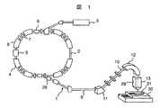
本発明の好適な一実施例である荷電粒子ビーム照射装置を、図1を用いて以下に説明する。本実施例の荷電粒子ビーム照射装置1は、荷電粒子ビーム発生装置2及び照射野形成装置13を備える。荷電粒子ビーム発生装置2は、イオン源(図示せず)、前段加速器3及びシンクロトロン4を有する。イオン源で発生したイオン(例えば、陽イオン(または炭素イオン))は前段加速器(例えば直線加速器)3で加速される。前段加速器3から出射されたイオンビームはシンクロトロン4に入射される。このイオンビームは、シンクロトロン4で、高周波加速空胴5から印加される高周波電力によってエネルギーを与えられて加速される。シンクロトロン4内を周回するイオンビームのエネルギーが設定されたエネルギーまでに高められた後、出射用の高周波印加装置6から高周波がイオンビームに印加される。安定限界内で周回しているイオンビームは、この高周波の印加によって安定限界外に移行し、出射用デフレクタ28を通ってシンクロトロン4から出射される。イオンビームの出射の際には、シンクロトロン4に設けられた四極電磁石7及び偏向電磁石8等の電磁石に導かれる電流が設定値に保持され、安定限界もほぼ一定に保持されている。高周波印加装置6への高周波電力の印加を停止することによって、シンクロトロン4からのイオンビームの出射が停止される。
【0016】
シンクロトロン4から出射されたイオンビームは、ビーム輸送系9を経て照射野形成装置13に達する。ビーム輸送系9の一部である逆U字部10及び照射野形成装置13は、回転可能なガントリー(図示せず)に設置される。逆U字部
10は偏向電磁石11,12を有する。
【0017】
照射野形成装置13は、ケーシング29内に、図2に示すように、一対の走査用電磁石14,15を有するビーム拡大装置16,ブラッグピーク拡大装置17、リッジフィルタ24及びレンジシフタ25を設置する。ビーム拡大装置16,ブラッグピーク拡大装置17,リッジフィルタ24及びレンジシフタ25は、この順序でイオンビームの進行方向において上流側から下流側に向かって配置されている。ビーム拡大装置16は、図示していないが、走査用電磁石15の下方に散乱体を備えている。散乱体は鉛またはタングステンで構成される。照射野形成装置13は、イオンビームを照射する患者毎に作成されるコリメータ26及びボーラス27を取り付けられるようになっている。レンジシフタ25はイオンビームの体内でのエネルギー分布を、体の深さ方向に移動させる機能を有する。ブラッグピーク拡大装置17はリッジフィルタ24の後段に配置してもよい。
【0018】
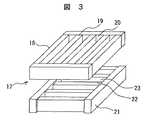
ブラッグピーク拡大装置17は、図3に模式的に示すように、一対のフィルタ要素18,21を有する。フィルタ要素18は互いの間に孔部20を形成する複数の棒状部19を備える。フィルタ要素18は複数の棒状部19の間に間隙を形成した状態でそれらの棒状部19の両端部を連結した構成を有する。換言すれば、フィルタ要素18は一枚の板に複数の細長い貫通孔(孔部20)を形成したものであるとも言える。フィルタ要素21も、フィルタ要素18と同様に、互いの間に孔部23を形成する複数の棒状部22を備え、各棒状部22の両端部を連結した構成を有する。棒状部19,22は厚肉部である。棒状部19,22の水平方向の厚みはそれぞれ1mmであり、棒状部19,22はそれぞれ1mm間隔で配置される。棒状部19,22の縦断面の形状は長方形である。フィルタ要素18はフィルタ要素21の上に設置される。フィルタ要素18とフィルタ要素21は、棒状部19と棒状部22とが互いに異なる方向(互いに90°ずれている方向)を向いて配置される。具体的には、本実施例では、フィルタ要素18とフィルタ要素21は、上から見て、棒状部19と棒状部22とが交差するように、すなわち直交するように配置される。フィルタ要素18,21の水平方向の形状は一辺が約25cmの正方形である。
【0019】
イオンビームを悪性腫瘍の患部に照射される患者31は治療台30上で照射野形成装置13の下に位置決めされる。その際には、既にその患者用のコリメータ26及びボーラス27が、レンジシフタ25の下方で照射野形成装置13内に設置されている。患者の位置決めが終了した後、設定されたエネルギーを有するイオンビームが、前述したように荷電粒子ビーム発生装置2のシンクロトロン4から出射され、逆U字部10を経て照射野形成装置13に達する。電流が、電源装置33からビーム拡大装置16の各電磁石14,15に供給される。電磁石14は水平面内のX軸方向にイオンビームの位置を移動させる。電磁石15はその水平面内でX軸と直交するY軸方向にイオンビームの位置を移動させる。本実施例は走査用電磁石14,15を用いてイオンビームをその水平面内においてある半径で旋回するように移動させる。走査用電磁石14,15は、荷電粒子ビーム走査装置として機能する。旋回されたイオンビームは、前述した散乱体の機能によって、ビーム拡大装置16へのイオンビームの入射方向に垂直な方向に拡大される。この拡大されたイオンビームがブラッグピーク拡大装置17に達する。
【0020】
ブラッグピーク拡大装置17は、通過する一部のイオンビームのエネルギーを低減させる。すなわち、フィルタ要素18の棒状部19を通過したイオンビームはエネルギーを低減する。孔部20を通過したイオンビームはエネルギーを低減しない。次のフィルタ要素21では、棒状部22を通過したイオンビームはエネルギーを減少する。孔部23を通過したイオンビームはエネルギーを低減しない。このように棒状部はイオンビームのエネルギーを減衰させる。ブラッグピーク拡大装置17を通過したイオンビームは、2つのフィルタ要素の棒状部が重なっている部分を通過した第1イオンビーム成分、どちらか一方のフィルタ要素の棒状部を通過した第2イオンビーム成分、及び2つのフィルタ要素の各孔部を通過した第3イオンビーム成分を含む。棒状部19及び22の厚みが同じであるため、ブラッグピーク拡大装置17を通過したイオンビームは、図4に示すようにエネルギーが異なる3つのイオンビーム成分に分かれる。第1イオンビーム成分は、上下方向で棒状部19,20を通過するためエネルギーの低減幅が大きく、エネルギーが最も小さくなる。各イオンビーム成分のエネルギーは、第1イオンビーム成分,第2イオンビーム成分及び第3イオンビーム成分の順に大きくなる。ブラッグピーク拡大装置17通過後のイオンビームを、直接、患者31の患部に照射した場合における患者の体内での放射線量分布は、図5のようになる。すなわち、3つのイオンビーム成分の重ね合わせにより、ブラッグピークの幅が大きくなる。このように、ブラッグピーク拡大装置は、患者31の体表面からの深さ方向においてブラッグピークの幅を増大させる機能を有する。
【0021】
ブラッグピーク拡大装置17を通過したイオンビームはリッジフィルタ24に達する。リッジフィルタ24は、図6(A)に示すように、縦断面が楔形状をした複数のフィルタ要素(楔形要素)24Aを並列に配置して構成される。フィルタ要素24Aは約1cmピッチで配置される。各フィルタ要素24Aの底面を除いた二面の表面には、図6(B)に示すように、多数の段部34が形成される。リッジフィルタ24を通過したイオンビームは、多数の段部34を形成した複数のフィルタ要素24Aによってフィルタ要素24Aの透過した部分の厚みに応じたエネルギーの異なる多数のイオンビーム成分、すなわち段部34の数だけエネルギーが異なるイオンビーム成分を含んでいる。このため、体内の深さ方向における異なる位置で段部34の数だけブラッグピークを形成することができる。
【0022】
ブラッグピーク拡大装置17が設置されない従来の照射野形成装置では、リッジフィルタの各楔形要素の一面に例えば20数段の段部が形成されている。この場合には、リッジフィルタを通過したイオンビームは、20数個のエネルギーが異なるイオンビーム成分を含んでいる。エネルギーに対するイオン数の分布は、イオンのエネルギーを決定する各段部が楔形要素に占める割合によって決まる。このため、楔形要素の縦断面の形状によって、リッジフィルタを通過したイオンビームのエネルギー分布が決まる。ブラッグピーク拡大装置17が設置されない従来の照射野形成装置において、7個の段部を一面に形成した楔形要素を有するリッジフィルタを通過したイオンビームに対するエネルギー分布を、図6に示す。イオンビームが体内において到達する深さは、イオンビームが持っているエネルギーによって決まる。エネルギーが大きいイオンビームは深い位置まで到達し、エネルギーが小さいイオンビームほど到達する位置は浅くなる。図6のようにエネルギーが異なる7個のイオンビーム成分を含むイオンビームにおいては、このイオンビームを患者に照射した場合にはエネルギーに応じて各イオンビーム成分が体内で到達する異なる7つの各位置でブラッグピークが形成される。そのようなイオンビームを照射した場合の体内の総放射線量分布は、体内の深さ方向において、それらのブラッグピークが足し合わされることによって、図8に示す線35のようになる。すなわち、放射線量が高くかつ一様になっている範囲が深さ方向に広がる。図7における各細い線で示される放射線量の分布は、楔形要素の各段部を通過したイオンビーム成分に対する放射線量分布である。放射線量が一様になっている範囲が、患部に位置するように、例えばシンクロトロン4で出射するイオンビームのエネルギーを調節する。
【0023】
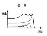
リッジフィルタの楔形要素に形成される段部の数を減らして高さ方向における段部の間隔を粗く製作した場合、リッジフィルタの製作は簡単になる。しかし、そのリッジフィルタを通過したイオンビームに含まれる、エネルギーの異なるイオンビーム成分の数が減り、各イオンビーム成分間のエネルギーの差が大きくなるため、患部内の深さ方向における放射線線量分布が図9に示すように波打つようになる。
【0024】
次に、本実施例におけるリッジフィルタ24の前段にブラッグピーク拡大装置17を設置した場合における体内の放射線分布について説明する。イオンビームは、フィルタ要素18からフィルタ要素21に向かって進行する。ブラッグピーク拡大装置17を通過したイオンビームは、前述したように、エネルギーが異なる3つのイオンビーム成分を含んでいる。このため、リッジフィルタ24を通過したイオンビームの照射によって体内に形成される各ブラッグピークの幅が広くなる。本実施例は、ブラッグピーク拡大装置17を設置しない従来の場合に比べて、リッジフィルタ24の段部34の数が2/3に低減されている。このため、リッジフィルタ24の製造が簡単になり、リッジフィルタ24の製造に要する時間も短縮できる。ブラッグピーク拡大装置17の設置により体内に形成される各ブラッグピークの幅が広くなるため、段部34の数の少ないリッジフィルタ24を用いても、図8の線35のように深さ方向における放射線量が一様になる。
【0025】
リッジフィルタ24を通過したイオンビームは、レンジシフタ25を通り、更にコリメータ26及びボーラス27を通って患部32に照射される。コリメータ26は、コリメータ26によって、治療台30上に横たわっている患者31の患部32の水平方向における形状に合わせて、拡大されたイオンビームを切取る。ボーラス27は、コリメータ26によって切取られたイオンビームのエネルギーを、患者31の体表面からの患部6の最大深さに合わせて調整する。本実施例においてイオンビームを照射した場合の体内の総放射線量は、図8の線35のようになる。
【0026】
本実施例は、ブラッグピーク拡大装置17の設置によりブラッグピークの幅を広くすることができる。このため、リッジフィルタ24によって形成される各ブラッグピークの幅が広くなり、体内に形成される総放射線量分布が一様になる。特に、本実施例は、フィルタ要素18及びフィルタ要素21を、お互いの棒状部の一部分がイオンビームの進行方向において重なるように、すなわち交差するように配置されているため、その進行方向で重なっている棒状部の数(2本)よりも多い数(3つ)の、異なるエネルギーのイオンビーム成分(図4参照)を得ることができる。これらのイオンビーム成分を含むイオンビームの患者31への照射により体内に形成されるブラッグピークの深さ方向における幅をより増大できる。本実施例は、イオンビームの進行方向に少ない棒状部を配置する単純な構成で、より多くの、エネルギーが異なるイオンビーム成分を得ることができ、ブラッグピークの深さ方向における幅をより増大できる。
【0027】
本実施例では、ブラッグピーク拡大装置17は、複数のフィルタ要素におけるお互いの棒状部、すなわち厚肉部の向きを変えるだけで、簡単にエネルギーの異なる3つののイオンビーム成分を含むイオンビームを得ることができる。お互いの厚肉部が向きを変えて重ねられた状態で両者が重なっている位置がずれても、また、お互いの厚肉部の向きが多少ずれても、3つのイオンビーム成分の各エネルギーは変わらず、かつそれらのイオンビーム成分の割合もあまり変化しない。また、以下に示すブラッグピーク拡大装置の他の実施例を用いても、上記したブラッグピーク拡大装置17の設置で得られる効果を得ることができる。
【0028】
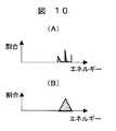
フィルタ要素18,21の棒状部19,22の縦断面の形状を、円または三角形にしてもよい。縦断面の形状が円である複数の棒状部を有する2つのフィルタ要素をそれぞれの棒状部が上から見て交差するように配置したブラッグピーク拡大装置を用いた場合には、そのブラッグピーク拡大装置を通過したイオンビームは図10(A)に示すようなエネルギーが異なるイオンビーム成分を含む。また、縦断面の形状が三角形である複数の棒状部を有する2つのフィルタ要素をそれぞれの棒状部が上から見て交差するように配置したブラッグピーク拡大装置を用いた場合には、そのブラッグピーク拡大装置を通過したイオンビームは図10(B)に示すようなエネルギーが異なるイオンビーム成分を含む。
【0029】
ブラッグピーク拡大装置の他の実施例を、図11を用いて以下に説明する。このブラッグピーク拡大装置40は、一対のフィルタ要素41,44を有する。フィルタ要素41はフィルタ要素44の上方に位置する。フィルタ要素41は棒状部42,43を交互に配置してそれらを接合している。棒状部42の縦断面形状は長方形であり、棒状部42のイオンビームの進行方向における厚みが棒状部43のその厚みよりも厚くなっている。棒状部42は原子番号が小さい元素を含む材料で構成され、棒状部43は原子番号が大きい元素を含む材料で構成される。フィルタ要素44も、フィルタ要素41と同じ構成を有する。フィルタ要素41とフィルタ要素44は、棒状部が互いに異なる方向を向くように(例えば、上から見て直交するように)配置される。イオンビームは上方よりフィルタ要素41,44を通過する。イオンビームは、2つのフィルタ要素を通過することによって、エネルギーが低減されると共に散乱される。一般に、原子番号が大きい元素を含む材料ほど、イオンビームの通過厚さが厚いほど、エネルギーの低減及び散乱の度合いが大きくなる。ブラッグピーク拡大装置40において2種類の棒状部の厚さ及び構成する元素の原子番号を適切に選択することによって、ブラッグピーク拡大装置40を通過したイオンビームのエネルギー分布を、図3に示すブラッグピーク拡大装置17と同様なエネルギー分布に形成でき、しかもイオンビームの散乱度合いを一様にすることができる。
【0030】
ブラッグピーク拡大装置の他の実施例を、図12を用いて以下に説明する。本実施例のブラッグピーク拡大装置45は上下方向に配置された一対のフィルタ要素46,51を有する。フィルタ要素46は、下側に複数の棒状部47を等間隔に並べて配置し、上側に複数の棒状部49を等間隔に配置して構成される。図示されていないが、棒状部47,49の両端部は、フィルタ要素18と同様に連結されている。棒状部49は、棒状部47の一部と重なるように水平方向にずらして配置される。棒状部47相互間に孔部48が形成され、棒状部49相互間に孔部50が形成される。孔部48と孔部50も水平方向にずれているが、それぞれの孔部は互いに連通している。棒状部47,49の縦断面形状は長方形である。フィルタ要素51も、同様に、下側に複数の棒状部52を等間隔に並べて配置し、上側に複数の棒状部54を等間隔に配置して、棒状部52,54の両端部が連結して構成される。棒状部54は、棒状部52の一部と重なるように水平方向にずらして配置される。棒状部52相互間に孔部53が形成され、棒状部54相互間に孔部55が形成される。孔部53と孔部55も水平方向にずれているが、それぞれの孔部は互いに連通している。棒状部47,49の縦断面形状は正方形である。棒状部47,49の高さ方向の厚みは棒状部52,54のその厚みの2倍ある。ブラッグピーク拡大装置45は、フィルタ要素46の棒状部47,49をフィルタ要素51の棒状部52,54と異なる方向を向くように配置し、フィルタ要素46をフィルタ要素51の上に設置している。ブラッグピーク拡大装置45を通過したイオンビームは、4つの棒状部を全て通過したイオンビーム成分、及び棒状部を通過せず孔部50、48を通過したイオンビーム成分等の図13に示すエネルギーが異なる7つのイオンビーム成分を含んでいる。7つのイオンビーム成分を含むため、ブラッグピーク拡大装置17,40よりも密なエネルギー分布を形成することができる。ブラッグピーク拡大装置45は、入射エネルギーが低く、ブラッグピークが細い場合にも適用できる。
【0031】
ブラッグピーク拡大装置の他の実施例を、図14を用いて説明する。このブラッグピーク拡大装置56はフィルタ要素57,60を有する。フィルタ要素57は、形状的にはフィルタ要素41と同じ形状を有する。フィルタ要素57は、一枚の板に複数の溝部59を形成することによって複数の凸部58を形成している。凸部58は厚肉部であり、各凸部は1つの方向に延びている。フィルタ要素60も、1つの方向に延びている複数の凸部58及び複数の溝部59を有する。ブラッグピーク拡大装置56はフィルタ要素57の凸部58とフィルタ要素60の凸部58とを異なる方向を向くように配置して、フィルタ要素57をフィルタ要素60の上に設置する。ブラッグピーク拡大装置56もブラッグピーク拡大装置17と同様にエネルギーの異なる3つのイオンビーム成分を発生させ、ブラッグピークの幅を増大させる。
【0032】
なお、図2に示す照射野形成装置13は、リッジフィルタを用いているが、リッジフィルタの替りにレンジモジュレーティングプロペラを使用してもよい。
【0033】
本実施例において、ビーム拡大装置としてビーム拡大装置16の構成のうち走査用電磁石14,15の替りに散乱体を配置したものを用いてもよい。すなわち、そのビーム拡大装置は、イオンビームの進行方向に対して二つの散乱体を直列に配置した構成を有する。二つの散乱体によって、ビーム拡大装置に入射したイオンビームはその進行方向と交差する方向に対して拡大される。
【0034】
(実施例2)
本発明の他の実施例である荷電粒子ビーム照射装置を以下に説明する。本実施例の荷電粒子ビーム照射装置は、図1に示す荷電粒子ビーム照射装置1の照射野形成装置13を図15に示す照射野形成装置13Aに替えた構成を有する。本実施例の荷電粒子照射装置の他の構成は、荷電粒子ビーム照射装置1と同じである。照射野形成装置13Aは、ケーシング内に、図15に示すように、一対の走査用電磁石14,15を有するビーム偏向装置61,ブラッグピーク拡大装置17を備える。電源装置33が走査用電磁石14,15に接続される。本実施例における走査用電磁石14,15は、として機能する。ビーム偏向装置61は、ビーム拡大装置16のようにイオンビームを、ビーム偏向装置61へのイオンビームの入射方向に対して垂直な方向に拡大することはできない。
【0035】
シンクロトロン4から出射されたイオンビームはビーム輸送系9を経て照射野形成装置13Aに達する。シンクロトロン4は、実施例1と同様に、直径が患部32に比べて小さいイオンビームを発生する。ビーム偏向装置61は、電源装置33から走査用電磁石14,15に電流を流すことによって、ビーム偏向装置13Aへのイオンビームの入射方向に対して垂直な方向に走査される。この走査によって、イオンビームを患部32に対してスキャンさせることができる。偏向されたイオンビームはブラッグピーク拡大装置17に導かれブラッグピーク拡大装置17を通過する。ブラッグピーク拡大装置17を通過したイオンビームは、実施例1と同様に、エネルギーの異なる3つのイオンビーム成分を含む。エネルギーの異なる3つのイオンビーム成分を含むイオンビームを患部32に照射することによって、ブラッグピークの幅を増加できる。シンクロトロン4によってエネルギーの異なる複数のイオンビームを発生させることによって、深さ方向において患部32を複数の領域に分割し、スキャニングによりそれぞれの分割した領域にイオンビームを照射することができる。
【0036】
すなわち、ビーム偏向装置61によるイオンビームの走査量は、予め設定された走査パターンデータに基づいて制御される。深さ方向におけるある照射対象層に対して、該当する走査パターンデータに基づいてイオンビームを走査してスキャンしながらイオンビームの照射を行う。その照射対象層への照射が終了した時点で、シンクロトロン4からのイオンビームの出射を停止し、浅い位置に存在する別の照射対象層へのイオンビームの照射を実施するための準備が行われる。すなわち、シンクロトロン4の設定パラメータが別のエネルギーのイオンビームを発生するように変更され、ビーム偏向装置61に対する走査パターンデータもその別の照射対象層に対応したパターンデータに設定される。その後、シンクロトロン4から所定エネルギーのイオンビームを出射して、そのイオンビームを照射野形成装置13Aから患部32の別の照射対象層に照射する。このような照射を繰返して患部32の全体にイオンビームを照射する。
【0037】
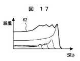
ブラッグピーク拡大装置17を用いない場合に、シンクロトロン4から図16に示すエネルギーの異なる4つのイオンビームを、図16に示す照射量で照射対象層へ順次患部32に照射した場合を考える。この場合には、患部32全体に照射された全放射線量は、図17の線62のようになる。図17の4本の細線は、各照射対象層に照射されたイオンビームによって形成されるブラッグピークを示している。線62はこれらのブラッグピークを足し合わせた総放射線量分布である。ブラッグピークの細さに対して、ブラッグピーク同士の間隔が広いため、総放射線量分布が深さ方向に不均一になる。この問題を解決するために、シンクロトロン4によりエネルギーの異なるイオンビームの発生数を増大させて照射される総放射線量分布を一様にすることが考えられる。エネルギーの異なるイオンビームの数を増加させることは、深さ方向における照射対象層の数が増加し、イオンビームの照射時間が増大する。
【0038】
これに対して、ブラッグピーク拡大装置17を設置した本実施例では、患者
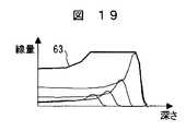
31の患部32に照射される、図16に示すエネルギーが異なる4つのイオンビームは、それぞれ、図18に示すエネルギーの異なる3つのイオンビーム成分を含む。このため、各エネルギーのイオンビームを照射することによって、それぞれのイオンビームで形成されるブラッグピークの幅が図19に細線で示すように増大する。このため、それらのブラッグピークを足し合わせた総放射線量分布は、図19の線63で示すように患部32の深さ方向において一様になる。
【0039】
本実施例は、ブラッグピーク拡大装置の設置によりブラッグピークの幅を増大できるため、シンクロトロン4でエネルギーの異なるイオンビームの数を増大させることなく、患部32の深さ方向における総放射線量分布をより一様にできる。ブラッグピークの幅を増大できるため、深さ方向に設定した照射対象層の厚みを厚くでき、患部32の照射に要する時間を短縮できる。本実施例も、フィルタ要素18,21を設置しているため実施例1で得られる作用効果を得ることができる。
【0040】
ブラッグピーク拡大装置17の替りに、前述したブラッグピーク拡大装置40,45及び56のいずれかを用いてもよい。特に、ブラッグピーク拡大装置40を用いることによって、ブラッグピーク拡大装置をイオンビームが通過する際におけるイオンビームの散乱度合いを一様に調整することができる。このため、イオンビーム走査時におけるイオンビームの直径の制御が簡単に行える。
【0041】
なお、本実施例では、深さの異なる照射対象層に対応したイオンビームエネルギーの変更を、荷電粒子ビーム発生装置のパラメータ変更により実施している。しかし、照射野形成装置13Aにレンジシフタを設け、レンジシフタの厚さを変更することによっても、イオンビームのエネルギーを変更できる。
【0042】
(実施例3)
本発明の他の実施例である荷電粒子ビーム照射装置を以下に説明する。本実施例の荷電粒子ビーム照射装置は、図1に示す荷電粒子ビーム照射装置1の照射野形成装置13を図20に示す照射野形成装置13Bに替えた構成を有する。本実施例の荷電粒子ビーム照射装置の他の構成は、荷電粒子ビーム照射装置1と同じである。照射野形成装置13Bは、ビーム拡大装置16及びブラッグピーク拡大装置64を備え、コリメータ26及びボーラス27が設置可能になっている。実施例2の照射野形成装置13Aは、患部32の深さ方向における各対象領域層内でイオンビームのスキャニングによる照射を行うことができる。本実施例に用いられる照射野形成装置13Bは、それらの対象領域層毎にビーム拡大装置16によって拡大されたイオンビームを照射する。
【0043】
ブラッグピーク拡大装置64は、図21に示すように、下側に複数の棒状部65を相互間に孔部66を形成するように配置して構成されるフィルタ要素75、上側に複数の棒状部67を相互間に孔部68を形成するように配置して構成されるフィルタ要素74を設置している。棒状部65及び67は同じ方向を向いて配置されている。棒状部67は、長手方向の全体にわたって、棒状部65の上に一部分が重なるように設置される。棒状部67の配列ピッチは棒状部65のそれと同じである。このため、孔部66の幅は孔部68の幅に等しい。図示されていないが、各棒状部65の両端部は連結され、各棒状部67の両端部も連結されている。棒状部67の高さ方向の肉厚は棒状部65のそれの2倍ある。棒状部67の一部分が前述のように棒状部65の上に一部分が重なるように設置されるため、棒状部65の上端に段部69が形成され、棒状部67の下端にも段部70が形成される。段部70は孔部66の一部分に覆い被さっている。
【0044】
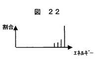
ブラッグピーク拡大装置64を通過したイオンビームは、図22に示すようにエネルギーの異なる4つのイオンビーム成分を含んでいる。棒状部65及び棒状部67の両方を通過したイオンビーム成分は最もエネルギーが小さくなる。孔部66及び68の両方を通過したイオンビーム成分は最もエネルギーが高くなる。
【0045】
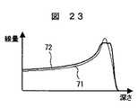
ブラッグピーク拡大装置64は、棒状部65と棒状部67との重なり部の幅によって形成されるブラッグピークの幅が異なる。すなわち、棒状部65と棒状部67との重なり部の幅が小さい場合には、図23に示す線71のように、ブラッグピークの幅は増大しない。棒状部65と棒状部67との重なり部の幅がある程度以上ある場合には、図23に示す線72のように、ブラッグピークの幅は増大する。本実施例に用いられるブラッグピーク拡大装置64は、線72に示すようなブラッグピークが形成されるように棒状部65と棒状部67とが互いに重なり合っている。
【0046】
ブラッグピーク拡大装置64を通過してエネルギーの異なる4つのイオンビーム成分を含むイオンビームは、コリメータ26及びボーラス27を通過して、患部32の最も深い位置にある照射対象層に照射される。次に、シンクロトロン4の操作によってエネルギーを低くしたイオンビームをシンクロトロン4から出射する。このイオンビームは、照射野形成装置13Bの作用によって、前回照射した照射対象層のすぐ上に位置する別の照射対象層に対して照射される。そのイオンビームもエネルギーの異なる4つのイオンビーム成分を含んでいる。このようにして、上側に位置する各照射対象層に対して、順次、イオンビームが照射される。本実施例は、深さ方向に患部32を4つの照射対象層を設定し、それぞれの照射対象層に対してブラッグピーク拡大装置64を通過したイオンビームの照射を行った。
【0047】
本実施例は、フィルタ要素74及びフィルタ要素75を、お互いの棒状部の一部分がイオンビームの進行方向において重なるように配置されているため、その進行方向で重なっている棒状部の数(2本)よりも多い数(4つ)の、異なるエネルギーのイオンビーム成分(図22参照)を得ることができる。これらのイオンビーム成分を含むイオンビームの患者31への照射により体内に形成されるブラッグピークの深さ方向における幅をより増大できる。本実施例も、イオンビームの進行方向に少ない棒状部を配置する単純な構成で、より多くの、エネルギーが異なるイオンビーム成分を得ることができ、ブラッグピークの深さ方向における幅をより増大できる。
【0048】
本実施例は、ブラッグピーク拡大装置を設置しているのでブラッグピークの幅が増大し、深さ方向における照射対象層の厚みを厚くできる。このため、患部32に対する照射に要する時間を短縮できる。しかしながら、ブラッグピーク拡大装置64は、棒状部65と棒状部67の重ね合わせ部の幅の調節が面倒である。
【0049】
以上に述べた各実施例において、シンクロトロンの替りにサイクロトロンを用いることも可能である。ビーム拡大装置16及びビーム偏向装置61は、イオンビーム走査装置である。
【0050】
【発明の効果】
本発明によれば、単純な構成で、荷電粒子ビームの照射により体内に形成されるブラッグピークの深さ方向における幅を増大できる。
【図面の簡単な説明】
【図1】本発明の好適な一実施例である荷電粒子ビーム照射装置の構成図である。
【図2】図1の照射野形成装置の詳細構成図である。
【図3】図2のブラッグピーク拡大装置の斜視図である。
【図4】ブラッグピーク拡大装置通過後のイオンビームのエネルギー分布を示す説明図である。
【図5】ブラッグピーク拡大装置通過後のイオンビームによる照射に基づいた患部内の放射線量分布を示す説明図である。
【図6】リッジフィルタの構成を示し、(A)はリッジフィルタの斜視図であり、(B)はリッジフィルタの縦断面の局部拡大図である。
【図7】リッジフィルタ通過後のイオンビームのエネルギー分布を示す説明図である。
【図8】リッジフィルタ通過後のイオンビームによる照射に基づいた患部内の放射線量分布を示す説明図である。
【図9】工作精度が悪いリッジフィルタ通過後のイオンビームによる照射に基づいた患部内の放射線量分布を示す説明図である。
【図10】棒状部の縦断面形状が異なるリップフィルタを通過した後におけるイオンビームのエネルギー分布を示し、(A)は縦断面形状が円である棒状部を有するリップフィルタに対するイオンビームのエネルギー分布を示す説明図であり、(B)は縦断面形状が三角形である棒状部を有するリップフィルタに対するイオンビームのエネルギー分布を示す説明図である。
【図11】ブラッグピーク拡大装置の他の実施例の斜視図である。
【図12】ブラッグピーク拡大装置の他の実施例の斜視図である。
【図13】図12のブラッグピーク拡大装置通過後におけるイオンビームのエネルギー分布を示す説明図である。
【図14】ブラッグピーク拡大装置の他の実施例の斜視図である。
【図15】本発明の他の実施例である荷電粒子ビーム照射装置における照射野形成装置の構成図である。
【図16】他の実施例である荷電粒子ビーム照射装置のシンクロトロンから供給されるイオンビームのエネルギーと患部への照射量割合の関係を示す説明図である。
【図17】ブラッグピーク拡大装置を設置しない場合における患部の放射線量分布を示す説明図である。
【図18】ブラッグピーク拡大装置を設置した場合における、患部に照射されるイオンビームのエネルギー分布を示す説明図である。
【図19】ブラッグピーク拡大装置を設置した場合における患部内の放射線量分布を示す説明図である。
【図20】本発明の他の実施例である荷電粒子ビーム照射装置における照射野形成装置の構成図である。
【図21】図20のブラッグピーク拡大装置の縦断面図である。
【図22】図21のブラッグピーク拡大装置を通過したイオンビームのエネルギー分布を示す説明図である。
【図23】ブラッグピーク拡大装置通過後のイオンビームを照射した際における患部内の放射線量分布を示す説明図である。
【符号の説明】
1…荷電粒子ビーム照射装置、2…荷電粒子ビーム発生装置、4…シンクロトロン、13,13A,13B…照射野形成装置、16…ビーム拡大装置、17,40,45,56,64…ブラッグピーク拡大装置、18,21,41,44,46,51…フィルタ要素、19,22,42,43,47,49,52,54,65,67…棒状部、61…ビーム偏向装置。[0001]
BACKGROUND OF THE INVENTION
The present invention relates to a charged particle beam irradiation apparatus, and more particularly to a charged particle beam irradiation apparatus having an accelerator.
[0002]
[Prior art]
A charged particle beam (hereinafter referred to as an ion beam) emitted from a charged particle beam generator such as an accelerator is a thin beam. In order to uniformly irradiate a cancer tumor as an irradiation target portion, the ion beam is expanded (or scanned) in a plane perpendicular to the beam traveling direction by an irradiation field forming device. The ion beam emitted from the charged particle beam generator is generally a beam with uniform energy. When the irradiation target part is irradiated with this charged particle beam, particularly proton beam and heavy particle beam, a dose distribution having a peak at a specific depth determined by the energy is formed. This dose distribution peak is called the Bragg peak. Since the spread of the Bragg peak is as narrow as several millimeters, the ion beam is expanded by the irradiation field forming device to uniformly irradiate the irradiation target portion.
[0003]
In addition, in order to uniformly irradiate the irradiation target portion with the ion beam, it is preferable to combine a plurality of ion beams having different energies with different weights. Examples of ways to expand energy distribution include Review of Scientific
(Review of Scientific Instruments) As described in Vol. 64 No. 8 (August 1993), pages 2055 to 2122, (1) a method of directly changing the energy of an ion beam from an accelerator (energy scanning) , (2) a method of passing an ion beam through a part of a rotating disk-shaped plate having a distribution in thickness (range modulating propeller), and a wedge-shaped structure having a distribution in thickness is ionized A method (ridge filter) that is installed in a beam passing region is known.
[0004]
An energy distribution expansion device using energy scanning is applied to an ion beam irradiation target portion by appropriately controlling the energy applied to the ion beam from the high-frequency acceleration cavity of the accelerator and appropriately controlling the irradiation amount of the ion beam having the energy. The energy distribution of all irradiations can be made a desired distribution. In addition, the energy distribution enlarging apparatus using the range modulating propeller (or ridge filter) sets the distribution of the thickness in the portion through which the ion beam passes to a desired distribution in advance, so that the energy distribution of the ion beam that has passed therethrough is set. Can have a desired distribution.
[0005]
Furthermore, in Physics and Medical Biology Vol. 44 (1999), pages 2765 to 2775, there is a method for expanding the energy distribution to a Gaussian distribution in a narrow range compared to the extent of the irradiation target part. Are listed.
[0006]
Japanese Patent Application Laid-Open No. 10-314324 describes a ridge filter formed by stacking a large number of plate members whose widths become narrower as they become a shape portion. Such a configuration facilitates the manufacture of the ridge filter.
[0007]
[Problems to be solved by the invention]
The greater the thickness of the irradiation target portion in the beam traveling direction, the wider the energy distribution required for irradiation of the ion beam to the irradiation target. In addition, as the depth of the irradiation target portion in the beam traveling direction is shallower, the spread of the Bragg peak becomes narrower, and it is necessary to make the energy distribution dense in order to uniformly irradiate the irradiation target portion with the ion beam. In any case, as described above, when ion beams having different energies and weights are added, it is necessary to generate many ion beams.
[0008]
The ridge filter described in Japanese Patent Application Laid-Open No. 10-314324 can obtain ion beam components having different energies corresponding to the number of plate materials stacked in the traveling direction of the ion beam.
[0009]
An object of the present invention is to provide a charged particle beam irradiation apparatus capable of increasing the width of the formed Bragg peak in the depth direction with a simple structure.
[0010]
[Means for Solving the Problems]
A feature of the present invention that achieves the above object is that the Bragg peak expanding device for increasing the width in the depth direction of the Bragg peak formed by the charged particle beam scanned by the charged particle beam scanning device is the progression of the charged particle beam. The first filter member and the second filter member are sequentially arranged in the direction and each have at least one thick portion in a direction crossing the traveling direction. In other words, a part of the thick-walled portion is arranged so as to intersect in the traveling direction of the charged particle beam.
[0011]
Since the first filter member and the second filter member are arranged so that a part of each thick part intersects in the traveling direction of the charged particle beam, a plurality of charged particle beam components having different energy with a simple structure. Can be obtained. The width in the depth direction of the Bragg peak formed in the body by irradiation with the charged particle beam containing these charged particle beam components can be further increased. Such an increase in the width of the Bragg peak leads to a reduction in treatment time. Further, when the ridge filter is used, the ridge filter can be easily manufactured.
[0012]
Preferably, A first filter member and a second filter member having a thick portion having a thickness different from the thickness of the thick portion of the first filter member in the traveling direction thereof, a portion of each thick portion being a charged particle beam Even if they are arranged so as to cross each other in the traveling direction, the width in the depth direction of the formed Bragg peak can be increased with the above-described simple structure. In particular, the thicknesses of the thick portions of the first filter member and the second filter member in the traveling direction are different from each other, and the first filter member and the second filter member have a portion of the thick portions of the charged particle beam. Therefore, a larger number of charged particle beam components having different energies than the number of thick portions overlapping in the traveling direction of the charged particle beam can be obtained. For this reason,load With a simple configuration in which few members are arranged in the traveling direction of the electron particle beam, more charged particle beam components having different energies can be obtained, and the width of the Bragg peak in the depth direction can be further increased.
[0013]
Preferably, when a charged particle beam deflecting device or a charged particle beam expanding device is used to divide the affected part into a plurality of irradiation target layers in the depth direction and the charged particle beam is irradiated for each irradiation target layer, the width of the Bragg peak The increase in the thickness can increase the thickness of the irradiation target layer and can reduce the number of energy changes.
[0014]
Preferably, the Bragg peak enlarging device is configured by superimposing the plurality of filter elements such that the directions of the rods provided in the filter elements are different from each other, or the plurality of filter elements are combined with the filter elements. It is configured by superimposing such that the directions of the thick portions provided in the element are different. Such a configuration simplifies the configuration of the Bragg peak enlarging device.
[0015]
DETAILED DESCRIPTION OF THE INVENTION
Example 1
A charged particle beam irradiation apparatus according to a preferred embodiment of the present invention will be described below with reference to FIG. The charged particle beam irradiation apparatus 1 of this embodiment includes a charged particle beam generation apparatus 2 and an irradiation
[0016]
The ion beam emitted from the synchrotron 4 reaches the irradiation
10 has
[0017]
As shown in FIG. 2, the irradiation
[0018]
The Bragg
[0019]
A patient 31 to be irradiated with an ion beam to an affected area of a malignant tumor is positioned below the irradiation
[0020]
The Bragg
[0021]
The ion beam that has passed through the Bragg
[0022]
In the conventional irradiation field forming apparatus in which the Bragg
[0023]
When the number of step portions formed on the wedge-shaped element of the ridge filter is reduced and the step interval in the height direction is made rough, the manufacture of the ridge filter becomes simple. However, the number of ion beam components with different energies included in the ion beam that has passed through the ridge filter is reduced, and the energy difference between the ion beam components is increased, so that the radiation dose distribution in the depth direction within the affected area is increased. As shown in FIG.
[0024]
Next, the radiation distribution in the body when the Bragg
[0025]
The ion beam that has passed through the
[0026]
In this embodiment, the width of the Bragg peak can be widened by installing the Bragg
[0027]
In the present embodiment, the Bragg
[0028]
The shape of the longitudinal section of the rod-
[0029]
Another embodiment of the Bragg peak enlarging apparatus will be described below with reference to FIG. The Bragg
[0030]
Another embodiment of the Bragg peak enlarging apparatus will be described below with reference to FIG. The Bragg
[0031]
Another embodiment of the Bragg peak enlarging apparatus will be described with reference to FIG. The Bragg
[0032]
The irradiation
[0033]
In the present embodiment, a configuration in which a scatterer is arranged instead of the
[0034]
(Example 2)
A charged particle beam irradiation apparatus according to another embodiment of the present invention will be described below. The charged particle beam irradiation apparatus of the present embodiment has a configuration in which the irradiation
[0035]
The ion beam emitted from the synchrotron 4 reaches the irradiation
[0036]
That is, the scanning amount of the ion beam by the beam deflecting device 61 is controlled based on preset scanning pattern data. An irradiation target layer in the depth direction is irradiated with an ion beam while being scanned by scanning the ion beam based on the corresponding scanning pattern data. When the irradiation of the irradiation target layer is completed, the extraction of the ion beam from the synchrotron 4 is stopped, and preparations for performing the irradiation of the ion beam to another irradiation target layer existing at a shallow position are performed. Is called. That is, the setting parameter of the synchrotron 4 is changed so as to generate an ion beam having a different energy, and the scanning pattern data for the beam deflecting device 61 is also set to the pattern data corresponding to the other irradiation target layer. Thereafter, an ion beam having a predetermined energy is emitted from the synchrotron 4, and the ion beam is irradiated onto another irradiation target layer of the affected
[0037]
When the Bragg
[0038]
On the other hand, in this embodiment in which the Bragg
The four ion beams with different energies shown in FIG. 16 irradiated to the affected
[0039]
In this embodiment, since the width of the Bragg peak can be increased by installing the Bragg peak expanding device, the total radiation dose distribution in the depth direction of the affected
[0040]
Instead of the Bragg
[0041]
In the present embodiment, the ion beam energy corresponding to the irradiation target layer having a different depth is changed by changing the parameters of the charged particle beam generator. However, the energy of the ion beam can also be changed by providing a range shifter in the irradiation
[0042]
(Example 3)
A charged particle beam irradiation apparatus according to another embodiment of the present invention will be described below. The charged particle beam irradiation apparatus of the present embodiment has a configuration in which the irradiation
[0043]
As shown in FIG. 21, the Bragg
[0044]
The ion beam that has passed through the Bragg
[0045]
The width of the Bragg peak formed in the Bragg
[0046]
The ion beam including four ion beam components having different energies passing through the Bragg
[0047]
In this embodiment, the
[0048]
In this embodiment, since the Bragg peak enlarging device is installed, the width of the Bragg peak is increased, and the thickness of the irradiation target layer in the depth direction can be increased. For this reason, the time required for irradiation with respect to the
[0049]
In each of the embodiments described above, a cyclotron can be used instead of the synchrotron. The
[0050]
【The invention's effect】
According to the present invention, the width in the depth direction of the Bragg peak formed in the body by irradiation with a charged particle beam can be increased with a simple configuration.
[Brief description of the drawings]
FIG. 1 is a configuration diagram of a charged particle beam irradiation apparatus according to a preferred embodiment of the present invention.
2 is a detailed configuration diagram of the irradiation field forming apparatus of FIG. 1;
FIG. 3 is a perspective view of the Bragg peak enlarging device in FIG. 2;
FIG. 4 is an explanatory diagram showing an energy distribution of an ion beam after passing through a Bragg peak enlarging device.
FIG. 5 is an explanatory diagram showing a radiation dose distribution in an affected area based on irradiation with an ion beam after passing through a Bragg peak enlarging apparatus.
6A and 6B show a configuration of a ridge filter, wherein FIG. 6A is a perspective view of the ridge filter, and FIG. 6B is a local enlarged view of a longitudinal section of the ridge filter.
FIG. 7 is an explanatory diagram showing an energy distribution of an ion beam after passing through a ridge filter.
FIG. 8 is an explanatory diagram showing a radiation dose distribution in an affected area based on irradiation with an ion beam after passing through a ridge filter.
FIG. 9 is an explanatory diagram showing a radiation dose distribution in an affected area based on irradiation with an ion beam after passing through a ridge filter with poor machining accuracy.
FIG. 10 shows the energy distribution of an ion beam after passing through a lip filter having a different vertical cross-sectional shape of the rod-shaped portion. FIG. 10A shows the energy distribution of the ion beam for a lip filter having a rod-shaped portion having a circular vertical cross-sectional shape. (B) is explanatory drawing which shows energy distribution of the ion beam with respect to the lip filter which has a rod-shaped part whose longitudinal cross-sectional shape is a triangle.
FIG. 11 is a perspective view of another embodiment of the Bragg peak enlarging apparatus.
FIG. 12 is a perspective view of another embodiment of the Bragg peak enlarging device.
13 is an explanatory diagram showing an energy distribution of an ion beam after passing through the Bragg peak enlarging device in FIG. 12. FIG.
FIG. 14 is a perspective view of another embodiment of the Bragg peak enlarging device.
FIG. 15 is a configuration diagram of an irradiation field forming apparatus in a charged particle beam irradiation apparatus according to another embodiment of the present invention.
FIG. 16 is an explanatory diagram showing the relationship between the energy of an ion beam supplied from a synchrotron of a charged particle beam irradiation apparatus according to another embodiment and the irradiation dose ratio to the affected area.
FIG. 17 is an explanatory diagram showing a radiation dose distribution of an affected area when no Bragg peak enlarging device is installed.
FIG. 18 is an explanatory diagram showing an energy distribution of an ion beam irradiated to an affected area when a Bragg peak enlarging device is installed.
FIG. 19 is an explanatory diagram showing a radiation dose distribution in an affected area when a Bragg peak enlarging device is installed.
FIG. 20 is a configuration diagram of an irradiation field forming apparatus in a charged particle beam irradiation apparatus according to another embodiment of the present invention.
21 is a longitudinal sectional view of the Bragg peak enlarging device in FIG. 20;
22 is an explanatory diagram showing an energy distribution of an ion beam that has passed through the Bragg peak enlarging device of FIG. 21. FIG.
FIG. 23 is an explanatory diagram showing a radiation dose distribution in an affected area when an ion beam is irradiated after passing through the Bragg peak enlarging apparatus.
[Explanation of symbols]
DESCRIPTION OF SYMBOLS 1 ... Charged particle beam irradiation apparatus, 2 ... Charged particle beam generator, 4 ... Synchrotron, 13, 13A, 13B ... Irradiation field forming apparatus, 16 ... Beam expansion apparatus, 17, 40, 45, 56, 64 ... Bragg peak Enlarging device, 18, 21, 41, 44, 46, 51... Filter element, 19, 22, 42, 43, 47, 49, 52, 54, 65, 67.
Claims (5)
Translated fromJapanese前記照射装置が、前記荷電粒子ビームを走査する荷電粒子ビーム走査装置と、前記荷電粒子ビーム走査装置で走査された前記荷電粒子ビームによって形成されるブラッグピークの深さ方向における幅を増大させるブラッグピーク拡大装置とを有し、
前記ブラッグピーク拡大装置が、前記荷電粒子ビームの進行方向に順次配置されて、その進行方向と交差する方向において一方向に延びる少なくとも1つの厚肉部をそれぞれ有する第1フィルタ部材及び第2フィルタ部材を備えており、
前記第1フィルタ部材及び前記第2フィルタ部材は、互いに前記厚肉部の延びている方向が異なるように配置されており、
前記第1フィルタ部材及び前記第2フィルタ部材は、それぞれ、前記厚肉部の間に位置した、前記厚肉部よりも肉厚が薄い薄肉部を有していることを特徴とする荷電粒子ビーム照射装置。A charged particle beam generator including an accelerator, and an irradiation device that irradiates the irradiation target portion with the charged particle beam from the charged particle beam generator;
The irradiation device increases the width in the depth direction of the Bragg peak formed by the charged particle beam scanning device that scans the charged particle beam and the charged particle beam scanned by the charged particle beam scanning device. A magnifying device,
It said Bragg peak spreading device, wherein are sequentially disposed in the traveling direction of the charged particle beam, the first filter member and the second filter member having at least one thick portion respectively extending in one direction in a direction crossingthe traveling direction With
The first filter member and the second filter member are disposed so that the extending direction of the thick portion is different from each other,
The charged particle beam,wherein the first filter member and the second filter member each have a thin portion that is located between the thick portions and is thinner than the thick portion. Irradiation device.
前記照射装置が、前記荷電粒子ビームを走査する荷電粒子ビーム走査装置と、前記荷電粒子ビーム走査装置で走査された前記荷電粒子ビームによって形成されるブラッグピークの深さ方向における幅を増大させるブラッグピーク拡大装置とを有し、
前記ブラッグピーク拡大装置が、前記荷電粒子ビームの進行方向に順次配置されて、その進行方向と交差する方向において一方向に延びる少なくとも1つの厚肉部をそれぞれ有する第1フィルタ部材及び第2フィルタ部材を備えており、
前記第1フィルタ部材及び前記第2フィルタ部材は、互いに前記厚肉部の延びている方向が異なるように配置されており、
前記第1フィルタ部材及び前記第2フィルタ部材は前記厚肉部である複数の棒状部を有し、前記第1フィルタ部材及び前記第2フィルタ部材においてそれぞれの前記複数の棒状部が間隔をおいて配置されていることを特徴とする荷電粒子ビーム照射装置。A charged particle beam generator including an accelerator, and an irradiation device that irradiates the irradiation target portion with the charged particle beam from the charged particle beam generator;
The irradiation device increases the width in the depth direction of the Bragg peak formed by the charged particle beam scanning device that scans the charged particle beam and the charged particle beam scanned by the charged particle beam scanning device. A magnifying device,
A first filter member and a second filter member, wherein the Bragg peak enlarging device has at least one thick portion that is sequentially arranged in the traveling direction of the charged particle beam and extends in one direction in a direction crossing the traveling direction. With
The first filter member and the second filter member are disposed so that the extending direction of the thick portion is different from each other,
The first filter member and the second filter member have a plurality of rod-shaped portions that are the thick portions, and the plurality of rod-shaped portions in the first filter member and the second filter member are spaced apart from each other.A charged particle beam irradiation apparatuscharacterized by being arranged.
Priority Applications (2)
| Application Number | Priority Date | Filing Date | Title |
|---|---|---|---|
| JP2002052563AJP4072359B2 (en) | 2002-02-28 | 2002-02-28 | Charged particle beam irradiation equipment |
| US10/253,488US6617598B1 (en) | 2002-02-28 | 2002-09-25 | Charged particle beam irradiation apparatus |
Applications Claiming Priority (1)
| Application Number | Priority Date | Filing Date | Title |
|---|---|---|---|
| JP2002052563AJP4072359B2 (en) | 2002-02-28 | 2002-02-28 | Charged particle beam irradiation equipment |
Publications (2)
| Publication Number | Publication Date |
|---|---|
| JP2003255093A JP2003255093A (en) | 2003-09-10 |
| JP4072359B2true JP4072359B2 (en) | 2008-04-09 |
Family
ID=27750889
Family Applications (1)
| Application Number | Title | Priority Date | Filing Date |
|---|---|---|---|
| JP2002052563AExpired - LifetimeJP4072359B2 (en) | 2002-02-28 | 2002-02-28 | Charged particle beam irradiation equipment |
Country Status (2)
| Country | Link |
|---|---|
| US (1) | US6617598B1 (en) |
| JP (1) | JP4072359B2 (en) |
Families Citing this family (150)
| Publication number | Priority date | Publication date | Assignee | Title |
|---|---|---|---|---|
| US6777700B2 (en)* | 2002-06-12 | 2004-08-17 | Hitachi, Ltd. | Particle beam irradiation system and method of adjusting irradiation apparatus |
| DE10323654A1 (en)* | 2003-05-26 | 2004-12-30 | GSI Gesellschaft für Schwerionenforschung mbH | Energy filtering device |
| US7317192B2 (en)* | 2003-06-02 | 2008-01-08 | Fox Chase Cancer Center | High energy polyenergetic ion selection systems, ion beam therapy systems, and ion beam treatment centers |
| JP3685194B2 (en)* | 2003-09-10 | 2005-08-17 | 株式会社日立製作所 | Particle beam therapy device, range modulation rotation device, and method of attaching range modulation rotation device |
| JP3643371B1 (en)* | 2003-12-10 | 2005-04-27 | 株式会社日立製作所 | Method of adjusting particle beam irradiation apparatus and irradiation field forming apparatus |
| EP1790203B1 (en) | 2004-07-21 | 2015-12-30 | Mevion Medical Systems, Inc. | A programmable radio frequency waveform generator for a synchrocyclotron |
| DE112005002154T5 (en)* | 2005-02-04 | 2008-04-10 | Mitsubishi Denki K.K. | Particle beam irradiation method and particle beam irradiation apparatus for such a method |
| JP2006280457A (en)* | 2005-03-31 | 2006-10-19 | Hitachi Ltd | Charged particle beam extraction apparatus and charged particle beam extraction method |
| EP2389977A3 (en) | 2005-11-18 | 2012-01-25 | Still River Systems, Inc. | Charged particle radiation therapy |
| US8076657B2 (en) | 2007-02-27 | 2011-12-13 | Wisconsin Alumni Research Foundation | Ion radiation therapy system having magnetic fan beam former |
| US8269196B2 (en)* | 2007-02-27 | 2012-09-18 | Wisconsin Alumni Research Foundation | Heavy ion radiation therapy system with stair-step modulation |
| WO2008106492A1 (en)* | 2007-02-27 | 2008-09-04 | Wisconsin Alumni Research Foundation | Scanning aperture ion beam modulator |
| US7714309B2 (en)* | 2007-02-27 | 2010-05-11 | Wisconsin Alumni Research Foundation | Phantom for ion range detection |
| US8093568B2 (en)* | 2007-02-27 | 2012-01-10 | Wisconsin Alumni Research Foundation | Ion radiation therapy system with rocking gantry motion |
| US7977657B2 (en)* | 2007-02-27 | 2011-07-12 | Wisconsin Alumni Research Foundation | Ion radiation therapy system with distal gradient tracking |
| WO2008106496A1 (en)* | 2007-02-27 | 2008-09-04 | Wisconsin Alumni Research Foundation | Ion radiation therapy system with variable beam resolution |
| US8129701B2 (en) | 2007-02-27 | 2012-03-06 | Al-Sadah Jihad H | Areal modulator for intensity modulated radiation therapy |
| WO2008106522A2 (en)* | 2007-02-27 | 2008-09-04 | Wisconsin Alumni Research Foundation | System and method for optimization of a radiation therapy plan in the presence of motion |
| US9006677B2 (en)* | 2007-02-27 | 2015-04-14 | Wisconsin Alumni Research Foundation | Fan beam modulator for ion beams providing continuous intensity modulation |
| US8933650B2 (en) | 2007-11-30 | 2015-01-13 | Mevion Medical Systems, Inc. | Matching a resonant frequency of a resonant cavity to a frequency of an input voltage |
| US8581523B2 (en) | 2007-11-30 | 2013-11-12 | Mevion Medical Systems, Inc. | Interrupted particle source |
| EP2277590B1 (en)* | 2008-05-12 | 2015-03-11 | Mitsubishi Electric Corporation | Charged particle beam irradiation device |
| US8188688B2 (en) | 2008-05-22 | 2012-05-29 | Vladimir Balakin | Magnetic field control method and apparatus used in conjunction with a charged particle cancer therapy system |
| US9737272B2 (en) | 2008-05-22 | 2017-08-22 | W. Davis Lee | Charged particle cancer therapy beam state determination apparatus and method of use thereof |
| US9682254B2 (en) | 2008-05-22 | 2017-06-20 | Vladimir Balakin | Cancer surface searing apparatus and method of use thereof |
| US9616252B2 (en) | 2008-05-22 | 2017-04-11 | Vladimir Balakin | Multi-field cancer therapy apparatus and method of use thereof |
| US8373143B2 (en) | 2008-05-22 | 2013-02-12 | Vladimir Balakin | Patient immobilization and repositioning method and apparatus used in conjunction with charged particle cancer therapy |
| US8089054B2 (en) | 2008-05-22 | 2012-01-03 | Vladimir Balakin | Charged particle beam acceleration and extraction method and apparatus used in conjunction with a charged particle cancer therapy system |
| US9155911B1 (en) | 2008-05-22 | 2015-10-13 | Vladimir Balakin | Ion source method and apparatus used in conjunction with a charged particle cancer therapy system |
| WO2009142546A2 (en) | 2008-05-22 | 2009-11-26 | Vladimir Yegorovich Balakin | Multi-field charged particle cancer therapy method and apparatus |
| US9782140B2 (en) | 2008-05-22 | 2017-10-10 | Susan L. Michaud | Hybrid charged particle / X-ray-imaging / treatment apparatus and method of use thereof |
| US9095040B2 (en) | 2008-05-22 | 2015-07-28 | Vladimir Balakin | Charged particle beam acceleration and extraction method and apparatus used in conjunction with a charged particle cancer therapy system |
| US8688197B2 (en) | 2008-05-22 | 2014-04-01 | Vladimir Yegorovich Balakin | Charged particle cancer therapy patient positioning method and apparatus |
| US8718231B2 (en) | 2008-05-22 | 2014-05-06 | Vladimir Balakin | X-ray tomography method and apparatus used in conjunction with a charged particle cancer therapy system |
| US9056199B2 (en) | 2008-05-22 | 2015-06-16 | Vladimir Balakin | Charged particle treatment, rapid patient positioning apparatus and method of use thereof |
| US8624528B2 (en) | 2008-05-22 | 2014-01-07 | Vladimir Balakin | Method and apparatus coordinating synchrotron acceleration periods with patient respiration periods |
| US8093564B2 (en)* | 2008-05-22 | 2012-01-10 | Vladimir Balakin | Ion beam focusing lens method and apparatus used in conjunction with a charged particle cancer therapy system |
| US9168392B1 (en) | 2008-05-22 | 2015-10-27 | Vladimir Balakin | Charged particle cancer therapy system X-ray apparatus and method of use thereof |
| US8178859B2 (en) | 2008-05-22 | 2012-05-15 | Vladimir Balakin | Proton beam positioning verification method and apparatus used in conjunction with a charged particle cancer therapy system |
| US8710462B2 (en) | 2008-05-22 | 2014-04-29 | Vladimir Balakin | Charged particle cancer therapy beam path control method and apparatus |
| US9910166B2 (en) | 2008-05-22 | 2018-03-06 | Stephen L. Spotts | Redundant charged particle state determination apparatus and method of use thereof |
| US9855444B2 (en) | 2008-05-22 | 2018-01-02 | Scott Penfold | X-ray detector for proton transit detection apparatus and method of use thereof |
| US8569717B2 (en) | 2008-05-22 | 2013-10-29 | Vladimir Balakin | Intensity modulated three-dimensional radiation scanning method and apparatus |
| US8368038B2 (en) | 2008-05-22 | 2013-02-05 | Vladimir Balakin | Method and apparatus for intensity control of a charged particle beam extracted from a synchrotron |
| US10548551B2 (en) | 2008-05-22 | 2020-02-04 | W. Davis Lee | Depth resolved scintillation detector array imaging apparatus and method of use thereof |
| US8642978B2 (en) | 2008-05-22 | 2014-02-04 | Vladimir Balakin | Charged particle cancer therapy dose distribution method and apparatus |
| JP2011523169A (en) | 2008-05-22 | 2011-08-04 | エゴロヴィチ バラキン、ウラジミール | Charged particle beam extraction method and apparatus for use with a charged particle cancer treatment system |
| US10092776B2 (en) | 2008-05-22 | 2018-10-09 | Susan L. Michaud | Integrated translation/rotation charged particle imaging/treatment apparatus and method of use thereof |
| EP2283711B1 (en) | 2008-05-22 | 2018-07-11 | Vladimir Yegorovich Balakin | Charged particle beam acceleration apparatus as part of a charged particle cancer therapy system |
| US9579525B2 (en) | 2008-05-22 | 2017-02-28 | Vladimir Balakin | Multi-axis charged particle cancer therapy method and apparatus |
| US8969834B2 (en) | 2008-05-22 | 2015-03-03 | Vladimir Balakin | Charged particle therapy patient constraint apparatus and method of use thereof |
| US8374314B2 (en) | 2008-05-22 | 2013-02-12 | Vladimir Balakin | Synchronized X-ray / breathing method and apparatus used in conjunction with a charged particle cancer therapy system |
| US9981147B2 (en) | 2008-05-22 | 2018-05-29 | W. Davis Lee | Ion beam extraction apparatus and method of use thereof |
| US7940894B2 (en) | 2008-05-22 | 2011-05-10 | Vladimir Balakin | Elongated lifetime X-ray method and apparatus used in conjunction with a charged particle cancer therapy system |
| US8598543B2 (en) | 2008-05-22 | 2013-12-03 | Vladimir Balakin | Multi-axis/multi-field charged particle cancer therapy method and apparatus |
| US8045679B2 (en) | 2008-05-22 | 2011-10-25 | Vladimir Balakin | Charged particle cancer therapy X-ray method and apparatus |
| US8907309B2 (en) | 2009-04-17 | 2014-12-09 | Stephen L. Spotts | Treatment delivery control system and method of operation thereof |
| US8975600B2 (en) | 2008-05-22 | 2015-03-10 | Vladimir Balakin | Treatment delivery control system and method of operation thereof |
| US9937362B2 (en) | 2008-05-22 | 2018-04-10 | W. Davis Lee | Dynamic energy control of a charged particle imaging/treatment apparatus and method of use thereof |
| US7943913B2 (en) | 2008-05-22 | 2011-05-17 | Vladimir Balakin | Negative ion source method and apparatus used in conjunction with a charged particle cancer therapy system |
| WO2009142549A2 (en) | 2008-05-22 | 2009-11-26 | Vladimir Yegorovich Balakin | Multi-axis charged particle cancer therapy method and apparatus |
| US8637833B2 (en) | 2008-05-22 | 2014-01-28 | Vladimir Balakin | Synchrotron power supply apparatus and method of use thereof |
| US8144832B2 (en) | 2008-05-22 | 2012-03-27 | Vladimir Balakin | X-ray tomography method and apparatus used in conjunction with a charged particle cancer therapy system |
| US9737734B2 (en) | 2008-05-22 | 2017-08-22 | Susan L. Michaud | Charged particle translation slide control apparatus and method of use thereof |
| US8129699B2 (en) | 2008-05-22 | 2012-03-06 | Vladimir Balakin | Multi-field charged particle cancer therapy method and apparatus coordinated with patient respiration |
| US8399866B2 (en) | 2008-05-22 | 2013-03-19 | Vladimir Balakin | Charged particle extraction apparatus and method of use thereof |
| US8378311B2 (en) | 2008-05-22 | 2013-02-19 | Vladimir Balakin | Synchrotron power cycling apparatus and method of use thereof |
| US9177751B2 (en) | 2008-05-22 | 2015-11-03 | Vladimir Balakin | Carbon ion beam injector apparatus and method of use thereof |
| US8378321B2 (en) | 2008-05-22 | 2013-02-19 | Vladimir Balakin | Charged particle cancer therapy and patient positioning method and apparatus |
| US10070831B2 (en) | 2008-05-22 | 2018-09-11 | James P. Bennett | Integrated cancer therapy—imaging apparatus and method of use thereof |
| US10029122B2 (en) | 2008-05-22 | 2018-07-24 | Susan L. Michaud | Charged particle—patient motion control system apparatus and method of use thereof |
| US9737733B2 (en) | 2008-05-22 | 2017-08-22 | W. Davis Lee | Charged particle state determination apparatus and method of use thereof |
| US8896239B2 (en) | 2008-05-22 | 2014-11-25 | Vladimir Yegorovich Balakin | Charged particle beam injection method and apparatus used in conjunction with a charged particle cancer therapy system |
| US8129694B2 (en) | 2008-05-22 | 2012-03-06 | Vladimir Balakin | Negative ion beam source vacuum method and apparatus used in conjunction with a charged particle cancer therapy system |
| US8519365B2 (en) | 2008-05-22 | 2013-08-27 | Vladimir Balakin | Charged particle cancer therapy imaging method and apparatus |
| WO2009142548A2 (en) | 2008-05-22 | 2009-11-26 | Vladimir Yegorovich Balakin | X-ray method and apparatus used in conjunction with a charged particle cancer therapy system |
| US9044600B2 (en) | 2008-05-22 | 2015-06-02 | Vladimir Balakin | Proton tomography apparatus and method of operation therefor |
| US10143854B2 (en) | 2008-05-22 | 2018-12-04 | Susan L. Michaud | Dual rotation charged particle imaging / treatment apparatus and method of use thereof |
| US8198607B2 (en) | 2008-05-22 | 2012-06-12 | Vladimir Balakin | Tandem accelerator method and apparatus used in conjunction with a charged particle cancer therapy system |
| US10684380B2 (en) | 2008-05-22 | 2020-06-16 | W. Davis Lee | Multiple scintillation detector array imaging apparatus and method of use thereof |
| US7953205B2 (en) | 2008-05-22 | 2011-05-31 | Vladimir Balakin | Synchronized X-ray / breathing method and apparatus used in conjunction with a charged particle cancer therapy system |
| US8309941B2 (en) | 2008-05-22 | 2012-11-13 | Vladimir Balakin | Charged particle cancer therapy and patient breath monitoring method and apparatus |
| US8373146B2 (en) | 2008-05-22 | 2013-02-12 | Vladimir Balakin | RF accelerator method and apparatus used in conjunction with a charged particle cancer therapy system |
| US8436327B2 (en) | 2008-05-22 | 2013-05-07 | Vladimir Balakin | Multi-field charged particle cancer therapy method and apparatus |
| US7939809B2 (en)* | 2008-05-22 | 2011-05-10 | Vladimir Balakin | Charged particle beam extraction method and apparatus used in conjunction with a charged particle cancer therapy system |
| US8373145B2 (en) | 2008-05-22 | 2013-02-12 | Vladimir Balakin | Charged particle cancer therapy system magnet control method and apparatus |
| US8288742B2 (en) | 2008-05-22 | 2012-10-16 | Vladimir Balakin | Charged particle cancer therapy patient positioning method and apparatus |
| CA2725493C (en) | 2008-05-22 | 2015-08-18 | Vladimir Yegorovich Balakin | Charged particle cancer therapy beam path control method and apparatus |
| US9974978B2 (en) | 2008-05-22 | 2018-05-22 | W. Davis Lee | Scintillation array apparatus and method of use thereof |
| US9744380B2 (en) | 2008-05-22 | 2017-08-29 | Susan L. Michaud | Patient specific beam control assembly of a cancer therapy apparatus and method of use thereof |
| US9498649B2 (en) | 2008-05-22 | 2016-11-22 | Vladimir Balakin | Charged particle cancer therapy patient constraint apparatus and method of use thereof |
| US8229072B2 (en) | 2008-07-14 | 2012-07-24 | Vladimir Balakin | Elongated lifetime X-ray method and apparatus used in conjunction with a charged particle cancer therapy system |
| US8625739B2 (en) | 2008-07-14 | 2014-01-07 | Vladimir Balakin | Charged particle cancer therapy x-ray method and apparatus |
| US8627822B2 (en) | 2008-07-14 | 2014-01-14 | Vladimir Balakin | Semi-vertical positioning method and apparatus used in conjunction with a charged particle cancer therapy system |
| US7893412B2 (en)* | 2008-11-27 | 2011-02-22 | Moshe Ein-Gal | Attenuator system for beam modulation |
| BRPI0924903B8 (en) | 2009-03-04 | 2021-06-22 | Zakrytoe Aktsionernoe Obshchestvo Protom | apparatus for generating a negative ion beam for use in charged particle radiation therapy and method for generating a negative ion beam for use with charged particle radiation therapy |
| JP5409428B2 (en)* | 2009-03-31 | 2014-02-05 | 株式会社日立製作所 | Charged particle irradiation system and irradiation planning device |
| DE102009017440A1 (en)* | 2009-04-15 | 2010-10-28 | Siemens Aktiengesellschaft | Arrangement for expanding the particle energy distribution of a particle beam, particle therapy system and method for expanding the particle energy distribution of a particle beam |
| US8466428B2 (en)* | 2009-11-03 | 2013-06-18 | Mitsubishi Electric Corporation | Particle beam irradiation apparatus and particle beam therapy system |
| JP5646312B2 (en)* | 2010-04-02 | 2014-12-24 | 三菱電機株式会社 | Particle beam irradiation apparatus and particle beam therapy apparatus |
| US10638988B2 (en) | 2010-04-16 | 2020-05-05 | Scott Penfold | Simultaneous/single patient position X-ray and proton imaging apparatus and method of use thereof |
| US10188877B2 (en) | 2010-04-16 | 2019-01-29 | W. Davis Lee | Fiducial marker/cancer imaging and treatment apparatus and method of use thereof |
| US10625097B2 (en) | 2010-04-16 | 2020-04-21 | Jillian Reno | Semi-automated cancer therapy treatment apparatus and method of use thereof |
| US10086214B2 (en) | 2010-04-16 | 2018-10-02 | Vladimir Balakin | Integrated tomography—cancer treatment apparatus and method of use thereof |
| US10589128B2 (en) | 2010-04-16 | 2020-03-17 | Susan L. Michaud | Treatment beam path verification in a cancer therapy apparatus and method of use thereof |
| US10376717B2 (en) | 2010-04-16 | 2019-08-13 | James P. Bennett | Intervening object compensating automated radiation treatment plan development apparatus and method of use thereof |
| US11648420B2 (en) | 2010-04-16 | 2023-05-16 | Vladimir Balakin | Imaging assisted integrated tomography—cancer treatment apparatus and method of use thereof |
| US10179250B2 (en) | 2010-04-16 | 2019-01-15 | Nick Ruebel | Auto-updated and implemented radiation treatment plan apparatus and method of use thereof |
| US10751551B2 (en) | 2010-04-16 | 2020-08-25 | James P. Bennett | Integrated imaging-cancer treatment apparatus and method of use thereof |
| US10349906B2 (en) | 2010-04-16 | 2019-07-16 | James P. Bennett | Multiplexed proton tomography imaging apparatus and method of use thereof |
| US10556126B2 (en) | 2010-04-16 | 2020-02-11 | Mark R. Amato | Automated radiation treatment plan development apparatus and method of use thereof |
| US10518109B2 (en) | 2010-04-16 | 2019-12-31 | Jillian Reno | Transformable charged particle beam path cancer therapy apparatus and method of use thereof |
| US10555710B2 (en) | 2010-04-16 | 2020-02-11 | James P. Bennett | Simultaneous multi-axes imaging apparatus and method of use thereof |
| US9737731B2 (en) | 2010-04-16 | 2017-08-22 | Vladimir Balakin | Synchrotron energy control apparatus and method of use thereof |
| WO2012089706A1 (en)* | 2010-12-27 | 2012-07-05 | Ion Beam Applications | Conformal particle therapy system |
| US8963112B1 (en) | 2011-05-25 | 2015-02-24 | Vladimir Balakin | Charged particle cancer therapy patient positioning method and apparatus |
| JP5784824B2 (en)* | 2012-04-19 | 2015-09-24 | 三菱電機株式会社 | Gantry type particle beam irradiation apparatus and particle beam therapy apparatus equipped with the same |
| TW201438787A (en) | 2012-09-28 | 2014-10-16 | Mevion Medical Systems Inc | Controlling particle therapy |
| TW201424467A (en) | 2012-09-28 | 2014-06-16 | Mevion Medical Systems Inc | Controlling intensity of a particle beam |
| JP6523957B2 (en) | 2012-09-28 | 2019-06-05 | メビオン・メディカル・システムズ・インコーポレーテッド | Magnetic shim for changing the magnetic field |
| EP2901822B1 (en) | 2012-09-28 | 2020-04-08 | Mevion Medical Systems, Inc. | Focusing a particle beam |
| JP6254600B2 (en) | 2012-09-28 | 2017-12-27 | メビオン・メディカル・システムズ・インコーポレーテッド | Particle accelerator |
| WO2014052719A2 (en) | 2012-09-28 | 2014-04-03 | Mevion Medical Systems, Inc. | Adjusting energy of a particle beam |
| CN108770178B (en) | 2012-09-28 | 2021-04-16 | 迈胜医疗设备有限公司 | Magnetic field regenerator |
| TW201422278A (en) | 2012-09-28 | 2014-06-16 | Mevion Medical Systems Inc | Control system for a particle accelerator |
| US10254739B2 (en) | 2012-09-28 | 2019-04-09 | Mevion Medical Systems, Inc. | Coil positioning system |
| US8933651B2 (en) | 2012-11-16 | 2015-01-13 | Vladimir Balakin | Charged particle accelerator magnet apparatus and method of use thereof |
| JP2014161706A (en)* | 2013-02-28 | 2014-09-08 | Hitachi Ltd | Particle beam therapy system and range adjustment device |
| US20140264065A1 (en)* | 2013-03-15 | 2014-09-18 | Varian Medical Systems, Inc. | Energy degrader for radiation therapy system |
| US8791656B1 (en) | 2013-05-31 | 2014-07-29 | Mevion Medical Systems, Inc. | Active return system |
| US9730308B2 (en) | 2013-06-12 | 2017-08-08 | Mevion Medical Systems, Inc. | Particle accelerator that produces charged particles having variable energies |
| CN105764567B (en) | 2013-09-27 | 2019-08-09 | 梅维昂医疗系统股份有限公司 | Particle beam scanning |
| US9962560B2 (en) | 2013-12-20 | 2018-05-08 | Mevion Medical Systems, Inc. | Collimator and energy degrader |
| US10675487B2 (en) | 2013-12-20 | 2020-06-09 | Mevion Medical Systems, Inc. | Energy degrader enabling high-speed energy switching |
| US9661736B2 (en) | 2014-02-20 | 2017-05-23 | Mevion Medical Systems, Inc. | Scanning system for a particle therapy system |
| US9950194B2 (en) | 2014-09-09 | 2018-04-24 | Mevion Medical Systems, Inc. | Patient positioning system |
| US10786689B2 (en) | 2015-11-10 | 2020-09-29 | Mevion Medical Systems, Inc. | Adaptive aperture |
| US9907981B2 (en) | 2016-03-07 | 2018-03-06 | Susan L. Michaud | Charged particle translation slide control apparatus and method of use thereof |
| US9855445B2 (en)* | 2016-04-01 | 2018-01-02 | Varian Medical Systems, Inc. | Radiation therapy systems and methods for delivering doses to a target volume |
| DE102016106119B4 (en)* | 2016-04-04 | 2019-03-07 | mi2-factory GmbH | Energy filter element for ion implantation systems for use in the production of wafers |
| US10037863B2 (en) | 2016-05-27 | 2018-07-31 | Mark R. Amato | Continuous ion beam kinetic energy dissipater apparatus and method of use thereof |
| WO2018009779A1 (en) | 2016-07-08 | 2018-01-11 | Mevion Medical Systems, Inc. | Treatment planning |
| JP6835553B2 (en)* | 2016-12-02 | 2021-02-24 | 株式会社日立製作所 | Ridge filter and its manufacturing method |
| US10974076B2 (en) | 2016-12-14 | 2021-04-13 | Varian Medical Systems, Inc | Dynamic three-dimensional beam modification for radiation therapy |
| US11103730B2 (en) | 2017-02-23 | 2021-08-31 | Mevion Medical Systems, Inc. | Automated treatment in particle therapy |
| CN111093767B (en) | 2017-06-30 | 2022-08-23 | 美国迈胜医疗系统有限公司 | Configurable collimator controlled using linear motors |
| EP3593858B1 (en)* | 2018-07-12 | 2024-06-05 | RaySearch Laboratories AB | Ripple filter unit for use in radiotherapy treatment, method for radiotherapy treatment planning and computer program products |
| JP7271142B2 (en)* | 2018-11-27 | 2023-05-11 | 東芝エネルギーシステムズ株式会社 | Particle beam therapy system |
| CN113811356B (en) | 2019-03-08 | 2025-01-03 | 美国迈胜医疗系统有限公司 | Collimators and range adjusters for particle therapy systems |
| LU101807B1 (en)* | 2020-05-15 | 2021-11-15 | Mi2 Factory Gmbh | Ion implantation device with energy filter having additional thermal energy dissipation surface area |
Family Cites Families (5)
| Publication number | Priority date | Publication date | Assignee | Title |
|---|---|---|---|---|
| EP0826394B1 (en)* | 1996-08-30 | 2004-05-19 | Hitachi, Ltd. | Charged particle beam apparatus |
| JPH10151211A (en)* | 1996-11-25 | 1998-06-09 | Mitsubishi Heavy Ind Ltd | Irradiation range forming device |
| JPH10314324A (en)* | 1997-05-22 | 1998-12-02 | Hitachi Ltd | Charged particle beam irradiation field forming apparatus and its ridge filter |
| JP2000202048A (en)* | 1999-01-20 | 2000-07-25 | Toshiba Corp | Ridge filter |
| US6906338B2 (en)* | 2000-08-09 | 2005-06-14 | The Regents Of The University Of California | Laser driven ion accelerator |
- 2002
- 2002-02-28JPJP2002052563Apatent/JP4072359B2/ennot_activeExpired - Lifetime
- 2002-09-25USUS10/253,488patent/US6617598B1/ennot_activeExpired - Lifetime
Also Published As
| Publication number | Publication date |
|---|---|
| US20030160189A1 (en) | 2003-08-28 |
| JP2003255093A (en) | 2003-09-10 |
| US6617598B1 (en) | 2003-09-09 |
Similar Documents
| Publication | Publication Date | Title |
|---|---|---|
| JP4072359B2 (en) | Charged particle beam irradiation equipment | |
| US7054801B2 (en) | Radiation treatment plan making system and method | |
| JP5917322B2 (en) | Charged particle beam irradiation equipment | |
| JP3702885B2 (en) | Method of adjusting particle beam irradiation apparatus and irradiation field forming apparatus | |
| JP5107113B2 (en) | Charged particle beam irradiation equipment | |
| JP4547043B2 (en) | Charged particle beam irradiation equipment | |
| JP2008279159A (en) | Particle beam irradiation apparatus and particle beam irradiation method | |
| JP2004313314A (en) | Particle beam irradiation apparatus and charged particle beam irradiation method | |
| JP6594835B2 (en) | Charged particle beam therapy device and ridge filter | |
| JP2009039219A (en) | Charged particle beam irradiation system and charged particle beam irradiation method | |
| WO2012089706A1 (en) | Conformal particle therapy system | |
| JP6184313B2 (en) | Particle beam therapy system, ridge filter, and manufacturing method of ridge filter | |
| JP2010148833A (en) | Corpuscular radiation device and corpuscular radiation method | |
| JP2007175540A (en) | Control system for particle beam irradiation apparatus and control method thereof | |
| JP2019136167A (en) | Particle beam irradiation equipment | |
| US20230249003A1 (en) | Conformal particle therapy system | |
| JP4177528B2 (en) | Particle beam irradiation equipment | |
| JP6755208B2 (en) | Charged particle beam therapy device | |
| US10751549B2 (en) | Passive radiotherapy intensity modulator for electrons | |
| JP2009028500A (en) | Laminated body irradiation system and particle beam therapy system using the same | |
| JP6787685B2 (en) | Charged particle beam therapy device and ridge filter | |
| JP2017148204A (en) | Particle beam treatment system, ridge filter, and method of manufacturing ridge filter | |
| JP2009089853A (en) | Particle beam irradiation method | |
| JP2009002786A (en) | Charged particle beam irradiation equipment | |
| JP2008173298A (en) | Charged particle beam irradiation device |
Legal Events
| Date | Code | Title | Description |
|---|---|---|---|
| A131 | Notification of reasons for refusal | Free format text:JAPANESE INTERMEDIATE CODE: A131 Effective date:20050614 | |
| A521 | Request for written amendment filed | Free format text:JAPANESE INTERMEDIATE CODE: A523 Effective date:20050812 | |
| A02 | Decision of refusal | Free format text:JAPANESE INTERMEDIATE CODE: A02 Effective date:20051122 | |
| A521 | Request for written amendment filed | Free format text:JAPANESE INTERMEDIATE CODE: A523 Effective date:20060123 | |
| A911 | Transfer to examiner for re-examination before appeal (zenchi) | Free format text:JAPANESE INTERMEDIATE CODE: A911 Effective date:20060307 | |
| RD01 | Notification of change of attorney | Free format text:JAPANESE INTERMEDIATE CODE: A7421 Effective date:20060427 | |
| A912 | Re-examination (zenchi) completed and case transferred to appeal board | Free format text:JAPANESE INTERMEDIATE CODE: A912 Effective date:20060502 | |
| A61 | First payment of annual fees (during grant procedure) | Free format text:JAPANESE INTERMEDIATE CODE: A61 Effective date:20080121 | |
| R151 | Written notification of patent or utility model registration | Ref document number:4072359 Country of ref document:JP Free format text:JAPANESE INTERMEDIATE CODE: R151 | |
| FPAY | Renewal fee payment (event date is renewal date of database) | Free format text:PAYMENT UNTIL: 20110125 Year of fee payment:3 | |
| FPAY | Renewal fee payment (event date is renewal date of database) | Free format text:PAYMENT UNTIL: 20110125 Year of fee payment:3 | |
| FPAY | Renewal fee payment (event date is renewal date of database) | Free format text:PAYMENT UNTIL: 20120125 Year of fee payment:4 | |
| FPAY | Renewal fee payment (event date is renewal date of database) | Free format text:PAYMENT UNTIL: 20130125 Year of fee payment:5 | |
| EXPY | Cancellation because of completion of term |