JP4071727B2 - mobile phone - Google Patents
mobile phoneDownload PDFInfo
- Publication number
- JP4071727B2 JP4071727B2JP2004069148AJP2004069148AJP4071727B2JP 4071727 B2JP4071727 B2JP 4071727B2JP 2004069148 AJP2004069148 AJP 2004069148AJP 2004069148 AJP2004069148 AJP 2004069148AJP 4071727 B2JP4071727 B2JP 4071727B2
- Authority
- JP
- Japan
- Prior art keywords
- mobile phone
- key panel
- main body
- display panel
- unit
- Prior art date
- Legal status (The legal status is an assumption and is not a legal conclusion. Google has not performed a legal analysis and makes no representation as to the accuracy of the status listed.)
- Expired - Fee Related
Links
- 210000000078clawAnatomy0.000claimsdescription12
- 230000008054signal transmissionEffects0.000claimsdescription9
- 239000002184metalSubstances0.000claimsdescription3
- 229910052751metalInorganic materials0.000claimsdescription3
- 230000001413cellular effectEffects0.000claimsdescription2
- XEEYBQQBJWHFJM-UHFFFAOYSA-NIronChemical compound[Fe]XEEYBQQBJWHFJM-UHFFFAOYSA-N0.000description2
- 230000011218segmentationEffects0.000description2
- 230000005540biological transmissionEffects0.000description1
- 229910052742ironInorganic materials0.000description1
- 230000000717retained effectEffects0.000description1
Images


Classifications
- H—ELECTRICITY
- H04—ELECTRIC COMMUNICATION TECHNIQUE
- H04M—TELEPHONIC COMMUNICATION
- H04M1/00—Substation equipment, e.g. for use by subscribers
- H04M1/02—Constructional features of telephone sets
- H04M1/0202—Portable telephone sets, e.g. cordless phones, mobile phones or bar type handsets
- H04M1/0206—Portable telephones comprising a plurality of mechanically joined movable body parts, e.g. hinged housings
- H04M1/0208—Portable telephones comprising a plurality of mechanically joined movable body parts, e.g. hinged housings characterized by the relative motions of the body parts
- H04M1/0214—Foldable telephones, i.e. with body parts pivoting to an open position around an axis parallel to the plane they define in closed position
Landscapes
- Engineering & Computer Science (AREA)
- Signal Processing (AREA)
- Telephone Set Structure (AREA)
Description
Translated fromJapanese本発明は、カメラを搭載した携帯電話に関し、詳しくはキーパネル部と、カメラを備えた表示パネル部とを分割可能にして、分割した表示パネル部を前方において画面を見ながらの通話を可能にした携帯電話に関する。 The present invention relates to a mobile phone equipped with a camera, and more specifically, a key panel unit and a display panel unit equipped with a camera can be divided, and a call can be made while viewing the screen in front of the divided display panel unit. Related to mobile phones.
従来、音声通話部と情報表示装置を分割した携帯電話がある(特許文献1参照)。これは、情報表示装置すなわち画面部を前方に置いてまたは保持したまま、画面部を見ながら通話することができる。
上述した携帯電話は、カメラを搭載した携帯電話ではないため、表示画面に表示させる内容は、電話番号、メモ、着信したメール等であり、限られた文字情報である。ところで、近年の携帯電話では、カメラを搭載した機種が普及し、通話をしながら、相手と画像情報を交換することが可能になってきた。しかしながら、普及している機種は、カメラおよび表示パネルは携帯電話本体に備えられているため、通話中に本体を耳に当てると、カメラを用いての撮影や表示パネルの画像を見ることができないという不便さがある。そこで、本発明は、カメラを搭載した携帯電話の表示パネルおよびカメラを分割可能にして、分割した表示パネルおよびカメラを前方においてまたは保持しながら、画面を見てあるいはカメラで撮影しながらの通話を可能にした折り畳み式の携帯電話を提案することを目的とした。 Since the mobile phone described above is not a mobile phone equipped with a camera, the contents displayed on the display screen are a phone number, a memo, an incoming mail, and the like, and limited character information. By the way, in recent mobile phones, a model equipped with a camera has become widespread, and it has become possible to exchange image information with a partner while making a call. However, in the popular models, the camera and the display panel are provided in the mobile phone body, so if you touch the body with your ear during a call, you cannot shoot with the camera or see the image on the display panel There is inconvenience. Therefore, the present invention makes it possible to divide a display panel and a camera of a mobile phone equipped with a camera so as to make a call while looking at the screen or taking a picture with the camera while holding or holding the divided display panel and camera in front. The purpose was to propose a foldable mobile phone.
上記課題を解決するために、本発明は、表示パネル部にカメラおよび通話用スピーカーを備えキーパネル部に通話用マイクを備えた携帯電話において、表示パネル部とキーパネル部とを着脱自在に分割し、表示パネル部とキーパネル部との間を有線または無線により信号伝達可能に接続し、キーパネル部にも通話用スピーカーを備えたことを特徴とする。
また、本発明は、カメラおよび通話用スピーカー備えた表示パネル部と通話用マイクを備えたキーパネル部とを開閉自在にヒンジ結合した携帯電話において、前記ヒンジ部で表示パネル部とキーパネル部とを着脱自在に分割し、キーパネル部と表示パネル部との間を有線または無線により信号伝達可能に接続し、キーパネル部にも通話用スピーカーを備えたことを特徴とする。ここで、前記ヒンジ部をヒンジピンとヒンジ孔とに分割可能に嵌着することが可能である。
また、本発明は、カメラおよび通話用スピーカー備えた表示パネル部と通話用マイクを備えたキーパネル部とを開閉自在にヒンジ結合した携帯電話において、前記ヒンジ部近傍で表示パネル部とキーパネル部とを着脱自在に分割し、キーパネル部と表示パネル部との間を有線または無線により信号伝達可能に接続し、キーパネル部にも通話用スピーカーを備えたことを特徴とする。
ここで、前記ヒンジ部近傍の表示パネル部とキーパネル部との分割部の一方に爪を設け他方に前記爪との係合部を設けて前記爪と係合部を着脱自在に係合することが可能である。
また、前記ヒンジ部近傍の表示パネル部とキーパネル部との分割部の対向する面にそれぞれ磁石を配設して着脱自在とすることが可能であり、前記磁石の一方を磁性金属に置き換えることも可能である。
さらに、前記ヒンジ部近傍のキーパネル部側で分割しヒンジ寄りのキーパネル部分割部を表示パネル部のスタンドにして表示パネル部を自立可能にすることも可能である。
同じく、前記表示パネル部の後面下部に折り畳み式スタンドを備えることも可能であり、前記表示パネル部を分割された単独状態でその下端部をスタンド台に装着して自立させることも可能である。
また、前記分割部のそれぞれの端部に赤外線信号の送受信部を配設することも可能である。
さらに、前記表示パネル部およびキーパネル部のそれぞれにバッテリを内蔵することが必要である。
また、前記表示パネル部を左右に展開および折り畳みが可能な3面の表示パネルにより構成し、前記表示パネルを有機ELディスプレイにより構成することも可能である。
さらに、前記表示パネルの前面にカメラを配置することが好ましい。In order to solve the above-described problems, the present invention detaches the display panel portion and the key panel portion in a mobile phone having a camera and a speaker for calling in the display panel portion and a microphone for calling in the key panel portion. The display panel unit and the key panel unit are connected so that signals can be transmitted by wire or wirelessly, and the key panel unit is also provided with a speaker for call.
Further, the present invention provides a mobile phone in which a display panel unit including a camera and a speaker for calling and a key panel unit including a calling microphone are hinge-coupled so as to be openable and closable. The key panel portion and the display panel portion are connected so that signals can be transmitted by wire or wirelessly, and the key panel portion is also provided with a speaker for calling. Here, the hinge portion can be fitted into a hinge pin and a hinge hole so as to be divided.
Further, the present invention provides a mobile phone in which a display panel unit including a camera and a speaker for calling and a key panel unit including a calling microphone are hinge-coupled so as to be openable and closable, and the display panel unit and the key panel unit near the hinge unit. And the key panel portion and the display panel portion are connected so as to be able to transmit signals by wire or wirelessly, and the key panel portion is also provided with a speaker for calling.
Here, a claw is provided on one of the display panel part and the key panel part in the vicinity of the hinge part, and an engaging part with the claw is provided on the other, so that the claw and the engaging part are detachably engaged. It is possible.
In addition, it is possible to arrange the magnets on the opposing surfaces of the display panel part and the key panel part in the vicinity of the hinge part so that they can be attached and detached, and replace one of the magnets with a magnetic metal. Is also possible.
Further, it is possible to divide the key panel portion near the hinge portion and use the key panel portion divided portion near the hinge as a stand of the display panel portion so that the display panel portion can be made independent.
Similarly, a foldable stand can be provided at the lower rear portion of the display panel unit, and the display panel unit can be made independent by attaching the lower end of the display panel unit to a stand base.
It is also possible to provide an infrared signal transmitting / receiving unit at each end of the dividing unit.
Furthermore, it is necessary to incorporate a battery in each of the display panel unit and the key panel unit.
Further, the display panel unit may be configured by a three-sided display panel that can be expanded and folded left and right, and the display panel may be configured by an organic EL display.
Furthermore, it is preferable to arrange a camera in front of the display panel.
以上述べたように本発明によれば、携帯電話を表示パネル部とキーパネル部とに着脱自在に分割し、表示パネル部とキーパネル部との間を有線または無線により信号伝達可能に接続し、キーパネル部にも通話用スピーカーを備えたことで、分割した表示パネル部を前方においてまたは手に保持しながら、通話者が表示パネル部の画面を見ながらあるいはカメラで撮影しながらの通話が可能になる。
また、表示パネル部は折り畳み式スタンドやスタンド台を備えたことで、分割した状態で自立させることができる。
さらには、画面を左右に展開および折り畳みが可能な3面の表示パネルにより構成することで、画面が広くなり見やすくなる。As described above, according to the present invention, the mobile phone is detachably divided into the display panel unit and the key panel unit, and the display panel unit and the key panel unit are connected so as to transmit signals by wire or wirelessly. The key panel unit is also equipped with a speaker for calls, so that the caller can talk while looking at the screen of the display panel unit or shooting with the camera while holding the divided display panel unit in front or in hand. It becomes possible.
In addition, since the display panel unit includes a foldable stand or a stand base, the display panel unit can be independent in a divided state.
Furthermore, by configuring the screen with three display panels that can be expanded and folded left and right, the screen becomes wider and easier to see.
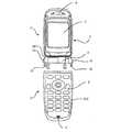
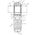
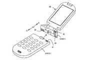
以下、図に基づいて本発明の実施形態を説明する。図1は第1の実施形態に係る折り畳み式の携帯電話の開いた状態を示す外観図であり、図2は図1の折り畳み式の携帯電話を、キーパネル部本体を有する第2本体と、表示パネル部とキーパネル部分割部とがヒンジを介して連結されてなる第1本体とに分割した状態を示す外観図である。図において、1はキーパネル部であり、上面にキーパネル2および通話用マイク3が配置されている。
第1の実施形態に係る折り畳み式の携帯電話は、互いに着脱可能な第1本体P及び第2本体Qを備えている。第1本体Pは、表示パネル部5、キーパネル部1のキーパネル部分割部1B及びヒンジ4を有している。第2本体Qは、キーパネル部1のキーパネル部本体1Aを有している。そして、第2本体Qにおけるキーパネル部本体1Aと第1本体Pにおけるキーパネル部分割部1Bとが連結されることにより、キーパネル部1が形成される。
第1本体Pにおいては、キーパネル部1のキーパネル部分割部1Bには、ヒンジ4を介して表示パネル部5が連結されている。表示パネル部5の上面には、通話用スピーカー6および表示画面7が配置されている。また、表示パネル部5の裏面にはカメラが配置されている。Hereinafter, embodiments of the present invention will be described with reference to the drawings. FIG. 1 is an external view showing an open state of a foldable mobile phone according to the first embodiment, and FIG. 2 shows a foldable mobile phone of FIG. 1as a second main body havinga key panelmain body, It is an external view which shows the state divided | segmented intothe 1st main body by which a display panel partand a key panel part division | segmentation part are connected via the hinge . In the figure,
The foldable mobile phone according to the first embodiment includes a first main body P and a second main body Q that are detachable from each other. The first main body P includes a
In the first main body P, the
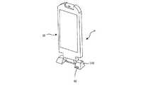
この折り畳み式の携帯電話は、図2に示されるように、キーパネル部1のヒンジ4の近くで分割可能に構成されている。図2の例では、分割部の両面に対向して磁石(図示せず)が配置され、磁石の吸着力により、着脱が可能となっている。なお、これらの磁石は一方を鉄片等の磁性金属に置き換えることも可能である。この分割部の対向する分割面には、図示しないが複数の端子がそれぞれ配置されており、第2本体Qと第1本体Pとが一体になっている状態でそれらの端子が互いに接触してキーパネル部1と表示パネル部5との信号伝達を可能にしている。なお、第2本体Qと第1本体Pとが分割された場合は、キーパネル部1と表示パネル部5とにそれぞれ送受信器を備えてキーパネル部1と表示パネル部5との間をブルートゥース(Bluetooth)等の無線により交信して両者間の信号伝達を可能にしている。また、キーパネル部1と表示パネル部5との間の信号伝達を無線によらず、電線で接続しておくことも可能である。As shown in FIG. 2, the foldable mobile phone is configured to be separable near the
また、第2本体Qと第1本体Pとが分割された場合に、キーパネル部1のキーパネル部本体1Aだけでの通話が可能なように、キーパネル部1のキーパネル部本体1Aの上端近くに通話用スピーカー(図示せず)が設けられている。このように構成したことで、第2本体Qと第1本体Pとが一体の場合は、従来の折り畳み式の携帯電話と同様に、通話用マイク3と通話用スピーカー6を用いて通話することが可能である。第2本体Qと第1本体Pとを分割した場合は、表示パネル部5を前方に置くか手に保持したままで、表示画面7を見ながら、あるいは表示パネル部5の裏面のカメラ(図示せず)により撮影しながら、耳にキーパネル部1のキーパネル部本体1Aを当てて通話することが可能となる。In addition, whenthe second main body Q andthe first main body P are divided,the key panel section
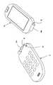
図3は第2の実施形態に係る折り畳み式の携帯電話の分割された状態を示す外観図であり、図4は図3で分割した第1本体Pを自立させた状態の背面図および側面図である。図3に示されるように、ヒンジ4の近くの両側面に、プッシュボタン11,12が設けられており、このプッシュボタン11,12をそれぞれ同時に押すと、その下方に突設されている爪13,14が連動して、第2本体Qの係合部との係合が解除されるように構成されている。FIG. 3 is an external view showing a divided state of the foldable mobile phone according to the second embodiment, and FIG. 4 is a rear view and a side view of the state wherethe first main body P divided in FIG. It is. As shown in FIG. 3,
また、第2本体Qと第1本体Pを連結する場合は、爪13,14を第2本体Qの係合部に挿入することで装着される。また、図4に示されるように、ヒンジ4の両側面にスタンド15が回動可能に取り付けられており、実線で示されるように下方に回動した状態で、表示パネル部5を含む第1本体Pが自立可能となり、テーブル、机、車のフロントパネル等の上に表示パネル部5を見やすい角度で置くことが可能となる。なお、スタンド15を不使用の場合は、破線で示すように、上方に回動させて表示パネル部5に密着させて置くことができる。また、図4(b)中の16はすべり止めのためのゴム板である。Further, when connectingthe second main body Q andthe first main body P , the
図5は第3の実施形態に係る折り畳み式の携帯電話の分割された状態を示す外観図である。この実施形態は、第2本体Qと第1本体Pとの着脱機構が図3と同一であり、異なる点は、表示画面を広くしたことである。従来機種の表示画面はLCDにより構成されておりバックライトを有する構造のため薄くするのに限界がある。そこで、本発明は、新たに、表示画面に有機ELディスプレイからなる表示パネルを用いることで薄型化を可能とし、さらに柔軟性が得られるため、表示画面を3面により構成し、それらを左右に展開および折り畳み可能にした。FIG. 5 is an external view showing a divided state of the foldable mobile phone according to the third embodiment. In this embodiment, the attachment / detachment mechanism betweenthe second main body Q andthe first main body P is the same as that in FIG. 3, and the difference is that the display screen is widened. Since the display screen of the conventional model is composed of an LCD and has a backlight, there is a limit to making it thin. Therefore, the present invention newly enables a reduction in thickness by using a display panel made of an organic EL display as a display screen, and further provides flexibility. Therefore, the display screen is configured with three surfaces, and these are arranged on the left and right. Made unfoldable and foldable.
すなわち図5に示すように、表示画面21〜23を有機ELディスプレイからなる表示パネルにより構成し、中央の表示画面21の左右に表示画面22,23を折り畳み可能に配置し、使用の際は表示画面22,23を左右に展開して3倍の広さにし、不使用時には折り畳んで表示画面21の大きさに収納する。このように画面を広くすることで表示画像の情報量が増大可能になる。また、携帯電話のカメラの画素数の増大やパノラマ化にも対応可能となる。 That is, as shown in FIG. 5, the display screens 21 to 23 are configured by a display panel made of an organic EL display, and the display screens 22 and 23 are arranged on the left and right sides of the
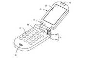
図6は第4の実施形態に係る折り畳み式の携帯電話を示す斜視図であり、図7は図6の携帯電話を分割した状態を示す斜視図であり、図8は図7で分割した表示パネル部を自立させた状態を示す斜視図である。図において、31はキーパネル部であり、上面にキーパネル32および通話用マイク33が配置されている。キーパネル部31には、ヒンジ34を介して表示パネル部35が連結されている。表示パネル部35の上面には、通話用スピーカー36および表示画面37が配置されている。また、表示パネル部35の裏面にはカメラが配置されている。
6 is a perspective view showing a foldable mobile phone according to the fourth embodiment, FIG. 7 is a perspective view showing a state in which the mobile phone of FIG. 6 is divided, and FIG. 8 is a display divided in FIG. It is a perspective view which shows the state which made the panel part self-supporting. In the figure,
この携帯電話は、ヒンジ34でヒンジピン34Aとヒンジ孔34Bとに分割可能である。分割する場合は、キーパネル部31側のロックボタン38をスライドさせて、ヒンジピン34Aとヒンジ孔34Bとの係合を解除して、表示パネル部35を右横方向に抜き取る。分割された表示パネル部35は、スタンド台39に装着して自立させることが可能である。キーパネル部31と表示パネル部35との間の信号伝達は、キーパネル部31の上端に配設された赤外線信号の送受信部41と、表示パネル部35の下端でヒンジ孔34Bのしたに配設された赤外線信号の送受信部42とにより行われる。表示パネル部35が、スタンド台39に装着されている間は、送受信部41とスタンド台39の前上部に設けられた赤外線信号の送受信部42とにより行われる。スタンド台39の上部右端には、スタンド台39から表示パネル部35から抜き取るときに係合を解除するための解除ボタン44が配置されている。
This mobile phone can be divided by a
また、キーパネル部31と表示パネル部35とが分割された場合に、キーパネル部31だけでの通話が可能なように、キーパネル部31の上端近くに通話用スピーカー(図示せず)が設けられている。このように構成したことで、キーパネル部31と表示パネル部35とが一体の場合は、従来の折り畳み式の携帯電話と同様に、通話用マイク33と通話用スピーカー36を用いて通話することが可能である。キーパネル部31と表示パネル部35とを分割した場合は、表示パネル部35をスタンド台39に装着して前方に置き、表示画面37を見ながら、あるいは表示パネル部35の裏面のカメラ(図示せず)により撮影しながら、耳にキーパネル部31を当てて通話することが可能となる。 In addition, when the
図9は第5の実施形態に係る折り畳み式の携帯電話を示す斜視図であり、図10は図9の携帯電話を分割した状態を示す斜視図であり、図11は図10で分割した第1本体を自立させた状態を示す斜視図である。図において、51はキーパネル部であり、上面にキーパネル52および通話用マイク53が配置されている。キーパネル部51には、ヒンジ54を介して表示パネル部55が連結されている。表示パネル部55の上面には、通話用スピーカー56および表示画面57が配置されている。また、表示パネル部55の裏面にはカメラが配置されている。Figure 9 is a perspective view showing a folding mobile phone according to the fifth embodiment, FIG. 10 is a perspective view showing a state of dividing the mobile phone of FIG 9,first and partitioned 11 10 It is a perspective view which shows the state which made1 main body self-support. In the figure,
この携帯電話は、ヒンジ54近くのキーパネル部51の上部で、キーパネル部本体51Aとキーパネル部分割部51Bとに分割可能である。分割する場合は、キーパネル部51のキーパネル部本体51A側のロックボタン58を押して、キーパネル部本体51Aとキーパネル部分割部51Bを引き離す。キーパネル部本体51Aとキーパネル部分割部51Bの当接面には、磁石59が埋設されており、これら磁石59の吸着力により、キーパネル部本体51Aとキーパネル部分割部51Bは一体に保持される。キーパネル部分割部51Bは、スタンドとして機能し、分割された表示パネル部55を含む第1本体Pを自立させることが可能である。キーパネル部51と表示パネル部55との間の信号伝達は、キーパネル部51のキーパネル部本体51Aの上端に配設された赤外線信号の送受信部61と、キーパネル部分割部51Bの分割面右上に設けられた赤外線信号の送受信部62とにより行われる。This mobile phone can be dividedinto a key panel portion
また、第2本体Qと第1本体Pとが分割された場合に、キーパネル部51のキーパネル部本体51Aだけでの通話が可能なように、キーパネル部51のキーパネル部本体51Aの上端近くに通話用スピーカー(図示せず)が設けられている。このように構成したことで、第2本体Qと第1本体Pとが一体の場合は、従来の折り畳み式の携帯電話と同様に、通話用マイク53と通話用スピーカー56を用いて通話することが可能である。第2本体Qと第1本体Pとを分割した場合は、表示パネル部55をキーパネル部分割部51Bにより自立させて前方に置き、表示画面57を見ながら、あるいは表示パネル部55の裏面のカメラ(図示せず)により撮影しながら、耳にキーパネル部51のキーパネル部本体51Aを当てて通話することが可能となる。In addition, whenthe second main body Q andthe first main body P are divided,the key panel section
なお、上述した各実施形態では、表示パネル部5,35,55の背面にカメラが配置されていたが、表示パネル部5,35,55の前面に配置して、通話者の顔を撮影可能にすると、双方向で相手の顔を見ながら通話する、いわゆるテレビ電話ともなる。
In each of the above-described embodiments, the camera is disposed on the back surface of the
なお、本発明の構成では、キーパネル部1,31,51と表示パネル部5,35,55を分割し両者間の信号伝送を無線とした場合、キーパネル部1,31,51と表示パネル部5,35,55にも電源が必要となる。そこで、キーパネル部1,31,51と表示パネル部5,35,55の両方にバッテリを備えるものとする。これらのバッテリへの充電は、キーパネル部1,31,51のキーパネル部本体を有する第2本体Qと、表示パネル部5,35,55を含む第1本体Pを連結した状態で、2個のバッテリを同時に充電するように構成する。In the configuration of the present invention, when the
また、上述の各実施形態では、キーパネル部1,31,51のキーパネル部本体を有する第2本体Qと、表示パネル部5,35,55を含む第1本体Pとを分割した場合について説明したが、第2本体Qと第1本体Pを連結させた状態では、従来機種と同様な使用が可能である。Further, in the embodiments described above, and asecond body Q having a key panel body of the
本発明は、ヒンジにより開閉する折り畳み式の携帯電話以外に、側方へ回動させる畳み式の携帯電話、および折り畳み式でないストレート型の携帯電話にも利用可能である。 The present invention can be used not only for a foldable mobile phone that is opened and closed by a hinge, but also for a foldable mobile phone that is rotated sideways and a straight-type mobile phone that is not foldable.
1 キーパネル部
2 キーパネル
3 通話用マイク
4 ヒンジ
5 表示パネル部
6 通話用スピーカー
7 表示画面
11,12 プッシュボタン
13,14 爪
15 スタンド
16 ゴム板
21〜23 表示画面
31 キーパネル部
32 キーパネル
33 通話用マイク
34 ヒンジ
34A ヒンジピン
34B ヒンジ孔
35 表示パネル部
36 通話用スピーカー
37 表示画面
38 ロックボタン
39 スタンド台
41〜43 送受信部
44 解除ボタン
51 キーパネル部
51A キーパネル部本体
51B キーパネル部上端
52 キーパネル
53 通話用マイク
54 ヒンジ
55 表示パネル部
56 通話用スピーカー
57 表示画面
58 ロックボタン
59 磁石
61,62 送受信部DESCRIPTION OF
31 Key panel
32 key panel
33 Microphone for calls
34 Hinge
34A Hinge Pin
34B Hinge hole
35 Display panel
36 Speaker for calls
37 Display screen
38 Lock button
39 Stand stand
41-43 transceiver
44 Release button
51 Key panel
51A Key panel body
51B Key panel top edge
52 key panel
53 Microphone for calls
54 Hinge
55 Display panel
56 Speaker for call
57 Display screen
58 Lock button
59 Magnet
61, 62 Transceiver
Claims (13)
Translated fromJapanese通話用マイクおよび第2通話用スピーカーが配置されるキーパネル部本体を有する第2本体と、を備える携帯電話であって、
前記第1本体と前記第2本体とは、互いに着脱可能であると共に、有線または無線により信号伝達可能に構成されることを特徴とする携帯電話。A display panel unit in which a first call speaker and a display screen are arranged on one side and a camera is arranged on a side opposite to the one side, and a key panel unit dividing unit arranged on one end side of the display panel unit A first body having a hinge that connects the display panel part and the key panel part split part so as to be openable and closable,
A second main body having a key panel portion main body on which a call microphone and a second call speaker are arranged,
The mobile phone characterized in that the first main body and the second main body are detachable from each other and are configured to be able to transmit signals by wire or wirelessly.
前記キーパネル部本体と前記キーパネル部分割部とが連結されることによりキーパネル部が形成され、
前記キーパネル部が形成された状態において、前記表示パネル部と前記キーパネル部とが開閉可能に構成されることを特徴とする携帯電話。The mobile phone according to claim 1, wherein
A key panel part is formed by connecting the key panel part main body and the key panel part dividing part,
A mobile phone, wherein the display panel unit and the key panel unit are configured to be openable and closable in a state where the key panel unit is formed.
前記第1本体は、前記第2本体と分割された状態で、前記キーパネル部分割部をスタンドにして自立可能となっていることを特徴とする携帯電話。The mobile phone according to claim 1 or 2,
The mobile phone according to claim 1, wherein the first main body is independent from the second main body with the key panel section dividing section as a stand.
前記キーパネル部本体に爪が設けられ、前記キーパネル部分割部に前記爪との係合部が設けられており、前記爪と係合部とが着脱自在に係合することを特徴とする携帯電話。The mobile phone according to claim 1 or 2,
A claw is provided in the key panel main body, an engagement portion with the claw is provided in the key panel division portion, and the claw and the engagement portion are detachably engaged. mobile phone.
前記キーパネル部分割部に爪が設けられ、前記キーパネル部本体に前記爪との係合部が設けられており、前記爪と係合部とが着脱自在に係合することを特徴とする携帯電話。The mobile phone according to claim 1 or 2,
The key panel portion dividing portion is provided with a claw, the key panel portion main body is provided with an engaging portion with the claw, and the claw and the engaging portion are detachably engaged. mobile phone.
前記表示パネル部を左右に展開および折り畳みが可能な3面の表示パネルにより構成したことを特徴とする携帯電話。The mobile phone according to any one of claims 1 to5 ,
A cellular phone characterized in that the display panel portion is constituted by a three-sided display panel that can be expanded and folded left and right.
前記表示パネルを有機ELディスプレイにより構成したことを特徴とする携帯電話。The mobile phone according to claim6 , wherein
A mobile phone characterized in that the display panel comprises an organic EL display.
前記キーパネル部本体および前記キーパネル部分割部における対向する分割面にそれぞれ磁石が配設されており、前記磁石の吸着力により前記キーパネル部本体と前記キーパネル部分割部とが着脱自在となっていることを特徴とする携帯電話。The mobile phone according to claim 1or 2 ,
Magnets are respectively arranged on opposing dividing surfaces of the key panel main body and the key panel dividing portion, and the key panel main body and the key panel dividing portion are detachable by an attractive force of the magnet. A mobile phone characterized by
前記磁石の一方を磁性金属に置き換えたことを特徴とする携帯電話。The mobile phone according to claim8 ,
A mobile phone characterized in that one of the magnets is replaced with a magnetic metal.
前記表示パネル部の後面下部に折り畳み式スタンドを備えたことを特徴とする携帯電話。The mobile phone according to claim 1or 2 ,
A mobile phone comprising a foldable stand at a lower rear portion of the display panel portion.
前記キーパネル部本体および前記キーパネル部分割部における対向する分割面にそれぞれ赤外線信号の送受信部を配設したことを特徴とする携帯電話。The mobile phone according to any one of claims 1 to10 ,
An infrared signal transmission / reception unit is provided on each of the opposing division surfaces of the key panel main body and the key panel division unit.
前記表示パネル部および前記キーパネル部本体のそれぞれにバッテリを内蔵したことを特徴とする携帯電話。The mobile phone according to any one of claims 1 to11 ,
A mobile phone comprising a battery built in each of the display panel unit and the key panel unit main body.
前記表示パネル部の前面に更にカメラを配置したことを特徴とする携帯電話。The mobile phone according to any one of claims 1 to12 ,
A mobile phone characterized in that a camera is further arranged in front of the display panel section.
Priority Applications (1)
| Application Number | Priority Date | Filing Date | Title |
|---|---|---|---|
| JP2004069148AJP4071727B2 (en) | 2003-03-14 | 2004-03-11 | mobile phone |
Applications Claiming Priority (2)
| Application Number | Priority Date | Filing Date | Title |
|---|---|---|---|
| JP2003071050 | 2003-03-14 | ||
| JP2004069148AJP4071727B2 (en) | 2003-03-14 | 2004-03-11 | mobile phone |
Publications (3)
| Publication Number | Publication Date |
|---|---|
| JP2004304784A JP2004304784A (en) | 2004-10-28 |
| JP2004304784A5 JP2004304784A5 (en) | 2007-06-21 |
| JP4071727B2true JP4071727B2 (en) | 2008-04-02 |
Family
ID=33421719
Family Applications (1)
| Application Number | Title | Priority Date | Filing Date |
|---|---|---|---|
| JP2004069148AExpired - Fee RelatedJP4071727B2 (en) | 2003-03-14 | 2004-03-11 | mobile phone |
Country Status (1)
| Country | Link |
|---|---|
| JP (1) | JP4071727B2 (en) |
Families Citing this family (17)
| Publication number | Priority date | Publication date | Assignee | Title |
|---|---|---|---|---|
| JP2007116252A (en)* | 2005-10-18 | 2007-05-10 | Seiko Epson Corp | Wireless communication device |
| CN100505994C (en)* | 2005-11-24 | 2009-06-24 | 宏达国际电子股份有限公司 | Automatic alignment connecting mechanism for electronic device and auxiliary equipment |
| JP4907404B2 (en)* | 2007-03-29 | 2012-03-28 | 京セラ株式会社 | Electronics |
| JP5029549B2 (en)* | 2008-09-18 | 2012-09-19 | 富士通株式会社 | Electronics |
| CN102223424A (en)* | 2010-04-16 | 2011-10-19 | 鸿富锦精密工业(深圳)有限公司 | Mobile phone |
| US8390412B2 (en)* | 2010-09-17 | 2013-03-05 | Apple Inc. | Protective cover |
| US8242868B2 (en) | 2010-09-17 | 2012-08-14 | Apple Inc. | Methods and apparatus for configuring a magnetic attachment system |
| US8143982B1 (en) | 2010-09-17 | 2012-03-27 | Apple Inc. | Foldable accessory device |
| US8264310B2 (en)* | 2010-09-17 | 2012-09-11 | Apple Inc. | Accessory device for peek mode |
| EP2616896A4 (en) | 2010-09-17 | 2016-10-19 | Apple Inc | SENSOR FUSION |
| US8253518B2 (en) | 2010-09-17 | 2012-08-28 | Apple Inc. | Foldable cover for electronic device |
| US8344836B2 (en) | 2010-09-17 | 2013-01-01 | Apple Inc. | Protective cover for a tablet computer |
| US8390411B2 (en) | 2010-09-17 | 2013-03-05 | Apple Inc. | Tablet device |
| US8395465B2 (en) | 2010-09-17 | 2013-03-12 | Apple Inc. | Cover for an electric device |
| US8289115B2 (en) | 2010-09-17 | 2012-10-16 | Apple Inc. | Sensor fusion |
| JP2014153892A (en)* | 2013-02-07 | 2014-08-25 | Sii Data Service Kk | Portable information processing device |
| WO2015147885A1 (en)* | 2014-03-28 | 2015-10-01 | Intel Corporation | Adjustment of magnetic force in a computing device |
- 2004
- 2004-03-11JPJP2004069148Apatent/JP4071727B2/ennot_activeExpired - Fee Related
Also Published As
| Publication number | Publication date |
|---|---|
| JP2004304784A (en) | 2004-10-28 |
Similar Documents
| Publication | Publication Date | Title |
|---|---|---|
| JP4071727B2 (en) | mobile phone | |
| CN100558118C (en) | Folding communication terminal device | |
| KR100476608B1 (en) | Cellular phone with imaging device | |
| EP1455505A1 (en) | Foldable portable terminal with a camera module | |
| TWD121254S1 (en) | Handset | |
| JPH10313452A (en) | Portable radio communication equipment | |
| JP4708294B2 (en) | Portable electronic devices | |
| JP3616798B2 (en) | Communication terminal device and captured image display method | |
| JP4393750B2 (en) | Openable mobile terminal device | |
| JP2005229349A (en) | Mobile phone with removable display | |
| WO2012039173A1 (en) | Communication terminal mount comprising receiver | |
| JP2004120056A (en) | Portable telephone with television telephony function | |
| JP3574110B2 (en) | Open / close communication terminal | |
| JP4440289B2 (en) | Openable mobile terminal device | |
| JP4213495B2 (en) | Mobile device | |
| KR100605492B1 (en) | Double sided folder mobile phone | |
| US20060245152A1 (en) | Handheld electronic device casing element | |
| JP3574109B2 (en) | Open / close communication terminal | |
| JP4332021B2 (en) | Communication terminal device and image display method | |
| JP4280088B2 (en) | Communication terminal device | |
| KR100556881B1 (en) | Portable terminal with remote control connection and remote control unit for portable terminal | |
| JP3616799B2 (en) | Open / close communication terminal device | |
| KR200420561Y1 (en) | Portable terminal structure | |
| KR200233060Y1 (en) | Seperating kit about the IMT-2000 image phone | |
| JP2006166085A (en) | Portable communications terminal |
Legal Events
| Date | Code | Title | Description |
|---|---|---|---|
| A621 | Written request for application examination | Free format text:JAPANESE INTERMEDIATE CODE: A621 Effective date:20060224 | |
| A521 | Written amendment | Free format text:JAPANESE INTERMEDIATE CODE: A523 Effective date:20070426 | |
| A871 | Explanation of circumstances concerning accelerated examination | Free format text:JAPANESE INTERMEDIATE CODE: A871 Effective date:20070426 | |
| RD02 | Notification of acceptance of power of attorney | Free format text:JAPANESE INTERMEDIATE CODE: A7422 Effective date:20070426 | |
| A975 | Report on accelerated examination | Free format text:JAPANESE INTERMEDIATE CODE: A971005 Effective date:20070627 | |
| A131 | Notification of reasons for refusal | Free format text:JAPANESE INTERMEDIATE CODE: A131 Effective date:20070710 | |
| A521 | Written amendment | Free format text:JAPANESE INTERMEDIATE CODE: A523 Effective date:20070904 | |
| A131 | Notification of reasons for refusal | Free format text:JAPANESE INTERMEDIATE CODE: A131 Effective date:20071113 | |
| A521 | Written amendment | Free format text:JAPANESE INTERMEDIATE CODE: A523 Effective date:20071130 | |
| TRDD | Decision of grant or rejection written | ||
| A01 | Written decision to grant a patent or to grant a registration (utility model) | Free format text:JAPANESE INTERMEDIATE CODE: A01 Effective date:20080108 | |
| A61 | First payment of annual fees (during grant procedure) | Free format text:JAPANESE INTERMEDIATE CODE: A61 Effective date:20080117 | |
| R150 | Certificate of patent or registration of utility model | Free format text:JAPANESE INTERMEDIATE CODE: R150 | |
| FPAY | Renewal fee payment (event date is renewal date of database) | Free format text:PAYMENT UNTIL: 20110125 Year of fee payment:3 | |
| S111 | Request for change of ownership or part of ownership | Free format text:JAPANESE INTERMEDIATE CODE: R313113 | |
| FPAY | Renewal fee payment (event date is renewal date of database) | Free format text:PAYMENT UNTIL: 20110125 Year of fee payment:3 | |
| R350 | Written notification of registration of transfer | Free format text:JAPANESE INTERMEDIATE CODE: R350 | |
| FPAY | Renewal fee payment (event date is renewal date of database) | Free format text:PAYMENT UNTIL: 20110125 Year of fee payment:3 | |
| FPAY | Renewal fee payment (event date is renewal date of database) | Free format text:PAYMENT UNTIL: 20120125 Year of fee payment:4 | |
| S531 | Written request for registration of change of domicile | Free format text:JAPANESE INTERMEDIATE CODE: R313532 | |
| S533 | Written request for registration of change of name | Free format text:JAPANESE INTERMEDIATE CODE: R313533 | |
| R350 | Written notification of registration of transfer | Free format text:JAPANESE INTERMEDIATE CODE: R350 | |
| FPAY | Renewal fee payment (event date is renewal date of database) | Free format text:PAYMENT UNTIL: 20130125 Year of fee payment:5 | |
| LAPS | Cancellation because of no payment of annual fees |