JP4071325B2 - Portable computer equipment - Google Patents
Portable computer equipmentDownload PDFInfo
- Publication number
- JP4071325B2 JP4071325B2JP28560397AJP28560397AJP4071325B2JP 4071325 B2JP4071325 B2JP 4071325B2JP 28560397 AJP28560397 AJP 28560397AJP 28560397 AJP28560397 AJP 28560397AJP 4071325 B2JP4071325 B2JP 4071325B2
- Authority
- JP
- Japan
- Prior art keywords
- housing
- coupling mechanism
- modular unit
- lock
- display
- Prior art date
- Legal status (The legal status is an assumption and is not a legal conclusion. Google has not performed a legal analysis and makes no representation as to the accuracy of the status listed.)
- Expired - Fee Related
Links
Images


Classifications
- E—FIXED CONSTRUCTIONS
- E05—LOCKS; KEYS; WINDOW OR DOOR FITTINGS; SAFES
- E05B—LOCKS; ACCESSORIES THEREFOR; HANDCUFFS
- E05B73/00—Devices for locking portable objects against unauthorised removal; Miscellaneous locking devices
- E05B73/0082—Devices for locking portable objects against unauthorised removal; Miscellaneous locking devices for office machines, e.g. PC's, portable computers, typewriters, calculators
- G—PHYSICS
- G06—COMPUTING OR CALCULATING; COUNTING
- G06F—ELECTRIC DIGITAL DATA PROCESSING
- G06F1/00—Details not covered by groups G06F3/00 - G06F13/00 and G06F21/00
- G06F1/16—Constructional details or arrangements
- G—PHYSICS
- G06—COMPUTING OR CALCULATING; COUNTING
- G06F—ELECTRIC DIGITAL DATA PROCESSING
- G06F1/00—Details not covered by groups G06F3/00 - G06F13/00 and G06F21/00
- G06F1/16—Constructional details or arrangements
- G06F1/1613—Constructional details or arrangements for portable computers
- G06F1/1615—Constructional details or arrangements for portable computers with several enclosures having relative motions, each enclosure supporting at least one I/O or computing function
- G06F1/1616—Constructional details or arrangements for portable computers with several enclosures having relative motions, each enclosure supporting at least one I/O or computing function with folding flat displays, e.g. laptop computers or notebooks having a clamshell configuration, with body parts pivoting to an open position around an axis parallel to the plane they define in closed position
- G—PHYSICS
- G06—COMPUTING OR CALCULATING; COUNTING
- G06F—ELECTRIC DIGITAL DATA PROCESSING
- G06F1/00—Details not covered by groups G06F3/00 - G06F13/00 and G06F21/00
- G06F1/16—Constructional details or arrangements
- G06F1/1613—Constructional details or arrangements for portable computers
- G06F1/1632—External expansion units, e.g. docking stations
- G—PHYSICS
- G06—COMPUTING OR CALCULATING; COUNTING
- G06F—ELECTRIC DIGITAL DATA PROCESSING
- G06F1/00—Details not covered by groups G06F3/00 - G06F13/00 and G06F21/00
- G06F1/16—Constructional details or arrangements
- G06F1/1613—Constructional details or arrangements for portable computers
- G06F1/1633—Constructional details or arrangements of portable computers not specific to the type of enclosures covered by groups G06F1/1615 - G06F1/1626
- G06F1/1656—Details related to functional adaptations of the enclosure, e.g. to provide protection against EMI, shock, water, or to host detachable peripherals like a mouse or removable expansions units like PCMCIA cards, or to provide access to internal components for maintenance or to removable storage supports like CDs or DVDs, or to mechanically mount accessories
- G—PHYSICS
- G06—COMPUTING OR CALCULATING; COUNTING
- G06F—ELECTRIC DIGITAL DATA PROCESSING
- G06F1/00—Details not covered by groups G06F3/00 - G06F13/00 and G06F21/00
- G06F1/16—Constructional details or arrangements
- G06F1/1613—Constructional details or arrangements for portable computers
- G06F1/1633—Constructional details or arrangements of portable computers not specific to the type of enclosures covered by groups G06F1/1615 - G06F1/1626
- G06F1/1675—Miscellaneous details related to the relative movement between the different enclosures or enclosure parts
- G06F1/1679—Miscellaneous details related to the relative movement between the different enclosures or enclosure parts for locking or maintaining the movable parts of the enclosure in a fixed position, e.g. latching mechanism at the edge of the display in a laptop or for the screen protective cover of a PDA
- E—FIXED CONSTRUCTIONS
- E05—LOCKS; KEYS; WINDOW OR DOOR FITTINGS; SAFES
- E05B—LOCKS; ACCESSORIES THEREFOR; HANDCUFFS
- E05B37/00—Permutation or combination locks; Puzzle locks
- E05B37/02—Permutation or combination locks; Puzzle locks with tumbler discs or rings arranged on a single axis, each disc being adjustable independently of the others
- Y—GENERAL TAGGING OF NEW TECHNOLOGICAL DEVELOPMENTS; GENERAL TAGGING OF CROSS-SECTIONAL TECHNOLOGIES SPANNING OVER SEVERAL SECTIONS OF THE IPC; TECHNICAL SUBJECTS COVERED BY FORMER USPC CROSS-REFERENCE ART COLLECTIONS [XRACs] AND DIGESTS
- Y10—TECHNICAL SUBJECTS COVERED BY FORMER USPC
- Y10T—TECHNICAL SUBJECTS COVERED BY FORMER US CLASSIFICATION
- Y10T70/00—Locks
- Y10T70/50—Special application
- Y10T70/5009—For portable articles
Landscapes
- Engineering & Computer Science (AREA)
- Theoretical Computer Science (AREA)
- Computer Hardware Design (AREA)
- Physics & Mathematics (AREA)
- General Engineering & Computer Science (AREA)
- Human Computer Interaction (AREA)
- General Physics & Mathematics (AREA)
- Mathematical Physics (AREA)
- Casings For Electric Apparatus (AREA)
- Input From Keyboards Or The Like (AREA)
- Power Sources (AREA)
Description
Translated fromJapanese【0001】
【発明の属する技術分野】
本発明は、ポータブルコンピュータに係り、とりわけポータブルコンピュータへのアクセスを機密保護するための技術に関する。
【0002】
【従来の技術】
さまざまなコンピュータアプリケーションに使用される汎用コンピュータおよび特殊コンピュータには多くのタイプがある。パーソナルコンピュータおよびコンピュータワークステーションは、いくつかの異なるプロセッサ(例えば80386、80486、586、PENTIUMTM、PowerPCTM、Alpha)およびオペレーティングシステム(例えばDOS、Windows95、WindowsNT、UNIX、MAC−OS、OS/2)の中の任意のものを有する多くの異なる構成で利用することができる一般的なコンピュータシステムアーキテクチャである。ケースサイズによって分類したさまざまな種類には、デスクトップコンピュータ、ラップトップコンピュータ、ノートブックコンピュータ、およびパームトップコンピュータすなわちハンドヘルドコンピュータが含まれる。ラップトップ、ノートブック、およびパームトップすなわちハンドヘルドコンピュータはまた、ポータブルコンピュータとも呼ばれる。
【0003】
ポータブルコンピュータは、ユーザの移動性を向上させることができる一般的な構成である。通常は、プロセッサボード、ディスプレイ、およびキーボードは共通のケースと一体化される。ノートブックコンピュータのケースは、通常は互いに蝶番式に恒常的に取り付けられたディスプレイハウジングおよびキーボードハウジングを含む。フラットパネルディスプレイは、ディスプレイハウジング内に取り付けられる。キーボード、マザーボード、データ記憶ユニット、拡張スロット、およびI/Oポートは、キーボードハウジング内に取り付けられる。フロッピーディスクドライブ、ハードディスクドライブ、CD−ROMドライブ、およびモデムなどのモジュラ周辺ユニット、またはその他のPCカードは、容易にこのケースに取り付けられ、このケースから取り外される。従来のノートブックコンピュータのサイズは、ほぼ標準的な紙1枚の大きさ(例えば21.6×27.9cm、また英単位では8.5×11.0インチ)であり、重量は6ポンド以下である。このようなノートブックコンピュータの厚さは、通常は4.5cm乃至6.0cmである。ノートブックコンピュータは、小型かつ軽量であることおよびその一体化されているという性質から、容易に移送することができるようになった。ただし、このような特性により、このコンピュータおよびそのモジュラユニットは、容易に盗まれる標的にもなった。したがって、ポータブルコンピュータおよびそのモジュラユニットの盗難を阻止することが求められている。
【0004】
【発明が解決しようとする課題】
個人、企業、および施設は、さまざまなタスクを実行するためにますますポータブルコンピュータに頼るようになっている。このコンピュータは、しばしばデータ入力端末、通信装置、情報記憶センタ、および/または情報処理センタとして働く。各コンピュータに記憶された情報は、しばしばコンピュータ自体の価値を超える。したがって、ポータブルコンピュータおよびその記憶されたデータへの無許可アクセスを防止することが求められている。
【0005】
【課題を解決するための手段】
本発明は、ポータブルコンピュータ、およびそのモジュラユニットや装置、構成部品へのアクセスを制限する、物理的機密保護措置を対象とする。本発明によれば、ポータブルコンピュータは、ディスプレイおよびシステムユニットを合わせて(例えば「クラムシェル」の形状で)ロックする、物理的機密保護装置を含む。この機密保護装置はまた、周辺装置の取り外しを防止し、コンピュータのキーボードおよびマウスからの入力を不可能とする。いくつかの作用形態では、この機密保護装置はまた、コンピュータのエネルギ消費の増加、およびドッキングステーションからのコンピュータの取り外しも防止する。
【0006】
本発明の一態様によれば、このコンピュータはロック状態か、またはロック解除状態かのどちらかで配置される。ロック状態では、周辺装置はコンピュータケース中にロックされ、キーボードおよびマウスはディスエーブル(使用不可能)になっている。コンピュータケースが閉じると、このケースもまた開かないようになる。
【0007】
本発明の別の態様によれば、連結機構はロック状態を規定するロック位置とロック解除状態を規定するロック解除位置の間を移動する。かぎ鎖錠器または組合せ鎖錠器(例えばタンブラ、キーパッド)は、連結機構をロック位置に固定する。ユーザは、かぎ鎖錠器または組合せ鎖錠器をロック解除して、連結機構をロック位置からロック解除位置に移動させる。いくつかの実施形態では、かぎを回す、または正しい組合せを入力すると、連結機構は自動的にロック解除位置に移動する。逆に、ロック解除位置からロック位置にユーザが連結機構を移動させると、いくつかの実施形態のかぎ鎖錠器または組合せ鎖錠器は自動的にロックする。この機密保護システムの1つの利点は、単一の動作(例えば連結機構をロック位置に移動させる)を行うことで、クラムシェルをロックし、周辺ユニットを定位置にロックし、キーボードおよびマウスをディスエーブルすることになる点である。同様に、単一の動作(例えば、かぎ鎖錠器または組合せ鎖錠器をロック解除する)を行うことで、機密保護措置を停止することになる(例えばクラムシェルをロック解除し、周辺ユニットをロック解除し、キーボードおよびマウスをイネーブル(使用可能)にする)。
【0008】
本発明の別の態様によれば、電源オンのままコンピュータをロック状態にした場合には、ユーザは依然として各ポート(マウスポートは除く)にアクセスすることができる。したがって、ユーザはこのコンピュータに、電子メールの検索、自動バックアップの実行、ファックス伝送の待機などの無人機能を実行させることができる。影響を受けない外部通信は、LAN接続、モデム接続、ドッキング接続、またはその他のポート接続を介して起こる。
【0009】
本発明の別の態様によれば、ユーザは、コンピュータがロック状態にある間、システムのオン/オフボタンを通常通り機能するままにしておくか、またはこのオン/オフボタンをディスエーブルするかを指定することができる。通常通り機能するままにしておくと、ユーザは電源をオンにし、LAN接続、モデム接続、ドッキング接続、またはその他のポート接続を介した外部通信をイネーブルにすることができる。
【0010】
本発明の別の態様によれば、ポータブルコンピュータは、ロック状態にある間はドッキングユニットからロック解除されないようになっている。
【0011】
好ましい実施形態によれば、ポータブルコンピュータは、第1ハウジング、第2ハウジング、鎖錠器、および連結機構を含む。ディスプレイパネルは第1ハウジングに取り付けられる。キーボード、処理ユニット、およびモジュラユニットは第2ハウジングに取り付けられる。好ましい実施形態では、鎖錠器および連結機構もまた、第2ハウジングに取り付けられる。第2ハウジングは開口を画定する。モジュラユニットは、この開口に着脱可能に挿入される。第1ハウジングは、ディスプレイパネルを見るための開いた位置と、ディスプレイパネルが第2ハウジングに保持される閉じた位置との間で、第2ハウジングに対して移動する。鎖錠器は、所定の時間で、ロック状態か、またはロック解除状態のどちらかを規定する。連結機構は鎖錠器に結合される。連結機構は、第1位置と第2位置との間を移動する。連結機構は、第1位置にある間、モジュラユニットの取り外しを阻止または制限、そうでなければ防止する。連結機構はまた、第1ハウジングが閉じた位置にあり、連結機構が第1位置にある場合には、第1ハウジングが第2ハウジングに対して開くのを防止する。連結機構は、鎖錠器がロック状態を規定している間は、第2位置に移動しないようになっている。連結機構は、鎖錠器がロック解除状態に切り替わると、自動的に第2位置に移動する。
【0012】
このコンピュータ装置はまた、ユーザがこのコンピュータ装置にコマンドを入力するための入力装置、および連結機構が第1位置にある間、キーボードおよび入力装置をディスエーブルする第1回路も含む。第1回路は、連結機構が第2位置にある間は、キーボードおよび入力装置をイネーブルにする。第2回路は、連結機構が第1位置にある間、このコンピュータ装置の構成部品(例えばオン/オフスイッチ)を任意選択でディスエーブルする。第3回路には、コンピュータ装置がドッキングステーションからロック解除されるのを妨げる第1状態と、コンピュータ装置がドッキングステーションからロック解除されるのを妨げない第2状態とがある。第3回路は、連結機構が第1位置にある間は第1状態にあり、連結機構が第2位置にある間は第2状態にある。
【0013】
連結機構は、スライドボタンおよびリンクを含む。スライドボタンは、スイッチの第1位置およびスイッチの第2位置を規定する。リンクは連結機構の第1位置と連結機構の第2位置との間を移動する。連結機構はまた、連結機構が第1位置にある間、モジュラユニットの取り外しを阻止または制限、そうでなければ防止する、リンクに対して固定された第1部材も含む。リンクに対して固定された第2部材は、第1ハウジングが第2ハウジングに対して閉じた位置にあり、連結機構が第1位置にある間、第1ハウジングの閉じた位置からの移動を阻止または制限、そうでなければ防止する。リンクの第1位置はスイッチの第1位置と一致し、リンクの第2位置はスイッチの第2位置と一致する。
【0014】
ポータブルコンピュータ装置へのアクセスを機密保護する方法は、連結機構を第1位置に移動させることによってコンピュータ装置に対するロック状態を規定するステップと、ロック解除状態に鎖錠器を切り替えることによってコンピュータ装置に対するロック解除状態を規定するステップとを含む。第1位置にある間、連結機構はモジュラユニットの取り外しを阻止または制限、そうでなければ防止し、さらに第1ハウジングが閉じた位置にあるときには第1ハウジングが第2ハウジングに対して開くのを防止する。第1回路は、連結機構が第1位置に移動する際に第1状態に切り替わり、キーボードおよび入力装置をディスエーブルする。連結機構は、鎖錠器がロック状態を規定する間は、第2位置に移動しないようになっている。第2位置にある間、連結機構はモジュラユニットの取り外しを防止せず、第1ハウジングが第2ハウジングに対して開くのを防止しない。第1回路は、連結機構が第2位置に移動する際に、第2状態に切り替わる。第2状態にある間、第1回路はもはやキーボードおよび指示装置をディスエーブルしない。
【0015】
この方法の別のステップは、第2回路をイネーブルにするか、またはディスエーブルにするか、どちらか一方を行うようにコンピュータ装置を構成するステップを含む。ロック状態を規定するステップは、第2回路がイネーブルになったときに、第2回路を第1状態にするステップを含む。第2回路が第1状態にある間、コンピュータ装置を起動するオン/オフスイッチはディスエーブルされている。
【0016】
第3回路には、コンピュータ装置がドッキングステーションからドッキング解除されるのを妨げる第1状態と、コンピュータ装置がドッキングステーションからドッキング解除されるのを妨げない第2状態とがある。第3回路は、連結機構が第1位置にある間は第1状態にあり、連結機構が第2位置にある間は第2状態にある。ロック状態を規定するステップは、第3回路を第1状態にするステップを含む。ロック解除状態を規定するステップは、第3回路を第2状態にするステップを含む。
【0017】
本発明の1つの利点は、簡単な動作を実行すれば、コンピュータがロック状態またはロック解除状態に切り替わる点である(例えばスライドボタンを移動させる、またはスライドボタンを移動させて鎖錠器をセットする)。もう1つの利点は、機密保護措置が活動状態にある間にも、ユーザが依然として無人機能を実行させることがことができる点である。もう1つの利点は、(すなわちコンピュータがロック状態に入ったとき)その機密保護システムによってディスエーブルすべき任意選択の構成部品を選択できるように、ユーザが何らかの機密保護措置を構成することができる点である。本発明の上記その他の態様および利点は、添付の図面に関連する以下の詳細な説明を参照することにより、よりよく理解されるであろう。
【0018】
【発明の実施の形態】
(概要)
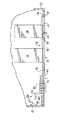
図1および図2は、本発明の一実施形態によるポータブルコンピュータを示す図である。ポータブルコンピュータは、ノートブックコンピュータ、ラップトップコンピュータ、ハンドヘルドコンピュータ、携帯情報端末、またはその他の汎用または特殊ポータブルコンピュータ装置である。ポータブルコンピュータは、処理ユニット(図示せず)と、ケース16に一体化されたフラットパネルディスプレイ12およびキーボード14とを含む。ノートブックコンピュータの実施形態の場合は、ケース16は互いに蝶番式に取り付けられたディスプレイハウジング18およびキーボードハウジング20を含む。フラットパネルディスプレイ12はディスプレイハウジング18内に取り付けられる。キーボード14、マザーボード、およびI/Oポートは、キーボードハウジング20中に取り付けられる。バッテリ、フロッピーディスクドライブ、ハードディスクドライブ、CD−ROMドライブおよびモデムなどのモジュラユニット、またはその他のPCカードは、開口22、24を介して容易にキーボードハウジング20に取り付けられ、そこから取り外される。図2は、モジュラユニットであるハードディスクドライブ26およびモデム28が開口22、24内に取り付けられたノートブックコンピュータ10を示す図である。
【0019】
本発明の一態様によれば、鎖錠器30は、キーボードハウジング20内に取り付けられる。鎖錠器30には、キーボードハウジング20の一面からアクセスすることができる。図示した実施形態では、前面32から鎖錠器30を操作することができる。実施形態によって、鎖錠器はかぎ鎖錠器、組合せ鎖錠器、または電子キーパッド鎖錠器になる。機械タンブラ、継電器、またはその他の従来型のあるいは開発中の鎖錠器構造が、内部の鎖錠器構成部品を規定する。図示したのは、4エントリ組合せに応答するタンブラ34〜37を備えた、機械式組合せ鎖錠器である。前面32に、スライドボタン40も示す。スライドボタン40はロック解除位置42(図1に示す)とロック位置44(図2に示す)の間を移動する。スライドボタン40は、ロック解除位置42からロック位置44までは、鎖錠器30の状態とは無関係に移動することができる。しかし、スライドボタン40がロック位置44からロック解除位置42まで移動することができるのは、タンブラ34〜37が正しい組合せにセットされている(または、例えばかぎがかぎ鎖錠器をロック解除位置に回す、あるいはキーパッド鎖錠器が正しいエントリシーケンスを受信する)時のみである。スライドボタン40をロック位置44に切り替えると、ノートブックコンピュータ10はロック状態に置かれる。スライドボタン40をロック解除位置42に切り替えると、ノートブックコンピュータ10はロック解除状態に置かれる。
【0020】
好ましい実施形態では、スライドボタン40は、ロック解除位置に向けて移動される。ユーザが鎖錠器30をロック解除すると、スライドボタン40は自動的にロック解除位置42に移動する。逆に、ユーザがスライドボタン40をロック位置44に移動させると、いくつかの実施形態では鎖錠器30は自動的にロック状態に変化する(例えばタンブラが動く、かぎ鎖錠器が回転する、またはキーパッド鎖錠器の内部構造がロックする)。いくつかの実施形態では、スライドボタン40がロック位置44に移動しても、鎖錠器30は自動的にロック状態に変化しない。その代わりに、ユーザが手動で、鎖錠器タンブラ34〜37を変化させるか、またはかぎを回す。スライドボタン40を示したが、別の機械的、電気的、または光学的な、スイッチ、ボタン、またはラッチが、代替の実施形態では使用される。
【0021】
(機密保護連結機構)
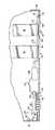
図3および図4を参照すると、連結機構50はスライドボタン40とともにロック位置とロック解除位置の間を移動する。連結機構50は、複数のアーム54、56、58を備えたロッド52を含む。1つのアーム54は、ディスプレイラッチ開口60に延びる。その他のアーム56、58は、カバー62、64、または開口22、24内に配置されたモジュラユニット26、28の取り外しを阻止、制限、または防止するためのその他の拡張部を含む。カバー62、64はアーム56、58に固定される。アーム56、58はロッド52に固定される。したがって、ロッド52が滑動するにつれて、アーム56、58およびカバー62、64はロッド52とともに移動する。このロッドは、スライドボタン40のロック位置44に対応する第1「ロック」位置66(図3参照)、およびスライドボタン40のロック解除位置42に対応する第2「ロック解除」位置68(図4参照)という2つの位置をとる。ロッドが第1ロック位置66にあるとき、カバー62、64は、モジュラユニット26、28の取り外しを阻止、制限、または防止する。ロッドが第2ロック解除位置68にあるとき、カバー62、64はモジュラユニット26、28の挿入/除去経路から外れている。カバーがモジュラユニットの挿入/除去経路をさえぎらないように、モジュラユニット26、28を取り付けまたは取り外しすることができる。
【0022】
図3および図4の実施形態では、ロッド52が第1ロック位置66または第2ロック解除位置68のどちらにある間も、カバー62、64はキーボードハウジング20の前面32から見える。代替の実施形態では、カバー62、64は、開口22、24を封鎖している間(すなわちロッドが第1ロック位置66にある間)のみ見える。このような代替の実施形態では、カバー62、64またはこれらのカバーの大部分は、ロッド52が第2ロック解除位置68に移動する際に、キーボードハウジング20の壁面の裏側に滑り込み、はっきり見えなくなる。
【0023】
図3および図4は、スライドボタン40とロッド52の機械的接続を有する連結機構50を示す図であるが、スライドボタン40が電気スイッチ46に結合され、このスイッチがソレノイド48を介して遠隔操作でロッド52を作動させる代替の実施形態を図14に示す。ソレノイド48はワイヤ47を介して電気スイッチ46に結合されるように示してあるが、この接続は赤外線などの無線手段を介して実現することもできる。この実施形態では、連結機構50は、依然として鎖錠器30に結合されているものと考えられるが、この結合は、少なくとも部分的には電気的に得られる。連結機構50は電磁式や圧電式などのさらに別の形態をとることができ、その場合でも依然として鎖錠器30に結合され、本発明の範囲内にあることが可能であることを、当業者は理解するであろう。
【0024】
図5は、カバー62、64の代わりに、拡張部70、72がアーム56、58に固定された別の代替の実施形態を示す図である。各モジュラユニット26、28は、隣接する壁面76を備えたノッチまたは凹領域74を含む。ロッド52が第1ロック位置66に移動する際に、拡張部70、72は壁面76に隣接するノッチまたは凹領域74の中に移動し、モジュラユニット26、28の取り外しを阻止、制限または防止する。各拡張部70、72と壁面76との相対位置により、対応するモジュラユニット26、28が開口22、24を介して除去または挿入されるのを阻止、制限、または防止する。別の実施形態では、アーム56、58は拡張部70、72を含まない。このような実施形態では、アーム56、58がノッチまたは凹領域74の中に移動し、壁面76に対して阻止、制限、または防止する関係になる。さらに別の実施形態では、ロッド52は、滑動せずに第1位置と第2位置の間で回転し、アーム56、58、拡張部70、72、またはカバー62、64を、阻止、制限、または防止する位置に移動させるか、またはその位置から外す。本発明の代替の実施形態によれば、ノッチまたは凹領域74は、モジュラユニット26、28の側面および縁部に、またはそこから離れて(たとえば面沿い、各縁部の間、モジュールの中央に)存在する。
【0025】
図3、図4、図6、および図7を参照し、次にアーム54の機能について説明する。アーム54はディスプレイラッチ82(図1参照)を固定し、これがキーボードハウジング20からラッチ解除するのを防止する。ディスプレイラッチ82は、ディスプレイハウジング18上に位置し、可動可動フック部84を含む。キーボードハウジング20はディスプレイラッチ82を受けるディスプレイラッチ開口60を含む。ディスプレイラッチ開口60は、止め構造86と一部で境界を接している。一実施形態では、ラッチの可動可動フック部84は、拡張位置と引込み位置の間で回転する。可動可動フック部84は、拡張位置に向かってバイアスが加えられ、かつ拡張位置を越えて回転しないように制限されている(図6(a)参照)。
【0026】
ディスプレイハウジング18が閉じてキーボードハウジング20と接すると、可動可動フック部84は止め構造86に突き当たる。ディスプレイハウジングがさらに閉じると、ディスプレイに加わる力が止め構造86から可動可動フック部84に及び、可動可動フック部84を引込み位置まで回転させる(図6(b)参照)。ディスプレイハウジングがさらに閉じると、可動可動フック部84は最終的に止め構造86を通過する。その後、ディスプレイラッチ82内の内部バイアスにより、可動可動フック部84は回転して拡張位置に戻る(図6(c)参照)。このとき、ディスプレイハウジング18は、キーボードハウジング20に閉じている。図6(d)は、定位置にロックされたディスプレイラッチ82を示す図である。本発明の一態様によれば、ロッドが第1(すなわちロック)位置66の中に移動したとき(図3および図6(d)参照)、アーム54の拡張部80は、ディスプレイラッチ開口60のディスプレイラッチ82の隣に移動する。拡張部80がディスプレイラッチ開口60の中にある間、ディスプレイを開くことはできない。拡張部がディスプレイラッチ開口60の中にない間は、ディスプレイを開くことができる。
【0027】
ロッド52が第2ロック解除位置68にある間にディスプレイを開く場合は、ユーザは、ディスプレイハウジング18にあるラッチボタン88を移動させる。ラッチボタン88はラッチ82を止め構造86から横向きに遠ざけて、可動可動フック部84が止め構造86を通過することができるようにし、ディスプレイハウジング18がキーボードハウジング20に対して自由に開くようにする。ロッド52が第1ロック位置66にある場合は、止め構造86を通過するためにディスプレイラッチ82が移動するはずの領域を、アーム54の拡張部80が塞いでいる。したがって、ロッドが第1ロック位置66にある間、ディスプレイラッチ82は封鎖され、ディスプレイは開かないようになる。
【0028】
いくつかの実施形態では、ディスプレイラッチ82の可動可動フック部84は、ディスプレイラッチ82の残りの部分に対して動かない一体化部分である。ディスプレイが閉じるにつれて、閉じる力は止め構造86を介して可動可動フック部84に加えられる。この力によって、ディスプレイラッチ82およびラッチボタン88は、可動フック部84の経路を止め構造86から遠ざけるように移動する。ディスプレイが十分に閉じたとき、可動フック部84は止め構造86を通過し、止め構造86とディスプレイラッチ82/可動フック部84の間の力はなくなる。その結果、ディスプレイラッチ82はその弛緩位置に移動する。閉じた状態の弛緩位置(図6(c)参照)では、止め構造86は、可動フック部84が垂直方向に引き抜かれるのを阻止する。可動フック部84を自由にし、ディスプレイを開くことができるようにするためには、ユーザは、手動でラッチボタン88を移動させなければならない。
【0029】
可動可動フック部84を備えたディスプレイラッチ82を有することの利点の1つは、連結機構50が第1ロック位置66にある時でも、ディスプレイを閉じることができる点である。図7(a)を参照すると、キーボードハウジング20のディスプレイラッチ開口60は、ディスプレイが開き、連結機構50がロック位置にある間、アーム54の拡張部80で部分的に塞がれている。ディスプレイが閉じるにつれて、ディスプレイラッチ82はディスプレイラッチ開口60の残りの部分にはまり込む。そのために、可動フック部84は引込み位置まで回転する。厳密にいえば、ディスプレイに加わる閉じる力が、可動フック部84と止め構造86の間の接触により、可動フック部84に移る(図7(b)参照)。ディスプレイが十分に閉じた後は、可動フック部84は止め構造86を通過し、可動フック部84はその拡張し、バイアスされた弛緩位置に戻る(図7(c)参照)。
【0030】
ディスプレイハウジング18がキーボードハウジング20に閉じ、連結機構50が第1ロック位置66にある状態では、アーム54の拡張部80が封鎖するように存在するので、ラッチボタン88を移動させてディスプレイを開くことはできない。
【0031】
再び図3および図4を参照すると、連結機構50はまた、ばね90およびスライドボタン40も含む。ばね90は、一端がキーボードハウジング20に固定され、反対側の一端がロッド52の端部に固定される。スライドボタン40はロッド52に結合され、ロッド52をスライドボタン40とともに移動させる、また逆にスライドボタン40をロッド52とともに移動させるようになっている。ばね90は、第2ロック解除位置68に向かってロッドに力を加える(図4参照)。したがって、鎖錠器30が開く、すなわちロック解除されるとき、ロッド52はばね90の力によって第2ロック解除位置68に移動する。広義には、鎖錠器30で正しい組合せが入力された時、ばね90は、連結機構50を自動的に第2ロック解除位置68に移動させる。
【0032】
スライドボタン40がロック解除位置42からロック位置44まで移動するとき、ロッド52は、スライドボタン40とともにその第1ロック位置66に移動する。いくつかの実施形態では、スライドボタン40(またはロッド52)が移動することによりタンブラ34〜37が移動し、その結果鎖錠器30がロック状態になる。
【0033】
(構成部品のディスエーブル)
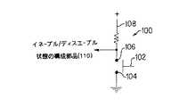
図8は、スライドボタン40の位置に応答するイネーブル/ディスエーブル回路100の電気的概略図である。イネーブル/ディスエーブル回路100は、接地された1つの端子104と、電源信号108、およびイネーブル/ディスエーブル状態の構成部品110に結合されたもう1つの端子106とを有するスイッチ102を含む。スイッチ102は、第1状態または第2状態のどちらかに位置決めされる。スライドボタン40がロック位置44に移動すると、スイッチ102は第1状態になる。スライドボタン40がロック解除位置42に移動すると、スイッチ102は第2状態になる。図示する実施形態では、第1状態はスイッチが閉じた状態に相当し、第2状態はスイッチが開いた状態に相当する。閉じているとき、電源信号108は地面に流れ、それにより所望の構成部品110をディスエーブルする。開いているとき、電源信号108は所望の構成部品110に流れ、それによりその構成部品をイネーブルにする。
【0034】
本発明の一態様によれば、イネーブル/ディスエーブル回路100は、構成部品であるキーボード14への電源信号経路に位置するが、別の同様のイネーブル/ディスエーブル回路100は所望の各入力装置112(例えば一体式のマウス、タッチパッド、消去ヘッド、トラックボールや、外付けのマウス、タッチパッド、トラックボールや、その他の一体式または外付けの指示装置およびクリック装置)への電源信号経路に位置する。さらに、マザーボード、処理装置、I/Oポート、ローカルバス、ビデオバス、拡張バス、周辺装置など、その他の1つまたは複数の構成部品は、所望の構成に応じて、同様にディスエーブルされ、イネーブルにされる。好ましい実施形態によれば、キーボード、指示装置、およびクリック装置は、スライドボタン40の位置にしたがってイネーブルにされ、ディスエーブルされる。代替実施形態では、スライドボタン40が移動すると、その代わりにCPU218の割込みが引き起こされる。その後、CPU218は、この割込みを処理し、1つまたは複数の入力装置、バス、ポート、モジュラユニット、構成部品、または装置をディスエーブルする。
【0035】
本発明の別の態様によれば、ユーザには、スライドボタン40が第1ロック位置66にある間、いくつかの構成部品をディスエーブルするかどうかを選択する権利が与えられる。図9は、このような選択権がユーザに与えられている構成部品とともに使用される回路116を示す図である。回路116はイネーブル/ディスエーブル回路100と同じものであるが、スイッチ112を活動状態にするかどうかを決定する追加のスイッチ118を含む。スイッチ118は、スイッチ112と直列(図9に示す)に、またはスイッチ112と並列に位置する。その他の実施形態では、スイッチ118はその代わりに任意選択の構成部品120と直列または並列に、あるいは電源と直列に位置する。
【0036】
さらに別の実施形態では、スイッチ112、118の代わりに複数位置スイッチを使用する。ユーザは、ソフトウェアの制御下で、スイッチ118の位置を制御する。回路116は、任意選択で制御される各構成部品120への電源信号経路に位置する。ユーザが構成部品120をディスエーブルすることを選択すると、スイッチ118が閉じる。そうでない場合にはスイッチ118は開いたままである。スイッチ118が閉じると、スイッチ112で、構成部品120をイネーブルにするかまたはディスエーブルするかを決定することができる。スイッチ118が開いているときは、スイッチ112の位置とは無関係に、構成部品120はイネーブルになる。結果として、回路116がスイッチ118を閉じるように構成され、スライドボタン40がスイッチ112を閉じる場合にのみ、構成部品120はディスエーブルされる。好ましい実施形態によれば、ユーザには、システムのオン/オフスイッチ114(図1参照)の信号経路に回路116を配置することによって、このオン/オフスイッチをスライドボタン40の状態に結合するというオプションが与えられる。その他の構成によれば、回路116は、マザーボード、処理装置、I/Oポート、ローカルバス、ビデオバス、拡張バス、または周辺装置などの、1つまたは複数の他の構成部品の電源信号の経路に含まれる。
【0037】
(ドッキング解除能力のディスエーブル)
図10を参照すると、構成部品であるドッキングステーション121内に挿入されたノートブックコンピュータ10を示す。ドッキングステーション121の機能は、追加の周辺装置へのアクセスを提供すること、およびデスクトップ環境におけるノートブックコンピュータシステムの有用性を高めることである。ノートブックコンピュータはサイズが小型であるので、望ましい全ての周辺装置をシステムに備え付けるだけの、十分なスペースがないことがしばしばある。ドッキングステーションは、フロッピーディスクドライブやCD−ROMドライブなどの追加の周辺装置へのアクセスを提供する。有用性を高めるために、ドッキングステーションは、外部のキーボードおよびディスプレイモニタを接続するポートを備える。ノートブックコンピュータ10に一体化されたフラットパネルディスプレイ12およびキーボード14は、通常は運搬性を促進するために小型であるので、外部のキーボードおよびモニタとともにノートブックコンピュータを使用することが、時には望ましい。ユーザがノートブックコンピュータを動かすたびにケーブルを交換するのではなく、ドッキングステーションは、モニタおよびキーボードへの常に一定の接続を提供する。単にノートブックコンピュータ10をドッキングステーション121に挿入するだけで、ノートブックコンピュータと外部のキーボード、ディスプレイ、および1つまたは複数の周辺装置との接続が確立される。
【0038】
ドッキングステーション121は排出ボタン122を含む。この排出ボタン122を押すと、ノートブックコンピュータはドッキングステーション121から排出される。図11を参照すると、ドッキングステーションはまた、ノートブックコンピュータのキーボードハウジング20のくぼみ126に対合する1つまたは複数のラッチ124も含む。排出ボタン122を押すと、ラッチ124がくぼみ126から解除され、アクチュエータがノートブックコンピュータをドッキングステーション121から外側へ押し出す。一実施形態では、このアクチュエータは、ラッチ124の作動と、ノートブックコンピュータ10の排出とを両方とも行う。ラッチ124がくぼみ126に対合している間、ユーザは、ドッキングステーション121からノートブックコンピュータを取り外すことができない。
【0039】
本発明の一態様によれば、ノートブックコンピュータのスライドボタン40がロック位置44にある間、排出ボタン122はディスエーブルされている。図12は、ノートブックコンピュータ10を排出するための回路130、131を示す図である。回路130はドッキングステーション121内に位置する。回路131はノートブックコンピュータ10内に位置する。回路130は、ドッキングステーション121側の接点138、140、およびノートブックコンピュータ10側の接点142、144を介して、回路131と結合する。接点138〜144は、ノートブックコンピュータ10とドッキングステーション121の間のピン接続によって形成される。一実施形態では、このピン接続は、ノートブックコンピュータとドッキングステーションとの間の信号交換用に使用される、複数ピンコネクタの一部である。別の実施形態では、ピン接続による接点138〜144は、ノートブックコンピュータとドッキングステーション121との間の電気接続を揃えるために使用されるガイドピンに取って代わるか、またはこれらに追加される。
【0040】
回路130は、スイッチ132およびアクチュエータ134を含む。スイッチ132は、電源信号に結合される。スイッチ132が閉じると、電源信号がアクチュエータ134に送られる。回路130が(回路131を介して)閉じると、信号経路146は接地され、アクチュエータ134に電圧が加わり、ノートブックコンピュータ10が排出される。回路130が(例えば回路131で)開いたままのときは、アクチュエータは活動状態にはならず、ノートブックコンピュータははじき出されない。
【0041】
回路131は、ノートブックコンピュータ10内にスイッチ150を含む。このスイッチ150の状態は、スライドボタン40の位置によって規定される。スライドボタン40がロック解除位置42にあるときは、スイッチ150は閉じている。スライドボタン40がロック位置44にあるときは、スイッチ150は開いている。最初に、スライドボタンがロック解除位置42にあり、したがってスイッチ150が閉じている状態を考慮されたい。ユーザが排出ボタン122を押すと、スイッチ132が閉じ、電流が、電源からアクチュエータ134に流れ、信号経路146に沿って接点138、142を越え、閉じたスイッチ150を通過して接点144、140を越えて、その後地面へと流れる。回路130、131が閉じることにより、アクチュエータ134はノートブックコンピュータ10を解除し、排出することができる。
【0042】
次に、スライドボタン40がロック位置44にあり、したがってスイッチ150が開いている状態を考慮されたい。ユーザが排出ボタン122を押すと、スイッチ132が閉じ、電流が、電源からアクチュエータ134に流れ、信号経路146に沿って接点138、142を越える。しかし、ノートブックコンピュータのスイッチ150が開いているので、回路131は開き、電流の戻り経路が存在しない。したがって、回路130もまた開いたままになり、アクチュエータは活動状態にならない。その結果、アクチュエータおよび排出ボタンはディスエーブルになる。
【0043】
(ノートブックコンピュータのアーキテクチャ)
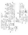
図13は、複数の周辺装置とともに動作するように構成されたノートブックコンピュータ10のシステムアーキテクチャを示す。ノートブックコンピュータ10は、CPU218、システムメモリ(例えば224、250)、複数の通信バス252、254、256、258、ならびにいくつかのシステムの構成部品および周辺装置を含む。通信バス、ならびにシステムの構成部品および周辺装置の数およびタイプは、実施形態が異なれば変化する。図示したノートブックコンピュータ10の場合は、プロセッサバス252、ローカルバス254、I/Oバス256、および拡張バス258がある。CPU218、外部キャッシュ250、およびシステムRAM224は、プロセッサバス252上に位置する。I/Oバス256はプロセッサバス252に連結され、I/Oポートへのインターフェースをとる。プリンタ266、指示装置220、およびクリック装置222(例えばマウス)は、通常はI/Oバス256に結合される。
【0044】
ローカルバス254は、ローカルバスインターフェース270を介してプロセッサバス252に連結される。ローカルバスの例としては、ビデオローカル(VL)すなわちVESA標準バス、周辺構成部品インターフェース(PCI)バス、およびNU−BUSがある。例えば、PCIバスは、周辺装置を10個まで結合することができる。図示したのは、グラフィックスコントローラ272、ビデオプロセッサ274、赤外線デジタル通信インターフェース276、および音声カード278である。スピーカ280およびマイクロフォン282は音声カード278に連結される。ビデオサブシステムであるグラフィックスコントローラ272、ビデオプロセッサ274は、通常はローカルメモリ資源である共用メモリ(すなわちフレームバッファまたはビデオRAM)290を共有する。情報は、ビデオサブシステムおよび共有される共用メモリ290からビデオDAC294を介してフラットパネルディスプレイ12に移る。
【0045】
拡張バス258は、ローカルバス254および拡張バスインターフェース296を介して、プロセッサバス252に連結される。周辺装置、システム構成部品、および大容量記憶装置は、通常は拡張バス258に結合される。示したのは、ハードディスクドライブ(HDDまたは大容量記憶装置)26およびフロッピーディスクドライブ(FDD)202に結合するドライブコントローラ298、光学記憶装置210またはその他のSCSI周辺装置に結合するSCSIコントローラ208、ならびにファックス/モデム28である。SCSIコントローラ208の代替として、いくつかのメーカー独自のコントローラもまた、光学記憶装置210に結合することができる。その他のアーキテクチャによれば、ハードディスクドライブ26および/または光学記憶装置210(例えばCD−ROM)、およびそれらのそれぞれのコントローラは、その代わりにローカルバス254に結合される。
【0046】
示したアーキテクチャは例示的なアーキテクチャである。ノートブックコンピュータ10は、パーソナルコンピュータ、PENTIUMコンピュータ、APPLE MACINTOSHコンピュータ、あるいは現在入手可能であるか、またはIntel80X86アーキテクチャ、Motorola68XXXアーキテクチャ、PowerPCアーキテクチャ、もしくはその他のCISCプロセッサアーキテクチャ、RISCプロセッサアーキテクチャ、およびその他の単一または複数の多重プロセッサアーキテクチャに基づくその他のコンピュータ用の、所有権のあるまたは公開のアーキテクチャを実施したものである。別法として、ノートブックコンピュータ10は、ハンドヘルドコンピュータ装置またはINTERNET通信装置用のより単純なアーキテクチャを具体化する。
【0047】
(有益かつ有利な効果)
ノートブックコンピュータ10は、スライドボタン40がロック位置44にあり、したがって連結機構50が第1ロック位置66にあるときに規定される、ロック状態を有する。ロック状態にある間、モジュラユニット(例えばバッテリ、ハードディスクドライブ、フロッピーディスクドライブ、PCカード)は、キーボードハウジング20の開口または間口(例えば開口22、24)にロックされる。さらに、キーボード、指示装置およびクリック装置を介した入力はディスエーブルされ、ノートブックコンピュータ10は、ドッキングしている場合は、ドッキング解除しないようになっている。ディスプレイハウジング18がキーボードハウジング20に閉じている場合は、ディスプレイハウジング18もまた定位置にロックされ、再び開かないようになる。最後に、ユーザが機密保護システムに組み込むように選択した任意選択の任意の機構が活動化される(例えばオン/オフスイッチがディスエーブルされる)。好ましい構成では、ユーザは依然として、電子メールの受信、ファックスの待機、またはデータ同期化の実行などの無人動作を、ドッキングポートを介して実行させておくことができる。ノートブックコンピュータ10は、スライドボタン40がロック解除位置42にあり、したがって連結機構50が第2ロック解除位置68にあるときに規定される、ロック解除状態を有する。ロック解除状態にある間、機密保護措置は停止する(例えばクラムシェルをロック解除し、周辺ユニットをロック解除し、キーボードおよびマウスをイネーブルにし、ドッキング解除をイネーブルにする)。
【0048】
本発明の好ましい実施形態について、図示および説明したが、さまざまな代替のもの、修正したもの、および同等のものを使用することができる。したがって、前述の説明は、特許請求の範囲によって定義される本発明の範囲を制限するものではないと見なされたい。
【0049】
以下に本発明の実施の形態を要約する。
1. ケース(16)とディスプレイ(12)と入力装置(14、112)と処理装置(218)とモジュラユニット(26)と鎖錠器(30)と連結機構(50)とを具備し、 前記ケースが開口(22)を規定し、前記モジュラユニットが前記開口内に脱着可能に挿入され、
前記連結機構が前記鎖錠器に結合され、前記連結機構が第1位置(44)と第2位置(42)との間を移動可能であり、前記連結機構が前記第1位置にある間は前記モジュラユニットの取り外しを防止し、
前記鎖錠器がロック状態を規定している間、前記連結機構が前記第2位置に移動しないようにされているポータブルコンピュータ装置(10)。
【0050】
2. 前記ケースが、内部に前記ディスプレイが取り付けられた第1ハウジング(18)と、
内部に前記モジュラユニットが脱着可能に挿入される前記開口を規定し、内部に前記入力装置、前記処理装置、および前記モジュラユニットが取り付けられる第2ハウジング(20)とを具備し、
前記第1ハウジングが、前記ディスプレイパネルを見ることができる開いた位置と格納するための閉じた位置との間で、前記第2ハウジングに対して移動し、
連結機構が、前記第2ハウジング内に取り付けられ、前記第1ハウジングが閉じた位置にあり、かつ前記連結機構が前記第1位置にあるときに、前記第1ハウジングが前記第2ハウジングに対して開くのを防止する上記1記載のポータブルコンピュータ装置。
【0051】
3. 前記鎖錠器がロック解除状態に切り替わったときに、前記連結機構が自動的に前記第2位置に移動する上記1または2に記載のポータブルコンピュータ装置。
【0052】
4. 前記連結機構が前記第1位置にある間、前記ポータブルコンピュータ装置の動作を制限する回路(100)をさらに含む上記1〜3のいずれかに記載のポータブルコンピュータ装置。
【0053】
5. 前記コンピュータ装置がドッキングステーション(120)からドッキング解除されるのを妨げる第1状態と、前記コンピュータ装置が前記ドッキングステーションからドッキング解除されるのを妨げない第2状態とを有する回路(131)をさらに含み、前記回路が、前記連結機構が前記第1位置にある間は前記第1状態にあり、前記連結機構が前記第2位置にある間は前記第2状態にある上記1〜4のいずれかに記載のポータブルコンピュータ装置。
【0054】
6. 前記連結機構が、スイッチの第1位置およびスイッチの第2位置を規定するスイッチ(40)と、前記連結機構の前記第1位置と前記連結機構の前記第2位置との間を移動するリンク(52)とを具備し、さらに、前記連結機構が前記第1位置にある間前記モジュラユニットの取り外しを制限する、前記リンクに対して固定された第1部材(62)と、前記第1ハウジングが前記第2ハウジングに対して前記閉じた位置にあり、かつ前記連結機構が前記第1位置にある間、前記第1ハウジングの前記閉じた位置からの移動を制限する、前記リンクに対して固定された第2部材(80)とを具備し、前記リンクの第1位置が前記スイッチの第1位置と一致し、前記リンクの第2位置が前記スイッチの第2位置と一致する上記1〜5のいずれかに記載のポータブルコンピュータ装置。
【0055】
7. ケース(16)と鎖錠器(30)と連結機構(50)と回路(100)とを具備し、入力装置(14)と処理装置(218)とモジュラユニット(26)と鎖錠器(30)と連結機構(50)とが前記ケース内に取り付けられ、前記ケースが開口(22)を規定し、前記開口内に前記モジュラユニットが脱着可能に挿入され、前記鎖錠器が所与の時間においてロック状態またはロック解除状態のどちらか一方を規定し、前記連結機構が前記鎖錠器に結合され、第1位置(44)と第2位置(42)の間で移動可能であり、前記回路が第1状態および第2状態を有するポータブルコンピュータ装置(10)へのアクセスを機密保護するための方法において、
第1動作が前記ロック状態を規定するために前記鎖錠器を切り替え、
前記鎖錠器が前記ロック状態を規定している間、前記連結機構が前記第2位置に移動するのを防止されている、
前記第1動作を介して前記コンピュータ装置に対する前記ロック状態を、前記連結機構を前記第1位置に移動させ、前記連結機構が前記モジュラユニットの取り外しを制限し、前記回路を前記コンピュータ装置の構成部品の動作がディスエーブルされる前記第1状態にすることによって規定し、
前記鎖錠器を前記ロック解除状態に切り替える動作を含む第2動作を介して、
前記コンピュータ装置に対する前記ロック解除状態を、前記モジュラユニットの取り外しを制限しない前記第2位置に前記連結機構を移動させ、前記回路を前記構成部品をディスエーブルしない前記第2状態にすることによって規定する方法である。
【0056】
8. 前記ケースが、第1ハウジング(18)および第2ハウジング(20)を含み、前記第1ハウジングが前記開いた位置と閉じた位置との間で前記第2ハウジングに対して移動し、前記連結機構が前記第1位置にあり、かつ前記第1ハウジングが前記閉じた位置にある間、前記連結機構が、前記第1ハウジングが前記開いた位置に移動するのを防止する上記7記載の方法。
【0057】
9. 前記回路が第1の回路であり、前記コンピュータ装置がさらに第2の回路(131)を含み、前記回路が、前記コンピュータ装置がドッキングステーションからドッキング解除されないようになっている第1状態、および前記コンピュータ装置が前記ドッキングステーションからドッキング解除されるのを妨げない第2状態を有し、前記連結機構が前記第1位置にある間は前記第1状態にあり、前記連結機構が前記第2位置にある間は前記第2状態にあり、また、前記ロック状態を規定するステップが、前記第2の回路を前記第1状態にするステップをさらに含み、前記ロック解除状態を規定するステップが、前記第2の回路を前記第2状態にするステップをさらに含む上記7または8記載の方法。
【0058】
10. 前記回路が第1の回路であり、前記構成部品が第1構成部品であり、前記コンピュータ装置が、第1状態および第2状態を有する第3回路(116)を含み、前記第3回路をイネーブルにするか、またはディスエーブルするか、どちらか一方を行うように前記コンピュータ装置を構成する方法において、
前記規定するステップが、前記第3回路がイネーブルにされたときに前記第3回路を前記第1状態にし、前記第3回路が前記第1状態にある間、第2構成部品がディスエーブルされる上記7〜9のいずれかに記載の方法。
【0059】
【発明の効果】
本発明の1つの利点は、単一の動作を実行するだけで、コンピュータがロック状態またはロック解除状態に切り替わる点である。もう1つの利点は、機密保護措置が活動状態にある間にも、ユーザが依然として無人機能を実行させることができる点である。もう1つの利点は、ユーザが何らかの機密保護措置を、その機密保護システムを使用してディスエーブルする(すなわちコンピュータをロック状態にする)任意選択の構成部品を選択できるように構成することができる点である。
【図面の簡単な説明】
【図1】本発明の一実施形態による物理的機密保護システムを備えたノートブックコンピュータの透視投影図である。
【図2】モジュラユニットが取り付けられロック状態にあるノートブックコンピュータの部分的透視投影図である
【図3】本発明の一実施形態による、ロック位置にある連結機構を示すコンピュータの部分的平面切開図である。
【図4】本発明の一実施形態による、ロック解除位置にある連結機構を示すコンピュータの部分的平面切開図である。
【図5】本発明の代替実施形態による、モジュラユニットに作用する連結機構のロッド部およびアーム部を示す図である。
【図6】本発明の一実施形態による、ディスプレイハウジングのラッチとキーボードハウジングの止め構造の間の動作を示す図である。
【図7】本発明の代替実施形態による、ディスプレイハウジングのラッチとキーボードハウジングの止め構造の間の動作を示す図である。
【図8】所望のシステム構成部品へのアクセスをイネーブル/ディスエーブルする回路の概略図である。
【図9】所望のシステム構成部品へのアクセスを任意選択でイネーブル/ディスエーブルする回路の概略図である。
【図10】ドッキングステーションに挿入されたノートブックコンピュータの透視投影図である。
【図11】ノートブックコンピュータをドッキングステーションに固定するラッチ接続を示す図である。
【図12】本発明の一実施形態による、ノートブックコンピュータのドッキングステーションからの排出を制御する回路を示す概略図である。
【図13】例示的なノートブックコンピュータのアーキテクチャを示すブロック図である。
【図14】本発明の代替実施形態による、ロック解除位置にある連結機構を示すコンピュータの部分的平面切開図である。
【符号の説明】
10 ノートブックコンピュータ
18 ディスプレイハウジング
20 キーボードハウジング
22、24 開口
30 鎖錠器
40 スライドボタン
60 ディスプレイラッチ開口
82 ディスプレイラッチ[0001]
BACKGROUND OF THE INVENTION
The present invention relates to a portable computer, and more particularly to a technique for securing access to a portable computer.
[0002]
[Prior art]
There are many types of general purpose and special purpose computers used in various computer applications. Personal computers and computer workstations are among several different processors (eg 80386, 80486, 586, PENTIUM ™, PowerPC ™, Alpha) and operating systems (eg DOS, Windows 95, Windows NT, UNIX, MAC-OS, OS / 2). A general computer system architecture that can be utilized in many different configurations with any of the following: Various types classified by case size include desktop computers, laptop computers, notebook computers, and palmtop or handheld computers. Laptops, notebooks, and palmtop or handheld computers are also referred to as portable computers.
[0003]
A portable computer is a general configuration that can improve the mobility of a user. Usually, the processor board, display, and keyboard are integrated into a common case. A notebook computer case typically includes a display housing and a keyboard housing that are permanently attached to each other in a hinged manner. The flat panel display is mounted within the display housing. A keyboard, motherboard, data storage unit, expansion slot, and I / O port are mounted within the keyboard housing. Modular peripheral units such as floppy disk drives, hard disk drives, CD-ROM drives, and modems, or other PC cards are easily attached to and removed from this case. The size of a conventional notebook computer is approximately the size of a standard sheet of paper (for example, 21.6 x 27.9 cm, or 8.5 x 11.0 inches in English) and weighs less than 6 pounds It is. The thickness of such a notebook computer is typically 4.5 cm to 6.0 cm. Notebook computers can be easily transported due to their small size and light weight and their integrated nature. However, these characteristics have also made this computer and its modular unit a target that can be easily stolen. Therefore, there is a need to prevent theft of portable computers and their modular units.
[0004]
[Problems to be solved by the invention]
Individuals, businesses, and facilities are increasingly relying on portable computers to perform a variety of tasks. This computer often serves as a data input terminal, communication device, information storage center, and / or information processing center. The information stored on each computer often exceeds the value of the computer itself. Accordingly, there is a need to prevent unauthorized access to portable computers and their stored data.
[0005]
[Means for Solving the Problems]
The present invention is directed to physical security measures that limit access to a portable computer and its modular units, devices, and components. In accordance with the present invention, the portable computer includes a physical security device that locks the display and system unit together (eg, in the form of a “clamshell”). This security device also prevents removal of peripheral devices and disables input from a computer keyboard and mouse. In some modes of operation, the security device also prevents an increase in computer energy consumption and removal of the computer from the docking station.
[0006]
According to one aspect of the invention, the computer is placed in either a locked or unlocked state. In the locked state, the peripheral device is locked in the computer case and the keyboard and mouse are disabled. When the computer case closes, it will not open again.
[0007]
According to another aspect of the present invention, the coupling mechanism moves between a locked position that defines a locked state and an unlocked position that defines a unlocked state. A key lock or combination lock (eg, tumbler, keypad) locks the coupling mechanism in the locked position. The user unlocks the key lock or combination lock and moves the coupling mechanism from the locked position to the unlocked position. In some embodiments, the coupling mechanism automatically moves to the unlocked position upon turning the key or entering the correct combination. Conversely, when the user moves the coupling mechanism from the unlocked position to the locked position, the lock or combination lock of some embodiments automatically locks. One advantage of this security system is that it performs a single action (for example, moving the coupling mechanism to the locked position) to lock the clamshell, lock the peripheral units in place, and disconnect the keyboard and mouse. It is a point that will be enabled. Similarly, performing a single action (eg, unlocking a lock or combination lock) will stop security measures (eg, unlocking the clamshell, Unlock and enable keyboard and mouse).
[0008]
According to another aspect of the present invention, when the computer is locked while the power is on, the user can still access each port (excluding the mouse port). Thus, the user can cause the computer to perform unattended functions such as searching for electronic mail, performing automatic backup, and waiting for fax transmission. Unaffected external communication occurs through a LAN connection, modem connection, docking connection, or other port connection.
[0009]
In accordance with another aspect of the present invention, the user can leave the system on / off button functioning normally while the computer is locked, or disable the on / off button. Can be specified. If left functioning normally, the user can turn on the power and enable external communication over a LAN connection, modem connection, docking connection, or other port connection.
[0010]
In accordance with another aspect of the invention, the portable computer is not unlocked from the docking unit while in the locked state.
[0011]
According to a preferred embodiment, the portable computer includes a first housing, a second housing, a lock device, and a coupling mechanism. The display panel is attached to the first housing. The keyboard, processing unit, and modular unit are attached to the second housing. In a preferred embodiment, a lock and a coupling mechanism are also attached to the second housing. The second housing defines an opening. The modular unit is detachably inserted into this opening. The first housing moves relative to the second housing between an open position for viewing the display panel and a closed position where the display panel is held by the second housing. The lock device defines either the locked state or the unlocked state at a predetermined time. The coupling mechanism is coupled to the lock device. The coupling mechanism moves between the first position and the second position. The coupling mechanism prevents or restricts removal of the modular unit while in the first position, otherwise it prevents it. The coupling mechanism also prevents the first housing from opening relative to the second housing when the first housing is in the closed position and the coupling mechanism is in the first position. The coupling mechanism does not move to the second position while the lock device defines the locked state. The coupling mechanism automatically moves to the second position when the lock is switched to the unlocked state.
[0012]
The computer device also includes an input device for a user to enter commands into the computer device, and a first circuit for disabling the keyboard and input device while the coupling mechanism is in the first position. The first circuit enables the keyboard and input device while the coupling mechanism is in the second position. The second circuit optionally disables a component (eg, an on / off switch) of the computer device while the coupling mechanism is in the first position. The third circuit has a first state that prevents the computer device from being unlocked from the docking station and a second state that does not prevent the computer device from being unlocked from the docking station. The third circuit is in the first state while the coupling mechanism is in the first position, and is in the second state while the coupling mechanism is in the second position.
[0013]
The coupling mechanism includes a slide button and a link. The slide button defines a first position of the switch and a second position of the switch. The link moves between a first position of the coupling mechanism and a second position of the coupling mechanism. The coupling mechanism also includes a first member secured to the link that prevents, restricts, or otherwise prevents removal of the modular unit while the coupling mechanism is in the first position. The second member fixed to the link prevents the first housing from moving from the closed position while the first housing is in the closed position with respect to the second housing and the coupling mechanism is in the first position. Or limit, otherwise prevent. The first position of the link coincides with the first position of the switch, and the second position of the link coincides with the second position of the switch.
[0014]
A method for securing access to a portable computer device includes the steps of defining a locked state for the computer device by moving the coupling mechanism to a first position, and locking the computer device by switching the lock to the unlocked state. Defining a release state. While in the first position, the coupling mechanism prevents or restricts removal of the modular unit, otherwise prevents the first housing from opening relative to the second housing when the first housing is in the closed position. To prevent. The first circuit switches to the first state when the coupling mechanism moves to the first position and disables the keyboard and input device. The coupling mechanism does not move to the second position while the lock device defines the locked state. While in the second position, the coupling mechanism does not prevent removal of the modular unit and does not prevent the first housing from opening relative to the second housing. The first circuit switches to the second state when the coupling mechanism moves to the second position. While in the second state, the first circuit no longer disables the keyboard and pointing device.
[0015]
Another step of the method includes configuring the computing device to either enable or disable the second circuit. The step of defining the lock state includes the step of bringing the second circuit into the first state when the second circuit is enabled. While the second circuit is in the first state, the on / off switch that activates the computing device is disabled.
[0016]
The third circuit has a first state that prevents the computer device from being undocked from the docking station and a second state that does not prevent the computer device from being undocked from the docking station. The third circuit is in the first state while the coupling mechanism is in the first position, and is in the second state while the coupling mechanism is in the second position. The step of defining the lock state includes the step of setting the third circuit to the first state. The step of defining the unlocked state includes the step of setting the third circuit to the second state.
[0017]
One advantage of the present invention is that the computer switches to a locked or unlocked state when a simple operation is performed (eg, moving the slide button or moving the slide button to set the lock) ). Another advantage is that the user can still perform unattended functions while the security measures are active. Another advantage is that the user can configure some security measures so that they can select optional components to be disabled by the security system (ie when the computer enters a locked state). It is. These and other aspects and advantages of the present invention will be better understood by reference to the following detailed description taken in conjunction with the accompanying drawings.
[0018]
DETAILED DESCRIPTION OF THE INVENTION
(Overview)
1 and 2 are diagrams showing a portable computer according to an embodiment of the present invention. A portable computer is a notebook computer, laptop computer, handheld computer, personal digital assistant, or other general purpose or special portable computing device. The portable computer includes a processing unit (not shown), a
[0019]
According to one aspect of the present invention, the
[0020]
In the preferred embodiment, the
[0021]
(Security protection connection mechanism)
3 and 4, the
[0022]
In the embodiment of FIGS. 3 and 4, the
[0023]
FIGS. 3 and 4 show a
[0024]
FIG. 5 shows another alternative embodiment in which
[0025]
Next, the function of the arm 54 will be described with reference to FIGS. 3, 4, 6 and 7. Arm 54 secures display latch 82 (see FIG. 1) and prevents it from unlatching from
[0026]
When the
[0027]
To open the display while the
[0028]
In some embodiments, the movable
[0029]
One advantage of having the
[0030]
When the
[0031]
Referring again to FIGS. 3 and 4, the
[0032]
When the
[0033]
(Disable component parts)
FIG. 8 is an electrical schematic diagram of the enable / disable
[0034]
According to one aspect of the present invention, the enable / disable
[0035]
In accordance with another aspect of the present invention, the user is given the right to choose whether to disable some components while the
[0036]
In yet another embodiment, multi-position switches are used in place of the switches 112,118. The user controls the position of
[0037]
(Disable undocking ability)
Referring to FIG. 10, the
[0038]
[0039]
According to one aspect of the present invention, the
[0040]
The
[0041]
The
[0042]
Next, consider the situation where the
[0043]
(Notebook computer architecture)
FIG. 13 illustrates the system architecture of the
[0044]
The
[0045]
The
[0046]
The architecture shown is an exemplary architecture. The
[0047]
(Beneficial and advantageous effects)
The
[0048]
While the preferred embodiment of the invention has been illustrated and described, various alternatives, modifications, and equivalents can be used. Therefore, the above description should not be taken as limiting the scope of the invention which is defined by the appended claims.
[0049]
Embodiments of the present invention are summarized below.
1. A case (16), a display (12), an input device (14, 112), a processing device (218), a modular unit (26), a lock device (30), and a coupling mechanism (50); Defining an opening (22), wherein the modular unit is removably inserted into the opening;
While the coupling mechanism is coupled to the lock, the coupling mechanism is movable between a first position (44) and a second position (42), while the coupling mechanism is in the first position. Preventing removal of the modular unit,
A portable computing device (10) wherein the coupling mechanism is prevented from moving to the second position while the lock is defining a locked state.
[0050]
2. The case includes a first housing (18) in which the display is mounted;
A second housing (20) in which the opening into which the modular unit is removably inserted is defined, and the input device, the processing device, and the modular unit are mounted;
The first housing moves relative to the second housing between an open position where the display panel can be viewed and a closed position for storage;
When the coupling mechanism is mounted in the second housing, the first housing is in the closed position, and the coupling mechanism is in the first position, the first housing is in relation to the second housing. 2. The portable computer device according to 1 above, which prevents opening.
[0051]
3. 3. The portable computer device according to 1 or 2 above, wherein the coupling mechanism automatically moves to the second position when the lock is switched to an unlocked state.
[0052]
4). 4. The portable computer device according to any one of claims 1 to 3, further comprising a circuit (100) that restricts the operation of the portable computer device while the coupling mechanism is in the first position.
[0053]
5. A circuit (131) having a first state that prevents the computer device from being undocked from the docking station (120) and a second state that does not prevent the computer device from being undocked from the docking station; Any one of the above 1 to 4, wherein the circuit is in the first state while the coupling mechanism is in the first position, and is in the second state while the coupling mechanism is in the second position. A portable computer device according to claim 1.
[0054]
6). The connection mechanism includes a switch (40) that defines a first position of the switch and a second position of the switch, and a link that moves between the first position of the connection mechanism and the second position of the connection mechanism ( 52) and a first member (62) fixed to the link for restricting removal of the modular unit while the coupling mechanism is in the first position, and the first housing Fixed to the link that is in the closed position relative to the second housing and restricts movement of the first housing from the closed position while the coupling mechanism is in the first position. A second member (80), wherein the first position of the link coincides with the first position of the switch, and the second position of the link coincides with the second position of the switch. Either Placing portable computer device.
[0055]
7). A case (16), a lock device (30), a coupling mechanism (50), and a circuit (100) are provided. An input device (14), a processing device (218), a modular unit (26), and a lock device (30 ) And a coupling mechanism (50) are mounted in the case, the case defines an opening (22), the modular unit is removably inserted into the opening, and the lock is provided for a given time. The locking mechanism is coupled to the lock and is movable between a first position (44) and a second position (42), In a method for securing access to a portable computing device (10) having a first state and a second state,
A first action switches the lock to define the locked state;
While the lock device defines the locked state, the coupling mechanism is prevented from moving to the second position,
Moving the coupling mechanism to the first position, the coupling mechanism restricts removal of the modular unit, and the circuit is a component of the computer apparatus via the first operation; Defining the first state in which the operation of is disabled,
Through a second operation including an operation of switching the lock to the unlocked state,
The unlocked state for the computer device is defined by moving the coupling mechanism to the second position that does not restrict removal of the modular unit, and placing the circuit in the second state without disabling the components. Is the method.
[0056]
8). The case includes a first housing (18) and a second housing (20), and the first housing moves relative to the second housing between the open position and the closed position, and the connection mechanism 8. The method of claim 7, wherein the coupling mechanism prevents the first housing from moving to the open position while is in the first position and the first housing is in the closed position.
[0057]
9. A first state in which the circuit is a first circuit, the computer device further includes a second circuit (131), wherein the circuit prevents the computer device from being undocked from a docking station; and A second state that does not prevent the computer device from being undocked from the docking station; the connection mechanism is in the first state while the connection mechanism is in the first position; and the connection mechanism is in the second position. It is in the second state for a while, and the step of defining the locked state further includes the step of bringing the second circuit into the first state, and the step of defining the unlocked state comprises the first state 9. The method according to claim 7 or 8, further comprising the step of bringing two circuits into the second state.
[0058]
10. The circuit is a first circuit, the component is a first component, and the computing device includes a third circuit (116) having a first state and a second state, and the third circuit is enabled In a method of configuring the computer device to do or disable or
The defining step places the third circuit in the first state when the third circuit is enabled, and the second component is disabled while the third circuit is in the first state. 10. The method according to any one of 7 to 9 above.
[0059]
【The invention's effect】
One advantage of the present invention is that the computer switches to a locked or unlocked state by simply performing a single operation. Another advantage is that the user can still perform unattended functions while the security measures are active. Another advantage is that the user can be configured to select any component that disables any security measure using that security system (ie, locks the computer). It is.
[Brief description of the drawings]
FIG. 1 is a perspective view of a notebook computer with a physical security system according to an embodiment of the present invention.
FIG. 2 is a partial perspective view of a notebook computer with a modular unit attached and locked.
FIG. 3 is a partial plan cutaway view of a computer showing the coupling mechanism in a locked position, according to one embodiment of the present invention.
FIG. 4 is a partial plan cutaway view of a computer showing a coupling mechanism in an unlocked position, according to one embodiment of the present invention.
FIG. 5 is a diagram illustrating rod and arm portions of a coupling mechanism acting on a modular unit, according to an alternative embodiment of the present invention.
FIG. 6 illustrates operation between a display housing latch and a keyboard housing locking structure, in accordance with one embodiment of the present invention.
FIG. 7 illustrates operation between a display housing latch and a keyboard housing locking structure in accordance with an alternative embodiment of the present invention.
FIG. 8 is a schematic diagram of a circuit that enables / disables access to desired system components.
FIG. 9 is a schematic diagram of a circuit that optionally enables / disables access to desired system components.
FIG. 10 is a perspective view of a notebook computer inserted into a docking station.
FIG. 11 illustrates a latch connection for securing a notebook computer to a docking station.
FIG. 12 is a schematic diagram illustrating a circuit for controlling ejection from a docking station of a notebook computer, according to one embodiment of the present invention.
FIG. 13 is a block diagram illustrating the architecture of an exemplary notebook computer.
FIG. 14 is a partial plan cutaway view of a computer showing a coupling mechanism in an unlocked position, according to an alternative embodiment of the present invention.
[Explanation of symbols]
10 Notebook computer
18 Display housing
20 Keyboard housing
22, 24 opening
30 chain lock
40 Slide button
60 Display latch opening
82 Display latch
Claims (5)
Translated fromJapanese前記ケースが開口を規定し、前記モジュラユニットが前記開口内に脱着可能に挿入され、
前記連結機構が前記鎖錠器に結合され、前記連結機構が第1位置と第2位置との間を移動可能であり、前記連結機構が前記第2位置から前記第1位置に移動するとき、前記連結機構に固定された部材が、前記モジュラユニットの挿入/除去経路をさえぎる位置に移動し、これにより、前記連結機構が前記第1位置にある間は前記モジュラユニットの取り外しを防止し、
前記鎖錠器がロック状態を規定している間、前記連結機構が前記第2位置に移動しないようにされ、
前記ケースが、内部に前記ディスプレイが取り付けられた第1ハウジングと、内部に前記モジュラユニットが脱着可能に挿入される前記開口を規定し、内部に前記入力装置、前記処理装置、および前記モジュラユニットが取り付けられる第2ハウジングとを具備し、
前記第1ハウジングが、前記ディスプレイを見ることができる開いた位置と格納するための閉じた位置との間で、前記第2ハウジングに対して移動し、
前記連結機構が、前記第2ハウジング内に取り付けられ、前記第1ハウジングが閉じた位置にあって、かつ前記連結機構が前記第1位置にあるときに、前記第1ハウジングが前記第2ハウジングに対して開くのを防止する
ことを特徴とするポータブルコンピュータ装置。A case, a display, an input device, a processing device, a modular unit, a lock and a coupling mechanism;
The case defines an opening, and the modular unit is removably inserted into the opening;
When the coupling mechanism is coupled to the lock, the coupling mechanism is movable between a first position and a second position, and the coupling mechanism moves from the second position to the first position; The member fixed to the coupling mechanism moves to a position that interrupts the insertion / removal path of the modular unit, thereby preventing the modular unit from being removed while the coupling mechanism is in the first position;
While the lock device regulates the locked state, the coupling mechanism is prevented from moving to the second position;
The case defines a first housing in which the display is attached, and the opening into which the modular unit is detachably inserted, and the input device, the processing device, and the modular unit are contained therein. A second housing to be attached;
The first housing moves relative to the second housing between an open position where the display can be viewed and a closed position for storage;
When the coupling mechanism is mounted in the second housing, the first housing is in a closed position, and the coupling mechanism is in the first position, the first housing is attached to the second housing. A portable computer device characterized by preventing opening of the portable computer device.
前記ケースが開口を規定し、前記モジュラユニットが前記開口内に脱着可能に挿入され、
前記連結機構が前記鎖錠器に結合され、前記連結機構が第1位置と第2位置との間を移動可能であり、前記連結機構が前記第2位置から前記第1位置に移動するとき、前記連結機構に固定された部材が、前記モジュラユニットの挿入/除去経路をさえぎる位置に移動し、これにより、前記連結機構が前記第1位置にある間は前記モジュラユニットの取り外しを防止し、
前記鎖錠器がロック状態を規定している間、前記連結機構が前記第2位置に移動しないようにされ、
前記連結機構が前記第1位置にある間、ポータブルコンピュータ装置の作動を制限する回路をさらに含み、
前記ケースが、内部に前記ディスプレイが取り付けられた第1ハウジングと、内部に前記モジュラユニットが脱着可能に挿入される前記開口を規定し、内部に前記入力装置、前記処理装置、および前記モジュラユニットが取り付けられる第2ハウジングとを具備し、
前記第1ハウジングが、前記ディスプレイを見ることができる開いた位置と格納するための閉じた位置との間で、前記第2ハウジングに対して移動し、
前記連結機構が、前記第2ハウジング内に取り付けられ、前記第1ハウジングが閉じた位置にあって、かつ前記連結機構が前記第1位置にあるときに、前記第1ハウジングが前記第2ハウジングに対して開くのを防止する
ことを特徴とするポータブルコンピュータ装置。A case, a display, an input device, a processing device, a modular unit, a lock and a coupling mechanism;
The case defines an opening, and the modular unit is removably inserted into the opening;
When the coupling mechanism is coupled to the lock, the coupling mechanism is movable between a first position and a second position, and the coupling mechanism moves from the second position to the first position; The member fixed to the coupling mechanism moves to a position that interrupts the insertion / removal path of the modular unit, thereby preventing the modular unit from being removed while the coupling mechanism is in the first position;
While the lock device regulates the locked state, the coupling mechanism is prevented from moving to the second position;
Further comprising circuitry that limits operation of the portable computing device while the coupling mechanism is in the first position;
The case defines a first housing in which the display is attached, and the opening into which the modular unit is detachably inserted, and the input device, the processing device, and the modular unit are contained therein. A second housing to be attached;
The first housing moves relative to the second housing between an open position where the display can be viewed and a closed position for storage;
When the coupling mechanism is mounted in the second housing, the first housing is in a closed position, and the coupling mechanism is in the first position, the first housing is attached to the second housing. A portable computer device characterized by preventing opening of the portable computer device.
前記ケースが開口を規定し、前記モジュラユニットが前記開口内に脱着可能に挿入され、
前記連結機構が前記鎖錠器に結合され、前記連結機構が第1位置と第2位置との間を移動可能であり、前記連結機構が前記第2位置から前記第1位置に移動するとき、前記連結機構に固定された部材が、前記モジュラユニットの挿入/除去経路をさえぎる位置に移動し、これにより、前記連結機構が前記第1位置にある間は前記モジュラユニットの取り外しを防止し、
前記鎖錠器がロック状態を規定している間、前記連結機構が前記第2位置に移動しないようにされ、
前記入力装置はキーボードであって、さらにユーザがポータブルコンピュータ装置にコマンドを入力する第2の入力装置と、前記連結機構が前記第1位置にある間前記キーボードと前記第2の入力装置をディスエイブルし、前記連結機構が前記第2位置にある間前記キーボードと前記第2の入力装置をディスエイブルしない回路とを有し、
前記ケースが、内部に前記ディスプレイが取り付けられた第1ハウジングと、内部に前記モジュラユニットが脱着可能に挿入される前記開口を規定し、内部に前記入力装置、前記処理装置、および前記モジュラユニットが取り付けられる第2ハウジングとを具備し、
前記第1ハウジングが、前記ディスプレイを見ることができる開いた位置と格納するための閉じた位置との間で、前記第2ハウジングに対して移動し、
前記連結機構が、前記第2ハウジング内に取り付けられ、前記第1ハウジングが閉じた位置にあって、かつ前記連結機構が前記第1位置にあるときに、前記第1ハウジングが前記第2ハウジングに対して開くのを防止する
ことを特徴とするポータブルコンピュータ装置。A case, a display, an input device, a processing device, a modular unit, a lock and a coupling mechanism;
The case defines an opening, and the modular unit is removably inserted into the opening;
When the coupling mechanism is coupled to the lock, the coupling mechanism is movable between a first position and a second position, and the coupling mechanism moves from the second position to the first position; The member fixed to the coupling mechanism moves to a position that interrupts the insertion / removal path of the modular unit, thereby preventing the modular unit from being removed while the coupling mechanism is in the first position;
While the lock device regulates the locked state, the coupling mechanism is prevented from moving to the second position;
The input device is a keyboard and further disables the keyboard and the second input device while a user inputs a command to the portable computer device and the coupling mechanism is in the first position. A circuit that does not disable the keyboard and the second input device while the coupling mechanism is in the second position;
The case defines a first housing in which the display is attached, and the opening into which the modular unit is detachably inserted, and the input device, the processing device, and the modular unit are contained therein. A second housing to be attached;
The first housing moves relative to the second housing between an open position where the display can be viewed and a closed position for storage;
When the coupling mechanism is mounted in the second housing, the first housing is in a closed position, and the coupling mechanism is in the first position, the first housing is attached to the second housing. A portable computer device characterized by preventing opening of the portable computer device.
前記第2ハウジング内に取り付けられ、ロック状態とロック解除状態のいずれかになる鎖錠器と、A lock attached to the second housing and in either a locked state or an unlocked state;
前記鎖錠器に結合されて前記第2ハウジングに取り付けられ、第1位置と第2位置との間を移動可能な連結機構と、A coupling mechanism coupled to the lock and attached to the second housing and movable between a first position and a second position;
ポータブルコンピュータの構成部品をディスエーブルする第1状態および前記構成部品をディスエーブルしない第2状態を有する回路とを具備し、A circuit having a first state for disabling components of the portable computer and a second state for not disabling the components;
前記連結機構が前記第2位置から前記第1位置に移動するとき、前記連結機構に固定された部材が、前記モジュラユニットの挿入When the connection mechanism moves from the second position to the first position, a member fixed to the connection mechanism is inserted into the modular unit.//除去経路をさえぎる位置に移動し、これにより、前記連結機構は前記第1位置にある間前記モジュラユニットの取り外しを制限し、前記鎖錠器がロック状態を規定している間前記第2位置に移動するのを妨げ、Move to a position that obstructs the removal path, whereby the coupling mechanism restricts removal of the modular unit while in the first position, and moves to the second position while the lock is defining a locked state. Preventing movement,
前記連結機構は前記第2位置に向かって力を加えられ、前記鎖錠器がロック解除状態になると自動的に前記第2位置に移動し、The coupling mechanism is applied a force toward the second position, and automatically moves to the second position when the lock is in an unlocked state,
前記回路は、前記連結機構が前記第1位置の間は前記第1状態で、前記第2位置の間は前記第2状態であり、The circuit is in the first state while the coupling mechanism is in the first position and in the second state during the second position;
前記第1ハウジングが、前記ディスプレイを見ることができる開いた位置と格納するための閉じた位置との間で、前記第2ハウジングに対して移動し、The first housing moves relative to the second housing between an open position where the display can be viewed and a closed position for storage;
前記第1ハウジングが閉じた位置にあって、かつ前記連結機構が前記第1位置にあるときに、前記第1ハウジングが前記第2ハウジングに対して開くのを防止するPreventing the first housing from opening relative to the second housing when the first housing is in the closed position and the coupling mechanism is in the first position;
ことを特徴とするポータブルコンピュータ装置。A portable computer device characterized by that.
前記ケースが開口を規定し、前記モジュラユニットが前記開口内に脱着可能に挿入され、The case defines an opening, and the modular unit is removably inserted into the opening;
前記連結機構が前記鎖錠器に結合され、前記連結機構が第1位置と第2位置との間を移動可能であり、The coupling mechanism is coupled to the lock, and the coupling mechanism is movable between a first position and a second position;
前記鎖錠器がロック状態を規定している間、前記連結機構が前記第2位置に移動しないようにされ、While the lock device regulates the locked state, the coupling mechanism is prevented from moving to the second position;
前記ケースが、さらに内部に前記ディスプレイが取り付けられた第1ハウジングと、内部に前記入力装置と前記処理装置が取り付けられた第2ハウジングとを具備し、The case further includes a first housing in which the display is attached, and a second housing in which the input device and the processing device are attached.
前記第1ハウジングが、前記ディスプレイを見ることができる開いた位置と格納するための閉じた位置との間で、前記第2ハウジングに対して移動し、The first housing moves relative to the second housing between an open position where the display can be viewed and a closed position for storage;
前記連結機構が、前記第2ハウジング内に取り付けられ、前記第1ハウジングが閉じた位置にあって、かつ前記連結機構が前記第1位置にあるときに、前記第1ハウジングが前記第2ハウジングに対して開くのを防止し、When the coupling mechanism is mounted in the second housing, the first housing is in a closed position, and the coupling mechanism is in the first position, the first housing is attached to the second housing. Against opening,
前記連結機構が、スイッチの第1位置およびスイッチの第2位置を規定するスイッチと、A switch that defines a first position of the switch and a second position of the switch;
前記連結機構の前記第1位置と前記連結機構の前記第2位置との間を移動するリンクとを具備し、さらに、前記連結機構が前記第1ハウジングが前記第2ハウジングに対して前記閉じた位置にあって、かつ前記連結機構が前記第1位置にある間、前記第1ハウジングの前記閉じた位置からの移動を制限する、前記リンクに対して固定された第1部材を備え、A link that moves between the first position of the coupling mechanism and the second position of the coupling mechanism, and the coupling mechanism is closed with respect to the second housing. A first member fixed to the link that is in position and restricts movement of the first housing from the closed position while the coupling mechanism is in the first position;
前記スイッチが、前記スイッチの第2位置から前記スイッチの第1位置に移動するとき、前記リンクに固定された部材が、前記モジュラユニットの挿入When the switch moves from the second position of the switch to the first position of the switch, a member fixed to the link is inserted into the modular unit.//除去経路をさえぎる位置に移動し、これにより、前記連結機構は前記第1位置にある間前記モジュラユニットの取り外しを制限し、Moving to a position that obstructs the removal path, whereby the coupling mechanism restricts removal of the modular unit while in the first position;
前記リンクの第1位置が前記スイッチの第1位置と一致し、前記リンクの第2位置が前記スイッチの第2位置と一致することを特徴とするポータブルコンピュータ装置。A portable computer device, wherein a first position of the link coincides with a first position of the switch, and a second position of the link coincides with a second position of the switch.
Applications Claiming Priority (2)
| Application Number | Priority Date | Filing Date | Title |
|---|---|---|---|
| US08/742,786US5757616A (en) | 1996-10-31 | 1996-10-31 | Physical security system for portable computer |
| US742-786 | 1996-10-31 |
Publications (3)
| Publication Number | Publication Date |
|---|---|
| JPH10143280A JPH10143280A (en) | 1998-05-29 |
| JPH10143280A5 JPH10143280A5 (en) | 2005-06-16 |
| JP4071325B2true JP4071325B2 (en) | 2008-04-02 |
Family
ID=24986221
Family Applications (1)
| Application Number | Title | Priority Date | Filing Date |
|---|---|---|---|
| JP28560397AExpired - Fee RelatedJP4071325B2 (en) | 1996-10-31 | 1997-10-17 | Portable computer equipment |
Country Status (6)
| Country | Link |
|---|---|
| US (1) | US5757616A (en) |
| EP (1) | EP0840197B1 (en) |
| JP (1) | JP4071325B2 (en) |
| KR (1) | KR19980033391A (en) |
| CN (1) | CN1143226C (en) |
| DE (1) | DE69733929T2 (en) |
Families Citing this family (158)
| Publication number | Priority date | Publication date | Assignee | Title |
|---|---|---|---|---|
| JPH09269848A (en)* | 1996-03-28 | 1997-10-14 | Internatl Business Mach Corp <Ibm> | Docking device for portable computer |
| JP3369080B2 (en)* | 1997-07-22 | 2003-01-20 | 富士通株式会社 | Electronic equipment |
| JPH1185314A (en)* | 1997-09-01 | 1999-03-30 | Funai Electric Co Ltd | Portable electronic information unit |
| US6014747A (en)* | 1997-09-30 | 2000-01-11 | Intel Corporation | Method and apparatus for system's and chassis protection utilizing system management interrupts |
| JP3966393B2 (en)* | 1997-11-07 | 2007-08-29 | 富士通株式会社 | Anti-theft mechanism for information processing equipment |
| KR19990080369A (en)* | 1998-04-16 | 1999-11-05 | 윤종용 | Computer with mouse lock function and control method |
| US6122163A (en)* | 1998-07-27 | 2000-09-19 | Compaq Computer Corporation | Security mounting structure for electronic apparatus component |
| US6135958A (en) | 1998-08-06 | 2000-10-24 | Acuson Corporation | Ultrasound imaging system with touch-pad pointing device |
| US6182481B1 (en)* | 1998-10-27 | 2001-02-06 | Neil Frank Nagy | Security lock for laptop and notebook computers |
| US6252765B1 (en)* | 1998-12-29 | 2001-06-26 | Intel Corporation | Device bay retention mechanism |
| JP3378822B2 (en)* | 1999-02-05 | 2003-02-17 | インターナショナル・ビジネス・マシーンズ・コーポレーション | Information processing system expansion unit, information processing system attachable to information processing system expansion unit, and existence management method of information processing system |
| USRE40012E1 (en)* | 1999-03-15 | 2008-01-22 | J2D Llc | Anti-theft alarm for portable computer |
| US6294995B1 (en) | 1999-03-15 | 2001-09-25 | Jennifer Patterson | Anti-theft alarm for portable computer |
| US6115248A (en)* | 1999-05-17 | 2000-09-05 | Palm, Inc. | Detachable securement of an accessory device to a handheld computer |
| US6053017A (en)* | 1999-07-13 | 2000-04-25 | Ling; Chong-Kuan | Combination lock means for floppy disk drive |
| US8520068B2 (en)* | 1999-07-20 | 2013-08-27 | Comcast Cable Communications, Llc | Video security system |
| US6690411B2 (en)* | 1999-07-20 | 2004-02-10 | @Security Broadband Corp. | Security system |
| US9300921B2 (en) | 1999-07-20 | 2016-03-29 | Comcast Cable Communications, Llc | Video security systems and methods |
| US7015806B2 (en)* | 1999-07-20 | 2006-03-21 | @Security Broadband Corporation | Distributed monitoring for a video security system |
| JP3582782B2 (en)* | 1999-08-20 | 2004-10-27 | ワールドピーコム株式会社 | Hospitality management device for restaurants |
| US6578054B1 (en) | 1999-10-04 | 2003-06-10 | Microsoft Corporation | Method and system for supporting off-line mode of operation and synchronization using resource state information |
| US6237375B1 (en) | 1999-12-10 | 2001-05-29 | William E. Wymer | Lap top lock |
| US6362747B1 (en)* | 2000-05-15 | 2002-03-26 | Digital Security Controls Ltd. | Security alarm keypad with message alert |
| US6490155B2 (en) | 2000-07-07 | 2002-12-03 | Palm, Inc. | Detachable coupling for handheld computer and peripheral attachment scheme |
| US20020104005A1 (en)* | 2001-01-31 | 2002-08-01 | Yin Memphis Zhihong | Direction-sensitive, touch-activated security device and method of use therefor |
| JP4075335B2 (en)* | 2001-04-11 | 2008-04-16 | 松下電器産業株式会社 | Electronics |
| DE10147790B4 (en)* | 2001-09-27 | 2005-06-23 | Fujitsu Siemens Computers Gmbh | Portable computer |
| KR20030043207A (en)* | 2001-11-27 | 2003-06-02 | 삼성전자주식회사 | computer system and controlling method thereof |
| US6658091B1 (en) | 2002-02-01 | 2003-12-02 | @Security Broadband Corp. | LIfestyle multimedia security system |
| US6909910B2 (en)* | 2002-02-01 | 2005-06-21 | Microsoft Corporation | Method and system for managing changes to a contact database |
| US7534211B2 (en)* | 2002-03-29 | 2009-05-19 | Sonosite, Inc. | Modular apparatus for diagnostic ultrasound |
| US6646862B1 (en)* | 2002-05-31 | 2003-11-11 | Dell Products L.P. | Dynamic circuit interface |
| US6885552B2 (en)* | 2002-12-20 | 2005-04-26 | Dell Products L.P. | System and method for a multi-functional security mechanism in a docking station |
| US20050041390A1 (en)* | 2003-08-21 | 2005-02-24 | First International Computer, Inc. | Structure of notebook computer |
| US7644376B2 (en)* | 2003-10-23 | 2010-01-05 | Microsoft Corporation | Flexible architecture for notifying applications of state changes |
| US20050097930A1 (en)* | 2003-11-06 | 2005-05-12 | International Business Machines Corporation | Anti-theft method and system for portable electronic devices |
| CN1332279C (en)* | 2004-01-09 | 2007-08-15 | 佛山市顺德区顺达电脑厂有限公司 | Warning function operating method for portable computer |
| US11244545B2 (en) | 2004-03-16 | 2022-02-08 | Icontrol Networks, Inc. | Cross-client sensor user interface in an integrated security network |
| US8988221B2 (en) | 2005-03-16 | 2015-03-24 | Icontrol Networks, Inc. | Integrated security system with parallel processing architecture |
| US10348575B2 (en) | 2013-06-27 | 2019-07-09 | Icontrol Networks, Inc. | Control system user interface |
| US10339791B2 (en) | 2007-06-12 | 2019-07-02 | Icontrol Networks, Inc. | Security network integrated with premise security system |
| US9531593B2 (en) | 2007-06-12 | 2016-12-27 | Icontrol Networks, Inc. | Takeover processes in security network integrated with premise security system |
| US11159484B2 (en) | 2004-03-16 | 2021-10-26 | Icontrol Networks, Inc. | Forming a security network including integrated security system components and network devices |
| US8635350B2 (en) | 2006-06-12 | 2014-01-21 | Icontrol Networks, Inc. | IP device discovery systems and methods |
| US9141276B2 (en) | 2005-03-16 | 2015-09-22 | Icontrol Networks, Inc. | Integrated interface for mobile device |
| US10200504B2 (en) | 2007-06-12 | 2019-02-05 | Icontrol Networks, Inc. | Communication protocols over internet protocol (IP) networks |
| US11343380B2 (en) | 2004-03-16 | 2022-05-24 | Icontrol Networks, Inc. | Premises system automation |
| US11277465B2 (en) | 2004-03-16 | 2022-03-15 | Icontrol Networks, Inc. | Generating risk profile using data of home monitoring and security system |
| US10375253B2 (en) | 2008-08-25 | 2019-08-06 | Icontrol Networks, Inc. | Security system with networked touchscreen and gateway |
| US8963713B2 (en) | 2005-03-16 | 2015-02-24 | Icontrol Networks, Inc. | Integrated security network with security alarm signaling system |
| US20090077623A1 (en) | 2005-03-16 | 2009-03-19 | Marc Baum | Security Network Integrating Security System and Network Devices |
| US11316958B2 (en) | 2008-08-11 | 2022-04-26 | Icontrol Networks, Inc. | Virtual device systems and methods |
| US9609003B1 (en) | 2007-06-12 | 2017-03-28 | Icontrol Networks, Inc. | Generating risk profile using data of home monitoring and security system |
| US12063220B2 (en) | 2004-03-16 | 2024-08-13 | Icontrol Networks, Inc. | Communication protocols in integrated systems |
| US10522026B2 (en) | 2008-08-11 | 2019-12-31 | Icontrol Networks, Inc. | Automation system user interface with three-dimensional display |
| US10313303B2 (en) | 2007-06-12 | 2019-06-04 | Icontrol Networks, Inc. | Forming a security network including integrated security system components and network devices |
| US10380871B2 (en) | 2005-03-16 | 2019-08-13 | Icontrol Networks, Inc. | Control system user interface |
| US10237237B2 (en) | 2007-06-12 | 2019-03-19 | Icontrol Networks, Inc. | Communication protocols in integrated systems |
| JP2007529826A (en) | 2004-03-16 | 2007-10-25 | アイコントロール ネットワークス, インコーポレイテッド | Object management network |
| US10382452B1 (en) | 2007-06-12 | 2019-08-13 | Icontrol Networks, Inc. | Communication protocols in integrated systems |
| US11201755B2 (en) | 2004-03-16 | 2021-12-14 | Icontrol Networks, Inc. | Premises system management using status signal |
| US10721087B2 (en) | 2005-03-16 | 2020-07-21 | Icontrol Networks, Inc. | Method for networked touchscreen with integrated interfaces |
| US10444964B2 (en) | 2007-06-12 | 2019-10-15 | Icontrol Networks, Inc. | Control system user interface |
| US7711796B2 (en) | 2006-06-12 | 2010-05-04 | Icontrol Networks, Inc. | Gateway registry methods and systems |
| US11916870B2 (en) | 2004-03-16 | 2024-02-27 | Icontrol Networks, Inc. | Gateway registry methods and systems |
| US11811845B2 (en) | 2004-03-16 | 2023-11-07 | Icontrol Networks, Inc. | Communication protocols over internet protocol (IP) networks |
| US10062273B2 (en) | 2010-09-28 | 2018-08-28 | Icontrol Networks, Inc. | Integrated security system with parallel processing architecture |
| US11582065B2 (en) | 2007-06-12 | 2023-02-14 | Icontrol Networks, Inc. | Systems and methods for device communication |
| US20170118037A1 (en) | 2008-08-11 | 2017-04-27 | Icontrol Networks, Inc. | Integrated cloud system for premises automation |
| US11113950B2 (en) | 2005-03-16 | 2021-09-07 | Icontrol Networks, Inc. | Gateway integrated with premises security system |
| US11489812B2 (en) | 2004-03-16 | 2022-11-01 | Icontrol Networks, Inc. | Forming a security network including integrated security system components and network devices |
| US9729342B2 (en) | 2010-12-20 | 2017-08-08 | Icontrol Networks, Inc. | Defining and implementing sensor triggered response rules |
| US11677577B2 (en) | 2004-03-16 | 2023-06-13 | Icontrol Networks, Inc. | Premises system management using status signal |
| US10142392B2 (en) | 2007-01-24 | 2018-11-27 | Icontrol Networks, Inc. | Methods and systems for improved system performance |
| US10156959B2 (en) | 2005-03-16 | 2018-12-18 | Icontrol Networks, Inc. | Cross-client sensor user interface in an integrated security network |
| US11368429B2 (en) | 2004-03-16 | 2022-06-21 | Icontrol Networks, Inc. | Premises management configuration and control |
| US9191228B2 (en) | 2005-03-16 | 2015-11-17 | Icontrol Networks, Inc. | Cross-client sensor user interface in an integrated security network |
| CA2464703A1 (en)* | 2004-04-22 | 2005-10-22 | Alexander Loudon | Cross-u lock block |
| US20060050474A1 (en)* | 2004-09-08 | 2006-03-09 | Hiroyuki Kusaka | Computer with restriction feature for restricting user access |
| ES2304152T3 (en)* | 2004-10-06 | 2008-09-16 | Nokia Corporation | ACCESS CONTROL TO A DATA TERMINAL. |
| US20060133019A1 (en)* | 2004-12-21 | 2006-06-22 | Fuminori Yamazaki | Latch assembly for an electronic device |
| CN100547527C (en)* | 2005-01-14 | 2009-10-07 | 富士通电子零件有限公司 | Operation body, information input device, and information terminal device |
| US7296447B2 (en)* | 2005-02-24 | 2007-11-20 | The Stanley Works | Vending machine lock assembly |
| US9306809B2 (en) | 2007-06-12 | 2016-04-05 | Icontrol Networks, Inc. | Security system with networked touchscreen |
| US11700142B2 (en) | 2005-03-16 | 2023-07-11 | Icontrol Networks, Inc. | Security network integrating security system and network devices |
| US20170180198A1 (en) | 2008-08-11 | 2017-06-22 | Marc Baum | Forming a security network including integrated security system components |
| US11496568B2 (en) | 2005-03-16 | 2022-11-08 | Icontrol Networks, Inc. | Security system with networked touchscreen |
| US11615697B2 (en) | 2005-03-16 | 2023-03-28 | Icontrol Networks, Inc. | Premise management systems and methods |
| US10999254B2 (en) | 2005-03-16 | 2021-05-04 | Icontrol Networks, Inc. | System for data routing in networks |
| US20120324566A1 (en) | 2005-03-16 | 2012-12-20 | Marc Baum | Takeover Processes In Security Network Integrated With Premise Security System |
| US20110128378A1 (en) | 2005-03-16 | 2011-06-02 | Reza Raji | Modular Electronic Display Platform |
| US7307846B2 (en)* | 2005-07-20 | 2007-12-11 | Inventec Corporation | Sliding cover for slot of electronic device |
| TWI319183B (en)* | 2005-12-06 | 2010-01-01 | Asustek Comp Inc | Portable electronic apparatus/withdrawer |
| JP2007264964A (en)* | 2006-03-28 | 2007-10-11 | Fujitsu Ltd | A device with a housing locking mechanism |
| US20070247803A1 (en)* | 2006-04-24 | 2007-10-25 | Immanuel Eickholdt | Portable computing device housing assembly, and associated methodology, providing for carriage of an external mass storage device |
| US10079839B1 (en) | 2007-06-12 | 2018-09-18 | Icontrol Networks, Inc. | Activation of gateway device |
| US12063221B2 (en) | 2006-06-12 | 2024-08-13 | Icontrol Networks, Inc. | Activation of gateway device |
| US7298611B1 (en) | 2006-06-30 | 2007-11-20 | Carnevali Jeffrey D | Portable device docking station |
| US8179672B2 (en) | 2006-06-30 | 2012-05-15 | National Products, Inc. | Portable device docking station |
| CN101105703A (en)* | 2006-07-14 | 2008-01-16 | 鸿富锦精密工业(深圳)有限公司 | Laptop with combination lock |
| US20080109664A1 (en)* | 2006-07-31 | 2008-05-08 | Michael Hall | Apparatus for improved security and connectivity of secured items |
| US20080104716A1 (en)* | 2006-07-31 | 2008-05-01 | Michael Hall | Apparatus for improved security and connectivity of a computer display and other secured items |
| US11706279B2 (en) | 2007-01-24 | 2023-07-18 | Icontrol Networks, Inc. | Methods and systems for data communication |
| CN101241396B (en)* | 2007-02-06 | 2012-05-23 | 鸿富锦精密工业(深圳)有限公司 | Keyboard capable of locking key |
| US7633385B2 (en) | 2007-02-28 | 2009-12-15 | Ucontrol, Inc. | Method and system for communicating with and controlling an alarm system from a remote server |
| US7684189B2 (en)* | 2007-04-18 | 2010-03-23 | Sinox Co., Ltd. | Portable electronic device for locking up locking component |
| US8451986B2 (en) | 2007-04-23 | 2013-05-28 | Icontrol Networks, Inc. | Method and system for automatically providing alternate network access for telecommunications |
| US8174837B2 (en)* | 2007-04-27 | 2012-05-08 | Hewlett-Packard Development Company, L.P. | Wireless enable/disable locking system |
| US10666523B2 (en) | 2007-06-12 | 2020-05-26 | Icontrol Networks, Inc. | Communication protocols in integrated systems |
| US10051078B2 (en) | 2007-06-12 | 2018-08-14 | Icontrol Networks, Inc. | WiFi-to-serial encapsulation in systems |
| US11601810B2 (en) | 2007-06-12 | 2023-03-07 | Icontrol Networks, Inc. | Communication protocols in integrated systems |
| US12003387B2 (en) | 2012-06-27 | 2024-06-04 | Comcast Cable Communications, Llc | Control system user interface |
| US11423756B2 (en) | 2007-06-12 | 2022-08-23 | Icontrol Networks, Inc. | Communication protocols in integrated systems |
| US11646907B2 (en) | 2007-06-12 | 2023-05-09 | Icontrol Networks, Inc. | Communication protocols in integrated systems |
| US10389736B2 (en) | 2007-06-12 | 2019-08-20 | Icontrol Networks, Inc. | Communication protocols in integrated systems |
| US11218878B2 (en) | 2007-06-12 | 2022-01-04 | Icontrol Networks, Inc. | Communication protocols in integrated systems |
| US12283172B2 (en) | 2007-06-12 | 2025-04-22 | Icontrol Networks, Inc. | Communication protocols in integrated systems |
| US11237714B2 (en) | 2007-06-12 | 2022-02-01 | Control Networks, Inc. | Control system user interface |
| US11316753B2 (en) | 2007-06-12 | 2022-04-26 | Icontrol Networks, Inc. | Communication protocols in integrated systems |
| US10423309B2 (en) | 2007-06-12 | 2019-09-24 | Icontrol Networks, Inc. | Device integration framework |
| US10616075B2 (en) | 2007-06-12 | 2020-04-07 | Icontrol Networks, Inc. | Communication protocols in integrated systems |
| US12184443B2 (en) | 2007-06-12 | 2024-12-31 | Icontrol Networks, Inc. | Controlling data routing among networks |
| US11212192B2 (en) | 2007-06-12 | 2021-12-28 | Icontrol Networks, Inc. | Communication protocols in integrated systems |
| US10523689B2 (en) | 2007-06-12 | 2019-12-31 | Icontrol Networks, Inc. | Communication protocols over internet protocol (IP) networks |
| US11089122B2 (en) | 2007-06-12 | 2021-08-10 | Icontrol Networks, Inc. | Controlling data routing among networks |
| US10498830B2 (en) | 2007-06-12 | 2019-12-03 | Icontrol Networks, Inc. | Wi-Fi-to-serial encapsulation in systems |
| US7606024B2 (en)* | 2007-08-16 | 2009-10-20 | International Business Machines Corporation | Computer lock system |
| US11831462B2 (en) | 2007-08-24 | 2023-11-28 | Icontrol Networks, Inc. | Controlling data routing in premises management systems |
| US11916928B2 (en) | 2008-01-24 | 2024-02-27 | Icontrol Networks, Inc. | Communication protocols over internet protocol (IP) networks |
| US8984653B2 (en)* | 2008-04-03 | 2015-03-17 | Microsoft Technology Licensing, Llc | Client controlled lock for electronic devices |
| US8897004B2 (en)* | 2008-04-29 | 2014-11-25 | Hewlett-Packard Development Company, L.P. | Ejection mechanisms for computer equipment |
| US20090301477A1 (en)* | 2008-06-05 | 2009-12-10 | Brian William Pierro | Heat and moisture exchange unit with check valve |
| US20170185278A1 (en) | 2008-08-11 | 2017-06-29 | Icontrol Networks, Inc. | Automation system user interface |
| US11729255B2 (en) | 2008-08-11 | 2023-08-15 | Icontrol Networks, Inc. | Integrated cloud system with lightweight gateway for premises automation |
| US11258625B2 (en) | 2008-08-11 | 2022-02-22 | Icontrol Networks, Inc. | Mobile premises automation platform |
| US11758026B2 (en) | 2008-08-11 | 2023-09-12 | Icontrol Networks, Inc. | Virtual device systems and methods |
| US10530839B2 (en) | 2008-08-11 | 2020-01-07 | Icontrol Networks, Inc. | Integrated cloud system with lightweight gateway for premises automation |
| US11792036B2 (en) | 2008-08-11 | 2023-10-17 | Icontrol Networks, Inc. | Mobile premises automation platform |
| US8638211B2 (en) | 2009-04-30 | 2014-01-28 | Icontrol Networks, Inc. | Configurable controller and interface for home SMA, phone and multimedia |
| US7961461B2 (en)* | 2009-09-04 | 2011-06-14 | Dell Products L.P. | Secure media bay and media module |
| US8882069B2 (en)* | 2010-01-29 | 2014-11-11 | ACCO Brands Corporation | Securing apparatus for portable electronic devices |
| US8432688B2 (en)* | 2010-07-08 | 2013-04-30 | Dell Products L.P. | IHS securing system |
| US8836467B1 (en) | 2010-09-28 | 2014-09-16 | Icontrol Networks, Inc. | Method, system and apparatus for automated reporting of account and sensor zone information to a central station |
| US8427826B2 (en) | 2010-11-29 | 2013-04-23 | L&P Property Management Company | Computer docking station assembly |
| US11750414B2 (en) | 2010-12-16 | 2023-09-05 | Icontrol Networks, Inc. | Bidirectional security sensor communication for a premises security system |
| US9147337B2 (en) | 2010-12-17 | 2015-09-29 | Icontrol Networks, Inc. | Method and system for logging security event data |
| US9163433B2 (en) | 2012-10-31 | 2015-10-20 | Invue Security Products Inc. | Display stand for a tablet computer |
| US9360891B1 (en)* | 2013-02-13 | 2016-06-07 | Steven Van Der Merwe | Recessed USB port |
| US9400895B2 (en)* | 2013-03-15 | 2016-07-26 | Intel Corporation | Mechanisms for locking computing devices |
| WO2015050590A2 (en) | 2013-06-11 | 2015-04-09 | Invue Security Products Inc. | Anti-theft device for portable electronic device |
| CN105723294B (en) | 2013-11-25 | 2019-02-15 | 惠普发展公司,有限责任合伙企业 | A locking mechanism that locks the movement of the keys of the keyboard |
| US11405463B2 (en) | 2014-03-03 | 2022-08-02 | Icontrol Networks, Inc. | Media content management |
| US11146637B2 (en) | 2014-03-03 | 2021-10-12 | Icontrol Networks, Inc. | Media content management |
| EP3166499B1 (en)* | 2014-07-09 | 2025-01-15 | Edan Instruments, Inc. | Portable ultrasound user interface |
| US9683393B2 (en) | 2014-10-31 | 2017-06-20 | ACCO Brands Corporation | System for physically securing an electronic device |
| GB2533559A (en)* | 2014-12-16 | 2016-06-29 | Displaylink Uk Ltd | A device capable of being operated in different modes |
| US10510230B1 (en) | 2018-11-15 | 2019-12-17 | Hewlett Packard Enterprise Development Lp | Enclosures for coupling to asset walls |
| US12428878B1 (en) | 2024-05-31 | 2025-09-30 | Invue Security Products Inc. | Security device |
Family Cites Families (5)
| Publication number | Priority date | Publication date | Assignee | Title |
|---|---|---|---|---|
| US5321827A (en)* | 1989-08-02 | 1994-06-14 | Advanced Logic Research, Inc. | Computer system with modular upgrade capability |
| JPH04169917A (en)* | 1990-05-07 | 1992-06-17 | Toshiba Corp | portable electronics |
| JPH087646B2 (en)* | 1992-10-29 | 1996-01-29 | インターナショナル・ビジネス・マシーンズ・コーポレイション | Stationary device for portable computer |
| US5406261A (en)* | 1993-01-11 | 1995-04-11 | Glenn; James T. | Computer security apparatus and method |
| JP2596702B2 (en)* | 1993-07-23 | 1997-04-02 | インターナショナル・ビジネス・マシーンズ・コーポレイション | Information processing device |
- 1996
- 1996-10-31USUS08/742,786patent/US5757616A/ennot_activeExpired - Lifetime
- 1997
- 1997-10-15EPEP97308188Apatent/EP0840197B1/ennot_activeExpired - Lifetime
- 1997-10-15DEDE69733929Tpatent/DE69733929T2/ennot_activeExpired - Fee Related
- 1997-10-17JPJP28560397Apatent/JP4071325B2/ennot_activeExpired - Fee Related
- 1997-10-28CNCNB971215235Apatent/CN1143226C/ennot_activeExpired - Fee Related
- 1997-10-31KRKR1019970057162Apatent/KR19980033391A/ennot_activeAbandoned
Also Published As
| Publication number | Publication date |
|---|---|
| US5757616A (en) | 1998-05-26 |
| KR19980033391A (en) | 1998-07-25 |
| DE69733929D1 (en) | 2005-09-15 |
| DE69733929T2 (en) | 2006-06-22 |
| EP0840197A2 (en) | 1998-05-06 |
| CN1143226C (en) | 2004-03-24 |
| EP0840197B1 (en) | 2005-08-10 |
| CN1181549A (en) | 1998-05-13 |
| JPH10143280A (en) | 1998-05-29 |
| EP0840197A3 (en) | 2000-04-19 |
Similar Documents
| Publication | Publication Date | Title |
|---|---|---|
| JP4071325B2 (en) | Portable computer equipment | |
| US6264488B1 (en) | Computer underside docking method and apparatus | |
| US6549416B2 (en) | Portable computer docking station with protected connector | |
| US6724623B2 (en) | Wedge-shaped port replicator for portable computer | |
| KR100439719B1 (en) | Notebook computer | |
| US6331934B1 (en) | Computer docking station with anti-theft locking mechanisms for removable components | |
| US5870283A (en) | Portable computer docking unit having an inhibitor for inhibiting movement of a mechanical lock to a lock position | |
| US6151218A (en) | Physical security system for portable computer/port replicator | |
| US6570758B1 (en) | Docking unit for portable computer | |
| US5841631A (en) | Latch block control for media bay module | |
| US5995366A (en) | Computer anti-theft system and method | |
| US5450271A (en) | Portable computer docking apparatus including a key mechanism controlling a power supply and a locking mechanism | |
| US10019035B2 (en) | Tablet attachment system | |
| US5313596A (en) | Motorized portable computer/expansion chassis docking system | |
| US5751547A (en) | Electronic device system including a portable electronic device having a handwriting input device locked to an expansion station when the power switch of the portable electronic device is turned on | |
| US5764481A (en) | Computer docking station with half-height bays and associated security system | |
| JPH10143280A5 (en) | ||
| WO1999035556A1 (en) | Modular keyboard | |
| JP2009026234A (en) | Function expansion device and electronic device system | |
| JP2001067146A (en) | Locking device for computer expansion unit | |
| US20050081074A1 (en) | Server card power switch | |
| US20060085864A1 (en) | Electronic security machine start method for notebook computers | |
| JP2005174338A (en) | Portable electronic device and method of reading data from optical storage medium | |
| JPH06230852A (en) | Information processing equipment | |
| US7271998B2 (en) | Information processor |
Legal Events
| Date | Code | Title | Description |
|---|---|---|---|
| A521 | Written amendment | Free format text:JAPANESE INTERMEDIATE CODE: A523 Effective date:20040913 | |
| A621 | Written request for application examination | Free format text:JAPANESE INTERMEDIATE CODE: A621 Effective date:20040913 | |
| A977 | Report on retrieval | Free format text:JAPANESE INTERMEDIATE CODE: A971007 Effective date:20061221 | |
| A131 | Notification of reasons for refusal | Free format text:JAPANESE INTERMEDIATE CODE: A131 Effective date:20070109 | |
| A521 | Written amendment | Free format text:JAPANESE INTERMEDIATE CODE: A523 Effective date:20070329 | |
| A131 | Notification of reasons for refusal | Free format text:JAPANESE INTERMEDIATE CODE: A131 Effective date:20070918 | |
| A521 | Written amendment | Free format text:JAPANESE INTERMEDIATE CODE: A523 Effective date:20071210 | |
| TRDD | Decision of grant or rejection written | ||
| A01 | Written decision to grant a patent or to grant a registration (utility model) | Free format text:JAPANESE INTERMEDIATE CODE: A01 Effective date:20080108 | |
| A61 | First payment of annual fees (during grant procedure) | Free format text:JAPANESE INTERMEDIATE CODE: A61 Effective date:20080117 | |
| R150 | Certificate of patent or registration of utility model | Free format text:JAPANESE INTERMEDIATE CODE: R150 | |
| FPAY | Renewal fee payment (event date is renewal date of database) | Free format text:PAYMENT UNTIL: 20110125 Year of fee payment:3 | |
| FPAY | Renewal fee payment (event date is renewal date of database) | Free format text:PAYMENT UNTIL: 20110125 Year of fee payment:3 | |
| FPAY | Renewal fee payment (event date is renewal date of database) | Free format text:PAYMENT UNTIL: 20120125 Year of fee payment:4 | |
| FPAY | Renewal fee payment (event date is renewal date of database) | Free format text:PAYMENT UNTIL: 20130125 Year of fee payment:5 | |
| FPAY | Renewal fee payment (event date is renewal date of database) | Free format text:PAYMENT UNTIL: 20130125 Year of fee payment:5 | |
| S111 | Request for change of ownership or part of ownership | Free format text:JAPANESE INTERMEDIATE CODE: R313113 | |
| FPAY | Renewal fee payment (event date is renewal date of database) | Free format text:PAYMENT UNTIL: 20130125 Year of fee payment:5 | |
| R350 | Written notification of registration of transfer | Free format text:JAPANESE INTERMEDIATE CODE: R350 | |
| LAPS | Cancellation because of no payment of annual fees |