JP4071290B2 - Method and apparatus for generating computer graphics images - Google Patents
Method and apparatus for generating computer graphics imagesDownload PDFInfo
- Publication number
- JP4071290B2 JP4071290B2JP52338498AJP52338498AJP4071290B2JP 4071290 B2JP4071290 B2JP 4071290B2JP 52338498 AJP52338498 AJP 52338498AJP 52338498 AJP52338498 AJP 52338498AJP 4071290 B2JP4071290 B2JP 4071290B2
- Authority
- JP
- Japan
- Prior art keywords
- texture
- pixel
- image
- viewpoint
- coordinate
- Prior art date
- Legal status (The legal status is an assumption and is not a legal conclusion. Google has not performed a legal analysis and makes no representation as to the accuracy of the status listed.)
- Expired - Fee Related
Links
Images


Classifications
- G—PHYSICS
- G06—COMPUTING OR CALCULATING; COUNTING
- G06T—IMAGE DATA PROCESSING OR GENERATION, IN GENERAL
- G06T15/00—3D [Three Dimensional] image rendering
- G06T15/04—Texture mapping
Landscapes
- Engineering & Computer Science (AREA)
- Computer Graphics (AREA)
- Physics & Mathematics (AREA)
- General Physics & Mathematics (AREA)
- Theoretical Computer Science (AREA)
- Image Generation (AREA)
Description
Translated fromJapanese発明の詳細な説明
本発明は、より高次元のモデル空間における表面の2次元画像を発生する方法に関係し、この方法は、
− 前記表面に対する視点を選択するステップと、
− 前記表面が前記視点から見て可視である前記画像における領域を決定するステップと、
− 座標マップに従って前記領域上にテクスチャをテクスチャマッピングするステップとを具える。
本発明は、3次元またはより高次元の空間からモデル化された表面を2次元画像における画素の領域上にマッピングするマッピングユニットと、コーディネイトマップに従って前記領域の画素上にテクスチャをマッピングするテクスチャマッピングユニットとを具えるコンピュータグラフィック装置にも関係する。
このような装置は、例えば、英国特許公開明細書第2288304号から既知である。
コンピュータグラフィックスにおいて、2次元視覚画像は、より高次元の空間における数学的にモデル化された表面を、このより高次元の空間における選択可能な視点から見たように発生される。前記画像の現実感を増すために、テクスチャマッピングを前記表面に用いる。表面のモデルは、テクスチャと、表面位置およびテクスチャ座標(u,v)間の対応とを指定する。この対応は、前記表面が可視である前記画像における領域における画素(x,y)をテクスチャ座標(u,v)にマッピングする座標マップに従う。画素座標対(x,y)を有するこのような領域における画素は、前記画像において、この画素座標対(x,y)がマッピングする前記テクスチャ座標対(u,v)に前記テクスチャによって割り当てられる視覚属性に従って描写される。
テクスチャマッピングは、着色のような光学テクスチャの表現に良好な結果をもたらす。テクスチャマッピングは、前記表面のでこぼこ(隆起)に関係するテクスチャのような幾何学的テクスチャの表現には、このようなテクスチャの外観が、それが見られている方向に依存し、前記表面における画素の位置に単に依存しないため、うまく作動しない。これは、テクスチャマッピングが、前記同じ表面の異なった視点からの画像を、例えば、前記より高次元の空間を通って動きをシミュレートするか、立体視画像対をシミュレートするために、異なった角度から異なって見える表面に関して計算をしなければならない場合、現実感が欠けることを意味する。
このような状況において画像の現実感を増すために、前記マッピングされたテクスチャの外観を、前記表面が見られる方向の関数として変化させることができるテクスチャマッピング方法を提供しなければならない。
これを、前記テクスチャを表面法線摂動関数によって前記テクスチャ座標の関数として補足することによって達成することが知られている。前記表面が可視である領域におけるある画素座標対(x,y)を有する画素の画像寄与の計算において、摂動された法線を、前記画素座標対(x,y)がマッピングする前記テクスチャ座標対(u,v)に対する摂動関数値に従って前記表面の法線を摂動することによって計算する。その後、前記表面を経て前記視点に達する光のパラメータを、前記摂動された表面法線に従って計算する。これは、前記表面のでこぼこによる明暗変化を表すことを可能にするが、視差変化を表すことはできない。さらに、前記摂動された表面法線の計算は、資源集中的な演算である。
特に、本発明の目的は、テクスチャにおける視差効果を小さいオーバヘッドで発生できるコンピュータグラフィックス方法および装置を提供することである。本発明による方法は、− 少なくとも1つの他のテクスチャを前記領域において他の座標マップに従ってテクスチャマッピングし、前記座標マップおよび他の座標マップ間の相対オフセットを前記視点に応じて調節するステップと、− 前記マッピングされたテクスチャおよび他のマッピングされたテクスチャの組み合わせを前記領域において描写するステップとを具えることを特徴とする。したがって、少なくとも2つのテクスチャマップを前記同じ表面に使用し、これらのテクスチャマップは、各々が、視覚属性をテクスチャ座標対(u,v)の関数として割り当てるそれ自体のテクスチャを含む。各々のテクスチャマップは、それ自体の座標マップも規定し、この座標マップは、前記表面が可視である領域における画素の座標対(x,y)をテクスチャ座標対(u,v)にマッピングする。前記異なったテクスチャマップによって規定される座標マップは、前記表面および前記対応するテクスチャを伴う概念上の表面間の異なった間隔の効果をシミュレートするために、前記表面が見られる方向において異なるように依存する。前記表面が可視の領域に属する画素に関して、個々の視覚属性を、慣例的なテクスチャを前記表面に使用するテクスチャマップの各々にマッピングすることによって決定する。前記画素を、前記画像において、これらの視覚属性の組み合わせに従って描写する。これらの必要な計算は、慣例的なテクスチャマッピングに必要な計算と同じ位多い。したがって、テクスチャの視差変化を、慣例的なテクスチャマッピングよりも良好に、より複雑な計算なしで描写することができる。
本発明による方法の実施形態において、前記相対オフセットが前記表面における前記視点から前記表面への視線の標準投影の方向を有し、前記相対オフセットが前記視線および表面に対する法線間の角度の関数である大きさを有する。前記大きさを、前記個々のテクスチャを伴う表面の2つの概念上の変形間の間隔をモデル化するために、例えば、前記法線および視線間の角度(のタンジェント関数tg())に比例させる。代わりに、前記大きさの(における依存性は、前記表面の2つの概念上の変形間の周囲と異なる屈折率を有する層の効果をシミュレートできる。
他の実施形態において、前記第1のテクスチャの値が前記画像における画素において不透明状態を示す場合、このテクスチャのみをこの画素に描写し、このテクスチャの値が透明状態を示す場合、前記他方のテクスチャを前記画素の決定に使用する。したがって、前記テクスチャの第1のものは、透明度状態をテクスチャ座標(u,v)の関数として割り当てる。画素座標(x,y)を有する画素を、前記透明度状態「不透明」をこれらの画素座標(x,y)がマッピングする個々のテクスチャ座標対(u,v)に割り当てた場合、前記テクスチャの第1のものに従って描写し、前記画素を、前記透明度状態「透明」をこれらの画素座標(x,y)がマッピングする個々のテクスチャ座標対(u,v)に割り当てた場合、前記テクスチャの第2のものに従って描写する。
好適には、前記透明度を決定するテクスチャを、視差効果が最も高いと思われるテクスチャとする。この外観は、前記オフセットの調節に依存し、すなわち、視点における変化に応じて、一方の座標マップが他方の座標マップよりも前記視点における変化と逆方向に比較的より多く(すなわち、前記視点における変化の方向においてより少なく)シフトする場合、視差効果は、前記一方の座標マップの関係するテクスチャを、前記他方の座標マップの関係するテクスチャより下にあるように現れさせる。
本発明のこれらおよび他の有利な態様を、以下の図を使用してより詳細に説明する。
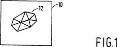
図1は、より高次元の空間における情景の2次元画像10を示す。コンピュータグラフィックス装置において、このような画像10を情景モデルから発生し、この情景モデルは、前記より高次元の空間における表面の数学的表現を与える。前記情景モデルから、どの表面が画像10において可視であるかと、これらが可視である場所とを計算する。ある表面を三角形としてもよく、この表面を、その角点の座標によって数学的に表すことができ、このような三角形表面は、(完全に可視の場合において)画像10における三角形領域として可視である。例として、図1における画像10は、前記情景モデルからの表面を表す多数(例えば、12)の三角形領域によって表されるオブジェクトを含む。
前記画像の現実感を増すために、前記コンピュータグラフィックス装置は、画像10において示される領域においてテクスチャパターンを表示してもよい。これは、テクスチャマッピングによって実現される。
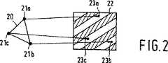
図2は、テクスチャマッピングに含まれるパラメータを示す。図2は、より高次元の空間からの表面の表現の例として三角形20を示す。この図は、テクスチャ座標の関数として斜線縞の強度パターンも示す。この強度パターンは、テクスチャの一例である。さらに、この図は、前記三角形の角21a−cおよびテクスチャ座標点23a−c間の対応を示す。これらの対応は、表面20が指定されたテクスチャ22による強度パターンを伴い、三角形20の角21a−cにおいて、強度値は、前記テクスチャにおける対応する座標点23a−cの強度値であるという、前記情景モデルにおける情報を表す。前記表面における他の点の中間テクスチャ座標点は、角21a−cのテクスチャ座標点23a−cの(2)1次補間に従い、前記テクスチャによってこれらの中間テクスチャ座標点に割り当てられた強度値は、前記表面の強度分布に従う。
前記コンピュータグラフィックス装置は、画像10における画素座標対(x,y)をテクスチャ座標対(u,v)にマッピングする座標マップを計算することによって前記テクスチャマッピング処理を実行する。図2の例に関して、この座標マップは、前記画像上に投影される表面20における中間地点と、角点21a−cおよびテクスチャ座標点23a−c間の対応とに従う。画像10における表面12が可視である領域における各々の画素に関して、前記コンピュータグラフィックス装置は、対応するテクスチャ座標対(u,v)を計算し、このテクスチャ座標対(u,v)に対するテクスチャの値を得る。次にこの値を使用し、前記画素の可視属性を決定する。
テクスチャマッピングは、場所依存色等のような表面の光学属性の表現には良好に働く。テクスチャマッピングは、幾何学的テクスチャの表現にはうまく働かない。
図3は、表面の側面図を示し、幾何学的テクスチャの属性を説明する。この図は、概念上の表面が見られる視点33および視線34を示す。この概念上の表面をギザギザの線31によって示し、この線は、前記概念上の表面の高さ断面が前記表面に沿って非線形的(図においてはそれぞれの部分に関して線型的)に変化することを表す。前記情景モデルにおいて、概念上の表面31を、図3において直線30によって示す平坦表面と、2次元画像10において使用され、前記断面の視覚効果および、吸収または反射における変化のような前記表面の他の属性を説明するテクスチャマッピングとによってモデル化する。
理想的には、テクスチャマッピングは、視点33が変化した場合、前記表面の外観の変化を考慮すべきである。この外観の変化を説明するために、図3は、他の視点35と、この視点からの他の視線36とを示す。表面31の原視点33から不可視である部分が他の視点から可視であり、またはその逆が分かる。これらの部分は、原視点33から可視である部分と異なる光学属性を有するかもしれない。結果として生じる前記表面の外観の変化を視差変化と呼ぶ。さらに、視点33、35から表面31の部分への視線34、36の入射角は、視点33、35が変化する場合、変化する。この結果、視点33、35から見られる前記表面の外観に変化が生じる。この結果として生じる外観の変化を照明変化と呼ぶ。
図4は、表面の他の断面を示し、視点の変化による視差変化を簡単に説明する方法を示す。この方法は、概念的に2つの補助表面を使用し、これらの補助表面の双方は、前記実際の表面と平行に、これらの補助表面間に間隔をとって延在する。前記補助表面の各々に対してテクスチャマップを規定し、例えば、平坦表面30を越える図3の概念的表面31の部分のテクスチャマップを形成することによる一方のテクスチャマップ(概念的表面31が平坦表面30より下にある場合、前記テクスチャを透明にする)と、平坦表面30より下にある概念的表面31の部分の他のテクスチャマップとを規定する。前記補助表面間の間隔を、例えば、各々平坦表面30の上または下にある前記概念的表面の2つの部分の平均高さの差として選択する。前記表面が可視である画像10における領域12におけるテクスチャを説明するために、この領域の各々の画素を、前記補助表面の双方に対して決定する。結果として生じるテクスチャ値を結合し、前記画素の実際の画像寄与を得る。
図4は、2つの視点43、45と、2つの対応する視線44、46とを示す。側面図において、2つの直線40、41は、互いに平行に延在する2つの補助表面を表す。テクスチャ座標対40、41を、各々の補助表面40、41における各々の点に対して規定する。2つの視点43、45からの視線44、46は、第1補助表面40と1個の点47において交差する。これらの視線44、46は、第2補助表面41と2つの異なる点48、49において交差する。一方の視線44上にある第1補助表面40における第1点47と、一方の視点43からの第2補助表面41における第2点48とは、他方の視点45からの第2補助表面41における第3点49と共に、一方の視線上にある。したがって、前記第1補助表面上の第1点のテクスチャ座標対(u,v)にマッピングされる画素座標対(x,y)を、視点43、45に応じて、第2補助表面41上の点の第2または第3テクスチャ座標対にマッピングする。個々のテクスチャが、2つの補助表面40、41と、例えば、第1テクスチャの透明度状態に応じて第1テクスチャまたは第2テクスチャを使用する、画素マップが結合され前記画像を説明する前記テクスチャ値とに関係する場合、この結果、前記視点に応じて前記画像の外観において変化が生じる。この外観の変化は、視差変化をシミュレートする。2つ以上のテクスチャを使用し、より複雑な視差変化をシミュレートしてもよく、この場合において、各々のテクスチャを、例えば、補助表面のスタックにおける異なった補助表面に関係させる。次に、特定の補助表面の上にある補助表面に関係するすべてのテクスチャが「透明」状態をある画素にマッピングする場合、この特定の補助表面に関係するテクスチャ値をこの画素に使用する。
前記画像の実際の計算に関して、前記補助表面を構成する必要はなく、前記マップ間の差を、前記視点から前記表面上のマッピングされた場所への視線の入射ベクトルから決定することができる。このベクトルを、視線44および前記表面に対する法線間の角度(と、前記表面上の視線44の標準投影の、前記表面上のテクスチャ座標系のuv座標軸に対する方向)とによって規定する(表面上の点の標準投影は、前記点を法線と平行にシフトすることによって得られる表面点である)。前記テクスチャマップ間のオフセットは、好適には、tg()と、前記補助表面間の変移とに比例する大きさと、前記標準投影の方向(に依存する前記テクスチャ座標軸に対する方向)とを有する。
他の依存性も使用できる。例えば、前記視点および表面間の媒質の屈折率「nb」と異なる屈折率「na」を有する、ガラスのような、前記補助表面間の屈折性層をシミュレートできる。この場合において、前記座標マップ間の差は、スネル(Snellius)の法則に従う(sin(/sqrt((na/nb)2−sin2())に比例するオフセット)。依存性は、前記表面における場所における依存性も含み、例えば、「でこぼこ」補助表面を、各々のテクスチャ座標に対して規定されるオフセットに対する比例係数でモデル化してもよい。
多くの場合において、特に、前記表面がマッピングする領域が小さい場合、前記2つの補助表面に関する座標マップ間の差を、画素独立シフトによって近似することができ、これを前記表面における視点からの視線の入射ベクトルから、前記表面全体に対して1回計算することができる。
3次元モデル空間の代わりに、より高次元のモデル空間を使用してもよく、例えば、起伏するガラスを表す表面において、表面の視差効果が時間の関数として変化する時間依存3次元空間を使用してもよい。この場合において、前記座標マップ間のオフセットを、前記視点の時間座標の関数として調節してもよい。
図5は、本発明を実行する概念化したコンピュータグラフィックス装置である。この装置は、可視度計算ユニット51に結合され、情景モデルを格納するメモリ52を含む。画素選択器50も可視度計算ユニット51に結合する。可視度計算ユニット51の出力部を、第1テクスチャメモリ54に結合すると共に、座標シフトユニット56を経て第2テクスチャメモリ55に結合する。第1および第2テクスチャメモリ54、55の出力部を結合ユニット57に結合し、この結合ユニット57は、表示ユニット58に結合された出力部を有する。
動作において、可視度計算ユニット51は、視点VPの仕様を受け、メモリ52に格納された情景モデルにおいて規定された表面のうちどれが、発生すべき画像における視点から可視であるかを計算する。可視度計算ユニット51は、前記画像において各々の表面が可視である場所も決定する。画素選択器50は、連続する画素を選択し、これらの画素座標対(x,y)を可視度計算ユニット51に送信する。それに応じて、可視度計算ユニット51は、どの表面が前記画素において可視であるかを決定し、可視度計算ユニット51は、使用すべきテクスチャと、前記画素座標対をマッピングするテクスチャ座標対(u,v)とを合図する。このテクスチャ座標対(u,v)を、第1テクスチャメモリ54に対するアドレスとして使用する。座標シフトユニット56において、前記表面に対して前記可視度計算ユニットによって合図される座標シフトを、テクスチャ座標(u,v)に加える。結果として生じるシフトされたテクスチャ座標(u’,v’)を使用し、第2テクスチャメモリ55をアドレスする。このようにテクスチャメモリ54、55においてアドレスされたテクスチャ値を、結合ユニット57において結合し、表示ユニット58によって画素座標(x,y)において視覚的に表示する。
可視度計算ユニット51は、前記座標シフトを所定の視点に対して、または、前記表面における場所の関数として、表面ごとに1回計算する。結合ユニット57は、前記テクスチャ値を種々の方法において結合することができる。好適な方法において、テクスチャメモリ54、55のうち一方は、「透明度状態」の前記テクスチャ値を示す。好適には、前記透明度を示すのに使用されるテクスチャを、「視差的に最高に」現れるテクスチャ、すなわち、このテクスチャに対して他のテクスチャのオフセットが、前記視点が変化した場合、前記視点の動きの方向と逆方向においてシフトするテクスチャとする。透明度が示される場合、他方のテクスチャメモリ54、55からのテクスチャ値を使用する。他の場合、一方のテクスチャメモリ54、55は、それ自体のテクスチャ値を発し、この値のみを使用する。もちろん、前記結合ユニットにおいてテクスチャ値を加えるか、アルファチャネルを使用し、一方のテクスチャの部分的な透明度等をシミュレートしてもよい。
より複雑な視差効果に関して、どのような数の追加のテクスチャメモリを使用してもよく、各々のテクスチャメモリは、そのアドレスを前記可視度計算ユニットから、テクスチャ座標(u,v)に、可視度計算ユニット51によってそのテクスチャメモリに合図される座標シフトを加えるそれ自体の座標シフトユニットを経て受ける。この場合において、結合ユニット57は、これらのテクスチャメモリの各々からのテクスチャを結合する。
実際には、前記テクスチャ値を、同じテクスチャメモリから異なるテクスチャを使用して、並列の代わりに逐次的に計算してもよい。画素選択器50と、可視度計算ユニット51と、結合ユニット57と、座標シフトユニット56とを、適切にプログラムされたコンピュータにおいて結合してもよく、1個以上のテクスチャメモリ54、55と、メモリ52とを結合してもよい。前記1個以上のテクスチャメモリを、通常、異なった解像度におけるテクスチャを格納する「ミップマップ」メモリとし、前記コンピュータグラフィックス装置が適切な解像度を選択する。実際には、前記コンピュータグラフィックス装置は、前記得られたテクスチャ値またはこれらの組み合わせを、ある後処理に使用し、例えば、前記テクスチャが前記表面の吸収または反射パラメータを与える場合、照明状態を考慮してもよい。
【図面の簡単な説明】
図1は、より高次元の情景の2次元画像を示す。
図2は、テクスチャマッピングに含まれるパラメータを説明する。
図3は、表面の側面図を示す。
図4は、他の側面図を示す。
図5は、2次元画像を発生する装置を示す。DETAILED DESCRIPTION OF THE INVENTION The present invention relates to a method for generating a two-dimensional image of a surface in a higher dimensional model space, the method comprising:
-Selecting a viewpoint for the surface;
-Determining a region in the image where the surface is visible from the viewpoint;
Texture mapping a texture on the region according to a coordinate map.
The present invention relates to a mapping unit for mapping a surface modeled from a three-dimensional or higher-dimensional space onto a region of pixels in a two-dimensional image, and a texture mapping unit for mapping a texture onto pixels of the region according to a coordinate map It also relates to computer graphics devices that have
Such a device is known, for example, from GB-A-2288304.
In computer graphics, a two-dimensional visual image is generated as if a mathematically modeled surface in a higher dimensional space is viewed from a selectable viewpoint in this higher dimensional space. Texture mapping is used on the surface to increase the realism of the image. The surface model specifies the texture and the correspondence between the surface position and the texture coordinates (u, v). This correspondence follows a coordinate map that maps pixels (x, y) in the region in the image where the surface is visible to texture coordinates (u, v). A pixel in such a region having a pixel coordinate pair (x, y) is assigned to the texture coordinate pair (u, v) mapped by the pixel coordinate pair (x, y) by the texture in the image. Described according to attributes.
Texture mapping gives good results in the expression of optical textures such as coloring. Texture mapping is a representation of a geometric texture, such as a texture related to bumps (bumps) on the surface, where the appearance of such a texture depends on the direction in which it is viewed and the pixels on the surface It does not work well because it simply does not depend on the position of This is different because texture mapping simulates images from different viewpoints of the same surface, eg, moving through the higher dimensional space or simulating stereoscopic image pairs. If you have to calculate for a surface that looks different from an angle, this means you lack realism.
In order to increase the realism of the image in such situations, a texture mapping method must be provided that can change the appearance of the mapped texture as a function of the direction in which the surface is viewed.
It is known to achieve this by supplementing the texture with a surface normal perturbation function as a function of the texture coordinates. In calculating the image contribution of a pixel having a certain pixel coordinate pair (x, y) in a region where the surface is visible, the texture coordinate pair to which the pixel coordinate pair (x, y) maps a perturbed normal. Calculate by perturbing the surface normal according to the perturbation function values for (u, v). Thereafter, the parameter of the light reaching the viewpoint through the surface is calculated according to the perturbed surface normal. This makes it possible to represent light and dark changes due to bumps on the surface, but not parallax changes. Furthermore, the calculation of the perturbed surface normal is a resource intensive operation.
In particular, an object of the present invention is to provide a computer graphics method and apparatus capable of generating a parallax effect in texture with a small overhead. The method according to the invention comprises: at least one other texture is texture-mapped in the region according to another coordinate map and the relative offset between the coordinate map and the other coordinate map is adjusted according to the viewpoint; Rendering in the region a combination of the mapped texture and other mapped textures. Thus, at least two texture maps are used for the same surface, each of which includes its own texture that assigns visual attributes as a function of the texture coordinate pair (u, v). Each texture map also defines its own coordinate map, which maps a pixel coordinate pair (x, y) in the region where the surface is visible to a texture coordinate pair (u, v). The coordinate map defined by the different texture maps is different in the direction in which the surface is viewed to simulate the effect of different spacings between the surface and the conceptual surface with the corresponding texture. Dependent. For pixels where the surface belongs to the visible region, individual visual attributes are determined by mapping each texture map that uses a conventional texture to the surface. The pixels are depicted in the image according to a combination of these visual attributes. These necessary calculations are as many as those required for conventional texture mapping. Thus, the parallax change of the texture can be depicted better and more complex calculation than conventional texture mapping.
In an embodiment of the method according to the present invention, the relative offsethavinga direction ofnormal projection of the line of sight to the surface from the viewpoint in said surface, as a function of the angle between the normal line the relative offset for the line of sight and the surface It has a certain size. The magnitude is proportional to, for example, the angle between the normal and line of sight (tangent function tg ()) to model the spacing between two conceptual deformations of the surface with the individual texture . Instead, the dependence of the size on (can simulate the effect of a layer having a different refractive index than the surroundings between the two conceptual deformations of the surface.
In another embodiment, if the value of the first texture indicates an opaque state at a pixel in the image, only this texture is depicted in the pixel, and if the value of the texture indicates a transparent state, the other texture Are used to determine the pixel. Thus, the first of the textures assigns the transparency state as a function of texture coordinates (u, v). If a pixel having pixel coordinates (x, y) is assigned to an individual texture coordinate pair (u, v) to which the transparency state “opaque” is mapped by these pixel coordinates (x, y), the second of the texture Rendering according to one and assigning the pixel to the individual texture coordinate pair (u, v) to which the pixel coordinates (x, y) map the transparency state “transparent”. Describe according to things.
Preferably, the texture that determines the transparency is a texture that seems to have the highest parallax effect. This appearance depends on the adjustment of the offset, i.e., in response to changes in the viewpoint, one coordinate map is relatively more in the opposite direction than the change in the viewpoint than the other coordinate map (i.e. in the viewpoint). When shifting (less in the direction of the change), the parallax effect causes the texture associated with the one coordinate map to appear to be below the texture associated with the other coordinate map.
These and other advantageous aspects of the invention are described in more detail using the following figures.
FIG. 1 shows a two-
In order to increase the realism of the image, the computer graphics device may display a texture pattern in the area shown in the
FIG. 2 shows parameters included in the texture mapping. FIG. 2 shows a
The computer graphics device performs the texture mapping process by calculating a coordinate map that maps a pixel coordinate pair (x, y) in the
Texture mapping works well for representing surface optical attributes such as location-dependent colors. Texture mapping does not work well for representing geometric textures.
FIG. 3 shows a side view of the surface and describes the attributes of the geometric texture. This figure shows a
Ideally, texture mapping should take into account changes in the appearance of the surface when the
FIG. 4 shows another cross section of the surface and shows a method for briefly explaining the parallax change due to the change of the viewpoint. This method conceptually uses two auxiliary surfaces, both of which extend parallel to the actual surface and with a spacing between them. The defining a texture map for each of the auxiliary surface, for example, one of the texture map by forming a texture map of a portion of the
FIG. 4 shows two
For the actual calculation of the image, it is not necessary to construct the auxiliary surface, and the difference between the maps can be determined from the line of sight incidence vector from the viewpoint to the mapped location on the surface. This vector is defined by the angle between the line of sight 44 and the normal to the surface (and the direction of thestandard projection of the line of sight 44 on the surface relative to the uv coordinate axis of the texture coordinate system on the surface) (on the surface). Astandard projection of a point is a surface point obtained by shifting the point parallel to the normal). The offset between the texture maps preferably has a magnitude proportional to tg () and the transition between the auxiliary surfaces and the direction of thestandard projection (depending on the direction relative to the texture coordinate axis).
Other dependencies can also be used. For example, a refractive layer between the auxiliary surfaces can be simulated, such as glass, having a refractive index “na” that is different from the refractive index “nb” of the medium between the viewpoint and the surface. In this case, the difference between the coordinate map, according to the law of shinLe (Snellius) (sin (/ sqrt ((na / nb) offset proportional to 2-sin2 ())). Dependence on said surface For example, a “bumpy” auxiliary surface may be modeled with a proportionality factor for the offset defined for each texture coordinate.
In many cases, especially when the area to which the surface maps is small, the difference between the coordinate maps for the two auxiliary surfaces can be approximated by a pixel independent shift, which is the line of sight from the viewpoint on the surface. From the incident vector, it can be calculated once for the entire surface.
Instead of a 3D model space, a higher dimensional model space may be used, for example, using a time-dependent 3D space where the parallax effect of the surface changes as a function of time on the surface representing the undulating glass. May be. In this case, the offset between the coordinate maps may be adjusted as a function of the time coordinate of the viewpoint.
FIG. 5 is a conceptualized computer graphics device that implements the present invention. The device includes a
In operation, the
The
For more complex parallax effects, any number of additional texture memories may be used, each texture memory having its address from the visibility calculation unit to the texture coordinates (u, v), visibility The
In practice, the texture values may be calculated sequentially instead of in parallel using different textures from the same texture memory. The
[Brief description of the drawings]
FIG. 1 shows a two-dimensional image of a higher dimensional scene.
FIG. 2 illustrates parameters included in the texture mapping.
FIG. 3 shows a side view of the surface.
FIG. 4 shows another side view.
FIG. 5 shows an apparatus for generating a two-dimensional image.
Claims (6)
Translated fromJapanese前記表面に対する視点を選択するステップと、
前記表面が前記視点から見て可視である前記画像内の領域を決定するステップと、
第1座標マップに従って、前記領域上に第1テクスチャをテクスチャマッピングするステップと
を具える方法において、
少なくとも第2テクスチャを、第2座標マップに従って前記領域内にテクスチャマッピングし、前記第1座標マップと前記第2座標マップとの間の相対オフセットを、前記視点に応じて調節するステップと、
テクスチャマッピングした前記第1テクスチャと、テクスチャマッピングした前記第2テクスチャとの組み合わせを、前記領域内に描写するステップと
を具えていることを特徴とする方法。A method for generating a two-dimensional image of a surface in a higher dimensional model space, comprising:
Selecting a viewpoint for the surface;
Determining a regionin the image where the surface is visible from the viewpoint;
Texture mapping afirst texture on the region according to afirst coordinate map,
The method comprising at least asecond texture, and texture mappingin the region in accordance witha second coordinate map, a relative offsetbetween thefirst coordinate mapand the second coordinate map, adjusted according to the viewpoint,
How tothefirst texturetexturemapping, the combination ofthe second texturetexture mapping, characterized in that it comprises a step of representationin theregion.
第1座標マップに従って第1テクスチャを前記領域の画素にテクスチャマッピングするテクスチャマッピングユニットとを具えるコンピュータグラフィックス装置において、
前記テクスチャマッピングユニットが、少なくとも第2テクスチャを第2座標マップに従って前記領域の画素にテクスチャマッピングするように構成され、前記テクスチャマッピングユニットが、前記第1座標マップと前記第2座標マップとの間の相対オフセットを、前記表面上の視点に応じて調節し、前記コンピュータグラフィックス装置が、前記領域内の前記画素にテクスチャマッピングされるテクスチャ値の結合を、前記第1テクスチャおよび前記第2テクスチャから形成する結合ユニットを具えることを特徴とするコンピュータグラフィックス装置。A mapping unit that maps a modeled surface from a 3D or higher dimensional space to a regionof pixels in a 2D image;
A computer graphics device comprising: a texture mapping unit thattexture maps afirst texture to pixels of the region according to afirst coordinate map;
The texture mapping unitis configured totexture mapping at least asecond texture to the pixel of the regionaccording to a second coordinate map, the texture mapping unit,between thefirst coordinate mapand the second coordinate map forming a relative offset, adjustedin accordance with the view pointon said surface,said computer graphics system, the binding ofthe texture valuethat will betexture mapped tothe pixelsof thearea, from the first texture andthe second texture A computer graphics device comprising a coupling unit.
Applications Claiming Priority (3)
| Application Number | Priority Date | Filing Date | Title |
|---|---|---|---|
| EP96203265 | 1996-11-21 | ||
| EP96203265.2 | 1996-11-21 | ||
| PCT/IB1997/001307WO1998022911A1 (en) | 1996-11-21 | 1997-10-20 | Method and apparatus for generating a computer graphics image |
Publications (2)
| Publication Number | Publication Date |
|---|---|
| JP2000504453A JP2000504453A (en) | 2000-04-11 |
| JP4071290B2true JP4071290B2 (en) | 2008-04-02 |
Family
ID=8224606
Family Applications (1)
| Application Number | Title | Priority Date | Filing Date |
|---|---|---|---|
| JP52338498AExpired - Fee RelatedJP4071290B2 (en) | 1996-11-21 | 1997-10-20 | Method and apparatus for generating computer graphics images |
Country Status (5)
| Country | Link |
|---|---|
| US (1) | US6049337A (en) |
| EP (1) | EP0877991B1 (en) |
| JP (1) | JP4071290B2 (en) |
| DE (1) | DE69718291T2 (en) |
| WO (1) | WO1998022911A1 (en) |
Families Citing this family (29)
| Publication number | Priority date | Publication date | Assignee | Title |
|---|---|---|---|---|
| US6317525B1 (en)* | 1998-02-20 | 2001-11-13 | Ati Technologies, Inc. | Method and apparatus for full scene anti-aliasing |
| US7071949B1 (en)* | 1998-11-18 | 2006-07-04 | Microsoft Corporation | View dependent tiled textures |
| AU2459700A (en)* | 1999-02-19 | 2000-09-04 | Sony Computer Entertainment Inc. | System for and method of implementing refraction mapping |
| US6297834B1 (en)* | 1999-06-10 | 2001-10-02 | Hewlett-Packard Company | Direction-dependent texture maps in a graphics system |
| WO2001006462A1 (en)* | 1999-07-20 | 2001-01-25 | Koninklijke Philips Electronics N.V. | Method and apparatus for computing a computer graphics image of a textured surface |
| US6784882B1 (en)* | 1999-09-10 | 2004-08-31 | Sony Computer Entertainment Inc. | Methods and apparatus for rendering an image including portions seen through one or more objects of the image |
| US6618048B1 (en) | 1999-10-28 | 2003-09-09 | Nintendo Co., Ltd. | 3D graphics rendering system for performing Z value clamping in near-Z range to maximize scene resolution of visually important Z components |
| US6717577B1 (en) | 1999-10-28 | 2004-04-06 | Nintendo Co., Ltd. | Vertex cache for 3D computer graphics |
| JP3367934B2 (en)* | 2000-03-24 | 2003-01-20 | 株式会社コナミコンピュータエンタテインメントジャパン | Game system, image drawing method in game system, and computer-readable recording medium storing game program |
| US7119813B1 (en) | 2000-06-02 | 2006-10-10 | Nintendo Co., Ltd. | Variable bit field encoding |
| US6636214B1 (en) | 2000-08-23 | 2003-10-21 | Nintendo Co., Ltd. | Method and apparatus for dynamically reconfiguring the order of hidden surface processing based on rendering mode |
| US6980218B1 (en) | 2000-08-23 | 2005-12-27 | Nintendo Co., Ltd. | Method and apparatus for efficient generation of texture coordinate displacements for implementing emboss-style bump mapping in a graphics rendering system |
| US6700586B1 (en) | 2000-08-23 | 2004-03-02 | Nintendo Co., Ltd. | Low cost graphics with stitching processing hardware support for skeletal animation |
| US7538772B1 (en) | 2000-08-23 | 2009-05-26 | Nintendo Co., Ltd. | Graphics processing system with enhanced memory controller |
| US7061502B1 (en) | 2000-08-23 | 2006-06-13 | Nintendo Co., Ltd. | Method and apparatus for providing logical combination of N alpha operations within a graphics system |
| US6825851B1 (en) | 2000-08-23 | 2004-11-30 | Nintendo Co., Ltd. | Method and apparatus for environment-mapped bump-mapping in a graphics system |
| US6937245B1 (en) | 2000-08-23 | 2005-08-30 | Nintendo Co., Ltd. | Graphics system with embedded frame buffer having reconfigurable pixel formats |
| US7002591B1 (en) | 2000-08-23 | 2006-02-21 | Nintendo Co., Ltd. | Method and apparatus for interleaved processing of direct and indirect texture coordinates in a graphics system |
| US7196710B1 (en) | 2000-08-23 | 2007-03-27 | Nintendo Co., Ltd. | Method and apparatus for buffering graphics data in a graphics system |
| US7576748B2 (en) | 2000-11-28 | 2009-08-18 | Nintendo Co. Ltd. | Graphics system with embedded frame butter having reconfigurable pixel formats |
| US6707458B1 (en) | 2000-08-23 | 2004-03-16 | Nintendo Co., Ltd. | Method and apparatus for texture tiling in a graphics system |
| US6867781B1 (en) | 2000-08-23 | 2005-03-15 | Nintendo Co., Ltd. | Graphics pipeline token synchronization |
| US7034828B1 (en) | 2000-08-23 | 2006-04-25 | Nintendo Co., Ltd. | Recirculating shade tree blender for a graphics system |
| US7184059B1 (en) | 2000-08-23 | 2007-02-27 | Nintendo Co., Ltd. | Graphics system with copy out conversions between embedded frame buffer and main memory |
| US6811489B1 (en) | 2000-08-23 | 2004-11-02 | Nintendo Co., Ltd. | Controller interface for a graphics system |
| JP4714919B2 (en)* | 2000-09-13 | 2011-07-06 | 株式会社東京大学Tlo | Rendering device, recording medium, and program |
| JP4079358B2 (en)* | 2002-12-06 | 2008-04-23 | 株式会社コナミデジタルエンタテインメント | GAME DEVICE, GAME CONTROL METHOD, AND PROGRAM |
| JP2006252423A (en)* | 2005-03-14 | 2006-09-21 | Namco Bandai Games Inc | Program, information storage medium, and image generation system |
| CN113259642B (en)* | 2021-05-12 | 2023-05-30 | 华强方特(深圳)科技有限公司 | Film visual angle adjusting method and system |
Family Cites Families (6)
| Publication number | Priority date | Publication date | Assignee | Title |
|---|---|---|---|---|
| WO1993023835A1 (en)* | 1992-05-08 | 1993-11-25 | Apple Computer, Inc. | Textured sphere and spherical environment map rendering using texture map double indirection |
| JPH07325934A (en)* | 1992-07-10 | 1995-12-12 | Walt Disney Co:The | Method and equipment for provision of graphics enhanced to virtual world |
| US5680531A (en)* | 1993-07-02 | 1997-10-21 | Apple Computer, Inc. | Animation system which employs scattered data interpolation and discontinuities for limiting interpolation ranges |
| CA2144914A1 (en)* | 1994-04-01 | 1995-10-02 | Raymond L. Fitzgerald | Computer graphics texture paging system with fragmentary mip map selection |
| EP0707288B1 (en)* | 1994-10-14 | 2003-08-27 | Canon Kabushiki Kaisha | Image processing method and apparatus |
| US5760783A (en)* | 1995-11-06 | 1998-06-02 | Silicon Graphics, Inc. | Method and system for providing texture using a selected portion of a texture map |
- 1997
- 1997-10-20JPJP52338498Apatent/JP4071290B2/ennot_activeExpired - Fee Related
- 1997-10-20DEDE69718291Tpatent/DE69718291T2/ennot_activeExpired - Lifetime
- 1997-10-20WOPCT/IB1997/001307patent/WO1998022911A1/enactiveIP Right Grant
- 1997-10-20EPEP97943112Apatent/EP0877991B1/ennot_activeExpired - Lifetime
- 1997-11-19USUS08/972,977patent/US6049337A/ennot_activeExpired - Lifetime
Also Published As
| Publication number | Publication date |
|---|---|
| EP0877991B1 (en) | 2003-01-08 |
| JP2000504453A (en) | 2000-04-11 |
| EP0877991A1 (en) | 1998-11-18 |
| WO1998022911A1 (en) | 1998-05-28 |
| US6049337A (en) | 2000-04-11 |
| DE69718291T2 (en) | 2003-11-13 |
| DE69718291D1 (en) | 2003-02-13 |
Similar Documents
| Publication | Publication Date | Title |
|---|---|---|
| JP4071290B2 (en) | Method and apparatus for generating computer graphics images | |
| Darsa et al. | Navigating static environments using image-space simplification and morphing | |
| US7068274B2 (en) | System and method for animating real objects with projected images | |
| US7652675B2 (en) | Dynamically adjusted brush for direct paint systems on parameterized multi-dimensional surfaces | |
| US6888544B2 (en) | Apparatus for and method of rendering 3D objects with parametric texture maps | |
| US7019748B2 (en) | Simulating motion of static objects in scenes | |
| US6078333A (en) | Images and apparatus for carrying out the method | |
| CN100492412C (en) | Voxel Data Generation Method in Volumetric 3D Display | |
| JPH11514118A (en) | 3D image generation | |
| JPH0757117A (en) | Method and computer controlled display system for generating an index to a texture map | |
| Yang et al. | Nonlinear perspective projections and magic lenses: 3D view deformation | |
| CN101226644B (en) | Method for tracing shade and shadow of space two-dimension image | |
| US7071937B1 (en) | Dirt map method and apparatus for graphic display system | |
| EP0856815B1 (en) | Method and system for determining and/or using illumination maps in rendering images | |
| US20060114262A1 (en) | Texture mapping apparatus, method and program | |
| EP1112553B1 (en) | Method and apparatus for computing a computer graphics image of a textured surface | |
| KR100559127B1 (en) | Image processing device | |
| KR950025512A (en) | Hardware-based graphical workstation solution for refraction | |
| Haines et al. | Real-time shadows | |
| CN116342784B (en) | Real-time rendering method for large scene water interaction | |
| JP4736239B2 (en) | Pattern image creating method and apparatus | |
| JP3867071B2 (en) | Image processing apparatus and image processing method | |
| CA2282240C (en) | System and computer-implemented method for modeling the three-dimensional shape of an object by shading of a two-dimensional image of the object | |
| JP4668447B2 (en) | Pattern image creating method and apparatus | |
| Yuan | X. Yuan |
Legal Events
| Date | Code | Title | Description |
|---|---|---|---|
| A621 | Written request for application examination | Free format text:JAPANESE INTERMEDIATE CODE: A621 Effective date:20041019 | |
| A131 | Notification of reasons for refusal | Free format text:JAPANESE INTERMEDIATE CODE: A131 Effective date:20070821 | |
| A521 | Request for written amendment filed | Free format text:JAPANESE INTERMEDIATE CODE: A523 Effective date:20071120 | |
| RD02 | Notification of acceptance of power of attorney | Free format text:JAPANESE INTERMEDIATE CODE: A7422 Effective date:20071120 | |
| TRDD | Decision of grant or rejection written | ||
| A01 | Written decision to grant a patent or to grant a registration (utility model) | Free format text:JAPANESE INTERMEDIATE CODE: A01 Effective date:20080115 | |
| A61 | First payment of annual fees (during grant procedure) | Free format text:JAPANESE INTERMEDIATE CODE: A61 Effective date:20080117 | |
| R150 | Certificate of patent or registration of utility model | Free format text:JAPANESE INTERMEDIATE CODE: R150 | |
| FPAY | Renewal fee payment (event date is renewal date of database) | Free format text:PAYMENT UNTIL: 20110125 Year of fee payment:3 | |
| FPAY | Renewal fee payment (event date is renewal date of database) | Free format text:PAYMENT UNTIL: 20110125 Year of fee payment:3 | |
| FPAY | Renewal fee payment (event date is renewal date of database) | Free format text:PAYMENT UNTIL: 20120125 Year of fee payment:4 | |
| FPAY | Renewal fee payment (event date is renewal date of database) | Free format text:PAYMENT UNTIL: 20120125 Year of fee payment:4 | |
| FPAY | Renewal fee payment (event date is renewal date of database) | Free format text:PAYMENT UNTIL: 20130125 Year of fee payment:5 | |
| FPAY | Renewal fee payment (event date is renewal date of database) | Free format text:PAYMENT UNTIL: 20140125 Year of fee payment:6 | |
| LAPS | Cancellation because of no payment of annual fees |