JP4070868B2 - Endoscope insertion part - Google Patents
Endoscope insertion partDownload PDFInfo
- Publication number
- JP4070868B2 JP4070868B2JP07296798AJP7296798AJP4070868B2JP 4070868 B2JP4070868 B2JP 4070868B2JP 07296798 AJP07296798 AJP 07296798AJP 7296798 AJP7296798 AJP 7296798AJP 4070868 B2JP4070868 B2JP 4070868B2
- Authority
- JP
- Japan
- Prior art keywords
- flexible tube
- insertion portion
- endoscope
- pipe
- flexibility
- Prior art date
- Legal status (The legal status is an assumption and is not a legal conclusion. Google has not performed a legal analysis and makes no representation as to the accuracy of the status listed.)
- Expired - Fee Related
Links
- 238000003780insertionMethods0.000titleclaimsdescription19
- 230000037431insertionEffects0.000titleclaimsdescription19
- 230000002093peripheral effectEffects0.000claimsdescription5
- 230000000452restraining effectEffects0.000claimsdescription5
- 229910045601alloyInorganic materials0.000claimsdescription2
- 239000000956alloySubstances0.000claimsdescription2
- 238000005452bendingMethods0.000description10
- 239000002184metalSubstances0.000description6
- 229910052751metalInorganic materials0.000description6
- XLYOFNOQVPJJNP-UHFFFAOYSA-NwaterSubstancesOXLYOFNOQVPJJNP-UHFFFAOYSA-N0.000description4
- 230000001629suppressionEffects0.000description3
- BQCADISMDOOEFD-UHFFFAOYSA-NSilverChemical compound[Ag]BQCADISMDOOEFD-UHFFFAOYSA-N0.000description2
- 239000000835fiberSubstances0.000description2
- 238000005286illuminationMethods0.000description2
- 238000004519manufacturing processMethods0.000description2
- 239000000463materialSubstances0.000description2
- 238000000465mouldingMethods0.000description2
- 230000003287optical effectEffects0.000description2
- 239000013307optical fiberSubstances0.000description2
- 210000000056organAnatomy0.000description2
- 229910052709silverInorganic materials0.000description2
- 239000004332silverSubstances0.000description2
- 229910001220stainless steelInorganic materials0.000description2
- 229920003002synthetic resinPolymers0.000description2
- 239000000057synthetic resinSubstances0.000description2
- 229910004337Ti-NiInorganic materials0.000description1
- 229910011209Ti—NiInorganic materials0.000description1
- HZEWFHLRYVTOIW-UHFFFAOYSA-N[Ti].[Ni]Chemical compound[Ti].[Ni]HZEWFHLRYVTOIW-UHFFFAOYSA-N0.000description1
- 238000005219brazingMethods0.000description1
- 230000000694effectsEffects0.000description1
- 238000001125extrusionMethods0.000description1
- KHYBPSFKEHXSLX-UHFFFAOYSA-NiminotitaniumChemical compound[Ti]=NKHYBPSFKEHXSLX-UHFFFAOYSA-N0.000description1
- 230000002401inhibitory effectEffects0.000description1
- 229920005749polyurethane resinPolymers0.000description1
- 239000010935stainless steelSubstances0.000description1
- 238000003466weldingMethods0.000description1
Images


Landscapes
- Instruments For Viewing The Inside Of Hollow Bodies (AREA)
- Endoscopes (AREA)
Description
Translated fromJapanese【0001】
【発明の属する技術分野】
この発明は、体腔内等に挿入される内視鏡の挿入部に関する。
【0002】
【従来の技術】
いわゆる軟性内視鏡の挿入部は、光学繊維束等の内蔵物を外装可撓管内に挿通配置して構成されているが、その先端寄りの部分は体腔内臓器の形状に沿って比較的自由に曲がるように柔軟に形成し、手元側の部分は操作者が行う微妙な押し引き動作等が先端側に伝達されるように硬めに形成する必要がある。
【0003】
そこで従来は、外装可撓管の最外層の合成樹脂外皮の厚さや硬度等を位置によって変化させることにより、外装可撓管自体の可撓性を途中で変化させていた。
【0004】
【発明が解決しようとする課題】
外装可撓管の最外層の合成樹脂外皮は、一般に押し出し成形によって形成されるが、その厚さや硬度をいちいち途中で変化させる製法では、外装可撓管の製造に著しい時間とコストがかかってしまう。また、そのように途中で成形条件を変化させると、成形条件の変動に起因する製品毎の可撓性のバラツキが発生する場合が少なくない。
【0005】
そこで本発明は、可撓管の外皮の厚さや硬度を変化させることなく、途中で可撓性を容易かつ滑らかに変化させた内視鏡の挿入部を提供することを目的とする。
【0006】
【課題を解決するための手段】
上記の目的を達成するため、本発明の内視鏡の挿入部は、挿入部を外装する可撓管内に、操作ワイヤを挿通して案内するための密着巻きコイルパイプからなる複数のワイヤガイドが挿通配置された内視鏡の挿入部において、上記複数のワイヤガイドの中の少なくとも一つのワイヤガイドの上記可撓管内に位置する部分のうち、上記可撓管の基端位置から中間位置までの範囲に、そのワイヤガイドの周囲の空間形状に対応した断面形状の超弾性合金製の可撓性抑制用パイプを被嵌したことを特徴とする。
【0007】
なお、上記複数のワイヤガイドのうち少なくとも二つのワイヤガイドに、上記可撓性抑制用パイプが互いの先端位置をずらして被嵌されていてもよく、上記可撓性抑制用パイプが、上記ワイヤガイドに固着された一対のストッパ部材の間に挟み込まれて固定されていてもよい。
【0008】
また、上記可撓性抑制用パイプの断面形状が楕円形であってもよく、上記可撓管の内周面に沿う面を有していてもよい。
【0009】
【発明の実施の形態】
図面を参照して本発明の実施の形態を説明する。
図2は内視鏡を示しており、体腔内等に挿入される挿入部は、可撓管2によって外装された軟性部分の先端に、操作部1からの遠隔操作によって屈曲する湾曲部3が連結され、その湾曲部3の先端に、対物光学系等を内蔵した先端部本体4が連結されて構成されている。
【0010】
先端部本体4の表面には、対物光学系に観察像を導入する観察窓5、観察視野に向けて照明光を射出する照明窓6、処置具挿通チャンネル出口7a、及び図示が省略されている送気送水ノズル等が配置されている。
【0011】
可撓管2の基端に連結された操作部1には、湾曲部3を屈曲操作するための湾曲操作ノブ8a,8bが配置されており、上下方向用湾曲操作ノブ8aで上下方向のいずれかの操作ワイヤを牽引操作し、左右方向用湾曲操作ノブ8bで左右方向のいずれかの操作ワイヤを牽引操作することにより、湾曲部3を任意の方向に屈曲させることができる。
【0012】
操作部1には、その他にも、送気送水操作ボタン11、吸引操作ボタン12及び処置具挿入口7b等が配置されている。14は、図示されていない光源装置に接続されるライトガイドケーブルである。
【0013】
図1は、挿入部の可撓管2部分を示している。可撓管2は外径が5〜15mm程度、長さが50〜150cm程度であるが、判り易くするために、実際より太く短く図示されている。
【0014】
可撓管2は、例えば金属帯材製の螺旋管に網状管を被覆し、その外面にポリウレタン樹脂等の外皮を被覆して構成されているが、その各々の図示は省略されている。また、内部に挿通配置されている光学繊維束やチューブ類等の図示も省略されている。
【0015】
なお、可撓管2を被覆する外皮部分はどのような構造であっても差し支えないが、途中で外皮の厚さや硬度を異ならせて可撓管2自体の可撓性を変化させる必要はない。
【0016】
可撓管2の基端部分には、操作部1に連結するための基端連結口金21が取り付けられ、可撓管2の先端部分には、湾曲部3を連結するための先端連結筒22が取り付けられている。
【0017】
先端連結筒22は、例えばステンレス鋼管材によって形成されており、III−III断面が図3に示されるように、四本の操作ワイヤ23を緩く挿通して案内するワイヤガイド24の先端部分が、90°間隔にスポット溶接又は銀ロー付け等によって内周面に固着されている。
【0018】
図1には、4組ある操作ワイヤ23とワイヤガイド24のうちの2組が示されている。ワイヤガイド24は、ステンレス鋼線を一定の径で密着巻きしたコイルパイプによって形成されており、各操作ワイヤ23の先端は、湾曲部3の先端部分に連結されている。
【0019】
ワイヤガイド24の基端部分は、操作部1内の図示されていない湾曲操作機構フレームに固定されており、両端部以外の部分は自由な状態で可撓管2内に挿通配置されている。
【0020】
このように配置されたワイヤガイド24に対して、可撓管2の基端位置から中間位置までの範囲に、超弾性金属製のパイプ材からなる可撓性抑制用パイプ25が被嵌されている。
【0021】
超弾性金属は、例えばTi−Ni(チタン−ニッケル)系のものであり、金属としては弾性限界が非常に大きいので、可撓性抑制用パイプ25は可撓管2が曲げられる程度の曲率半径で屈曲されても塑性変形せず、元の真っ直ぐな状態に戻ろうとする弾撥性を有している。
【0022】
可撓性抑制用パイプ25は、四本のワイヤガイド24のうちの二本に被嵌されており、各可撓性抑制用パイプ25は、ワイヤガイド24の外周面にスポット溶接又は銀ロー付け等によって固着された前後一対の環状ストッパ26の間に挟み込まれて、軸線方向に移動しないようにワイヤガイド24に固定された状態になっている。
【0023】
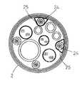
図4は、図1におけるIV−IV断面を示しており、可撓管2内に、処置具挿通チャンネル7、イメージガイドファイババンドル15、ライトガイドファイババンドル16、送気チューブ17、送水チューブ18及び噴射用送水チューブ19等が並んで挿通配置されている。
【0024】
そして、可撓性抑制用パイプ25は、可撓管2内におけるその可撓性抑制用パイプ25の周囲の空間形状に対応して、断面形状が楕円形に形成されている。このように、可撓性抑制用パイプ25の断面形状は周囲の空間形状に対応して任意の形状に形成することができ、例えば図5に示されるように、可撓管2の内周面に沿う面を有する異形の断面形状に形成してもよい。
【0025】
このようにして、各ワイヤガイド24に可撓性抑制用パイプ25が被嵌された可撓管2の基端寄りの部分では、可撓管2が曲げられる際に可撓性抑制用パイプ25が抵抗として作用して可撓性が抑制され、可撓管2の押し引き動作等が先端側に伝達され易い。
【0026】
そして、ワイヤガイド24に可撓性抑制用パイプ25が被嵌されていない可撓管2の先端寄りの部分は、可撓管2の曲げ動作に対して可撓性抑制用パイプ25が何らの影響を及ぼさないので、可撓性が大きく(即ち、柔軟性に富み)、体腔内の臓器形状に沿ってスムーズに変形する。
【0027】
ただし、単純にそのように構成すると、可撓管2の中間部分で可撓性が急激に変化して使い難かったり、その部分で急激に折れ曲がって破損し易くなる場合がある。
【0028】
そこで、この実施の形態においては、二本の可撓性抑制用パイプ25が、互いの先端位置をずらして各ワイヤガイド24に被嵌されており、それによって可撓管2の中間部における可撓性が滑らかに変化している。
【0029】
ただし、本発明はそれに限定されるものではなく、一本のワイヤガイド24だけに可撓性抑制用パイプ25を被嵌してもよく、三本以上のワイヤガイド24に可撓性抑制用パイプ25を被嵌してもよい。
【0030】
【発明の効果】
本発明によれば、ワイヤガイドの可撓管内に位置する部分のうち、可撓管の基端位置から中間位置までの範囲に、超弾性金属製のパイプ材からなる可撓性抑制用パイプを被嵌したことにより、可撓管の外皮の厚さや硬度を変化させることなく、可撓管で外装された部分の可撓性を途中で容易に製品毎のバラツキなく変化させることができ、可撓性抑制用パイプの断面形状をそのワイヤガイドの周囲の空間形状に対応した形状に形成したことにより、可撓管を太くすることなく可撓管内のスペースを有効利用することができる。
【図面の簡単な説明】
【図1】本発明の実施の形態の内視鏡の挿入部可撓管部分の軸線を含む面における断面図である。
【図2】内視鏡の外観略示図である。
【図3】本発明の実施の形態の図1におけるIII−III断面図である。
【図4】本発明の実施の形態の図1におけるIV−IV断面図である。
【図5】本発明の実施の形態の図1におけるIV−IV断面の他の実施例の断面図である。
【符号の説明】
2 可撓管
23 操作ワイヤ
24 ワイヤガイド
25 可撓性抑制用パイプ[0001]
BACKGROUND OF THE INVENTION
The present invention relates to an insertion portion of an endoscope that is inserted into a body cavity or the like.
[0002]
[Prior art]
The insertion part of the so-called flexible endoscope is constructed by inserting and placing a built-in object such as an optical fiber bundle into the exterior flexible tube, but the portion near the tip is relatively free along the shape of the organ in the body cavity. It is necessary to form it flexibly so that it bends, and to make the portion on the hand side stiff so that a delicate push-pull operation performed by the operator is transmitted to the tip side.
[0003]
Therefore, conventionally, the flexibility of the exterior flexible tube itself has been changed in the middle by changing the thickness, hardness, and the like of the outermost synthetic resin skin of the exterior flexible tube depending on the position.
[0004]
[Problems to be solved by the invention]
The outermost synthetic resin outer sheath of the outer flexible tube is generally formed by extrusion molding. However, in the manufacturing method in which the thickness and hardness of the outer flexible tube are changed halfway, it takes considerable time and cost to manufacture the outer flexible tube. . In addition, when the molding conditions are changed in the middle, there are many cases where variations in flexibility occur between products due to variations in the molding conditions.
[0005]
Accordingly, an object of the present invention is to provide an insertion portion of an endoscope in which the flexibility is easily and smoothly changed without changing the thickness or hardness of the outer skin of the flexible tube.
[0006]
[Means for Solving the Problems]
In order to achieve the above object, the insertion portion of the endoscope of the present invention has a plurality of wire guides composed of closely wound coil pipes for inserting and guiding an operation wire in a flexible tube covering the insertion portion. In the insertion portion of the endoscope that is inserted and arranged, the portion of the at least one wire guide of the plurality of wire guides that is located in the flexible tube, from the proximal end position to the intermediate position of the flexible tube. The range is characterized in that a flexible restraining pipe made of a superelastic alloy having a cross-sectional shape corresponding to the space shape around the wire guide is fitted.
[0007]
The flexibility suppressing pipe may be fitted to at least two wire guides of the plurality of wire guides while shifting the tip positions of the plurality of wire guides. It may be sandwiched and fixed between a pair of stopper members fixed to the guide.
[0008]
Moreover, the cross-sectional shape of the said flexibility suppression pipe may be elliptical, and may have a surface along the inner peripheral surface of the said flexible tube.
[0009]
DETAILED DESCRIPTION OF THE INVENTION
Embodiments of the present invention will be described with reference to the drawings.
FIG. 2 shows an endoscope. An insertion portion to be inserted into a body cavity or the like has a
[0010]
An
[0011]
The
[0012]
In addition, an air / water
[0013]
FIG. 1 shows a
[0014]
The
[0015]
The outer skin portion covering the
[0016]
A proximal
[0017]
The
[0018]
FIG. 1 shows two sets of four sets of
[0019]
A proximal end portion of the
[0020]
A
[0021]
The superelastic metal is, for example, a Ti-Ni (titanium-nickel) -based metal, and since the elastic limit of the metal is very large, the
[0022]
The
[0023]
4 shows a cross section taken along line IV-IV in FIG. 1. In the
[0024]
The
[0025]
In this way, in the portion near the base end of the
[0026]
The portion near the tip of the
[0027]
However, if it is simply configured as such, the flexibility may change abruptly at the intermediate portion of the
[0028]
Therefore, in this embodiment, the two
[0029]
However, the present invention is not limited thereto, and the
[0030]
【The invention's effect】
According to the present invention, a flexible restraining pipe made of a superelastic metal pipe material is provided in a range from a proximal end position to an intermediate position of a flexible tube in a portion located in the flexible tube of the wire guide. By fitting, the flexibility of the part covered with the flexible tube can be easily changed without any variation between products without changing the thickness and hardness of the outer shell of the flexible tube. By forming the cross-sectional shape of the flexibility-inhibiting pipe into a shape corresponding to the space shape around the wire guide, the space in the flexible tube can be effectively used without increasing the thickness of the flexible tube.
[Brief description of the drawings]
FIG. 1 is a cross-sectional view of a plane including an axis line of a flexible tube portion of an insertion portion of an endoscope according to an embodiment of the present invention.
FIG. 2 is a schematic external view of an endoscope.
3 is a cross-sectional view taken along the line III-III in FIG. 1 according to the embodiment of the present invention.
4 is a cross-sectional view taken along the line IV-IV in FIG. 1 according to the embodiment of the present invention.
5 is a cross-sectional view of another example of the IV-IV cross section in FIG. 1 according to the embodiment of the present invention.
[Explanation of symbols]
2
Claims (4)
Translated fromJapanese上記複数のワイヤガイドの中の少なくとも二つのワイヤガイドの上記可撓管内に位置する部分のうち、上記可撓管の基端位置から中間位置までの範囲に、各ワイヤガイドの周囲の空間形状に対応した断面形状の超弾性合金製の可撓性抑制用パイプが、互いの先端位置をずらして被嵌されていることを特徴とする内視鏡の挿入部。In the insertion portion of the endoscope in which a plurality of wire guides made of a tightly wound coil pipe for inserting and guiding an operation wire is inserted into a flexible tube covering the insertion portion,
Of the portion located at leasttwo wire guide of the flexible tube in the plurality of wire guides, the range to the intermediate position from the proximal position of said flexible tube, room shape aroundeach wire guide An insertion portion of an endoscope, characterized in that a flexible restraining pipe made of a superelastic alloy having a cross-sectional shape corresponding to the aboveis fitted by shifting the tip positions of the pipes.
Priority Applications (1)
| Application Number | Priority Date | Filing Date | Title |
|---|---|---|---|
| JP07296798AJP4070868B2 (en) | 1998-03-23 | 1998-03-23 | Endoscope insertion part |
Applications Claiming Priority (1)
| Application Number | Priority Date | Filing Date | Title |
|---|---|---|---|
| JP07296798AJP4070868B2 (en) | 1998-03-23 | 1998-03-23 | Endoscope insertion part |
Publications (2)
| Publication Number | Publication Date |
|---|---|
| JPH11267093A JPH11267093A (en) | 1999-10-05 |
| JP4070868B2true JP4070868B2 (en) | 2008-04-02 |
Family
ID=13504673
Family Applications (1)
| Application Number | Title | Priority Date | Filing Date |
|---|---|---|---|
| JP07296798AExpired - Fee RelatedJP4070868B2 (en) | 1998-03-23 | 1998-03-23 | Endoscope insertion part |
Country Status (1)
| Country | Link |
|---|---|
| JP (1) | JP4070868B2 (en) |
Families Citing this family (1)
| Publication number | Priority date | Publication date | Assignee | Title |
|---|---|---|---|---|
| JP4574806B2 (en)* | 2000-07-04 | 2010-11-04 | オリンパス株式会社 | Endoscope |
- 1998
- 1998-03-23JPJP07296798Apatent/JP4070868B2/ennot_activeExpired - Fee Related
Also Published As
| Publication number | Publication date |
|---|---|
| JPH11267093A (en) | 1999-10-05 |
Similar Documents
| Publication | Publication Date | Title |
|---|---|---|
| JP5228161B2 (en) | Endoscope bending device | |
| JP5390048B1 (en) | Endoscope system | |
| US20130331651A1 (en) | Flexible tube portion of endoscope and endoscope having this flexible tube portion | |
| JP4017734B2 (en) | Endoscope insertion part | |
| JP3814053B2 (en) | Endoscope bending device | |
| JPH08160315A (en) | Curved part of the endoscope | |
| JP4070868B2 (en) | Endoscope insertion part | |
| JP3992822B2 (en) | Endoscope insertion part | |
| JP5810037B2 (en) | Endoscope system | |
| JP4017735B2 (en) | Endoscope insertion part | |
| JP4021041B2 (en) | Endoscope insertion part | |
| JP4017736B2 (en) | Endoscope insertion part | |
| JP4895726B2 (en) | Flexible endoscope insertion part | |
| JP4504076B2 (en) | Endoscope | |
| JP3542835B2 (en) | Endoscope | |
| JP3845157B2 (en) | Endoscope insertion part | |
| JP2842616B2 (en) | Endoscope | |
| JP4206239B2 (en) | Endoscope optical fiber bundle protector | |
| JP4080601B2 (en) | Endoscope insertion part | |
| JP2001137180A (en) | Endoscope | |
| JP4447123B2 (en) | Endoscope connecting part | |
| JP2005230135A (en) | Endoscope flexible tube | |
| JPS632003Y2 (en) | ||
| JP3713110B2 (en) | Endoscope insertion part | |
| JPH0658456B2 (en) | Endoscope |
Legal Events
| Date | Code | Title | Description |
|---|---|---|---|
| A621 | Written request for application examination | Free format text:JAPANESE INTERMEDIATE CODE: A621 Effective date:20050126 | |
| A977 | Report on retrieval | Free format text:JAPANESE INTERMEDIATE CODE: A971007 Effective date:20070809 | |
| A131 | Notification of reasons for refusal | Free format text:JAPANESE INTERMEDIATE CODE: A131 Effective date:20070823 | |
| A521 | Written amendment | Free format text:JAPANESE INTERMEDIATE CODE: A523 Effective date:20071016 | |
| TRDD | Decision of grant or rejection written | ||
| A01 | Written decision to grant a patent or to grant a registration (utility model) | Free format text:JAPANESE INTERMEDIATE CODE: A01 Effective date:20080110 | |
| A61 | First payment of annual fees (during grant procedure) | Free format text:JAPANESE INTERMEDIATE CODE: A61 Effective date:20080116 | |
| R150 | Certificate of patent or registration of utility model | Free format text:JAPANESE INTERMEDIATE CODE: R150 | |
| FPAY | Renewal fee payment (event date is renewal date of database) | Free format text:PAYMENT UNTIL: 20110125 Year of fee payment:3 | |
| FPAY | Renewal fee payment (event date is renewal date of database) | Free format text:PAYMENT UNTIL: 20120125 Year of fee payment:4 | |
| FPAY | Renewal fee payment (event date is renewal date of database) | Free format text:PAYMENT UNTIL: 20130125 Year of fee payment:5 | |
| FPAY | Renewal fee payment (event date is renewal date of database) | Free format text:PAYMENT UNTIL: 20140125 Year of fee payment:6 | |
| LAPS | Cancellation because of no payment of annual fees |