JP4069450B2 - Air compressor and control method thereof - Google Patents
Air compressor and control method thereofDownload PDFInfo
- Publication number
- JP4069450B2 JP4069450B2JP2003178944AJP2003178944AJP4069450B2JP 4069450 B2JP4069450 B2JP 4069450B2JP 2003178944 AJP2003178944 AJP 2003178944AJP 2003178944 AJP2003178944 AJP 2003178944AJP 4069450 B2JP4069450 B2JP 4069450B2
- Authority
- JP
- Japan
- Prior art keywords
- pressure
- motor
- predetermined value
- tank
- change rate
- Prior art date
- Legal status (The legal status is an assumption and is not a legal conclusion. Google has not performed a legal analysis and makes no representation as to the accuracy of the status listed.)
- Expired - Fee Related
Links
Images


Classifications
- F—MECHANICAL ENGINEERING; LIGHTING; HEATING; WEAPONS; BLASTING
- F04—POSITIVE - DISPLACEMENT MACHINES FOR LIQUIDS; PUMPS FOR LIQUIDS OR ELASTIC FLUIDS
- F04B—POSITIVE-DISPLACEMENT MACHINES FOR LIQUIDS; PUMPS
- F04B49/00—Control, e.g. of pump delivery, or pump pressure of, or safety measures for, machines, pumps, or pumping installations, not otherwise provided for, or of interest apart from, groups F04B1/00 - F04B47/00
- F04B49/06—Control using electricity
Landscapes
- Engineering & Computer Science (AREA)
- Mechanical Engineering (AREA)
- General Engineering & Computer Science (AREA)
- Control Of Positive-Displacement Pumps (AREA)
Description
Translated fromJapanese【0001】
【発明の属する技術分野】
本発明は空気釘打機等の空気工具に用いられる圧縮空気を生成する空気圧縮機及びその制御方法に関するものである。
【0002】
【従来の技術】
一般に空気工具に用いられる空気圧縮機は、モータによって圧縮機本体のクランク軸を回転駆動し、このクランク軸の回転に応じてシリンダ内でピストンを往復動させることにより、吸気弁から吸い込んだ空気を圧縮するように構成されている。そして圧縮機本体で形成された圧縮空気は排気弁からパイプを通して空気タンクに吐出され、このタンク内に貯留される。空気工具はこのタンクに貯留された圧縮空気を用いて釘打等の作業を行うものである。
【0003】
このような空気圧縮機は建築現場に持ち運び野外で用いられたり、人家の密集している場所で使用されることが多いため、いろいろな観点から改良が求められている。本発明者等が現場で使用されている状況を調査した結果、ユーザから求められている要求、技術課題は次のような項目に整理することができる。
【0004】
(1)低騒音化
空気圧縮機はモータの回転をシリンダ内のピストンの往復動に変換する機構を有するためにモータの回転時にはかなりの騒音が発生するのを避けられない。またこの空気圧縮機からの圧縮空気を利用する釘打機なども作動時に作動音を出すため空気圧縮機自体の騒音と相まって建築現場の周囲にかなりの騒音を発生することとなる。特に人家の密集しているところで早朝や夕方以降に使用するときにはできるだけこの騒音を低減して欲しいという要求が大きい。
【0005】
(2)高パワー高効率化
空気圧縮機が用いられる現場は、必ずしも十分な電力環境にあるとは限らず、むしろ長いコードを用いて別の場所から電源電圧を供給するために十分な大きさの電圧が確保できなかったり、多数の工具を同時に使用するために電圧が変動するような環境で使用されることが多い。
【0006】
このため、空気圧縮機から高パワーの出力を発生できなくなることがあり、出力が不足した状態で例えば釘打機を使用するといわゆる釘浮き現象が生じ、十分に釘を加工材に打ち込むことができなくなるという問題を生ずる。
【0007】
また空気圧縮機は通常、空気タンクに26〜30kg/cm2の空気を貯留しているが、この空気は工具を使用していない期間にも少しずつリークすることを避けられず、使い方によっては効率の低下を招くという問題もある。
【0008】
(3)小型化可搬性の向上
空気工具用の空気圧縮機はまれに据置型として用いられるものもあるが、殆どは可搬型であり建築現場に持ち込んで使用される。従ってできるだけ小型で可搬性に優れていることも要求される。従って圧縮空気生成部及びこれを駆動する駆動部の構成を複雑にして可搬性を損なうことは極力避けなければならない。
【0009】
(4)長寿命化
冷蔵庫や空調機等に用いられるコンプレッサに比べ空気工具に用いられる空気圧縮機は寿命が短いという問題がある。これは過酷な環境で用いられるため、一面においては止むを得ないところでもあるが、できるだけ負荷の変動を抑制したり、無駄な圧縮空気の生成を抑えることにより更に寿命の長期化を図ることが望まれている。
【0010】
(5)温度上昇の抑制
シリンダ内のピストンの往復動及びピストンを駆動するモータに流れる電流により空気圧縮機はかなり高温になるのを避け難い。しかしながら圧縮機が高温になると損失が大きくなり高効率化を阻害する原因にもなる。従って空気圧縮機の温度上昇を可及的に抑制することも強く要望されている。
【0011】
【発明が解決しようとする課題】
以上述べたようないくつかの技術課題の中で本発明は、対処方法が相矛盾する上記(1)の低騒音化及び(2)の高パワー高効率化の問題を改善しようとするものである。
【0012】
具体的には本発明の目的は、人家のまばらな地域や、周囲の騒音が極めて大きい場所などで空気圧縮機の騒音が比較的問題にならないような環境下では、作業能率を重視し、常時高速高パワーで運転する空気圧縮機を提供することにある。
【0013】
本発明の他の目的は、人家の密集しているところで早朝や夕方以降に使用する場合など、低騒音を重視する環境下では、常時低速低騒音で運転する空気圧縮機を提供することにある。
【0014】
本発明の他の目的は、釘打機などの空気工具が発生する騒音はやむなしとして許容されるような環境下では、空気工具による空気消費量が少ないときはより低速で回転させることにより騒音が低く、コンクリート釘や太径の木材釘の連続打ちなどのように短時間にかなり多くの空気を消費するときには直ちに高速回転に移行し、パワーが不足することのない空気圧縮機を提供するにある。
【0015】
【課題を解決するための手段】
上記の目的を達成するために本発明は、圧縮空気を貯留するタンク部と、該タンク部に供給する圧縮空気を生成する圧縮空気生成部と、該圧縮空気生成部を駆動するためのモータを有する駆動部と、該駆動部を制御するための制御回路部と、上記タンク部の圧縮空気の圧力を検出する圧力センサを有し、上記制御回路部は、上記圧力センサからの検出信号に基づいて、前記モータの回転数を少なくとも3つのレベルの回転数N1,N2,N3(但しN1<N2<N3)で駆動制御する空気圧縮機において、前記制御回路部は、前記圧力センサからの検出信号に基づいて、タンク部内圧力の圧力変化率を求める手段を有し、上記圧力変化率が所定値より大きいときは、前記モータを回転数N2又はN3で回転し、上記圧力変化率が所定値より小さいときは、前記タンク部内の圧力Pに応じて前記回転数N1,N2,N3の1つを選択して前記モータを回転するオートモードの制御手段を備えたことに一つの特徴を有する。
【0016】
本発明の他の特徴は、前記制御回路部は、前記タンク部内圧力の圧力変化率が所定値より大きいときは、前記モータを回転数N1で回転し、前記圧力変化率が所定値より小さいときは、前記タンク部内の圧力が第1の所定値PHより大きいとき前記モータの回転を停止し、前記タンク部内の圧力が上記圧力PHよりも低い第2の所定値PLより小さくなったとき、前記モータを回転数N1で回転する静音モードの制御手段を備えたことにある。
【0017】
本発明の他の特徴は、前記制御回路部は、前記タンク部内圧力の圧力変化率が所定値より大きいときは、前記モータを回転数N2又はN3で回転し、前記圧力変化率が所定値より小さいときは、前記タンク部内の圧力が第1の所定値PHより大きいとき前記モータの回転を停止し、前記タンク部内の圧力が上記圧力PHよりも低い第2の所定値PLより小さくなったとき、前記モータを回転数N2又はN3で回転するパワーモードの制御手段を備えたことにある。
【0018】
本発明の他の特徴は、上記モータの温度を検出するための温度センサと、上記駆動部の電源電圧を検出する電圧センサと、上記駆動部の負荷電流を検出する電流センサの少なくとも1つのセンサを有し、パワーモード又はオートモードにおいて、前記圧力変化率が所定値より大きいときは、上記電圧センサの出力が所定値よりも小さい場合及び温度センサ、電流センサの出力が所定値よりも大きい場合は、回転数N2を選択して前記モータを回転する制御手段を備えたことにある。
本発明の他の特徴及び利点は、以下の説明より一層明確に理解される。
【0030】
【発明の実施の形態】
以下本発明の実施の形態について詳細に説明する。
本発明にかかる空気圧縮機は図1の概念図に示すように圧縮空気を貯留するタンク部10、圧縮空気を生成する圧縮空気生成部20、該圧縮空気生成部20を駆動するための駆動部30及び該駆動部30を制御するための制御回路部40より構成されている。
【0031】
(1)タンク部10
タンク部10は図2に示すように高圧圧縮空気を貯留するための空気タンク10Aを有し、圧縮部20Aの吐出口に連結されたパイプ21を通して例えば20〜30kg/cm2の高圧圧縮空気が供給される。
【0032】
上記空気タンク10Aには通常複数個の圧縮空気取出口18、19が設けられており、本実施形態では低圧の圧縮空気を取り出すための取出口18と、高圧の圧縮空気を取り出すための取出口19が取り付けられている例が示されている。勿論本発明がこれに限定されるものではない。
【0033】
低圧用圧縮空気取出口18は減圧弁12を介して低圧用カプラ14に接続されている。減圧弁12はその入口側の圧縮空気の圧力に拘らず出口側の圧縮空気の最高圧力が定められており、本実施形態ではその最高圧力が7〜10kg/cm2の範囲の所定値に選定されている。従って減圧弁12の出口側からは空気タンク10Aの圧力に拘らず上記の最高圧力以下の圧力の圧縮空気が得られる。
【0034】
減圧弁12の出力側の圧縮空気は低圧用カプラ14を介して図1に示した低圧用の空気工具51に供給される。
【0035】
一方高圧用圧縮空気取出口19は減圧弁13を介して高圧用カプラ15に接続されている。減圧弁13はその入口側の圧縮空気の圧力に拘らず出口側の圧縮空気の最高圧力が定められており、本実施形態ではその最高圧力が10〜30kg/cm2の範囲の所定値に選定されている。従って減圧弁13の出口側からはこの最高圧力以下の圧力の圧縮空気が得られる。減圧弁13の出力側の圧縮空気は高圧用カプラ15を介して図1に示した高圧用の空気工具52に供給される。
【0036】
減圧弁12及び13には低圧用圧力計16及び高圧用圧力計17がそれぞれ取り付けられており、減圧弁12及び13の出口側の圧縮空気の圧力をモニタできるように構成されている。また低圧用カプラ14と高圧用カプラ15は寸法が異なり互換性がないので低圧用カプラ14には高圧用の空気工具52を接続することができず、また高圧用カプラ15には低圧用の空気工具51は接続することができないように構成されている。このような構成は既に本願発明と同一の出願人により特開平4−296505に出願されている。
【0037】
上記空気タンク10Aの一部には圧力センサ11が取り付けられており、タンク10A内の圧縮空気の圧力が検出される。この検出信号は制御部40に供給され、後述のモータの制御に用いられる。また空気タンク10Aの一部には安全弁10Bが取り付けられており、空気タンク10A内の圧力が異常に高くなったときにその空気の一部を外部に逃がして安全を確保している。
【0038】
(2)圧縮空気生成部20
圧縮空気生成部20はシリンダ内にピストンを往復運動させ、シリンダの吸気弁からシリンダ内に引き込まれた空気を圧縮することにより圧縮空気を生成するもので、このように圧縮機自体は既に公知である。例えば本願発明と同一の出願人により出願されている特開平11−280653にはモータの回転を、ロータ軸の先端に設けたピニオン及びこれとかみ合うギアを介して出力軸に伝達し、出力軸の運動によりピストンを往復動させる機構が開示されている。
【0039】
ピストンがシリンダ内を往復動するとシリンダヘッドに設けられた吸気弁より引き込まれた空気が圧縮加工され、所定の圧力に達するとシリンダヘッドに設けられた排気弁から圧縮空気が得られる。この圧縮空気は図2のパイプ21を通して前述の空気タンク10Aに供給される。
【0040】
(3)駆動部30
駆動部30は上述のピストンを往復運動させるための駆動力を発生させるもので図3に示すようにモータ33とモータ駆動回路32及び電源回路31より構成されている。電源回路31は100Vの交流電源310の電圧を整流するための整流回路313及び整流された電圧を平滑し、昇圧した後定電圧にするための平滑・昇圧・定電圧回路314を含んでいる。
【0041】
また必要に応じて電源310の両端の電圧を検出するための電圧検出器311及び電源310に流れる電流を検出するための電流検出器312を設け、各検出器311及び312の出力信号が後述の制御部40に供給される。これらの検出器311、312は例えば、電源310のブレーカ(図示せず)が切れない範囲で極めて短時間の間、モータ33を超高速回転するような場合の制御に用いられるが、本実施形態の制御には直接関係しないため詳細な説明は省略する。また定電圧回路314により一定の電圧を得るためにも制御部40が関与するが定電圧回路の構成自体は公知であるのでここでは詳しく述べない。
【0042】
モータ駆動回路32は直流電圧からU相、V相、W相の3相のパルス電圧を発生するためのスイッチング用トランジスタ321〜326を含んでいる。各トランジスタ321〜326のオン・オフは制御部40によって制御される。各トランジスタ321〜326に供給されるパルス信号の周波数を制御することによって、モータの回転数を制御している。
【0043】
一例として、モータ33の回転数Nは、0rpm、1200rpm、2400rpm、3600rpmのように、基準値Nの整数n倍に多段階に設定され、この中から選択された回転数で駆動するように制御される。
【0044】
各スイッチング用トランジスタ321〜326には並列にダイオードが接続されているが、これはモータ33のステータ33Aに発生する逆起電力によりトランジスタ321〜326が破壊するのを防止するためのものである。
【0045】
次にモータ33はステータ33Aとロータ33Bを含む。ステータ33AにはU相、V相、W相の巻線331、332、333が形成されており、これら巻線331〜333に流れる電流によって回転磁界が形成される。
【0046】
ロータ33Bは本実施形態では永久磁石から構成され、ステータ33Aの巻線331〜333に流れる電流により形成される回転磁界により回転する。このロータ33Bの回転力が前述の圧力空気生成部20(図1)のピストンを動作させる駆動力になる。
【0047】
モータ33にはステータ33Aの巻線の温度を検出するための温度検出回路334が設けられ、その検出信号が制御部40に供給される。また必要に応じてロータ33Bの回転数を検出する回転数検出回路335が設けられ、その検出信号が制御部40に供給される。
【0048】
(4)制御回路部40
制御回路部40は図1に示すように中央処理ユニット(以下CPUと略す)
41、ランダムアクセスメモリ(以下RAMと略す)42、リードオンリメモリ(以下ROMと略す)43、及び運転モード選択スイッチ46を含む。
【0049】
前述の圧力センサ11の検出信号及び温度検出回路334の検出信号はインターフェース回路(以下I/F回路と略す)44、45を介してCPU41に供給される。またCPUからの指令信号はI/F回路45を介して駆動部30のモータ駆動回路32に供給されスイッチング用トランジスタ321〜326(図3)の制御が行われる。
【0050】
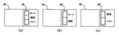
運転モード選択スイッチ46は、図14の(a)に示すようにパワーモード、静音モード、オートモードの三つの運転モードが選択できるように構成されている。本実施形態では選択できるモードを三つにしたが本発明はこれに限定されるものではなく、例えば図14の(b)のようにオートモードと静音モードの二つの場合、あるいは図14の(c)のように静音モードとパワーモードの二つの場合も含まれる。モードの数は使用環境に応じて適宜選択される。
【0051】
ROM43には図4、図5、図6、図7に示すようなモード選択及びモータの制御プログラムが格納されており、RAM42はそのプログラムの実行に必要なデータや演算結果を一時格納するために用いられる。
【0052】
(5)制御用のプログラム
(5.1)モード選択
図4は本発明の制御回路部40のROM43に格納されているモード選択プログラムのフローチャートを示す。
図4のステップ70においては図14に示した運転モードスイッチ46が押下され運転モードが選択される。ステップ71では選択されたモードがオートモードか否かが判定される。この判定が肯定(YES)のときは図5のステップ100のオートモードプログラムにジャンプし、否定(NO)のときはステップ72に進む。
【0053】
次にステップ72において運転モード選択スイッチ46が静音モードを選択しているか否かが判定され、その判定が肯定(YES)のときは図6のステップ200の静音モードプログラムにジャンプする。また判定が否定(NO)のときはステップ73に進む。
【0054】
次にステップ73において運転モード選択スイッチ46がパワーモードを選択しているか否かが判定され、その判定が肯定(YES)のときは図7のステップ300のパワーモードプログラムにジャンプする。ステップ71、72、73の各ステップの判定が全て否定(NO)の場合は、運転モードが選択されるまでステップ71、72、73の実行を繰り返す。
【0055】
(5.2)オートモード
図5は本発明の制御回路部40のROM43に格納されているオートモード
プログラムのフローチャートを示す。
図5では、まずステップ101において初期設定を行い、モータ33の回転数NをN2=2400rpmに設定する。また、圧力タンク10Aの圧力センサ11により検出された信号を制御回路部40に取り込むためのサンプリング周期ΔTは二種類として短周期ΔT1は0.05秒、長周期ΔT2は5秒とする。即ちi=0、1、2、3…100としてP(i−1)とP(i)との差から0.05秒に1回タンク内圧力の変化を検出すると共に、P(i=0)とP(i=100)との差から5秒間に1回圧力変化を検出する。
【0056】
本実施形態では短時間の周期を0.05秒としたが、これは1回に大量の空気を消費する釘打機等が作動したときに生ずるタンク内圧力のリップルを検出するために設定された周期であり、使用される空気工具等にも依存する値であるから本発明が必ずしもこの数値に限定されるものでないことはもちろんである。同様に長時間の周期の5秒は、空気工具の使用状態によるタンク内圧力変化を検出するために設定された周期であるから一つの例示であってこの数値に限定される訳ではない。
【0057】
次にステップ104に進み、オートモードが選択され続けているかどうか確認する。判定が否定(NO)、即ちオートモードが選択されてない場合は図4におけるステップ70のモード選択へジャンプする。判定が肯定(YES)、即ちオートモードが選択され続けている場合は次のステップ105に進み、本発明の空気圧縮機の制御に用いられる回転数のデータを記憶する。この実施形態ではモータ33の回転数NをN0(=0rpm)、N1(1200rpm)、N2(2400rpm)、N3(3600rpm)の4段階に制御するので、それぞれN0、N1、N2、N3の値がRAM42の適当な領域に記憶される。モータ33の速度を更に多段階に設定することは容易であるが、少なくとも3段階以上であることが望ましい。
【0058】
次にステップ106に進みタンク10Aの圧縮空気の圧力P(i)を測定し、これを記憶する。ステップ108においては測定した圧力P(i)が30kg/cm2より大きいか否かを判定し、その判定が肯定(YES)のときはステップ107に進みモータ33の回転数NをN0(0rpm)に設定する。即ち本実施形態ではタンク10Aの圧力を20kg/cm2〜30kg/cm2に維持するように制御する例を示しており、従ってタンク内圧力が30kg/cm2を超えるとモータ33の回転が止められる。
【0059】
ステップ108における判定が否定(NO)のときはステップ109に進み、(i+1)を(i)と代入され、ステップ110においてタンク内圧力P(i)が測定され、その値が先のP(i−1)と共に記憶される。更にステップ111においてCPU41により短時間周期ΔT1における圧力変化率ΔP1/ΔT1(=(P(i)−P(i−1))/0.05)が算出される。
【0060】
更にステップ112では上述の短周期の圧力変化率ΔP1/ΔT1が所定値より小さいか否かが判定される。この判定は圧力タンク10Aに接続された空気工具が連続釘打ちなどのように短時間に多量の空気を消費する態様で作動しているか否かを判定するもので、本実施形態では所定値を−1として設定されている。連続釘打ちをすると、タンク内圧力が脈動し、圧力変化のリップルが大きくなる。そしてΔT1におけるΔP1の減少が(−1)より大きい(つまりΔP1/ΔT1<−1)ときにはそのリップルの大きさより判断して連続釘打ち等の態様で空気工具が使用されていると判定してステップ126に進む。
【0061】
ステップ126では電源回路31(図3)における電源310の電圧(V)が検出器311によって検出され、更にステップ127でその値が所定値より小さいか否かが判定される。本実施形態では上記の所定値は90Vに設定されている。即ち空気工具による空気消費量が大きいときには直ちにモータ33の回転数を上昇して圧縮空気の生成量を増大することが望ましいが、例えばタンク10Aに他の空気工具も接続され使用されているような場合は、負荷が大きくなり電源回路31(図3)のブレーカ(図示せず)が作動してしまうことがあるので、これを避けるために電源電圧Vの大きさが所定値(90V)より小さいか否かをステップ127で判定しているのである。このステップ127の判定が肯定(YES)のとき、つまり通常100Vである電源電圧が90V以下に低下しているということは、他の空気工具等の使用により電源310の負荷が相当大きいと判断してステップ133に進みモータ33の回転数NをN2(=2400rpm)に維持する。
【0062】
電源310の電圧が90V以上あるときは次にステップ128に進み、電流検出器312によって電源回路31に流れる負荷電流Iが検出される。そしてステップ129において測定された電流Iが所定値より大きいか否かが判定される。本実施形態では上記の所定値が30Aに設定されている。この判定が肯定(YES)のときは、モータ33の回転数Nを現状以上に上昇すると、モータ33の巻線温度が過度に上昇したり、電源310のブレーカが切断する可能性があると判定して、やはりステップ133に進みモータ33の回転数をN2(=2400rpm)に維持する。
【0063】
ステップ129の判定が否定(NO)のときはステップ130に進みモータ
33におけるステータ331の巻線温度大が測定され、更にステップ131においてこの巻線温度が所定値より大きいか否かが判定される。本実施形態では上記の所定値は120℃に設定されている。またこの実施形態ではモータ33の巻線温度を測定しているが、他の部所の温度を測定してもよい。モータ巻線の温度が120℃以上の状態でモータ33の回転数を更に増加するとモータ33の温度が過度に上昇し、モータの運転に支障をきたすおそれがあると共に、過度の温度上昇により圧縮空気生成部20の圧縮空気生成効率を著しく低下させるおそれがあるのでステップ131の判定が肯定(YES)のときはやはりステップ133に進み、モータ33の回転数NをN2(=2400rpm)に維持する。
【0064】
ステップ131の判定が否定(NO)のときはステップ132に進み、モータ33の回転数NがN3(=3600rpm)に設定される。
次にステップ134では再びi=0としてステップ135でタンク10Aの内圧P(i)が30kg/cm2より大きいか否かが判定される。この判定が肯定(YES)の場合はステップ107に戻ってモータ33の回転を止める。ステップ135の判定が否定(NO)の場合はステップ136でi+1をiに置き換える演算を行い、ステップ137ではiが100になったか否か、つまり5秒経過したか否かが判定される。この判定が肯定(YES)の場合はi=0と置き(ステップ102)、ステップ104に戻る。上記のステップ135〜137は、0.05秒毎にモータ33の回転数がN2とN3に切り替わると不快感を覚えるので5秒間は同一の回転数を維持するように制御するためである。
【0065】
一方、前述のステップ112における判定が否定(NO)の場合、つまり短時間(0.05秒)におけるタンク内の圧力変化率が所定値より小さい場合はステップ113に進み、時間がΔT2秒(=5秒)経過したか否か判定される。この判定が否定(NO)の場合はステップ108に戻るが、肯定(YES)の場合はステップ114に進み、長時間(5秒)における圧力変化率ΔP2/ΔT2(=(P(i=100)−P(i=0))/5)の算出が行われる。
【0066】
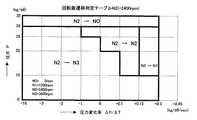
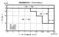
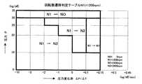
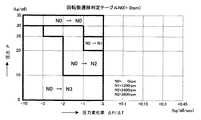
次にステップ115では回転数遷移テーブルの選定が行われる。制御回路部
40のRAM42には予め図10、図11、図12、図13に示すような4種類の回転数遷移判定テーブルが格納されている。モータ33の現在の回転数Nが初期値のN2(=2400rpm)のときは図10のテーブルが選択される。また現在の回転数NがN3(=3600rpm)のときは図11のテーブルが選択される。同様にして回転数NがN1のときは図12のテーブルが、NがN0のときは図13のテーブルが選択される。これらのテーブルは何れも縦軸にタンク内の圧力P、横軸にタンク内圧力の圧力変化率ΔP/ΔTをとってあり、それらの値からモータ33の回転数を決定するために用いられる。
【0067】
図10を例にとって説明すると、まずタンク内の圧力Pが30kg/cm2を超えた場合はΔP/ΔTの値に拘らず回転数をN0にする。つまりモータを停止する。これはタンク内の圧力を常に26kg/cm2から30kg/cm2の範囲に保持するように制御しているのであるから当然である。
【0068】
圧力変化率ΔP/ΔTが負であるということは、タンク10Aに供給される圧縮空気よりも消費される圧縮空気の方が多いことを意味するからモータ33の現在の回転数N2(=2400rpm)をこれよりも高い回転数N3(=3600rpm)に切換える制御が行われる。特に、空気工具51、52(図1)がフル稼働しているような場合は圧縮空気の消費量が多くタンク10A内の圧力が急速に低下するおそれがあるので、この例ではΔP/ΔTが−1kg/cm2以上のときはタンク内の圧力Pが30kg/cm2以下にあれば直ちに回転数をN3に切換える。但し圧力変化率ΔP/ΔTが0〜−1kg/cm2と比較的小さい場合は、タンク10Aの圧力Pが26kg/cm2以上あれば引き続きN2の回転数でモータ33を運転し、タンク10Aの圧力Pが26kg/cm2より下がったときにN3に切換える。またΔP/ΔTが0〜+1kg/cm2の範囲にあるとき、即ち圧縮空気の消費よりも供給の方が若干多いときにはタンク10A内の圧力Pが20kg/cm2以上あれば引き続きN2で運転し、これより低下したときにN3に切換える。
【0069】
ΔP/ΔTの値が+0.1〜+0.15kg/cm2の範囲にあるときは、タンク10A内の圧縮空気の量が増加しつつあることを示しているからタンクPが内圧力10kg/cm2以上あればN2で回転し続け、10kg/cm2より低下したらN3に切換える。ΔP/ΔTが+0.15〜+0.3kg/cm2と大きくなると、急速にタンク内圧力Pの増加が予測されるのでタンク内の圧力が10kg/cm2以上あればモータの回転数を現在のN2からN1に低下させるように制御する。
【0070】
以上の説明は現在運転中のモータ33の回転数をN2として、これからN0、N3、N1に遷移する場合であるが、現在の回転数がN3、N1、N0の場合には図11、図12、図13のように異なったパターンにより遷移するように制御される。
【0071】
次にステップ116において5秒経過後のタンク内圧力P(i=100)及び5秒間における圧力変化率ΔP2/ΔT2からモータ33の次の回転数を上記の選択されたテーブルから検索して決定する。この結果、選択された回転数NがN3(=3600rpm)の場合は(ステップ118)、直ちにN3に切換えるのではなく次のステップ118〜123の判定により電源電圧Vが90V以上、且つ負荷電流Iが30A以下、且つモータ巻線温度大が120℃以下か否かが判定される。このステップ118〜123の機能は前述のステップ126〜131と同じであるので詳細な説明は省略するが、要するに電源ブレーカ(図示せず)の作動を防止し、且つモータ33の過昇温防止のためのフローである。
【0072】
これらのステップ118〜123の判定の結果、モータ33の回転数Nを最高速の3600rpmに切換えてもブレーカが切断したりモータ33の温度が過度に上昇しないと判断された場合はステップ124に進みN=N3(=3600rpm)にモータ速度が設定される。しかしその条件を満たさない場合はステップ125に進みモータ33の回転数NはN2に維持される。即ち本発明においては短時間(0.05秒)の圧力変化率が大きい場合及び長時間(5秒)の圧力変化率が大きい場合には空気消費量が多くなると予測してモータ33の回転数をN3に上昇させるが、モータ33の負荷がすでに相当重く、ブレーカが切断するおそれがあったりモータ巻線温度が過度に上昇するおそれがある場合はN2に維持するという制御が行われる。
【0073】
(5.3)静音モード
図6は本発明の制御回路部40のROM43に格納されている静音モードプログラムのフローチャートを示す。静音モードではモータ33は停止しているか最低速N1=1200rpmで回転しているかのどちらかである。
【0074】
図6では、まずステップ201において初期設定を行い、モータ33の回転数NをN1=1200rpmに設定する。また、圧力タンク10Aの圧力センサ11により検出された信号を制御回路部40に取り込むためのサンプリング周期ΔT1は0.05秒とする。即ちi=0、1、2、3…としてP(i−1)とP(i)との差から0.05秒に1回タンク内圧力の変化を検出する。本実施形態では周期を0.05秒としたが、前述のようにこれは1回に大量の空気を消費する釘打機等が作動したときに生ずるタンク内圧力のリップルを検出するために設定された周期であり、使用される空気工具等にも依存する値であるから本発明は必ずしもこの数値に限定されるものでない。
【0075】
次にステップ204に進み、静音モードが選択され続けているかどうか確認する。判定が否定(NO)、即ち静音モードが選択されてない場合は図4ステップ70のモード選択へジャンプする。判定が肯定(YES)、即ち静音モードが選択され続けている場合は次のステップ205に進み、タンク10Aの圧縮空気の圧力P(i)を測定し、これを記憶する。ステップ206においては測定した圧力P(i)が30kg/cm2より大きいか否かを判定し、その判定が肯定(YES)のときはステップ203に進みモータ33の回転数NをN0(0rpm)に設定する。即ち本実施形態ではタンク10Aの圧力を20kg/cm2〜30kg/cm2に維持するように制御する例を示しており、従ってタンク内圧力が30kg/cm2を超えるとモータ33の回転が止められる。
【0076】
ステップ206における判定が否定(NO)のときはステップ207に進み、(i+1)を(i)と代入され、ステップ208においてタンク内圧力P(i)が測定され、その値が先のP(i−1)と共に記憶される。更にステップ209においてCPU41により周期ΔT1における圧力変化率ΔP1/ΔT1(=(P(i)−P(i−1)/0.05)が算出される。
【0077】
更にステップ210では上述の短周期の圧力変化率ΔP1/ΔT1が所定値より小さいか否かが判定される。この判定は圧力タンク10Aに接続された空気工具が連続釘打ちなどのように短時間に多量の空気を消費する態様で作動しているか否かを判定するもので、本実施形態では所定値を−1として設定されている。連続釘打ちをすると、タンク内圧力が脈動し、圧力変化のリップルが大きくなる。そしてΔT1におけるΔP1の減少が(−1)より大きい(つまりΔP1/ΔT1<−1)ときにはそのリップルの大きさより判断して連続釘打ち等の態様で空気工具が使用されていると判定してステップ212に進みモータ33をN1=1200rpmで回転させる。
【0078】
一方、前述のステップ210における判定が否定(NO)の場合、つまり短時間(0.05秒)におけるタンク内の圧力変化率が所定値より小さい場合はステップ211に進む。ステップ211では、測定した圧力P(i)が26kg/cm2より大きいか否かを判定し、その判定が肯定(YES)のときはステップ206に戻る。ステップ211における判定が否定(NO)の場合、即ちタンク内圧が26kg/cm2以下の場合はステップ212に進みモータ33をN1=1200rpmで回転させる。要するに、ステップ206〜212においては、リップルが所定値よりも大きい場合は圧力が26kg/cm2まで低下するのをまたずに、リップル検出後直ちにモータ33を起動し内圧低下を押さえるように動作する。
【0079】
次にステップ213に進み、圧力P(i)を測定する。測定した圧力P(i)が30kg/cm2より大きいか否かを判定し、その判定が肯定(YES)のときはステップ203に進みモータ33の回転数NをN0(0rpm)に設定する。圧力が30kg/cm2以下の場合は圧力が30kg/cm2になるまで圧力測定を繰り返す。
【0080】
(5.4)パワーモード
図7は本発明の制御回路部40のROM43に格納されているパワーモードプログラムのフローチャートを示す。パワーモードではモータ33は高速N3=3600rpmか中速N2=2400rpmで回転する。
【0081】
図7では、まずステップ301において初期設定を行い、モータ33の回転数NをN2=2400rpmに設定する。また、圧力タンク10Aの圧力センサ11により検出された信号を制御回路部40に取り込むためのサンプリング周期ΔT1は0.05秒とする。即ちi=0、1、2、3…としてP(i−1)とP(i)との差から0.05秒に1回タンク内圧力の変化を検出する。本実施形態では周期を0.05秒としたが、本発明が必ずしもこの数値に限定されるものでないことは勿論である。
【0082】
次にステップ304に進み、パワーモードが選択され続けているかどうか確認する。判定が否定(NO)、即ちパワーモードが選択されてない場合は図4におけるステップ70のモード選択へジャンプする。判定が肯定(YES)、即ちパワーモードが選択され続けている場合は次のステップ305に進み、タンク10Aの圧縮空気の圧力P(i)を測定し、これを記憶する。ステップ306においては測定した圧力P(i)が30kg/cm2より大きいか否かを判定し、その判定が肯定(YES)のときはステップ324に進みモータ33の回転数NをN0(0rpm)に設定する。即ち本実施形態ではタンク10Aの圧力を20kg/cm2〜30kg/cm2に維持するように制御する例を示しており、従ってタンク内圧力が30kg/cm2を超えるとモータ33の回転が止められる。
【0083】
ステップ306における判定が否定(NO)のときはステップ307に進み、(i+1)を(i)と代入され、ステップ308においてタンク内圧力P(i)が測定され、その値が先のP(i−1)と共に記憶される。更にステップ309においてCPU41により周期ΔT1における圧力変化率ΔP1/ΔT1(=(P(i)−P(i−1))/0.05)が算出される。
【0084】
更にステップ310では上述の短周期の圧力変化率ΔP1/ΔT1が所定値より小さいか否かが判定される。この判定は圧力タンク10Aに接続された空気工具が連続釘打ちなどのように短時間に多量の空気を消費する態様で作動しているか否かを判定するもので、本実施形態では所定値を−1として設定されている。連続釘打ちをすると、タンク内圧力が脈動し、圧力変化のリップルが大きくなる。そしてΔT1におけるΔP1の減少が(−1)より大きい(つまりΔP1/ΔT1<−1)ときにはそのリップルの大きさより判断して連続釘打ち等の態様で空気工具が使用されていると判定してステップ312に進む。
【0085】
ステップ312では電源回路31(図3)における電源310の電圧(V)が検出器311によって検出され、更にステップ313でその値が所定値より小さいか否かが判定される。本実施形態では上記の所定値は90Vに設定されている。即ち空気工具による空気消費量が大きいときには直ちにモータ33の回転数を上昇して圧縮空気の生成量を増大することが望ましいが、例えばタンク10Aに他の空気工具も接続され使用されているような場合は、負荷が大きくなり電源回路31(図3)のブレーカ(図示せず)が作動してしまうことがあるので、これを避けるために電源電圧Vの大きさが所定値(90V)より小さいか否かをステップ313で判定しているのである。このステップ313の判定が肯定(YES)のとき、つまり通常100Vである電源電圧が90V以下に低下しているということは、他の空気工具等の使用により電源310の負荷が相当大きいと判断してステップ319に進みモータ33の回転数NをN2(=2400rpm)に維持する。
【0086】
電源310の電圧が90V以上あるときは次にステップ314に進み、電流検出器312によって電源回路31に流れる負荷電流Iが検出される。そしてステップ315において測定された電流Iが所定値より大きいか否かが判定される。本実施形態では上記の所定値が30Aに設定されている。この判定が肯定(YES)のときは、モータ33の回転数Nを現状以上に上昇すると、モータ33の巻線温度が過度に上昇したり、電源310のブレーカが切断する可能性があると判定して、やはりステップ319に進みモータ33の回転数をN2(=2400rpm)に維持する。
【0087】
ステップ315の判定が否定(NO)のときはステップ316に進みモータ
33におけるステータ331の巻線温度大が測定され、更にステップ317においてこの巻線温度が所定値より大きいか否かが判定される。本実施形態では上記の所定値は120℃に設定されている。またこの実施形態ではモータ33の巻線温度を測定しているが、他の部所の温度を測定してもよい。モータ巻線の温度が120℃以上の状態でモータ33の回転数を更に増加するとモータ33の温度が過度に上昇し、モータの運転に支障をきたすおそれがあると共に、過度の温度上昇により圧縮空気生成部20の圧縮空気生成効率を著しく低下させるおそれがあるのでステップ317の判定が肯定(YES)のときはやはりステップ319に進み、モータ33の回転数NをN2(=2400rpm)に維持する。
【0088】
ステップ317の判定が否定(NO)のときはステップ318に進み、モータ33の回転数NがN3(=3600rpm)に設定される。
【0089】
次にステップ320では再びi=0としてステップ321でタンク10Aの内圧P(i)が30kg/cm2より大きいか否かが判定される。この判定が肯定(YES)の場合はステップ324に戻ってモータ33の回転を止める。ステップ321の判定が否定(NO)の場合はステップ322でi+1をiに置き換える演算を行い、ステップ323ではiが100になったか否か、つまり5秒経過したか否かが判定される。この判定が肯定(YES)の場合はi=0と置き(ステップ102)、ステップ104に戻る。上記のステップ135〜137は、0.05秒毎にモータ33の回転数がN2とN3に切り替わると不快感を覚えるので5秒間は同一の回転数を維持するように制御するためである。
【0090】
一方、前述のステップ310における判定が否定(NO)の場合、つまり短時間(0.05秒)におけるタンク内の圧力変化率が所定値より小さい場合はステップ311に進む。ステップ311では、測定した圧力P(i)が26kg/cm2より大きいか否かを判定し、その判定が肯定(YES)のときはステップ306に戻る。ステップ311における判定が否定(NO)の場合、即ちタンク内圧が26kg/cm2 以下の場合はやはりステップ312に進む。要するに、ステップ306〜312においては、リップルが所定値よりも大きい場合は圧力が26kg/cm2 まで低下するのをまたずに、リップル検出後ただちにモータ33を起動し内圧低下を押さえるように動作する。
【0091】
(6)動作
次に本発明の動作について説明する。
図8は回転数の遷移がない場合のタンク内圧力Pの変化カーブを示す。これは、例えば空気工具が全く使用されない状態であり、曲線aはモータ33を3600rpmで回転したとき、bは2400rpm、cは1200rpmで回転したときの変化を示す。回転数の設定値が2400rpmとすると、最初モータのスイッチを入れ、曲線bに従ってタンク内の圧力が上昇し、3分程度経過すると30kg/cm2に達してモータの運転が停止する。そのまま放置しておくと圧力タンク内の圧縮空気はエア漏れのために少しずつリークして減少し、26kg/cm2まで低下すると再びモータの運転が開始される。曲線a及びcの場合も同様に30kg/cm2でモータがオフ、26kg/cm2でオンとなるようなオン・オフ制御動作をする。
【0092】
次に本発明空気圧縮機がオートモードで運転するときの動作を図9を用いて説明する。
【0093】
図9は横軸に時間、縦軸にタンク内の圧縮空気の圧力をとったもので曲線(a)及び(b)はタンク内圧力のリップル検出をしなかった場合、つまり長時間(5秒間)毎の圧力変化率に応じて制御はするが短時間(0・05秒)毎の圧力変化率に応じた制御を行わない場合、曲線(a´)、(b´)はタンク内圧力のリップル検出を行い、上記の両圧力変化率に応じて制御を行った場合を示す。
【0094】
曲線(a)は、時間T=0まではタンク内の圧力Pが29kg/cm2で圧縮空気の消費はなく、モータ33が停止している状態を示している。時間T=0より例えば釘打機による連続釘打ちが始まると、大量に空気が消費されるためタンク内圧力は脈動しながら急速に低下する。T=5秒後に5秒間の圧力変化率ΔP2/ΔT2を行い、この値ΔP2/ΔT2が−1.7であるために回転数遷移判定テーブルから中速回転N2=2400rpmを選択する。従ってT=0秒からT=5秒まではN0、T=5秒以降はN2で回転する。
【0095】
曲線(a´)はリップル検出(ΔP1/ΔT1)を行う場合であり、時間T=0まではタンク内圧力Pは29kg/cm2でモータ33は停止している。時間T=0から連続釘打ちが始まると、上記と同様に最初はタンク内圧力は脈動しながら低下する。しかしΔT1=0.05秒後にはリップルの圧力検出率(=ΔP1/ΔT1)が算出されΔP1/ΔT1=−5<−1であるためリップル大と判断される。そして電源電圧Vが90V以上、負荷電流Iが30A以下で且つモータ巻線温度tが120℃以下なので直ちに高速回転N3=3600rpmに移行する。従ってΔT1=0.05秒後は、モータ33はN3=3600rpmの高速で回転するために曲線(a´)のようにタンク内圧力の低下は抑制され、29kg/cm2に近い状態が維持される。
【0096】
一方曲線(b)は、時間T=0まではタンク内圧力Pが26kg/cm2以下で空気の消費がなく、モータ33は中速N2=2400rpmで回転している状態を示しており、タンク内圧力Pは徐々に上昇している。この状態でT=0から連続釘打ちが始まると、タンク内圧力Pは脈動しながら低下する。そして5秒後にΔP2/ΔT2の圧力検出率が算出されΔP2/ΔT2=−0.9であるため回転数遷移テーブルからN3=3600rpmが選択される。従ってモータ33はT=5秒までは中速N2=2400rpmで回転し、それ以降はN3=3600rpmの高速回転に切換えられるが5秒間のあいだにタンク内圧力が相当低下してしまう。
【0097】
一方、曲線(b´)も同様に時間T=0まではタンク内圧力Pが26kg/cm2以下で、空気の消費がなくモータ33は中速N2=2400rpmで回転している状態で、T=0から連続釘打ちが始まった場合を示している。ここではリップル検出(ΔP1/ΔT1)を行うのでΔT1=0.05秒後に圧力変化率の算出が行われる。そしてΔP1/ΔT1=−4<−1であるからリップル大と判断される。電源電圧Vは90V以上、負荷電流Iは30A以下、モータ巻線温度tは120℃以下なのでΔT1=0・05秒後は直ちにN3=3600rpmの高速回転に移行する。したがって曲線(b)に比較してタンク内の圧力の低下は抑制され、T=0のときのタンク内圧力とほぼ同じレベルを、連続釘打ち後も維持することができる。
【0098】
なお、本発明圧縮機が静音モード及びパワーモードで運転するときの動作については詳しく述べないが、上記と同様に短時間のタンク内の圧力変化率が所定値よりも大きい場合には、タンク内圧力が予定の値まで低下するのを待たずにモータを起動するので連続釘打ちのように大量に圧縮空気を使用する場合でもタンク内圧力の低下を抑制することが可能となる。
【0099】
【発明の効果】
以上の説明によって明らかなように本発明にかかる空気圧縮機は、圧縮空気生成部を駆動するためのモータの回転数をN0、N1、N2、N3(但しN0=0、N0<N1<N2<N3)としたとき、上記モータの回転数をN0及びN1で運転する静音モードと、上記モータの回転数をN0、N2及びN3で運転するパワーモードと、上記モータの回転数をN0,N1、N2、N3で運転するオートモードの中からユーザが所望のモードを選択することができるので高速高パワーを重視する環境、低騒音を重視する環境、使用する空気工具に応じて騒音とパワーの調和を保持したい環境など様々な使用環境に対応できるという効果がある。
【0100】
またオートモードを選択した場合は、モータの回転数を複数段階に設定し、圧力タンクの圧力センサから例えば0.05秒間隔程度の短時間の圧力変化率と、例えば5秒間隔程度の長時間の圧力変化率を求め、両圧力変化率からモータの回転数を制御するように構成したので、空気圧縮機が待機中で空気消費がエア漏れのみの場合や、小型の空気タッカなどの使用により空気消費量が少ない場合は、より低速でモータを回転することができ、騒音を抑制することができる。
【0101】
また大型の釘打ち機を用いて連続釘打ちをした場合のように短時間に多量の空気を消費する場合は、直ちにモータの回転を高速回転に移行し、タンクの圧力低下を抑制することができる。従ってコンクリート用釘や太径の木材用釘の連続打ちなどのときでも釘の頭浮きの頻度を少なくすることができ、また、たとえ一時的に頭浮き現象が発生してもその時間を極めて短くすることができる。
【0102】
更にタンク内圧力のリップルが大きいことを検出し、モータを高速回転に移行したときは、少なくとも所定時間(例えば5秒間)その回転数を維持させるようにしたのでモータの回転数が短時間に頻繁に切り替わることがなく、不快感を軽減することができる。
【図面の簡単な説明】
【図1】本発明空気圧縮機の一実施形態を示す概念図。
【図2】本発明空気圧縮機の一実施形態を示す上面図。
【図3】本発明空気圧縮機におけるモータ駆動回路の一実施形態を示す回路図。
【図4】本発明空気圧縮機の制御に用いられるプログラムの一実施形態を示すフローチャート。
【図5】本発明空気圧縮機の制御に用いられるプログラムの一実施形態を示すフローチャート。
【図6】本発明空気圧縮機の制御に用いられるプログラムの一実施形態を示すフローチャート。
【図7】本発明空気圧縮機の制御に用いられるプログラムの一実施形態を示すフローチャート。
【図8】本発明空気圧縮機の動作を説明するための圧力変化曲線図。
【図9】本発明空気圧縮機の動作を説明するための圧力変化曲線図。
【図10】本発明空気圧縮機の制御に用いられる回転数遷移判定テーブルの説明図。
【図11】本発明空気圧縮機の制御に用いられる回転数遷移判定テーブルの説明図。
【図12】本発明空気圧縮機の制御に用いられる回転数遷移判定テーブルの説明図。
【図13】本発明空気圧縮機の制御に用いられる回転数遷移判定テーブルの説明図。
【図14】本発明空気圧縮機の運転モード切換えスイッチの説明図。
【符号の説明】
10:タンク部
10A:圧力タンク
10B:安全弁
11:圧力センサ
12、13:減圧弁
14、15:カプラ
16、17:圧力計
18、19:取出口
20:圧縮空気生成部
21:パイプ
30:駆動部
31:電源回路
32:モータ制御回路
33:モータ
33A:ステータ
33B:ロータ
311:電圧検出器
312:電流検出器
334:温度検出回路
335:回転数検出回路
40:制御回路部
41:CPU
42:RAM
43:ROM
44、45:I/F回路
46:運転モード切替スイッチ[0001]
BACKGROUND OF THE INVENTION
The present invention relates to an air compressor that generates compressed air used in an air tool such as an air nailer and a control method thereof.
[0002]
[Prior art]
In general, an air compressor used for a pneumatic tool rotates a crankshaft of a compressor main body by a motor, and reciprocates a piston in a cylinder according to the rotation of the crankshaft, thereby sucking air sucked from an intake valve. It is configured to compress. The compressed air formed in the compressor body is discharged from the exhaust valve through the pipe to the air tank and stored in this tank. The pneumatic tool performs operations such as nailing using compressed air stored in the tank.
[0003]
Since such an air compressor is often carried in a building site and used outdoors or in a crowded place, improvement is required from various viewpoints. As a result of investigating the situation in which the present inventors are used in the field, the requirements and technical issues required by the user can be organized into the following items.
[0004]
(1) Low noise
Since the air compressor has a mechanism for converting the rotation of the motor into the reciprocating motion of the piston in the cylinder, it is inevitable that considerable noise is generated during the rotation of the motor. In addition, a nailing machine using compressed air from the air compressor generates an operating noise during operation, and therefore, a considerable noise is generated around the construction site in combination with the noise of the air compressor itself. In particular, there is a strong demand for reducing this noise as much as possible when used in an early morning or after the evening in a crowded place.
[0005]
(2) High power and high efficiency
The site where the air compressor is used is not necessarily in a sufficient power environment, rather, it is not possible to secure a voltage large enough to supply the power supply voltage from another place using a long cord, It is often used in an environment where the voltage fluctuates because a large number of tools are used simultaneously.
[0006]
For this reason, it may not be possible to generate a high power output from the air compressor. If the nail driver is used in a state where the output is insufficient, for example, a so-called nail floating phenomenon occurs, and the nail can be sufficiently driven into the workpiece. The problem of disappearing.
[0007]
The air compressor is usually 26-30 kg / cm in the air tank.2However, it is inevitable that this air leaks little by little even during the period when the tool is not used, and there is a problem that the efficiency is lowered depending on how it is used.
[0008]
(3) Improved miniaturization and portability
Air compressors for pneumatic tools are rarely used as stationary types, but most are portable and are used by bringing them to the construction site. Therefore, it is required to be as small as possible and excellent in portability. Therefore, it must be avoided as much as possible to complicate the configuration of the compressed air generating section and the driving section for driving the compressed air generating section and impair portability.
[0009]
(4) Long life
Compared to compressors used in refrigerators and air conditioners, air compressors used in pneumatic tools have a problem of short life. Since this is used in harsh environments, it may be unavoidable on one side, but it is possible to further extend the life by suppressing fluctuations in the load as much as possible and suppressing the generation of useless compressed air. It is desired.
[0010]
(5) Suppression of temperature rise
It is difficult to avoid the air compressor from becoming very hot due to the reciprocating motion of the piston in the cylinder and the current flowing through the motor that drives the piston. However, when the compressor is heated to a high temperature, the loss is increased, which can hinder high efficiency. Therefore, there is a strong demand to suppress the temperature rise of the air compressor as much as possible.
[0011]
[Problems to be solved by the invention]
Among several technical problems as described above, the present invention is intended to improve the above-mentioned problems (1) of reducing noise and (2) of improving high power efficiency, which are contradictory to each other. is there.
[0012]
Specifically, the object of the present invention is to focus on work efficiency in an environment where the noise of the air compressor is relatively unproblematic in a sparsely populated area or a place where the surrounding noise is extremely large. An object is to provide an air compressor that operates at high speed and high power.
[0013]
Another object of the present invention is to provide an air compressor that always operates at low speed and low noise in an environment where low noise is important, such as when used in the early morning or after the evening in a crowded house. .
[0014]
Another object of the present invention is that in an environment where the noise generated by a pneumatic tool such as a nailing machine is unavoidable, the noise is reduced by rotating at a lower speed when the air consumption by the pneumatic tool is small. To provide an air compressor that does not run out of power immediately when it consumes a lot of air in a short period of time, such as continuous nailing of concrete nails and large-diameter wood nails. .
[0015]
[Means for Solving the Problems]
In order to achieve the above object, the present invention includes a tank unit for storing compressed air, a compressed air generating unit for generating compressed air to be supplied to the tank unit, and a motor for driving the compressed air generating unit. A drive unit having a control circuit unit for controlling the drive unit;A pressure sensor for detecting the pressure of the compressed air in the tank section, and the control circuit section sets the rotation speed of the motor to at least three levels of rotation speed N1, N2 based on a detection signal from the pressure sensor; , N3 (where N1 <N2 <N3), the control circuit unit has means for determining a rate of change in pressure in the tank unit based on a detection signal from the pressure sensor, When the pressure change rate is larger than a predetermined value, the motor is rotated at the rotational speed N2 or N3. When the pressure change rate is smaller than the predetermined value, the rotational speed N1, according to the pressure P in the tank section. Auto mode control means for selecting one of N2 and N3 and rotating the motorHaving one feature.
[0016]
Another feature of the present invention is thatThe control circuit unit rotates the motor at the rotation speed N1 when the pressure change rate of the tank internal pressure is larger than a predetermined value, and when the pressure change rate is smaller than the predetermined value, the pressure in the tank unit is First predetermined value PHWhen it is larger, the rotation of the motor is stopped, and the pressure in the tank portion is the pressure P.HA second predetermined value P lower thanLSilent mode control means for rotating the motor at a rotational speed N1 when the motor becomes smallerIt is in having.
[0017]
Another feature of the present invention is thatThe control circuit unit rotates the motor at the rotational speed N2 or N3 when the pressure change rate of the tank internal pressure is larger than a predetermined value, and when the pressure change rate is smaller than the predetermined value, The pressure is a first predetermined value PHWhen it is larger, the rotation of the motor is stopped, and the pressure in the tank portion is the pressure P.HA second predetermined value P lower thanLPower mode control means for rotating the motor at a rotational speed N2 or N3 when the motor becomes smallerIt is in having.
[0018]
Another feature of the present invention is thatIt has at least one of a temperature sensor for detecting the temperature of the motor, a voltage sensor for detecting a power supply voltage of the driving unit, and a current sensor for detecting a load current of the driving unit. In the mode, when the pressure change rate is larger than a predetermined value, the rotation speed N2 is selected when the output of the voltage sensor is smaller than the predetermined value or when the output of the temperature sensor or current sensor is larger than the predetermined value. And a control means for rotating the motor.
Other features and advantages of the present invention will be more clearly understood from the following description.
[0030]
DETAILED DESCRIPTION OF THE INVENTION
Hereinafter, embodiments of the present invention will be described in detail.
As shown in the conceptual diagram of FIG. 1, an air compressor according to the present invention includes a
[0031]
(1)
As shown in FIG. 2, the
[0032]
The
[0033]
The low-pressure compressed
[0034]
The compressed air on the output side of the
[0035]
On the other hand, the high-pressure compressed
[0036]
A low
[0037]
A
[0038]
(2) Compressed
The
[0039]
When the piston reciprocates in the cylinder, the air drawn from the intake valve provided in the cylinder head is compressed and compressed air is obtained from the exhaust valve provided in the cylinder head when a predetermined pressure is reached. This compressed air is supplied to the
[0040]
(3)
The driving
[0041]
Further, if necessary, a voltage detector 311 for detecting the voltage at both ends of the
[0042]
The
[0043]
As an example, the rotational speed N of the motor 33 is set in multiple stages to an integer n times the reference value N, such as 0 rpm, 1200 rpm, 2400 rpm, and 3600 rpm, and is controlled to be driven at a rotational speed selected from these. Is done.
[0044]
A diode is connected in parallel to each of the switching
[0045]
Next, the motor 33 includes a stator 33A and a rotor 33B. U-phase, V-phase, and W-
[0046]
In this embodiment, the rotor 33B is composed of a permanent magnet, and is rotated by a rotating magnetic field formed by a current flowing through the windings 331 to 333 of the stator 33A. The rotational force of the rotor 33B becomes a driving force for operating the piston of the aforementioned pressure air generating unit 20 (FIG. 1).
[0047]
The motor 33 is provided with a temperature detection circuit 334 for detecting the temperature of the winding of the stator 33 </ b> A, and the detection signal is supplied to the
[0048]
(4)
As shown in FIG. 1, the
41, a random access memory (hereinafter abbreviated as RAM) 42, a read only memory (hereinafter abbreviated as ROM) 43, and an operation
[0049]
The detection signal of the
[0050]
As shown in FIG. 14A, the operation
[0051]
The
[0052]
(5) Control program
(5.1) Mode selection
FIG. 4 shows a flowchart of the mode selection program stored in the
In
[0053]
Next, in
[0054]
Next, in
[0055]
(5.2) Auto mode
FIG. 5 shows the auto mode stored in the
The flowchart of a program is shown.
In FIG. 5, first, in step 101, initial setting is performed, and the rotation speed N of the motor 33 is set to N2 = 2400 rpm. Further, there are two types of sampling periods ΔT for taking the signal detected by the
[0056]
In this embodiment, the short cycle is set to 0.05 seconds, but this is set to detect a ripple in the tank pressure that occurs when a nailing machine or the like that consumes a large amount of air is activated at one time. It is a matter of course that the present invention is not necessarily limited to this numerical value because it is a period that depends on the pneumatic tool used. Similarly, the long period of 5 seconds is a period set for detecting a change in pressure in the tank due to the use state of the pneumatic tool, and is merely an example and is not limited to this value.
[0057]
Next, the routine proceeds to step 104 where it is confirmed whether or not the auto mode is still selected. If the determination is negative (NO), that is, if the auto mode is not selected, the process jumps to mode selection in
[0058]
Next, in step 106, the pressure P (i) of the compressed air in the
[0059]
When the determination in
[0060]
Further, in
[0061]
In step 126, the voltage (V) of the
[0062]
When the voltage of the
[0063]
If the determination in
The large winding temperature of the stator 331 at 33 is measured, and it is further determined at step 131 whether the winding temperature is greater than a predetermined value. In the present embodiment, the predetermined value is set to 120 ° C. In this embodiment, the winding temperature of the motor 33 is measured. However, the temperature of other parts may be measured. If the number of rotations of the motor 33 is further increased while the temperature of the motor winding is 120 ° C. or higher, the temperature of the motor 33 will increase excessively, which may hinder the operation of the motor, and the compressed air will increase due to the excessive temperature increase. Since the compressed air generation efficiency of the generating
[0064]
When the determination at step 131 is negative (NO), the routine proceeds to step 132, where the rotational speed N of the motor 33 is set to N3 (= 3600 rpm).
Next, in
[0065]
On the other hand, if the determination in
[0066]
Next, at step 115, a rotation speed transition table is selected. Control circuit section
Forty RAMs 42 store in advance four types of rotation speed transition determination tables as shown in FIGS. 10, 11, 12, and 13. When the current rotation speed N of the motor 33 is the initial value N2 (= 2400 rpm), the table of FIG. 10 is selected. When the current rotation speed N is N3 (= 3600 rpm), the table of FIG. 11 is selected. Similarly, the table of FIG. 12 is selected when the rotational speed N is N1, and the table of FIG. 13 is selected when N is N0. In each of these tables, the vertical axis represents the pressure P in the tank, and the horizontal axis represents the pressure change rate ΔP / ΔT of the tank pressure, and is used to determine the rotation speed of the motor 33 from these values.
[0067]
Referring to FIG. 10 as an example, first, the pressure P in the tank is 30 kg / cm.2Is exceeded, the rotational speed is set to N0 regardless of the value of ΔP / ΔT. That is, the motor is stopped. This means that the pressure in the tank is always 26 kg / cm2To 30kg / cm2It is natural that the control is performed so as to keep within the range.
[0068]
The fact that the pressure change rate ΔP / ΔT is negative means that more compressed air is consumed than the compressed air supplied to the
[0069]
The value of ΔP / ΔT is +0.1 to +0.15 kg / cm2Is within the range, it indicates that the amount of compressed air in the
[0070]
The above description is a case where the rotational speed of the motor 33 currently in operation is N2, and the transition is made to N0, N3, N1 from now on. However, when the current rotational speed is N3, N1, N0, FIG. As shown in FIG. 13, the transition is controlled according to different patterns.
[0071]
Next, in step 116, the next rotational speed of the motor 33 is determined by searching the selected table from the tank internal pressure P (i = 100) after 5 seconds and the pressure change rate ΔP2 / ΔT2 after 5 seconds. . As a result, when the selected rotation speed N is N3 (= 3600 rpm) (step 118), the power supply voltage V is 90 V or more and the load current I is not switched to N3 immediately but based on the determination of the next steps 118 to 123. Is 30 A or less and whether the motor winding temperature is 120 ° C. or less is determined. Since the functions of steps 118 to 123 are the same as those of steps 126 to 131 described above, a detailed description thereof will be omitted. In short, however, the operation of the power breaker (not shown) is prevented and the overheating of the motor 33 is prevented. It is a flow for.
[0072]
As a result of the determination in steps 118 to 123, if it is determined that the breaker is not cut or the temperature of the motor 33 does not rise excessively even if the rotational speed N of the motor 33 is switched to the maximum speed of 3600 rpm, the process proceeds to step 124. The motor speed is set to N = N3 (= 3600 rpm). However, if the condition is not satisfied, the routine proceeds to step 125, where the rotational speed N of the motor 33 is maintained at N2. That is, in the present invention, when the pressure change rate for a short time (0.05 seconds) is large and when the pressure change rate for a long time (5 seconds) is large, it is predicted that the air consumption will increase, and the rotation speed of the motor 33 However, if the load on the motor 33 is already very heavy and the breaker may be disconnected or the motor winding temperature may increase excessively, the control is performed to maintain the motor at N2.
[0073]
(5.3) Silent mode
FIG. 6 shows a flowchart of the silent mode program stored in the
[0074]
In FIG. 6, first, in
[0075]
Next, the routine proceeds to step 204, where it is confirmed whether or not the silent mode is still selected. If the determination is negative (NO), that is, if the silent mode is not selected, the process jumps to mode selection in
[0076]
If the determination in step 206 is negative (NO), the process proceeds to step 207, (i + 1) is substituted for (i), and in
[0077]
Further, at step 210, it is determined whether or not the above-mentioned short cycle pressure change rate ΔP1 / ΔT1 is smaller than a predetermined value. This determination is to determine whether or not the pneumatic tool connected to the
[0078]
On the other hand, if the determination in step 210 is negative (NO), that is, if the rate of pressure change in the tank in a short time (0.05 seconds) is smaller than the predetermined value, the process proceeds to step 211. In step 211, the measured pressure P (i) is 26 kg / cm.2It is determined whether or not it is larger, and if the determination is affirmative (YES), the process returns to step 206. If the determination in step 211 is negative (NO), that is, the tank internal pressure is 26 kg / cm2In the following case, the process proceeds to step 212 and the motor 33 is rotated at N1 = 1200 rpm. In short, in steps 206 to 212, when the ripple is larger than the predetermined value, the pressure is 26 kg / cm.2The motor 33 is started immediately after the ripple is detected, and the operation is performed to suppress the decrease in the internal pressure.
[0079]
Next, proceeding to step 213, the pressure P (i) is measured. The measured pressure P (i) is 30 kg / cm2If the determination is affirmative (YES), the routine proceeds to step 203, where the rotational speed N of the motor 33 is set to N0 (0 rpm). Pressure is 30kg / cm2In the following cases, the pressure is 30 kg / cm2Repeat the pressure measurement until
[0080]
(5.4) Power mode
FIG. 7 shows a flowchart of the power mode program stored in the
[0081]
In FIG. 7, first, in
[0082]
Next, in
[0083]
If the determination in step 306 is negative (NO), the process proceeds to step 307, (i + 1) is substituted for (i), and in step 308, the tank internal pressure P (i) is measured, and the value is the previous P (i -1) and stored. Further, in step 309, the
[0084]
Further, at
[0085]
In
[0086]
When the voltage of the
[0087]
If the determination in
The large winding temperature of the stator 331 at 33 is measured, and it is further determined at
[0088]
If the determination in
[0089]
Next, at
[0090]
On the other hand, if the determination in
[0091]
(6) Operation
Next, the operation of the present invention will be described.
FIG. 8 shows a change curve of the pressure P in the tank when there is no transition of the rotational speed. This is a state in which, for example, a pneumatic tool is not used at all, and a curve a shows changes when the motor 33 is rotated at 3600 rpm, b is 2400 rpm, and c is 1200 rpm. When the set value of the rotational speed is 2400 rpm, the motor is first switched on, the pressure in the tank rises according to the curve b, and after about 3 minutes, 30 kg / cm2The motor stops operating. If left as it is, the compressed air in the pressure tank will gradually leak due to air leakage and decrease to 26 kg / cm.2The motor starts operating again when the pressure decreases to. Similarly for curves a and c, 30 kg / cm2The motor is off at 26kg / cm2ON / OFF control operation that turns ON at.
[0092]
Next, the operation when the air compressor of the present invention is operated in the auto mode will be described with reference to FIG.
[0093]
FIG. 9 shows the time on the horizontal axis and the pressure of the compressed air in the tank on the vertical axis. Curves (a) and (b) show the case where the tank pressure ripple is not detected, that is, for a long time (5 seconds). ) When control is performed according to the pressure change rate for each time but control according to the pressure change rate for each short time (0.05 seconds) is not performed, the curves (a ′) and (b ′) indicate the pressure in the tank. A case where ripple detection is performed and control is performed according to the above-described both pressure change rates is shown.
[0094]
Curve (a) shows that the pressure P in the tank is 29 kg / cm until time T = 0.2The compressed air is not consumed, and the motor 33 is stopped. For example, when continuous nail driving by a nail driver starts from time T = 0, a large amount of air is consumed, so that the pressure in the tank rapidly decreases while pulsating. After T = 5 seconds, the pressure change rate ΔP2 / ΔT2 for 5 seconds is performed. Since this value ΔP2 / ΔT2 is −1.7, medium speed rotation N2 = 2400 rpm is selected from the rotation speed transition determination table. Therefore, it rotates at N0 from T = 0 seconds to T = 5 seconds, and at N2 after T = 5 seconds.
[0095]
The curve (a ′) is a case where ripple detection (ΔP1 / ΔT1) is performed, and the tank pressure P is 29 kg / cm until time T = 0.2Thus, the motor 33 is stopped. When continuous nail driving starts from time T = 0, the tank pressure initially drops while pulsating, as described above. However, after ΔT1 = 0.05 seconds, the ripple pressure detection rate (= ΔP1 / ΔT1) is calculated and ΔP1 / ΔT1 = −5 <−1. Since the power supply voltage V is 90 V or more, the load current I is 30 A or less, and the motor winding temperature t is 120 ° C. or less, the high speed rotation N3 = 3600 rpm is immediately started. Therefore, after ΔT1 = 0.05 seconds, since the motor 33 rotates at a high speed of N3 = 3600 rpm, the decrease in the pressure in the tank is suppressed as shown by the curve (a ′), and 29 kg / cm2The state close to is maintained.
[0096]
On the other hand, curve (b) shows that the tank internal pressure P is 26 kg / cm until time T = 0.2In the following, there is no air consumption, and the motor 33 is rotating at a medium speed N2 = 2400 rpm, and the tank pressure P gradually increases. When continuous nail driving starts from T = 0 in this state, the tank internal pressure P decreases while pulsating. Then, after 5 seconds, the pressure detection rate of ΔP2 / ΔT2 is calculated and ΔP2 / ΔT2 = −0.9, and therefore N3 = 3600 rpm is selected from the rotation speed transition table. Therefore, the motor 33 rotates at a medium speed N2 = 2400 rpm until T = 5 seconds, and thereafter, the motor 33 is switched to a high speed rotation of N3 = 3600 rpm, but the tank pressure drops considerably during 5 seconds.
[0097]
On the other hand, in the curve (b ′), the pressure P in the tank is 26 kg / cm until time T = 0.2In the following, there is shown a case where continuous nail driving starts from T = 0 in a state where the motor 33 is rotating at a medium speed N2 = 2400 rpm without consumption of air. Here, since ripple detection (ΔP1 / ΔT1) is performed, the pressure change rate is calculated after ΔT1 = 0.05 seconds. Since ΔP1 / ΔT1 = −4 <−1, it is determined that the ripple is large. Since the power supply voltage V is 90 V or more, the load current I is 30 A or less, and the motor winding temperature t is 120 ° C. or less, immediately after ΔT1 = 0.05 seconds, a high speed rotation of N3 = 3600 rpm is started. Therefore, a drop in the pressure in the tank is suppressed as compared with the curve (b), and the level almost the same as the pressure in the tank when T = 0 can be maintained even after continuous nailing.
[0098]
The operation when the compressor of the present invention is operated in the silent mode and the power mode will not be described in detail, but if the rate of pressure change in the tank for a short time is larger than a predetermined value as described above, Since the motor is started without waiting for the pressure to fall to a predetermined value, it is possible to suppress a drop in the pressure in the tank even when a large amount of compressed air is used like continuous nail driving.
[0099]
【The invention's effect】
As will be apparent from the above description, the air compressor according to the present invention has N0, N1, N2, N3 (where N0 = 0, N0 <N1 <N2 < N3), a silent mode in which the rotational speed of the motor is operated with N0 and N1, a power mode in which the rotational speed of the motor is operated with N0, N2 and N3, and a rotational speed of the motor with N0, N1, The user can select the desired mode from among the auto modes operated by N2 and N3, so that high-speed and high-power environments, low-noise environments, and air tools to be used are in harmony with noise and power. There is an effect that it is possible to cope with various usage environments such as an environment where it is desired to maintain the environment.
[0100]
In addition, when the auto mode is selected, the number of rotations of the motor is set in a plurality of stages, and the pressure change rate of a short time, for example, about 0.05 second intervals from the pressure sensor of the pressure tank, and a long time, for example, about 5 seconds interval. The pressure change rate was calculated and the motor rotation speed was controlled from both pressure change rates, so the air compressor was on standby and the air consumption was only air leakage or by using a small air tacker, etc. When the air consumption is small, the motor can be rotated at a lower speed, and noise can be suppressed.
[0101]
In addition, when a large amount of air is consumed in a short time, such as when nailing with a large nailing machine, the rotation of the motor is immediately shifted to high-speed rotation to suppress the pressure drop in the tank. it can. Therefore, it is possible to reduce the frequency of nail head lifting even when continuously nailing concrete nails or large-diameter wood nails, and even if temporary head lifting occurs, the time is extremely short. can do.
[0102]
Furthermore, when it is detected that the ripple in the tank pressure is large and the motor is shifted to high speed rotation, the rotation speed is maintained at least for a predetermined time (for example, 5 seconds). The discomfort can be reduced without switching to.
[Brief description of the drawings]
FIG. 1 is a conceptual diagram showing an embodiment of an air compressor of the present invention.
FIG. 2 is a top view showing an embodiment of the air compressor of the present invention.
FIG. 3 is a circuit diagram showing an embodiment of a motor drive circuit in the air compressor of the present invention.
FIG. 4 is a flowchart showing an embodiment of a program used for controlling the air compressor of the present invention.
FIG. 5 is a flowchart showing an embodiment of a program used for controlling the air compressor of the present invention.
FIG. 6 is a flowchart showing an embodiment of a program used for controlling the air compressor of the present invention.
FIG. 7 is a flowchart showing an embodiment of a program used for controlling the air compressor of the present invention.
FIG. 8 is a pressure change curve diagram for explaining the operation of the air compressor of the present invention.
FIG. 9 is a pressure change curve diagram for explaining the operation of the air compressor of the present invention.
FIG. 10 is an explanatory diagram of a rotational speed transition determination table used for controlling the air compressor of the present invention.
FIG. 11 is an explanatory diagram of a rotational speed transition determination table used for controlling the air compressor of the present invention.
FIG. 12 is an explanatory diagram of a rotation speed transition determination table used for controlling the air compressor of the present invention.
FIG. 13 is an explanatory diagram of a rotation speed transition determination table used for controlling the air compressor of the present invention.
FIG. 14 is an explanatory diagram of an operation mode changeover switch of the air compressor of the present invention.
[Explanation of symbols]
10: Tank part
10A: Pressure tank
10B: Safety valve
11: Pressure sensor
12, 13: Pressure reducing valve
14, 15: Coupler
16, 17: Pressure gauge
18, 19: Exit
20: Compressed air generator
21: Pipe
30: Drive unit
31: Power circuit
32: Motor control circuit
33: Motor
33A: Stator
33B: Rotor
311: Voltage detector
312: Current detector
334: Temperature detection circuit
335: Speed detection circuit
40: Control circuit section
41: CPU
42: RAM
43: ROM
44, 45: I / F circuit
46: Operation mode switch
Claims (10)
Translated fromJapanesePriority Applications (4)
| Application Number | Priority Date | Filing Date | Title |
|---|---|---|---|
| JP2003178944AJP4069450B2 (en) | 2003-06-24 | 2003-06-24 | Air compressor and control method thereof |
| IT000420AITTO20040420A1 (en) | 2003-06-24 | 2004-06-23 | AIR COMPRESSOR AND METHOD FOR ITS CONTROL |
| US10/873,165US7641449B2 (en) | 2003-06-24 | 2004-06-23 | Air compressor having a controller for a variable speed motor and a compressed air tank |
| CNB2004100628591ACN100370135C (en) | 2003-06-24 | 2004-06-24 | Air compressor and its control method |
Applications Claiming Priority (1)
| Application Number | Priority Date | Filing Date | Title |
|---|---|---|---|
| JP2003178944AJP4069450B2 (en) | 2003-06-24 | 2003-06-24 | Air compressor and control method thereof |
Publications (3)
| Publication Number | Publication Date |
|---|---|
| JP2005016331A JP2005016331A (en) | 2005-01-20 |
| JP2005016331A5 JP2005016331A5 (en) | 2006-04-13 |
| JP4069450B2true JP4069450B2 (en) | 2008-04-02 |
Family
ID=33535038
Family Applications (1)
| Application Number | Title | Priority Date | Filing Date |
|---|---|---|---|
| JP2003178944AExpired - Fee RelatedJP4069450B2 (en) | 2003-06-24 | 2003-06-24 | Air compressor and control method thereof |
Country Status (4)
| Country | Link |
|---|---|
| US (1) | US7641449B2 (en) |
| JP (1) | JP4069450B2 (en) |
| CN (1) | CN100370135C (en) |
| IT (1) | ITTO20040420A1 (en) |
Cited By (1)
| Publication number | Priority date | Publication date | Assignee | Title |
|---|---|---|---|---|
| US9518587B2 (en) | 2011-09-22 | 2016-12-13 | Hitachi Koki Co., Ltd. | Air compressor |
Families Citing this family (56)
| Publication number | Priority date | Publication date | Assignee | Title |
|---|---|---|---|---|
| US8210047B2 (en) | 1996-01-23 | 2012-07-03 | En-Gauge, Inc. | Remote fire extinguisher station inspection |
| US7494035B2 (en)* | 2001-04-30 | 2009-02-24 | Black & Decker Inc. | Pneumatic compressor |
| US7225959B2 (en)* | 2001-04-30 | 2007-06-05 | Black & Decker, Inc. | Portable, battery-powered air compressor for a pneumatic tool system |
| SE524343C2 (en)* | 2003-10-17 | 2004-07-27 | Svenska Rotor Maskiner Ab | Rotary screw compressor, driven by electric motor with rotary speed which increases when torque is reduced |
| US8540493B2 (en) | 2003-12-08 | 2013-09-24 | Sta-Rite Industries, Llc | Pump control system and method |
| JP4584599B2 (en)* | 2004-01-30 | 2010-11-24 | 株式会社日立製作所 | Compressor |
| US8469675B2 (en) | 2004-08-26 | 2013-06-25 | Pentair Water Pool And Spa, Inc. | Priming protection |
| US7845913B2 (en) | 2004-08-26 | 2010-12-07 | Pentair Water Pool And Spa, Inc. | Flow control |
| US8043070B2 (en) | 2004-08-26 | 2011-10-25 | Pentair Water Pool And Spa, Inc. | Speed control |
| US8602745B2 (en) | 2004-08-26 | 2013-12-10 | Pentair Water Pool And Spa, Inc. | Anti-entrapment and anti-dead head function |
| US7686589B2 (en) | 2004-08-26 | 2010-03-30 | Pentair Water Pool And Spa, Inc. | Pumping system with power optimization |
| US8019479B2 (en) | 2004-08-26 | 2011-09-13 | Pentair Water Pool And Spa, Inc. | Control algorithm of variable speed pumping system |
| US8480373B2 (en) | 2004-08-26 | 2013-07-09 | Pentair Water Pool And Spa, Inc. | Filter loading |
| US7874808B2 (en) | 2004-08-26 | 2011-01-25 | Pentair Water Pool And Spa, Inc. | Variable speed pumping system and method |
| US7481627B2 (en)* | 2004-08-30 | 2009-01-27 | Mat Industries Llc | Air compressor tools that communicate with an air compressor |
| US20060045749A1 (en)* | 2004-08-30 | 2006-03-02 | Powermate Corporation | Air compressor utilizing an electronic control system |
| KR100693422B1 (en)* | 2005-01-19 | 2007-03-12 | 엘지전자 주식회사 | How to automatically set RF / IR mode of remote controller in digital TV |
| US20060193262A1 (en)* | 2005-02-25 | 2006-08-31 | Mcsheffrey Brendan T | Collecting and managing data at a construction site |
| CN100422557C (en)* | 2006-04-04 | 2008-10-01 | 联塑(杭州)机械有限公司 | Control method for energy saving or productivity improvement of hydraulic machinery |
| ITGE20060067A1 (en)* | 2006-06-28 | 2007-12-29 | Dott Ing Mario Cozzani Srl | APPARATUS FOR THE CONTINUOUS ADJUSTMENT OF THE FLOW OF ALTERNATIVE COMPRESSORS. |
| US20080181794A1 (en)* | 2007-01-26 | 2008-07-31 | Steinfels Craig R | Mobile pneumatic compressor |
| GB2452287B (en)* | 2007-08-29 | 2012-03-07 | Gardner Denver Gmbh | Improvements in compressors control |
| US8749373B2 (en) | 2008-02-13 | 2014-06-10 | En-Gauge, Inc. | Emergency equipment power sources |
| US8981927B2 (en) | 2008-02-13 | 2015-03-17 | En-Gauge, Inc. | Object Tracking with emergency equipment |
| WO2010042406A1 (en) | 2008-10-06 | 2010-04-15 | Pentair Water Pool And Spa, Inc. | Method of operating a safety vacuum release system |
| JP5464399B2 (en)* | 2008-10-09 | 2014-04-09 | 日立工機株式会社 | air compressor |
| US8436559B2 (en) | 2009-06-09 | 2013-05-07 | Sta-Rite Industries, Llc | System and method for motor drive control pad and drive terminals |
| US8564233B2 (en) | 2009-06-09 | 2013-10-22 | Sta-Rite Industries, Llc | Safety system and method for pump and motor |
| US9556874B2 (en) | 2009-06-09 | 2017-01-31 | Pentair Flow Technologies, Llc | Method of controlling a pump and motor |
| US20130121844A1 (en)* | 2010-06-17 | 2013-05-16 | Dresser-Rand Company | Variable Speed High Efficiency Gas Compressor System |
| CN103477075B (en) | 2010-12-08 | 2016-12-21 | 滨特尔水池水疗公司 | Discharge Vacuum Relief Valves for Safety Vacuum Release Systems |
| US9041534B2 (en) | 2011-01-26 | 2015-05-26 | En-Gauge, Inc. | Fluid container resource management |
| DE102011076785A1 (en)* | 2011-05-31 | 2012-12-06 | Robert Bosch Gmbh | Control device for an electric vacuum pump and method for driving an electric vacuum pump |
| BR112014010665A2 (en) | 2011-11-01 | 2017-12-05 | Pentair Water Pool & Spa Inc | flow blocking system and process |
| US9885360B2 (en) | 2012-10-25 | 2018-02-06 | Pentair Flow Technologies, Llc | Battery backup sump pump systems and methods |
| DE102012223996A1 (en)* | 2012-12-20 | 2014-06-26 | Siemens Aktiengesellschaft | Air pressure generating device for a rail vehicle |
| JP6222429B2 (en)* | 2013-07-11 | 2017-11-01 | マックス株式会社 | air compressor |
| JP2015048732A (en)* | 2013-08-30 | 2015-03-16 | 日立工機株式会社 | Air compressor |
| DE102013113556A1 (en) | 2013-12-05 | 2015-06-11 | Knorr-Bremse Systeme für Schienenfahrzeuge GmbH | Compressor system and method for operating the compressor system depending on the current situation of the rail vehicle |
| DE102013113557A1 (en)* | 2013-12-05 | 2015-06-11 | Knorr-Bremse Systeme für Schienenfahrzeuge GmbH | Compressor system for a railway vehicle and method for operating the compressor system with a safe emergency operation |
| DE102013113555A1 (en)* | 2013-12-05 | 2015-06-11 | Knorr-Bremse Systeme für Schienenfahrzeuge GmbH | Compressor system and method for operating the compressor system depending on the operating state of the rail vehicle |
| EP2886862B1 (en)* | 2013-12-17 | 2020-09-02 | Kaeser Kompressoren Se | Compressor |
| JP6217421B2 (en)* | 2014-02-04 | 2017-10-25 | 日立工機株式会社 | Air compressor and air compressor control system |
| JP6404169B2 (en)* | 2015-04-02 | 2018-10-10 | 株式会社神戸製鋼所 | Compressor unit and gas supply device |
| JP7010578B2 (en)* | 2015-08-07 | 2022-01-26 | マックス株式会社 | Air compressor |
| DE102015116148A1 (en) | 2015-09-24 | 2017-03-30 | Mehrer Compression GmbH | Modular subdivided compressor system |
| ITUB20159459A1 (en)* | 2015-11-27 | 2017-05-27 | Gianni Pili | TANK WITH VARIABLE VOLUME CONTAINING A FLUID TO EXPLOIT THE CONTENT AND KEEP THE WORKING PRESSURE INHIBITED |
| DE102015121905A1 (en)* | 2015-12-16 | 2017-06-22 | Mehrer Compression GmbH | Compressor system with stepless regulation |
| US11466675B2 (en) | 2017-03-30 | 2022-10-11 | Eaton-Max, Inc. | Air compressor and methods of operation |
| US10578089B2 (en) | 2017-03-30 | 2020-03-03 | Eaton-Max, Inc. | Air compressor noise dampener |
| JP6753441B2 (en)* | 2018-09-05 | 2020-09-09 | 工機ホールディングス株式会社 | air compressor |
| US11585335B2 (en)* | 2018-09-27 | 2023-02-21 | Hitachi Industrial Equipment Systems Co., Ltd. | Gas compressor and method for controlling same |
| US11320843B2 (en)* | 2019-10-17 | 2022-05-03 | Dongguan Hesheng Machinery & Electric Co., Ltd. | Air compression system with pressure detection |
| DE102020100296A1 (en) | 2020-01-09 | 2021-07-15 | Knorr-Bremse Systeme für Schienenfahrzeuge GmbH | Compressor system and method for operating a compressor system as a function of the compressed air requirement of an operating state of the vehicle |
| JP7010342B2 (en)* | 2020-08-07 | 2022-01-26 | 工機ホールディングス株式会社 | air compressor |
| CN113638871B (en)* | 2021-08-23 | 2022-11-18 | 永城煤电控股集团登封煤业有限公司 | A monitoring method for air leakage fault of air compressor based on vibration data |
Family Cites Families (12)
| Publication number | Priority date | Publication date | Assignee | Title |
|---|---|---|---|---|
| US4060987A (en)* | 1975-05-29 | 1977-12-06 | Shlomo Chaim Fisch | Turbine drive system |
| CH660100A5 (en)* | 1981-12-18 | 1987-03-13 | Cerac Inst Sa | DEVICE FOR DRIVING A COMPRESSOR. |
| US4863355A (en)* | 1987-03-20 | 1989-09-05 | Tokico Ltd. | Air compressor having control means to select a continuous or intermittent operation mode |
| JPH0663505B2 (en)* | 1987-10-16 | 1994-08-22 | トキコ株式会社 | air compressor |
| CN1024035C (en)* | 1990-04-02 | 1994-03-16 | 北京市西城新开通用试验厂 | Numerically controlled compressor with random variable working conditions |
| JPH04296505A (en) | 1991-03-27 | 1992-10-20 | Hitachi Koki Co Ltd | System of pneumatic driving machine and compressor |
| JP3464095B2 (en)* | 1996-04-01 | 2003-11-05 | 株式会社荏原製作所 | Variable speed water supply |
| US6089835A (en) | 1997-12-25 | 2000-07-18 | Hitachi Koki Co., Ltd. | Portable compressor |
| US6146101A (en)* | 1998-05-22 | 2000-11-14 | Chang; Ming-Yi | Automatic control device for an air compressor |
| US6068447A (en)* | 1998-06-30 | 2000-05-30 | Standard Pneumatic Products, Inc. | Semi-automatic compressor controller and method of controlling a compressor |
| JP4248077B2 (en)* | 1999-04-14 | 2009-04-02 | 株式会社日立産機システム | Compressor device |
| US7118348B2 (en)* | 2003-03-06 | 2006-10-10 | General Electric Company | Compressed air system and method of control |
- 2003
- 2003-06-24JPJP2003178944Apatent/JP4069450B2/ennot_activeExpired - Fee Related
- 2004
- 2004-06-23USUS10/873,165patent/US7641449B2/ennot_activeExpired - Fee Related
- 2004-06-23ITIT000420Apatent/ITTO20040420A1/enunknown
- 2004-06-24CNCNB2004100628591Apatent/CN100370135C/ennot_activeExpired - Fee Related
Cited By (1)
| Publication number | Priority date | Publication date | Assignee | Title |
|---|---|---|---|---|
| US9518587B2 (en) | 2011-09-22 | 2016-12-13 | Hitachi Koki Co., Ltd. | Air compressor |
Also Published As
| Publication number | Publication date |
|---|---|
| US20040265134A1 (en) | 2004-12-30 |
| JP2005016331A (en) | 2005-01-20 |
| ITTO20040420A1 (en) | 2004-09-23 |
| CN100370135C (en) | 2008-02-20 |
| CN1573101A (en) | 2005-02-02 |
| US7641449B2 (en) | 2010-01-05 |
Similar Documents
| Publication | Publication Date | Title |
|---|---|---|
| JP4069450B2 (en) | Air compressor and control method thereof | |
| CN100334349C (en) | Air compressor and its controlling method | |
| JP4009950B2 (en) | Air compressor and control method thereof | |
| JP4033087B2 (en) | Air compressor and control method thereof | |
| JP5464399B2 (en) | air compressor | |
| US11131301B2 (en) | Air compressor | |
| JP4690694B2 (en) | air compressor | |
| US10690130B2 (en) | Air compressor | |
| JP4009949B2 (en) | Air compressor and control method thereof | |
| JP4719881B2 (en) | Compressor | |
| JP4395836B2 (en) | Control method of air compressor | |
| JP3985718B2 (en) | Air compressor and control method thereof | |
| JP5077589B2 (en) | Air compressor and control method thereof | |
| JP7028298B2 (en) | Air compressor |
Legal Events
| Date | Code | Title | Description |
|---|---|---|---|
| A521 | Request for written amendment filed | Free format text:JAPANESE INTERMEDIATE CODE: A523 Effective date:20060224 | |
| A621 | Written request for application examination | Free format text:JAPANESE INTERMEDIATE CODE: A621 Effective date:20060224 | |
| A977 | Report on retrieval | Free format text:JAPANESE INTERMEDIATE CODE: A971007 Effective date:20070905 | |
| A131 | Notification of reasons for refusal | Free format text:JAPANESE INTERMEDIATE CODE: A131 Effective date:20071002 | |
| A521 | Request for written amendment filed | Free format text:JAPANESE INTERMEDIATE CODE: A523 Effective date:20071130 | |
| TRDD | Decision of grant or rejection written | ||
| A01 | Written decision to grant a patent or to grant a registration (utility model) | Free format text:JAPANESE INTERMEDIATE CODE: A01 Effective date:20071221 | |
| A61 | First payment of annual fees (during grant procedure) | Free format text:JAPANESE INTERMEDIATE CODE: A61 Effective date:20080103 | |
| R150 | Certificate of patent or registration of utility model | Free format text:JAPANESE INTERMEDIATE CODE: R150 Ref document number:4069450 Country of ref document:JP Free format text:JAPANESE INTERMEDIATE CODE: R150 | |
| FPAY | Renewal fee payment (event date is renewal date of database) | Free format text:PAYMENT UNTIL: 20110125 Year of fee payment:3 | |
| FPAY | Renewal fee payment (event date is renewal date of database) | Free format text:PAYMENT UNTIL: 20120125 Year of fee payment:4 | |
| FPAY | Renewal fee payment (event date is renewal date of database) | Free format text:PAYMENT UNTIL: 20120125 Year of fee payment:4 | |
| FPAY | Renewal fee payment (event date is renewal date of database) | Free format text:PAYMENT UNTIL: 20130125 Year of fee payment:5 | |
| FPAY | Renewal fee payment (event date is renewal date of database) | Free format text:PAYMENT UNTIL: 20140125 Year of fee payment:6 | |
| FPAY | Renewal fee payment (event date is renewal date of database) | Free format text:PAYMENT UNTIL: 20140125 Year of fee payment:6 | |
| FPAY | Renewal fee payment (event date is renewal date of database) | Free format text:PAYMENT UNTIL: 20150125 Year of fee payment:7 | |
| S533 | Written request for registration of change of name | Free format text:JAPANESE INTERMEDIATE CODE: R313533 | |
| R350 | Written notification of registration of transfer | Free format text:JAPANESE INTERMEDIATE CODE: R350 | |
| LAPS | Cancellation because of no payment of annual fees |