JP4069123B2 - Inkjet recording device - Google Patents
Inkjet recording deviceDownload PDFInfo
- Publication number
- JP4069123B2 JP4069123B2JP2005039397AJP2005039397AJP4069123B2JP 4069123 B2JP4069123 B2JP 4069123B2JP 2005039397 AJP2005039397 AJP 2005039397AJP 2005039397 AJP2005039397 AJP 2005039397AJP 4069123 B2JP4069123 B2JP 4069123B2
- Authority
- JP
- Japan
- Prior art keywords
- drive signal
- ink
- flow velocity
- pressure chamber
- meniscus
- Prior art date
- Legal status (The legal status is an assumption and is not a legal conclusion. Google has not performed a legal analysis and makes no representation as to the accuracy of the status listed.)
- Expired - Fee Related
Links
Images


Classifications
- B—PERFORMING OPERATIONS; TRANSPORTING
- B41—PRINTING; LINING MACHINES; TYPEWRITERS; STAMPS
- B41J—TYPEWRITERS; SELECTIVE PRINTING MECHANISMS, i.e. MECHANISMS PRINTING OTHERWISE THAN FROM A FORME; CORRECTION OF TYPOGRAPHICAL ERRORS
- B41J2/00—Typewriters or selective printing mechanisms characterised by the printing or marking process for which they are designed
- B41J2/005—Typewriters or selective printing mechanisms characterised by the printing or marking process for which they are designed characterised by bringing liquid or particles selectively into contact with a printing material
- B41J2/01—Ink jet
- B41J2/015—Ink jet characterised by the jet generation process
- B41J2/04—Ink jet characterised by the jet generation process generating single droplets or particles on demand
- B41J2/045—Ink jet characterised by the jet generation process generating single droplets or particles on demand by pressure, e.g. electromechanical transducers
- B41J2/04501—Control methods or devices therefor, e.g. driver circuits, control circuits
- B41J2/04581—Control methods or devices therefor, e.g. driver circuits, control circuits controlling heads based on piezoelectric elements
- B—PERFORMING OPERATIONS; TRANSPORTING
- B41—PRINTING; LINING MACHINES; TYPEWRITERS; STAMPS
- B41J—TYPEWRITERS; SELECTIVE PRINTING MECHANISMS, i.e. MECHANISMS PRINTING OTHERWISE THAN FROM A FORME; CORRECTION OF TYPOGRAPHICAL ERRORS
- B41J2/00—Typewriters or selective printing mechanisms characterised by the printing or marking process for which they are designed
- B41J2/005—Typewriters or selective printing mechanisms characterised by the printing or marking process for which they are designed characterised by bringing liquid or particles selectively into contact with a printing material
- B41J2/01—Ink jet
- B41J2/015—Ink jet characterised by the jet generation process
- B41J2/04—Ink jet characterised by the jet generation process generating single droplets or particles on demand
- B41J2/045—Ink jet characterised by the jet generation process generating single droplets or particles on demand by pressure, e.g. electromechanical transducers
- B41J2/04501—Control methods or devices therefor, e.g. driver circuits, control circuits
- B41J2/04525—Control methods or devices therefor, e.g. driver circuits, control circuits reducing occurrence of cross talk
- B—PERFORMING OPERATIONS; TRANSPORTING
- B41—PRINTING; LINING MACHINES; TYPEWRITERS; STAMPS
- B41J—TYPEWRITERS; SELECTIVE PRINTING MECHANISMS, i.e. MECHANISMS PRINTING OTHERWISE THAN FROM A FORME; CORRECTION OF TYPOGRAPHICAL ERRORS
- B41J2/00—Typewriters or selective printing mechanisms characterised by the printing or marking process for which they are designed
- B41J2/005—Typewriters or selective printing mechanisms characterised by the printing or marking process for which they are designed characterised by bringing liquid or particles selectively into contact with a printing material
- B41J2/01—Ink jet
- B41J2/015—Ink jet characterised by the jet generation process
- B41J2/04—Ink jet characterised by the jet generation process generating single droplets or particles on demand
- B41J2/045—Ink jet characterised by the jet generation process generating single droplets or particles on demand by pressure, e.g. electromechanical transducers
- B41J2/04501—Control methods or devices therefor, e.g. driver circuits, control circuits
- B41J2/04541—Specific driving circuit
- B—PERFORMING OPERATIONS; TRANSPORTING
- B41—PRINTING; LINING MACHINES; TYPEWRITERS; STAMPS
- B41J—TYPEWRITERS; SELECTIVE PRINTING MECHANISMS, i.e. MECHANISMS PRINTING OTHERWISE THAN FROM A FORME; CORRECTION OF TYPOGRAPHICAL ERRORS
- B41J2/00—Typewriters or selective printing mechanisms characterised by the printing or marking process for which they are designed
- B41J2/005—Typewriters or selective printing mechanisms characterised by the printing or marking process for which they are designed characterised by bringing liquid or particles selectively into contact with a printing material
- B41J2/01—Ink jet
- B41J2/015—Ink jet characterised by the jet generation process
- B41J2/04—Ink jet characterised by the jet generation process generating single droplets or particles on demand
- B41J2/045—Ink jet characterised by the jet generation process generating single droplets or particles on demand by pressure, e.g. electromechanical transducers
- B41J2/04501—Control methods or devices therefor, e.g. driver circuits, control circuits
- B41J2/04543—Block driving
- B—PERFORMING OPERATIONS; TRANSPORTING
- B41—PRINTING; LINING MACHINES; TYPEWRITERS; STAMPS
- B41J—TYPEWRITERS; SELECTIVE PRINTING MECHANISMS, i.e. MECHANISMS PRINTING OTHERWISE THAN FROM A FORME; CORRECTION OF TYPOGRAPHICAL ERRORS
- B41J2/00—Typewriters or selective printing mechanisms characterised by the printing or marking process for which they are designed
- B41J2/005—Typewriters or selective printing mechanisms characterised by the printing or marking process for which they are designed characterised by bringing liquid or particles selectively into contact with a printing material
- B41J2/01—Ink jet
- B41J2/135—Nozzles
- B41J2/14—Structure thereof only for on-demand ink jet heads
- B41J2/14201—Structure of print heads with piezoelectric elements
- B41J2/14209—Structure of print heads with piezoelectric elements of finger type, chamber walls consisting integrally of piezoelectric material
Landscapes
- Particle Formation And Scattering Control In Inkjet Printers (AREA)
Description
Translated fromJapanese本発明は、各圧力室間を隔てる隔壁を形成するアクチュエータを変形駆動して圧力室の容積を可変することによって圧力室に連通したノズルからインクを吐出して記録媒体に画像記録を行うインクジェット記録装置に関する。 The present invention relates to an ink jet recording which records an image on a recording medium by ejecting ink from nozzles communicating with a pressure chamber by changing the volume of the pressure chamber by deforming and driving an actuator that forms partition walls separating the pressure chambers. Relates to the device.
各圧力室間を隔てる隔壁を圧電部材などのアクチュエータによって構成したヘッド、いわゆる、シェアードウォールヘッドでは、圧力室内に発生する圧力変動がアクチュエータを変形させて隣接する圧力室に伝播してクロストークが発生し、画像パターンにより吐出するインク滴の速度や体積がばらつくという問題がある。そこで、インクを吐出させないが隔壁を変形させてクロストークを活用する適度のダミーパルスを、インクを吐出させる圧力室に隣接する圧力室に印加してアクチュエータを駆動することによって、インクを吐出させない圧力室に圧力変動を生じさせ、この圧力変動のクロストークによりインク滴の吐出速度や体積の変化を補償するものが知られている(例えば、特許文献1参照)。
しかしながら、吐出速度の変化を補償するクロストークを発生させるための圧力変動がインクを吐出しない程度に制約されるため、クロストークによる吐出速度や体積の変化をある程度は低減できても、十分には低減できなかった。 However, since the pressure fluctuation for generating crosstalk that compensates for the change in discharge speed is limited to the extent that ink is not discharged, even if the change in discharge speed and volume due to crosstalk can be reduced to some extent, Could not be reduced.
そこで本発明は、クロストークによるインクの吐出速度や体積の変化を十分に低減でき、これにより、印字パターンの違いによるインクの吐出速度や体積のばらつきを低減して印字品質を向上できるインクジェット記録装置を提供する。 Therefore, the present invention can sufficiently reduce changes in ink ejection speed and volume due to crosstalk, thereby reducing variations in ink ejection speed and volume due to differences in printing patterns and improving printing quality. I will provide a.
本発明は、記録媒体に画像記録を行うためにインクを吐出させる複数のノズルと、この各ノズルにそれぞれ連通する複数の圧力室と、この各圧力室にインクを供給するインク供給手段と、各圧力室に対応して配置した複数の電極と、各圧力室間を隔てる隔壁を形成し、インクを吐出させる圧力室に対応する電極とこの圧力室に隣接した2つの圧力室に対応する電極との間に供給される駆動信号に応じて変形する例えば圧電部材からなるアクチュエータとを有し、駆動信号に応じて圧力室の容積を可変してインクを吐出させるインクジェットヘッドと、圧力室を奇数の時分割数N(但し、N≧3)で時分割駆動する駆動信号を発生してそれぞれ対応する圧力室の電極に供給する駆動信号発生手段を備え、駆動信号発生手段は、インクを吐出させる圧力室を中心とした(N+1)個の隣接するアクチュエータのうち最も外側のアクチュエータを挟む2つの電極間に電位差を与えることにより該最も外側のアクチュエータのインク圧力による変形を阻止する駆動信号を、インクを吐出可能な時分割タイミングにあるがインクを吐出させない圧力室を中心とした隣接するN個の圧力室のうち、少なくとも最も外側の圧力室の電極に供給することにある。The present invention includes a plurality of nozzles that eject ink to perform image recording on a recording medium, a plurality of pressure chambers that communicate with the nozzles, an ink supply unit that supplies ink to the pressure chambers, A plurality of electrodes arranged corresponding to the pressure chambers; a partition wall that separates the pressure chambers; an electrode corresponding to a pressure chamber that ejects ink; and an electrode corresponding to two pressure chambers adjacent to the pressure chamber;an actuatorpossess consistingdeformed example piezoelectric member in accordance with a drive signal supplied betweenthe ink jet headfor discharging ink by varying the volume of the pressure chamber in response to the drive signals, the odd pressure chamber Drive signal generating means for generating a drive signal for time-division driving at a time division number N (where N ≧ 3) and supplying the drive signal to the corresponding pressure chamber electrodes is provided, and the drive signal generating means discharges ink. Around the pressure chamber (N + 1) number of the driving signalsoutermost also to prevent deformation due to ink pressureoutside the actuator by providing the outermostpotential difference between two electrodes sandwiching the actuator of the adjacent actuator, ink Is supplied to at least the electrode of the outermost pressure chamber among the N pressure chambers adjacent to each other, which are centered on the pressure chamber where the ink is not ejected.
本発明によれば、クロストークによるインクの吐出速度や体積の変化を十分に低減でき、これにより、印字パターンの違いによるインクの吐出速度や体積のばらつきを低減して印字品質を向上できる。 According to the present invention, it is possible to sufficiently reduce changes in the ink ejection speed and volume due to crosstalk, thereby reducing variations in the ink ejection speed and volume due to the difference in the print pattern and improving the print quality.
以下、本発明の一実施の形態を、図面を参照して説明する。
まず、インクジェットヘッドの構造について述べる。Hereinafter, an embodiment of the present invention will be described with reference to the drawings.
First, the structure of the inkjet head will be described.
図1はインクジェットヘッド全体の構成を示す縦方向の断面図で、図に示すように、低誘電率の基板1の先端部には、分極方向が互いに板厚方向に対して内側に向かって反対になるように貼り合わせた圧電部材2、3が埋め込まれている。そして、前記圧電部材2、3及びその後方にある基板1の部分には、例えばダイヤモンドカッタによる切削加工により、一定の間隔で複数の長溝4を互いに平行に形成している。 FIG. 1 is a longitudinal sectional view showing the overall structure of an inkjet head. As shown in the figure, polarization directions are opposite to each other inward with respect to the plate thickness direction at the tip of a low dielectric
前記基板1の上には、天板枠5とインク供給口6を有する天板蓋7を接着し、これによりインク供給路8を形成している。前記各長溝4と天板枠5とで複数の圧力室9を形成している。前記各圧電部材2、3は、圧力室9を変形駆動するアクチュエータになっている。 On the
前記各圧力室9の先端に、インク滴を吐出するためのノズル10を形成したノズルプレート11を接着剤により接着固定している。前記圧力室9を形成する長溝4の側面と底面に個々に電気的に独立した電極12を無電解メッキにより形成している。前記電極12は圧力室9の底面後端から長溝4の底面を経由して基板1の上面に延出し回路基板13上に配置された後述する駆動回路に接続している。なお、電極12の形成は、無電解メッキに限らず、スパッタリングや真空蒸着などで電極材を成膜後、エッチングにより所定のパターンにする方法で形成してもよい。 A
図2はインクジェットヘッドの先端部の構成を示す横方向の断面図で、この図に基づいてインクジェットヘッドの動作を説明する。図中9a〜9kは圧力室を示し、12a〜12kは各圧力室9a〜9kに形成された電極を示し、14a〜14kは前記各圧電部材2、3によって圧力室間の隔壁として形成されたアクチュエータを示している。 FIG. 2 is a cross-sectional view in the lateral direction showing the configuration of the tip of the ink jet head, and the operation of the ink jet head will be described based on this figure. In the figure, 9a to 9k indicate pressure chambers, 12a to 12k indicate electrodes formed in the
このインクジェットヘッドを時分割駆動したときにおいて圧力室9cからインク滴を吐出させる場合について説明する。なお、圧力室9a〜9jに対応するノズルをそれぞれノズル10a〜10jとして述べる。 A case where ink droplets are ejected from the
インク供給口6からインクジェットヘッド内に注入されたインクは、インク供給路8を介して圧力室9に充填される。後述する駆動信号により、電極12cと電極12b及び電極12cと電極12dの間に電圧差が生じると、アクチュエータ14c及び14dがせん断変形して圧力室9c内の容積が変化し、ノズル10cからインク滴が吐出する。 Ink injected into the ink jet head from the
このインクジエットヘッドは、いわゆる、シェアードウォールヘッドであり、アクチュエータ14は、左右に隣接する圧力室9の間で共用される。このため、互いに隣接する2つの圧力室9を個別に制御することはできない。そのため、互いに隣接する圧力室9が同時に駆動されないようにするため時分割駆動が行われる。ここでは5分割駆動を行う。 The ink jet head is a so-called shared wall head, and the actuator 14 is shared between the
さらに、例えば、圧力室9cのインクを吐出させる場合、電極12a、12b間及び電極12d、12e間にも電位差を生じさせることにより、アクチュエータ14b及び14eを、圧力室9b及び9dに発生する圧力振動が圧力室9a,9eに分散する方向に変形させる。 Further, for example, when ink in the
このように、インクを吐出させない圧力室に発生する圧力振動を分散させることにより、非吐出ノズルにおけるメニスカス振動の振幅を減らすことができる。この結果、振動によりメニスカスがノズル面から盛り上がる現象を抑制することができるため、インク吐出時のメニスカスの位置のばらつきが小さくなり、インク滴の吐出速度のばらつきが抑制されて印字品質が向上する。 In this way, by dispersing the pressure vibration generated in the pressure chamber that does not eject ink, the amplitude of the meniscus vibration in the non-ejection nozzle can be reduced. As a result, a phenomenon in which the meniscus swells from the nozzle surface due to vibration can be suppressed, so that variations in meniscus position during ink ejection are reduced, variations in ink droplet ejection speed are suppressed, and print quality is improved.
次に、インクジェットヘッドを駆動信号により駆動する駆動回路について述べる。
図3に示すように、駆動回路は、インクを吐出させる圧力室9に印加する駆動信号ACT1〜ACT5の波形情報及びインクを吐出させない圧力室9に印加する駆動信号INAの波形情報を記憶した駆動波形メモリ21、この駆動波形メモリ21に記憶した駆動信号ACT1〜ACT5、INAをアナログ信号に変換するD/A変換器22、このD/A変換器22からの駆動信号を増幅する増幅器23を設けている。そして、前記増幅器23からの駆動信号ACT1〜ACT5、INAを駆動信号選択手段24に供給している。Next, a drive circuit for driving the ink jet head with a drive signal will be described.
As shown in FIG. 3, the drive circuit stores the waveform information of the drive signals ACT1 to ACT5 applied to the
また、駆動回路は、画像の各画素の階調情報を記憶した画像メモリ25及びデコーダ26を設け、画像メモリ25に記録された画像の各画素の階調情報に基づき前記デコーダ26がインク滴の吐出/非吐出を制御するON/OFF信号を発生し、前記駆動信号選択手段24に供給している。前記駆動信号選択手段24は駆動信号を選択し、選択した駆動信号に基づいてインクジェットヘッド27を駆動する。 In addition, the drive circuit is provided with an
ここでは、1画素につき最大で8値の階調記録を行う。すなわち、吐出体積が6plの第1ドロップ、吐出体積が12plの第2ドロップ、吐出体積が24plの第3ドロップの3滴のインク滴の吐出/非吐出を表1に示すように制御することにより8値の階調記録を行う。
前記駆動信号選択手段24は、図4に示すように、アナログスイッチ28a〜28jを備え、前記デコーダ26からのON/OFF信号29a〜29jにより前記アナログスイッチ28a〜28jをそれぞれオン、オフ動作する。なお、図4は、図2に示した一部のヘッドの電極に対応したアナログスイッチについて示しているが、実際にはインクジェットヘッド27の全ての圧力室9の電極12に対応してアナログスイッチは設けられる。 As shown in FIG. 4, the drive signal selection means 24 includes
前記アナログスイッチ28a〜28eはON/OFF信号29a〜29eがオンのとき、前記増幅器23から入力した駆動信号ACT1〜ACT5をそれぞれ選択してインクジェットヘッド27の電極12a〜12eにそれぞれ供給し、ON/OFF信号29a〜29eがオフのときには前記増幅器23から入力した駆動信号INAを選択してインクジェットヘッド27の電極12a〜12eにそれぞれ供給する。 When the ON /
前記アナログスイッチ28f〜28jはON/OFF信号29f〜29jがオンのとき、前記増幅器23から入力した駆動信号ACT1〜ACT5をそれぞれ選択してインクジェットヘッド27の電極12f〜12jにそれぞれ供給し、ON/OFF信号29f〜29jがオフのときには前記増幅器23から入力した駆動信号INAを選択してインクジェットヘッド27の電極12f〜12jにそれぞれ供給する。 When the ON / OFF signals 29f to 29j are ON, the analog switches 28f to 28j select the drive signals ACT1 to ACT5 inputted from the
なお、駆動信号ACT1〜ACT5は5分割駆動の第1〜第5サイクルに対応している。例えば、あるタイミングにおいて、圧力室9cからインク滴を吐出させ、同じ動作タイミングにある圧力室9hからはインクを吐出させない場合、圧力室9cに対応するON/OFF信号29cと、その両側2つずつのON/OFF信号29a、29b、29d、29eをONとし、圧力室9hに対応するON/OFF信号29hと、その両側2つずつのON/OFF信号29f、29g、29i、29jをOFFとすることにより、インク滴を吐出させる圧力室9cとその両側2つずつの圧力室9a、9b、9d、9eにはACT3、ACT1、ACT2、ACT4、ACT5の各駆動信号を供給し、インクを吐出させない圧力室9hとその両側2つずつの圧力室9f、9g、9i、9jにはINAの駆動信号を供給する。 The drive signals ACT1 to ACT5 correspond to the first to fifth cycles of the five-division drive. For example, when ink droplets are ejected from the
次に、前記駆動信号選択手段24に供給されるインク吐出用の駆動信号ACT1〜ACT5及び非インク吐出用の駆動信号INAについて述べる。
図5に、駆動信号ACT1〜ACT5と、駆動信号INAの1印字周期分、すなわち、5サイクル分を示す。駆動信号ACT1〜ACT5は、W1,W2,W3の3つの駆動信号から構成され、駆動信号INAは駆動信号W4から構成される。駆動信号W1はインク滴を吐出する圧力室9の電極12に印加される駆動信号である。Next, the ink discharge drive signals ACT1 to ACT5 and the non-ink discharge drive signal INA supplied to the drive signal selection means 24 will be described.
FIG. 5 shows the drive signals ACT1 to ACT5 and one print cycle of the drive signal INA, that is, five cycles. The drive signals ACT1 to ACT5 are composed of three drive signals W1, W2, and W3, and the drive signal INA is composed of the drive signal W4. The drive signal W1 is a drive signal applied to the
駆動信号ACT1〜ACT5は、それぞれ時分割された時間だけ位相が異なる。例えば、図2における圧力室9cからインク滴を吐出させる場合は第3サイクルであり、この第3サイクルにおいてON/OFF信号29a〜29eをONにすることにより、圧力室9aと圧力室9eの電極12aと12eには駆動信号W3が印加され、圧力室9bと圧力室9dの電極12bと12dには駆動信号W2が印加され、圧力室9cの電極12cには駆動信号W1が印加される。 The phases of the drive signals ACT1 to ACT5 are different from each other by time division. For example, the case where ink droplets are ejected from the
次に、駆動信号W1〜4について述べる。
駆動信号W1〜4は、図6に示すように、それぞれ体積が6plの第1ドロップを吐出させる期間にある駆動信号W1a、W2a、W3a、W4aと、体積が12plの第2ドロップを吐出させる期間にある駆動信号W1b、W2b、W3b、W4bと、体積が24plの第3ドロップを吐出させる期間にある駆動信号W1c、W2c、W3c、W4cとで構成されている。Next, the drive signals W1 to W4 will be described.
As shown in FIG. 6, the drive signals W1 to W4 are the drive signals W1a, W2a, W3a, and W4a in the period for discharging the first drop having a volume of 6 pl, and the period for discharging the second drop having a volume of 12 pl. Drive signals W1b, W2b, W3b, and W4b, and drive signals W1c, W2c, W3c, and W4c that are in a period for discharging a third drop having a volume of 24 pl.
例えば、図2における圧力室9cから第1ドロップを吐出させ、圧力室9hからは第1ドロップを吐出させない場合、図5に示す第3サイクルの第1ドロップの期間にON/OFF信号29a〜29eをONにし、ON/OFF信号29f〜29jをOFFにする。その結果、電極12cにはW1aの駆動信号が印加され、電極12b、12dにはW2aの駆動信号が印加され、電極12a、12eにはW3aの駆動信号が印加され、電極12f〜12jにはW4aの駆動信号が印加される。 For example, when the first drop is discharged from the
この結果、アクチュエータ14c、14dは駆動信号W1aとW2aの電圧差により大きく変形して、圧力室9cから6plのインク滴が吐出する。アクチュエータ14bと14eは、駆動信号W2aとW3aの電圧差により圧力室9b、9dに発生する圧力振動を圧力室9a、9eに分散させる方向に変形する。また、アクチュエータ14fには、駆動信号W3aとW4aの電位差により、圧力室9eに発生する圧力によりアクチュエータ14fが変形しようとするに抗する力が発生し、アクチュエータ14fが実質的に変形しなくなる。 As a result, the
そのため、圧力室9cで吐出動作を行った際に圧力室9eに発生する圧力振動がアクチュエータ14fを介して圧力室9fに漏洩する現象が遮断され、実質的にアクチュエータを介するクロストークを0にすることができる。アクチュエータ14g〜14jには、各アクチュエータを挟む電極12f,12g,12h,12i,12jに同じ駆動信号W4aが印加されるため、電界が生じない。そのため、アクチュエータ14g〜14jは変形せず、圧力室9f〜9jには圧力振動が生じない。これにより、クロストークによるインクの吐出速度や体積の変化を十分に低減できる。 Therefore, the phenomenon that the pressure vibration generated in the
また、例えば、圧力室9cからも圧力室9hからも第1ドロップを吐出させる場合、図5に示す第3サイクルの第1ドロップの期間にON/OFF信号29a〜29jをONにする。その結果、電極12c、12hにはW1aの駆動信号が印加され、電極12b、12d、12g、12iにはW2aの駆動信号が印加され、電極12a、12e、12f、12jにはW3aの駆動信号が印加される。 For example, when the first drop is discharged from both the
この結果、圧力室9c、9hから6plのインク滴が吐出する。アクチュエータ14fには,アクチュエータを挟む電極12e、12fに同じ駆動信号W3aが印加されるため、電界が生じない。また、アクチュエータ14fを挟む圧力室9e、9fには同じ圧力が発生するため、アクチュエータ14fは実質的に変形しない。 As a result, 6 pl ink droplets are ejected from the
そのため、圧力室9cで吐出動作を行った際に圧力室9eに発生する圧力振動がアクチュエータ14fを介して圧力室9fに漏洩する現象が遮断され、実質的にアクチュエータを介するクロストークを0にすることができる。これにより、クロストークによるインクの吐出速度や体積の変化を十分に低減できる。 Therefore, the phenomenon that the pressure vibration generated in the
また、例えば、圧力室9cからも圧力室9hからも第1ドロップを吐出させない場合、図5に示す第3サイクルの第1ドロップの期間にON/OFF信号29a〜29jをOFFにする。その結果、電極12a〜12jにはW4aの駆動信号が印加される。この結果、アクチュエータ14b〜14jには,各アクチュエータを挟む電極に同じ駆動信号W4aが印加されるため、電界が生じない。そのため、アクチュエータ14b〜14jは変形せず、圧力室9a〜9jには圧力振動が生じない。 Further, for example, when the first drop is not discharged from either the
このように、圧力室9hからのインクの吐出の有無に関わらず圧力室9cの駆動に伴うクロストークはアクチュエータ14fで遮断されるので、圧力室9cから吐出させるインク滴の吐出速度や体積は圧力室9hからのインクの吐出の有無に関わらず一定になる。すなわち、印字パターンの違いによるインクの吐出速度や体積のばらつきを低減して、印字品質を向上できる。 As described above, the crosstalk accompanying the driving of the
続いて、駆動信号W1〜W4の決定方法について述べる。
駆動信号W1〜W4は、インクジェットヘッドの駆動信号に対する流速振動の応答特性と、インク吐出によるメニスカス後退を無視した仮想メニスカス振動とから、駆動信号を逆算することによって求めることができる。Next, a method for determining the drive signals W1 to W4 will be described.
The drive signals W1 to W4 can be obtained by calculating back the drive signal from the response characteristics of the flow velocity vibration to the drive signal of the inkjet head and the virtual meniscus vibration ignoring the meniscus retreat due to ink ejection.
仮想メニスカス振動は、実際のインクジェットヘッドの吐出動作において生じるメニスカス振動から、ノズルからのインク吐出に伴うメニスカスの前進や、ノズルからインクが排出された後に発生するメニスカスの後退や、インクの表面張力等によるインクのリフィル作用に伴うメニスカスの前進などの非線形な成分を除去した、駆動信号に対して線形なメニスカス振動である。 Virtual meniscus vibration is based on meniscus vibration that occurs in the actual ejection operation of the inkjet head, meniscus advance due to ink ejection from the nozzle, meniscus retraction that occurs after ink is discharged from the nozzle, ink surface tension, etc. This is a meniscus vibration that is linear with respect to the drive signal, in which non-linear components such as meniscus advance due to the ink refilling action are removed.
このようなメニスカス振動は、インクが吐出しない程度に振幅を縮小した駆動信号をインクジェットヘッドに与えた場合に発生するメニスカス振動の振幅を拡大したものと考えることができる。図7に実際のメニスカス振動と仮想メニスカス振動の相違を示す。図中実線は仮想メニスカス振動を示し、図中点線は実際のメニスカス振動を示している。 Such meniscus vibration can be considered to be an expansion of the amplitude of the meniscus vibration that occurs when a drive signal whose amplitude is reduced to the extent that ink is not ejected is applied to the inkjet head. FIG. 7 shows the difference between actual meniscus vibration and virtual meniscus vibration. The solid line in the figure indicates the virtual meniscus vibration, and the dotted line in the figure indicates the actual meniscus vibration.
このような仮想メニスカス振動は、実際のインクジェットヘッドの吐出動作において生じるメニスカス振動とは異なるが、ノズル間のクロストークなど、インクジェットヘッドの吐出動作に重要な特性を反映している。また、実際のメニスカス振動は、非線形振動であることに加え、インクのリフィル作用など駆動信号とは無関係な要因の影響を受けるので、これを駆動信号により制御することには限界がある。これに対し、仮想メニスカス振動は、駆動信号とは無関係な要因の影響を受けないので、これを駆動信号により制御することが十分可能である。従って、望ましい仮想メニスカス振動を定義し、それを生じさせる駆動信号をアクチュエータに与えることにより、ノズル間のクロストークなどに関して望ましい特性を得ることができる。 Such virtual meniscus vibration is different from meniscus vibration generated in the actual ejection operation of the inkjet head, but reflects important characteristics in the ejection operation of the inkjet head, such as crosstalk between nozzles. In addition, the actual meniscus vibration is not only nonlinear vibration, but also affected by factors unrelated to the drive signal such as ink refilling action, so there is a limit to controlling this by the drive signal. On the other hand, the virtual meniscus vibration is not affected by factors unrelated to the drive signal, and can be sufficiently controlled by the drive signal. Therefore, by defining a desired virtual meniscus vibration and providing the actuator with a drive signal for generating the desired meniscus vibration, it is possible to obtain desirable characteristics with respect to crosstalk between nozzles and the like.
次に、仮想メニスカス振動から駆動信号を逆算する過程で必要となる、インクジェットヘッドの駆動信号に対する流速振動の応答特性Rの求め方について述べる。
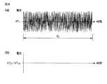
応答特性Rは、テスト駆動信号VTに対するノズル内の流速振動UTから求める。具体的には、テスト駆動信号VT1〜VT10を各々の電極12a〜12jに印加する。駆動信号VT1は、図8に示すように低電圧の周期Tcのノイズ波形であり、駆動信号VT2〜VT10は0Vとする。Tcは、インク吐出動作の時間より十分長くすることが望ましい。さらに、電極12kに対しては電極12aと同じ駆動信号VT1を印加することで、多数の圧力室に対して10チャンネルおきの駆動パターンを適用する。そのような駆動パターンでヘッドを駆動するときのノズル10a〜10j内のメニスカスの流速を各々UT1〜UT10としたとき、図9に示すような周期Tcの流速振動が発生する。この流速振動は、市販のレーザードップラー振動計、例えば(株)小野測器のLV−1710を用い、インクジェットヘッドのノズル内のメニスカスに測定用レーザビームを照射することによって観測することができる。
続いて、下記の(1)式と(2)式を用いて、テスト駆動信号VTと、流速振動UTをフーリエ変換し、それぞれ電圧スペクトルFVTと流速スペクトルFUTに変換する。
The response characteristic R is obtained from the flow velocity vibration UT in the nozzle with respect to the test drive signal VT. Specifically, test drive signals VT1 to VT10 are applied to the
Subsequently, using the following equations (1) and (2), the test drive signal VT and the flow velocity vibration UT are Fourier transformed to be converted into a voltage spectrum FVT and a flow velocity spectrum FUT, respectively.
ここで、mは、レーザードップラー振動計で観測された時系列流速データのデータ数である。レーザードップラー振動計で観測された流速データのサンプリング時間をdtとすれば、mはTc/dtの値となる。添字のiは、チャンネル番号を示す1から10までの整数であり、この番号は電極12a〜12j、又は、ノズル10a〜10jに対応している。また、添字のjは、時系列データにおいて先頭からj番目のデータを示す1〜mまでの整数である。j番目のデータは、時刻j×dtのデータを示している。添字のkは、周波数系列データにおいて先頭からk番目のデータを示す1〜mまでの整数である。k番目のデータは、周波数(k−1)/Tcのデータを示している。Iは虚数単位である。ここで述べた添字の記法は以下の説明においても用いることとする。VTi、UTiは時間間隔dtで長さmの時系列データであり、また、FVTi、FUTiは、周波数間隔1/(m dt)おきの周波数系列データである。Here, m is the number of time-series flow velocity data observed with a laser Doppler vibrometer. If the sampling time of flow velocity data observed with a laser Doppler vibrometer is dt, m is a value of Tc / dt. The subscript i is an integer from 1 to 10 indicating the channel number, and this number corresponds to the
次にFVTとFUTから、下記(3)式により応答特性Rを求める。
Ri,k=FUTi,k/FVT1,k …(3)
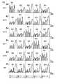
Ri,kは、駆動信号VT1に対するノズル内のメニスカス流速Uiの周波数(k−1)/Tcにおける振幅と位相の変化を複素数の形で示している。Riを各チャンネルの応答特性とするとき、R1〜R10の絶対値を図10に示し、位相角を図11に示す。図10のfmaxは、ノズル10内のメニスカスが、駆動信号に対して低周波領域から連続して応答可能な周波数領域の上限の周波数である。Next, the response characteristic R is obtained from the FVT and FUT by the following equation (3).
Ri, k = FUTi, k / FVT1, k (3)
Ri, k represents the change in amplitude and phase in the frequency (k−1) / Tc of the meniscus flow velocity Ui in the nozzle with respect to the drive signal VT1 in the form of a complex number. When the Ri and response characteristics of eachchannel, the absolute value of the
ここでは、テスト駆動信号VTとしてノイズ波形を求める場合について説明したが、テスト駆動信号として周波数可変の正弦波や余弦波を用い、各周波数におけるメニスカス流速振動の振幅と位相を測定することによって応答特性Rを求めることも可能である。 Here, the case where the noise waveform is obtained as the test drive signal VT has been described. However, the response characteristics are obtained by measuring the amplitude and phase of the meniscus flow velocity vibration at each frequency using a variable frequency sine wave or cosine wave as the test drive signal. R can also be obtained.
次に、上記方法で求めた応答特性Rを用い、仮想メニスカス振動から駆動信号を決定する方法について述べる。
図12は仮想メニスカス振動の変位Xを示す図である。例えば、圧力室9cから第1〜第3ドロップを吐出させ、圧力室9hからはインクを吐出させない場合、ノズル10a〜10jの仮想メニスカス変位はそれぞれX1〜X10となる。仮想メニスカス変位のプラス側の山のピークが各ドロップのインクの吐出体積に相当する。Next, a method for determining a drive signal from virtual meniscus vibration using the response characteristic R obtained by the above method will be described.
FIG. 12 is a diagram showing the displacement X of the virtual meniscus vibration. For example, by discharging the first to third drop from the
次に、仮想メニスカス変位Xに対応する仮想メニスカス流速を求める。仮想メニスカス変位Xは、下記(4)式の演算を行う都合上、始点と終点が実質的に連続で、始点から終点まで微分した結果が連続であり、かつ、微分した結果の始点と終点も実質的に連続である。仮想メニスカス流速Uは、下記(4)式により求められる。 Next, a virtual meniscus flow velocity corresponding to the virtual meniscus displacement X is obtained. The virtual meniscus displacement X is substantially continuous from the start point to the end point for the convenience of the calculation of the following equation (4), the result of differentiation from the start point to the end point is continuous, and the start point and end point of the differentiated result are also Substantially continuous. The virtual meniscus flow velocity U is obtained by the following equation (4).
Ui=d/dt・Xi …(4)
図13に、上記(4)式により求めた仮想メニスカス流速U1〜U10を示す。
仮想メニスカス流速Uは始点から終点まで実質的に連続な時系列データで、また始点と終点も実質的に連続である。仮想メニスカス流速を仮想メニスカス変位から演算する代わりに最初から仮想メニスカス流速を定義しても良い。Ui = d / dt · Xi (4)
FIG. 13 shows virtual meniscus flow velocities U1 to U10 obtained by the above equation (4).
The virtual meniscus flow velocity U is time series data that is substantially continuous from the start point to the end point, and the start point and the end point are also substantially continuous. Instead of calculating the virtual meniscus flow velocity from the virtual meniscus displacement, the virtual meniscus flow velocity may be defined from the beginning.
次に、下記(5)を用いて仮想メニスカス流速Uのフーリエ変換を行い、仮想メニスカス流速Uの流速スペクトルFUを得る。
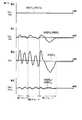
ここで、Uiは時間間隔dtで長さmの時系列データであり、UTi,jは、UTiの先頭からj番目のデータである。また、流速スペクトルFUi,kは、仮想メニスカス流速Ui周波数(k−1)/Tcにおける流速振幅と位相の複素数の形で表している。このようにして得られた流速スペクトルFUのうち、FU3の絶対値を図14に示す。この流速スペクトルFUの周波数の大部分は、図14に示すように前述した周波数fmaxより低い周波数に含まれることが望ましい。Here, Ui is time-series data having a time interval dt and a length m, and UTi, j is j-th data from the top of UTi . The flow velocity spectrum FUi, k is represented in the form of a complex number of the flow velocity amplitude and phase at the virtual meniscus flow velocity Ui frequency (k−1) / Tc. Of the flow velocity spectrum FU thus obtained, the absolute value of FU3 is shown in FIG. As shown in FIG. 14, most of the frequency of the flow velocity spectrum FU is preferably included in a frequency lower than the above-described frequency fmax.
次に、インクジェットヘッドの応答特性Rと仮想メニスカス振動の流速スペクトルFUとから、駆動信号の電圧スペクトルFVAを求める。応答特性行列[R]kを下記(6)式、電圧ベクトル{FVA}kを下記(7)式、仮想メニスカス振動の流速ベクトル{FU}kを下記(8)式としたとき、下記(9)式により周波数(k−1)/Tcにおける電圧ベクトルFVAkが求められる。
{FVA}k=[R]k−1・{FUA}k …(9)
(7)式および(9)式で得られた電圧スペクトルFVAi,kは、仮想メニスカス流速Uiを発生させる駆動信号VAiの、周波数(k−1)/Tcにおける電圧振幅と位相を複素数の形で表している。また、(6)式で得られる[R]kのa行b列目の要素は、b番目のチャンネルの周波数(k−1)/Tcの電圧振動に対するa番目のノズル内のメニスカス流速振動の振幅と位相の変化を複素数の形で表している。[R]k−1は[R]kの逆行列である。逆行列の演算は、WOLFRAM RESEARCH社のMATHEMATICAなどの数式解析ソフトウエアにより行うことができる。{FVA}k = [R]k−1 · {FUA}k (9)
The voltage spectrum FVAi, k obtained by the equations (7) and (9) is a complex number representing the voltage amplitude and phase at the frequency (k−1) / Tc of the drive signal VAi for generating the virtual meniscus flow velocity Ui. It is expressed in the form of In addition, the element in the a row and the b column of [R]k obtained by the equation (6) is the meniscus flow velocity vibration in the a-th nozzle with respect to the voltage vibration of the frequency (k-1) / Tc of the b-th channel. Changes in amplitude and phase are represented in complex form. [R]k−1 is an inverse matrix of [R]k . The inverse matrix can be calculated by mathematical analysis software such as MATHEMATICA of WOLFRAM RESEARCH.
次に、駆動信号VAを求める。駆動信号VAは、電圧スペクトルFVAを、下記(10)式により逆フーリエ変換することにより求めることができる。
ここで、Re[z]は、複素数z=a+bIの実数部aを得る関数である。VAi,jは、仮想メニスカス流速Uを発生させる駆動信号VAの、i番目のチャンネルの時刻j×dtにおける電圧値である。Here, Re [z] is a function for obtaining the real part a of the complex number z = a + bI. VAi, j is a voltage value at the time j × dt of the i-th channel of the drive signal VA for generating the virtual meniscus flow velocity U.
このように得られた駆動信号VAi、すなわちVA1〜VA10は、それぞれ電極12a〜12jに印加された場合、ノズル10a〜10j内のメニスカスに仮想メニスカス変位X1〜X10を生じさせる駆動信号になる。When the drive signals VAi obtained as described above, that is, VA1 to VA10 are applied to the
また、m′は、
m′≦fmax・Tc
となる最も大きい整数である。このように逆フーリエ変換の周波数の上限をfmaxとすることにより、駆動信号VAの周波数成分の上限値がfmaxに定められる。M ′ is
m ′ ≦ fmax · Tc
Is the largest integer. Thus, by setting the upper limit of the frequency of the inverse Fourier transform to fmax, the upper limit value of the frequency component of the drive signal VA is set to fmax.
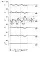
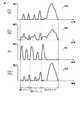
このように、駆動信号の波形を仮想メニスカス振動からフーリエ変換を用いて逆算する場合、演算を行う周波数の範囲をインクジェットヘッドが応答する周波数の範囲である0〜fmaxに制限することにより、計算結果が発散することを防止できる。計算の結果得られた波形の駆動信号が十分な精度で仮想メニスカス振動を再現するためには、fmaxが流速スペクトルFUの周波数成分の大部分を含んでいることが望ましい。fmaxは、圧力室の長さLなどのインクジェットヘッドの寸法によって変化する。したがって、fmaxが流速スペクトルFUの周波数成分の大部分を含むよう、インクジェットヘッドの寸法を調整することが望ましい。以上のようにして得られた駆動信号VA(VA1〜VA10)を図15に示す。As described above, when the waveform of the drive signal is back-calculated from the virtual meniscus vibration using Fourier transform, the calculation result is obtained by limiting the frequency range for the calculation to 0 to fmax that is the frequency range to which the inkjet head responds. Can be prevented from spreading. In order for the drive signal having the waveform obtained as a result of the calculation to reproduce the virtual meniscus vibration with sufficient accuracy, it is desirable that fmax includes most of the frequency components of the flow velocity spectrum FU. fmax varies depending on the dimensions of the inkjet head, such as the length L of the pressure chamber. Therefore, it is desirable to adjust the dimensions of the inkjet head so that fmax includes most of the frequency components of the flow velocity spectrum FU. FIG. 15 shows drive signals VA (VA1 to VA10 ) obtained as described above.
以上のようにして得られた駆動信号VAは、そのままインクジェットヘッドの駆動信号として用いることが可能であるが、駆動信号VAから図15に点線で示すような基準電圧波形VREF(VREF1〜VREF10)との差を計算して、図16に示す駆動信号VB(VB1〜VB10)を得ることにより、駆動信号の長さを短縮できる。このことにより、インクジェットヘッドの駆動周期を短縮でき、印刷速度を向上させることができる。The drive signal VA obtained as described above can be used as it is as a drive signal for the inkjet head, but the reference voltage waveform VREF (VREF1 to VREF10 as shown by the dotted line in FIG. 15 from the drive signal VA. ) To obtain the drive signals VB (VB1 to VB10 ) shown in FIG. 16, the drive signal length can be shortened. As a result, the drive cycle of the inkjet head can be shortened, and the printing speed can be improved.
以上のようにして得られた駆動信号VBは、そのままインクジェットヘッドの駆動信号として用いることが可能であるが、さらに下記(11)式で示される駆動信号VDを得ることにより、駆動信号の電圧振幅を小さくできる。このことにより、駆動回路のコストを低減でき、安価なインクジェット記録装置を提供できる。図17に、駆動信号VD1〜VD10を示す。The drive signal VB obtained as described above can be used as it is as a drive signal for the ink jet head. However, by obtaining the drive signal VD represented by the following equation (11), the voltage amplitude of the drive signal is obtained. Can be reduced. As a result, the cost of the drive circuit can be reduced, and an inexpensive ink jet recording apparatus can be provided. FIG. 17 shows drive signals VD1 to VD10 .
VDi,j=VBi,j−MIN[VB1,j,VB2,j,…VB10,j] …(11)
ここで、MIN[VB1,j,VB2,j,…]は、[]内の値のうち最小の値を示す関数である。この計算で求めた駆動信号VD3は駆動信号W1になり、駆動信号VD2またはVD4は駆動信号W2になり、駆動信号VD1またはVD5は駆動信号W3になり、駆動信号VD6〜VD10のいずれかは駆動信号W4になる。VDi, j = VBi, j −MIN [VB1, j , VB2, j ,... VB10, j ] (11)
Here, MIN [VB1, j , VB2, j ,...] Is a function indicating the minimum value among the values in []. The calculation by the drive signal VD3 obtained becomes drive signal W1, drive signal VD2 or VD4 becomes drive signal W2, drive signal VD1 or VD5 becomes drive signal W3, drive
以上述べた駆動信号の作成方法をインクジェット記録装置の製造に応用するには、以下の手順で行う。まず、ノイズ波形あるいは正弦波などの適当なテスト駆動信号を用い、製造されたインクジェットヘッドの電圧信号に対するメニスカスの応答特性Rを測定する。次に、応答特性Rと、あらかじめ定められた仮想メニスカス振動をもとに、(4)式〜(10)式により駆動信号の波形を演算により作成する。次に、必要に応じて(11)式などにより駆動信号の波形を変形する。最後に、得られた駆動信号の波形をインクジェット記録装置の駆動波形メモリ21に記憶させる。 To apply the drive signal generation method described above to the manufacture of an ink jet recording apparatus, the following procedure is used. First, using a suitable test drive signal such as a noise waveform or a sine wave, the response characteristic R of the meniscus to the voltage signal of the manufactured inkjet head is measured. Next, based on the response characteristic R and a predetermined virtual meniscus vibration, the waveform of the drive signal is created by calculation using equations (4) to (10). Next, if necessary, the waveform of the drive signal is deformed by the equation (11) or the like. Finally, the waveform of the obtained drive signal is stored in the
続いて、仮想メニスカス振動について詳細に述べる。図12に示す変位X1〜X10は、圧力室9cから第1〜第3ドロップを吐出させ、圧力室9hからはインクを吐出させない場合の、各ノズル10a〜10jにおける仮想メニスカス振動の変位を示している。また、図13のU1〜U10は、各ノズル10a〜10jにおける仮想メニスカス流速を示している。Next, the virtual meniscus vibration will be described in detail. Displacements X1 to X10 shown in FIG. 12 are displacements of virtual meniscus vibrations in the nozzles 10a to 10j when the first to third drops are ejected from the
この実施の形態では、インクを吐出させるノズル10cの仮想メニスカス振動の変位X3において、第1ドロップ、第2ドロップ、第3ドロップの吐出時の吐出時間をそれぞれst1、st2、st3とし、インク吐出時の仮想メニスカス変位の動きをa1、a2、a3とするとき、
a1/st1≒a2/st2≒a3/st3
としている。このように仮想メニスカス振動を定めることにより、異なる体積のインクドロップを略一定の速度で吐出できる。In this embodiment, the displacementX 3 of hypothetical meniscus vibration in nozzle 10c for ejecting ink, first drop, second drop, a third drop ejection time during discharge of thest1,
a1 / st1 ≒ a2 / st2 ≒ a3 / st3
It is said. By defining the virtual meniscus vibration in this way, ink drops having different volumes can be ejected at a substantially constant speed.
また、ノズル10cに隣接するノズル10b、10dと、さらにノズル10b、10dに隣接するノズル10a、10eの仮想メニスカス振動X1、X2、X4、X5の変位は、ノズル10cの仮想メニスカス振動X3の−1/4にしている。このように仮想メニスカス振動を定めて、ノズル10cからのインク吐出動作に伴うノズル10b、10dのメニスカス振動をノズル10a、10eに分散させて、ノズル10b、10dに発生するメニスカス振動の振幅を低減させることにより、ノズル10b、10dのメニスカスが盛り上り、ノズル10bや10dから吐出するインク滴の速度や体積がばらつくのを低減できる。Further, the displacement of the virtual meniscus vibrations X1 , X2 , X4 , and X5 of the nozzles 10 b and 10 d adjacent to the nozzle 10 c and the nozzles 10 a and 10 e adjacent to the nozzles 10 b and 10 d are the virtual meniscus vibrations of the nozzle 10 c. X3 is -1/4. In this way, the virtual meniscus vibration is determined, and the meniscus vibration of the nozzles 10b and 10d accompanying the ink ejection operation from the nozzle 10c is dispersed to the nozzles 10a and 10e, thereby reducing the amplitude of the meniscus vibration generated in the nozzles 10b and 10d. As a result, the meniscus of the nozzles 10b and 10d swells, and variations in the speed and volume of the ink droplets ejected from the nozzles 10b and 10d can be reduced.
さらに、インクが吐出しないノズル10hと、ノズル10hに隣接するノズル10g、10iと、ノズル10g,10iに隣接するノズル10f,10jの仮想メニスカス流速U6〜U10の振幅を0にしている。これにより、ノズル10eに流速振動が発生しても、ノズル10fには流速振動が発生しない状態を仮想メニスカス振動により定義している。これは、圧力室9eに圧力振動が発生しても、圧力室9fには圧力振動が発生しない状態を仮想メニスカス振動により定義していると言える。すなわち、圧力室9eと圧力室9fの間のクロストークが0になることを仮想メニスカス振動により定義していることになる。Further, the amplitudes of the virtual meniscus flow rates U6 to U10 of the nozzle 10h that does not eject ink, the nozzles 10g and 10i adjacent to the nozzle 10h, and the nozzles 10f and 10j adjacent to the nozzles 10g and 10i are set to zero. Thereby, even if flow velocity vibration occurs in the nozzle 10e, the state where no flow velocity vibration occurs in the nozzle 10f is defined by virtual meniscus vibration. It can be said that a state in which no pressure vibration occurs in the
このように、メニスカスを振動させるノズル10a〜10eと、メニスカスを振動させないノズル10f〜10jの仮想メニスカス振動を定めて、この仮想メニスカス振動とインクジェットヘッドの応答特性とから駆動信号を逆算すると、メニスカスを振動させないノズル10f〜10jに対応するチャンネルの駆動信号として、図17にW4で示される駆動信号が得られる。この駆動信号W4は、ノズル10cからのインク吐出に伴う圧力室9eの圧力変動がアクチュエータ14fの変形を介して圧力室9fに伝達するのを遮断していることから、アクチュエータ14fの変形を実質的に0にする駆動信号ということになる。 As described above, when the virtual meniscus vibrations of the nozzles 10a to 10e that vibrate the meniscus and the nozzles 10f to 10j that do not vibrate the meniscus are determined, and the drive signal is calculated back from the virtual meniscus vibration and the response characteristics of the inkjet head, the meniscus is calculated. As a drive signal for the channel corresponding to the nozzles 10f to 10j that are not vibrated, a drive signal indicated by W4 in FIG. 17 is obtained. The drive signal W4 substantially blocks the deformation of the
図18はインクジェットヘッドに対して上述した制御が行われるインクジェット記録装置の要部外観を示す斜視図である。このインクジェット記録装置は、例えば、4個のインクジェットヘッド271,272,273,274を、基板28の両面に、交互にかつ位置も交互となるようにずらして配置して1つのラインヘッド29を構成している。 FIG. 18 is a perspective view showing an external appearance of a main part of an ink jet recording apparatus in which the above-described control is performed on the ink jet head. In this ink jet recording apparatus, for example, four ink jet heads 271, 272, 273, and 274 are arranged on both surfaces of the
前記ラインヘッド29は媒体搬送ベルト30から所定の隙間だけ離れた位置に設置されている。前記媒体搬送ベルト30は搬送ローラ31によって矢印の方向に駆動するもので、用紙などの記録媒体32を上面に密着した状態で搬送する。記録媒体32がラインヘッド29の下を通過するとき、各インクジェットヘッド271〜274から下向きにインク滴を吐出し、このインク滴を記録媒体32に付着させて印刷を行う。なお、記録媒体32を媒体搬送ベルト30に密着させる方法としては、静電気や空気流により吸着させる方法や、記録用紙の端を部材で押さえる方法など、周知の方法を用いることができる。 The
ラインヘッド29の各インクジェットヘッド271〜274は圧力室のノズルから吐出するインク滴のタイミングをインクジェットヘッド間で調整することで、各インクジェットヘッド271〜274により記録媒体32に対して同一ラインを印刷できるようになっている。これにより、このインクジェット記録装置に使用する各インクジェットヘッド271〜274は、残留振動を低減し吐出速度の変動を極力抑えることができる。 The inkjet heads 271 to 274 of the
なお、この実施の形態では、ノズル10f〜10jのメニスカス振動の振幅を0としたが、インクが吐出しない程度のメニスカス振動であれば、ノズル10f〜10jに適度のメニスカス振動を与えてやることも可能である。その場合は、仮想メニスカス振動X6〜X10に、小さな振幅を有するメニスカス振動を定義し、上記の方法を用いて駆動信号の波形を逆算すればよい。In this embodiment, the amplitude of the meniscus vibration of the nozzles 10f to 10j is set to 0. However, if the meniscus vibration is such that ink is not ejected, an appropriate meniscus vibration may be given to the nozzles 10f to 10j. Is possible. In that case, the hypothetical meniscus vibration X6 to X10, to define the meniscus vibration with a small amplitude may be calculated back waveform of the driving signal using the method described above.
なお、この実施の形態では駆動回路として、インクを吐出させる圧力室9に印加する駆動信号ACT1〜ACT5の波形情報及びインクを吐出させない圧力室9に印加する駆動信号INAの波形情報を記憶した駆動波形メモリ21を設け、この駆動波形メモリ21から駆動信号を読み出し、それを駆動信号選択手段24にて選択するようにしたが必ずしもこれに限定するものではない。 In this embodiment, as a drive circuit, a drive that stores waveform information of the drive signals ACT1 to ACT5 applied to the
例えば、図19に示すように、仮想メニスカス振動情報を記憶した仮想メニスカス振動メモリ33と、応答特性R情報を記憶した応答特性メモリ34と、演算手段35を設け、演算手段35にて、仮想メニスカス振動メモリ33の仮想メニスカス振動の変位から仮想メニスカス流速Uを求め、この仮想メニスカス流速Uから流速スペクトルFUを求め、この流速スペクトルFUと応答特性メモリ34に記憶した応答特性Rとから、駆動信号の電圧スペクトルFVAを求め、さらに(10)式および(11)式の演算を行って駆動信号をW1、W2、W3、W4を求めて駆動信号ACT1〜ACT5、INAを得るようにし、この駆動信号ACT1〜ACT5、INAを駆動信号選択手段24にて選択するようにしてもよい。 For example, as shown in FIG. 19, a virtual
この場合、演算手段35でfmax以上の電圧波形VAの周波数成分をカットするか、あらかじめ仮想メニスカス振動メモリ33に記憶される仮想メニスカス振動あるいは応答特性メモリ34に記憶される応答特性のfmax以上の周波数成分をカットしておくことが演算を簡単にするために望ましい。 In this case, the frequency component of the voltage waveform VA greater than or equal to fmax is cut by the computing means 35, or the virtual meniscus vibration stored in the virtual
また、前述した実施の形態は、インクを吐出可能な時分割タイミングにあるがインクを吐出させない圧力室を中心とした隣接する5個の圧力室、すなわち、圧力室9cから第1ドロップを吐出させ、圧力室9hからは第1ドロップを吐出させない場合において、圧力室9f〜9jの電極12f〜12jに同じ駆動信号W4aを同時に供給させるようにしたが必ずしもこれに限定するものではなく、少なくとも最も外側の圧力室である圧力室9fの電極12fに駆動信号W4aを供給すればよい。このようにしてもアクチュエータ14fには、駆動信号W3aとW4aの電位差により、圧力室9eに発生する圧力によりアクチュエータ14fが変形しようとするに抗する力が発生し、アクチュエータ14fが実質的に変形しなくなる。 In the above-described embodiment, the first drop is ejected from the five adjacent pressure chambers, that is, the
また、前述した実施の形態は、5分割駆動の場合について述べたがこれに限定するものではなく、3分割駆動でも上述の手順を適用することによって容易に実施できる。そして、3分割駆動においてもクロストークを実質的に0にすることができることは明らかである。また、7分割以上の奇数の時分割数においても同様である。 In the above-described embodiment, the case of the five-division drive is described. However, the present invention is not limited to this, and the three-division drive can be easily implemented by applying the above procedure. It is clear that the crosstalk can be substantially zero even in the three-division drive. The same applies to an odd number of time divisions of 7 or more.
9,9a〜9k…圧力室、10…ノズル、12,12a〜12k…電極、14a〜14k…アクチュエータ、21…駆動波形メモリ、24…駆動信号選択手段、27…インクジェットヘッド。 DESCRIPTION OF
Claims (5)
Translated fromJapanese前記圧力室を奇数の時分割数N(但し、N≧3)で時分割駆動する駆動信号を発生してそれぞれ対応する圧力室の電極に供給する駆動信号発生手段を備え、
前記駆動信号発生手段は、インクを吐出させる圧力室を中心とした(N+1)個の隣接するアクチュエータのうち最も外側のアクチュエータを挟む2つの電極間に電位差を与えることにより該最も外側のアクチュエータのインク圧力による変形を阻止する駆動信号を、インクを吐出可能な時分割タイミングにあるがインクを吐出させない圧力室を中心とした隣接するN個の圧力室のうち、少なくとも最も外側の圧力室の電極に供給することを特徴とするインクジェット記録装置。A plurality of nozzles that eject ink to perform image recording on a recording medium, a plurality of pressure chambers that communicate with the nozzles, an ink supply unit that supplies ink to the pressure chambers, and the pressure chambers A plurality of correspondingly arranged electrodes, a partition wall that separates the pressure chambers from each other, and an electrode corresponding to a pressure chamber for ejecting ink and an electrode corresponding to two pressure chambers adjacent to the pressure chamber an ink jet headfor discharging ink by varying the volume of the pressure chamber in accordance with the chromaticand the drive signaland an actuatorwhich deforms in response to a drive signal supplied to,
Drive signal generating means for generating a drive signal for time-sharing driving the pressure chambers with an odd number of time division numbers N (where N ≧ 3) and supplying the drive signals to the corresponding pressure chamber electrodes,
The drive signal generating means provides apotential difference between two electrodes sandwiching the outermost actuator among (N + 1) adjacent actuators centering on a pressure chamber for ejecting ink, whereby ink of theoutermost actuator A drive signal for preventing deformation due to pressure is applied to at least the electrode of the outermost pressure chamber among N adjacent pressure chambers centering on a pressure chamber that is in a time-sharing timing at which ink can be ejected but does not eject ink. An ink jet recording apparatus comprising: an ink jet recording apparatus;
Priority Applications (4)
| Application Number | Priority Date | Filing Date | Title |
|---|---|---|---|
| JP2005039397AJP4069123B2 (en) | 2005-02-16 | 2005-02-16 | Inkjet recording device |
| EP06002942AEP1693202A3 (en) | 2005-02-16 | 2006-02-14 | Ink jet recording apparatus |
| US11/353,980US7669987B2 (en) | 2005-02-16 | 2006-02-15 | Ink jet recording apparatus |
| CN200610009019.8ACN1820950B (en) | 2005-02-16 | 2006-02-16 | Ink jet recording apparatus |
Applications Claiming Priority (1)
| Application Number | Priority Date | Filing Date | Title |
|---|---|---|---|
| JP2005039397AJP4069123B2 (en) | 2005-02-16 | 2005-02-16 | Inkjet recording device |
Publications (2)
| Publication Number | Publication Date |
|---|---|
| JP2006224387A JP2006224387A (en) | 2006-08-31 |
| JP4069123B2true JP4069123B2 (en) | 2008-04-02 |
Family
ID=36337098
Family Applications (1)
| Application Number | Title | Priority Date | Filing Date |
|---|---|---|---|
| JP2005039397AExpired - Fee RelatedJP4069123B2 (en) | 2005-02-16 | 2005-02-16 | Inkjet recording device |
Country Status (4)
| Country | Link |
|---|---|
| US (1) | US7669987B2 (en) |
| EP (1) | EP1693202A3 (en) |
| JP (1) | JP4069123B2 (en) |
| CN (1) | CN1820950B (en) |
Families Citing this family (9)
| Publication number | Priority date | Publication date | Assignee | Title |
|---|---|---|---|---|
| JP2006231685A (en)* | 2005-02-24 | 2006-09-07 | Toshiba Tec Corp | Inkjet recording device |
| GB0820714D0 (en)* | 2008-11-12 | 2008-12-17 | Xaar Technology Ltd | Method and apparatus for droplet deposition |
| GB0820718D0 (en) | 2008-11-12 | 2008-12-17 | Xaar Technology Ltd | Method and apparatus for droplet deposition |
| JP4866457B2 (en)* | 2009-09-15 | 2012-02-01 | 東芝テック株式会社 | Inkjet recording apparatus and crosstalk reduction method |
| CN102114731B (en)* | 2009-12-31 | 2014-04-16 | 香港应用科技研究院有限公司 | Printhead for thermal inkjet printing and printing method thereof |
| JP2015085593A (en) | 2013-10-30 | 2015-05-07 | 株式会社東芝 | Inkjet head |
| JP2016010937A (en) | 2014-06-30 | 2016-01-21 | 株式会社リコー | Image forming apparatus and head drive control method |
| JP6613655B2 (en)* | 2015-06-26 | 2019-12-04 | 株式会社リコー | Droplet ejection apparatus, droplet ejection method, and program |
| GB2563235B (en) | 2017-06-06 | 2021-05-26 | Xaar Technology Ltd | Method and apparatus for droplet deposition |
Family Cites Families (9)
| Publication number | Priority date | Publication date | Assignee | Title |
|---|---|---|---|---|
| JPH07132590A (en)* | 1993-11-09 | 1995-05-23 | Brother Ind Ltd | Driving method of ink jet device |
| JPH11207951A (en)* | 1998-01-22 | 1999-08-03 | Brother Ind Ltd | INK JET PRINTER AND INK DISCHARGE CONTROL METHOD IN INK JET PRINTER |
| JP4277346B2 (en) | 1999-03-08 | 2009-06-10 | コニカミノルタホールディングス株式会社 | Ink jet head driving method |
| DE19911399C2 (en)* | 1999-03-15 | 2001-03-01 | Joachim Heinzl | Method for controlling a piezo print head and piezo print head controlled according to this method |
| JP2002086712A (en) | 2000-09-08 | 2002-03-26 | Sharp Corp | Driving method of inkjet head |
| US7073893B2 (en)* | 2002-12-03 | 2006-07-11 | Konica Minolta Holdings Inc. | Inkjet recording head |
| DE60317760T2 (en) | 2002-12-05 | 2008-10-30 | Toshiba Tec K.K. | Inkjet head and inkjet printer |
| US7117138B2 (en)* | 2003-03-14 | 2006-10-03 | Seiko Epson Corporation | Coupled quadrilateral grid level set scheme for piezoelectric ink-jet simulation |
| JP2006231685A (en)* | 2005-02-24 | 2006-09-07 | Toshiba Tec Corp | Inkjet recording device |
- 2005
- 2005-02-16JPJP2005039397Apatent/JP4069123B2/ennot_activeExpired - Fee Related
- 2006
- 2006-02-14EPEP06002942Apatent/EP1693202A3/ennot_activeWithdrawn
- 2006-02-15USUS11/353,980patent/US7669987B2/ennot_activeExpired - Fee Related
- 2006-02-16CNCN200610009019.8Apatent/CN1820950B/ennot_activeExpired - Fee Related
Also Published As
| Publication number | Publication date |
|---|---|
| US7669987B2 (en) | 2010-03-02 |
| US20060187273A1 (en) | 2006-08-24 |
| EP1693202A2 (en) | 2006-08-23 |
| CN1820950A (en) | 2006-08-23 |
| JP2006224387A (en) | 2006-08-31 |
| CN1820950B (en) | 2010-05-12 |
| EP1693202A3 (en) | 2007-12-26 |
Similar Documents
| Publication | Publication Date | Title |
|---|---|---|
| US7367658B2 (en) | Ink jet recording apparatus | |
| EP1378358B1 (en) | Apparatus for driving ink jet head | |
| US7669987B2 (en) | Ink jet recording apparatus | |
| US10239313B2 (en) | Inkjet head drive apparatus | |
| US7651203B2 (en) | Inkjet recording device, ejecting device provided therein, and method of calibrating ejection characteristic for droplet | |
| US7625053B2 (en) | Ink jet recording apparatus | |
| US8061819B2 (en) | Liquid ejecting method, liquid ejecting head, and liquid ejecting apparatus | |
| WO2005120840A1 (en) | Ink jet recording device and ink jet recording method | |
| JP4700375B2 (en) | Ink jet head driving method and ink jet recording apparatus | |
| JP5290343B2 (en) | Waveform generation method of inkjet head drive signal and inkjet recording apparatus | |
| JP4763331B2 (en) | Waveform generation method of inkjet head drive signal and inkjet recording apparatus | |
| JP4815249B2 (en) | Inkjet recording device | |
| JP4672423B2 (en) | Inkjet recording device | |
| JP5432627B2 (en) | Inkjet recording device | |
| JP2007118294A (en) | Ink jet head driving apparatus and driving method | |
| JPH0691204A (en) | Piezoelectric liquid droplet ejection device | |
| JP2011067999A (en) | Method of ejecting liquid and liquid ejection device | |
| JP2011084028A (en) | Liquid ejection method and liquid ejection device | |
| JP4039261B2 (en) | Natural vibration period measuring device | |
| JP2012218184A (en) | Drive signal setting method, driving method of liquid ejection head, and liquid ejection head | |
| GB2445117A (en) | Droplet ejecting device and method of calibrating ejection characteristics | |
| JP2006001075A (en) | Inkjet head driving method, driving apparatus, and inkjet recording apparatus | |
| JP2007111965A (en) | Ink jet head driving method and ink jet recording apparatus |
Legal Events
| Date | Code | Title | Description |
|---|---|---|---|
| A977 | Report on retrieval | Free format text:JAPANESE INTERMEDIATE CODE: A971007 Effective date:20070719 | |
| A131 | Notification of reasons for refusal | Free format text:JAPANESE INTERMEDIATE CODE: A131 Effective date:20070731 | |
| A521 | Request for written amendment filed | Free format text:JAPANESE INTERMEDIATE CODE: A523 Effective date:20070928 | |
| TRDD | Decision of grant or rejection written | ||
| A01 | Written decision to grant a patent or to grant a registration (utility model) | Free format text:JAPANESE INTERMEDIATE CODE: A01 Effective date:20080108 | |
| A61 | First payment of annual fees (during grant procedure) | Free format text:JAPANESE INTERMEDIATE CODE: A61 Effective date:20080111 | |
| FPAY | Renewal fee payment (event date is renewal date of database) | Free format text:PAYMENT UNTIL: 20110118 Year of fee payment:3 | |
| R150 | Certificate of patent or registration of utility model | Ref document number:4069123 Country of ref document:JP Free format text:JAPANESE INTERMEDIATE CODE: R150 Free format text:JAPANESE INTERMEDIATE CODE: R150 | |
| FPAY | Renewal fee payment (event date is renewal date of database) | Free format text:PAYMENT UNTIL: 20110118 Year of fee payment:3 | |
| FPAY | Renewal fee payment (event date is renewal date of database) | Free format text:PAYMENT UNTIL: 20120118 Year of fee payment:4 | |
| FPAY | Renewal fee payment (event date is renewal date of database) | Free format text:PAYMENT UNTIL: 20120118 Year of fee payment:4 | |
| FPAY | Renewal fee payment (event date is renewal date of database) | Free format text:PAYMENT UNTIL: 20130118 Year of fee payment:5 | |
| FPAY | Renewal fee payment (event date is renewal date of database) | Free format text:PAYMENT UNTIL: 20130118 Year of fee payment:5 | |
| FPAY | Renewal fee payment (event date is renewal date of database) | Free format text:PAYMENT UNTIL: 20140118 Year of fee payment:6 | |
| LAPS | Cancellation because of no payment of annual fees |