JP4063785B2 - Method of controlling lens ultrasonic suction system and lens ultrasonic suction device - Google Patents
Method of controlling lens ultrasonic suction system and lens ultrasonic suction deviceDownload PDFInfo
- Publication number
- JP4063785B2 JP4063785B2JP2004087335AJP2004087335AJP4063785B2JP 4063785 B2JP4063785 B2JP 4063785B2JP 2004087335 AJP2004087335 AJP 2004087335AJP 2004087335 AJP2004087335 AJP 2004087335AJP 4063785 B2JP4063785 B2JP 4063785B2
- Authority
- JP
- Japan
- Prior art keywords
- handpiece
- ultrasonic
- vacuum
- duty cycle
- suction
- Prior art date
- Legal status (The legal status is an assumption and is not a legal conclusion. Google has not performed a legal analysis and makes no representation as to the accuracy of the status listed.)
- Expired - Lifetime
Links
- 238000000034methodMethods0.000titleclaimsdescription38
- 239000012530fluidSubstances0.000claimsdescription93
- 238000004140cleaningMethods0.000claimsdescription60
- 210000000695crystalline lenAnatomy0.000claimsdescription43
- 238000002604ultrasonographyMethods0.000claimsdescription31
- 238000004891communicationMethods0.000claimsdescription6
- 230000008569processEffects0.000claimsdescription4
- 238000004590computer programMethods0.000claims1
- 230000002572peristaltic effectEffects0.000description11
- 238000001356surgical procedureMethods0.000description10
- 238000010586diagramMethods0.000description8
- 239000000463materialSubstances0.000description6
- 230000004044responseEffects0.000description6
- 230000003247decreasing effectEffects0.000description5
- 230000002262irrigationEffects0.000description5
- 238000003973irrigationMethods0.000description5
- 208000006440Open BiteDiseases0.000description4
- 208000002177CataractDiseases0.000description3
- 238000013459approachMethods0.000description3
- 230000008859changeEffects0.000description2
- 210000003128headAnatomy0.000description2
- 239000000126substanceSubstances0.000description2
- 230000007704transitionEffects0.000description2
- 206010027646MiosisDiseases0.000description1
- 230000000740bleeding effectEffects0.000description1
- 230000008878couplingEffects0.000description1
- 238000010168coupling processMethods0.000description1
- 238000005859coupling reactionMethods0.000description1
- 238000007599dischargingMethods0.000description1
- 238000004945emulsificationMethods0.000description1
- 238000000605extractionMethods0.000description1
- 238000001802infusionMethods0.000description1
- 238000003780insertionMethods0.000description1
- 230000037431insertionEffects0.000description1
- 239000007788liquidSubstances0.000description1
- 238000002406microsurgeryMethods0.000description1
- 238000012986modificationMethods0.000description1
- 230000004048modificationEffects0.000description1
- 238000011017operating methodMethods0.000description1
- 230000003287optical effectEffects0.000description1
- 238000005406washingMethods0.000description1
Images


Classifications
- A—HUMAN NECESSITIES
- A61—MEDICAL OR VETERINARY SCIENCE; HYGIENE
- A61F—FILTERS IMPLANTABLE INTO BLOOD VESSELS; PROSTHESES; DEVICES PROVIDING PATENCY TO, OR PREVENTING COLLAPSING OF, TUBULAR STRUCTURES OF THE BODY, e.g. STENTS; ORTHOPAEDIC, NURSING OR CONTRACEPTIVE DEVICES; FOMENTATION; TREATMENT OR PROTECTION OF EYES OR EARS; BANDAGES, DRESSINGS OR ABSORBENT PADS; FIRST-AID KITS
- A61F9/00—Methods or devices for treatment of the eyes; Devices for putting in contact-lenses; Devices to correct squinting; Apparatus to guide the blind; Protective devices for the eyes, carried on the body or in the hand
- A61F9/007—Methods or devices for eye surgery
- A61F9/00736—Instruments for removal of intra-ocular material or intra-ocular injection, e.g. cataract instruments
- A61F9/00745—Instruments for removal of intra-ocular material or intra-ocular injection, e.g. cataract instruments using mechanical vibrations, e.g. ultrasonic
- A—HUMAN NECESSITIES
- A61—MEDICAL OR VETERINARY SCIENCE; HYGIENE
- A61M—DEVICES FOR INTRODUCING MEDIA INTO, OR ONTO, THE BODY; DEVICES FOR TRANSDUCING BODY MEDIA OR FOR TAKING MEDIA FROM THE BODY; DEVICES FOR PRODUCING OR ENDING SLEEP OR STUPOR
- A61M1/00—Suction or pumping devices for medical purposes; Devices for carrying-off, for treatment of, or for carrying-over, body-liquids; Drainage systems
- A61M1/71—Suction drainage systems
- A61M1/77—Suction-irrigation systems
- A—HUMAN NECESSITIES
- A61—MEDICAL OR VETERINARY SCIENCE; HYGIENE
- A61B—DIAGNOSIS; SURGERY; IDENTIFICATION
- A61B17/00—Surgical instruments, devices or methods
- A61B2017/00017—Electrical control of surgical instruments
- A61B2017/00022—Sensing or detecting at the treatment site
- A—HUMAN NECESSITIES
- A61—MEDICAL OR VETERINARY SCIENCE; HYGIENE
- A61B—DIAGNOSIS; SURGERY; IDENTIFICATION
- A61B17/00—Surgical instruments, devices or methods
- A61B2017/00017—Electrical control of surgical instruments
- A61B2017/00137—Details of operation mode
- A61B2017/00141—Details of operation mode continuous, e.g. wave
- A61B2017/00146—Details of operation mode continuous, e.g. wave with multiple frequencies
- A—HUMAN NECESSITIES
- A61—MEDICAL OR VETERINARY SCIENCE; HYGIENE
- A61M—DEVICES FOR INTRODUCING MEDIA INTO, OR ONTO, THE BODY; DEVICES FOR TRANSDUCING BODY MEDIA OR FOR TAKING MEDIA FROM THE BODY; DEVICES FOR PRODUCING OR ENDING SLEEP OR STUPOR
- A61M2210/00—Anatomical parts of the body
- A61M2210/06—Head
- A61M2210/0612—Eyes
Landscapes
- Health & Medical Sciences (AREA)
- Heart & Thoracic Surgery (AREA)
- Life Sciences & Earth Sciences (AREA)
- Animal Behavior & Ethology (AREA)
- Engineering & Computer Science (AREA)
- Biomedical Technology (AREA)
- Ophthalmology & Optometry (AREA)
- Vascular Medicine (AREA)
- Veterinary Medicine (AREA)
- Public Health (AREA)
- General Health & Medical Sciences (AREA)
- Surgery (AREA)
- Nuclear Medicine, Radiotherapy & Molecular Imaging (AREA)
- Pulmonology (AREA)
- Anesthesiology (AREA)
- Hematology (AREA)
- Surgical Instruments (AREA)
- External Artificial Organs (AREA)
Description
Translated fromJapaneseこの発明は、水晶体超音波吸引装置並びに水晶体超音波吸引システムの制御方法、例えば、種々の外科手術との関連、より一般的には医療処置において、供給源から患者への流体の流れおよび患者からの流体の除去を制御するために用いられる水晶体超音波吸引システムの制御方法および水晶体超音波吸引装置に関する。 The present invention relates to a method for controlling a lens ultrasound suction device and a lens ultrasound suction system, such as fluid flow from a source to a patient and from a patient in the context of various surgical procedures, and more generally in medical procedures. The present invention relates to a method for controlling a lens ultrasonic suction system and a lens ultrasonic suction device used for controlling the removal of fluid.
患者へのおよび患者からの流体注入又は抽出系を通しての流体の流れは、電動式又はエア駆動のカッタおよび水晶体超音波吸引具等の手術具が共通に用いられる眼のマイクロサージェリィにおける如く、実行される手術にとってしばしば重大である。これらの器具は、手術部位に注入するための流体源と注入流体および手術部位からの屑を排出するための負圧源とを必要とする。 Fluid flow to and from the fluid infusion or extraction system to and from the patient, as in eye microsurgery where surgical tools such as motorized or air-driven cutters and phacoemulsifiers are commonly used, Often critical to the surgery performed. These instruments require a fluid source for injecting into the surgical site and a negative pressure source for discharging the infused fluid and debris from the surgical site.
医学的に認められた多数の手法が水晶体除去に利用されてきており、これらの中で、汎用されている手法は、水晶体超音波吸引、洗浄および吸引である。この方法は、典型的には出血を減少させるために焼灼される角膜切開および水晶体レンズを乳化するための超音波駆動の針を含む手持ちの外科器具の挿入を含む。この乳化と同時に、乳化された水晶体の洗浄のために流体が注入され、乳化された水晶体と注入された流体の吸引のために真空が与えられる。 Numerous medically recognized techniques have been used for lens removal, and among these, the techniques commonly used are lens ultrasonic aspiration, cleaning and aspiration. This method typically involves the insertion of a hand-held surgical instrument including a corneal incision that is cauterized to reduce bleeding and an ultrasonically driven needle to emulsify the lens. Simultaneously with this emulsification, a fluid is injected to clean the emulsified lens and a vacuum is applied to suck the emulsified lens and the injected fluid.
上で記述した水晶体超音波吸引手法は、眼科学の分野で周知であり、1960年代の後半およびチャールス・ケルマン博士の仕事に遡ぼる。水晶体超音波吸引法の詳しい議論は、リー・ティ・ノーマン(Lee T. Norman)、ダブリュ・アンドリュウ・マックスウエル(W. Andrew Maxwell)およびジェイムズ・エイ・デイブソン(James A. Davison)編集、ゴウア・メディカル出版(Gower Medical Publishing)による非特許文献1、ニューヨーク、NY、1992、ISBN 0−397−44693−4の第11章“水晶体超音波吸引の機構(The Mechanics of Phacoemulsification)”、第12章“水晶体超音波吸引手術(The Phacoemulsification Procedure)”、第13章“水晶体超音波吸引による白内障除去(Cataract removal by Phacoemulsification)”、および第14章“視力の外科的リハビリテーションの小瞳孔水晶体超音波吸引手法(Small pupil Phacoemulsification Techniques of The Surgical Rehabilitation of Vision)”に見い出される。非特許文献1のこれら第11章から第14章はその全体が本明細書において援用される。 The lens ultrasound aspiration technique described above is well known in the field of ophthalmology and dates back to the late 1960s and the work of Dr. Charles Kelman. For a detailed discussion of phacoemulsification, see Lee T. Norman, W. Andrew Maxwell, and James A. Davison, Gore Non-Patent Document 1, New York, NY, 1992, ISBN 0-397-44693-4, Chapter 11 “The Mechanics of Phacoemulsification” by Gower Medical Publishing,
現在入手できる水晶体超音波吸引システムは、マサチューセッツ、ノース・アンドーバアのオプティカル・マイクロ・システムズ・インコーポレイテッド(Optical Micro Systems,Inc.)により、“DIPLOMATE”、“DIPLOMATE MMP”、“OPSYS”および“OPSYS MMP”という商標のもとに、製造、販売されている。これらのシステムは、可変速ぜん動ポンプ、真空センサ、調節可能な超音波源および吸引割合、真空および超音波レベルについてオペレータが選択したプリセットを用いたプログラム可能なマイクロプロセッサを含む制御ユニットを有する。 Lens ultrasound aspiration systems currently available are "DIPLOMAT", "DIPLOMATE MMP", "OPSYS" and "OPSYS MMP" by Optical Micro Systems, Inc. of North Andover Manufactured and sold under the trademark "". These systems have a control unit including a variable speed peristaltic pump, a vacuum sensor, an adjustable ultrasound source and suction rate, a programmable microprocessor with operator selected presets for vacuum and ultrasound levels.
今日使用されている多くの外科器具および制御では、真空を線形制御するか、又は吸引流体の流れを線形制御する。この様式では、手術者が、真空度又は流れのいずれか一方、しかし両方ではない、を正確に与える或いは選択した速度に制御することが可能である。しかしながら、手術中に可変量(真空度、吸引割合、超音波レベル)の1つの正確な制御がいま1つの量にまして要求される時がしばしば存在する。真空度と流れとの関係を理解している経験を積んだユーザは、許容できる挙動を得るためにコンソールでプリセットされた可変量を適当に手動で修正する。しかし、この調整が見逃されると、高い真空度と速い流れの組合わせにより、手術部位において好ましくない流体的激変を惹起し、患者にダメージを与える。水晶体外科手術に用いられる手持ちの手術器具の制御は複雑であることは考慮されるべきである。水晶体超音波吸引装置は、典型的には、白内障レンズの超音波吸引を実行するために、電源、ぜん動ポンプ、電子および付属ハードウエアを含むキャビネットと接続された、中空の細い針管を含む多機能手持ち手術具即ちハンドピースとからなる。 Many surgical instruments and controls in use today have a linear control of the vacuum or a linear control of the suction fluid flow. In this manner, it is possible for the surgeon to accurately provide or control the selected rate, either vacuum level or flow, but not both. However, there are often times when one precise control of variable amounts (vacuum level, suction rate, ultrasound level) is required over another amount during surgery. Experienced users who understand the relationship between vacuum and flow will manually modify the variable presets on the console appropriately to obtain acceptable behavior. However, if this adjustment is missed, the combination of high vacuum and fast flow causes undesirable fluid catastrophes at the surgical site and damages the patient. It should be taken into account that the control of the hand-held surgical instrument used in lens surgery is complex. A phacoemulsifier is typically a multifunctional device that includes a hollow thin needle tube connected to a cabinet containing a power supply, a peristaltic pump, electronics and attached hardware to perform ultrasonic aspiration of a cataract lens It consists of a hand-held surgical instrument or handpiece.
上で述べたような機能を実行するため、ハンドピース器具を利用した手術は、これらの機能の容易かつ許容できる制御と並びに水晶体超音波吸引手術中において必要となる少なくともいくつかの機能間での選択的な移行又は切換え(例えば、洗浄と洗浄プラス吸引)の可能性を要求するということは考慮されるべきである。 In order to perform the functions described above, surgery using handpiece instruments is easy and acceptable control of these functions, as well as at least some functions required during phacosuction. It should be considered that it requires the possibility of selective transition or switching (eg cleaning and cleaning plus suction).
関連する手持ちの医療器具を操作しながらのキャビネット搭載の制御手段の調整の困難さを考慮して、例えば特許文献1に開示されているような制御システムが開発されてきた。この特許文献1はその明細書および図面を含んでその全体が水晶体超音波吸引手術において要求される複雑な制御に関する背景を与える目的および本発明の方法に使用するため利用され或いは修正される装置を記述するために、本出願において援用される。 In consideration of the difficulty of adjusting the control means mounted on the cabinet while operating the related handheld medical instrument, for example, a control system as disclosed in Patent Document 1 has been developed. This patent document 1, including its specification and drawings, is intended to provide a background relating to the complex control required in phacoemulsification surgery and a device utilized or modified for use in the method of the present invention. Incorporated in this application for description.
制御系の複雑さをさらに図示するものとして、1992年10月14日に出願された、発明の名称“ユーザが選択可能な操作範囲を有するフットペダル制御”と題する特許文献2をも参照されたい。この特許文献2は、本発明の分野における技術レベルを記述する目的で、その明細書および全ての図面を含んで本出願において援用される。
さらに、水晶体超音波吸引、洗浄および吸引方法および装置に関連するさらなる手続きと問題点は、特許文献3において議論されている。
Further procedures and problems associated with phacoemulsification, cleaning and aspiration methods and apparatus are discussed in US Pat.
水晶体超音波吸引手術の場合の流体および超音波の制御システムの複雑性を考慮した場合、手術者は、手術者の経験と能力によって異なるであろう手術の仕方および特殊なテクニックの両方の必要性に役立つようにプログラムすることができるシステムを持つことが好ましいということが考慮されるべきである。つまり、水晶体超音波吸引手術を行うに際して、手術の仕方や特殊なテクニックの必要性に対応できるように、超音波の制御を行えることが好ましい。 Given the complexity of fluid and ultrasound control systems in the case of phacosurgery, the surgeon needs both a surgical approach and special techniques that will vary depending on the surgeon's experience and ability It should be taken into account that it is preferable to have a system that can be programmed to help. In other words, it is preferable to be able to control the ultrasonic wave so as to cope with the surgical method and the necessity of a special technique when performing the crystalline lens ultrasonic suction operation.
このため、本発明に係る水晶体超音波吸引装置は、水晶体超音波吸引用のハンドピースと;該ハンドピースに洗浄流体を供給する手段と;真空によって上記ハンドピースから洗浄流体を吸引するためハンドピースと流体的に連通するように接続された可変速ポンプと;上記ハンドピースに超音波を供給する超音波パワー源と;上記ハンドピース内の真空度を検知するため該ハンドピースと流体的に連通するように接続されたセンサと;上記ハンドピース内の検出された真空度に応じて、上記超音波パワー源によりハンドピースに供給される超音波の強度レベルを変化させる制御ユニットと;を備えたことを特徴としたものである。 For this reason, the lens ultrasonic suction device according to the present invention includes a lens ultrasonic suction handpiece; means for supplying cleaning fluid to the handpiece; and a handpiece for sucking cleaning fluid from the handpiece by vacuum. A variable speed pump connected in fluid communication with the ultrasonic power source for supplying ultrasonic waves to the hand piece; and in fluid communication with the hand piece for detecting a degree of vacuum in the hand piece. And a control unit for changing an intensity level of ultrasonic waves supplied to the handpiece by the ultrasonic power source in accordance with a detected degree of vacuum in the handpiece. It is characterized by that.
上記装置において、上記制御ユニットは、上記ハンドピース内の検出された真空度に応じて、上記超音波パワー源により上記ハンドピースに供給される超音波のデューティサイクルを変えることが好ましい。 In the above apparatus, it is preferable that the control unit changes a duty cycle of ultrasonic waves supplied to the handpiece by the ultrasonic power source in accordance with a detected degree of vacuum in the handpiece.
また、上記制御ユニットは、(a)上記ハンドピースにおける超音波の強度レベルが第1の所定値を越えるまでは、第1のデューティサイクルで超音波を供給する手段と;(b)上記ハンドピースにおける超音波の強度レベルが第1の所定値より大きい第2の所定値を越えるまでは、第1のデューティサイクルより大きい第2のデューティサイクルで超音波を供給する手段と;(c)上記ハンドピースにおける超音波の強度レベルが第2の所定値より大きい第3の所定値を越えるまでは、第2のデューティサイクルより大きい第3のデューティサイクルで超音波を供給する手段と;(d)その後は、第3のデューティサイクルより大きいデューティサイクルで超音波を供給するする手段と;を備えていることが好ましい。 The control unit includes: (a) means for supplying ultrasonic waves at a first duty cycle until an ultrasonic intensity level in the hand piece exceeds a first predetermined value; and (b) the hand piece. Means for supplying ultrasonic waves at a second duty cycle greater than the first duty cycle until the intensity level of the ultrasonic waves at the second frequency exceeds a second predetermined value greater than the first predetermined value; and (c) the hand Means for supplying ultrasound at a third duty cycle greater than the second duty cycle until the ultrasonic intensity level at the piece exceeds a third predetermined value greater than the second predetermined value; (d) thereafter Preferably includes means for supplying ultrasonic waves with a duty cycle greater than the third duty cycle.
更に、上記ハンドピースに洗浄流体を供給する手段は、好ましくは、上記ハンドピースの上方で異なる高さに配置された複数の洗浄流体供給手段と、上記ハンドピースに複数の洗浄流体供給手段の1つを選択的に連通させるバルブ手段とからなり、上記バルブ手段は上記制御ユニットによって制御されるとともに、上記制御ユニットは、上記ハンドピース内の検知された真空度に応じて、複数の洗浄流体供給手段の1つを上記ハンドピースに選択的に連通させるようにバルブ手段を作動させる、ことが好ましい。 Furthermore, the means for supplying cleaning fluid to the handpiece is preferably one of a plurality of cleaning fluid supply means disposed at different heights above the handpiece and a plurality of cleaning fluid supply means to the handpiece. Valve means for selectively communicating one of them, the valve means is controlled by the control unit, and the control unit supplies a plurality of cleaning fluids according to the detected degree of vacuum in the handpiece. Preferably, the valve means is actuated to selectively communicate one of the means with the handpiece.
また、本発明に係る水晶体超音波吸引システムの制御方法は、水晶体超音波吸引用のハンドピースと、超音波パワー源と、真空源と、洗浄流体源と、真空センサを有し上記ハンドピースに供給される超音波とハンドピースからの洗浄流体の吸引を制御する制御ユニットとを備え、水晶体超音波吸引工程のため眼に対しハンドピースを操作し得るように配置して用いられる水晶体超音波吸引システムの制御方法であって、(a)洗浄流体を上記ハンドピースに、そして該ハンドピースを通して眼の中に供給するように上記洗浄流体源を設定するステップと;(b)上記水晶体超音波吸引工程時に上記ハンドピースへ超音波を供給するように上記超音波パワー源を設定するステップと;(c)真空をハンドピースに印加し、上記ハンドピースを通して眼から洗浄流体を選択された割合で吸引するように、上記真空源を設定するステップと;(d)上記洗浄流体を吸引する間、ハンドピースの閉塞状態に対応するハンドピース内の真空度を検知するステップと;(e)検知されたハンドピースの閉塞状態に対応するハンドピース内の真空度に応じて、上記ハンドピースに供給される超音波を可変制御するステップ;の各ステップを行うことを特徴としたものである。 In addition, the control method of the ultrasonic suction system for a lens according to the present invention includes a handpiece for crystalline ultrasound suction, an ultrasonic power source, a vacuum source, a cleaning fluid source, and a vacuum sensor. A lens ultrasonic suction device that is arranged and used so that the handpiece can be operated with respect to the eye for a lens ultrasonic suction process, comprising a control unit that controls the ultrasound supplied and the suction of cleaning fluid from the handpiece A method of controlling a system, comprising: (a) setting the irrigation fluid source to supply irrigation fluid to and through the handpiece and into the eye; Setting the ultrasonic power source to supply ultrasonic waves to the handpiece during the process; (c) applying a vacuum to the handpiece and passing the handpiece through Setting the vacuum source to aspirate the cleaning fluid from the eye at a selected rate; and (d) the degree of vacuum in the handpiece corresponding to the closed state of the handpiece while the cleaning fluid is aspirated. And (e) variably controlling the ultrasonic wave supplied to the hand piece in accordance with the degree of vacuum in the hand piece corresponding to the detected closed state of the hand piece. It is characterized by that.
上記制御方法において、好ましくは、上記可変制御ステップでは、上記ハンドピースの閉塞状態に対応する当該ハンドピース内の検知された真空度に応じて、上記ハンドピースに供給される超音波の強度を増加させる。 In the control method, preferably, in the variable control step, the intensity of the ultrasonic wave supplied to the handpiece is increased according to the degree of vacuum detected in the handpiece corresponding to the closed state of the handpiece. Let
或いは、上記可変制御ステップでは、上記ハンドピースの閉塞状態に対応する当該ハンドピース内の検知された真空度に応じて、上記ハンドピースに供給される超音波の強度を減少させる。 Alternatively, in the variable control step, the intensity of the ultrasonic wave supplied to the handpiece is decreased according to the detected degree of vacuum in the handpiece corresponding to the closed state of the handpiece.
更に、上記ハンドピースへ超音波を供給するように上記超音波パワー源を制御するステップでは、(a)上記超音波の強度レベルが第1の所定値を越えるまでは、上記超音波のデューティサイクルが第1のデューティサイクルとなるように、上記超音波パワー源の出力を設定するステップと;(b)上記超音波の強度レベルが、第1の所定値より大きい第2の所定値を越えるまでは、上記超音波のデューティサイクルが第1のデューティサイクルより大きい第2のデューティサイクルとなるように、上記超音波パワー源の出力を設定するステップと;(c)上記超音波の強度レベルが、第2の所定値よりさらに大きい第3の所定値を越えるまでは、上記超音波のデューティサイクルが第2のデューティサイクルより大きい第3のデューティサイクルとなるように、上記超音波パワー源の出力を設定するステップと;(d)その後、上記超音波のデューティサイクルが、第3のデューティサイクルより大きいデューティサイクルとなるように、上記超音波パワー源の出力を設定するステップ;の一連のステップを行うことがより好ましい。 Further, in the step of controlling the ultrasonic power source so as to supply ultrasonic waves to the handpiece, (a) the duty cycle of the ultrasonic waves until the intensity level of the ultrasonic waves exceeds a first predetermined value. Setting the output of the ultrasonic power source so that becomes a first duty cycle; and (b) until the ultrasonic intensity level exceeds a second predetermined value greater than a first predetermined value. Setting the output of the ultrasonic power source such that the ultrasonic duty cycle is a second duty cycle greater than the first duty cycle; and (c) the ultrasonic intensity level is Until the third predetermined value, which is larger than the second predetermined value, is exceeded, the third duty cycle is larger than the second duty cycle. (D) after that, the ultrasonic power is set so that the duty cycle of the ultrasonic wave is larger than a third duty cycle. More preferably, the series of steps of setting the output of the source is performed.
以下、本発明の実施の形態について説明する。
本実施の形態によれば、外科手術中眼からの流体の吸引を制御するための方法が提供され、該方法は眼からの流体の吸引のためハンドピースを眼に対し操作しうるように配置すること、選択された割合で眼から流体をハンドピースを通して吸引することおよび吸引中、ハンドピースの閉塞状態に対応する真空レベルを検知することを含む。
閉塞状態では、ハンドピースを通しての流体の吸引は制限され、したがって、本発明によれば、ハンドピースを通しての吸引の選択された割合は、検知された真空レベルに応じて可変的に制御される。
この手法は、水晶体超音波吸引装置を操作するのに応用されるので、吸引の割合は、ハンドピースの閉塞状態に対応して増大され、或いは減少される。Embodiments of the present invention will be described below.
According to this embodiment, a method is provided for controlling the suction of fluid from the eye during surgery, the method being arranged such that the handpiece can be manipulated with respect to the eye for the suction of fluid from the eye. And aspirating fluid from the eye through the handpiece at a selected rate and detecting a vacuum level corresponding to the occlusion of the handpiece during aspiration.
In the closed state, the suction of fluid through the handpiece is limited, and according to the present invention, the selected rate of suction through the handpiece is variably controlled depending on the sensed vacuum level.
Since this approach is applied to operating the phacoemulsifier, the suction rate is increased or decreased in response to the handpiece occlusion.
医師の選択に依存して、ハンドピースから閉塞物を除去するのを加速もしくは向上させるために吸引割合を増大することができる。このことは、勿論、ハンドピースを閉塞している物質の特性にも依存する。即ち、経験では、医師は吸引割合を増大することによってハンドピース内のある閉塞物をより迅速に除去することができる。この方法で、医師は真空度の増加(吸引割合上昇)の割合を所望の真空レベルとなるように制御することによって達成できる。一方、再び閉塞物質に依存して、医師は、例えば、閉塞物質の除去の間眼の安定を維持するために、吸引割合を低下することを望むかも知れない。 Depending on the physician's choice, the suction rate can be increased to accelerate or improve the removal of the obstruction from the handpiece. This will of course also depend on the properties of the substance closing the handpiece. That is, experience has shown that doctors can more quickly remove certain obstructions in the handpiece by increasing the suction rate. In this way, the physician can achieve this by controlling the rate of increase in vacuum (increased suction rate) to the desired vacuum level. On the other hand, depending again on the occlusive material, the physician may wish to reduce the suction rate, for example, to maintain eye stability during removal of the occlusive material.
更に、水晶体超音波吸引装置の操作方法に関し、本実施の形態によれば、ハンドピースに負荷される超音波パワーを閉塞状態に対応するハンドピース内の検知された真空レベルに応じて可変的に制御しうる。この制御では、閉塞状態が信号として知られたときに、ハンドピースに対する負荷を増加するか、或いはまた、閉塞状態が検知されたときにハンドピースに与える超音波パワーを減少させることができる。
超音波パワーを増加させるか減少させるかは、医師のテクニックおよび物質の特性、例えば除去すべき白内障の剛さに夫々依存する。Furthermore, regarding the operation method of the crystalline ultrasound suction apparatus, according to the present embodiment, the ultrasonic power applied to the handpiece is variably changed according to the detected vacuum level in the handpiece corresponding to the closed state. Can be controlled. This control can increase the load on the handpiece when the occlusion is known as a signal, or can reduce the ultrasonic power applied to the handpiece when the occlusion is detected.
Increasing or decreasing the ultrasound power will depend on the physician's technique and material properties, such as the stiffness of the cataract to be removed, respectively.
本実施の形態では、また、外科手術中、眼に対する洗浄流体を制御する方法も包含されている。この方法では、ハンドピースは洗浄流体を眼に注入し、眼から流体を吸引するために眼に対し操作可能な関係に設置されるとともに、ハンドピースには、選択された圧力で洗浄流体が供給される。
ハンドピースからの流体の吸引中、ハンドピースの閉塞状態に対応する真空レベルが検知され、この検知された真空レベルに対応して、洗浄流体は異なる選択圧力でハンドピースに供給される。The present embodiment also includes a method for controlling the irrigation fluid to the eye during surgery. In this method, the handpiece is placed in operable relation to the eye to inject cleaning fluid into the eye and to aspirate fluid from the eye, and the handpiece is supplied with cleaning fluid at a selected pressure. Is done.
During the suction of fluid from the handpiece, a vacuum level corresponding to the occluded state of the handpiece is detected, and in response to the detected vacuum level, cleaning fluid is supplied to the handpiece at different selected pressures.
より詳細には、ハンドピースに洗浄流体を選択された圧力で供給するステップは複数の洗浄流体供給手段をハンドピース上方で異なる高さに位置決めすることおよびこれら複数の洗浄流体供給手段の1つをハンドピースと流体的に連結することを含む。ハンドピースに対し洗浄流体を異なる選択圧力で供給するステップは、上記1つの洗浄流体供給手段のハンドピースとの連通を停止する一方、いま1つの洗浄流体供給手段を流体的に連通することを含む。 More particularly, the step of supplying cleaning fluid to the handpiece at a selected pressure includes positioning a plurality of cleaning fluid supply means at different heights above the handpiece and one of the plurality of cleaning fluid supply means. Fluidly coupling with the handpiece. The step of supplying cleaning fluid to the handpiece at different selected pressures includes stopping communication of the one cleaning fluid supply means with the handpiece while fluidly connecting another cleaning fluid supply means. .
水晶体超音波吸引手術に関連して、本実施の形態は、水晶体超音波吸引用ハンドピース、超音波源、真空源、洗浄流体源、真空センサを備え、ハンドピースに与える超音波の強度およびハンドピースからの洗浄流体の吸引を制御する制御ユニットを有する水晶体超音波吸引装置の操作方法を包含する。
操作方法は、水晶体超音波吸引手術のため、眼に対し、ハンドピースを操作しうる関係に配置するステップとその後洗浄流体源から洗浄流体をハンドピースに供給し、ハンドピースを通して眼内に供給するステップを含む。超音波は、水晶体超音波吸引手術を実行するため、超音波源からハンドピースに供給され、ハンドピースを介して眼から洗浄流体を選択された割合で吸引するために真空がハンドピースに付加される。
液体吸引ステップの間、閉塞状態に対応するハンドピース内の真空レベルが検知され、その後、ハンドピースの閉塞状態に対応して検知されたハンドピース内の真空レベルに応じて、付与される超音波の強度と洗浄流体の吸引の割合の少なくとも一方が可変的に制御される。In connection with the lens ultrasonic suction operation, the present embodiment includes a lens ultrasonic suction handpiece, an ultrasonic source, a vacuum source, a cleaning fluid source, and a vacuum sensor. A method of operating a crystalline ultrasound suction apparatus having a control unit for controlling suction of cleaning fluid from a piece is included.
The operating method includes a step of placing the handpiece in an operable relationship with respect to the eye for phacoemulsification surgery, and then supplying cleaning fluid from the source of cleaning fluid to the handpiece and through the handpiece into the eye Includes steps. Ultrasound is supplied to the handpiece from an ultrasound source to perform phacosuction and a vacuum is applied to the handpiece to draw a cleaning fluid from the eye through the handpiece at a selected rate. The
During the liquid suction step, the vacuum level in the handpiece corresponding to the closed state is detected, and then applied according to the detected vacuum level in the handpiece corresponding to the closed state of the handpiece At least one of the strength and the suction rate of the cleaning fluid is variably controlled.
水晶体超音波吸引装置は、本実施の形態によれば、眼に洗浄流体を注入するとともに眼から流体を吸引するためのハンドピースを一般に含む。洗浄流体をハンドピースに対し複数の圧力で導入するための手段が設けられるとともに、ハンドピースに流体的に連結された可変速ポンプがハンドピースから真空によって洗浄流体を吸引するために設けられている。
ハンドピース内の真空レベルを検知するためハンドピースと流体的に連結してセンサが設けられ、ハンドピース内の検知された真空レベルに応じてハンドピースに導入される洗浄流体の複数の圧力の1つを選択するために制御ユニットが設けられる。According to the present embodiment, the lens ultrasonic suction device generally includes a hand piece for injecting a cleaning fluid into the eye and sucking the fluid from the eye. Means are provided for introducing the cleaning fluid into the handpiece at a plurality of pressures, and a variable speed pump fluidly connected to the handpiece is provided for aspirating the cleaning fluid from the handpiece by vacuum. .
A sensor is provided in fluid communication with the handpiece to detect a vacuum level in the handpiece, and one of a plurality of pressures of cleaning fluid introduced into the handpiece in response to the detected vacuum level in the handpiece. A control unit is provided for selecting one.
より詳細には、水晶体超音波吸引用ハンドピースが備えられ、これに連結されたパワー源がハンドピースに超音波を供給するために設けられる。この例では、制御ユニットはハンドピース内の検知された真空レベルに応じてポンプの速度、ハンドピースに供給される超音波およびパワー源によってハンドピースに供給される超音波のデューティサイクルの少なくとも1つを変更する。 More specifically, a lens ultrasonic suction handpiece is provided, and a power source connected thereto is provided for supplying ultrasonic waves to the handpiece. In this example, the control unit is responsive to at least one of a pump speed, an ultrasonic wave supplied to the handpiece, and an ultrasonic duty cycle supplied to the handpiece by a power source in response to a sensed vacuum level in the handpiece. To change.
複数の圧力でハンドピースに洗浄流体を導入するための手段が設けられ、この実施例では制御ユニットはハンドピース内において検知された真空レベルに応じてハンドピースに導入される洗浄流体の複数の圧力のうち1つを選択する。
より詳細には、洗浄流体を供給するための手段は、複数の容器と各容器とハンドピースの間に連結されたバルブとを含む。さらに、複数の容器をハンドピース上方の異なる高さに配置する手段が設けられ、制御ユニットがバルブに接続されると、バルブは各容器とハンドピースの間の流体連結を制御すべく操作される。Means are provided for introducing cleaning fluid into the handpiece at a plurality of pressures, and in this embodiment, the control unit is configured to provide a plurality of cleaning fluid pressures to be introduced into the handpiece in response to a vacuum level detected in the handpiece. Select one of them.
More particularly, the means for supplying cleaning fluid includes a plurality of containers and a valve connected between each container and the handpiece. Further, means are provided for disposing a plurality of containers at different heights above the handpiece, and when the control unit is connected to the valve, the valve is operated to control the fluid connection between each container and the handpiece. .
さらにより詳細には、水晶体超音波吸引装置は、本実施の形態によれば、ハンドピースの検知された真空レベルに応答する制御ユニットを含み、超音波源によってあるデューティサイクルで超音波がハンドピースに負荷される。この例では、制御ユニットは、ハンドピースの超音波レベルが第1の所定値を越えるまで超音波を第1のデューティサイクルで供給し、その後、ハンドピースの超音波レベルが第1より大きい第2の所定値を越えるまで、第1より大きい第2のデューティサイクルで超音波を供給するようにハンドピースに接続されている。任意的には、その後、ハンドピースの超音波レベルが、第2より大きい第3の所定値を越えるまで第2より大きい第3のデューティサイクルで超音波を供給し、その後、第3デューティサイクルより大きいデューティサイクルで超音波を供給する。 Even more particularly, the phacoemulsification device, according to the present embodiment, includes a control unit that is responsive to the detected vacuum level of the handpiece, so that the ultrasound is transmitted by the ultrasound source at a duty cycle. To be loaded. In this example, the control unit supplies ultrasound at a first duty cycle until the handpiece ultrasound level exceeds a first predetermined value, after which the handpiece ultrasound level is greater than the first second. Is connected to the handpiece to supply ultrasound with a second duty cycle greater than the first until a predetermined value is exceeded. Optionally, the ultrasound is then applied at a third duty cycle greater than the second until the ultrasound level of the handpiece exceeds a third predetermined value greater than the second, and then from the third duty cycle. Supply ultrasonic waves with a large duty cycle.
図面、とりわけ図1を参照すると、機能ブロックダイヤグラムの型式で、参照番号10で一般的に示されている水晶体超音波吸引装置が図示されている。本装置は、図1に点線で示す制御ユニット12を有しており、制御ユニットは真空源をなす可変速ぜん動ポンプ14と、パルス化された(つまりパルス状の)超音波を出力する超音波パワー源16と、ポンプ速度コントローラ20に制御出力を与えるマイクロプロセッサコンピュータ18と、超音波パワーレベルコントローラ22とを含む。真空センサ24はぜん動ポンプ14の出力側での真空レベルを表わす入力をコンピュータ18に出力する。適当な排気がベント26によって行われる。 Referring to the drawings, and in particular to FIG. 1, a phacoemulsification device, generally designated by the reference numeral 10, in the form of a functional block diagram is illustrated. The apparatus includes a
装置10の構成部品は、種々のメーカのものが適用できる。例えば、パワー源16はALCONの(Series 10000)を用いることができ、パワーレベルコントローラも同様に(Series 10000)を用いることができる。コンピュータ18はNEC8085を用いることができ、ポンプ速度コントローラ20はPittman GM9434H777を用いることができる。真空センサ24はSystem SCX100DNを、又ベント26はLDI model 11-12-3-BV-24を用いることができる。 The components of the apparatus 10 can be applied from various manufacturers. For example, the
制御ユニット12は超音波パワーをライン28で水晶体超音波吸引ハンドピース30(例えばALCON model 590−2000−501)に供給する。洗浄流体源32(例えばALCON model 10000)はライン34を通してハンドピース30に流体的に連結されている。洗浄流体と超音波パワーはハンドピース30によって図式的にブロック36で示す患者の眼に印加される。眼36の吸引は、ライン38と40とを通して制御ユニットのぜん動ポンプ14によって達成される。
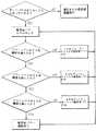
コンピュータ18は、前記真空センサ24からの信号によってぜん動ポンプ14の出力ライン42の真空レベルをプリセットするように応答する。ハンドピース30の閉塞−非閉塞状態に対応した制御ユニットの作動は図3のフローダイヤグラムに図示されている。The
The
図3に示すように、ハンドピースの吸引ライン38が閉塞されていれば、真空センサ24によって検出される真空レベルは高くなるであろう。コンピュータ18はオペレータが設定できる吸引割合、真空レベルおよび超音波パワーレベルについての限界を有する。図3に図示されているように、真空センサ24によって検出された真空レベルが、ハンドピース吸引ライン38の閉塞の結果として所定のレベルに達すると、コンピュータ18はポンプ速度コントローラ20にぜん動ポンプ14の速度を変えることを指示し、これによって吸引割合が変化する。ハンドピース30を閉塞する物質の特性に依存して、ぜん動ポンプ14の速度は増大されるか、或いは減少されるということが考慮されるべきである。閉塞物質が壊れた場合、真空センサ24が、真空レベルの低下を記録すると、コンピュータ18はぜん動ポンプ14の速度を非閉塞作動速度に変える。 As shown in FIG. 3, if the
ぜん動ポンプ14の速度を変えることによって吸引割合という水晶体超音波吸引パラメータを変えることに加えて、超音波パワー源16をハンドピースの閉塞又は非閉塞状態の関数として変えることができる。図4は、コンピュータ18とパワーレベルコントローラ22による超音波パワー源のパワーレベルの制御をフローダイヤグラムの形式で図示している。図4のフローダイヤグラムは図3のフローダイヤグラムに対応しているが水晶体超音波吸引パラメータが超音波パワーレベルに変更されていることに注目すべきである。 In addition to changing the lens ultrasound suction parameter, suction rate, by changing the speed of the
図5を参照すると、選択されたパワーレベルの関数として可変デューティサイクルを生成する超音波パワー源16の制御を示すフローダイヤグラムが図示されている。図5に示すように、かつあくまでも例示にすぎないが、33%デューティサイクルはパワーレベルがプリセット閾値、この場合33%、を越えるまで実行される。この閾値に達した時点で、デューティサイクルは超音波パワーレベルが50%閾値を越えるまで50%に増大され、50%閾値に達するとデューティサイクルは66%に増大される。超音波パワーレベルが66%閾値を越えると、パワー源は連続運転、つまり100%デューティサイクルで駆動される。図5では、33,50および66%が図示されているが、他のパーセントレベルを異なるデューティサイクル移行点を規定するために選択することができる。 Referring to FIG. 5, a flow diagram illustrating the control of the
このように、本実施の形態によれば、パルス化された超音波を供給する超音波源を備えた水晶体超音波吸引装置を操作するに際して、操作者の経験と能力によって異なるであろう操作に役立つようにプログラムすることができる。すなわち、水晶体超音波吸引手術の場合の流体および超音波の制御システムの複雑性を考慮した場合、手術者は、手術者の経験と能力によって異なるであろう手術の仕方および特殊なテクニックの両方の必要性に役立つようにプログラムすることができる。 As described above, according to the present embodiment, when operating a lens ultrasonic suction device including an ultrasonic source that supplies pulsed ultrasonic waves, the operation may vary depending on the experience and ability of the operator. Can be programmed to help. That is, considering the complexity of the fluid and ultrasound control systems in the case of phacosurgery, the surgeon will be able to use both surgical methods and specialized techniques that will vary depending on the surgeon's experience and ability. Can be programmed to serve the need.
図2に戻ると、本発明にかかる水晶体超音波吸引装置の他の実施例50が図示されており、図1に示した装置10の全ての要素は図1に示す要素同定用の参照番号と同じ番号で統合されている。
洗浄流体源32に加えて、第2の洗浄流体源33が設けられ、これら流体源32と33はハンドピース30に入るライン34にライン32a,33aを介して連結されている。バルブ35は、ライン35aを介してパワーレベルコントローラ22から送られる信号に応答して、ライン32aと流体源32およびライン33aと流体源33を交互にハンドピース30に連結する。Returning to FIG. 2, another
In addition to the cleaning
図示の如く、洗浄流体源32,33はハンドピースの上方において異なる高さに配置されており、この配置によって洗浄流体をハンドピースに複数の圧力で導入する手段を構成しており、ここでは、容器33の流体のヘッドは容器32の流体のヘッドより高くなっている。異なる長さのライン44,46を含むハーネス42は、支持体48に取付けられた状態において、容器32,33をハンドピース30上方の異なる高さに配置する手段を提供する。
種々の高さでの洗浄流体容器の使用は、洗浄流体を異なる圧力で供給する手段の代表的なものであるが、これとは別に、例えば、別個の循環ループ(図示せず)を構成する個別のポンプを設け、パワーコントローラ22からの命令により異なる圧力で洗浄流体をハンドピース30に供給するようにすることができる。As shown, the cleaning
The use of cleaning fluid containers at various heights is representative of the means for supplying cleaning fluid at different pressures, but alternatively comprises, for example, a separate circulation loop (not shown). A separate pump can be provided to supply cleaning fluid to the
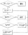
図6を参照して、ハンドピース吸引ライン38が閉塞されると、真空センサ24によって検知される真空レベルは増大する。コンピュータ18は洗浄流体源32,33のいずれがハンドピース30に連結されるべきかを制御するためのオペレータが設定できる限界値を有する。図では、2つの洗浄流体源32,33即ち容器が示されているが、任意の数の容器を用いることができることが考慮されるべきである。
図6に示すように、真空センサ24による真空レベルが吸引ハンドピースライン38の閉塞の結果として、所定のレベルに達すると、コンピュータはバルブ35を制御し、容器32,33の各々とハンドピース30との間の流体接続を制御する。Referring to FIG. 6, when the
As shown in FIG. 6, when the vacuum level by the
前述したように、ハンドピース30を閉塞している物質の性質および医師の必要性およびテクニックに依存して、ハンドピースに供給される洗浄流体の圧力は増加され、或いは減少される。物質で閉塞されると、真空センサ24は真空レベルの低下を記録し、バルブ35を作動して、非閉塞状態のレベルの圧力を与える容器32,33に切替える。上で注記した如く、本発明において、1つ以上の容器を用いることができ、例えば3個の容器(図示せず)とこれら3つの容器のいずれか1つの洗浄流体を選択するように相互連結するバルブを図2の容器系との関係で設けるようにしてもよい。 As described above, depending on the nature of the material occluding the
以上では、流体の吸引を制御する方法、洗浄流体を制御する方法、水晶体超音波吸引を操作する方法、水晶体超音波吸引システムの制御方法並びに水晶体超音波吸引装置を本発明にしたがって、本発明が有利に用いることができる様子を図示する目的で記述したが、本発明はこれに限定されるものではない。したがって、いずれのおよび全ての修正、変更、当業者が行う等価な構造は添付のクレームにおいて定義された本発明の範囲に属すると考えられるべきである。 In the above, according to the present invention, a method for controlling the suction of fluid, a method for controlling a cleaning fluid, a method for operating a lens ultrasonic suction, a method for controlling a lens ultrasonic suction system, and a lens ultrasonic suction device Although described for the purpose of illustrating how it can be used advantageously, the present invention is not limited to this. Accordingly, any and all modifications, changes, and equivalent structures made by those skilled in the art should be considered to be within the scope of the invention as defined in the appended claims.
このように、本発明は、以上の実施態様に限定されるものではなく、その要旨を逸脱しない範囲において、種々の変更や改良を加え得るものであることは言うまでもない。 Thus, it goes without saying that the present invention is not limited to the above-described embodiments, and various changes and improvements can be added without departing from the scope of the invention.
10,50…水晶体超音波吸引装置
12…制御ユニット
14…ぜん動ポンプ
16…超音波パワー源
18…コンピュータ
20…ポンプ速度コントローラ
22…パワーレベルコントローラ
24…真空センサ
32…洗浄流体源
DESCRIPTION OF
Claims (7)
Translated fromJapanese該ハンドピースに洗浄流体を供給する手段と;
真空によって上記ハンドピースから洗浄流体を吸引するためハンドピースと流体的に連通するように接続された可変速ポンプと;
上記ハンドピースに超音波を供給する超音波パワー源と;
上記ハンドピース内の真空度を検知するため該ハンドピースと流体的に連通するように接続されたセンサと;
上記ハンドピース内の検出された真空度に応じて、上記超音波パワー源によりハンドピースに供給される超音波の強度レベルを変化させるコンピュータ制御ユニットと;
を備えたことを特徴とする水晶体超音波吸引装置。
A handpiece for ultrasonic suction of the lens;
Means for supplying cleaning fluid to the handpiece;
A variable speed pump connected in fluid communication with the handpiece to aspirate cleaning fluid from the handpiece by vacuum;
An ultrasonic power source for supplying ultrasonic waves to the handpiece;
A sensor connected in fluid communication with the handpiece to detect a degree of vacuum in the handpiece;
A computer control unit that changes an intensity level of ultrasonic waves supplied to the handpiece by the ultrasonic power source in accordance with a detected degree of vacuum in the handpiece;
A lens ultrasonic suction device comprising:
2. The crystalline lens according to claim 1, wherein the control unit changes a duty cycle of an ultrasonic wave supplied to the handpiece by the ultrasonic power source in accordance with a detected degree of vacuum in the handpiece. Ultrasonic suction device.
該バルブ手段は該制御ユニットによって制御されるとともに、該制御ユニットは、上記ハンドピース内の検知された真空度に応じて、上記バルブ手段をして、1つの選択された洗浄流体供給手段を上記ハンドピースに流体的に連通させる、
ことを特徴とする請求項1記載の水晶体超音波吸引装置。
The means for supplying the cleaning fluid to the handpiece includes a plurality of units disposed at different heights above the handpiece and valve means for fluidly communicating one selected cleaning fluid supply means to the handpiece. Including a cleaning fluid supply means,
The valve means is controlled by the control unit, and the control unit controls the valve means according to the detected degree of vacuum in the handpiece, and selects one selected cleaning fluid supply means. Fluidly communicate with the handpiece,
The phacoemulsification device according to claim 1.
超音波パワー源と、
流体吸引用真空源と、
洗浄流体源と、
上記ハンドピースに供給される超音波とハンドピースからの洗浄流体の吸引を制御するための真空センサを有する制御ユニットとを備え、
上記制御ユニットは、一連の指示を有する媒体であって、コンピュータで使用出来る媒体等のコンピュータプログラム製品を有し、
該一連の指示は、プロセッサにより実行されると、該プロセッサをして、上記超音波パワー源を制御するためのプロセスを実行させることを特徴とする水晶体超音波吸引システムであって、
該プロセスは、
(a)上記水晶体超音波吸引システムが動作する間、上記ハンドピースへ超音波を供給するように上記超音波パワー源を制御するステップと;
(b)上記洗浄流体を吸引する間、ハンドピースの閉塞状態に対応するハンド
ピース内の真空度を検知するステップと;
(c)ハンドピースの閉塞状態に対応するハンドピース内の検知された真空度
に応じて、上記ハンドピースに供給される超音波を可変制御するステッ
プ;
を含むことを特徴とする水晶体超音波吸引システム。
A handpiece for ultrasonic suction of the lens,
An ultrasonic power source,
A vacuum source for fluid suction;
A source of cleaning fluid;
A control unit having an ultrasonic wave supplied to the handpiece and a vacuum sensor for controlling the suction of the cleaning fluid from the handpiece;
The control unit is a medium having a series of instructions, and has a computer program product such as a medium usable by a computer,
The series of instructions, when executed by a processor, causes the processor to perform a process for controlling the ultrasonic power source, comprising:
The process
(A) controlling the ultrasonic power source to supply ultrasonic waves to the handpiece while the crystalline ultrasound system is operating;
(B) detecting the degree of vacuum in the handpiece corresponding to the closed state of the handpiece while aspirating the cleaning fluid;
(C) variably controlling the ultrasonic wave supplied to the handpiece according to the degree of vacuum detected in the handpiece corresponding to the closed state of the handpiece;
A lens ultrasonic suction system comprising:
The variable control step increases the intensity of the ultrasonic wave supplied to the handpiece according to the detected degree of vacuum in the handpiece corresponding to the closed state of the handpiece.4. Lens ultrasonic suction system according to 4.
The variable control step reduces the intensity of ultrasonic waves supplied to the handpiece according to a detected degree of vacuum in the handpiece corresponding to the closed state of the handpiece.4. Lens ultrasonic suction system according to 4.
(a)上記超音波の強度レベルが第1の閾値を超えるまでは、上記超音波の
デューティサイクルが第1のデューティサイクルとなるように、上記超
音波パワー源の出力を設定するステップと;
(b)上記超音波の強度レベルが、第1の閾値より大きい第2の閾値を超
えるまでは、上記超音波のデューティサイクルが第1のデューティサイ
クルより大きい第2のデューティサイクルとなるように、上記超音波パ
ワー源の出力を設定するステップと;
(c)上記超音波の強度レベルが、第2の閾値よりさらに大きい第3の閾値を
超えるまでは、上記超音波のデューティサイクルが第2のデューテ
ィサイクルより大きい第3のデューティサイクルとなるように、上記超
音波パワー源の出力を設定するステップと;
(d)その後、上記超音波のデューティサイクルが、第3のデューティサイク
ルより大きいデューティサイクルとなるように、上記超音波パワー源の
出力を設定するステップ;
の一連のステップを含むことを特徴とする請求項4記載の水晶体超音波吸引システム。
Controlling the ultrasonic power source to supply ultrasonic waves to the handpiece comprises:
(A) setting the output of the ultrasonic power source so that the ultrasonic duty cycle is the first duty cycle until the ultrasonic intensity level exceeds a firstthreshold ;
(B) the ultrasonic wave intensity level, the firstthreshold larger than the secondthreshold value super
Until the output of the ultrasonic power source is such that the ultrasonic duty cycle is a second duty cycle greater than the first duty cycle;
(C) a thirdthreshold value where the intensity level of the ultrasonic wave is larger than the secondthresholdvalue ;
Setting the output of the ultrasonic power source until the ultrasonic duty cycle is a third duty cycle that is greater than the second duty cycle, until
(D) then setting the output of the ultrasonic power source so that the duty cycle of the ultrasonic wave is greater than a third duty cycle;
The phacoemulsification system according to claim4 , comprising a series of steps.
Applications Claiming Priority (2)
| Application Number | Priority Date | Filing Date | Title |
|---|---|---|---|
| US08/188,188US5591127A (en) | 1994-01-28 | 1994-01-28 | Phacoemulsification method and apparatus |
| US08/378,533US5700240A (en) | 1994-01-28 | 1995-01-24 | Phacoemulsification system having ultrasonic power controlled by aspiration vacuum sensor |
Related Parent Applications (1)
| Application Number | Title | Priority Date | Filing Date |
|---|---|---|---|
| JP2000340298ADivisionJP3561227B2 (en) | 1994-01-28 | 2000-11-08 | Control method of lens ultrasonic suction device |
Publications (2)
| Publication Number | Publication Date |
|---|---|
| JP2004209276A JP2004209276A (en) | 2004-07-29 |
| JP4063785B2true JP4063785B2 (en) | 2008-03-19 |
Family
ID=26883821
Family Applications (3)
| Application Number | Title | Priority Date | Filing Date |
|---|---|---|---|
| JP52023295AExpired - LifetimeJP3162723B2 (en) | 1994-01-28 | 1995-01-26 | Apparatus for controlling fluid irrigation and fluid aspiration in ophthalmic surgery |
| JP2000340298AExpired - LifetimeJP3561227B2 (en) | 1994-01-28 | 2000-11-08 | Control method of lens ultrasonic suction device |
| JP2004087335AExpired - LifetimeJP4063785B2 (en) | 1994-01-28 | 2004-03-24 | Method of controlling lens ultrasonic suction system and lens ultrasonic suction device |
Family Applications Before (2)
| Application Number | Title | Priority Date | Filing Date |
|---|---|---|---|
| JP52023295AExpired - LifetimeJP3162723B2 (en) | 1994-01-28 | 1995-01-26 | Apparatus for controlling fluid irrigation and fluid aspiration in ophthalmic surgery |
| JP2000340298AExpired - LifetimeJP3561227B2 (en) | 1994-01-28 | 2000-11-08 | Control method of lens ultrasonic suction device |
Country Status (4)
| Country | Link |
|---|---|
| EP (1) | EP0741554B1 (en) |
| JP (3) | JP3162723B2 (en) |
| DE (2) | DE69534254T2 (en) |
| WO (1) | WO1995020374A1 (en) |
Families Citing this family (39)
| Publication number | Priority date | Publication date | Assignee | Title |
|---|---|---|---|---|
| US5766146A (en)* | 1996-04-04 | 1998-06-16 | Allergan | Method of infusion control during phacoemulsification surgery |
| US5754016A (en)* | 1996-09-18 | 1998-05-19 | Dentsply Research & Development Corp | Method of continuous control of tip vibration in a dental scalar system |
| US6780165B2 (en) | 1997-01-22 | 2004-08-24 | Advanced Medical Optics | Micro-burst ultrasonic power delivery |
| US7169123B2 (en) | 1997-01-22 | 2007-01-30 | Advanced Medical Optics, Inc. | Control of pulse duty cycle based upon footswitch displacement |
| US6179808B1 (en)* | 1999-06-18 | 2001-01-30 | Alcon Laboratories, Inc. | Method of controlling the operating parameters of a surgical system |
| BR0011764A (en)* | 1999-06-18 | 2003-07-08 | Alcon Mfg Ltd | Infusion Control System |
| US7077820B1 (en) | 2002-10-21 | 2006-07-18 | Advanced Medical Optics, Inc. | Enhanced microburst ultrasonic power delivery system and method |
| US7316664B2 (en) | 2002-10-21 | 2008-01-08 | Advanced Medical Optics, Inc. | Modulated pulsed ultrasonic power delivery system and method |
| JP4162544B2 (en) | 2003-01-15 | 2008-10-08 | 株式会社ニデック | Ultrasonic surgical device |
| EP2604235A1 (en) | 2003-03-12 | 2013-06-19 | Abbott Medical Optics Inc. | System and method for pulsed ultrasonic power delivery employing cavitation effects |
| JP4126253B2 (en) | 2003-06-25 | 2008-07-30 | 株式会社ニデック | Ultrasonic surgical device |
| US7846126B2 (en) | 2003-07-14 | 2010-12-07 | Abbott Medical Optics, Inc. | System and method for modulated surgical procedure irrigation and aspiration |
| US7625388B2 (en) | 2004-03-22 | 2009-12-01 | Alcon, Inc. | Method of controlling a surgical system based on a load on the cutting tip of a handpiece |
| US7811255B2 (en)* | 2004-03-22 | 2010-10-12 | Alcon, Inc. | Method of controlling a surgical system based on a rate of change of an operating parameter |
| US7645255B2 (en)* | 2004-03-22 | 2010-01-12 | Alcon, Inc. | Method of controlling a surgical system based on irrigation flow |
| ATE529848T1 (en)* | 2004-04-15 | 2011-11-15 | Novartis Ag | SYSTEM FOR GUIDING REMOVAL OF CATARACT TISSUE |
| US7670330B2 (en)* | 2005-03-21 | 2010-03-02 | Abbott Medical Optics Inc. | Application of vacuum as a method and mechanism for controlling eye chamber stability |
| US7785316B2 (en) | 2005-03-21 | 2010-08-31 | Abbott Medical Optics Inc. | Application of a system parameter as a method and mechanism for controlling eye chamber stability |
| US20070000301A1 (en)* | 2005-06-21 | 2007-01-04 | Todd Kirk W | Reflux control in microsurgical system |
| US7713237B2 (en)* | 2005-09-28 | 2010-05-11 | Alcon, Inc. | Surgical cassette for intraocular pressure control |
| US7785336B2 (en) | 2006-08-01 | 2010-08-31 | Abbott Medical Optics Inc. | Vacuum sense control for phaco pulse shaping |
| WO2008129081A1 (en)* | 2007-04-20 | 2008-10-30 | Luis Emilio Abad | System for detached retina operations |
| JP5301936B2 (en)* | 2008-09-30 | 2013-09-25 | 株式会社ニデック | Ultrasonic surgical device |
| US8623040B2 (en) | 2009-07-01 | 2014-01-07 | Alcon Research, Ltd. | Phacoemulsification hook tip |
| DE102009049430B4 (en)* | 2009-10-14 | 2015-07-09 | Carl Zeiss Meditec Ag | Ophthalmic surgical measuring device, ophthalmic surgical system and associated method |
| US8136779B2 (en) | 2010-07-27 | 2012-03-20 | Alcon Research, Ltd. | Mounting arrangement for a pressurized irrigation system |
| US10258505B2 (en) | 2010-09-17 | 2019-04-16 | Alcon Research, Ltd. | Balanced phacoemulsification tip |
| DE102010047012B4 (en)* | 2010-09-30 | 2015-12-31 | Carl Zeiss Meditec Ag | Control device for an ophthalmic surgical system |
| DE102010047009B4 (en)* | 2010-09-30 | 2018-12-06 | Carl Zeiss Meditec Ag | Control device for an ophthalmic surgical system |
| US9050627B2 (en) | 2011-09-02 | 2015-06-09 | Abbott Medical Optics Inc. | Systems and methods for ultrasonic power measurement and control of phacoemulsification systems |
| US11071816B2 (en) | 2017-10-04 | 2021-07-27 | Johnson & Johnson Surgical Vision, Inc. | System, apparatus and method for monitoring anterior chamber intraoperative intraocular pressure |
| EP3691585B1 (en) | 2017-10-04 | 2023-09-27 | Johnson & Johnson Surgical Vision, Inc. | Systems for measuring fluid flow in a venturi based system |
| WO2019069189A1 (en) | 2017-10-04 | 2019-04-11 | Johnson & Johnson Surgical Vision, Inc. | A system and method to augment irrigation pressure and to maintain iop during post occlusion surge |
| US11969380B2 (en) | 2017-10-04 | 2024-04-30 | Johnson & Johnson Surgical Vision, Inc. | Advanced occlusion management methods for a phacoemulsification system |
| US11957620B2 (en) | 2018-10-03 | 2024-04-16 | Johnson & Johnson Surgical Vision, Inc. | Learning auto phaco phacoemulsification mode for ophthalmic surgery |
| US11141313B2 (en) | 2018-10-03 | 2021-10-12 | Johnson & Johnson Surgical Vision, Inc. | Systems and methods for automated phacoemulsification |
| US11877953B2 (en) | 2019-12-26 | 2024-01-23 | Johnson & Johnson Surgical Vision, Inc. | Phacoemulsification apparatus |
| US12285360B2 (en) | 2020-12-22 | 2025-04-29 | Johnson & Johnson Surgical Vision, Inc. | Reducing irrigation/aspiration valve response time in a phacoemulsification system |
| US20230039808A1 (en) | 2021-08-07 | 2023-02-09 | Johnson & Johnson Surgical Vision, Inc. | Electronically detecting phacoemulsification tip engagement with a lens |
Family Cites Families (6)
| Publication number | Priority date | Publication date | Assignee | Title |
|---|---|---|---|---|
| US3812855A (en)* | 1971-12-15 | 1974-05-28 | Surgical Design Corp | System for controlling fluid and suction pressure |
| US4168707A (en)* | 1977-06-13 | 1979-09-25 | Douvas Nicholas G | Control apparatus for microsurgical instruments |
| EP0226622A4 (en)* | 1985-06-05 | 1988-08-23 | Coopervision Inc | Connection fitting for a fluid flow regulation system. |
| US4827911A (en)* | 1986-04-02 | 1989-05-09 | Cooper Lasersonics, Inc. | Method and apparatus for ultrasonic surgical fragmentation and removal of tissue |
| US5279547A (en)* | 1991-01-03 | 1994-01-18 | Alcon Surgical Inc. | Computer controlled smart phacoemulsification method and apparatus |
| US5242404A (en)* | 1992-02-12 | 1993-09-07 | American Cyanamid Company | Aspiration control system |
- 1995
- 1995-01-26DEDE69534254Tpatent/DE69534254T2/ennot_activeExpired - Lifetime
- 1995-01-26WOPCT/US1995/001224patent/WO1995020374A1/enactiveSearch and Examination
- 1995-01-26EPEP95910897Apatent/EP0741554B1/ennot_activeExpired - Lifetime
- 1995-01-26JPJP52023295Apatent/JP3162723B2/ennot_activeExpired - Lifetime
- 1995-01-26DEDE69528964Tpatent/DE69528964T2/ennot_activeExpired - Lifetime
- 2000
- 2000-11-08JPJP2000340298Apatent/JP3561227B2/ennot_activeExpired - Lifetime
- 2004
- 2004-03-24JPJP2004087335Apatent/JP4063785B2/ennot_activeExpired - Lifetime
Also Published As
| Publication number | Publication date |
|---|---|
| EP0741554B1 (en) | 2002-11-27 |
| DE69528964T2 (en) | 2003-10-09 |
| DE69528964D1 (en) | 2003-01-09 |
| JPH09508298A (en) | 1997-08-26 |
| JP2004209276A (en) | 2004-07-29 |
| EP0741554A1 (en) | 1996-11-13 |
| JP3561227B2 (en) | 2004-09-02 |
| JP2001161740A (en) | 2001-06-19 |
| DE69534254T2 (en) | 2005-10-27 |
| JP3162723B2 (en) | 2001-05-08 |
| WO1995020374A1 (en) | 1995-08-03 |
| DE69534254D1 (en) | 2005-07-07 |
Similar Documents
| Publication | Publication Date | Title |
|---|---|---|
| JP4063785B2 (en) | Method of controlling lens ultrasonic suction system and lens ultrasonic suction device | |
| US5700240A (en) | Phacoemulsification system having ultrasonic power controlled by aspiration vacuum sensor | |
| US5766146A (en) | Method of infusion control during phacoemulsification surgery | |
| EP2758015B1 (en) | Systems and methods for controlling vacuum within phacoemulsification systems | |
| EP1832259B1 (en) | Pulse amplitude manipulation for controlling a phacoemulsification surgical system | |
| WO2019089203A1 (en) | Automatic ultrasonic phacoemulsification control | |
| AU2020333241A1 (en) | Systems and method for smart phaco in surgical systems |
Legal Events
| Date | Code | Title | Description |
|---|---|---|---|
| A521 | Request for written amendment filed | Free format text:JAPANESE INTERMEDIATE CODE: A821 Effective date:20040415 | |
| RD02 | Notification of acceptance of power of attorney | Free format text:JAPANESE INTERMEDIATE CODE: A7422 Effective date:20040415 | |
| A521 | Request for written amendment filed | Free format text:JAPANESE INTERMEDIATE CODE: A821 Effective date:20040416 | |
| RD04 | Notification of resignation of power of attorney | Free format text:JAPANESE INTERMEDIATE CODE: A7424 Effective date:20040416 | |
| A621 | Written request for application examination | Free format text:JAPANESE INTERMEDIATE CODE: A621 Effective date:20040423 | |
| A131 | Notification of reasons for refusal | Free format text:JAPANESE INTERMEDIATE CODE: A131 Effective date:20060912 | |
| A521 | Request for written amendment filed | Free format text:JAPANESE INTERMEDIATE CODE: A523 Effective date:20061212 | |
| A521 | Request for written amendment filed | Free format text:JAPANESE INTERMEDIATE CODE: A523 Effective date:20070117 | |
| A131 | Notification of reasons for refusal | Free format text:JAPANESE INTERMEDIATE CODE: A131 Effective date:20070227 | |
| A601 | Written request for extension of time | Free format text:JAPANESE INTERMEDIATE CODE: A601 Effective date:20070523 | |
| A602 | Written permission of extension of time | Free format text:JAPANESE INTERMEDIATE CODE: A602 Effective date:20070531 | |
| A601 | Written request for extension of time | Free format text:JAPANESE INTERMEDIATE CODE: A601 Effective date:20070614 | |
| A602 | Written permission of extension of time | Free format text:JAPANESE INTERMEDIATE CODE: A602 Effective date:20070619 | |
| A601 | Written request for extension of time | Free format text:JAPANESE INTERMEDIATE CODE: A601 Effective date:20070725 | |
| A602 | Written permission of extension of time | Free format text:JAPANESE INTERMEDIATE CODE: A602 Effective date:20070730 | |
| A521 | Request for written amendment filed | Free format text:JAPANESE INTERMEDIATE CODE: A523 Effective date:20070827 | |
| TRDD | Decision of grant or rejection written | ||
| A01 | Written decision to grant a patent or to grant a registration (utility model) | Free format text:JAPANESE INTERMEDIATE CODE: A01 Effective date:20071218 | |
| A61 | First payment of annual fees (during grant procedure) | Free format text:JAPANESE INTERMEDIATE CODE: A61 Effective date:20071225 | |
| R150 | Certificate of patent or registration of utility model | Free format text:JAPANESE INTERMEDIATE CODE: R150 | |
| FPAY | Renewal fee payment (event date is renewal date of database) | Free format text:PAYMENT UNTIL: 20110111 Year of fee payment:3 | |
| FPAY | Renewal fee payment (event date is renewal date of database) | Free format text:PAYMENT UNTIL: 20110111 Year of fee payment:3 | |
| FPAY | Renewal fee payment (event date is renewal date of database) | Free format text:PAYMENT UNTIL: 20120111 Year of fee payment:4 | |
| FPAY | Renewal fee payment (event date is renewal date of database) | Free format text:PAYMENT UNTIL: 20130111 Year of fee payment:5 | |
| R250 | Receipt of annual fees | Free format text:JAPANESE INTERMEDIATE CODE: R250 | |
| R250 | Receipt of annual fees | Free format text:JAPANESE INTERMEDIATE CODE: R250 | |
| EXPY | Cancellation because of completion of term |