JP4063419B2 - Optical transmission system - Google Patents
Optical transmission systemDownload PDFInfo
- Publication number
- JP4063419B2 JP4063419B2JP28431098AJP28431098AJP4063419B2JP 4063419 B2JP4063419 B2JP 4063419B2JP 28431098 AJP28431098 AJP 28431098AJP 28431098 AJP28431098 AJP 28431098AJP 4063419 B2JP4063419 B2JP 4063419B2
- Authority
- JP
- Japan
- Prior art keywords
- signal
- optical
- conversion unit
- unit
- electro
- Prior art date
- Legal status (The legal status is an assumption and is not a legal conclusion. Google has not performed a legal analysis and makes no representation as to the accuracy of the status listed.)
- Expired - Fee Related
Links
Images


Classifications
- H—ELECTRICITY
- H04—ELECTRIC COMMUNICATION TECHNIQUE
- H04B—TRANSMISSION
- H04B1/00—Details of transmission systems, not covered by a single one of groups H04B3/00 - H04B13/00; Details of transmission systems not characterised by the medium used for transmission
- H04B1/02—Transmitters
- H04B1/04—Circuits
Landscapes
- Engineering & Computer Science (AREA)
- Computer Networks & Wireless Communication (AREA)
- Signal Processing (AREA)
- Optical Communication System (AREA)
- Mobile Radio Communication Systems (AREA)
- Transmitters (AREA)
Description
Translated fromJapanese【0001】
【発明の属する技術分野】
本発明は、光伝送システムに関し、より特定的には、親局と子局(前進局)とからなる無線基地局で用いられ、親局・子局間で信号を光伝送するための光伝送システムに関する。
【0002】
【従来の技術】
携帯電話、自動車電話等の移動体通信では、地下やトンネル内部など、無線基地局からの電波が到達しない不感地帯の解消が課題となる。この課題を解決するものとして、アンテナ機能を省略した親局とアンテナ機能だけを持つ複数の子局とからなる無線基地局がある。そこでは、複数の子局は、前進局として不感地帯等に分散配置され、親局と各子局とが光ファイバで接続される。親局・子局間の信号伝送は、無線信号(RF信号)を光信号に変換して伝送する光伝送方式によって行われる。
【0003】
図9は、上記の無線基地局で用いられ、親局・子局間で信号を光伝送するための従来の光伝送システムの構成の一例を示すブロック図である。この種の光伝送システムは、例えば「無線基地局用光伝送装置」(真田他 ,National Technical Report Vol.39 No.4 ,Aug.1993)に記載されている。
図9において、従来の光伝送システムは、伝送されるべき電気信号を増幅する増幅部90と、増幅部90の出力信号を電気光変換する電気光変換部91と、伝送された光信号を光電気変換する光電気変換部92とを備えている。増幅部90および電気光変換部91は、送信側に設けられ、光電気変換部92は、受信側に設けられ、電気光変換部91と光電気変換部92とが光ファイバ93で接続される。
電気光変換部91は、入力信号の電力に関し、その変化に対する出力光信号の強度の変化が線形であるような所定の線形領域を有する。すなわち、この領域の上限を超える電力の信号が電気光変換部91に入力されると、出力光信号が歪む。
光電気変換部92は、入力光信号の強度に関し、その変化に対する出力信号の電力の変化が線形であるような別の所定の線形領域を有する。すなわち、この領域の上限を超える強度の光信号が光電気変換部92に入力されると、出力信号が歪む。
増幅部90は、光電気変換部92からの出力信号の電力が雑音のそれよりも十分に大きくなるような増幅率であって、しかも、電気光変換部91への入力信号の電力が上記所定の線形領域の上限を超えることなく、かつ光電気変換部92への入力光信号の強度が上記別の所定の線形領域の上限を超えることのないような増幅率を有する。これにより、受信側では、雑音に比べて十分に大きな電力の、しかも歪みのない信号が得られる。
【0004】
ところで、「CDMA方式携帯自動車電話システム」(社団法人電波産業会 ,ARIB STD−T53 1.0版)にあるように、移動体通信では、近年、回線数の急激な増加に伴い、従来方式と比べて回線収容数の格段に大きいCDMA(符号分割多重)方式を採用することが提案された。そして、最近、CDMA方式による移動体通信が一部で実用化されており、さらに、今後、移動体通信に占めるCDMA方式の割合が増えることが予想されている。
つまり、これからCDMA方式への移行が完了するまでの期間は、現行方式とCDMA方式とが併存するので、設備コストを抑える観点から、現行方式用の既存の設備を生かしつつ、CDMA方式への対応を図ることが重要となる。
【0005】
【発明が解決しようとする課題】
そこで、上記従来の光伝送システムにおいて、現行方式で用いられるRF信号とCDMA方式で用いられる符号分割多重信号とを光伝送することを考える。この場合、受信側では、符号分割多重信号に関し、雑音に比べて十分に大きな電力の信号が得られない。なぜなら、現行方式およびCDMA方式では、それぞれ信号の電力が規格で定められているが、それらに従えば、送信側に供給される入力信号の電力は、CDMA方式で用いられる符号分割多重信号の方が、従来方式で用いられるRF信号よりも小さいからである。
なお、現行方式の規格については、「デジタル方式自動車電話システム」(財団法人電波システム開発センター ,RCR STD−27A)に、CDMA方式の規格については、上記「CDMA方式携帯自動車電話システム」に、それぞれ記載されている。また、符号分割多重信号を光伝送する装置は、例えば、特願平4−219894公報に開示されている。
【0006】
一方、符号分割多重信号に関し、雑音に比べて十分に大きな電力の信号が得られるように、増幅部90の増幅率を高く設定したとする。しかし、この場合には、RF信号に関し、電気光変換部91への入力信号の電力が上記所定の線形領域の上限を超えるか、または光電気変換部92への入力光信号の強度が上記別の所定の線形領域の上限を超え、その結果、受信側で得られる信号が歪むことが予想される。
【0007】
つまり、上記従来の光伝送システムにおいて、RF信号と符号分割多重信号とを光伝送した場合、増幅部90の増幅率をどう設定しても、RF信号および符号分割多重信号の両方に関し、受信側で、雑音に比べて十分に大きな電力の、しかも歪みのない信号を得られるようにはできない。なお、付言すれば、上記特願平4−219894号公報には、RF信号および符号分割多重信号の両方を光伝送することは記載されていない。
【0008】
それゆえに、本発明の目的は、例えば親局と1以上の子局とからなる無線基地局で用いられ、RF信号および符号分割多重信号を含む信号を、RF信号および符号分割多重信号の両方に関し、受信側で、雑音に比べて十分に大きな電力の、しかも歪みのない信号が得られるように、光伝送することができる光伝送システムを提供することである。
【0034】
【課題を解決するための手段および発明の効果】
上記第1の発明は、送信電力が互いに異なるTDMA方式で用いられる無線信号、及びCDMA方式で用いられる符号分割多重信号を電気光変換し、当該変換した光信号を光ファイバで送信する光送信装置であって、
無線信号を、無線信号の電力に基づいた増幅率で増幅する第1の増幅部と、
符号分割多重信号を、符号分割多重信号の電力に基づいた増幅率で増幅する第2の増幅部と、
第1の増幅部で増幅された無線信号を電気光変換して、第1の光信号を生成する第1の電気光変換部と、
第2の増幅部で増幅された符号分割多重信号を電気光変換して、第2の光信号を生成する第2の電気光変換部と、
第1の電気光変換部が変換して得られた第1の光信号と、第2の電気光変換部が変換して得られた第2の光信号とを波長多重する波長多重部とを備え、
第1の増幅部は、第1の電気光変換部への入力信号の電力が当該第1の電気光変換部の線形領域の上限を超えないような増幅率で増幅を行い、
第2の増幅部は、第2の電気光変換部への入力信号の電力が当該第2の電気光変換部の線形領域の上限を超えないような増幅率で増幅を行うことを特徴とする。
【0036】
上記第1の発明では、RF信号および符号分割多重信号を伝送する際に、それぞれの信号電力に基づいた増幅率で増幅して伝送するので、受信側で得られるRF信号と符号分割多重信号とを、共に雑音に比べて十分に大きな電力を持つようにできる。
【0038】
また、上記第1の発明では、受信側で得られるRF信号と符号分割多重信号とを、共に、電気光変換時に歪みを生じさせることなく、雑音に比べて十分に大きな電力を持つようにできる。
【0039】
第2の発明は、第1の発明において、光送信装置への入力信号は無線信号と符号分割多重信号とを含んでおり、
無線信号の周波数帯域と、符号分割多重信号の周波数帯域とは、互いに異なっており、
光送信装置は、さらに、入力信号を無線信号と符号分割多重信号とに分離する分離部を含むことを特徴としている。
【0040】
上記第2の発明では、RF信号および符号分割多重信号を含む入力信号を伝送する際に、その入力信号をRF信号と符号分割多重信とに分離して、それぞれの信号電力に基づいた増幅率で増幅して伝送するので、受信側で得られるRF信号と符号分割多重信号とを、共に雑音に比べて十分に大きな電力を持つようにできる。
【0041】
第3の発明は、第1の発明又は第2の発明において、光信号を光ファイバで送信する光送信装置と、光信号を受信する光受信装置とからなる光伝送システムであって、
光送信装置は、請求項1又は2に記載の光送信装置であって、
光受信装置は、
波長多重部の出力光信号を、第1の光信号と第2の光信号とに波長分離する波長分離部と、
第1の光信号を光電気変換する第1の光電気変換部と、
第2の光信号を光電気変換する第2の光電気変換部とを備える。
【0042】
上記第3の発明では、第1の発明又は第2の発明の光送信装置を光受信装置を備えた光伝送システムに応用することができる。
【0043】
第4の発明は、第3の発明において、第1の増幅部は、さらに、第1の光電気変換部への入力光信号の強度が当該第1の光電気変換部の線形領域の上限を超えないような増幅率で増幅を行い、
第2の増幅部は、さらに、第2の光電気変換部への入力光信号の強度が当該第2の光電気変換部の線形領域の上限を超えないような増幅率で増幅を行うことを特徴とする。
【0044】
上記第4の発明では、受信側で得られるRF信号と符号分割多重信号とを、共に、光電気変換時に、または電気光変換時および光電気変換時に、歪みを生じさせることなく、雑音に比べて十分に大きな電力を持つようにできる。
【0045】
上記第5の発明は、第1の発明又は第2の発明において、光信号を光ファイバで送信する光送信装置と、光信号を受信する光受信装置とからなる光伝送システムであって、
光送信装置は、請求項1又は2に記載の光送信装置であって、
光受信装置は、
波長多重部の出力光信号を、光電気変換する光電気変換部と、
光電気変換部の出力電気信号を、周波数分離して、RF信号と符号分割多重信号とに分離する分離部とを備える。
【0046】
上記第5の発明では、第1の発明又は第2の発明の光送信装置を光受信装置を備えた光伝送システムに応用することができる。
【0047】
第6の発明は、第5の発明において、第1の増幅部は、さらに、第1の光電気変換部への入力光信号の強度が当該第1の光電気変換部の線形領域の上限を超えないような増幅率で増幅を行い、
第2の増幅部は、さらに、第2の光電気変換部への入力光信号の強度が当該第2の光電気変換部の線形領域の上限を超えないような増幅率で増幅を行うことを特徴とする。
【0048】
上記第6の発明では、受信側で得られるRF信号と符号分割多重信号とを、共に、光電気変換時に、または電気光変換時および光電気変換時に、歪みを生じさせることなく、雑音に比べて十分に大きな電力を持つようにできる。
【0051】
【発明の実施の形態】
以下、本発明の実施の形態について、図面を参照しながら説明する。
(第1の実施形態)
図1は、本発明の第1の実施形態に係る光伝送システムの構成を示すブロック図である。図1において、光伝送システムは、分離部10と、増幅部11および12と、合波部13と、電気光変換部14と、光電気変換部15とを備えている。分離部10、増幅部11および12、合波部13および電気光変換部14は、送信側に設けられ、光電気変換部15は、受信側に設けられる。
【0052】
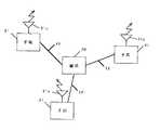
図2は、図1のシステムが適用される、現行方式およびCDMA方式の両方式による移動体通信を行うための無線基地局の一例を示す模式図である。図2において、無線基地局は、アンテナ21aを省略した親局20と、アンテナ21aを持つ1以上の子局21とからなる。1以上の子局21は、前進局として不感地帯等に分散配置され、親局20と各子局21とが光ファイバ22で接続される。
図1の光伝送システムは、図2の無線基地局に適用されて、親局20・子局21間の信号伝送を行う。すなわち、現行方式で用いられるRF信号(例えば周波数多重分割アクセス信号など、符号分割多重信号とは異なる移動体通信用無線信号;以下同様)、およびCDMA方式で用いられる符号分割多重信号を含む入力信号を光信号に変換して、光ファイバ22を通じて伝送する。
【0053】
再び図1において、分離部10は、入力信号を、RF信号と符号分割多重信号とに分離する。増幅部11は、伝送されるべきRF信号を増幅する。増幅部121は、伝送されるべき符号分割多重信号を増幅する。合波部13は、増幅されたRF信号と増幅された符号分割多重信号とを合波(周波数多重)する。電気光変換部14は、合波部13の出力信号を電気光変換する。光電気変換部15は、伝送された光信号(電気光変換部14の出力光信号)を光電気変換する。
【0054】
電気光変換部14は、入力信号の電力に関し、その変化に対する出力光信号の強度の変化が線形であるような所定の線形領域を有する。すなわち、この領域の上限を超える電力の信号が電気光変換部14に入力されると、出力光信号が歪む。
光電気変換部15は、入力光信号の強度に関し、その変化に対する出力信号の電力の変化が線形であるような別の所定の線形領域を有する。すなわち、この領域の上限を超える強度の光信号が光電気変換部15に入力されると、出力信号が歪む。
【0055】
増幅部11は、光電気変換部15からの出力信号に含まれるRF信号の電力が雑音のそれよりも十分に大きくなるような増幅率で増幅を行う。それにより、受信側では、雑音に比べて十分に大きな電力の(つまりC/N比の良好な)RF信号が得られる。
最も好ましくは、増幅部11は、上記の増幅率であって、しかも、電気光変換部14への入力信号の電力が上記所定の線形領域の上限を超えることなく、かつ光電気変換部15への入力光信号の強度が上記別の所定の線形領域の上限を超えることのないような増幅率で増幅を行う。それにより、受信側では、雑音に比べて十分に大きな電力の、しかも歪みのないRF信号が得られる。
【0056】
増幅部12は、光電気変換部15からの出力信号に含まれる符号分割多重信号の電力が雑音のそれよりも十分に大きくなるような増幅率で増幅を行う。それにより、受信側では、雑音に比べて十分に大きな電力の(つまりC/N比の良好な)符号分割多重信号が得られる。
最も好ましくは、増幅部12は、上記の増幅率であって、しかも、電気光変換部14への入力信号の電力が上記所定の線形領域の上限を超えることなく、かつ光電気変換部15への入力光信号の強度が上記別の所定の線形領域の上限を超えることのないような増幅率で増幅を行う。それにより、受信側では、雑音に比べて十分に大きな電力の、しかも歪みのない符号分割多重信号が得られる。
【0057】
以上のように構成された光伝送システムについて、以下、図2の無線基地局に適用された場合の動作を説明する。
最初、子局21から親局20へと信号を伝送する動作を説明する。
図3は、図1の光伝送システムが適用された図2の無線基地局の構成の一例を示すブロック図である。図3には、子局21から親局20へ信号を伝送する場合に必要な要素が示されている。図3において、アンテナ21aを備えた子局21には、図1の分離部10、増幅部11および12、合波部13および電気光変換部14が設けられ、親局20には、光電気変換部15が設けられる。
【0058】
子局21の通話エリア内には、現行方式用の移動端末と、CDMA方式用の移動端末とが混在している(図示せず)。これら移動端末側からは、子局21に向けて、RF信号と符号分割多重信号とが送信される。子局21では、アンテナ21aによって、これらRF信号および符号分割多重信号が受信され、分離部10へと入力される。分離部10は、RF信号および符号分割多重信号を含む入力信号を、RF信号と符号分割多重信号とに分離する。
【0059】
なお、分離部10は、例えば、入力信号を2分岐する分岐部と、特定の周波数の信号を選択的に透過させるフィルタとを用いて実現できる。分離部10の構成の一例を、図4に示す。図4において、分離部10は、分岐部40およびフィルタ41および42を含む。フィルタ41は、その透過帯域がRF信号用の帯域を含み、かつ符号分割多重信号用の帯域を含まないような特性を有するフィルタである。フィルタ42は、その透過帯域が符号分割多重信号用の帯域を含み、かつRF信号用の帯域を含まないような特性を有するフィルタである。従って、RF信号および符号分割多重信号が分岐部40へと入力されると、フィルタ41からはRF信号が、フィルタ42からは符号分割多重信号がそれぞれ出力される。
また、アンテナ21aおよび分離部10に代えて、RF信号用のアンテナおよび符号分割多重信号用のアンテナを設けても、入力信号を2分岐することができる。つまり、RF信号用のアンテナおよび符号分割多重信号用のアンテナによって、上記と同様の信号分離機能を実現できる。
【0060】
分離して得られたRF信号は、増幅部11へと与えられ、そこで増幅される。一方、分離して得られた符号分割多重信号は、増幅部12へと与えられ、そこで増幅される。そして、増幅部11の出力信号と増幅部12の出力信号とが合波部13において合波され、電気光変換部14へと入力される。電気光変換部14は、入力された信号を電気光変換して、得られた光信号を光ファイバ22中に放射する。
【0061】
上記のようにして子局21から送出された光信号は、光ファイバ22中を伝搬して、親局20に達する。親局20では、光電気変換部15が、子局21からの光信号を光電気変換する。そして、光電気変換部15の出力信号を周波数分離すれば(そのための分離部は図示していない)、RF信号と符号分割多重信号とが得られる。
【0062】
以上の動作において、増幅部11が、光電気変換部15からの出力信号に含まれるRF信号の電力が雑音のそれよりも十分に大きくなり、しかも、電気光変換部14への入力信号の電力が電気光変換部14の線形領域の上限を超えることなく、かつ光電気変換部15への入力光信号の強度が光電気変換部15の線形領域の上限を超えることのないような増幅率で増幅を行うので、親局20で得られるRF信号は、雑音に比べて十分に大きな電力を持ち、歪むこともない。
【0063】
また、増幅部12が、光電気変換部15からの出力信号に含まれる符号分割多重信号の電力が雑音のそれよりも十分に大きくなり、しかも、電気光変換部14への入力信号の電力が電気光変換部14の線形領域の上限を超えることなく、かつ光電気変換部15への入力光信号の強度が光電気変換部15の線形領域の上限を超えることのないような増幅率で増幅を行うので、親局20で得られる符号分割多重信号は、雑音に比べて十分に大きな電力を持ち、歪むこともない。
なお、増幅部11および12の増幅率はそれぞれ、予め決められた値に固定されていても、伝送中、C/N比や歪み量の変化に応じて調節するようにしてもよい。
【0064】
次に、親局20から子局21へと信号を伝送する動作を説明する。
図5は、図1の光伝送システムが適用された図2の無線基地局の構成の別の一例を示すブロック図である。図5には、親局20から子局21へ信号を伝送する場合に必要な要素が示されている。図5において、アンテナ21aを備えた子局21には、図1の光電気変換部15が設けられ、親局20には、分離部10、増幅部11および12、合波部13および電気光変換部14が設けられる。
【0065】
親局20へは、図示しないセンタ局から、所定の伝送経路を通じ、RF信号および符号分割多重信号を含む信号が伝送されてくる。親局20では、分離部10が、センタ局からの信号をRF信号と符号分割多重信号とに分離する。
分離して得られたRF信号は、増幅部11へと与えられ、そこで増幅される。一方、分離して得られた符号分割多重信号は、増幅部12へと与えられ、そこで増幅される。そして、増幅部11の出力信号と増幅部12の出力信号とが合波部13において合波され、電気光変換部14へと入力される。電気光変換部14は、入力された信号を電気光変換して、得られた光信号を光ファイバ22中に放射する。
【0066】
上記のようにして親局20から送出された光信号は、光ファイバ22中を伝搬して、子局21に達する。子局21では、光電気変換部15が、入力光信号を光電気変換する。そして、光電気変換部15の出力信号を周波数分離すれば(そのための分離部は図示していない)、RF信号と符号分割多重信号とが得られる。子局21からは、上記のようにして得られたRF信号と符号分割多重信号とが、アンテナ21aを通じ、子局21の通話エリア内の各移動端末に向けて送信される。
【0067】
以上の動作において、増幅部11が、光電気変換部15からの出力信号に含まれるRF信号の電力が雑音のそれよりも十分に大きくなり、しかも、電気光変換部14への入力信号の電力が電気光変換部14の線形領域の上限を超えることなく、かつ光電気変換部15への入力光信号の強度が光電気変換部15の線形領域の上限を超えることのないような増幅率で増幅を行うので、子局21で得られるRF信号は、雑音に比べて十分に大きな電力を持ち、歪むこともない。
【0068】
また、増幅部12が、光電気変換部15からの出力信号に含まれる符号分割多重信号の電力が雑音のそれよりも十分に大きくなり、しかも、電気光変換部14への入力信号の電力が電気光変換部14の線形領域の上限を超えることなく、かつ光電気変換部15への入力光信号の強度が光電気変換部15の線形領域の上限を超えることのないような増幅率で増幅を行うので、子局21で得られる符号分割多重信号は、雑音に比べて十分に大きな電力を持ち、歪むこともない。
なお、増幅部11および12の増幅率はそれぞれ、子局21から親局20へ信号を伝送する場合と同様、予め決められた値に固定されていても、伝送中、C/N比や歪み量の変化に応じて調節するようにしてもよい。
【0069】
以上のように、第1の実施形態によれば、RF信号および符号分割多重信号を含む信号を伝送する際に、その信号をRF信号と符号分割多重信とに分離して、それぞれの電力に適した増幅率で増幅して伝送するようにしたので、受信側で得られるRF信号と符号分割多重信号とは、共に雑音に比べて十分に大きな電力を持ち、しかも歪むことがなくなる。
【0070】
(第2の実施形態)
図6は、本発明の第2の実施形態に係る光伝送システムの構成を示すブロック図である。図6において、光伝送システムは、分離部60と、増幅部61および62と、電気光変換部63および64と、波長多重部65と、波長分離部66と、光電気変換部67および68とを備えている。分離部60、増幅部61および62、電気光変換部63および64および波長多重部65は、送信側に設けられ、波長分離部66および光電気変換部67および68は、受信側に設けられる。
【0071】
図6のシステムは、図2と同様の無線基地局に適用される(第1の実施形態参照)。図6の光伝送システムは、図2の無線基地局に適用されて、親局20・子局21間の信号伝送を行う。すなわち、現行方式で用いられるRF信号、およびCDMA方式で用いられる符号分割多重信号を含む信号を光信号に変換して、光ファイバ22を通じて伝送する。
【0072】
再び図6において、分離部60は、入力信号を、RF信号と符号分割多重信号とに分離する。増幅部61は、伝送されるべきRF信号を増幅する。増幅部62は、伝送されるべき符号分割多重信号を増幅する。電気光変換部63は、増幅されたRF信号を電気光変換する。電気光変換部64は、増幅された符号分割多重信号を電気光変換する。波長多重部65は、RF信号と対応する光信号(電気光変換部63の出力信号)と符号分割多重信号と対応する光信号(電気光変換部64の出力信号)とを多重する。波長分離部66は、伝送された光信号(波長多重部65の出力信号)を、RF信号と対応する光信号と、符号分割多重信号と対応する光信号とに分離する。光電気変換部67は、RF信号と対応する光信号を光電気変換する。光電気変換部68は、符号分割多重信号と対応する光信号を光電気変換する。
【0073】
電気光変換部63は、入力信号の電力に関し、その変化に対する出力光信号の強度の変化が線形であるような所定の線形領域を有する。すなわち、この領域の上限を超える電力の信号が電気光変換部63に入力されると、出力光信号が歪む。
電気光変換部64は、入力信号の電力に関し、その変化に対する出力光信号の強度の変化が線形であるような他の所定の線形領域を有する。すなわち、この領域の上限を超える電力の信号が電気光変換部64に入力されると、出力光信号が歪む。
【0074】
光電気変換部67は、入力光信号の強度に関し、その変化に対する出力信号の電力の変化が線形であるような別の所定の線形領域を有する。すなわち、この領域の上限を超える強度の光信号が光電気変換部67に入力されると、出力信号が歪む。
光電気変換部68は、入力光信号の強度に関し、その変化に対する出力信号の電力の変化が線形であるようなさらに他の所定の線形領域を有する。すなわち、この領域の上限を超える強度の光信号が光電気変換部68に入力されると、出力信号が歪む。
【0075】
増幅部61は、光電気変換部67からの出力信号に含まれるRF信号の電力が雑音のそれよりも十分に大きくなるような増幅率で増幅を行う。それにより、受信側では、雑音に比べて十分に大きな電力の(つまりC/N比の良好な)RF信号が得られる。
最も好ましくは、増幅部61は、上記の増幅率であって、しかも、電気光変換部63への入力信号の電力が上記所定の線形領域の上限を超えることなく、かつ光電気変換部67への入力光信号の強度が上記別の所定の線形領域の上限を超えることのないような増幅率で増幅を行う。それにより、受信側では、雑音に比べて十分に大きな電力の、しかも歪みのないRF信号が得られる。
【0076】
増幅部62は、光電気変換部68からの出力信号に含まれる符号分割多重信号の電力が雑音のそれよりも十分に大きくなるような増幅率で増幅を行う。それにより、受信側では、雑音に比べて十分に大きな電力の(つまりC/N比の良好な)符号分割多重信号が得られる。
最も好ましくは、増幅部62は、上記の増幅率であって、しかも、電気光変換部64への入力信号の電力が上記他の所定の線形領域の上限を超えることなく、かつ光電気変換部68への入力光信号の強度が上記さらに他の所定の線形領域の上限を超えることのないような増幅率で増幅を行う。それにより、受信側では、雑音に比べて十分に大きな電力の、しかも歪みのない符号分割多重信号が得られる。
【0077】
以上のように構成された光伝送システムについて、以下、図2の無線基地局に適用された場合の動作を説明する。
最初、子局21から親局20へと信号を伝送する動作を説明する。
図7は、図6の光伝送システムが適用された図2の無線基地局の構成の一例を示すブロック図である。図7には、子局21から親局20へ信号を伝送する場合に必要な要素が示されている。図7において、アンテナ21aを備えた子局21には、図6の分離部60、増幅部61および62、電気光変換部63および64および波長多重部65が設けられ、親局20には、波長分離部66および光電気変換部67および68が設けられる。
【0078】
子局21の通話エリア内には、現行方式用の移動端末と、CDMA方式用の移動端末とが混在している(図示せず)。これら移動端末側からは、子局21に向けて、RF信号と符号分割多重信号とが送信される。子局21では、アンテナ21aによって、これらRF信号および符号分割多重信号が受信され、分離部60へと入力される。分離部60は、RF信号および符号分割多重信号を含む入力信号を、RF信号と符号分割多重信号とに分離する。
なお、分離部60は、例えば、入力信号を2分岐する分岐部と、特定の周波数の信号を選択的に透過させるフィルタとを用いて実現できる(図4参照)。
【0079】
分離して得られたRF信号は、増幅部61へと与えられ、そこで増幅される。一方、分離して得られた符号分割多重信号は、増幅部62へと与えられ、そこで増幅される。電気光変換部63は、増幅されたRF信号を電気光変換する。電気光変換部64は、増幅された符号分割多重信号を電気光変換する。そして、電気光変換部63の出力信号と電気光変換部64の出力信号とが波長多重部65において多重され、光ファイバ22中に放射される。
【0080】
上記のようにして子局21から送出された光信号は、光ファイバ22中を伝搬して、親局20に達する。親局20では、波長分離部66が、子局21からの光信号を、RF信号と対応する光信号と、符号分割多重信号と対応する光信号とに分離する。
なお、波長分離部66は、例えば、入力信号を2分岐する分岐部と、特定の波長の光信号を選択的に透過させるフィルタとを用いて実現できる。
RF信号と対応する光信号は、光電気変換部67において光電気変換される。符号分割多重信号と対応する光信号は、光電気変換部68において光電気変換される。こうして、RF信号と符号分割多重信号とが得られる。
【0081】
以上の動作において、増幅部61が、光電気変換部67からの出力信号(RF信号)の電力が雑音のそれよりも十分に大きくなり、しかも、電気光変換部63への入力信号の電力が電気光変換部63の線形領域の上限を超えることなく、かつ光電気変換部67への入力光信号の強度が光電気変換部67の線形領域の上限を超えることのないような増幅率で増幅を行うので、親局20で得られるRF信号は、雑音に比べて十分に大きな電力を持ち、歪むこともない。
【0082】
また、増幅部62が、光電気変換部68からの出力信号(符号分割多重信号)の電力が雑音のそれよりも十分に大きくなり、しかも、電気光変換部64への入力信号の電力が電気光変換部64の線形領域の上限を超えることなく、かつ光電気変換部68への入力光信号の強度が光電気変換部68の線形領域の上限を超えることのないような値に設定されているので、親局20で得られる符号分割多重信号は、雑音に比べて十分に大きな電力を持ち、歪むこともない。
なお、増幅部61および62の増幅率はそれぞれ、予め決められた値に固定されていても、伝送中、C/N比や歪み量の変化に応じて調節するようにしてもよい。
【0083】
次に、親局20から子局21へと信号を伝送する動作を説明する。
図8は、図6の光伝送システムが適用された図2の無線基地局の構成の別の一例を示すブロック図である。図8には、親局20から子局21へ信号を伝送する場合に必要な要素が示されている。図8において、一対のアンテナ21aを備えた子局21には、図6の波長分離部66および光電気変換部67および68が設けられ、親局20には、分離部60、増幅部61および62、電気光変換部63および64および波長多重部65が設けられる。
【0084】
親局20へは、図示しないセンタ局から、所定の伝送経路を通じて、RF信号および符号分割多重信号を含む信号が伝送されてくる。親局20では、分離部60が、センタ局からの信号をRF信号と符号分割多重信号とに分離する。
分離して得られたRF信号は、増幅部61へと与えられ、そこで増幅される。一方、分離して得られた符号分割多重信号は、増幅部62へと与えられ、そこで増幅される。電気光変換部63は、増幅されたRF信号を電気光変換する。電気光変換部64は、増幅された符号分割多重信号を電気光変換する。そして、電気光変換部63の出力信号と電気光変換部64の出力信号とが波長多重部65において多重され、光ファイバ22中に放射される。
【0085】
上記のようにして親局20から送出された光信号は、光ファイバ22中を伝搬して、子局21に達する。子局21では、波長分離部66が、親局20からの光信号を、RF信号と対応する光信号と、符号分割多重信号と対応する光信号とに分離する。RF信号と対応する光信号は、光電気変換部67において光電気変換される。符号分割多重信号と対応する光信号は、光電気変換部68において光電気変換される。こうして、RF信号と符号分割多重信号とが得られる。子局21からは、上記のようにして得られたRF信号と符号分割多重信号とが、一対のアンテナ21aを通じ、子局21の通話エリア内の各移動端末側に向けて送信される。
【0086】
以上の動作において、増幅部61が、光電気変換部67から出力されるRF信号の電力が雑音のそれよりも十分に大きくなり、しかも、電気光変換部63への入力信号の電力が電気光変換部63の線形領域の上限を超えることなく、かつ光電気変換部67への入力光信号の強度が光電気変換部67の線形領域の上限を超えることのないような増幅率で増幅を行うので、子局21で得られるRF信号は、雑音に比べて十分に大きな電力を持ち、歪むこともない。
【0087】
また、増幅部62が、光電気変換部68から出力される符号分割多重信号の電力が雑音のそれよりも十分に大きくなり、しかも、電気光変換部64への入力信号の電力が電気光変換部64の線形領域の上限を超えることなく、かつ光電気変換部68への入力光信号の強度が光電気変換部68の線形領域の上限を超えることのないような増幅率で増幅を行うので、子局21で得られる符号分割多重信号は、雑音に比べて十分に大きな電力を持ち、歪むこともない。
なお、増幅部61および62の増幅率はそれぞれ、子局21から親局20へ信号を伝送する場合と同様、予め決められた値に固定されていても、伝送中、C/N比や歪み量の変化に応じて調節するようにしてもよい。
【0088】
以上のように、第2の実施形態によれば、RF信号および符号分割多重信号を含む信号を伝送する際に、その信号をRF信号と符号分割多重信号とを分離して、それぞれの電力に適した増幅率で増幅して伝送するようにしたので、受信側で得られるRF信号と符号分割多重信号とは、共に雑音に比べて十分に大きな電力を持ち、しかも歪むことがなくなる。
【0089】
なお、第1の実施形態では、分離して得られたRF信号と符号分割多重信号とは、どちらも電気光変換部14および光電気変換部15において変換処理されたのに対し、第2の実施形態では、分離して得られたRF信号は、電気光変換部63および光電気変換部67において、分離して得られた符号分割多重信号は、電気光変換部64および光電気変換部68において、それぞれ変換処理される。よって、第2の実施形態は、第1の実施形態と比べ、構成はやや複雑である。しかし、同程度のC/N比および歪特性を得ようとした場合、第2の実施形態の方が、第1の実施形態より、電気光変換部・光電気変換部の線形領域の上限が低くてよい。なぜなら、電気光変換部63への入力信号の電力と、電気光変換部64への入力信号の電力とは、それぞれ電気光変換部14への入力信号の電力よりも小さくなり、また、光電気変換部67への入力光信号の強度と、光電気変換部68への入力光信号の強度とは、それぞれ光電気変換部15への入力光信号の強度よりも小さくなるからである。
【図面の簡単な説明】
【図1】 本発明の第1の実施形態に係る光伝送システムの構成を示すブロック図である。
【図2】 図1のシステムが適用される、現行方式およびCDMA方式の両方式による移動体通信を行うための無線基地局の一例を示す模式図である。
【図3】 図1の光伝送システムが適用された図2の無線基地局の構成の一例(子局21から親局20へ信号を伝送する場合)を示すブロック図である。
【図4】 図1の分離部10の構成の一例を示すブロック図である。
【図5】 図1の光伝送システムが適用された図2の無線基地局の構成の別の一例(親局20から子局21へ信号を伝送する場合)を示すブロック図である。
【図6】 本発明の第2の実施形態に係る光伝送システムの構成を示すブロック図である。
【図7】 図6の光伝送システムが適用された図2の無線基地局の構成の一例(子局21から親局20へ信号を伝送する場合)を示すブロック図である。
【図8】 図6の光伝送システムが適用された図2の無線基地局の構成の別の一例(親局20から子局21へ信号を伝送する場合)を示すブロック図である。
【図9】 アンテナ機能を省略した親局とアンテナ機能だけを持つ複数の子局(前進局)とからなる無線基地局で用いられ、親局・子局間で信号を光伝送するための従来の光伝送システムの構成の一例を示すブロック図である。
【符号の説明】
10,60 分離部
11,61,62 増幅部
13 合波部
14,63,64 電気光変換部
15,67,68 光電気変換部
20 親局
21 子局
21a アンテナ
22 光ファイバ
40 分岐部
41、42 フィルタ
65 波長多重部
66 波長分離部[0001]
BACKGROUND OF THE INVENTION
The present invention relates to an optical transmission system, and more specifically, an optical transmission used in a radio base station composed of a master station and a slave station (advanced station) for optically transmitting a signal between the master station and the slave station. About the system.
[0002]
[Prior art]
In mobile communications such as mobile phones and car phones, there is a problem of eliminating dead zones where radio waves from radio base stations do not reach, such as underground and inside tunnels. As a solution to this problem, there is a radio base station including a master station that omits the antenna function and a plurality of slave stations that have only the antenna function. In this case, a plurality of slave stations are distributed as a forward station in a dead zone or the like, and the master station and each slave station are connected by an optical fiber. Signal transmission between the master station and the slave station is performed by an optical transmission method in which a radio signal (RF signal) is converted into an optical signal and transmitted.
[0003]
FIG. 9 is a block diagram showing an example of the configuration of a conventional optical transmission system used in the above-described radio base station for optically transmitting signals between a master station and a slave station. This type of optical transmission system is described in, for example, “Radio Base Station Optical Transmission Device” (Sanada et al., National Technical Report Vol. 39 No. 4, Aug. 1993).
In FIG. 9, a conventional optical transmission system includes an
The electro-
The
The
[0004]
By the way, as described in “CDMA mobile phone system” (Radio Industry Association, ARIB STD-T53 version 1.0), in mobile communication, with the rapid increase in the number of lines in recent years, It has been proposed to adopt a CDMA (Code Division Multiplexing) system that has a significantly larger number of lines than that. Recently, CDMA mobile communication is partly put into practical use, and it is expected that the proportion of CDMA system in mobile communication will increase in the future.
In other words, since the current method and the CDMA method coexist in the period until the transition to the CDMA method from now on, it is possible to support the CDMA method while utilizing the existing facilities for the current method from the viewpoint of reducing the equipment cost. It is important to plan.
[0005]
[Problems to be solved by the invention]
Therefore, consider optical transmission of the RF signal used in the current system and the code division multiplexed signal used in the CDMA system in the conventional optical transmission system. In this case, on the receiving side, a signal with sufficiently large power compared to noise cannot be obtained for the code division multiplexed signal. This is because in the current system and the CDMA system, the signal power is determined by the standard, but according to these standards, the power of the input signal supplied to the transmission side is the direction of the code division multiplexed signal used in the CDMA system. This is because it is smaller than the RF signal used in the conventional method.
The standard of the current system is referred to as “Digital Car Telephone System” (Radio System Development Center, RCR STD-27A), and the standard of CDMA system is referred to as “CDMA Mobile Car Telephone System”. Are listed. An apparatus for optically transmitting code division multiplexed signals is disclosed, for example, in Japanese Patent Application No. 4-219894.
[0006]
On the other hand, it is assumed that the amplification factor of the amplifying
[0007]
That is, in the conventional optical transmission system, when the RF signal and the code division multiplexed signal are optically transmitted, no matter how the
[0008]
Therefore, an object of the present invention relates to a signal including an RF signal and a code division multiplexed signal, for example, used in a radio base station composed of a master station and one or more slave stations. Another object of the present invention is to provide an optical transmission system capable of optical transmission so that a signal having a sufficiently large power and no distortion can be obtained on the receiving side.
[0034]
[Means for Solving the Problems and Effects of the Invention]
In the first invention, radio signals used in TDMA systems having different transmission powers and code division multiplexed signals used in CDMA systems are electro-optically converted, and the converted optical signals are transmitted through optical fibers.An optical transmission device for transmitting,
First amplification for amplifying a radio signal with an amplification factor based on the power of the radio signalPartWhen,
Code division multiplexed signal, MarksSecond amplification that amplifies at a gain based on the power of the signal division multiplexed signalPartWhen,
First amplificationAmplified radioFirst electro-optical conversion for converting the signal to electro-optical to generate a first optical signalPartWhen,
Second amplificationCode division multiplexingSecond electro-optical conversion for converting the signal to electro-optical to generate a second optical signalPartWhen,
First electro-optical conversionA first optical signal obtained by the conversion of the part;Second electro-optical conversionA wavelength multiplexing unit that wavelength-multiplexes the second optical signal obtained by converting the unit,
The first amplification unit performs amplification at an amplification factor such that the power of the input signal to the first electro-optical conversion unit does not exceed the upper limit of the linear region of the first electro-optical conversion unit,
The second amplification unit performs amplification at an amplification factor such that the power of the input signal to the second electro-optical conversion unit does not exceed the upper limit of the linear region of the second electro-optical conversion unit. .
[0036]
The firstIn the invention, when transmitting the RF signal and the code division multiplexed signal, the RF signal and the code division multiplexed signal obtained on the receiving side are both noise-transmitted because they are amplified and transmitted at an amplification factor based on the respective signal power. Compared to, it can have a sufficiently large power.
[0038]
Also,Above1'sIn the present invention, both the RF signal obtained on the receiving side and the code division multiplexed signal can have sufficiently large power compared to noise without causing distortion during electro-optical conversion.
[0039]
First2Invention1'sIn the invention, the input signal to the optical transmission device includes a radio signal and a code division multiplexed signal,
The frequency band of the radio signal and the frequency band of the code division multiplexed signal are different from each other,
The optical transmitter further separates the input signal into a radio signal and a code division multiplexed signal.PartIt is characterized by including.
[0040]
Above2In the invention, when an input signal including an RF signal and a code division multiplexing signal is transmitted, the input signal is separated into an RF signal and a code division multiplexing signal, and amplified by an amplification factor based on each signal power. Since transmission is performed, both the RF signal and the code division multiplexed signal obtained on the receiving side can have sufficiently large power compared to noise.
[0041]
A third invention is an optical transmission system according to the first or second invention, comprising an optical transmitter for transmitting an optical signal through an optical fiber and an optical receiver for receiving the optical signal,
An optical transmitter is the optical transmitter according to
The optical receiver
A wavelength separation unit for wavelength-separating an output optical signal of the wavelength multiplexing unit into a first optical signal and a second optical signal;
A first photoelectric conversion unit for photoelectric conversion of the first optical signal;
A second photoelectric conversion unit that performs photoelectric conversion of the second optical signal.
[0042]
In the third invention, the optical transmission device of the first invention or the second invention can be applied to an optical transmission system including an optical reception device.
[0043]
In a fourth aspect based on the third aspect, the first amplifier further has an intensity of an input optical signal to the first photoelectric converter that exceeds an upper limit of a linear region of the first photoelectric converter. Amplify at an amplification rate that does not exceed,
The second amplification unit further performs amplification at an amplification factor such that the intensity of the input optical signal to the second photoelectric conversion unit does not exceed the upper limit of the linear region of the second photoelectric conversion unit. Features.
[0044]
In the fourth invention, the RF signal obtained on the receiving side and the code division multiplexed signal are both compared with noise without causing distortion at the time of photoelectric conversion, or at the time of photoelectric conversion and photoelectric conversion. Can have a large enough power.
[0045]
The fifth invention is an optical transmission system according to the first or second invention, comprising an optical transmitter that transmits an optical signal through an optical fiber and an optical receiver that receives the optical signal.
An optical transmitter is the optical transmitter according to
The optical receiver
A photoelectric conversion unit that photoelectrically converts the output optical signal of the wavelength multiplexing unit;
A separation unit that separates the output electric signal of the photoelectric conversion unit into an RF signal and a code division multiplexed signal by frequency separation.
[0046]
In the fifth aspect, the optical transmission device of the first or second aspect can be applied to an optical transmission system including an optical reception device.
[0047]
In a sixth aspect based on the fifth aspect, the first amplifier further has an intensity of an input optical signal to the first photoelectric converter that exceeds an upper limit of a linear region of the first photoelectric converter. Amplify at an amplification rate that does not exceed,
The second amplification unit further performs amplification at an amplification factor such that the intensity of the input optical signal to the second photoelectric conversion unit does not exceed the upper limit of the linear region of the second photoelectric conversion unit. Features.
[0048]
In the sixth invention, the RF signal obtained on the receiving side and the code division multiplexed signal are both compared with noise without causing distortion during photoelectric conversion, or during photoelectric conversion and photoelectric conversion. Can have a large enough power.
[0051]
DETAILED DESCRIPTION OF THE INVENTION
Hereinafter, embodiments of the present invention will be described with reference to the drawings.
(First embodiment)
FIG. 1 is a block diagram showing a configuration of an optical transmission system according to the first embodiment of the present invention. In FIG. 1, the optical transmission system includes a
[0052]
FIG. 2 is a schematic diagram showing an example of a radio base station for performing mobile communication by both the current method and the CDMA method to which the system of FIG. 1 is applied. In FIG. 2, the radio base station includes a
The optical transmission system of FIG. 1 is applied to the radio base station of FIG. 2 and performs signal transmission between the
[0053]
In FIG. 1 again, the
[0054]
The electro-
The
[0055]
The amplifying unit 11 performs amplification at an amplification factor such that the power of the RF signal included in the output signal from the
Most preferably, the amplifying unit 11 has the above-described amplification factor, and the power of the input signal to the electro-
[0056]
The
Most preferably, the amplifying
[0057]
The operation of the optical transmission system configured as described above will be described below when applied to the radio base station of FIG.
First, an operation of transmitting a signal from the
3 is a block diagram showing an example of the configuration of the radio base station of FIG. 2 to which the optical transmission system of FIG. 1 is applied. FIG. 3 shows elements necessary for transmitting a signal from the
[0058]
In the communication area of the
[0059]
The separating
Further, even if an antenna for RF signal and an antenna for code division multiplexed signal are provided in place of the antenna 21a and the
[0060]
The RF signal obtained by the separation is given to the amplifying unit 11 where it is amplified. On the other hand, the code division multiplexed signal obtained by the separation is given to the amplifying
[0061]
The optical signal transmitted from the
[0062]
In the above operation, the amplification unit 11 has the power of the RF signal included in the output signal from the
[0063]
In addition, the power of the code division multiplexed signal included in the output signal from the
Note that the amplification factors of the amplifying
[0064]
Next, an operation for transmitting a signal from the
FIG. 5 is a block diagram showing another example of the configuration of the radio base station in FIG. 2 to which the optical transmission system in FIG. 1 is applied. FIG. 5 shows elements necessary for transmitting a signal from the
[0065]
A signal including an RF signal and a code division multiplexed signal is transmitted to the
The RF signal obtained by the separation is given to the amplifying unit 11 where it is amplified. On the other hand, the code division multiplexed signal obtained by the separation is given to the amplifying
[0066]
The optical signal transmitted from the
[0067]
In the above operation, the amplification unit 11 has the power of the RF signal included in the output signal from the
[0068]
In addition, the power of the code division multiplexed signal included in the output signal from the
It should be noted that the amplification factors of the amplifying
[0069]
As described above, according to the first embodiment, when a signal including an RF signal and a code division multiplexed signal is transmitted, the signal is separated into an RF signal and a code division multiplexed signal, and each power is separated. Since the signal is amplified and transmitted at an appropriate amplification factor, both the RF signal and the code division multiplexed signal obtained on the receiving side have sufficiently large power compared to noise and are not distorted.
[0070]
(Second Embodiment)
FIG. 6 is a block diagram showing a configuration of an optical transmission system according to the second embodiment of the present invention. 6, the optical transmission system includes a
[0071]
The system in FIG. 6 is applied to the same radio base station as in FIG. 2 (see the first embodiment). The optical transmission system in FIG. 6 is applied to the radio base station in FIG. 2 and performs signal transmission between the
[0072]
In FIG. 6 again, the
[0073]
The electro-
The electro-
[0074]
The
The
[0075]
The
Most preferably, the amplifying
[0076]
The
Most preferably, the amplifying
[0077]
The operation of the optical transmission system configured as described above will be described below when applied to the radio base station of FIG.
First, an operation of transmitting a signal from the
FIG. 7 is a block diagram showing an example of the configuration of the radio base station of FIG. 2 to which the optical transmission system of FIG. 6 is applied. FIG. 7 shows elements necessary for transmitting a signal from the
[0078]
In the communication area of the
The
[0079]
The RF signal obtained by the separation is given to the amplifying
[0080]
The optical signal transmitted from the
The
The optical signal corresponding to the RF signal is photoelectrically converted by the
[0081]
In the above operation, the
[0082]
In addition, the
Note that the amplification factors of the amplifying
[0083]
Next, an operation for transmitting a signal from the
FIG. 8 is a block diagram showing another example of the configuration of the radio base station of FIG. 2 to which the optical transmission system of FIG. 6 is applied. FIG. 8 shows elements necessary for transmitting a signal from the
[0084]
A signal including an RF signal and a code division multiplexed signal is transmitted to the
The RF signal obtained by the separation is given to the amplifying
[0085]
The optical signal transmitted from the
[0086]
In the above operation, the
[0087]
In addition, the power of the code division multiplexed signal output from the
It should be noted that the amplification factors of the amplifying
[0088]
As described above, according to the second embodiment, when a signal including an RF signal and a code division multiplexed signal is transmitted, the signal is separated into the RF signal and the code division multiplexed signal, and each signal is converted into power. Since the signal is amplified and transmitted at an appropriate amplification factor, both the RF signal and the code division multiplexed signal obtained on the receiving side have sufficiently large power compared to noise and are not distorted.
[0089]
In the first embodiment, both the RF signal and the code division multiplexed signal obtained by the separation are converted in the electro-
[Brief description of the drawings]
FIG. 1 is a block diagram showing a configuration of an optical transmission system according to a first embodiment of the present invention.
FIG. 2 is a schematic diagram showing an example of a radio base station for performing mobile communication by both the current method and the CDMA method, to which the system of FIG. 1 is applied.
3 is a block diagram showing an example of the configuration of the radio base station of FIG. 2 to which the optical transmission system of FIG. 1 is applied (when a signal is transmitted from the
4 is a block diagram illustrating an example of a configuration of a
5 is a block diagram showing another example of the configuration of the radio base station of FIG. 2 to which the optical transmission system of FIG. 1 is applied (when a signal is transmitted from the
FIG. 6 is a block diagram showing a configuration of an optical transmission system according to a second embodiment of the present invention.
7 is a block diagram showing an example of the configuration of the radio base station of FIG. 2 to which the optical transmission system of FIG. 6 is applied (when a signal is transmitted from the
8 is a block diagram showing another example of the configuration of the radio base station of FIG. 2 to which the optical transmission system of FIG. 6 is applied (when transmitting a signal from the
FIG. 9 shows a conventional technique for optically transmitting a signal between a master station and a slave station, used in a radio base station comprising a master station with the antenna function omitted and a plurality of slave stations (advancing stations) having only the antenna function It is a block diagram which shows an example of a structure of the optical transmission system of.
[Explanation of symbols]
10,60 Separation part
11, 61, 62 Amplifier
13 Combined part
14, 63, 64 Electro-optical converter
15, 67, 68 Photoelectric converter
20 Master station
21 slave stations
21a antenna
22 Optical fiber
40 branch
41, 42 Filter
65 Wavelength multiplexing section
66 Wavelength separator
Claims (6)
Translated fromJapanese前記無線信号を、前記無線信号の電力に基づいた増幅率で増幅する第1の増幅部と、
前記符号分割多重信号を、前記符号分割多重信号の電力に基づいた増幅率で増幅する第2の増幅部と、
前記第1の増幅部で増幅された前記無線信号を電気光変換して、第1の光信号を生成する第1の電気光変換部と、
前記第2の増幅部で増幅された前記符号分割多重信号を電気光変換して、第2の光信号を生成する第2の電気光変換部と、
前記第1の電気光変換部が変換して得られた前記第1の光信号と、前記第2の電気光変換部が変換して得られた前記第2の光信号とを波長多重する波長多重部とを備え、
前記第1の増幅部は、前記第1の電気光変換部への入力信号の電力が当該第1の電気光変換部の線形領域の上限を超えないような増幅率で増幅を行い、
前記第2の増幅部は、前記第2の電気光変換部への入力信号の電力が当該第2の電気光変換部の線形領域の上限を超えないような増幅率で増幅を行うことを特徴とする、光送信装置。An optical transmission device that performselectro-optical conversion of radio signals used in TDMA systems having different transmission powers and code division multiplexed signals used in CDMA systems, and transmits theconverted optical signals through an optical fiber ,
A first amplificationunit that amplifies the wireless signal at an amplification factor based on the power of the wireless signal;
A second amplificationunit that amplifies the code division multiplexed signal at an amplification factor based on the power of the code division multiplexed signal;
A first electro-optical conversionunit that electro-optically converts theradio signalamplified by the first amplifyingunit to generate a first optical signal;
A second electro-optical conversionunit that electro-optically converts thecode division multiplexed signalamplified by the second amplifyingunit to generate a second optical signal;
Wavelength for wavelength-multiplexingthe first optical signal obtained by conversion by the first electro-optical conversionunit and the second optical signal obtained by conversion by the second electro-optical conversionunit With multiple parts,
The first amplification unit performs amplification at an amplification factor such that the power of the input signal to the first electro-optical conversion unit does not exceed the upper limit of the linear region of the first electro-optical conversion unit,
The second amplification unit performs amplification at an amplification factor such that the power of the input signal to the second electro-optical conversion unit does not exceed the upper limit of the linear region of the second electro-optical conversion unit. An optical transmitter.
前記無線信号の周波数帯域と、前記符号分割多重信号の周波数帯域とは、互いに異なっており、
前記光送信装置は、さらに、前記入力信号を前記無線信号と前記符号分割多重信号とに分離する分離部を含む、請求項1に記載の光送信装置。The input signal to the optical transmission device includes a radio signal and a code division multiplexed signal,
The frequency band of the radio signal and the frequency band of the code division multiplexed signal are different from each other,
The optical transmitting apparatus further comprises a separatingunit for separating the input signal intosaid code division multiplex signal andthe wireless signal, an optical transmission device according to claim1.
前記光送信装置は、請求項1又は2に記載の光送信装置であって、The optical transmitter is the optical transmitter according to claim 1 or 2,
前記光受信装置は、The optical receiver is
前記波長多重部の出力光信号を、前記第1の光信号と前記第2の光信号とに波長分離する波長分離部と、A wavelength separation unit that wavelength-separates the output optical signal of the wavelength multiplexing unit into the first optical signal and the second optical signal;
前記第1の光信号を光電気変換する第1の光電気変換部と、A first photoelectric conversion unit that photoelectrically converts the first optical signal;
前記第2の光信号を光電気変換する第2の光電気変換部とを備える、光伝送システム。An optical transmission system comprising: a second photoelectric conversion unit that performs photoelectric conversion of the second optical signal.
前記第2の増幅部は、さらに、前記第2の光電気変換部への入力光信号の強度が当該第2の光電気変換部の線形領域の上限を超えないような増幅率で増幅を行うことを特徴とする、請求項3に記載の光伝送システム。The second amplification unit further performs amplification at an amplification factor such that the intensity of the input optical signal to the second photoelectric conversion unit does not exceed the upper limit of the linear region of the second photoelectric conversion unit. The optical transmission system according to claim 3, wherein:
前記光送信装置は、請求項1又は2に記載の光送信装置であって、The optical transmitter is the optical transmitter according to claim 1 or 2,
前記光受信装置は、The optical receiver is
前記波長多重部の出力光信号を、光電気変換する光電気変換部と、A photoelectric conversion unit for photoelectric conversion of the output optical signal of the wavelength multiplexing unit;
前記光電気変換部の出力電気信号を、周波数分離して、RF信号と符号分割多重信号とに分離する分離部とを備える、光伝送システム。An optical transmission system comprising: a separation unit that frequency-separates an output electric signal of the photoelectric conversion unit into an RF signal and a code division multiplexed signal.
前記第2の増幅部は、さらに、前記第2の光電気変換部への入力光信号の強度が当該第2の光電気変換部の線形領域の上限を超えないような増幅率で増幅を行うことを特徴とする、請求項5に記載の光伝送システム。The second amplification unit further performs amplification at an amplification factor such that the intensity of the input optical signal to the second photoelectric conversion unit does not exceed the upper limit of the linear region of the second photoelectric conversion unit. The optical transmission system according to claim 5, wherein:
Priority Applications (6)
| Application Number | Priority Date | Filing Date | Title |
|---|---|---|---|
| JP28431098AJP4063419B2 (en) | 1998-10-06 | 1998-10-06 | Optical transmission system |
| EP99111994AEP0993124B1 (en) | 1998-10-06 | 1999-06-29 | Radio signal transmitter in two frequency bands with and without power limitation |
| DE69938528TDE69938528D1 (en) | 1998-10-06 | 1999-06-29 | Radio signal transmitter in two frequency bands with and without power control |
| CN200310124558.2ACN1291560C (en) | 1998-10-06 | 1999-06-30 | Radio signal transmitter |
| CNB991101545ACN1140145C (en) | 1998-10-06 | 1999-06-30 | radio signal transmitter |
| US09/343,681US6292673B1 (en) | 1998-10-06 | 1999-06-30 | Radio signal transmitter |
Applications Claiming Priority (1)
| Application Number | Priority Date | Filing Date | Title |
|---|---|---|---|
| JP28431098AJP4063419B2 (en) | 1998-10-06 | 1998-10-06 | Optical transmission system |
Publications (3)
| Publication Number | Publication Date |
|---|---|
| JP2000115837A JP2000115837A (en) | 2000-04-21 |
| JP2000115837A5 JP2000115837A5 (en) | 2005-11-24 |
| JP4063419B2true JP4063419B2 (en) | 2008-03-19 |
Family
ID=17676895
Family Applications (1)
| Application Number | Title | Priority Date | Filing Date |
|---|---|---|---|
| JP28431098AExpired - Fee RelatedJP4063419B2 (en) | 1998-10-06 | 1998-10-06 | Optical transmission system |
Country Status (5)
| Country | Link |
|---|---|
| US (1) | US6292673B1 (en) |
| EP (1) | EP0993124B1 (en) |
| JP (1) | JP4063419B2 (en) |
| CN (2) | CN1291560C (en) |
| DE (1) | DE69938528D1 (en) |
Families Citing this family (62)
| Publication number | Priority date | Publication date | Assignee | Title |
|---|---|---|---|---|
| US6763195B1 (en) | 2000-01-13 | 2004-07-13 | Lightpointe Communications, Inc. | Hybrid wireless optical and radio frequency communication link |
| US20050149304A1 (en)* | 2001-06-27 | 2005-07-07 | Fluidigm Corporation | Object oriented microfluidic design method and system |
| US7409159B2 (en) | 2001-06-29 | 2008-08-05 | Hrl Laboratories, Llc | Wireless wavelength division multiplexed system |
| US6778318B2 (en) | 2001-06-29 | 2004-08-17 | Hrl Laboratories, Llc | Optical-to-wireless WDM converter |
| KR100438177B1 (en)* | 2001-12-04 | 2004-07-01 | 엘지전자 주식회사 | Apparatus and Method for processing signal of Access-point |
| KR100509687B1 (en)* | 2002-02-15 | 2005-08-23 | 주식회사 위다스 | Apparatus for testing isolation status in RF repeater and method thereof |
| US20040017785A1 (en)* | 2002-07-16 | 2004-01-29 | Zelst Allert Van | System for transporting multiple radio frequency signals of a multiple input, multiple output wireless communication system to/from a central processing base station |
| US7495560B2 (en) | 2006-05-08 | 2009-02-24 | Corning Cable Systems Llc | Wireless picocellular RFID systems and methods |
| US8472767B2 (en) | 2006-05-19 | 2013-06-25 | Corning Cable Systems Llc | Fiber optic cable and fiber optic cable assembly for wireless access |
| US20070292136A1 (en) | 2006-06-16 | 2007-12-20 | Michael Sauer | Transponder for a radio-over-fiber optical fiber cable |
| US7627250B2 (en) | 2006-08-16 | 2009-12-01 | Corning Cable Systems Llc | Radio-over-fiber transponder with a dual-band patch antenna system |
| US7787823B2 (en) | 2006-09-15 | 2010-08-31 | Corning Cable Systems Llc | Radio-over-fiber (RoF) optical fiber cable system with transponder diversity and RoF wireless picocellular system using same |
| US7848654B2 (en) | 2006-09-28 | 2010-12-07 | Corning Cable Systems Llc | Radio-over-fiber (RoF) wireless picocellular system with combined picocells |
| JP4829741B2 (en)* | 2006-09-29 | 2011-12-07 | 富士通株式会社 | Overhang base station system with broadcast wave retransmission function |
| US8873585B2 (en) | 2006-12-19 | 2014-10-28 | Corning Optical Communications Wireless Ltd | Distributed antenna system for MIMO technologies |
| US8111998B2 (en) | 2007-02-06 | 2012-02-07 | Corning Cable Systems Llc | Transponder systems and methods for radio-over-fiber (RoF) wireless picocellular systems |
| US20100054746A1 (en) | 2007-07-24 | 2010-03-04 | Eric Raymond Logan | Multi-port accumulator for radio-over-fiber (RoF) wireless picocellular systems |
| US8175459B2 (en) | 2007-10-12 | 2012-05-08 | Corning Cable Systems Llc | Hybrid wireless/wired RoF transponder and hybrid RoF communication system using same |
| US8644844B2 (en) | 2007-12-20 | 2014-02-04 | Corning Mobileaccess Ltd. | Extending outdoor location based services and applications into enclosed areas |
| CN102396171B (en) | 2009-02-03 | 2015-09-30 | 康宁光缆系统有限责任公司 | Based on the distributing antenna system of optical fiber, assembly and the correlation technique for monitoring and configure distributing antenna system based on optical fiber, assembly |
| CN102369678B (en) | 2009-02-03 | 2015-08-19 | 康宁光缆系统有限责任公司 | Optical fiber based distributed antenna systems, assemblies and related methods for calibrating optical fiber based distributed antenna systems, assemblies |
| US9673904B2 (en) | 2009-02-03 | 2017-06-06 | Corning Optical Communications LLC | Optical fiber-based distributed antenna systems, components, and related methods for calibration thereof |
| US8548330B2 (en) | 2009-07-31 | 2013-10-01 | Corning Cable Systems Llc | Sectorization in distributed antenna systems, and related components and methods |
| US8280259B2 (en) | 2009-11-13 | 2012-10-02 | Corning Cable Systems Llc | Radio-over-fiber (RoF) system for protocol-independent wired and/or wireless communication |
| US8275265B2 (en) | 2010-02-15 | 2012-09-25 | Corning Cable Systems Llc | Dynamic cell bonding (DCB) for radio-over-fiber (RoF)-based networks and communication systems and related methods |
| US8185120B2 (en) | 2010-03-26 | 2012-05-22 | Microsoft Corporation | Cellular service with improved service availability |
| US20110268446A1 (en) | 2010-05-02 | 2011-11-03 | Cune William P | Providing digital data services in optical fiber-based distributed radio frequency (rf) communications systems, and related components and methods |
| US9525488B2 (en) | 2010-05-02 | 2016-12-20 | Corning Optical Communications LLC | Digital data services and/or power distribution in optical fiber-based distributed communications systems providing digital data and radio frequency (RF) communications services, and related components and methods |
| WO2012024247A1 (en) | 2010-08-16 | 2012-02-23 | Corning Cable Systems Llc | Remote antenna clusters and related systems, components, and methods supporting digital data signal propagation between remote antenna units |
| US9252874B2 (en) | 2010-10-13 | 2016-02-02 | Ccs Technology, Inc | Power management for remote antenna units in distributed antenna systems |
| EP2678972B1 (en) | 2011-02-21 | 2018-09-05 | Corning Optical Communications LLC | Providing digital data services as electrical signals and radio-frequency (rf) communications over optical fiber in distributed communications systems, and related components and methods |
| WO2012148938A1 (en) | 2011-04-29 | 2012-11-01 | Corning Cable Systems Llc | Determining propagation delay of communications in distributed antenna systems, and related components, systems and methods |
| WO2012148940A1 (en) | 2011-04-29 | 2012-11-01 | Corning Cable Systems Llc | Systems, methods, and devices for increasing radio frequency (rf) power in distributed antenna systems |
| EP2832012A1 (en) | 2012-03-30 | 2015-02-04 | Corning Optical Communications LLC | Reducing location-dependent interference in distributed antenna systems operating in multiple-input, multiple-output (mimo) configuration, and related components, systems, and methods |
| WO2013162988A1 (en) | 2012-04-25 | 2013-10-31 | Corning Cable Systems Llc | Distributed antenna system architectures |
| WO2014024192A1 (en) | 2012-08-07 | 2014-02-13 | Corning Mobile Access Ltd. | Distribution of time-division multiplexed (tdm) management services in a distributed antenna system, and related components, systems, and methods |
| US9455784B2 (en) | 2012-10-31 | 2016-09-27 | Corning Optical Communications Wireless Ltd | Deployable wireless infrastructures and methods of deploying wireless infrastructures |
| CN105308876B (en) | 2012-11-29 | 2018-06-22 | 康宁光电通信有限责任公司 | Remote unit antennas in distributing antenna system combines |
| US9647758B2 (en) | 2012-11-30 | 2017-05-09 | Corning Optical Communications Wireless Ltd | Cabling connectivity monitoring and verification |
| CN105452951B (en) | 2013-06-12 | 2018-10-19 | 康宁光电通信无线公司 | Voltage type optical directional coupler |
| WO2014199380A1 (en) | 2013-06-12 | 2014-12-18 | Corning Optical Communications Wireless, Ltd. | Time-division duplexing (tdd) in distributed communications systems, including distributed antenna systems (dass) |
| US9247543B2 (en) | 2013-07-23 | 2016-01-26 | Corning Optical Communications Wireless Ltd | Monitoring non-supported wireless spectrum within coverage areas of distributed antenna systems (DASs) |
| US9661781B2 (en) | 2013-07-31 | 2017-05-23 | Corning Optical Communications Wireless Ltd | Remote units for distributed communication systems and related installation methods and apparatuses |
| US9385810B2 (en) | 2013-09-30 | 2016-07-05 | Corning Optical Communications Wireless Ltd | Connection mapping in distributed communication systems |
| US9178635B2 (en) | 2014-01-03 | 2015-11-03 | Corning Optical Communications Wireless Ltd | Separation of communication signal sub-bands in distributed antenna systems (DASs) to reduce interference |
| US9775123B2 (en) | 2014-03-28 | 2017-09-26 | Corning Optical Communications Wireless Ltd. | Individualized gain control of uplink paths in remote units in a distributed antenna system (DAS) based on individual remote unit contribution to combined uplink power |
| US9357551B2 (en) | 2014-05-30 | 2016-05-31 | Corning Optical Communications Wireless Ltd | Systems and methods for simultaneous sampling of serial digital data streams from multiple analog-to-digital converters (ADCS), including in distributed antenna systems |
| US9525472B2 (en) | 2014-07-30 | 2016-12-20 | Corning Incorporated | Reducing location-dependent destructive interference in distributed antenna systems (DASS) operating in multiple-input, multiple-output (MIMO) configuration, and related components, systems, and methods |
| US9730228B2 (en) | 2014-08-29 | 2017-08-08 | Corning Optical Communications Wireless Ltd | Individualized gain control of remote uplink band paths in a remote unit in a distributed antenna system (DAS), based on combined uplink power level in the remote unit |
| US9602210B2 (en) | 2014-09-24 | 2017-03-21 | Corning Optical Communications Wireless Ltd | Flexible head-end chassis supporting automatic identification and interconnection of radio interface modules and optical interface modules in an optical fiber-based distributed antenna system (DAS) |
| US10659163B2 (en) | 2014-09-25 | 2020-05-19 | Corning Optical Communications LLC | Supporting analog remote antenna units (RAUs) in digital distributed antenna systems (DASs) using analog RAU digital adaptors |
| US9420542B2 (en) | 2014-09-25 | 2016-08-16 | Corning Optical Communications Wireless Ltd | System-wide uplink band gain control in a distributed antenna system (DAS), based on per band gain control of remote uplink paths in remote units |
| WO2016071902A1 (en) | 2014-11-03 | 2016-05-12 | Corning Optical Communications Wireless Ltd. | Multi-band monopole planar antennas configured to facilitate improved radio frequency (rf) isolation in multiple-input multiple-output (mimo) antenna arrangement |
| WO2016075696A1 (en) | 2014-11-13 | 2016-05-19 | Corning Optical Communications Wireless Ltd. | Analog distributed antenna systems (dass) supporting distribution of digital communications signals interfaced from a digital signal source and analog radio frequency (rf) communications signals |
| US9729267B2 (en) | 2014-12-11 | 2017-08-08 | Corning Optical Communications Wireless Ltd | Multiplexing two separate optical links with the same wavelength using asymmetric combining and splitting |
| WO2016098109A1 (en) | 2014-12-18 | 2016-06-23 | Corning Optical Communications Wireless Ltd. | Digital interface modules (dims) for flexibly distributing digital and/or analog communications signals in wide-area analog distributed antenna systems (dass) |
| WO2016098111A1 (en) | 2014-12-18 | 2016-06-23 | Corning Optical Communications Wireless Ltd. | Digital- analog interface modules (da!ms) for flexibly.distributing digital and/or analog communications signals in wide-area analog distributed antenna systems (dass) |
| US20160249365A1 (en) | 2015-02-19 | 2016-08-25 | Corning Optical Communications Wireless Ltd. | Offsetting unwanted downlink interference signals in an uplink path in a distributed antenna system (das) |
| US9681313B2 (en) | 2015-04-15 | 2017-06-13 | Corning Optical Communications Wireless Ltd | Optimizing remote antenna unit performance using an alternative data channel |
| US9948349B2 (en) | 2015-07-17 | 2018-04-17 | Corning Optical Communications Wireless Ltd | IOT automation and data collection system |
| US10560214B2 (en) | 2015-09-28 | 2020-02-11 | Corning Optical Communications LLC | Downlink and uplink communication path switching in a time-division duplex (TDD) distributed antenna system (DAS) |
| US10236924B2 (en) | 2016-03-31 | 2019-03-19 | Corning Optical Communications Wireless Ltd | Reducing out-of-channel noise in a wireless distribution system (WDS) |
Family Cites Families (9)
| Publication number | Priority date | Publication date | Assignee | Title |
|---|---|---|---|---|
| US5321849A (en)* | 1991-05-22 | 1994-06-14 | Southwestern Bell Technology Resources, Inc. | System for controlling signal level at both ends of a transmission link based on a detected valve |
| JP2897492B2 (en)* | 1991-10-24 | 1999-05-31 | 日本電気株式会社 | Mobile communication device |
| JPH0670362A (en) | 1992-08-19 | 1994-03-11 | Matsushita Electric Ind Co Ltd | Optical transmitter for radio base station |
| EP0674452B1 (en)* | 1994-03-24 | 2002-07-03 | Hitachi Kokusai Electric Inc. | Repeater for radio paging system |
| JP2993554B2 (en)* | 1994-05-12 | 1999-12-20 | エヌ・ティ・ティ移動通信網株式会社 | Transmission power control method and communication device using the transmission power control method |
| US5642378A (en)* | 1994-11-17 | 1997-06-24 | Denheyer; Brian John | Dual mode analog and digital cellular phone |
| JP2718398B2 (en)* | 1995-06-30 | 1998-02-25 | 日本電気株式会社 | CDMA base station transmitter |
| EP0762674A3 (en)* | 1995-09-08 | 2001-03-21 | Siemens Aktiengesellschaft | Method and circuit to transmit received signals from an antenna to a base station of a radio system |
| US6173162B1 (en)* | 1997-06-16 | 2001-01-09 | Telefonaktiebolaget Lm Ericsson (Publ) | Multiple code channel power control in a radio communication system |
- 1998
- 1998-10-06JPJP28431098Apatent/JP4063419B2/ennot_activeExpired - Fee Related
- 1999
- 1999-06-29EPEP99111994Apatent/EP0993124B1/ennot_activeExpired - Lifetime
- 1999-06-29DEDE69938528Tpatent/DE69938528D1/ennot_activeExpired - Lifetime
- 1999-06-30CNCN200310124558.2Apatent/CN1291560C/ennot_activeExpired - Fee Related
- 1999-06-30USUS09/343,681patent/US6292673B1/ennot_activeExpired - Lifetime
- 1999-06-30CNCNB991101545Apatent/CN1140145C/ennot_activeExpired - Fee Related
Also Published As
| Publication number | Publication date |
|---|---|
| CN1291560C (en) | 2006-12-20 |
| JP2000115837A (en) | 2000-04-21 |
| CN1140145C (en) | 2004-02-25 |
| US6292673B1 (en) | 2001-09-18 |
| CN1510852A (en) | 2004-07-07 |
| EP0993124A2 (en) | 2000-04-12 |
| EP0993124A3 (en) | 2003-04-02 |
| EP0993124B1 (en) | 2008-04-16 |
| DE69938528D1 (en) | 2008-05-29 |
| CN1250325A (en) | 2000-04-12 |
Similar Documents
| Publication | Publication Date | Title |
|---|---|---|
| JP4063419B2 (en) | Optical transmission system | |
| JP2000115837A5 (en) | ||
| KR100441147B1 (en) | Mobile communication system | |
| KR20020063644A (en) | Intermediate-frequency Distributed Antenna System | |
| US7668463B2 (en) | Method and apparatus for generating and transmitting WDM MWOF signals | |
| CN103401612B (en) | Based on the optical fiber of FTTH network and wireless mixed access system and hybrid access method | |
| US20030161637A1 (en) | Bi-directional optical transmission system, and master and slave stations used therefor | |
| US20140169794A1 (en) | Distributed antenna system and method | |
| KR101355823B1 (en) | A method for data transmission using a linc amplifier, a linc amplifier, a transmitting device, a receiving device, and a communication network therefor | |
| JPH07264650A (en) | Mobile communication system with small base station | |
| KR20010055088A (en) | Optical communication apparatus | |
| WO2003019821A2 (en) | Repeater with diversity transmission | |
| US6021163A (en) | Inter-unit digital signal transmitting method, digital signal transmitter and receiver equipment, digital signal transmitter, and digital signal receiver | |
| EP1056227B1 (en) | Multi-point optical link in a cellular radio system for CDMA signals | |
| JPH11163834A5 (en) | ||
| KR100827278B1 (en) | Optical signal transmitting apparatus and signal processing method | |
| CN201365318Y (en) | Video data optical transmitter and receiver | |
| JPH0448832A (en) | Optical link radio communication system | |
| CA2035390A1 (en) | Cellular mobile radio system | |
| US20040214603A1 (en) | Control station apparatus base station apparatus and optical transmission method | |
| JPH11122190A (en) | Optical transmission equipment | |
| CN115426010B (en) | 5G MIMO signal transmission system and method | |
| JPH0530020A (en) | Mobile communication system | |
| CN220935189U (en) | Low-cost broadband return system | |
| KR101638445B1 (en) | Method for Removal of Uplink Noise from Repeater on the Mobile Communication System and device therefore |
Legal Events
| Date | Code | Title | Description |
|---|---|---|---|
| A521 | Written amendment | Free format text:JAPANESE INTERMEDIATE CODE: A523 Effective date:20051005 | |
| A621 | Written request for application examination | Free format text:JAPANESE INTERMEDIATE CODE: A621 Effective date:20051005 | |
| A977 | Report on retrieval | Free format text:JAPANESE INTERMEDIATE CODE: A971007 Effective date:20070823 | |
| A131 | Notification of reasons for refusal | Free format text:JAPANESE INTERMEDIATE CODE: A131 Effective date:20070907 | |
| A521 | Written amendment | Free format text:JAPANESE INTERMEDIATE CODE: A523 Effective date:20071105 | |
| TRDD | Decision of grant or rejection written | ||
| A01 | Written decision to grant a patent or to grant a registration (utility model) | Free format text:JAPANESE INTERMEDIATE CODE: A01 Effective date:20071130 | |
| A61 | First payment of annual fees (during grant procedure) | Free format text:JAPANESE INTERMEDIATE CODE: A61 Effective date:20071225 | |
| R150 | Certificate of patent or registration of utility model | Free format text:JAPANESE INTERMEDIATE CODE: R150 | |
| FPAY | Renewal fee payment (event date is renewal date of database) | Free format text:PAYMENT UNTIL: 20110111 Year of fee payment:3 | |
| FPAY | Renewal fee payment (event date is renewal date of database) | Free format text:PAYMENT UNTIL: 20110111 Year of fee payment:3 | |
| FPAY | Renewal fee payment (event date is renewal date of database) | Free format text:PAYMENT UNTIL: 20120111 Year of fee payment:4 | |
| FPAY | Renewal fee payment (event date is renewal date of database) | Free format text:PAYMENT UNTIL: 20130111 Year of fee payment:5 | |
| FPAY | Renewal fee payment (event date is renewal date of database) | Free format text:PAYMENT UNTIL: 20130111 Year of fee payment:5 | |
| FPAY | Renewal fee payment (event date is renewal date of database) | Free format text:PAYMENT UNTIL: 20140111 Year of fee payment:6 | |
| LAPS | Cancellation because of no payment of annual fees |