JP4062711B2 - Video encoding device - Google Patents
Video encoding deviceDownload PDFInfo
- Publication number
- JP4062711B2 JP4062711B2JP2006144890AJP2006144890AJP4062711B2JP 4062711 B2JP4062711 B2JP 4062711B2JP 2006144890 AJP2006144890 AJP 2006144890AJP 2006144890 AJP2006144890 AJP 2006144890AJP 4062711 B2JP4062711 B2JP 4062711B2
- Authority
- JP
- Japan
- Prior art keywords
- macroblock
- encoding
- rows
- row
- pipeline
- Prior art date
- Legal status (The legal status is an assumption and is not a legal conclusion. Google has not performed a legal analysis and makes no representation as to the accuracy of the status listed.)
- Expired - Fee Related
Links
Images


Classifications
- H—ELECTRICITY
- H04—ELECTRIC COMMUNICATION TECHNIQUE
- H04N—PICTORIAL COMMUNICATION, e.g. TELEVISION
- H04N19/00—Methods or arrangements for coding, decoding, compressing or decompressing digital video signals
- H04N19/50—Methods or arrangements for coding, decoding, compressing or decompressing digital video signals using predictive coding
- H04N19/503—Methods or arrangements for coding, decoding, compressing or decompressing digital video signals using predictive coding involving temporal prediction
- H04N19/51—Motion estimation or motion compensation
- H04N19/523—Motion estimation or motion compensation with sub-pixel accuracy
- H—ELECTRICITY
- H04—ELECTRIC COMMUNICATION TECHNIQUE
- H04N—PICTORIAL COMMUNICATION, e.g. TELEVISION
- H04N19/00—Methods or arrangements for coding, decoding, compressing or decompressing digital video signals
- H04N19/10—Methods or arrangements for coding, decoding, compressing or decompressing digital video signals using adaptive coding
- H04N19/102—Methods or arrangements for coding, decoding, compressing or decompressing digital video signals using adaptive coding characterised by the element, parameter or selection affected or controlled by the adaptive coding
- H04N19/103—Selection of coding mode or of prediction mode
- H04N19/11—Selection of coding mode or of prediction mode among a plurality of spatial predictive coding modes
- H—ELECTRICITY
- H04—ELECTRIC COMMUNICATION TECHNIQUE
- H04N—PICTORIAL COMMUNICATION, e.g. TELEVISION
- H04N19/00—Methods or arrangements for coding, decoding, compressing or decompressing digital video signals
- H04N19/10—Methods or arrangements for coding, decoding, compressing or decompressing digital video signals using adaptive coding
- H04N19/169—Methods or arrangements for coding, decoding, compressing or decompressing digital video signals using adaptive coding characterised by the coding unit, i.e. the structural portion or semantic portion of the video signal being the object or the subject of the adaptive coding
- H04N19/17—Methods or arrangements for coding, decoding, compressing or decompressing digital video signals using adaptive coding characterised by the coding unit, i.e. the structural portion or semantic portion of the video signal being the object or the subject of the adaptive coding the unit being an image region, e.g. an object
- H04N19/176—Methods or arrangements for coding, decoding, compressing or decompressing digital video signals using adaptive coding characterised by the coding unit, i.e. the structural portion or semantic portion of the video signal being the object or the subject of the adaptive coding the unit being an image region, e.g. an object the region being a block, e.g. a macroblock
- H—ELECTRICITY
- H04—ELECTRIC COMMUNICATION TECHNIQUE
- H04N—PICTORIAL COMMUNICATION, e.g. TELEVISION
- H04N19/00—Methods or arrangements for coding, decoding, compressing or decompressing digital video signals
- H04N19/42—Methods or arrangements for coding, decoding, compressing or decompressing digital video signals characterised by implementation details or hardware specially adapted for video compression or decompression, e.g. dedicated software implementation
- H04N19/423—Methods or arrangements for coding, decoding, compressing or decompressing digital video signals characterised by implementation details or hardware specially adapted for video compression or decompression, e.g. dedicated software implementation characterised by memory arrangements
- H—ELECTRICITY
- H04—ELECTRIC COMMUNICATION TECHNIQUE
- H04N—PICTORIAL COMMUNICATION, e.g. TELEVISION
- H04N19/00—Methods or arrangements for coding, decoding, compressing or decompressing digital video signals
- H04N19/42—Methods or arrangements for coding, decoding, compressing or decompressing digital video signals characterised by implementation details or hardware specially adapted for video compression or decompression, e.g. dedicated software implementation
- H04N19/43—Hardware specially adapted for motion estimation or compensation
- H—ELECTRICITY
- H04—ELECTRIC COMMUNICATION TECHNIQUE
- H04N—PICTORIAL COMMUNICATION, e.g. TELEVISION
- H04N19/00—Methods or arrangements for coding, decoding, compressing or decompressing digital video signals
- H04N19/42—Methods or arrangements for coding, decoding, compressing or decompressing digital video signals characterised by implementation details or hardware specially adapted for video compression or decompression, e.g. dedicated software implementation
- H04N19/436—Methods or arrangements for coding, decoding, compressing or decompressing digital video signals characterised by implementation details or hardware specially adapted for video compression or decompression, e.g. dedicated software implementation using parallelised computational arrangements
- H—ELECTRICITY
- H04—ELECTRIC COMMUNICATION TECHNIQUE
- H04N—PICTORIAL COMMUNICATION, e.g. TELEVISION
- H04N19/00—Methods or arrangements for coding, decoding, compressing or decompressing digital video signals
- H04N19/50—Methods or arrangements for coding, decoding, compressing or decompressing digital video signals using predictive coding
- H04N19/593—Methods or arrangements for coding, decoding, compressing or decompressing digital video signals using predictive coding involving spatial prediction techniques
Landscapes
- Engineering & Computer Science (AREA)
- Multimedia (AREA)
- Signal Processing (AREA)
- Computing Systems (AREA)
- Theoretical Computer Science (AREA)
- Compression Or Coding Systems Of Tv Signals (AREA)
Description
Translated fromJapanese本発明は、動画像のデータ量を圧縮・削減するための動画像符号化装置に関するものである。The present invention relates to amoving image encoding apparatus for compressing and reducing the amount of moving image data.
動画像には、720Pのようにフレームで構成されるものと、1080iのようにフィールドで構成されるものがあるが、本発明はフレームで構成されるものに適用してもフィールドで構成されるものに適用してもその目的を達成でき、同様の作用・効果を生じる。そこで、以下では、動画像を構成する1枚の画像を示すためにピクチャという用語を用いる。ピクチャはフレームとフィールドの両方を表すものとする。 Some moving images are composed of frames such as 720P and others are composed of fields such as 1080i, but the present invention is composed of fields even when applied to those composed of frames. Even if it is applied to things, the purpose can be achieved, and similar actions and effects are produced. Therefore, in the following, the term “picture” is used to indicate one image constituting a moving image. A picture shall represent both a frame and a field.
MPEG−2やH.264(MPEG−4 AVCとも呼ばれる)、VC−1等の動画像符号化方式では、画面を16画素×16画素や8画素×8画素等のマクロブロック(以下、MBという。)に分割し、MB単位で動き検出、動き補償、DCTまたは整数変換等の周波数変換、量子化、可変長符号化等を行う。これらの動画像符号化方式では、符号化効率を向上させるために、符号化済みの周辺MBの結果をフィードバックし、符号化中のMB(以下、現MBという。)の処理内容を決める適応処理が行われる。 MPEG-2 and H.264 In a moving image coding system such as H.264 (also referred to as MPEG-4 AVC) or VC-1, the screen is divided into macroblocks (hereinafter referred to as MB) of 16 pixels × 16 pixels or 8 pixels × 8 pixels. Motion detection, motion compensation, frequency conversion such as DCT or integer conversion, quantization, variable length coding, and the like are performed in MB units. In these moving image encoding systems, in order to improve the encoding efficiency, the result of the encoded peripheral MB is fed back, and adaptive processing for determining the processing content of the MB being encoded (hereinafter referred to as the current MB). Is done.
図46はMPEG−2の符号化器のブロック図を示す。MPEG−2では発生符号量が局所的に変動することを防ぐために、個々のMBの量子化パラメータを変更することによって発生符号量を制御する。これをレート制御92という。レート制御92では、可変長符号化91の結果発生した符号化済みMBの符号量に応じて現MBの量子化パラメータを変更する。例えば、左隣接MBの発生符号量が大きい場合、現MBの量子化パラメータを大きくし、現MBの発生符号量を減少させる。 FIG. 46 shows a block diagram of an MPEG-2 encoder. In MPEG-2, in order to prevent the generated code amount from fluctuating locally, the generated code amount is controlled by changing the quantization parameter of each MB. This is called
図47はH.264の符号化器のブロック図を示す。H.264はMPEG−2に比べて2倍程度の効率で動画像を圧縮できる。この高い圧縮効率を実現するために、H.264では、動き補償100における参照ピクチャ数の増加、可変ブロックサイズ動き補償や4画素×4画素単位の周波数変換(以下、整数変換93という。)が採用されると共に、レート制御103に加えて以下の3つの適応処理が新たに導入された。ここで、可変ブロックサイズ動き補償とは、MBを8画素×16画素、8画素×8画素、4画素×4画素等のサブブロック(以下、SBという。)に分割し、SBごとに動き補償を行うことをいう。以下では、単にブロックというときには、MBとSBの両方を意味するものとする。 FIG. 2 shows a block diagram of an H.264 encoder. H. H.264 can compress moving images with twice the efficiency of MPEG-2. In order to achieve this high compression efficiency, H.264 employs an increase in the number of reference pictures in motion compensation 100, variable block size motion compensation, and frequency conversion in units of 4 pixels × 4 pixels (hereinafter referred to as integer conversion 93), and in addition to rate control 103, The three adaptive processes are newly introduced. Here, variable block size motion compensation means that MB is divided into sub-blocks (hereinafter referred to as SB) such as 8 pixels × 16 pixels, 8 pixels × 8 pixels, 4 pixels × 4 pixels, etc., and motion compensation is performed for each SB. To do. Hereinafter, when simply referring to a block, both MB and SB are meant.
(1)予測誤差の符号量だけではなく、参照ピクチャの符号量と動きベクトルの符号量を考慮し、それらの合計符号量が最小となる参照ピクチャ、動きベクトル、およびブロックの組み合わせを選択する。動きベクトルについては、左隣接ブロック、上隣接ブロック、および右上隣接ブロックの動きベクトルから予測される予測動きベクトル(以下、PMVという。)を求め、PMVと現ブロックの動きベクトルの差分を符号化する。また、左隣接ブロック、上隣接ブロック、および右上隣接ブロックの動きベクトルは、空間ダイレクトモードの動きベクトルを求めるときにも参照される。(1) Considering not only the code amount of a prediction error but also the code amount of a reference picture and the code amount of a motion vector, a combination of a reference picture, a motion vector, and a block that minimizes the total code amount thereof is selected. For the motion vector, a predicted motion vector (hereinafter referred to as PMV) predicted from the motion vectors of the left adjacent block, the upper adjacent block, and the upper right adjacent block is obtained, and the difference between the motion vector of the PMV and the current block is encoded. . In addition, the motion vectors of the left adjacent block, the upper adjacent block, and the upper right adjacent block are also referred to when obtaining the motion vector in the spatial direct mode.
(2)隣接MBの再生画素から予測値を作成し、イントラ予測97を行う。輝度信号については4画素×4画素SB(以下、4×4SBという。)のイントラ予測モードと16×16画素ブロックのイントラ予測モードがある。輝度信号の4×4SBのイントラ予測モードでは、左隣接4×4SB、上隣接4×4SB、および右上隣接4×4SBの再生画素から現4×4SBのイントラ予測値を作成し、このイントラ予測値と現4×4SBの画素の差分を符号化する。この差分画素を整数変換・量子化・逆量子化・逆整数変換し、その結果にイントラ予測値を加算することにより再生画素が作成される。16×16画素ブロックのイントラ予測モードでは左隣接MBと上隣接MBの再生画素から現16×16画素ブロックのイントラ予測値を作成し、このイントラ予測値と現16×16画素ブロックの画素の差分を符号化する。(2) A prediction value is created from the reproduced pixels of the adjacent MB, and intra prediction 97 is performed. As for the luminance signal, there are an intra prediction mode of 4 pixels × 4 pixels SB (hereinafter referred to as 4 × 4 SB) and an intra prediction mode of 16 × 16 pixel blocks. In the 4 × 4SB intra prediction mode of the luminance signal, an intra prediction value of the current 4 × 4SB is generated from the reproduction pixels of the left adjacent 4 × 4SB, the upper adjacent 4 × 4SB, and the upper right adjacent 4 × 4SB, and this intra predicted value And the difference between the current 4 × 4 SB pixels. The difference pixel is subjected to integer transformation / quantization / inverse quantization / inverse integer transformation, and an intra prediction value is added to the result, thereby generating a reproduction pixel. In the 16 × 16 pixel block intra prediction mode, an intra prediction value of the current 16 × 16 pixel block is created from the reproduction pixels of the left adjacent MB and the upper adjacent MB, and the difference between the intra prediction value and the pixel of the current 16 × 16 pixel block is created. Is encoded.
(3)4画素×4画素ブロックの境界にデブロッキングフィルタ98をかけ、ブロックノイズを除去する。(3) A deblocking filter 98 is applied to the boundary of the 4 pixel × 4 pixel block to remove block noise.
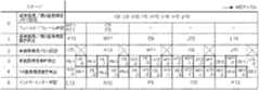
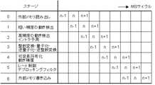
一方、ハードウェアの動画像符号化装置では、回路の稼働率を上げるためにMB単位のパイプライン(本特許請求の範囲および明細書では、マクロブロックパイプラインまたはMBパイプラインという。)が採用されるのが一般的である(例えば、非特許文献1のpp.126-128、図3参照)。また、ハードウェアの動画像符号化装置では、通常横方向のMBの並び(以下MB行という)内では左端MBから右端MBに向かって符号化される。そして、1つのMB行に含まれる右端のMBの符号化が終了すると、次にその下のMB行に属するMBが左端MBから右端MBに向かって符号化される。これがピクチャの最も上のMB行からピクチャの最も下のMB行まで繰り返される。図48は、従来のH.264の符号化器のMBパイプラインにおいて、MBがMBパイプラインの各ステージを流れていく様子を示したものである。n−1、n、およびn+1はあるMB行中の左からそれぞれn−1番目、n番目、n+1番目のMBを表す。また、MBサイクルとは、MBパイプラインの各ステージで1個のMBが処理されるために要する時間の単位をいい、各ステージでは1MBサイクルで1個のMBが処理される。 On the other hand, a hardware moving image encoding apparatus employs a pipeline in MB units (referred to as a macroblock pipeline or an MB pipeline in the claims and the specification) in order to increase the operation rate of a circuit. (For example, see Non-Patent
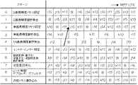
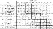
図48では、ステージ0で1MBサイクルかけて外部メモリから1個のMBの符号化に必要なデータを読み出す。ステージ1で1MBサイクルかけて1個のMBについて粗い精度の動き検出を行う。ステージ2で1MBサイクルかけてステージ1で検出された粗い精度の候補動きベクトルの周囲の狭い範囲で詳細な動き検出を行うと共に、イントラ予測を行う。ステージ3では1MBサイクルかけて1個のMBについて整数変換、量子化、逆量子化、および逆整数変換を行う。ステージ4では1MBサイクルかけて1個のMBについて可変長符号化と動き補償を行う。そして、ステージ5で1MBサイクルかけて1個のMBについてレート制御とデブロッキングフィルタを行い、ステージ6で1MBサイクルかけて1個のMB分の再生画素やビットストリームを外部メモリに書き込む。MBサイクルを1000サイクルと仮定すると、MBパイプラインを行わない場合には1個のMBの符号化処理に7000サイクルかかるのに対し、図48のMBパイプラインでは1000サイクルごとに1つのMBの符号化が終了する。 In FIG. 48, data necessary for encoding one MB is read out from the external memory over 1 MB cycle in
しかし、このMBパイプラインで左隣接MBの処理結果に応じた適応処理を行うためには、以下の4点の課題がある。 However, in order to perform adaptive processing according to the processing result of the left adjacent MB in this MB pipeline, there are the following four problems.
(1)図48に示すように、n−1番目のMBについてレート制御が終了したとき、既にn+1番目のMBまで量子化が終了している。従って、n−1番目のMBの発生符号量に応じて量子化パラメータを変更できるのは、n+2番目以降のMBである。すなわち、2MB分レート制御が遅れる。(1) As shown in FIG. 48, when the rate control is finished for the (n-1) th MB, the quantization has already been finished up to the (n + 1) th MB. Therefore, the quantization parameter can be changed according to the generated code amount of the (n−1) th MB for the (n + 2) th and subsequent MBs. That is, 2 MB rate control is delayed.
(2)図48では動き検出をMBパイプライン2段で実行し、ステージ2で高精度の動きベクトル検出と同時にイントラ予測を実行している。高精度の動きベクトルが決定し、かつイントラ予測かインター予測かが決まらなければ正確なPMVは算出できないが、n−1番目のMBについて高精度の動きベクトルとイントラ予測かインター予測かが決まったときにはn番目のMBについてステージ1における粗い精度の動きベクトル検出は終了している。このため、図48のMBパイプラインでは、左隣接MBについては荒い精度の動きベクトル検出結果しか考慮して動きベクトルを選択することはできず、左隣接MBにおける高精度の動きベクトルおよびイントラ予測/インター予測判定結果を考慮して動きベクトルを選択することができない。加えて、H.264ではMBを分割した8画素×16画素、8画素×8画素、4画素×4画素等のSBでも動きベクトルの符号量を考慮して動きベクトル検出を行うことが望ましいが、図48のMBパイプラインでは左隣接SB、上隣接SB、および右上隣接SBの動きベクトルの符号量を考慮して動きベクトル検出を行うことは困難である。(2) In FIG. 48, motion detection is executed in two stages of the MB pipeline, and intra prediction is executed simultaneously with high-precision motion vector detection in
(3)16画素×16画素ブロックイントラ予測モードは、左隣接16画素×16画素ブロックと上隣接16画素×16画素ブロックの画素値と現ブロックの画素値を評価して決定される。ここで、評価に使用する隣接16画素×16画素ブロックの画素は再生画素であることが望ましい。再生画素は、イントラ予測やインター予測で得られた予測誤差を整数変換、量子化、逆量子化および逆整数変換し、予測値を加算することにより求められる。しかし、図48のMBパイプラインではステージ3でn−1番目のMBの整数変換等が終わり、ステージ4の動き補償でn−1番目のMBの再生画素が作成されたときには、ステージ2におけるn番目のMBのイントラ予測は終了している。このため、n番目のMBについて16画素×16画素ブロックイントラ予測の予測モード判定を行うときには、その左に隣接したn−1番目のMBの再生画素を使用することはできない。このため、左に隣接したn−1番目の16画素×16画素ブロックの予測モード判定については再生画素ではなく、符号化中の現ピクチャの画素を使用せざるを得ない。同様に、H.264における4画素×4画素ブロックイントラ予測モードでは左隣接、上隣接、右上隣接の4画素×4画素ブロックの再生画素を使用して予測モードを決定することが望ましいが、図48のMBパイプラインでは不可能であり、次善の手段として符号化中の現ピクチャの画素を使用せざるを得ない。このため、図48のMBパイプラインにより決定されるイントラ予測モードは準最適なものとなる。(3) The 16 pixel × 16 pixel block intra prediction mode is determined by evaluating the pixel value of the left adjacent 16 pixel × 16 pixel block and the upper adjacent 16 pixel × 16 pixel block and the pixel value of the current block. Here, it is desirable that the pixels of the adjacent 16 pixel × 16 pixel block used for evaluation are reproduction pixels. The reproduced pixel is obtained by performing integer conversion, quantization, inverse quantization, and inverse integer conversion on a prediction error obtained by intra prediction or inter prediction, and adding a prediction value. However, in the MB pipeline of FIG. 48, when the integer conversion of the (n−1) th MB is completed in
(4)イントラ予測値は、符号化装置と復号装置で同一のものを使用しなければならないため、再生画素から作成せざるを得ない。一方、PピクチャとBピクチャでは、左に隣接したn−1番目のMBがインター予測モードと判定された場合には、動き補償が終わるまで再生画素が得られない。しかし、図48のMBパイプラインでは、n−1番目のMBについてのステージ4における再生画素の生成と、n番目のMBについてのステージ3における整数変換等は同時に実行される。このため、PピクチャとBピクチャでは、n−1番目のMBの再生画素を用いて予測値を作成し、n番目のMBの整数変換等を行うことは困難である。(4) Since the same intra prediction value must be used in the encoding device and the decoding device, it must be generated from the reproduced pixels. On the other hand, in the P picture and the B picture, when the n−1th MB adjacent to the left is determined to be in the inter prediction mode, a reproduced pixel cannot be obtained until the motion compensation is completed. However, in the MB pipeline of FIG. 48, the generation of the reproduction pixel in the
また、ピクチャのデータ量は膨大であるため、一般にピクチャは動画像符号化装置の外部のメモリに記憶される。図49は、従来の動画像符号化装置の構成を示すブロック図である(例えば、非特許文献2のp2009、図3参照)。動きベクトル検出器106は、内部メモリ104と動き検出回路105で構成される。従来の動きベクトル検出器106では動きベクトルが存在する可能性がある領域(以下、参照領域という。)を動きベクトル検出器106の外部メモリ4から動きベクトル検出器106の内部メモリ104にコピーし、内部メモリ104内の画素に対して動きベクトルを検出するための演算が行われる。図50は、隣接する2つのMB107、108の参照領域109、110の例を示す。MB108の参照領域110はMB107の参照領域109と大部分重なっており、重なっていない領域の幅はMBの横方向の画素数と一致する。参照領域110は参照領域109より右方向にMBの横方向の画素数分ずれているだけである。以下では、このずれている領域を更新領域111と呼ぶ。従来の動きベクトル検出器106はこの性質を利用して外部メモリ4と動きベクトル検出器106の内部メモリ104間の画素転送量を削減する。外部メモリ4から内部メモリ104へは更新領域111のみ転送し、MB108の動き検出を開始するとき、参照領域の原点を参照領域109の(0,0)から参照領域110の(0,0)’に付け替える。このように、更新領域111のみ読み込んで参照領域を更新することにより外部メモリ4から内部メモリ104への転送量を削減していた。すなわち、従来は参照領域の横方向の重なりを利用して外部メモリ4と内部メモリ104の間の画素転送量を削減していた。これにより、従来の1チップMPEG−2コーデックLSIは、200MHzで動作する32ビット幅のDDR−SDRAMを2個外付けすることで1080iの動画像を符号化することが可能となった(例えば、非特許文献3のpp.12-13参照)。Also, since the amount of picture data is enormous, the picture is generally stored in a memory external to the moving picture coding apparatus. FIG. 49 is a block diagram showing a configuration of a conventionalmoving image encoding device (see, for example, p2009 of
しかし、DCI(Digital Cinema Initiative)の定めたデジタルシネマ規格による1ピクチャの大きさは4096画素×2160画素であり、1080i(1920画素×1080画素)の4倍の画素数を有する。また、1080iの3倍を超える画素数のピクチャを1080iの2倍のレート(60枚/秒)で出力するCMOSセンサが開発されている(例えば、非特許文献4のsesion 27.1参照)。最新の技術を用いれば、デジタルシネマクラスの動画像を出力するビデオカメラも実現できると予測されるところ、従来の技術を用いたのでは動画像符号化LSIに256ビット幅の入力端子を設けるか、または外部メモリを800MHz程度の速度で動作させることが必要となるという問題がある。However, the size of one picture according to the digital cinema standard defined by DCI (Digital Cinema Initiative) is 4096 pixels × 2160 pixels, which is four times as many as 1080i (1920 pixels × 1080 pixels). In addition, a CMOS sensor has been developed that outputs a picture having a number of pixels exceeding three times that of 1080i at a rate twice that of 1080i (60 pictures / second) (for example, see section 27.1 of Non-Patent Document4 ). If the latest technology is used, it is predicted that a video camera that outputs a moving image of a digital cinema class can be realized. If the conventional technology is used, is a moving image encoding LSI provided with a 256-bit width input terminal? There is a problem that it is necessary to operate the external memory at a speed of about 800 MHz.
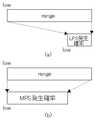
また、動画像符号化装置の処理速度が遅く、1台では処理が間に合わない場合、複数の動画像符号化装置による並列処理が行われる。この場合のピクチャ分割方法として、図51に示す4種類が考えられる(例えば、非特許文献5のp.17、Figure
1参照)。すなわち、(a)横分割、(b)縦分割、(c)縦横分割、(d)スライスインタリーブである。従来は、複数の画像符号化装置間の接続やデータ転送が簡単になるという理由で(a)横分割が採用されることが多かった(例えば、非特許文献3参照)。しかし、横分割し、複数の動画像符号化装置で並列処理する方法では、カメラから1ピクチャ分の画素が全て読み込まれるまで符号化開始が遅延するという問題がある。この遅延が生じることは、テレビ電話や遠隔監視等の低遅延を要求される通信アプリケーションでは望ましくない。In addition, when the processing speed of the moving image encoding device is slow and the processing cannot be performed in time with one unit, parallel processing by a plurality of moving image encoding devices is performed. As the picture dividing method in this case, four types shown in FIG. 51 can be considered (for example, p.17 of
1). That is, (a) horizontal division, (b) vertical division, (c) vertical and horizontal division, and (d) slice interleaving. Conventionally, (a) horizontal division has been often employed because connection and data transfer between a plurality of image encoding devices are simplified (see, for example, Non-Patent Document3 ). However, the method of performing horizontal division and performing parallel processing with a plurality of moving image encoding apparatuses has a problem that the start of encoding is delayed until all pixels for one picture are read from the camera. The occurrence of this delay is undesirable in communication applications that require low delay such as videophones and remote monitoring.
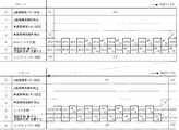
また、H.264では可変長符号化を算術符号化の一種であるCABACで行うことができる。図52は、CABAC符号化器のブロック図を示す。CABACでは、まず、多値のシンタックスデータ(H.264ではシンタックスエレメントと呼ばれるが、本明細書と特許請求の範囲では、シンタックスデータという。)を2値化回路112により可変長の2値化シンボルに変換する。次に、コンテクスト計算回路113により2値化シンボル1
ビット(以下、symbolという。)ごとにコンテキスト計算を行う。そして、計算されたコンテキスト情報に応じて、算術符号化の確率テーブル115を選択し、算術符号化回路114によりsymbolを算術符号化するとともに、確率テーブル115の更新を行い、次のsymbolの算術符号化には更新された確率テーブル115を用いる。H. In H.264, variable length coding can be performed by CABAC, which is a kind of arithmetic coding. FIG. 52 shows a block diagram of a CABAC encoder. In CABAC, first, multi-value syntax data (referred to as syntax data in H.264 but referred to as syntax data in the present specification and claims) is converted to
Context calculation is performed for each bit (hereinafter referred to as symbol). Then, the arithmetic coding probability table 115 is selected according to the calculated context information, the symbol is arithmetically coded by the
図53は、算術符号化回路114の処理内容を表すBiari_encode_symbol処理フローである(例えば、非特許文献6参照)。CABACでは、符号化の状態をsymbol系列の存在区間の幅(以下、rangeという。)と下端(以下、lowという)で表す。rangeとlowのビット幅はそれぞれ9ビットと10ビットであり、スライスの先頭でrangeは0x1FE(0xは、16進数であることを示す。以下、同じ)、lowは0x000に初期化される。0と1のうち、発生確率の低い方がLPS(Least Probable Symbol)に割り当てられ、発生確率の高い方がMPS(Most Probable Symbol)に割り当てられる。確率テーブル115は、コンテクスト情報ごとにsymbolの発生確率を保持している。各発生確率は0または1のいずれがMPSに割り当てられているかという情報とLPSの発生確率(以下、rLPSという。)の状態を示す番号(以下、stateという。)で示され、rLPSは、stateとrangeによってテーブル(rLPS_table_64x4)を引くことにより求められる(ステップS30)。一方、MPSの発生確率は、rangeからrLPSを減算することで算出される(ステップS31)。FIG. 53 is a Biari_encode_symbol processing flow showing the processing contents of the arithmetic encoding circuit 114 (see, for example, Non-Patent Document6 ). In CABAC, the coding state is represented by the width (hereinafter referred to as “range”) and the lower end (hereinafter referred to as “low”) of the existence sequence of the symbol sequence. The bit widths of range and low are 9 bits and 10 bits, respectively, and at the head of the slice, range is initialized to 0x1FE (0x indicates a hexadecimal number, hereinafter the same), and low is initialized to 0x000. Of 0 and 1, the lower occurrence probability is assigned to LPS (Least Probable Symbol), and the higher occurrence probability is assigned to MPS (Most Probable Symbol). The probability table 115 holds the occurrence probability of symbol for each context information. Each occurrence probability is indicated by information indicating whether 0 or 1 is assigned to the MPS and a number (hereinafter referred to as “state”) indicating an LPS occurrence probability (hereinafter referred to as “rLPS”). And range are used to obtain a table (rLPS_table_64x4) (step S30). On the other hand, the occurrence probability of MPS is calculated by subtracting rLPS from range (step S31).
symbolがLPSであるときのrangeとlowの変化を図54(a)に示す。symbolがLPSであるとき、MPSの発生確率を加算することによってlowが更新され、rangeにはrLPSが設定される(ステップS33)。state=0であれば、次の符号化状態における0と1の発生確率の大小が逆転すると予想されるため、MPSに対応する0と1が入れ替えられる(ステップS34、S35)。そして、LPSに対応する遷移テーブル(AC_next_state_LPS_64)を引くことによって、stateの状態が更新される(ステップS36)。 FIG. 54A shows changes in range and low when symbol is LPS. When symbol is LPS, low is updated by adding the occurrence probability of MPS, and rLPS is set in range (step S33). If state = 0, the occurrence probability of 0 and 1 in the next coding state is expected to be reversed, so 0 and 1 corresponding to MPS are switched (steps S34 and S35). Then, the state of the state is updated by drawing the transition table (AC_next_state_LPS_64) corresponding to the LPS (step S36).
symbolがMPSであるときのrangeとlowの変化を図54(b)に示す。symbolがMPSであるとき、lowは変化せず、rangeにはMPSの発生確率が設定される(ステップS31)。そして、MPSに対応する遷移テーブル(AC_next_state_MPS_64)を引くことによって、stateの状態が更新される(ステップS37)。 FIG. 54B shows changes in range and low when symbol is MPS. When symbol is MPS, low does not change, and MPS occurrence probability is set in range (step S31). Then, the state of the state is updated by drawing the transition table (AC_next_state_MPS_64) corresponding to the MPS (step S37).
range<0x100のときには、再正規化が行われ、rangeとlowが拡大される(ステップS38)。再正規化により、rangeの範囲は、0x100≦range≦0x1FEとなる。 When range <0x100, renormalization is performed, and range and low are expanded (step S38). Due to renormalization, the range of range becomes 0x100 ≦ range ≦ 0x1FE.
このように、symbolごとに算術符号化せざるを得えず、処理サイクル数がかかるにもかかわらず、1つのスライス内では1個の確率テーブル115しか使用できない。このため、算術符号化器114は原理的に並列化できない。 In this way, arithmetic coding must be performed for each symbol, and only one probability table 115 can be used in one slice despite the number of processing cycles. For this reason, the
更に、IピクチャにはPピクチャやBピクチャに比べて多くの符号量が配分される。このため、ピクチャ全体の2値化シンボルの平均発生量に比べてIピクチャの2値化シンボルの発生量は多い。その上、急激に発生符号量が増加したとき、レート制御が破綻することを防ぐためにMBごとの発生符号量を早期にレート制御に反映させる必要がある。このように、算術符号化回路114には、処理サイクル数がかかるにもかかわらず、並列化が不可能で、しかも発生符号量の多いIピクチャにおいて突発的に発生する2値化シンボル発生量を処理できるだけの性能が必要となるという問題がある。 Furthermore, a larger amount of code is allocated to the I picture than to the P picture and the B picture. For this reason, the amount of occurrence of binarized symbols in the I picture is larger than the average amount of binarized symbols in the entire picture. In addition, when the generated code amount suddenly increases, the generated code amount for each MB needs to be reflected in the rate control at an early stage in order to prevent the rate control from failing. In this way, the
なお、CABACに関して実際の算術符号化は行わずに2値化シンボルのシンボル長の総和から算術符号化の発生符号量を推定する方法が提案されている(例えば、非特許文献7のp.20、図6参照)。具体的には、2値化シンボル長N
と直前の符号化済みピクチャの2値化シンボル長と発生符号量との比率αを用いて、発生符号量R=α×Nと推定するものである。ルックアップテーブルを用いれば多値のシンタックスデータを2値化シンボルに1CKで変換することが可能であるため、この方法を用いれば算術符号化の発生符号量の推定をシンタックスデータ当たり1CKで行うことができる。
The generated code amount R = α × N is estimated using the ratio α between the binary symbol length of the immediately previous encoded picture and the generated code amount. Since it is possible to convert multi-level syntax data into binarized symbols with 1 CK using a lookup table, this method can be used to estimate the amount of code generated by arithmetic coding at 1 CK per syntax data. It can be carried out.
算術符号化回路が突発的に増加する2値化シンボル発生量を処理できるだけの性能を有していなくても算術符号化可能とする。Arithmetic coding circuitenables arithmetic coding not have a performance sufficient to handle the binary symbol generation amount increases suddenly.
本発明の動画像符号化装置は、ピクチャの左端から右端まで横方向に連続して並んだマクロブロックの集まりであるマクロブロック行の中では、左端のマクロブロックから符号化を開始し、右に隣接したマクロブロックを順番に符号化する動画像符号化部であって、
動画像符号化の処理が少なくとも2つの処理に分割され、当該分割された処理を行うステージが少なくとも2ステージ含まれ、当該ステージの中にシンタックスエレメントを可逆圧縮して圧縮されたシンタックスエレメントを生成する可変長符号化ステージが含まれるマクロブロックパイプラインを含み、
縦方向に連続する少なくとも2行であって、ピクチャ全体に含まれる前記マクロブロック行の総行数よりも少ない行数の前記マクロブロック行をひとまとまりとして選択し、
前記ひとまとまりのマクロブロック行の中の最も上のマクロブロック行に含まれるマクロブロックを前記マクロブロックパイプラインに投入し、
前記ひとまとまりのマクロブロック行の中の上から2行目のマクロブロック行に含まれるマクロブロックから最も下のマクロブロック行に含まれるマクロブロックまで順番に、各マクロブロック行の上に隣接したマクロブロック行に含まれる直前投入マクロブロックが前記マクロブロックパイプラインに投入された後に、当該各マクロブロック行に含まれ、当該直前投入マクロブロックより左に位置し、かつ当該直前投入マクロブロックが右上隣接マクロブロックではないマクロブロックを、前記マクロブロックパイプラインに投入する
動画像符号化部と、
前記可変長符号化ステージにおいて前記圧縮されたシンタックスエレメントが書き込まれる圧縮シンタックスエレメント記憶部と、
前記ひとまとまりのマクロブロック行の中の最も上のマクロブロック行について左端のマクロブロックから右端のマクロブロックまで順番に前記圧縮シンタックスエレメント記憶部から前記圧縮されたシンタックスエレメントが読み出され、前記ひとまとまりのマクロブロック行の中の上から2行目のマクロブロック行から最も下のマクロブロック行まで順次、各マクロブロック行について左端のマクロブロックから右端のマクロブロックまで順番に前記圧縮シンタックスエレメント記憶部から前記圧縮されたシンタックスエレメントが読み出され、当該読み出された圧縮されたシンタックスエレメントから前記シンタックスエレメントを復元するシンタックスエレメント復元部と、
前記復元されたシンタックスエレメントを2値化シンボルに変換する2値化部と、
前記変換された2値化シンボルを算術符号化する算術符号化部と
を有する。The moving image encoding apparatus of the present invention starts encoding from the leftmost macroblock in the macroblock row that is a collection of macroblocks arranged in the horizontal direction from the left end to the right end of the picture, A video encoding unit that sequentially encodes adjacent macroblocks;
The video encoding process is divided into at least two processes, and at least two stages for performing the divided processes are included, and a syntax elementcompressed by lossless compression of the syntax element is included in the stage. Including a macroblock pipeline that includesa variable length encoding stage togenerate ,
Selecting the macroblock rows as a group with at least two rows that are continuous in the vertical direction and having a number of rows smaller than the total number of the macroblock rows included in the entire picture;
Injecting the macroblock included in the top macroblock row in the group of macroblock rows into the macroblock pipeline;
Macros adjacent on each macroblock row in order from the macroblock included in the second macroblock row from the top to the macroblock included in the bottommost macroblock row in the group of macroblock rows. After the previous input macroblock included in the block row is input to the macroblock pipeline, it is included in each macroblock row and is located to the left of the previous input macroblock, and the previous input macroblock is adjacent to the upper right. A video encoding unit that inputs macroblocks that are not macroblocks into the macroblock pipeline;
A compressed syntax element storage unit in which the compressed syntax element is written in the variable length encoding stage;
The compressed syntax elements are read from the compressed syntax element storage unit in order from the leftmost macroblock to the rightmost macroblock for the uppermost macroblock row in the group of macroblock rows, The compression syntax elements in a group of macroblock rows from the top to the bottom macroblock row from the top to the bottom macroblock row, in order from the leftmost macroblock to the rightmost macroblock for each macroblock row A syntax element restoration unit that reads the compressed syntax element from the storage unit and restores the syntax element from the read compressed syntax element;
A binarization unit that converts the restored syntax element into a binarized symbol;
An arithmetic encoding unit that arithmetically encodes the converted binary symbol .
好ましくは、本発明の動画像符号化装置は、前記動画像符号化の処理が、動画像符号化規格H.264に準拠しており、
前記可変長符号化ステージが、前記シンタックスエレメントをCAVLCで圧縮する。Preferably , in the moving image encoding apparatusof the present invention, the moving image encodingprocess is performed according to the moving image encoding standard H.264. H.264,
The variable length encoding stage compresses the syntax element with CAVLC.
好ましくは、本発明の動画像符号化装置は、ピクチャの最も上の前記ひとまとまりのマクロブロック行から符号化を開始し、下に隣接した前記ひとまとまりのマクロブロック行を順番に符号化する。Preferably, the moving picture coding apparatus according to the present inventionstarts coding from the uppermost group of macroblock rows of apicture, and sequentially encodes the lowermost group of macroblock rows adjacent to each other.
好ましくは、本発明の動画像符号化装置は、前記動画像符号化部を少なくとも2つ有する。Preferably, the moving image encoding device of the present invention includesat least two moving image encoding units.
また、本発明の動画像符号化装置は、ピクチャの左端から右端まで横方向に連続して並んだマクロブロックの集まりであるマクロブロック行を縦方向に隣接する2行ずつ組みにしてマクロブロック行の組を作成し、当該マクロブロック行の組に属する縦方向に隣接した2個のマクロブロックを組み合わせてマクロブロックペアを作成し、マクロブロックペアごとにフレーム符号化とフィールド符号化を選択して符号化を行い、前記マクロブロック行の組の中では、左端のマクロブロックペアから符号化を開始し、右に隣接したマクロブロックペアを順番に符号化する動画像符号化部であって、
動画像符号化の処理が4以上の処理に分割され、当該分割された処理を行うステージが4ステージ以上含まれ、当該ステージの中にシンタックスエレメントを可逆圧縮して圧縮されたシンタックスエレメントを生成する可変長符号化ステージが含まれるマクロブロックパイプラインを含み、
縦方向に連続する2組以上の前記マクロブロック行の組であって、ピクチャ全体に含まれる前記マクロブロック行の組の総数よりも少ない数の前記マクロブロック行の組をひとまとまりとして選択し、
前記ひとまとまりのマクロブロック行の組の中の最も上に位置するマクロブロック行の組に属するマクロブロックペアをフレーム符号化とフィールド符号化のいずれで符号化するか選択し、フレーム符号化を選択したときは当該マクロブロックペアに含まれる上フレームマクロブロックを前記マクロブロックパイプラインに投入し、フィールド符号化を選択したときは当該マクロブロックペアに含まれる片方のマクロブロックを前記マクロブロックパイプラインに投入し、
前記ひとまとまりのマクロブロック行の組の中の上から2番目のマクロブロック行の組から最も下に位置するマクロブロック行の組まで順番に、各マクロブロック行の組の上に隣接したマクロブロック行の組に属するマクロブロックペアに含まれる直前投入マクロブロックが前記マクロブロックパイプラインに投入された後に、当該各マクロブロック行の組に属し、当該直前投入マクロブロックを含むマクロブロックペアより左に位置し、かつ当該直前投入マクロブロックを含むマクロブロックペアが右上隣接マクロブロックペアではないマクロブロックペアをフレーム符号化とフィールド符号化のいずれで符号化するか選択し、フレーム符号化を選択したときは当該マクロブロックペアに含まれる上フレームマクロブロックを前記マクロブロックパイプラインに投入し、フィールド符号化を選択したときは当該マクロブロックペアに含まれる片方のマクロブロックを前記マクロブロックパイプラインに投入し、
前記ひとまとまりのマクロブロック行の組の中の最も下に位置するマクロブロック行の組に属するマクロブロックペアに含まれるマクロブロックが前記マクロブロックパイプラインに投入された後に、前記ひとまとまりのマクロブロック行の組みの中の最も上に位置するマクロブロック行の組から最も下に位置するマクロブロック行の組まで順番に、各マクロブロック行の組に属し、片方のマクロブロックのみ前記マクロブロックパイプラインに投入済みである前記マクロブロックペアに含まれる、まだ前記マクロブロックパイプラインに投入されていない他の片方のマクロブロックを前記マクロブロックパイプラインに投入する
動画像符号化部と、
前記可変長符号化ステージにおいて前記圧縮されたシンタックスエレメントが書き込まれる圧縮シンタックスエレメント記憶部と、
前記ひとまとまりのマクロブロック行の組の中の最も上のマクロブロック行の組について左端のマクロブロックペアから右端のマクロブロックペアまで順番に前記圧縮シンタックスエレメント記憶部から前記圧縮されたシンタックスエレメントが読み出され、前記ひとまとまりのマクロブロック行の組の中の上から2番目のマクロブロック行の組から最も下に位置するマクロブロック行の組まで順次、各マクロブロック行の組について左端のマクロブロックペアから右端のマクロブロックペアまで順番に前記圧縮シンタックスエレメント記憶部から前記圧縮されたシンタックスエレメントが読み出され、当該読み出された圧縮されたシンタックスエレメントから前記シンタックスエレメントを復元するシンタックスエレメント復元部と、
前記復元されたシンタックスエレメントを2値化シンボルに変換する2値化部と、
前記変換された2値化シンボルを算術符号化する算術符号化部と
を有する。The moving picture coding apparatus according to the present invention also includes a macroblock row in which macroblock rows, which are a set of macroblocks arranged in a row in the horizontal direction from the left end to the right end of a picture, are grouped into two adjacent rows in the vertical direction. A pair of macroblocks that are adjacent to each other in the macroblock row group and create a macroblock pair, and select frame coding and field coding for each macroblock pair. In the set of macroblock rows, encoding is started from the leftmost macroblock pair, and a moving picture encoding unit that sequentially encodes adjacent macroblock pairs on the right,
The video encoding process is divided into four or more processes, and four or more stages for performing the divided processes are included, and the syntax elementcompressed by reversibly compressing the syntax element is included in the stage.Including a macroblock pipeline that includes a variable length encoding stage to generate,
A set of two or more sets of macroblock rows that are consecutive in the vertical direction, and a set of macroblock rows that is smaller than the total number of sets of macroblock rows included in the entire picture is selected as a group;
Select whether to encode the macroblock pair belonging to the topmost macroblock row set in the group of macroblock rows by frame encoding or field encoding, and select frame encoding When the frame encoding is selected, the upper frame macroblock included in the macroblock pair is input to the macroblock pipeline. When field coding is selected, one macroblock included in the macroblock pair is input to the macroblock pipeline. Throw in,
Macroblocks adjacent to each set of macroblock rows in order from the second set of macroblock rows from the top to the bottom set of macroblock rows in the set of macroblock rows After a previous input macroblock included in a macroblock pair belonging to a set of rows is input to the macroblock pipeline, the macroblock pair belonging to the set of each macroblock row and to the left of the macroblock pair including the previous input macroblock When a macro block pair that is located and the macro block pair including the immediately preceding input macro block is not the upper right adjacent macro block pair is to be encoded by frame encoding or field encoding, and frame encoding is selected Indicates the upper frame macroblock included in the macroblock pair as the macroblock. Tsu put into click pipeline, when you select the field coding charged with macroblocks of one included in the macroblock pair in the macroblock pipeline,
After a macroblock included in a macroblock pair belonging to the lowest set of macroblock rows in the set of macroblock rows is input to the macroblock pipeline, the set of macroblocks The macroblock pipeline belongs to each macroblock row set in order from the topmost macroblock row set to the bottommost macroblock row set in the row set, and only one macroblock belongs to the macroblock pipeline. A video encoding unit that inputs the other macroblock included in the macroblock pair that has already been input to the macroblock pipeline and that has not yet been input to the macroblock pipeline;
A compressed syntax element storage unit in which the compressed syntax element is written in the variable length encoding stage;
The compressed syntax element from the compressed syntax element storage unit in order from the leftmost macroblock pair to the rightmost macroblock pair for the uppermost macroblock row set in the set of macroblock rows. Are sequentially read from the second set of macroblock rows to the lowest set of macroblock rows in the set of macroblock rows, and the leftmost for each set of macroblock rows. The compressed syntax element is read from the compressed syntax element storage unit in order from the macro block pair to the rightmost macro block pair, and the syntax element is restored from the compressed syntax element that has been read. A syntax element restoration unit to perform,
A binarization unit that converts the restored syntax element into a binarized symbol;
An arithmetic encoding unit that arithmetically encodes the converted binary symbol .
好ましくは、本発明の動画像符号化装置は、前記動画像符号化の処理が、動画像符号化規格H.264に準拠しており、
前記可変長符号化ステージが、前記シンタックスエレメントをCAVLCで圧縮する。Preferably , in the moving image encoding apparatusof the present invention, the moving image encodingprocess is performed according to the moving image encoding standard H.264. H.264,
The variable length encoding stage compresses the syntax element with CAVLC.
好ましくは、本発明の動画像符号化装置は、ピクチャの最も上の前記ひとまとまりのマクロブロック行の組から符号化を開始し、下に隣接した前記ひとまとまりのマクロブロック行の組を順番に符号化する。Preferably, the moving picture coding apparatus according to the present inventionstarts coding from the set of macroblock rows at the top of apicture, and sequentially sets the set of macroblock rows adjacent below. Encode.
好ましくは、本発明の動画像符号化装置は、前記動画像符号化部を少なくとも2つ有する。Preferably, the moving image encoding device of the present invention includesat least two moving image encoding units.
本発明によれば、算術符号化部が突発的に増加する2値化シンボル発生量を処理できるだけの性能を有していなくても算術符号化することができる。特に、圧縮シンタックスエレメント記憶部にIピクチャの圧縮されたシンタックスエレメントとその前後のPピクチャやBピクチャの圧縮されたシンタックスエレメントを記憶できるだけの十分な記憶容量を持たせれば、算術符号化部の性能がIピクチャにおいて突発的に発生する2値化シンボル発生量を処理できる性能を下回っていても算術符号化することができる。
According to the present invention, arithmetic coding can be performed even if the arithmetic codingunit does not have a performance sufficient to process a binarized symbol generation amount that suddenly increases. In particular, if have sufficient storage capacity to thecompression syntax element storage unit and thecompressed syntax elements of I-pictures can be storedcompressed syntax elements before and after the P-picture and B-picture, the arithmetic codingpart performance can be arithmetic coding even below the suddenly can handle binary symbol generation amount for generating performance in I-picture.
また、あるMBの2値化シンボルの発生量が突発的に増加し、仮算術符号化した結果真の算術符号化回路の処理能力を超えると予測されるときにはそのMBを含むピクチャ全体をCAVLC符号化し、一方、仮算術符号化した結果真の算術符号化回路で処理できると予測されるときにはそのMBを含むピクチャ全体をCABAC符号化することができる。これにより、真の算術符号化回路の性能が不測するという状況を確実に回避できる。更に、CAVLC符号化回路でCAVLC符号化ビットストリームの符号量を算出し、CAVLC符号化と仮算術符号化の仮発生符号量を比較して、ピクチャごとに発生符号量が少ないと推測されるエントロピー符号化モードを選択することもできる。In addition , when the amount of binarized symbols generated in a certain MB suddenly increases and is predicted to exceed the processing capability of a true arithmetic encoding circuit as a result of provisional arithmetic encoding, the entire picture including the MB is encoded by the CAVLC code. On the other hand, when it is predicted that the result can be processed by a true arithmetic encoding circuit as a result of provisional arithmetic encoding, the entire picture including the MB can be CABAC encoded. As a result, a situation in which the performance of the true arithmetic coding circuit is unexpected can be surely avoided. Furthermore, the CAVLC encoding circuit calculates the code amount of the CAVLC encoded bitstream, compares the temporarily generated code amount of CAVLC encoding and provisional arithmetic encoding, and entropy that is estimated to be small for each picture. An encoding mode can also be selected.
本発明では、縦に連続する複数のMB行をひとまとまりとして、これらひとまとまりのMB行から、1つのMB行当たり1個のMBを選択し、これら選択された複数のMBを1個のMBパイプラインに連続して投入する。 In the present invention, a plurality of MB rows that are vertically continuous are grouped, one MB is selected per MB row from the group of MB rows, and the selected plurality of MBs are one MB. Put continuously into the pipeline.
以下、本発明の実施の形態に係る動画像符号化装置を図面に基づいて説明する。
Hereinafter, amoving picture coding apparatus according to an embodiment of the present invention will be described with reference to the drawings.
(第1の実施形態)
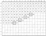
図1はMBパイプラインに連続して投入されるMBの例を示した説明図である。図1のピクチャはa行からl行までの12のMB行からなり、各MB行は0番目から15番目までの16個のMBで構成される。図1のピクチャでは、最初にa−MB行、b−MB行、c−MB行、d−MB行に含まれるMBが1個のMBパイプラインで符号化され、次にe−MB行、f−MB行、g−MB行、h−MB行に含まれるMBが1個のMBパイプラインで符号化され、最後にi−MB行、j−MB行、k−MB行、l−MB行に含まれるMBが1個のMBパイプラインで符号化される。図1中のe行10列、f行8列、g行6列、h行4列のMBは1個のMBパイプラインに連続して投入されるMBの一例である。f行8列のMBはe行10列のMBから左方向に1MB離れている。同様にg行6列のMBはf行8列のMBから左方向に1MB離れており、h行4列のMBはg行6列のMBから左方向に1MB離れている。これらの4つのMBは相互に左隣接、上隣接、または右上隣接のいずれの隣接関係にもない。以下では、複数のブロックが相互に左隣接、上隣接、または右上隣接のいずれの隣接関係にもないことを、これらのブロックは隣接関係にないという。(First embodiment)
FIG. 1 is an explanatory diagram showing an example of MBs continuously input into the MB pipeline. The picture in FIG. 1 is composed of 12 MB rows from a row to l row, and each MB row is composed of 16 MBs from 0th to 15th. In the picture of FIG. 1, first, MBs included in the a-MB row, b-MB row, c-MB row, and d-MB row are encoded by one MB pipeline, and then the e-MB row, MBs included in the f-MB line, the g-MB line, and the h-MB line are encoded by one MB pipeline, and finally the i-MB line, the j-MB line, the k-MB line, and the l-MB. MB included in a row is encoded by one MB pipeline. The MB of
図2は本発明が適用される動画像符号化装置のブロック図を示す。MB選択回路2は、図1に示すように、e−MB行、f−MB行、g−MB行、h−MB行をひとまとまりとし、e−MB行に属するMBについては、左下隣接MBがまだ選択されていないMBを選択し、かつ、f−MB行、g−MB行、およびh−MB行に属するMBについては、右上隣接MBが既に選択されているMBを選択することによって、e行10列、f行8列、g行6列、h行4列のMBを選択する。符号化データ設定回路3は、e行10列、f行8列、g行6列、h行4列のMBの順番で、各MBを符号化するために必要なデータをMBパイプライン1に設定する。MBを符号化するために必要なデータがMBパイプライン1に設定されると、そのMBはMBパイプライン1に投入される。h行4列のMBを符号化するために必要なデータがMBパイプライン1に設定され、h行4列のMBがMBパイプライン1に投入されると、MB選択回路2は、e行11列、f行9列、g行7列、h行5列のMBを新たに選択する。 FIG. 2 shows a block diagram of a moving picture coding apparatus to which the present invention is applied. As shown in FIG. 1, the
図3は本発明が適用される動画像符号化方法の処理のフローチャートを示す。e−MB行、f−MB行、g−MB行、h−MB行をひとまとまりとし、e−MB行に属するMBについては、左下隣接MBがまだ選択されていないMBを選択し、かつ、f−MB行、g−MB行、およびh−MB行に属するMBについては、右上隣接MBが既に選択されているMBを選択することによって、e行10列、f行8列、g行6列、h行4列のMBを選択する(ステップS1)。次に、e行10列、f行8列、g行6列、h行4列のMBの順番で、各MBを符号化するために必要なデータをMBパイプライン1に設定し、順次MBパイプラインに投入する(ステップS2、ステップS3)。MBを符号化するために必要なデータがMBパイプライン1に設定されると、そのMBはMBパイプライン1に投入される。h行4列のMBを符号化するために必要なデータがMBパイプライン1に設定され、h行4列のMBがMBパイプライン1に投入されると、ステップS1に戻り(ステップS4)、e行11列、f行9列、g行7列、h行5列のMBを新たに選択する(ステップS1)。 FIG. 3 shows a flowchart of the process of the moving picture encoding method to which the present invention is applied. e-MB line, f-MB line, g-MB line, and h-MB line are grouped, and for MBs belonging to the e-MB line, an MB for which the lower left neighboring MB is not yet selected is selected; and For MBs belonging to the f-MB row, the g-MB row, and the h-MB row, by selecting the MB for which the upper right adjacent MB has already been selected, the
これら4個のMBを1個のMBパイプライン1に連続して投入したときに、各MBがMBパイプライン1の各ステージを流れていく様子を図4に示す。ステージ0からステージ6の各処理内容は図45のものと同じである。また、図1のピクチャを構成する各MBがMBパイプライン1に投入され、ステージ0の処理が開始されるMBサイクル番号を図5に示す。図4に示すように、e行10列、f行8列、g行6列、h行4列の4個のMBは、MBサイクル番号がそれぞれ104、105、106、107のとき順番にステージ0に投入され、MBサイクル番号がそれぞれ110、111、112、113のとき順番にステージ6に達して符号化が終了する。このように、ひとまとまりの4つのMB行の中で、最も上のMB行に属するMB、上から2番目のMB行に属するMB、上から3番目のMB行に属するMB、上から4番目のMB行に属するMBの順番にMBパイプライン1に投入され、続いてそれらの右隣接MBが同様の順番でMBパイプライン1に投入される。 FIG. 4 shows a state in which each MB flows through each stage of the
本発明によれば、本実施形態のようにひとまとまりとして符号化するMB行の数が4のとき、左隣接MBの処理結果を3ステージ分フィードバックし、現MBの処理に反映できる。このため、図4中に矢印で示すように、例えば、f行7列のMBの高精度の動き検出結果とイントラ予測結果をf行8列のMBの粗い精度の動き検出に反映できる。このように、従来の技術と異なり、左に隣接したMBの高精度の動き検出結果とイントラ予測結果を考慮して現MBの動きベクトルを選択することができる。また、同様に矢印で示すように、f行7列のMBの動き補償の結果をf行8列のMBのイントラ予測に反映できる。従って、従来の技術と異なり、左に隣接したMBの動き補償により求められた再生画素を用いて現MBのイントラ予測を行うことができる。更に、f行7列のMBのレート制御結果をf行8列のMBの量子化に反映できる。このように、左に隣接したMBのレート制御結果に応じて現MBの量子化パラメータを修正することができる。According to the present invention, as human unity as in the presentembodiment when the number of MB rows to be encoded is 4, and three-stage partial feedback of the processing result of the left neighboring MB, it can be reflected in the processing of the current MB. For this reason, as indicated by an arrow in FIG. 4, for example, the high-precision motion detection result and the intra prediction result of the f-row 7-column MB can be reflected in the coarse-precision motion detection of the f-row 8-column MB. Thus, unlike the conventional technique, the motion vector of the current MB can be selected in consideration of the high-precision motion detection result and intra prediction result of the MB adjacent to the left. Similarly, as indicated by an arrow, the result of motion compensation of the MB of f rows and 7 columns can be reflected in the intra prediction of MBs of f rows and 8 columns. Therefore, unlike the conventional technique, intra prediction of the current MB can be performed using the reconstructed pixel obtained by motion compensation of the MB adjacent to the left. Further, the rate control result of the MB of f rows and 7 columns can be reflected in the quantization of MBs of f rows and 8 columns. In this way, the quantization parameter of the current MB can be corrected according to the rate control result of the MB adjacent to the left.
ここで、本実施形態では下に隣接したMB行に含まれるMBが上のMB行中のMBから左方向に1MB離れている場合を示したが、1MB以上離れていれば良く、例えば2MB離れていても本発明の目的を達成することができ、同様の作用・効果を生じる。また、縦に連続する4つのMB行をひとまとまりとして、これら4つのMB行から、1つのMB行当たり1個のMBを選択し、これら選択された4個のMBを1個のMBパイプラインに連続して投入する例を示したが、ひとまとまりのMB行の数は2以上であれば良く、例えば縦に連続する8つのMB行をひとまとまりとして、これら8つのMB行から、1つのMB行当たり1個のMBを選択し、これら選択された8個のMBを1個のMBパイプラインに連続して投入しても本発明の目的を達成することができ、同様の作用・効果を生じる。ただし、ひとまとまりのMB行の数が2のときは、左隣接MBの処理結果を1ステージ分しか現MBの処理にフィードバックできないため、図4のステージ構成では左隣接MBの動き補償とレート制御の結果をそれぞれ現MBのイントラ予測と整数変換・量子化・逆量子化・逆整数変換にフィードバックできない。ひとまとまりのMB行の数が2のときは、図4に示したものとステージ構成を変更する必要がある。Here, MB included in the MB row adjacent to the bottom in the presentembodiment showed a case in which distant1 MB to the left from the MB in MB line above, it is sufficient that apart at least1 MB, for example, The object of the present invention can be achieved even at a distance of2 MB, and the same actions and effects are produced. Also, taking four MB rows that are vertically continuous as one group, one MB per MB row is selected from these four MB rows, and these four MBs are selected as one MB pipeline. However, it is sufficient that the number of MB lines in a group is two or more. For example, eight MB lines that are vertically continuous are grouped, and one of these eight MB lines is used as one group. Even if one MB is selected per MB row, and the selected 8 MBs are continuously input to one MB pipeline, the object of the present invention can be achieved, and similar operations and effects can be achieved. Produce. However, when the number of MB rows in a group is 2, the processing result of the left adjacent MB can be fed back to the current MB processing for only one stage. Therefore, in the stage configuration of FIG. Cannot be fed back to the current MB intra prediction and integer transform / quantization / inverse quantization / inverse integer transform. When the number of MB lines in a group is 2, it is necessary to change the stage configuration from that shown in FIG.
(第2の実施形態)
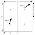
図6は8画素×8画素の4つのSB(以下、8×8SBという。)に分割されたMBを示す。本実施形態では、4つの8×8SBについて動きベクトルのコストと予測誤差のコストの和が最小となる動きベクトルを検出する例について示す。一般に、PMVと動きベクトルの距離が遠いほど動きベクトルのコストは高いと評価される。このため、各8×8SBについて動き検出を始める前に、その8×8SBのPMVが決まっていなければならない。そして、例えば、左隣接8×8SB、上隣接8×8SB、右上隣接8×8SBの動きベクトルに基づいてPMVを決めるとすると、図6中の0、1、2、3の番号を付された順番に8×8SBごとの動きベクトルを検出しなければならないことになる。ただし、3番の8×8SBの動きベクトル検出時に右上隣接8×8SBの動きベクトルは存在しないため、3番の8×8SBのPMVは1番と2番の8×8SBの動きベクトルMV1とMV2に基づいて決められる。(Second Embodiment)
FIG. 6 shows an MB divided into four SBs of 8 pixels × 8 pixels (hereinafter referred to as 8 × 8SB). In the presentembodiment , an example in which a motion vector that minimizes the sum of the cost of the motion vector and the cost of the prediction error is detected for four 8 × 8 SBs will be described. Generally, it is estimated that the cost of a motion vector is higher as the distance between the PMV and the motion vector is longer. Therefore, before starting motion detection for each 8 × 8 SB, the 8 × 8 SB PMV must be determined. For example, if PMV is determined based on the motion vector of the left adjacent 8 × 8SB, the upper adjacent 8 × 8SB, and the upper right adjacent 8 × 8SB, the
図7はMBパイプラインに連続して投入されるMBの例を示した説明図である。図7のピクチャはa行から始まっており、r行の下方にもMB行が存在する。また、16列以降にもMBが存在する。本実施形態ではi−MB行、j−MB行、k−MB行、l−MB行、m−MB行、n−MB行、o−MB行、p−MB行をひとまとまりとして、これらひとまとまりのMB行から、i行15列、j行13列、k行11列、l行9列、m行7列、n行5列、o行3列、p行1列のMBを選択し、これら選択された8つのMBを1個のMBパイプラインに連続して投入する例を示す。FIG. 7 is an explanatory diagram showing an example of MBs continuously input into the MB pipeline. The picture in FIG. 7 starts from the a line, and there is an MB line below the r line. There are also MBs after the 16th column. In thisembodiment , the i-MB line, j-MB line, k-MB line, l-MB line, m-MB line, n-MB line, o-MB line, and p-MB line are taken as a group. Select MB of i rows, 15 columns, j rows, 13 columns, k rows, 11 columns, l rows, 9 columns, m rows, 7 columns, n rows, 5 columns, o rows, 3 columns, and p rows, 1 column from a set of MB rows. An example is shown in which these eight selected MBs are continuously input into one MB pipeline.
図8は8×8SBごとの動きベクトルを検出するために、8つのMB行に含まれるMBを1個のMBパイプラインに連続して投入したとき、各MBが各ステージを流れていく様子を示す。図9は本発明が適用される動きベクトル検出回路12のブロック図を示す。外部メモリ4には単画素精度の画像が記憶されている。ステージ0で外部メモリ4から画像を読み出す。その画像を2画素精度画像作成回路5で縮小して2画素精度の画像を作成し、2画素精度メモリ6に書き込む。ステージ1で2画素精度メモリ6から画像を読み出しながら、2画素精度動き検出回路7により2画素精度の候補動きベクトルを検出する。そして、ステージ2で候補ベクトルの周辺の領域を外部メモリ4から読み出して、単画素精度メモリ8に書き込む。ここで、一般に外部の大容量メモリは低速であるため、外部メモリ4から単画素精度メモリ8に転送するために1ステージ割り当てている。単画素精度メモリ8から2画素精度候補ベクトルの周辺の領域を読み出しながら、ステージ3で単画素精度動き検出回路9により動きベクトルを検出する。その後、ステージ4で単画素精度メモリ8から単画素精度画素を読み出して、1/4画素精度画像作成回路10で1/4画素精度の画像を作成しながら1/4画素精度動きベクトル検出回路11を用いて1/4画素精度動きベクトル検出を行う。単画素精度メモリ8からは単画素精度動き検出回路9と1/4画素精度画像作成回路10に単画素精度画像を供給することになるため、単画素精度メモリ8はダブルバッファ構成や2リード以上可能な多ポートメモリとする必要がある。なお、図8ではステージ4で単画素精度動きベクトルの周囲を直接探索して1/4画素精度動きベクトルを検出するとしたが、ステージ4で半画素精度動きベクトルを検出した後、ステージ5で半画素精度動きベクトルの周囲を探索して1/4画素精度動きベクトルを検出しても良い。また、ステージ3で単画素精度動きベクトル検出と半画素精度動きベクトル検出を行い、ステージ4で1/4画素精度動きベクトル検出を行っても良い。FIG. 8 shows how each MB flows through each stage when MBs included in 8 MB rows are continuously input to one MB pipeline in order to detect a motion vector every 8 × 8 SB. Show. FIG. 9 shows a block diagram of a motion
ステージ1〜ステージ5ではMBサイクルを4つのSBサイクルに分割し、各SBサイクルで8×8SBごとの処理を行う。ここで、SBサイクルとは、1個のSBが処理されるために要する時間の単位をいい、SBごとの処理を行うとき、MBサイクルはSBサイクルに分割される。以下では、MBサイクルがSBサイクルに分割され、SBごとの処理を行うステージ群をSBパイプライン(またはサブブロックパイプライン)と呼ぶ。図8中のステージ1〜ステージ5がSBパイプラインである。図10はSBパイプラインの詳細な動作を示す。−0、−1、−2、−3はそれぞれ図6中の0、1、2、3の番号を付された8×8SBを意味する。例えば、i15−2はi行15列のMBに含まれる2番目の8×8SBを表す。図10では、ステージ5に空ステージを挿入し、例えばi15−0SBについてステージ4で検出された1/4画素精度動きベクトルをi15−1SBのステージ1における2画素精度動きベクトルのコスト計算に反映できるようにしている。このように、MBサイクルをSB数に等しい数のSBサイクルに分割したときは、(SB数+1)段のパイプラインとすることにより、同一のMB内における前の8×8SBの処理結果を次の8×8SBに反映させることができる。 In stages 1 to 5, the MB cycle is divided into four SB cycles, and each 8 × 8 SB process is performed in each SB cycle. Here, the SB cycle means a unit of time required for processing one SB, and when performing processing for each SB, the MB cycle is divided into SB cycles. Hereinafter, the stage group in which the MB cycle is divided into SB cycles and processing for each SB is performed is referred to as an SB pipeline (or sub-block pipeline).
なお、ステージ1〜ステージ5において8×8SBごとの動きベクトル検出回路と並列に動作するMBごとの動きベクトル検出回路を設けることが可能である。また、ステージ3〜5において、ステージ1において検出された8×8SBごとの候補ベクトルの周辺領域で8×8SBごとの動きベクトル検出と並列にMBごと、16画素×8画素SBごと、8画素×16画素SBごとの動きベクトルを検出することも可能である。 In
ステージ0〜5において動きベクトルが検出された後は、ステージ6で16×16イントラ予測モード、4×4イントラ予測モード、インター予測モード等の中から符号化効率の最も良くなる予測モードが選択される。ステージ7では整数変換、量子化、逆量子化、および逆整数変換が行われる。ステージ8では可変長符号化と動き補償が行われる。ステージ9ではレート制御とデブロッキングフィルタ処理が行われ、ステージ10では再生画素や符号化ビットストリームが外部メモリ4に書き込まれる。 After motion vectors are detected in
(第3の実施形態)
本実施形態では、1/4画素精度動き検出回路11を2個設け、ステージ3とステージ4を結合して、1個の8×8SBの1/4画素精度動き検出を2SBサイクルかけて行う例を示す。ステージ3とステージ4以外は、第2の実施形態のMBパイプラインと同一のステージ構成である。図11はSBパイプラインの詳細な動作を示し、図12はこの動作を実現するための動き検出回路13のブロック図を示す。2つの1/4画素精度動き検出回路11を1SBサイクルずらして動作させることにより、個々の8×8SBの1/4画素精度動き検出を2SBサイクルかけて行うことができる。(Third embodiment)
In thisembodiment, 1/4-pixel accuracy
(第4の実施形態)
本実施形態では、H.264における4画素×4画素イントラ予測(以下、4×4イントラ予測という。)に本発明を適用する例ついて説明する。図13は16個の4画素×4画素SB(以下、4×4SBという。)に分割されたMBを示す。4×4SBは図13中に付した0〜15の順番で符号化され、ビットストリームに変換される。例えば、3番の4×4SBについて4×4イントラ予測を行うときには、1番の4×4SBにおける下端4行の画素と2番の4×4SBの右端4列の画素が参照される。また、14番の4×4SBについて4×4イントラ予測を行うときには、12番と13番の4×4SBにおける下端の4行の画素と11番の4×4SBにおける右端4列の画素が参照される。これら隣接4×4SBに属する画素は再生画素を用いることが望ましい。(Fourth embodiment)
In thisembodiment, H. An example in which the present invention is applied to 4 pixel × 4 pixel intra prediction (hereinafter referred to as 4 × 4 intra prediction) in H.264 will be described. FIG. 13 shows an MB divided into 16 4 pixels × 4 pixels SB (hereinafter referred to as 4 × 4 SB). 4 × 4SB is encoded in the order of 0 to 15 in FIG. 13 and converted into a bit stream. For example, when 4 × 4 intra prediction is performed for the third 4 × 4SB, the pixels in the lowermost 4 rows of the first 4 × 4SB and the pixels in the fourth rightmost 4 columns of the second 4 × 4SB are referred to. In addition, when performing 4 × 4 intra prediction for the 14th 4 × 4SB, the pixels at the bottom four rows in the 12th and thirteenth 4 × 4SB and the pixels at the rightmost four columns in the 11th 4 × 4SB are referred to. The As the pixels belonging to these adjacent 4 × 4 SBs, it is desirable to use reproduction pixels.
図14は、4×4イントラ予測のために、8つのMB行に含まれるMBを1個のMBパイプラインに連続して投入したとき、各MBが各ステージを流れていく様子を示す。ステージ4で隣接4×4SBの再生画素を用いて4×4イントラ予測を行い、ステージ5で予測誤差に対して整数変換・量子化・逆整数変換・逆量子化を行ってイントラ予測値を加算し、再生画素を生成する。ステージ4の4×4イントラ予測回路とステージ5の整数変換・量子化・逆整数変換・逆量子化回路は、第2の実施形態または第3の実施形態で示したステージ1〜ステージ5の動き検出回路と並列に動作する。FIG. 14 shows a state where each MB flows through each stage when MBs included in eight MB rows are continuously input to one MB pipeline for 4 × 4 intra prediction.
本実施形態では、ステージ4と5においてMBサイクルを16のSBサイクルに分割する。このため、SBパイプラインのステージ数に比べてSBの数が多く、(SB数+1)段のSBパイプラインとすると、空ステージが増加し、効率が悪い。図15はSBパイプラインの詳細な動作を示す。−0、−1、−2、……、−15はそれぞれ図13中の0、1、2、……、15の番号を付された4×4SBを意味する。例えば、i15−8はi行15列のMBに含まれる8番目の4×4SBを表す。図15に示すように、本実施形態では、2つのMBに含まれる4×4SBを交互に処理することにより、1つのMBを2MBサイクル、すなわち32SBサイクルかけて処理する。1つのMBに属する4×4SBを4×4イントラ予測しているとき、同時に別のMBに属する4×4SBを整数変換・量子化・逆整数変換・逆量子化する。MBサイクルごとに1つのMBの処理を開始し、別のMBの処理を終えるように動作させ、MBパイプラインの他ステージと整合を取る。ただし、このように動作させると、図15に示すように、ステージ4の4×4イントラ予測において、2MBサイクルごとに1SBサイクル、すなわち1/16MBサイクルだけMBサイクルとずれが発生する。そのため、図15では、ステージ3の有効期間を15/16MBサイクルとし、ステージ4における1/16MBサイクルのずれを吸収している。なお、ステージ3の処理が重く、無効期間を設けることができないときは、ステージ6の有効期間を15/16MBサイクルとし、1/16MBサイクルのずれを吸収しても良い。このように動作させることにより、4×4イントラ予測回路と整数変換・量子化・逆整数変換・逆量子化を行う回路に空を生じることなく、左隣接、上隣接、右上隣接の4×4SBに属する画素について再生画素を用いて4×4イントラ予測を行うことができる。In the presentembodiment divides the
なお、SBパイプラインの前または後のステージの有効期間を短縮するのではなく、SBパイプラインの前または後に空ステージを挿入することによって、MBパイプラインのずれを吸収することもできる。 It should be noted that the MB pipeline shift can be absorbed by inserting an empty stage before or after the SB pipeline, instead of shortening the effective period of the stage before or after the SB pipeline.
本実施形態では、図14に矢印で示すように、左隣接MBのレート制御結果を4×4イントラ予測に付随して行う量子化に反映することができる。In thisembodiment, as shown by the arrows in FIG. 14, it can be reflected to the quantization performed concomitantly rate control results in the left neighboring MB to 4 × 4 intra prediction.
また、輝度信号の16画素×16画素イントラ予測や4:2:0フォーマットのときの色差信号の8画素×8画素イントラ予測はMBごとに処理される。このため、左隣接MBと上隣接MBに属する画素を参照できれば良い。この場合、ステージ8の動き補償で得られる再生画素を参照できるため、4×4イントラ予測のようにステージ5で整数変換・量子化・逆整数変換・逆量子化を行う必要はない。なお、ステージ6のイントラ・インター判定で4×4イントラ予測モードが選択された場合には、ステージ5の整数変換・量子化・逆整数変換・逆量子化で得られた再生画素を保存しておく構成としても、ステージ7で再度整数変換・量子化・逆整数変換・逆量子化を行う構成としても良い。 Further, 16 pixel × 16 pixel intra prediction of the luminance signal and 8 pixel × 8 pixel intra prediction of the color difference signal in the 4: 2: 0 format are processed for each MB. For this reason, it is only necessary to refer to pixels belonging to the left adjacent MB and the upper adjacent MB. In this case, since the reconstructed pixel obtained by the motion compensation in
なお、4×4イントラ予測のモード判定を入力された画素によって行うことにすれば、ステージ5の整数変換・量子化・逆整数変換・逆量子化は省略することができる。ただし、再生画素を用いてモード判定した場合に比べ、画質は劣化する。 If the mode determination of 4 × 4 intra prediction is performed by the input pixels, the integer transformation / quantization / inverse integer transformation / inverse quantization in
(第5の実施形態)
本実施形態では、第2の実施形態〜第4の実施形態とほぼ同一のステージ構成のMBパイプラインにおいて、図7におけるi−MB行、j−MB行、k−MB行、l−MB行をひとまとまりとして、これらひとまとまりのMB行から、i行15列、j行13列、k行11列、l行9列等のMBを選択し、これら選択された4個のMBを1個のMBパイプラインに連続して投入する例を示す。第2の実施形態〜第4の実施形態では8つのMB行をひとまとまりとして処理するため、各左隣接MBの処理結果を7ステージ分現MBの処理にフィードバックできるが、本実施形態では3ステージ分しかフィードバックできない。このため、左隣接MBの処理結果を現MBの処理に反映するとき、第2の実施形態〜第4の実施形態に比べて制限が生じる。(Fifth embodiment)
In the presentembodiment , in the MB pipeline having substantially the same stage configuration asthe second to fourth embodiments , the i-MB row, j-MB row, k-MB row, and l-MB row in FIG. Are selected, and MBs such as i
8×8SBごとの動きベクトルを検出するために、4つのMB行に含まれるMBを1個のMBパイプラインに連続して投入したとき、各MBがMBパイプラインの各ステージを流れていく様子を図16に示す。この場合、例えば、ステージ5でj行12列のMBのイントラ・インター判定が終了したとき、同時にステージ1においてj行13列のMBの2画素精度動き検出も終了する。このため、左隣接MBのイントラ・インター判定結果を現MBの2画素精度動き検出に反映できないという制限がある。ただし、図16中に矢印で示すように、左隣接MBのイントラ・インター判定結果はステージ2以降に反映できる。また、左上隣接MB、上隣接MB、右上隣接MB、左方向に1つ離れたMB等についてステージ5で確定したイントラ・インター判定結果はステージ1の2画素精度動き検出に反映できる。そこで、ステージ1においては、左上隣接MB、上隣接MB、右上隣接MB、左方向に1つ離れたMB等の動きベクトルを参照して仮のPMVを作成し、4つの8×8SB全てが共通にこの仮のPMVを参照して2画素精度動き検出を行う。そして、ステージ2ではステージ1で検出された2画素精度の候補動きベクトルの周辺領域を単画素精度メモリ8に設定し、ステージ3で真のPMVを作成し、ステージ3とステージ4で真のPMVを参照して単画素精度動き検出と1/4画素精度動き検出を行う。 When MBs included in four MB rows are continuously input to one MB pipeline in order to detect a motion vector for each 8 × 8 SB, each MB flows through each stage of the MB pipeline. Is shown in FIG. In this case, for example, when the intra / inter determination of the MB of j rows and 12 columns ends in
図17はステージ3と4におけるSBパイプラインの詳細な動作を示す。ステージ3の単画素精度動き検出とステージ4の1/4画素精度動き検出では、2つのMBに含まれる8×8SBを交互に処理することにより、1つのMBを2MBサイクル、すなわち8SBサイクルかけて処理する。1個のMBに属する8×8SBについて単画素精度動き検出を行っているとき、同時に別のMBに属する8×8SBについて1/4画素精度動き検出を行う。MBサイクルごとに1個のMBの処理を開始し、別のMBの処理を終えるように動作させ、MBパイプラインの他ステージと整合を取る。そして、ステージ2の有効期間を3/4MBサイクルとし、ステージ4における1/4MBサイクルのずれを吸収する。この方法によれば、1つのMB内に含まれる4個の8×8SBについて0番から3番までシリアルに処理することができる。このため、単画素精度動き検出と1/4画素精度動き検出では隣接8×8SBの動きベクトルを考慮した真のPMVに基づいて動き検出を行うことができる。 FIG. 17 shows the detailed operation of the SB pipeline in
ただし、本実施形態では、空間ダイレクトアドレスの評価が別途必要となる。ステージ1で仮のPMVに基づいて2画素精度動き検出が行われ、ステージ2ではステージ1で検出された候補動きベクトルの周辺領域が単画素精度メモリ8に設定される。ステージ1の仮のPMVとステージ3の真のPMVが異なる場合、ステージ3と4で動き検出する領域に空間ダイレクトアドレスに対応する位置のMBや8×8SB等が含まれない。そこで、ステージ3およびステージ4と並列に空間ダイレクトアドレスに対応する位置のMBや8×8SBのコストを評価する処理を行う必要がある。However, in the presentembodiment, the evaluation of the spatial direct address required separately. In
4×4イントラ予測のために、4つのMB行に含まれるMBを1個のMBパイプラインに連続して投入したとき、各MBがMBパイプラインの各ステージを流れていく様子を図18に示す。また、図19はステージ3と4におけるSBパイプラインの詳細な動作を示す。ステージ4の4×4イントラ予測とステージ5の整数変換・量子化・逆量子化・逆整数変換では、第4の実施形態のSBパイプラインと同様の処理を行う。FIG. 18 shows how each MB flows through each stage of the MB pipeline when MBs included in four MB rows are continuously input to one MB pipeline for 4 × 4 intra prediction. Show. FIG. 19 shows the detailed operation of the SB pipeline in
ただし、本実施形態では左隣接MBの処理結果を3ステージ分しか現MBの処理にフィードバックできないため、動き補償をステージ7で行うと左隣接MBの再生画素を用いて4×4イントラ予測を行うことができない。そこで、動き補償をステージ6で行なわなければならないという制限がある。また、左隣接MBのステージ8のレート制御結果を反映できるのはステージ5以降であって、ステージ4の量子化には反映できない。しかし、ステージ7の可変長符号化によって大量のビットが発生し、ステージ8で量子化パラメータを大きくするというレート制御を行う必要が生じる場合がある。この場合には、ステージ5のイントラ・インター判定において4×4イントラ予測モードを選択しないようにするか、または4×4イントラ予測モードが選択されたときはステージ6で新しい量子化パラメータを用いて整数変換・量子化・逆量子化・逆整数変換をやり直す必要がある。However, in thisembodiment , the processing result of the left adjacent MB can be fed back to the current MB processing only for three stages. Therefore, when motion compensation is performed in
上記第1の実施形態〜第5の実施形態で示したように、本発明では、縦に連続する複数のMB行をひとまとまりとして、これらひとまとまりのMB行から、1つのMB行当たり1個のMBを選択し、これら選択された複数のMBを1個のMBパイプラインに連続して投入する。これらのMBは狭い画像領域にあるため、下に隣接したMB行に属するMBの符号化が終了するまで、そのMBの上隣接MBと右上隣接MBの再生画素や動きベクトル等を画像符号化装置内に保持することにしてもその保持に要する記憶回路の規模は小さい。この記憶回路を設けることにより、これら複数のMB行の一番上のMB行に含まれるMBを除いて、現MBの符号化のために上隣接MBと右上隣接MBの再生画素や動きベクトル等を供給するという問題を解消することができる。As shown inthe first to fifth embodiments , in the present invention, a plurality of MB rows that are vertically continuous are grouped and one per MB row is selected from the group of MB rows. MBs are selected, and the selected MBs are continuously input to one MB pipeline. Since these MBs are in a narrow image area, the image encoding device is used to display the reproduction pixels, motion vectors, and the like of the upper adjacent MB and the upper right adjacent MB until the encoding of the MBs belonging to the adjacent MB row below ends. Even if it is held inside, the scale of the memory circuit required for the holding is small. By providing this memory circuit, except for the MB included in the uppermost MB row of the plurality of MB rows, reproduced pixels, motion vectors, etc. of the upper adjacent MB and the upper right adjacent MB for encoding the current MB Can be solved.
なお、第1の実施形態〜第5の実施形態で示したMBパイプラインのステージ構成は一例であって、他のステージ構成とすることも可能である。そして、ステージ構成が変われば、ひとまとまりとして符号化する縦に連続する複数のMB行の数が同じであっても、動き検出やイントラ予測等における制約は変わる。In addition,the stage configuration of the MB pipeline shown inthe first to fifth embodiments is an example, and other stage configurations may be used. If the stage configuration changes, the constraints in motion detection, intra prediction, and the like change even if the number of vertically continuous MB rows encoded as a group is the same.
(第6の実施形態)
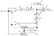
図20は、内部メモリを有する動画像符号化装置のブロック図である。動画像符号化装置23は、MBの符号化に必要な全てのデータを外部メモリ4から読み出してその内部メモリに記憶する。内部メモリは参照領域用メモリ14とバッファメモリ15の2種類ある。動き検出の時に参照される参照画像は参照領域用メモリ14に記憶され、参照領域用メモリ14から動き検出部16と動き補償部17に供給される。符号化のために必要なその他のデータはバッファメモリ15に記憶され、動き検出部16、動き補償部17、イントラ予測部18、整数変換・量子化・逆量子化・逆整数変換部19、可変長符号化部20、デブロッキングフィルタ部21はバッファメモリ15との間でデータを転送する。制御部22はイントラ・インター判定とレート制御を行う。制御部22はワイヤードロジックまたはマイクロプロセサで構成される。なお、図20では参照領域用メモリ14とバッファメモリ15を別々のものとして表わしたが、参照領域用アドレスとバッファ用アドレスが別れていれば1個の共通メモリであっても良い。(Sixth embodiment)
FIG. 20 is a block diagram of avideo encoding apparatus having an internal memory. The moving
図21は、縦に連続する4つのMB行に含まれる4個のMBを1個のMBパイプラインで処理する場合の参照領域を示した説明図である。参照領域28、29、30、31はそれぞれMB24、25、26、27の動き検出のときに参照される領域である。参照領域28、29、30、31は大きく重なっており、縦に隣り合うMB行に属する2個のMBの参照領域において重なっていない部分の高さはMBの縦方向の画素数と一致する。この重なり部分は動きベクトルの検出範囲が広くなるほど大きくなる。本実施形態において参照領域28、29、30、31中の全画素は、参照領域用メモリ14に記憶される。従来技術と同様に、本実施形態でも右方向に隣接するMBの符号化を開始するとき、外部メモリ4から参照領域用メモリ14へ更新領域32、33、34、35のみ転送し、それまで符号化していた左隣接MBの参照領域28、29、30、31の原点から次に符号化する右隣りのMBのための新しい原点に付け替える。ただし、MB25のための更新領域33は、MB24の参照領域28に含まれていない部分のみである。同様に、MB26とMB27の更新領域34、35はそれぞれMB25とMB26の参照領域29、30に含まれていない部分のみである。従って、従来技術に比べて、外部メモリ4と参照領域用メモリ14の間の画素転送量を大幅に削減することができる。FIG. 21 is an explanatory diagram showing a reference area when four MBs included in four vertically continuous MB rows are processed by one MB pipeline.
図22は、参照領域用メモリに参照領域を記憶するもう一つの方法を示した説明図である。参照領域用メモリ14には、参照領域28、29、30、31を全て含む矩形の領域36を記憶する。この方法によれば、参照領域用メモリ14のアドレス生成が簡単になる。また、更新領域37もひとまとまりの矩形領域となるため、外部メモリ4から参照領域用メモリ14への画素の転送が簡単になる。FIG. 22 isan explanatory diagram showing another method of storing the reference area in the reference area memory . The
上記では、連続した4つのMB行に含まれる4つのMBを1個のMBパイプラインで同時に処理する場合を例として示したが、本実施形態に示す方法は連続した2以上のMB行であれば適用でき、例えば連続した8のMB行であっても良い。In the above, the case where four MBs included in four consecutive MB rows are simultaneously processed by one MB pipeline has been shown as an example. However, the method shown in the present embodimentmay be performed on two or more consecutive MB rows. For example, it may be eight consecutive MB lines.
なお、参照領域用メモリ14には単画素精度画像のみ記憶し、参照領域用メモリ14から読み出した単画素精度画像から動き検出部16と動き補償部17の内部で半画素精度画像や1/4画素精度画像を作成する構成とすることができる。この構成は、予め半画素精度画像や1/4画素精度画像を作成して外部メモリ4に記憶し、外部メモリ4から参照領域用メモリ14に半画素精度画像や1/4画素精度画像を転送する構成よりも外部メモリ4と参照領域用メモリ14の間の画素転送量を削減することができる。 The
また、2画素精度画像等の縮小画像を作成し、最初に縮小画像上で動き検出を行い、段階的に高精度画像で動き検出を行う階層的探索法がある。この探索法に対して本発明を適用する場合にも、参照領域用メモリ14には単画素精度画像のみを記憶しておき、動き検出部16と動き補償部17の内部で縮小画像を作成する構成とすることができる。この構成は、予め縮小画像を作成して外部メモリ4に記憶し、外部メモリ4から参照領域用メモリ14に縮小画像を転送する構成よりも外部メモリ4と参照領域用メモリ14の間の画素転送量を削減することができる。 Further, there is a hierarchical search method in which a reduced image such as a two-pixel accuracy image is created, motion is first detected on the reduced image, and motion detection is performed on the high-accuracy image step by step. Even when the present invention is applied to this search method, only the single-pixel precision image is stored in the
その他、動き検出における演算量を削減する手法としてテレスコピック探索法が提案されている。テレスコピック探索法では、符号化対象画像と参照画像の中間の画像も必要となる。この場合には、中間の画像の中で動き検出に必要な領域に対しても本実施形態に示す更新方法を適用することができる。In addition, a telescopic search method has been proposed as a method for reducing the amount of calculation in motion detection. In the telescopic search method, an intermediate image between the encoding target image and the reference image is also required. In this case, it is also possible to apply the update method shown in the presentembodiment, onthe space required for the motion detection in the middle of the image.
また、輝度信号だけを本実施形態に示す方法で外部メモリ4から画像符号化装置23の内部メモリに転送しても良いし、輝度信号と色差信号の両方に本実施形態に示す方法を適用しても良い。なお、動き検出のときに色差信号を参照しない場合には、色差信号は参照領域用メモリ14とバッファメモリ15のどちらに記憶しても良い。Also, it may be transferred from the
(第7の実施形態)
HDTV映像を符号化対象とする場合、良好な画質を得るために動きベクトルの範囲は横±200画素、縦±100画素程度必要である。この範囲の動きベクトルを検出するための演算量は膨大であり、動き検出のために多くのサイクル数を要する。しかし、MBパイプライン構造の動画像符号化装置では、MBサイクル当たりのサイクル数は全てのステージで共通である。動き検出のためのステージのみMBサイクル当たりのサイクル数を増加させることはできない。また、本発明を適用したMBパイプラインでは、処理結果をフィードバックできるステージ数に限界があるため、MBパイプラインのステージ数を増加させることは好ましくない。(Seventh embodiment)
When HDTV video is to be encoded, the motion vector range needs to be about ± 200 pixels horizontally and ± 100 pixels vertically to obtain good image quality. The amount of calculation for detecting a motion vector in this range is enormous, and a large number of cycles are required for motion detection. However, in a moving picture encoding apparatus having an MB pipeline structure, the number of cycles per MB cycle is common to all stages. Only the stage for motion detection cannot increase the number of cycles per MB cycle. Also, in the MB pipeline to which the present invention is applied, there is a limit to the number of stages where the processing result can be fed back, so it is not preferable to increase the number of stages in the MB pipeline.
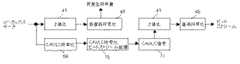
図23は広い範囲で動きを検出できる動き検出装置38と、本発明が適用されたMBパイプラインを含む動画像符号化装置23の組み合わせを示す。動き検出装置38は、動きベクトルの符号化コストを考慮せず、予測誤差の符号化コストのみを考慮して動きベクトル候補を検出する。動画像符号化装置23は、動き検出装置38で検出された動きベクトル候補を受け取って、その動きベクトル候補の周辺領域について動きベクトルの符号化コストまで考慮して動き検出を行う。すなわち、広い範囲でPMVを参照せずに動きを検出し、検出された動きベクトル候補の周辺領域についてPMVを参照して再度動き検出を行う。受け取った動きベクトル候補の周辺領域における再度の動き検出は2画素精度動き検出や単画素精度動き検出等任意の精度の動き検出段階で行うことが可能である。動画像符号化装置23では、この動きベクトル候補の周辺領域に加えて、コスト最小の動きベクトルが存在する可能性が高い他の領域、例えばPMVの周辺領域でも同時に動き検出を行っても良い。動き検出装置38は、動画像符号化装置23のMBパイプラインと無関係に動作するため、多くのサイクル数をかけて動き検出を行うことができる。 FIG. 23 shows a combination of a
また、動き検出装置38は、動画像符号化装置23で作成された再生画像ではなく、符号化されていない入力されたままの画像を対象として動き検出を行う構成とすることもできる。この構成とすることにより、動画像符号化装置23から動き検出装置38に再生画像を送る必要が無くなる。 In addition, the
なお、動き検出装置38と動画像符号化装置23を同一のLSI上に集積することも可能である。この場合、動画像符号化装置23に接続されている外部メモリ4を動き検出装置38と動画像符号化装置23の共有メモリとし、動き検出装置38は再生画像を対象として動き検出を行う構成としても良い。 It is possible to integrate the
また、MPEG−2からH.264へトランスコードするときのように、既に検出された動きベクトルを利用できるときには、動き検出装置38を用いず、検出済の動きベクトルを直接動画像符号化装置23に入力し、この検出済み動きベクトルの周辺領域について動きベクトルの符号化コストまで考慮して動き検出を行う構成とすることもできる。 Also, MPEG-2 to H.264. When the already detected motion vector can be used as in the case of transcoding to H.264, the detected motion vector is directly input to the moving
(第8の実施形態)
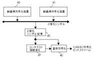
2つの動画像符号化装置40、41と内部メモリ39を有する並列動画像符号化装置42のブロック図を図24に示す。図25は、動画像符号化装置40と41が符号化を分担するピクチャの領域を示す。i−MB行〜l−MB行、q−MB行〜t−MB行等を動画像符号化装置40が分担して符号化し、e−MB行〜h−MB行、m−MB行〜p−MB行等を動画像符号化装置41が分担して符号化する。このピクチャ分割方法によれば、動画像符号化装置40と41の分担するピクチャの領域が縦に連続しているため、両者の参照領域は縦に大きく重なっている。外部メモリ4から内部メモリ39へ2つの動画像符号化装置40と41の参照領域を転送し、内部メモリ39から個々の動画像符号化装置40と41に転送する構成とすれば、両者の参照領域の重なり部分を重複して転送する必要がないため、外部メモリ4と内部メモリ39の間のデータ転送量を削減することができる。(Eighth embodiment)
FIG. 24 shows a block diagram of a parallel
動画像符号化装置40と41に含まれるMBパイプラインの各ステージをMBが流れていく様子を図26に示す。各々の動画像符号化装置40と41のステージ構成は第1の実施形態の動画像符号化装置と同一である。ただし、例えば、l−MB行に属するMBの再生画素と動きベクトルを動画像符号化装置40から動画像符号化装置41に転送し、m−MB行に属するMBの符号化で参照することが可能である。このように、動画像符号化装置40と41の分担する領域の境界において、上隣接MBと右上隣接MBにおける再生画素や動きベクトル等現MBの参照するデータを転送できるタイミングで動画像符号化装置40と41を動作させる。このように動作させることにより、従来のスライスインタリーブと異なり、本実施形態の方法によれば、図25のi−MB行〜l−MB行やm−MB行〜p−MB行のように各動画像符号化装置40と41が分担して符号化する領域ごとにスライス分割する必要はなく、ピクチャ全体を1スライスとすることも可能である。更に、a−MB行〜d−MB行やe−MB行〜h−MB行等動画像符号化装置40と41が処理するピクチャの最初の領域が入力されると、動画像符号化装置40と41は符号化を開始することができるので、符号化遅延を抑えることができる。FIG. 26 shows how the MB flows through each stage of the MB pipeline included in the moving
なお、並列動画像符号化装置42は3個以上の動画像符号化装置を含んでいても良い。 The parallel
(第9の実施形態)
H.264では可変長符号化の方法としてCABACを用いることができる。CABACは、1個の算術符号化回路を使用して1つのスライスに含まれる全MBを連続的に処理する。一方、第1の実施形態〜第8の実施形態に記載した発明では、縦に連続する複数のMB行をひとまとまりとして、これらひとまとまりのMB行から、1つのMB行当たり1個のMBを選択し、これら選択された複数のMBを1個のMBパイプラインに連続して投入する。このため、縦に連続するひとまとまりのMB行に含まれる全てのMBの符号化が終了した後でなければ2値化シンボルを算術符号化することができない。しかし、あるMBを符号化したとき、その発生符号量が著しく多い場合がある。このような場合、早急に量子化パラメータを大きくし、新たに符号化するMBから発生する符号量を減少させるようにレート制御しなければならない。本実施形態では、第1の実施形態〜第8の実施形態に記載した発明が適用された動画像符号化装置においてH.264で規定されるCABAC等の算術符号化を行う場合に、縦に連続するひとまとまりのMB行に含まれる全てのMBの符号化が終了する前にレート制御を行う方法を示す。(Ninth embodiment)
H. In H.264, CABAC can be used as a variable length coding method. CABAC continuously processes all MBs included in one slice by using one arithmetic coding circuit. On the other hand, in the inventions described inthe first to eighth embodiments , a plurality of MB rows that are vertically continuous are taken as a group, and one MB per MB row is obtained from the batch of MB rows. A plurality of selected MBs are continuously input to one MB pipeline.For this reason, a binary symbol cannot be arithmetically encoded unless encoding of all MBs included in a group of MBs that are vertically continuous is completed. However, when a certain MB is encoded, the generated code amount may be remarkably large. In such a case, it is necessary to increase the quantization parameter immediately and control the rate so as to reduce the amount of code generated from the newly encoded MB. In the present embodiment,H.264 is applied to the moving picture coding apparatus to which the inventions described in thefirst to eighth embodiments are applied. In the case of performing arithmetic coding such as CABAC defined in H.264, a method is shown in which rate control is performed before the coding of all MBs included in a group of MBs that are vertically continuous is completed.
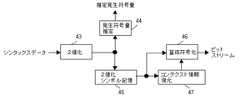
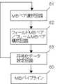
2値化シンボルのシンボル長の総和から算術符号化の発生符号量を推定する方法がある。この方法によって推定される発生符号量によってレート制御を行えば、縦に連続するひとまとまりのMB行に含まれる全てのMBの符号化終了を待たずにレート制御することができる。図27は、推定発生符号量に基づいてレート制御を行うCABAC符号化器のブロック図である。Thereis a method for estimating the generated code amount of arithmetic coding from the total symbol length ofbinary symbols . If rate control is performed based on the generated code amount estimated by this method, rate control can be performed without waiting for the completion of encoding of all MBs included in a group of MBs that are vertically continuous. FIG. 27 is a block diagram of a CABAC encoder that performs rate control based on the estimated generated code amount.
まず、シンタックスデータを2値化回路43により2値化する。2値化回路43は、ルックアップテーブルを含み、テーブルルックアップを用いて2値化シンボルへの変換を1サイクルで行う。そして、発生符号量推定回路44により変換された2値化シンボルのシンボル長の総和からMBごとの発生符号量を推定し、制御部22に推定発生符号量を送ってレート制御を行う。これにより、縦に連続するひとまとまりのMB行に含まれる全てのMBの符号化が終了する前にレート制御を行うことができる。 First, the syntax data is binarized by the
ここで、本発明が適用された動画像符号化装置では、MB行の先頭のMBを処理するとき、その上に隣り合ったMB行の最後のMBの量子化パラメータはまだ求まっていない。しかし、量子化パラメータは直前に符号化したMBの量子化パラメータとの差分が2値化され、算術符号化される。そこで、MB行内の先頭のMBの量子化パラメータについては仮の値との差分(以下、仮mb_qp_deltaという。)を2値化するものとする。なお、仮の値は、既に符号化済みのMBの量子化パラメータを参照して上に隣り合うMB行内の最後のMBの量子化パラメータを推測して決定することが望ましい。一方、MB行内の先頭以外のMBの量子化パラメータは、H.264で規定されている通り、直前に符号化した左隣接MBのものとの差分(以下、mb_qp_deltaという。)を2値化する。 Here, in the moving picture encoding apparatus to which the present invention is applied, when the first MB of the MB row is processed, the quantization parameter of the last MB of the MB row adjacent to it is not yet determined. However, the difference between the quantization parameter and the quantization parameter of the MB encoded immediately before is binarized, and arithmetic coding is performed. Thus, the quantization parameter of the first MB in the MB row is binarized from the temporary value (hereinafter referred to as temporary mb_qp_delta). The provisional value is desirably determined by referring to the quantization parameter of the already encoded MB and estimating the quantization parameter of the last MB in the MB row adjacent above. On the other hand, the quantization parameters of MBs other than the head in the MB row are H.264. As defined in H.264, the difference (hereinafter referred to as mb_qp_delta) from the left adjacent MB encoded immediately before is binarized.
次に、2値化シンボルをいったん2値化シンボル記憶回路45で記憶し、縦に連続するひとまとまりのMB行に含まれる全てのMBの符号化が終了した後、2値化シンボルを2値化シンボル記憶回路45から読み出す。そして、コンテクスト情報復元回路47を用いてそれに対応するコンテクスト情報を復元しながら、算術符号化回路46により算術符号化を行う。コンテクスト情報復元回路47の処理は、動画像復号装置で使用されるCABAC復号回路内のコンテクスト情報復元処理とほぼ同一である。コンテクスト情報復元回路47の処理フローを図28に示す。スライスの先頭でコンテクスト情報を初期化する(ステップS5)。次に、変数tmpをクリアし(ステップS6)、シンタックスデータの2値化シンボルを1個取得する(ステップS7)。その後、算術符号化するsymbolのコンテクスト情報を取得し(ステップS8)、2値化シンボル記憶回路45からsymbolを1ビット読み出す(ステップS9)。そして、コンテクスト情報とsymbolを算術符号化回路46に出力する(ステップS10)。変数tmpを1ビット左論理シフトした後、LSBにsymbolを連結する(ステップS11)。この新たなtmpがステップS7で取得した2値化シンボルと異なる場合にはステップS8に戻る(ステップS12)。tmpが2値化シンボルと一致する場合にはスライスの最後か否か判定し、スライスの最後でない場合にはステップS6に戻り(ステップS13)、tmpをクリアするとともに新たな2値化シンボルを取得する(ステップS6、S7)。スライスの最後である場合にはコンテクスト情報復元処理を終了する(ステップS13)。 Next, the binarized symbols are temporarily stored in the binarized
ただし、MB行内の先頭のMBの仮mb_qp_deltaを2値化シンボル記憶回路45に記憶し、コンテクスト情報復元回路47でMB行内の先頭のMBの量子化パラメータを再現することとすると、上に隣り合うMB行内の最後のMBの量子化パラメータを再現し、それとの差分を算出して実際のmb_qp_deltaを求めた後、再度2値化し、算術符号化しなければならない。その際、そのMB行に含まれる全てのMBについてmb_qp_deltaを復号して量子化パラメータを再現することが必要となる。これを避けるために、MB行内の最後のMBについてはmb_qp_deltaとともに量子化パラメータそのものを2値化シンボル記憶回路45に記憶することとしても良い。MB行内の最後のMBの量子化パラメータを一定のビット長として記憶することにより、コンテクスト情報復元回路47でMB行内の最後のMBの量子化パラメータと識別することができる。However, the temporary mb_qp_delta of the first MB in the MB row is storedin the binarized
なお、2値化シンボル記憶回路45は動画像符号化装置内部に無くても良く、外部メモリ4に2値化シンボルを記憶することとしても良い。 Note that the binarized
本実施形態の方法には、算術符号化回路が突発的に増加する2値化シンボル発生量を処理できるだけの性能を有していなくても算術符号化することができるという利点がある。特に、2値化シンボル記憶回路45にIピクチャの2値化シンボルとその前後のPピクチャやBピクチャの2値化シンボルを記憶できるだけの十分な記憶容量を持たせれば、算術符号化回路46にIピクチャの2値化シンボル発生量を処理できるだけの性能を持たせる必要はなく、複数ピクチャの2値化シンボルの平均発生量を処理できるだけの性能を持たせれば足りるという利点がある。The method of the presentembodiment, there is the advantage that it is possible to arithmetic coding without arithmetic coding circuit have a capability enough to handle binary symbol generation amount increases suddenly. In particular, if the binarized
(第10の実施形態)
本実施形態では、CABACを用いる動画像符号化装置に本発明を適用する場合における第9の実施形態とは別のレート制御方法を示す。図29は、仮の発生符号量に基づいてレート制御を行うCABAC符号化器のブロック図である。2値化シンボルをいったん2値化シンボル記憶回路45に記憶し、2値化シンボル記憶回路45から読み出してそれに対応するコンテクスト情報を復元しながら算術符号化(以下、真の算術符号化という。)を行う点については第9の実施形態と同じである。本実施形態では、2値化シンボルを仮算術符号化回路48により仮算術符号化して仮の発生符号量を算出し、縦に連続するひとまとまりのMB行に含まれる全てのMBの符号化が終了する前に仮の発生符号量に基づいてレート制御する点が異なる。(Tenth embodiment)
In the presentembodiment, a rate control method different from that ofthe ninth embodiment inthe case where the present invention is applied to a moving image encoding apparatus using CABAC is shown. FIG. 29 is a block diagram of a CABAC encoder that performs rate control based on a provisional generated code amount. A binary symbol is temporarily stored in the binary
MB行内の先頭のMBでは、通常上に隣り合うMB行内の最後のMBの算術符号化が終えたときのrange、low、および確率テーブルを引き継いで算術符号化を行う。しかし、本発明では縦に連続する複数のMB行をひとまとまりとして符号化を進めるため、MB行内の先頭のMBを符号化するとき上に隣り合うMB行内の最後のMBは符号化が終わっていない。このため、縦に連続するひとまとまりのMB行の符号化が終了するまで、上に隣り合うMB行内の最後のMBの算術符号化が終えたときのrange、low、および確率テーブルを引き継いで算術符号化を行うことができない。そこで、MB行内の先頭のMBについては仮の値をrange、low、および確率テーブルに設定して仮算術符号化を開始する。 In the first MB in the MB row, arithmetic coding is performed by taking over the range, low, and probability table when the arithmetic coding of the last MB in the adjacent MB row is finished. However, in the present invention, since encoding is performed with a plurality of vertically continuous MB rows as a group, when the first MB in the MB row is encoded, the last MB in the upper adjacent MB row has been encoded. Absent. For this reason, until encoding of a group of consecutive MBs is completed, the arithmetic is performed by taking over the range, low, and probability table when arithmetic coding of the last MB in the adjacent MB row is completed. Encoding cannot be performed. Therefore, for the first MB in the MB row, provisional values are set in the range, low, and probability tables, and provisional arithmetic coding is started.
縦に連続する4つのMB行をひとまとまりとして符号化を行う場合の仮算術符号化回路48のブロック図を図30に示す。コンテクスト計算部49はsymbolごとにコンテキスト計算を行う。rangeを記憶する部分51〜54、lowを記憶する部分55〜58、および確率テーブル59〜62は4つのMB行に対応して4個づつ存在する。range(n)記憶部分51、low(n)記憶部分55、および確率テーブル(n)59は4つのMB行のうち最も上のMB行に対応する。range(n+1)記憶部分52、low(n+1)記憶部分56、および確率テーブル(n+1)60は上から2番目のMB行に対応する。そして、range(n+2)記憶部分53、low(n+2)記憶部分57、および確率テーブル(n+2)61は上から3番目のMB行に対応し、range(n+3)記憶部分54、low(n+3)記憶部分58、および確率テーブル(n+3)62は最も下のMB行に対応する。rangeを記憶する部分51〜54とlowを記憶する部分55〜58の内容は、4つのMB行に含まれる個々のMBの算術符号化を開始するときのみ算術符号化部50に読み込まれ、そのMBの算術符号化を終了するとき算術符号化部50から書き込まれ更新される。FIG. 30 shows a block diagram of the provisional arithmetic encoding circuit 48 in the case where encoding is performed with a group of four consecutive MB rows as a group. The context calculationunit 49 performs context calculation for each symbol. There are four portions 51 to 54 for storing a range, portions 55 to 58 for storing a low, and probability tables 59 to 62 corresponding to four MB rows. The range (n) storage portion 51, the low (n) storage portion 55, and the probability table (n) 59 correspond to the uppermost MB row of the four MB rows. The range (n + 1) storage portion 52, the low (n + 1) storage portion 56, and the probability table (n + 1) 60 correspond to the second MB row from the top. The range (n + 2) storage portion 53, the low (n + 2) storage portion 57, and the probability table (n + 2) 61 correspond to the third MB row from the top, the range (n + 3) storage portion 54, and the low (n + 3) storage. Portion 58 and probability table (n + 3) 62 correspond to the bottom MB row. The contents of the parts 51 to 54 for storing the range and the parts 55 to 58 for storing the low are read into the arithmetic encodingunit 50 only when the arithmetic encoding of individual MBs included in the four MB rows is started. When the MB arithmetic coding is completed, the arithmetic codingunit 50 writes and updates the MB.
MB行内の先頭のMBについて仮のrange、low、および確率テーブルを設定する方法として3つ考えられる。最初の方法は、H.264で規定されている初期化を行う方法である。H.264ではスライスの先頭でrange、low、および確率テーブルを初期化する。MB行内の先頭のMBについて仮算術符号化を開始するとき、この初期化を行う。 There are three possible methods for setting a temporary range, low, and probability table for the first MB in the MB row. The first method is described in H.W. This is a method of performing initialization defined in H.264. H. H.264 initializes the range, low, and probability tables at the beginning of the slice. This initialization is performed when provisional arithmetic coding is started for the first MB in the MB row.
2番目の方法は、縦に連続するひとまとまりのMB行内の個々のMB行ごとに、MB行内の最後のMBの算術符号化が終えたときのrange、low、および確率テーブルを、その下に隣接するひとまとまりのMB行内の対応するMB行における先頭MBに引き継ぐ方法である。縦に連続する4つのMB行をひとまとまりとして符号化を行う場合を図31に示す。図31は12のMB行で構成されるピクチャを示す。ピクチャの最も上のひとまとまりの4つのMB行については、個々のMB行内の最初のMBのrange、low、および確率テーブルはH.264で規定されている方法で初期化する。上から2番目のひとまとまりの4つのMB行に含まれる個々のMB行については、最も上のひとまとまりの4つのMB行に含まれる個々のMB行内の最後のMBの算術符号化が終えたときのrange、low、および確率テーブルを引き継ぐ。同様に、上から3番目のひとまとまりの4つのMB行については、上から2番目のひとまとまりの4つのMB行に含まれる個々のMB行内の最後のMBの算術符号化が終えたときのrange、low、および確率テーブルを引き継ぐ。 In the second method, the range, low, and probability tables when the last MB in the MB row has been arithmetically encoded for each MB row in a group of vertically contiguous MB rows are This is a method of taking over to the first MB in a corresponding MB row in a group of adjacent MBs. FIG. 31 shows a case where encoding is performed with a group of four vertically continuous MB rows. FIG. 31 shows a picture composed of 12 MB rows. For the top four batches of MB in the picture, the range, low, and probability table of the first MB in each MB row is H.264. It is initialized by the method specified in H.264. For the individual MB rows included in the four MB rows in the second group from the top, arithmetic coding of the last MB in the individual MB rows included in the uppermost four MB rows has been completed. Take over the time range, low, and probability table. Similarly, for the 4 MB rows in the third batch from the top, the arithmetic encoding of the last MB in each MB row included in the 4 MB rows in the second batch from the top is finished. Take over the range, low, and probability tables.
3番目の方法は、既に真の算術符号化を終了したピクチャの同じ位置にあるMBが引き継いだrange、low、および確率テーブルと同じものを、MB行内の先頭のMBにおける仮のrange、low、および確率テーブルとして設定する方法である。 The third method is the same as the range, low, and probability table inherited by the MB at the same position in the picture that has already been subjected to true arithmetic coding, and the temporary range, low, And setting as a probability table.
あるMBを符号化しているとき2値化シンボルが突発的に増加し、仮算術符号化回路48の処理能力を超えたときは、そのMBについては途中で仮算術符号化を打ち切り、次のMBの仮算術符号化を開始しても良い。2値化シンボルの発生量が急激に増大した場合には、第9の実施形態と同様に2値化シンボルの発生量により発生符号量を推定し、これから符号化するMBの量子化パラメータを大きくし、2値化シンボルの発生量を減少させる等の方法によりレート制御を行うことができる。このため、突発的に発生する2値化シンボルの最大発生量を処理できるだけの性能を仮算術符号化回路48に持たせる必要はない。また、本実施形態の方法でも、第9の実施形態の方法同様、2値化シンボル記憶回路45に十分な記憶容量を持たせれば、真の算術符号化回路46に複数ピクチャの2値化シンボルの平均発生量を処理できるだけの性能を持たせれば足りるという利点がある。When a certain MB is encoded, the binarized symbols suddenly increase, and when the processing capacity of the provisional arithmetic encoding circuit 48 is exceeded, provisional arithmetic encoding is aborted on the way to the next MB. The provisional arithmetic coding may be started. When the generation amount of binarized symbols increases rapidly, the generated code amount is estimated from the generation amount of binarized symbols as inthe ninth embodiment, and the quantization parameter of the MB to be encoded is increased. In addition, rate control can be performed by a method such as reducing the amount of binarized symbols generated. For this reason, it is not necessary to give the provisional arithmetic coding circuit 48 sufficient performance to handle the maximum amount of binarized symbols that occur unexpectedly. Also in the method of the presentembodiment, as in the method ofthe ninth embodiment , if the binarized
仮算術符号化回路48を複数設けることもできる。図32は、2並列で仮算術符号化を行う場合の仮算術符号化回路68のブロック図である。コンテクスト計算部49と算術符号化部50を2個づつ有する。一方の算術符号化部50には、range(n)記憶部分51、low(n)記憶部分55、確率テーブル(n)59、range(n+2)記憶部分53、low(n+2)記憶部分57、および確率テーブル(n+2)61が接続されており、ひとまとまりの4つのMB行のうち最も上のMB行と上から3番目のMB行に含まれるMBを仮算術符号化する。また、もうひとつの算術符号化部50には、range(n+1)記憶部分52、low(n+1)記憶部分56、確率テーブル(n+1)60、range(n+3)記憶部分54、low(n+3)記憶部分58、および確率テーブル(n+3)62が接続されており、ひとまとまりの4つのMB行のうち上から2番目のMB行と最も下のMB行に含まれるMBを仮算術符号化する。第1の実施形態と類似したMBパイプラインのステージ構成において、図1中のe行10列、f行8列、g行6列、h行4列のMBが各ステージを流れていく様子を図33に示す。このように、2並列で仮算術符号化を行うことにより、1つのMBの仮算術符号化を2MBサイクルかけて行うことができる。なお、図32中のメモリ63、65とメモリ64、66はそれぞれ2値化シンボルとシンタックッスデータを2MBサイクル保持するために設けられている。A plurality of provisional arithmetic encoding circuits 48 may be provided. FIG. 32 is a block diagram of the provisional arithmetic coding circuit 68 when provisional arithmetic coding is performed in two parallel. Two context calculationunits 49 and two arithmetic codingunits 50 are provided. One arithmetic encodingunit 50 includes a range (n) storage portion 51, a low (n) storage portion 55, a probability table (n) 59, a range (n + 2) storage portion 53, a low (n + 2) storage portion 57, and A probability table (n + 2) 61 is connected, and provisional arithmetic coding is performed on the MBs included in the uppermost MB row and the third MB row from the top among a group of four MB rows. The other arithmetic encodingunit 50 includes a range (n + 1) storage portion 52, a low (n + 1) storage portion 56, a probability table (n + 1) 60, a range (n + 3) storage portion 54, and a low (n + 3) storage portion. 58 and a probability table (n + 3) 62 are connected, and provisional arithmetic coding is performed on the MBs included in the second MB row from the top and the lowest MB row among a group of four MB rows.In the MB pipeline stage configuration similar to that ofthe first embodiment , a state in which the MB of
第9の実施形態の方法は、直前の符号化済みピクチャの2 値化シンボル長と発生符号量との比率αが必要である。このため、シーンチェンジ等があった場合、発生符号量の推定が不正確となる。一方、本実施形態の方法は、同一MB行内のMBの算術符号化が行われるにつれて仮算術符号化に用いられる確率テーブルの値が正確なものに収束する。このため、シーンチェンジ等があった場合でも真の算術符号化による発生符号量に基づくレート制御に近いレート制御を行うことができる。The method ofthe ninth embodiment requires a ratio α between the binary symbol length of the immediately previous encoded picture and the generated code amount. For this reason, when there is a scene change or the like, the estimation of the generated code amount becomes inaccurate. On the other hand, the method of the presentembodiment, the value of the probability table used for temporary arithmetic coding as arithmetic coding of the same MB row MB is made to converge to accurate. For this reason, even when there is a scene change or the like, it is possible to perform rate control close to rate control based on the generated code amount by true arithmetic coding.
(第11の実施形態)
シンタックスデータを2値化以外の方法で圧縮していったん記憶した後、シンタックスデータを復元して2値化、算術符号化することもできる。例えば、H.264ではCABACの他にCAVLCも可変長符号化方式として規定されているが、CAVLCは1個のシンタックスデータを1CKで可変長符号化することができる。CAVLCで圧縮する場合のCABAC符号化器のブロック図を図34に示す。シンタックスデータをCAVLC符号化回路69で圧縮して発生したCAVLC符号化ビットストリームをCAVLC符号化ビットストリーム記憶回路70にいったん記憶する。そして、CAVLC符号化ビットストリーム記憶回路70から読み出したCAVLC符号化ビットストリームをCAVLC復号回路71で復号し、復元されたシンタックスデータを2値化回路43により2値化し、算術符号化回路46により算術符号化する。なお、図34には、仮算術符号化を行い、仮発生符号量でレート制御する場合を示したが第9の実施形態で示したように、2値化シンボルのシンボル長の総和から算術符号化の発生符号量を推定し、レート制御しても良い。(Eleventh embodiment)
After the syntax data is compressed by a method other than binarization and temporarily stored, the syntax data can be restored and binarized or arithmetically encoded. For example, H.M. In H.264, in addition to CABAC, CAVLC is defined as a variable-length encoding method, but CAVLC can variable-code one piece of syntax data with 1 CK. FIG. 34 shows a block diagram of a CABAC encoder when compressed by CAVLC. The CAVLC encoded bit stream generated by compressing the syntax data by the CAVLC encoding circuit 69 is temporarily stored in the CAVLC encoded bit
ここで、第9の実施形態で指摘したように、本発明が適用された動画像符号化装置では、MB行の先頭のMBを処理するとき、その上に隣り合ったMB行の最後のMBの量子化パラメータはまだ求まっていない。そこで、第9の実施形態と同様に、MB行内の先頭のMBの量子化パラメータについては仮の値との差分(以下、仮mb_qp_deltaという。)をCAVLCで符号化し、MB行内の先頭以外のMBの量子化パラメータは直前に符号化した左隣接MBのものとの差分(以下、mb_qp_deltaという。)をCAVLCで符号化するものとする。そして、MB行内の先頭のMBの量子化パラメータについては、上隣接MB行内の最後のMBの量子化パラメータを再現し、それとの差分を算出して実際のmb_qp_deltaを求めた後、2値化し、算術符号化する。その際、全てのMBについてmb_qp_deltaを復号して量子化パラメータを再現することを避けるために、MB行内の最後のMBについてmb_qp_deltaとともに量子化パラメータそのものをCAVLC符号化ビットストリーム記憶回路70に記憶することとしても良い。Here, as pointed out inthe ninth embodiment , in the video encoding apparatus to which the present invention is applied, when the first MB of the MB row is processed, the last MB of the adjacent MB row is processed. The quantization parameter of is not yet determined. Thus, as inthe ninth embodiment , the difference between the quantization parameter of the first MB in the MB row and the temporary value (hereinafter referred to as temporary mb_qp_delta) is encoded by CAVLC, and the MBs other than the first MB in the MB row. As for the quantization parameter of, the difference (hereinafter referred to as mb_qp_delta) from that of the left adjacent MB encoded immediately before is encoded by CAVLC. Then, with respect to the quantization parameter of the first MB in the MB row, the quantization parameter of the last MB in the upper adjacent MB row is reproduced, and the difference between them is calculated to obtain the actual mb_qp_delta, and then binarized. Perform arithmetic coding. At that time, in order to avoid decoding mb_qp_delta for all MBs and reproducing the quantization parameter, the quantization parameter itself is stored in the CAVLC encoded
シンタックスデータを圧縮し、復元できる可逆圧縮方法であれば、CAVLC以外の方法を用いることもできる。すなわち、シンタックスデータを可逆圧縮して圧縮されたシンタックスデータをいったん記憶する。そして、この圧縮されたシンタックスデータを読み出してシンタックスデータを復元する。この復元されたシンタックスデータを2値化シンボルに変換し、算術符号化する。 Any method other than CAVLC can be used as long as it is a reversible compression method capable of compressing and restoring syntax data. That is, syntax data compressed by lossless compression of syntax data is temporarily stored. Then, the compressed syntax data is read to restore the syntax data. The restored syntax data is converted into a binary symbol and arithmetically encoded.
H.264では、entropy_coding_mode_flagを指定することにより、ピクチャごとにCAVLCとCABACを切り替えることができる。そこで、可逆圧縮方法としてCAVLCを用いる場合には、あるMBの2値化シンボルの発生量が突発的に増加し、仮算術符号化した結果真の算術符号化回路46の処理能力を超えると予測されるとき、そのMBを含むピクチャ全体をCAVLC符号化し、一方、仮算術符号化した結果真の算術符号化回路46で処理できると予測されるとき、そのMBを含むピクチャ全体をCABAC符号化することができる。これにより、真の算術符号化回路46の性能が不測するという状況を確実に回避できる。 H. In H.264, CAVLC and CABAC can be switched for each picture by specifying entropy_coding_mode_flag. Therefore, when CAVLC is used as the lossless compression method, the amount of binarized symbols generated for a certain MB suddenly increases, and it is predicted that the processing capacity of the true
また、CAVLC符号化回路69でCAVLC符号化ビットストリームの符号量を算出し、CAVLC符号化と仮算術符号化の仮発生符号量を比較して、ピクチャごとに発生符号量が少ないと推測されるエントロピー符号化モードを選択することもできる。 Further, the CAVLC encoding circuit 69 calculates the code amount of the CAVLC encoded bit stream, and compares the CAVLC encoding and the provisional generated code amount of the provisional arithmetic encoding, and it is estimated that the generated code amount is small for each picture. An entropy coding mode can also be selected.
(第12の実施形態)
本実施形態では、第8の実施形態で示した2つの動画像符号化装置40と41で構成される並列動画像符号化装置42からCABACで符号化された1本のビットストリームを生成する方法を示す。動画像符号化装置40と41から2値化シンボルが出力される並列動画像符号化装置のブロック図を図35に示す。動画像符号化装置40と41から出力される2値化シンボルを共通の2値化シンボル記憶回路45にいったん記憶する。そして、2値化シンボルを2値化シンボル記憶回路45から読み出し、コンテクスト情報復元回路47を用いてそれに対応するコンテクスト情報を復元しながら、算術符号化回路46により算術符号化を行う。(Twelfth embodiment)
In the presentembodiment , a method of generating one bit stream encoded by CABAC from the parallel moving
また、動画像符号化装置40と41からCAVLC符号化ビットストリームが出力される並列動画像符号化装置のブロック図を図36に示す。動画像符号化装置40と41から出力されるCAVLC符号化ビットストリームを共通のCAVLC符号化ビットストリーム記憶回路70にいったん記憶する。そして、CAVLC符号化ビットストリームをCAVLC符号化ビットストリーム記憶回路70から読み出し、CAVLC復号回路71により復号してシンタックスデータに戻した後、そのシンタックスデータを2値化し、算術符号化を行う。 FIG. 36 shows a block diagram of a parallel moving image encoding apparatus in which a CAVLC encoded bit stream is output from the moving
なお、並列動画像符号化装置42は3個以上の動画像符号化装置を含んでいても良い。 The parallel
(第13の実施形態)
H.264のMBAFF(Macroblock Adaptive Frame Field Coding)では、縦に隣接する2つのMBをペア(以下、MBペアという。)とし、16画素×32ラインごとにフィールド符号化とフレーム符号化を切り替えて符号化する。フィールド符号化とフレーム符号化のときのMBペアを図37に示す。図37(a)はフィールド符号化のときのMBペアである。32ラインの画素のうち、奇数ラインでトップフィールドMB72を構成し、偶数ラインでボトムフィールドMB73を構成する。また、図37(b)はフレーム符号化のときのMBペアである。32ラインのうち、上半分の16ラインで上フレームMB74を構成し、下半分の16ラインで下フレームMB75を構成する。トップフィールドMB72とボトムフィールドMB73はお互いに隣接MBの関係にないが、上フレームMB74は下フレームMB75に対して上隣接MBの関係にある。このため、フレーム符号化が選択された場合、下フレームMB75のPMVは上フレームMB74のイントラ/インター判定結果を考慮して決定しなければならないという制限がある。また、下フレームMB75のイントラ予測は上フレームMB74の再生画素を用いるため、上フレームMB74について動き補償が行われ、再生画素が作成されなければ、下フレームMB75についてイントラ予測を行うことができないという制限がある。(13th Embodiment)
H. In H.264 MBAFF (Macroblock Adaptive Frame Field Coding), two vertically adjacent MBs are paired (hereinafter referred to as MB pairs), and encoding is performed by switching between field encoding and frame encoding every 16 pixels × 32 lines. To do. An MB pair at the time of field coding and frame coding is shown in FIG. FIG. 37A shows an MB pair at the time of field coding. Of the 32 lines of pixels, odd lines constitute the top field MB72, and even lines constitute the bottom field MB73. FIG. 37B shows an MB pair at the time of frame coding. Of the 32 lines, the
現MBペアと左隣接MBペアの両方ともフィールド符号化またはフレーム符号化が選択されている場合、現MBペアに含まれる各々のMBの左隣接MBはその左隣りに位置するMBのみである。しかし、現MBペアと左隣接MBペアのフィールド符号化/フレーム符号化の選択が異なる場合、左隣接MBペアに含まれる両方のMBが現MBペアに含まれる個々のMBの左隣接MBとなる。現MBペアはフィールド符号化が選択され、左隣接MBペアはフレーム符号化が選択された場合を図38(a)に示す。トップフィールドMB72の左隣接MBには左隣接MBペアに含まれる上フレームMBの奇数ライン76と下フレームMBの奇数ライン77が対応し、ボトムフィールドMB73の左隣接MBには、上フレームMBの偶数ラインと下フレームMBの偶数ラインが対応する。また、現MBペアはフレーム符号化が選択され、左隣接MBペアはフィールド符号化が選択された場合を図38(b)に示す。上フレームMB74の左隣接MBにはトップフィールドMBの上半分16ライン78とボトムフィールドMBの上半分16ライン79が対応し、下フレームMB75の左隣接MBにはトップフィールドMBの下半分16ラインとボトムフィールドMBの下半分16ラインが対応する。このため、左隣接MBペアに含まれる両方のMBについて動き補償が行われ、再生画素が算出されなければ、現MBペアについてイントラ予測を行うことができないという制限がある。 When field coding or frame coding is selected for both the current MB pair and the left adjacent MB pair, the left adjacent MB of each MB included in the current MB pair is only the MB located on the left side. However, when the field encoding / frame encoding selection of the current MB pair and the left adjacent MB pair is different, both MBs included in the left adjacent MB pair are left adjacent MBs of individual MBs included in the current MB pair. . FIG. 38A shows a case where field encoding is selected for the current MB pair and frame encoding is selected for the left adjacent MB pair. The
本実施形態では、MBAFFの場合に、縦に連続する8のMB行をひとまとまりとして、これらひとまとまりのMB行から、縦に連続する2つのMB行当たり1つのMBペアを選択し、これら選択された4個のMBペアを1個のMBパイプラインに投入する例を示す。図39は、MBパイプラインに投入されるMBペアの例を示した説明図である。ピクチャは図7のものと同一であるが、上述した通りMBAFFではMBペアがフィールド符号化されるかフレーム符号化されるかにより、2つのMBへのラインの割り当てが異なる。そこで、英字の大文字を用いてMBペアを構成するMBを示す。フィールド符号化のときは、I15、K13、M11、O9等はトップフィールドMB72であり、J15、L13、N11、P9等はボトムフィールドMB73である。また、フレーム符号化のときは、I15、K13、M11、O9等は上フレームMB74であり、J15、L13、N11、P9等は下フレームMB75である。In the presentembodiment , in the case of MBAFF, eight MB rows that are vertically continuous are taken as a group, and one MB pair is selected from these batch of MB rows for every two MB rows that are vertically continuous. An example will be shown in which the four MB pairs are input to one MB pipeline. FIG. 39 isan explanatory diagram showing an example of MB pairs to be input to the MB pipeline. The picture is the same as that shown in FIG. 7, but as described above, in MBAFF, line assignment to two MBs differs depending on whether the MB pair is field-coded or frame-coded. Therefore, an MB that constitutes an MB pair is shown using uppercase letters. In the field coding, I15, K13, M11, O9, etc. are the top field MB72, and J15, L13, N11, P9, etc. are the bottom field MB73. In frame encoding, I15, K13, M11, O9, etc. are the upper frame MB74, and J15, L13, N11, P9, etc. are the lower frame MB75.
図40は、第13の実施形態に係る動画像符号化装置のブロック図である。MBペア選択回路81は、例えば、図39に示すようにi−MB行、j−MB行、k−MB行、l−MB行、m−MB行、n−MB行、o−MB行、p−MB行をひとまとまりとし、i−MB行とj−MB行に属するMBペアについては、左下隣接MBペアがまだ選択されていないMBペアを選択し、かつ、k−MB行とl−MB行、m−MB行とn−MB行、o−MB行とp−MB行に属するMBペアについては、右上隣接MBペアが既に選択されているMBペアを選択することによって、I15−J15、K13−L13、M11−N11、O9−P9のMBペアを選択する。フィールドMBペア/フレームMBペア構成回路82は、フィールド符号化が選択されたときは、MBペアの奇数ラインでトップフィールドMB72を構成し、MBペアの偶数ラインでボトムフィールドMB73を構成する。一方、フレーム符号化が選択されたときは、MBペアの上半分のラインで上フレームMB74を構成し、MBペアの下半分のラインで下フレームMB75を構成する。符号化データ設定回路83は、フィールド符号化が選択されたとき、最初に、I15−J15、K13−L13、M11−N11、O9−P9のMBペアに含まれる片方のMBについて、4MBサイクルかけて順番に、1MBサイクルごとに個々のMBを符号化するために必要なデータをMBパイプライン80に設定する。MBを符号化するために必要なデータがMBパイプライン80に設定されると、そのMBはMBパイプライン80に投入される。そして、2回目にI15−J15、K13−L13、M11−N11、O9−P9のMBペアに含まれる残りの片方のMBについて、4MBサイクルかけて順番に、1MBサイクルごとに個々のMBを符号化するために必要なデータをMBパイプライン80に設定する。MBを符号化するために必要なデータがMBパイプライン80に設定されると、そのMBはMBパイプライン80に投入される。また、フレーム符号化が選択されたとき、I15MB、K13MB、M11MB、O9MB、J15MB、L13MB、N11MB、P9MBの順番で、1マクロブロックサイクルごとに個々のMBを符号化するために必要なデータをMBパイプライン80に設定する。MBを符号化するために必要なデータがMBパイプライン80に設定されると、そのMBはMBパイプライン80に投入される。MBペア選択回路81によって選択された最後のMBを符号化するために必要なデータがMBパイプライン80に設定され、そのMBがMBパイプライン80に投入されると、MBペア選択回路81は、I16−J16、K14−L14、M12−N12、O10−P10のMBペアを新たに選択する。FIG. 40 isa block diagram of a video encoding apparatus according to the thirteenth embodiment. For example, as shown in FIG. 39, the MB
図41は、第13の実施形態に係る動画像符号化方法の処理のフローチャートを示す図である。例えば、図39に示すようにi−MB行、j−MB行、k−MB行、l−MB行、m−MB行、n−MB行、o−MB行、p−MB行をひとまとまりとし、i−MB行とj−MB行に属するMBペアについては、左下隣接MBペアがまだ選択されていないMBペアを選択し、かつ、k−MB行とl−MB行、m−MB行とn−MB行、o−MB行とp−MB行に属するMBペアについては、右上隣接MBペアが既に選択されているMBペアを選択することによって、I15−J15、K13−L13、M11−N11、O9−P9のMBペアが選択される(ステップS14)。次に、フィールド符号化が選択されたときは、MBペアの奇数ラインでトップフィールドMB72が構成され、MBペアの偶数ラインでボトムフィールドMB73が構成される。一方、フレーム符号化が選択されたときは、MBペアの上半分のラインで上フレームMB74が構成され、MBペアの下半分のラインで下フレームMB75が構成される(ステップS15、ステップS16、ステップS23)。そして、フィールド符号化が選択されたとき、最初に、I15−J15、K13−L13、M11−N11、O9−P9のMBペアに含まれる片方のMBについて、4MBサイクルかけて順番に、1MBサイクルごとに個々のMBを符号化するために必要なデータがMBパイプライン80に設定される(ステップS17、ステップS18、ステップS19)。MBを符号化するために必要なデータがMBパイプライン80に設定されると、そのMBはMBパイプライン80に投入される。次に、I15−J15、K13−L13、M11−N11、O9−P9のMBペアに含まれる残りの片方のMBについて、4MBサイクルかけて順番に、1MBサイクルごとに個々のMBを符号化するために必要なデータがMBパイプライン80に設定される(ステップS20、ステップS21、ステップS22)。MBを符号化するために必要なデータがMBパイプライン80に設定されると、そのMBはMBパイプライン80に投入される。また、フレーム符号化が選択されたとき、I15MB、K13MB、M11MB、O9MB、J15MB、L13MB、N11MB、P9MBの順番で、1MBサイクルごとに個々のMBを符号化するために必要なデータがMBパイプライン80に設定される(ステップS24、ステップS25、ステップS26、ステップS27、ステップS28、ステップS29)。MBを符号化するために必要なデータがMBパイプライン80に設定されると、そのMBはMBパイプライン80に投入される。選択された最後のMBを符号化するために必要なデータがMBパイプライン80に設定され、そのMBがMBパイプライン80に投入されると、ステップS14に戻り(ステップS21、ステップS28)、I16−J16、K14−L14、M12−N12、O10−P10のMBペアが新たに選択される(ステップS14)。FIG. 41 isa diagram illustrating a flowchart of the process of the moving image coding method according to the thirteenth embodiment. For example, as shown in FIG. 39, i-MB line, j-MB line, k-MB line, l-MB line, m-MB line, n-MB line, o-MB line, and p-MB line are grouped. For the MB pairs belonging to the i-MB row and the j-MB row, the MB pair for which the lower left adjacent MB pair has not yet been selected is selected, and the k-MB row, the l-MB row, and the m-MB row For the MB pairs belonging to the n-MB row, the o-MB row, and the p-MB row, by selecting the MB pair for which the upper right adjacent MB pair has already been selected, I15-J15, K13-L13, M11- The MB pair of N11 and O9-P9 is selected (step S14). Next, when field coding is selected, the top field MB72 is composed of the odd lines of the MB pair, and the bottom field MB73 is composed of the even lines of the MB pair. On the other hand, when frame coding is selected, the upper frame MB74 is configured by the upper half line of the MB pair, and the lower frame MB75 is configured by the lower half line of the MB pair (steps S15, S16, and step S16). S23). When field coding is selected, first, one MB included in the MB pair of I15-J15, K13-L13, M11-N11, and O9-P9 is sequentially repeated every 4 MB cycles for every 1 MB cycle. Data necessary for encoding individual MBs is set in the MB pipeline 80 (step S17, step S18, step S19). When data necessary for encoding an MB is set in the
図42は、8×8SBごとの動きベクトルを検出するために、8つのMB行に含まれるMBペアを1個のMBパイプラインに投入したとき、各MBペアがMBパイプラインの各ステージを流れていく様子を示す。ここで、フィールド画像は縦方向の画素数がフレーム画像の半分であるため、縮小画像を作成するために縦方向について2画素の画素値を平均すると、フィールド画像とフレーム画像では異なる縮小画像となる。一方、縦単画素/横2画素精度の縮小画像では、フレームの縮小画像から奇数ラインを抜き出すとトップフィールドの縮小画像となり、フレームの縮小画像から偶数ラインを抜き出すとボトムフィールドの縮小画像となる。このため、本実施形態では、図42に示すように、ステージ0で縦単画素/横2画素精度の参照領域をメモリに設定し、ステージ1では縦単画素/横2画素精度で動き検出を行う。FIG. 42 shows that when MB pairs included in 8 MB rows are input to one MB pipeline in order to detect a motion vector for each 8 × 8 SB, each MB pair flows through each stage of the MB pipeline. Show how it goes. Here, since the number of pixels in the vertical direction of the field image is half that of the frame image, when the pixel values of two pixels in the vertical direction are averaged to create a reduced image, the reduced image differs between the field image and the frame image. . On the other hand, in the reduced image of the vertical single pixel / horizontal two-pixel accuracy, when an odd line is extracted from the reduced image of the frame, a reduced image of the top field is obtained, and when an even line is extracted from the reduced image of the frame, a reduced image of the bottom field is obtained. Therefore, in the presentembodiment, as shown in FIG. 42, to set the reference region of the vertical single pixel / horizontal half-pixel precision in the memory in
また、本実施形態では、I15、K13、M11、O9等のMBペアの片方のMBが4つ連続してMBパイプラインに投入された後、J15、L13、N11、P9等のMBペアの残りの片方のMBが4つ連続して投入される。このように、MBペアの片方のMBが連続してMBパイプラインに投入されるため、その順番で動きベクトルの参照領域を更新すると、更新領域が不連続となる。そこで、ステージ0で縦単画素/横2画素精度メモリを設定するときは、図22に示すように、8つのMB行の更新領域をひとまとまりの矩形領域として設定する。In thisembodiment , after four MBs in one of the MB pairs such as I15, K13, M11, and O9 are continuously inserted into the MB pipeline, the remaining MB pairs such as J15, L13, N11, and P9 are left. 4 MBs are continuously inserted. Thus, since one MB of the MB pair is continuously input into the MB pipeline, when the motion vector reference area is updated in that order, the update area becomes discontinuous. Therefore, when setting the vertical single pixel / horizontal two-pixel accuracy memory at
また、フィールド符号化とフレーム符号化のいずれかを選択するには、フィールド符号化とフレーム符号化の各々についてイントラ予測とインター予測の両方を行い、予測誤差の小さい符号化モードと予測モードの組合せを選択することが望ましい。しかし、この方法は膨大な演算量を必要とする。一方、現MBペア内の画素のみで符号化モードを判定し、選択された方のみについてイントラ予測とインター予測を行う簡易的な選択法も考えられる。たとえば、32ライン全てについて隣接したライン間で差分絶対値和または差分自乗和を求め、また、1ラインごと、すなわち奇数ライン16本と偶数ライン16本の隣接ライン間で差分絶対値和または差分自乗和を求めて、32ライン全てについて求めた方が小さかったときはフレーム符号化、1ラインごとに求めた方が小さかったときはフィールド符号化とする等の方法である。最適な選択とはならない場合もあるが、演算量は少ない。本実施形態では、簡易的な選択法を用いることとし、ステージ0でフィールド/フレーム判定を行った後、選択された符号化モードについて、図42に示すようにステージ1〜4でインター予測を行い、また、それと並列してステージ3と4で4×4イントラ予測、16×16イントラ予測等を行う。In addition, to select either field coding or frame coding, both intra prediction and inter prediction are performed for each of field coding and frame coding, and a combination of a coding mode and a prediction mode with a small prediction error. It is desirable to select. However, this method requires a huge amount of calculation. On the other hand, a simple selection method is also conceivable in which an encoding mode is determined only with pixels in the current MB pair, and intra prediction and inter prediction are performed only on the selected one. For example, the sum of absolute differences or the sum of squares of differences is calculated between adjacent lines for all 32 lines, and the sum of absolute differences or squares of differences is calculated for each line, that is, between adjacent lines of 16 odd lines and 16 even lines. When the sum is obtained and the value obtained for all 32 lines is smaller, frame coding is performed, and when the value obtained for each line is smaller, field coding is performed. Although it may not be an optimal selection, the amount of computation is small. In thisembodiment , a simple selection method is used, and after performing field / frame determination in
本実施形態では、第2の実施形態〜第4の実施形態と同様に縦に連続した8のMB行をひとまとまりとして処理する。しかし、上記段落0122で指摘したように、フレーム符号化が選択された場合、上フレームMB74は下フレームMB75に対して上隣接MBの関係にある。また、上記段落0123で指摘したように、現MBペアと左隣接MBペアのフィールド符号化/フレーム符号化の選択が異なる場合、左隣接MBペアに含まれる両方のMBが現MBペアに含まれる個々のMBの左隣接MBとなる。このため、上フレームMB74の処理結果を3ステージ分しか下フレームMB75の処理にフィードバックできず、また、左隣接MBペアの処理結果を3ステージ分しか現MBペアの処理にフィードバックできず、縦に連続した4つのMB行をひとまとまりとして処理する第5の実施形態と同様の制限が生じる。In the presentembodiment , as inthe second to fourth embodiments , eight MB rows that are vertically continuous are processed as a group. However, as pointed out in paragraph 0122 above, when frame encoding is selected, the upper frame MB74 is in the relationship of the upper adjacent MB with respect to the lower frame MB75. Also, as pointed out in paragraph 0123 above, when the field encoding / frame encoding selection of the current MB pair is different from that of the left adjacent MB pair, both MBs included in the left adjacent MB pair are included in the current MB pair. It becomes the left adjacent MB of each MB. Therefore, the processing result of the upper frame MB74 can be fed back to the processing of the lower frame MB75 only for three stages, and the processing result of the left adjacent MB pair can be fed back to the processing of the current MB pair only by three stages. Restrictions similar to those inthe fifth embodiment in which four consecutive MB rows are processed as a group are generated.
具体的には、例えば、ステージ5でI15MBのイントラ・インター判定が終了したとき、同時にステージ1においてJ15MBの縦単画素/横2画素精度動き検出も終了する。このため上フレームMB74のイントラ・インター判定結果を下フレームMB75の縦単画素/横2画素精度動き検出に反映できないという制限がある。ただし、図42中に矢印で示すように、上フレームMB74のイントラ・インター判定結果はステージ2以降に反映できる。また、左隣接MBペア、上隣接MBペア、右上隣接MBペア等についてステージ5で確定したイントラ・インター判定結果はステージ1の縦単画素/横2画素精度動き検出に反映できる。そこで、ステージ1においては、左隣接MBペア、上隣接MBペア、右上隣接MBペア等の動きベクトルを参照して仮のPMVを作成し、下フレームMB75内の4つの8×8SB全てが共通にこの仮のPMVを参照して縦単画素/横2画素精度動き検出を行う。そして、ステージ2ではステージ1で検出された縦単画素/横2画素精度の候補動きベクトルの周辺領域を単画素精度メモリに設定し、ステージ3で真のPMVを作成し、ステージ3とステージ4で真のPMVを参照して単画素精度動き検出と1/4画素精度動き検出を行う。 Specifically, for example, when I15 MB intra / inter determination is completed in
図43はステージ3と4におけるSBパイプラインの詳細な動作を示す。1つのMB内に含まれる4つの8×8SBについて0番から3番までシリアルに処理される。このため、単画素精度動き検出と1/4画素精度動き検出では隣接8×8SBの動きベクトルを考慮した真のPMVに基づいて動き検出を行うことができる。 FIG. 43 shows the detailed operation of the SB pipeline in
ただし、本実施形態では、空間ダイレクトアドレスの評価が別途必要となる。ステージ1で仮のPMVに基づいて縦単画素/横2画素精度動き検出が行われ、ステージ2ではステージ1で検出された候補動きベクトルの周辺領域が単画素精度メモリに設定される。ステージ1の仮のPMVとステージ3の真のPMVが異なる場合、ステージ3と4で動き検出する領域に空間ダイレクトアドレスに対応する位置のMBや8×8SB等が含まれない場合がある。そこで、ステージ3およびステージ4と並列に空間ダイレクトアドレスに対応する位置のMBや8×8SBのコストを評価する処理を行う必要がある。However, in the presentembodiment, the evaluation of the spatial direct address required separately. In
4×4イントラ予測のために、8つのMB行に含まれるMBペアを1個のMBパイプラインに投入したとき、個々のMBペアがMBパイプラインの各ステージを流れていく様子を図44に示す。また、図45はステージ3と4におけるSBパイプラインの詳細な動作を示す。ここで、上記段落0122と段落0123で指摘した条件を満たすために、第5の実施形態と同様に動き補償はステージ6で行われる。すなわち、上フレームMB74について動き補償が行われた後に下フレームMB75についてイントラ予測が行われ、かつ、左隣接MBペアに含まれる両方のMBについて動き補償が行われた後に現MBペアについてイントラ予測が行われるという条件を満たすために、動き補償はステージ6で行われる。FIG. 44 shows how each MB pair flows through each stage of the MB pipeline when an MB pair included in 8 MB rows is inserted into one MB pipeline for 4 × 4 intra prediction. Show. FIG. 45 shows the detailed operation of the SB pipeline in
また、ステージ7の可変長符号化による発生符号量の変動を調整するため、量子化パラメータを変更するというレート制御をステージ8で行う必要が生じる場合がある。この場合、第5の実施形態と同様に、ステージ5のイントラ・インター判定において4×4イントラ予測モードを選択しないようにするか、または4×4イントラ予測モードが選択されたときはステージ6で新しい量子化パラメータを用いて整数変換・量子化・逆量子化・逆整数変換をやり直す必要がある。In addition, in order to adjust fluctuations in the amount of generated code due to variable length coding in
なお、本実施形態で示したMBパイプラインのステージ構成は一例であって、他のステージ構成とすることも可能である。そして、ステージ構成が変われば、ひとまとまりとして符号化する縦に連続する複数のMB行の数が同じであっても、動き検出やイントラ予測等における制約は変わる。Incidentally, the stage configuration of MB pipeline shown in the presentembodiment is an example, it is also possible to other stage arrangement. If the stage configuration changes, the constraints in motion detection, intra prediction, and the like change even if the number of vertically continuous MB rows encoded as a group is the same.
また、本実施形態に記載された発明と第6の実施形態〜第12の実施形態に記載された発明を同時に動画像符号化装置に適用することも可能である。It is also possible to apply simultaneously the video encoding apparatus of the invention described in has been the inventionof thesixth to twelfth embodiments of the describedembodiment.
1、80…MBパイプライン、2…MB選択回路、3、83…符号化データ設定回路、14…参照領域用メモリ、15…バッファメモリ、20…可変長符号化部、23、40、41…動画像符号化装置、24、25、26、27…MB、28、29、30、31、36…参照領域、32、33、34、35、37…更新領域、28、29、30、34を全て含む矩形の領域、39…内部メモリ、42…並列動画像符号化装置、43…2値化回路、44…発生符号量推定回路、45…2値化シンボル記憶回路、46…算術符号化回路、47…コンテクスト情報復元回路、48…仮算術符号化回路、68…2並列で仮算術符号化を行う仮算術符号化回路、69…CAVLC符号化回路、70…CAVLC符号化ビットストリーム記憶回路、71…CAVLC復号回路、72…トップフィールドMB、73…ボトムフィールドMB、74…上フレームMB、75…下フレームMB、76…上フレームMB奇数ライン、77…下フレームMB奇数ライン、78…トップフィールドMB上半分16ライン、79…ボトムフィールドMB上半分16ライン、81…MBペア選択回路、82…フィールドMBペア/フレームMBペア構成回路 DESCRIPTION OF
Claims (8)
Translated fromJapanese動画像符号化の処理が少なくとも2つの処理に分割され、当該分割された処理を行うステージが少なくとも2ステージ含まれ、当該ステージの中にシンタックスエレメントを可逆圧縮して圧縮されたシンタックスエレメントを生成する可変長符号化ステージが含まれるマクロブロックパイプラインを含み、
縦方向に連続する少なくとも2行であって、ピクチャ全体に含まれる前記マクロブロック行の総行数よりも少ない行数の前記マクロブロック行をひとまとまりとして選択し、
前記ひとまとまりのマクロブロック行の中の最も上のマクロブロック行に含まれるマクロブロックを前記マクロブロックパイプラインに投入し、
前記ひとまとまりのマクロブロック行の中の上から2行目のマクロブロック行に含まれるマクロブロックから最も下のマクロブロック行に含まれるマクロブロックまで順番に、各マクロブロック行の上に隣接したマクロブロック行に含まれる直前投入マクロブロックが前記マクロブロックパイプラインに投入された後に、当該各マクロブロック行に含まれ、当該直前投入マクロブロックより左に位置し、かつ当該直前投入マクロブロックが右上隣接マクロブロックではないマクロブロックを、前記マクロブロックパイプラインに投入する
動画像符号化部と、
前記可変長符号化ステージにおいて前記圧縮されたシンタックスエレメントが書き込まれる圧縮シンタックスエレメント記憶部と、
前記ひとまとまりのマクロブロック行の中の最も上のマクロブロック行について左端のマクロブロックから右端のマクロブロックまで順番に前記圧縮シンタックスエレメント記憶部から前記圧縮されたシンタックスエレメントが読み出され、前記ひとまとまりのマクロブロック行の中の上から2行目のマクロブロック行から最も下のマクロブロック行まで順次、各マクロブロック行について左端のマクロブロックから右端のマクロブロックまで順番に前記圧縮シンタックスエレメント記憶部から前記圧縮されたシンタックスエレメントが読み出され、当該読み出された圧縮されたシンタックスエレメントから前記シンタックスエレメントを復元するシンタックスエレメント復元部と、
前記復元されたシンタックスエレメントを2値化シンボルに変換する2値化部と、
前記変換された2値化シンボルを算術符号化する算術符号化部と
を有する動画像符号化装置。In a macroblock row, which is a collection of macroblocks arranged in a row in the horizontal direction from the left end to the right end of a picture, start encoding from the leftmost macroblock, and sequentially encode the macroblocks adjacent to the right A moving image encoding unit,
The video encoding process is divided into at least two processes, and at least two stages for performing the divided processes are included, and a syntax elementcompressed by lossless compression of the syntax element is included in the stage. Including a macroblock pipeline that includesa variable length encoding stage togenerate ,
Selecting the macroblock rows as a group with at least two rows that are continuous in the vertical direction and having a number of rows smaller than the total number of the macroblock rows included in the entire picture;
Injecting the macroblock included in the top macroblock row in the group of macroblock rows into the macroblock pipeline;
Macros adjacent on each macroblock row in order from the macroblock included in the second macroblock row from the top to the macroblock included in the bottommost macroblock row in the group of macroblock rows. After the previous input macroblock included in the block row is input to the macroblock pipeline, it is included in each macroblock row and is located to the left of the previous input macroblock, and the previous input macroblock is adjacent to the upper right. A video encoding unit that inputs macroblocks that are not macroblocks into the macroblock pipeline;
A compressed syntax element storage unit in which the compressed syntax element is written in the variable length encoding stage;
The compressed syntax elements are read from the compressed syntax element storage unit in order from the leftmost macroblock to the rightmost macroblock for the uppermost macroblock row in the group of macroblock rows, The compression syntax elements in a group of macroblock rows from the top to the bottom macroblock row from the top to the bottom macroblock row, in order from the leftmost macroblock to the rightmost macroblock for each macroblock row A syntax element restoration unit that reads the compressed syntax element from the storage unit and restores the syntax element from the read compressed syntax element;
A binarization unit that converts the restored syntax element into a binarized symbol;
A video encoding apparatus comprising:an arithmetic encoding unit that arithmetically encodes the converted binary symbol .
前記可変長符号化ステージが、前記シンタックスエレメントをCAVLCで圧縮する
請求項1に記載の動画像符号化装置。The moving image encoding process is performed according to the moving image encoding standard H.264. H.264,
The variable length encoding stage compresses the syntax element with CAVLC.
The moving image encoding apparatus according to claim 1 .
動画像符号化の処理が4以上の処理に分割され、当該分割された処理を行うステージが4ステージ以上含まれ、当該ステージの中にシンタックスエレメントを可逆圧縮して圧縮されたシンタックスエレメントを生成する可変長符号化ステージが含まれるマクロブロックパイプラインを含み、
縦方向に連続する2組以上の前記マクロブロック行の組であって、ピクチャ全体に含まれる前記マクロブロック行の組の総数よりも少ない数の前記マクロブロック行の組をひとまとまりとして選択し、
前記ひとまとまりのマクロブロック行の組の中の最も上に位置するマクロブロック行の組に属するマクロブロックペアをフレーム符号化とフィールド符号化のいずれで符号化するか選択し、フレーム符号化を選択したときは当該マクロブロックペアに含まれる上フレームマクロブロックを前記マクロブロックパイプラインに投入し、フィールド符号化を選択したときは当該マクロブロックペアに含まれる片方のマクロブロックを前記マクロブロックパイプラインに投入し、
前記ひとまとまりのマクロブロック行の組の中の上から2番目のマクロブロック行の組から最も下に位置するマクロブロック行の組まで順番に、各マクロブロック行の組の上に隣接したマクロブロック行の組に属するマクロブロックペアに含まれる直前投入マクロブロックが前記マクロブロックパイプラインに投入された後に、当該各マクロブロック行の組に属し、当該直前投入マクロブロックを含むマクロブロックペアより左に位置し、かつ当該直前投入マクロブロックを含むマクロブロックペアが右上隣接マクロブロックペアではないマクロブロックペアをフレーム符号化とフィールド符号化のいずれで符号化するか選択し、フレーム符号化を選択したときは当該マクロブロックペアに含まれる上フレームマクロブロックを前記マクロブロックパイプラインに投入し、フィールド符号化を選択したときは当該マクロブロックペアに含まれる片方のマクロブロックを前記マクロブロックパイプラインに投入し、
前記ひとまとまりのマクロブロック行の組の中の最も下に位置するマクロブロック行の組に属するマクロブロックペアに含まれるマクロブロックが前記マクロブロックパイプラインに投入された後に、前記ひとまとまりのマクロブロック行の組みの中の最も上に位置するマクロブロック行の組から最も下に位置するマクロブロック行の組まで順番に、各マクロブロック行の組に属し、片方のマクロブロックのみ前記マクロブロックパイプラインに投入済みである前記マクロブロックペアに含まれる、まだ前記マクロブロックパイプラインに投入されていない他の片方のマクロブロックを前記マクロブロックパイプラインに投入する
動画像符号化部と、
前記可変長符号化ステージにおいて前記圧縮されたシンタックスエレメントが書き込まれる圧縮シンタックスエレメント記憶部と、
前記ひとまとまりのマクロブロック行の組の中の最も上のマクロブロック行の組について左端のマクロブロックペアから右端のマクロブロックペアまで順番に前記圧縮シンタックスエレメント記憶部から前記圧縮されたシンタックスエレメントが読み出され、前記ひとまとまりのマクロブロック行の組の中の上から2番目のマクロブロック行の組から最も下に位置するマクロブロック行の組まで順次、各マクロブロック行の組について左端のマクロブロックペアから右端のマクロブロックペアまで順番に前記圧縮シンタックスエレメント記憶部から前記圧縮されたシンタックスエレメントが読み出され、当該読み出された圧縮されたシンタックスエレメントから前記シンタックスエレメントを復元するシンタックスエレメント復元部と、
前記復元されたシンタックスエレメントを2値化シンボルに変換する2値化部と、
前記変換された2値化シンボルを算術符号化する算術符号化部と
を有する動画像符号化装置。A set of macroblock rows is created by assembling two macroblock rows, which are a set of macroblocks arranged in a row in the horizontal direction from the left end to the right end of the picture, and adjacent to each other in the vertical direction. A macroblock pair is created by combining two macroblocks adjacent to each other in the vertical direction, and frame encoding and field encoding are selected for each macroblock pair, and encoding is performed. Among them, a video encoding unit that starts encoding from the leftmost macroblock pair and sequentially encodes macroblock pairs adjacent to the right,
The video encoding process is divided into four or more processes, and four or more stages for performing the divided processes are included, and the syntax elementcompressed by reversibly compressing the syntax element is included in the stage.Including a macroblock pipeline that includes a variable length encoding stage to generate,
A set of two or more sets of macroblock rows that are consecutive in the vertical direction, and a set of macroblock rows that is smaller than the total number of sets of macroblock rows included in the entire picture is selected as a group;
Select whether to encode the macroblock pair belonging to the topmost macroblock row set in the group of macroblock rows by frame encoding or field encoding, and select frame encoding When the frame encoding is selected, the upper frame macroblock included in the macroblock pair is input to the macroblock pipeline. When field coding is selected, one macroblock included in the macroblock pair is input to the macroblock pipeline. Throw in,
Macroblocks adjacent to each set of macroblock rows in order from the second set of macroblock rows from the top to the bottom set of macroblock rows in the set of macroblock rows After a previous input macroblock included in a macroblock pair belonging to a set of rows is input to the macroblock pipeline, the macroblock pair belonging to the set of each macroblock row and to the left of the macroblock pair including the previous input macroblock When a macro block pair that is located and the macro block pair including the immediately preceding input macro block is not the upper right adjacent macro block pair is to be encoded by frame encoding or field encoding, and frame encoding is selected Indicates the upper frame macroblock included in the macroblock pair as the macroblock. Tsu put into click pipeline, when you select the field coding charged with macroblocks of one included in the macroblock pair in the macroblock pipeline,
After a macroblock included in a macroblock pair belonging to the lowest set of macroblock rows in the set of macroblock rows is input to the macroblock pipeline, the set of macroblocks The macroblock pipeline belongs to each macroblock row set in order from the topmost macroblock row set to the bottommost macroblock row set in the row set, and only one macroblock belongs to the macroblock pipeline. A video encoding unit that inputs the other macroblock included in the macroblock pair that has already been input to the macroblock pipeline and that has not yet been input to the macroblock pipeline;
A compressed syntax element storage unit in which the compressed syntax element is written in the variable length encoding stage;
The compressed syntax element from the compressed syntax element storage unit in order from the leftmost macroblock pair to the rightmost macroblock pair for the uppermost macroblock row set in the set of macroblock rows. Are sequentially read from the second set of macroblock rows to the lowest set of macroblock rows in the set of macroblock rows, and the leftmost for each set of macroblock rows. The compressed syntax element is read from the compressed syntax element storage unit in order from the macro block pair to the rightmost macro block pair, and the syntax element is restored from the compressed syntax element that has been read. A syntax element restoration unit to perform,
A binarization unit that converts the restored syntax element into a binarized symbol;
A video encoding apparatus comprising:an arithmetic encoding unit that arithmetically encodes the converted binary symbol .
前記可変長符号化ステージが、前記シンタックスエレメントをCAVLCで圧縮するThe variable length encoding stage compresses the syntax element with CAVLC.
請求項5に記載の動画像符号化装置。The moving image encoding apparatus according to claim 5.
Priority Applications (2)
| Application Number | Priority Date | Filing Date | Title |
|---|---|---|---|
| JP2006144890AJP4062711B2 (en) | 2006-04-17 | 2006-05-25 | Video encoding device |
| PCT/JP2007/000292WO2007129433A1 (en) | 2006-04-17 | 2007-03-26 | Dynamic image encoding device and dynamic image encoding method |
Applications Claiming Priority (3)
| Application Number | Priority Date | Filing Date | Title |
|---|---|---|---|
| JP2006113925 | 2006-04-17 | ||
| JP2006113925 | 2006-04-17 | ||
| JP2006144890AJP4062711B2 (en) | 2006-04-17 | 2006-05-25 | Video encoding device |
Related Child Applications (2)
| Application Number | Title | Priority Date | Filing Date |
|---|---|---|---|
| JP2007198211ADivisionJP4095664B2 (en) | 2006-04-17 | 2007-07-30 | Video encoding device |
| JP2007227228ADivisionJP4062712B2 (en) | 2006-04-17 | 2007-09-01 | Moving picture coding apparatus and moving picture coding method |
Publications (2)
| Publication Number | Publication Date |
|---|---|
| JP2007312340A JP2007312340A (en) | 2007-11-29 |
| JP4062711B2true JP4062711B2 (en) | 2008-03-19 |
Family
ID=38667546
Family Applications (1)
| Application Number | Title | Priority Date | Filing Date |
|---|---|---|---|
| JP2006144890AExpired - Fee RelatedJP4062711B2 (en) | 2006-04-17 | 2006-05-25 | Video encoding device |
Country Status (2)
| Country | Link |
|---|---|
| JP (1) | JP4062711B2 (en) |
| WO (1) | WO2007129433A1 (en) |
Families Citing this family (15)
| Publication number | Priority date | Publication date | Assignee | Title |
|---|---|---|---|---|
| JP4182442B2 (en)* | 2006-04-27 | 2008-11-19 | ソニー株式会社 | Image data processing apparatus, image data processing method, image data processing method program, and recording medium storing image data processing method program |
| US8711925B2 (en) | 2006-05-05 | 2014-04-29 | Microsoft Corporation | Flexible quantization |
| JP4939273B2 (en)* | 2007-03-29 | 2012-05-23 | キヤノン株式会社 | Image coding apparatus and image coding method |
| JP4895396B2 (en)* | 2008-01-22 | 2012-03-14 | キヤノン株式会社 | Image decoding apparatus and image decoding method |
| JP5007259B2 (en)* | 2008-03-27 | 2012-08-22 | ルネサスエレクトロニクス株式会社 | Image encoding device |
| US8811486B2 (en) | 2008-04-08 | 2014-08-19 | Nippon Telegraph And Telephone Corporation | Video encoding method, video encoding apparatus, video encoding program and storage medium of the same |
| JP2009267440A (en)* | 2008-04-21 | 2009-11-12 | Canon Inc | Image encoding device and image encoding method |
| US7876257B2 (en)* | 2008-04-28 | 2011-01-25 | Mitsubishi Electric Research Laboratories, Inc. | Method and apparatus for compressing SAR signals |
| US8897359B2 (en) | 2008-06-03 | 2014-11-25 | Microsoft Corporation | Adaptive quantization for enhancement layer video coding |
| WO2011052142A1 (en) | 2009-10-29 | 2011-05-05 | パナソニック株式会社 | Image encoding method and image decoding method |
| US10021409B2 (en)* | 2012-05-09 | 2018-07-10 | Integrated Device Technology, Inc. | Apparatuses and methods for estimating bitstream bit counts |
| EP2814254A1 (en) | 2013-02-21 | 2014-12-17 | ST-Ericsson SA | Combined parallel and pipelined video encoder |
| JP6717562B2 (en)* | 2015-02-06 | 2020-07-01 | パナソニック インテレクチュアル プロパティ コーポレーション オブ アメリカPanasonic Intellectual Property Corporation of America | Image coding method, image decoding method, image coding device, and image decoding device |
| WO2017126331A1 (en)* | 2016-01-21 | 2017-07-27 | ソニー株式会社 | Image processing device and method |
| CN107613301B (en)* | 2017-10-17 | 2020-05-26 | 苏州浪潮智能科技有限公司 | An image processing method and device |
Family Cites Families (5)
| Publication number | Priority date | Publication date | Assignee | Title |
|---|---|---|---|---|
| JPH0837662A (en)* | 1994-07-22 | 1996-02-06 | Hitachi Ltd | Image encoding / decoding device |
| JP4240283B2 (en)* | 2002-10-10 | 2009-03-18 | ソニー株式会社 | Decoding device and decoding method |
| JP4577048B2 (en)* | 2004-03-11 | 2010-11-10 | パナソニック株式会社 | Image coding method, image coding apparatus, and image coding program |
| JP2006005438A (en)* | 2004-06-15 | 2006-01-05 | Sony Corp | Image processor and method thereof |
| KR100624432B1 (en)* | 2004-08-05 | 2006-09-19 | 삼성전자주식회사 | Content-based Adaptive Binary Arithmetic Decoding Method and Apparatus |
- 2006
- 2006-05-25JPJP2006144890Apatent/JP4062711B2/ennot_activeExpired - Fee Related
- 2007
- 2007-03-26WOPCT/JP2007/000292patent/WO2007129433A1/enactiveApplication Filing
Also Published As
| Publication number | Publication date |
|---|---|
| JP2007312340A (en) | 2007-11-29 |
| WO2007129433A1 (en) | 2007-11-15 |
Similar Documents
| Publication | Publication Date | Title |
|---|---|---|
| JP4062711B2 (en) | Video encoding device | |
| JP2007312427A (en) | Video encoding device | |
| TWI759389B (en) | Low-complexity sign prediction for video coding | |
| US20240031610A1 (en) | Image processing device and image processing method | |
| CN100579229C (en) | Method for processing interlaced video with multiple reference pictures | |
| KR101581100B1 (en) | Method for managing a reference picture list, and apparatus using same | |
| JP5368631B2 (en) | Image encoding method, apparatus, and program | |
| JP5219089B2 (en) | Image data generation method | |
| JP5520122B2 (en) | Data converter | |
| JPH11275592A (en) | Moving image code stream converter and its method | |
| JP4609670B2 (en) | Image encoding apparatus, image encoding method and program thereof | |
| US11330275B2 (en) | Image data encoding and decoding | |
| US20210044799A1 (en) | Adaptive resolution change in video processing | |
| US11284105B2 (en) | Data encoding and decoding | |
| WO2010052837A1 (en) | Image decoding device, image decoding method, integrated circuit, and program | |
| US20070133689A1 (en) | Low-cost motion estimation apparatus and method thereof | |
| KR100824161B1 (en) | Image processing unit | |
| JP2006279573A (en) | Encoder and encoding method, and decoder and decoding method | |
| JP5447239B2 (en) | Moving picture coding apparatus and moving picture coding method | |
| JP7359653B2 (en) | Video encoding device | |
| US10142625B2 (en) | Neighbor management for use in entropy encoding and methods for use therewith | |
| JP4062712B2 (en) | Moving picture coding apparatus and moving picture coding method | |
| TWI486908B (en) | Method and associated apparatus for video encoding | |
| WO2017082304A1 (en) | Information compression device, information compression method, recording medium, and encoding device | |
| JP5709492B2 (en) | Image coding method conversion apparatus and image coding method conversion program |
Legal Events
| Date | Code | Title | Description |
|---|---|---|---|
| A521 | Written amendment | Free format text:JAPANESE INTERMEDIATE CODE: A523 Effective date:20070901 | |
| A621 | Written request for application examination | Free format text:JAPANESE INTERMEDIATE CODE: A621 Effective date:20070901 | |
| A871 | Explanation of circumstances concerning accelerated examination | Free format text:JAPANESE INTERMEDIATE CODE: A871 Effective date:20070901 | |
| A975 | Report on accelerated examination | Free format text:JAPANESE INTERMEDIATE CODE: A971005 Effective date:20070925 | |
| A131 | Notification of reasons for refusal | Free format text:JAPANESE INTERMEDIATE CODE: A131 Effective date:20071011 | |
| A521 | Written amendment | Free format text:JAPANESE INTERMEDIATE CODE: A523 Effective date:20071014 | |
| TRDD | Decision of grant or rejection written | ||
| A01 | Written decision to grant a patent or to grant a registration (utility model) | Free format text:JAPANESE INTERMEDIATE CODE: A01 Effective date:20071218 | |
| A61 | First payment of annual fees (during grant procedure) | Free format text:JAPANESE INTERMEDIATE CODE: A61 Effective date:20071222 | |
| R150 | Certificate of patent or registration of utility model | Free format text:JAPANESE INTERMEDIATE CODE: R150 | |
| FPAY | Renewal fee payment (event date is renewal date of database) | Free format text:PAYMENT UNTIL: 20110111 Year of fee payment:3 | |
| LAPS | Cancellation because of no payment of annual fees |