JP4061836B2 - sprocket - Google Patents
sprocketDownload PDFInfo
- Publication number
- JP4061836B2 JP4061836B2JP2000374519AJP2000374519AJP4061836B2JP 4061836 B2JP4061836 B2JP 4061836B2JP 2000374519 AJP2000374519 AJP 2000374519AJP 2000374519 AJP2000374519 AJP 2000374519AJP 4061836 B2JP4061836 B2JP 4061836B2
- Authority
- JP
- Japan
- Prior art keywords
- sprocket
- corrugated portion
- wave
- chain
- corrugated
- Prior art date
- Legal status (The legal status is an assumption and is not a legal conclusion. Google has not performed a legal analysis and makes no representation as to the accuracy of the status listed.)
- Expired - Lifetime
Links
- 230000009467reductionEffects0.000claimsdescription57
- 239000000463materialSubstances0.000claimsdescription37
- 230000002093peripheral effectEffects0.000claimsdescription21
- 238000003780insertionMethods0.000claimsdescription13
- 230000037431insertionEffects0.000claimsdescription13
- 229920001971elastomerPolymers0.000claimsdescription11
- 239000000806elastomerSubstances0.000claimsdescription11
- 239000000853adhesiveSubstances0.000claimsdescription6
- 230000001070adhesive effectEffects0.000claimsdescription6
- 239000002184metalSubstances0.000claimsdescription3
- 239000011295pitchSubstances0.000description10
- 239000011359shock absorbing materialSubstances0.000description6
- 238000005516engineering processMethods0.000description5
- XLYOFNOQVPJJNP-UHFFFAOYSA-NwaterSubstancesOXLYOFNOQVPJJNP-UHFFFAOYSA-N0.000description4
- 230000005540biological transmissionEffects0.000description3
- 230000015572biosynthetic processEffects0.000description3
- 230000008878couplingEffects0.000description3
- 238000010168coupling processMethods0.000description3
- 238000005859coupling reactionMethods0.000description3
- 230000000694effectsEffects0.000description3
- 238000000465mouldingMethods0.000description3
- 229920003051synthetic elastomerPolymers0.000description3
- 229920003002synthetic resinPolymers0.000description3
- 239000000057synthetic resinSubstances0.000description3
- 239000005061synthetic rubberSubstances0.000description3
- 230000001133accelerationEffects0.000description2
- 238000005266castingMethods0.000description2
- 238000004519manufacturing processMethods0.000description2
- 238000000034methodMethods0.000description2
- 230000000116mitigating effectEffects0.000description2
- 230000004043responsivenessEffects0.000description2
- 239000013585weight reducing agentSubstances0.000description2
- 238000004804windingMethods0.000description2
- 230000009471actionEffects0.000description1
- 230000008901benefitEffects0.000description1
- 238000005520cutting processMethods0.000description1
- 230000007423decreaseEffects0.000description1
- 238000010586diagramMethods0.000description1
- 230000005489elastic deformationEffects0.000description1
Images


Classifications
- F—MECHANICAL ENGINEERING; LIGHTING; HEATING; WEAPONS; BLASTING
- F16—ENGINEERING ELEMENTS AND UNITS; GENERAL MEASURES FOR PRODUCING AND MAINTAINING EFFECTIVE FUNCTIONING OF MACHINES OR INSTALLATIONS; THERMAL INSULATION IN GENERAL
- F16H—GEARING
- F16H55/00—Elements with teeth or friction surfaces for conveying motion; Worms, pulleys or sheaves for gearing mechanisms
- F16H55/02—Toothed members; Worms
- F16H55/30—Chain-wheels
- F16H2055/306—Chain-wheels with means providing resilience or vibration damping in chain sprocket wheels
Landscapes
- Gears, Cams (AREA)
Description
Translated fromJapanese【0001】
【発明の属する技術分野】
本発明は、チェーンを介して動力等を伝達する巻掛伝動装置のスプロケットに関する。
【0002】
【従来の技術】
一般に、オートバイや自転車或いは種々の産業機械の動力伝達系において、チェーンとスプロケットとを用いた巻掛伝動装置が広く採用されている。また、チェーン及びスプロケットの形状やサイズに関しては、JIS規格のJISB1801、JISB1802に夫々規定されている。
前記スプロケットにおいては、材料の使用量を少なくしてその製作コストを安価にするためや、オートバイ等においては、車体重量の軽減や、加速時における応答性などの改善のため、所定の配列で複数の軽減孔を形成して、スプロケットの重量を軽減したものもある。また、オートバイの後輪側に設けられるスプロケットは、外部に露出させることも多く、軽減孔の形状によりオートバイの外観が大きく左右されるので、軽減孔の形状やサイズに関しても多数の提案がなされている。
【0003】
【発明が解決しようとする課題】
前述のように軽減孔を設けることにより、スプロケットの重量はかなり軽減できるが、歯の強度、剛性を確保するため、スプロケットの外周端部には軽減孔を形成できないので、現在なされている以上の重量軽減は困難であった。しかも、加速時における応答性の改善のためには、スプロケットの外周側部分を軽量に構成することが好ましいが、前述のように軽減孔ではスプロケットの外周側部分を十分に軽量に構成できないという問題もある。
【0004】
一方、チェーンは、平行配置された2枚のピンリンクプレート及びローラリンクプレートを交互に配して、それを機械的にピン結合した構成になっている関係上、許容し得る引張強度には自ずから限界があり、現在使用しているものよりも幅の狭いものを使用すると、強度的に問題が発生する。それに対して、スプロケットにはチェーンのような機械的な連結部分がなく、しかも、近年、強度、剛性に優れた素材が種々提案されていることから、従来の半分以下の肉厚でも同程度の強度、剛性が得られるようになってきている。
【0005】
そこで、チェーンは、十分な強度を有する現状のサイズのものを使用し、スプロケットのみを薄肉に構成してその重量を全体的に軽減することも考えられるが、スプロケットとチェーン間にスプロケットの厚さ方向へのガタが発生し、噛み合いが円滑になされず騒音の原因になったり、スプロケットやチェーンが偏摩耗したり、偏荷重によりスプロケットやチェーンが捩じれたりする、という問題の発生が懸念される。
【0006】
本発明の目的は、チェーンとの円滑な噛合関係を維持しつつ板厚を全体的に薄肉に構成して軽量化が可能で、しかも捩じれに対する強度を十分に確保できるとともにプレス成形により容易に製作可能で、デザイン的に優れたスプロケットを提供することである。
【0007】
【課題を解決するための手段】
請求項1に係るスプロケットは、板厚をチェーンに対して適正に噛合する適正歯の歯元の厚さの4/5〜1/10に設定した金属板からなり、少なくとも外周部に円周方向に沿って厚さ方向に振幅する波形部を形成するとともに、波形部の波の少なくとも頂部の外端部に歯を形成することで、歯の見かけ上の厚さを適正歯と同じ厚さに設定し、波形部の少なくとも1つの波における頂部間を他の波における頂部間のピッチと異なるピッチに設定し、この波においては頂部の外端部及び頂部間の傾斜部の途中部の外端部に歯を形成したものである。
【0008】
ここで、請求項1記載のスプロケットの波形部は、請求項2記載のように波形部の波の頂部をスプロケットの径方向に放射状に形成したり、請求項3記載のように、波形部の波の頂部をスプロケットの径方向に対して傾斜状に形成したり、請求項4記載のように、波形部の波の頂部をスプロケットの径方向に対して湾曲状に形成することが好ましい実施例である。
スプロケットにおける波形部の形成位置としては、請求項5記載のように、スプロケットの中央部に形成した貫通孔から外周部にかけて形成してもよいし、請求項6記載のように、スプロケットの外周部近傍にのみ形成してもよい。
波形部は、請求項7記載のように、各波の頂部を平坦に形成したり、請求項8記載のように、各波の頂部を折曲状に形成してもよい。また、請求項9記載のように、スプロケットの歯は平板状に形成してもよい。
請求項10記載のように、スプロケットにその重量を軽減するための軽減孔を形成してもよい。軽減孔の形状としては、請求項11乃至12に記載のように、円形や小判形を含む種々の形状のものを採用できる。
【0009】
請求項13記載のように、スプロケットとチェーンとの接触により発生するノイズを低減するためのノイズ低減手段を備えることが好ましい。ノイズ低減手段としては、請求項14乃至15に記載のように、合成ゴムや合成樹脂などのエラストマーからなる緩衝材を採用できる。
ノイズ低減手段は、請求項16記載のようにスプロケットの歯底又は歯底近傍に設けたり、請求項17記載のようにスプロケットの波形部の一部又は全部の溝に充填状に設けたり、請求項18記載のように、スプロケットの波形部の頂部を覆うように設けたり、請求項19記載のように、スプロケットの表裏両面又は片面に設けることが可能であるが、いずれにしても、チェーンに接触すると、ノイズを効果的に低減できるが、ノイズ低減手段の耐久性が低下するので、チェーンに対して接触しないようにしつつ極力接近した位置に設けることが好ましい。
スプロケットに対するノイズ低減手段の固定方法としては、請求項20記載のように接着剤で固定したり、請求項21記載のようにスプロケットの波形部に挿通孔を形成し、挿通孔を介して固定したり、接着剤と挿通孔を併用する固定方法が考えられる。
また、請求項22記載のように、ノイズ低減手段として、環状のエラストマーを用い、このエラストマーをスプロケットの複数の歯に交互に係止させて、スプロケットの歯底付近に位置決め固定してもよい。
【0010】
【作用】
請求項1に係るスプロケットにおいては、スプロケットの少なくとも外周部に、円周方向に沿って厚さ方向に振幅する波形部が形成され、波形部の波の頂部の外端部に歯が形成されているので、スプロケットの歯はチェーンのローラに対してローラの一端側と他端側とに交互に噛合することになり、スプロケットとチェーン間におけるスプロケットの厚さ方向への遊びは常時適正な状態に維持される。つまり、スプロケットの少なくとも外周部に波形部を形成することで、チェーンの強度に応じてスプロケットを薄肉に構成しても、チェーンに噛合するスプロケットの歯の見かけ上の厚さは適正歯の厚さと同じになるので、スプロケットとチェーンとの噛合関係は適正な状態に維持される。しかも、スプロケットに波形部を形成することで、スプロケット全体の捩じれに対する強度、剛性も高くなるし、スプロケットの回転により波形部が空気を切ることになるので、スプロケットの温度上昇も抑制されることになる。更に、スプロケットの使用途中で外面に付着した泥水等は、スプロケットの回転による遠心力でスプロケットとチェーンとの噛合部分へ移動することになるが、スプロケットの少なくとも外周部には波形部を形成してあるので、泥水等は波形部の溝に沿って外部へ効率的に排出され、スプロケットとチェーン間に噛み込まれることはほとんどない。
また、波形部の少なくとも1つの波における頂部間を他の波における頂部間のピッチと異なるピッチに設定し、この波においては頂部の外端部及び頂部間の傾斜部の途中部の外端部に歯を形成し、異なるピッチの波の個数を奇数に設定することで、奇数歯のスプロケットを作製することが可能となる。
【0011】
請求項2乃至3記載のように、波形部の波の頂部をスプロケットの径方向に対して放射状や傾斜状や湾曲状に形成すると、波形部自体がスプロケットの外観を特徴付けるデザインとして作用し、スプロケットの外観が向上する。
また、請求項5記載のように、波形部をスプロケットの中央部の貫通孔から外周部にかけて形成すると、スプロケット全体に占める波形部の面積が大きくなり、波形部の外観が一層強調される。また、請求項6記載のように、波形部をスプロケットの外周部近傍にのみ形成すると、スプロケットの回転時における空気抵抗を極力少なくすることが可能となる。
【0012】
請求項10乃至12に記載のように、軽減孔を形成すると、スプロケットの重量を一層低減することが可能となる。また、軽減孔として円形や小判形の軽減孔を一定の規則で形成すると、軽減孔自体がスプロケットの外観を特徴付けるデザインとして作用し、スプロケットの外観が向上する。
【0013】
請求項13乃至22記載のように、スプロケットにノイズ低減手段を設けると、スプロケットとチェーンとの接触により発生するノイズを低減して、チェーン駆動時における静粛性を高めることが可能となる。
請求項14乃至15に記載のように、ノイズ低減手段としては、合成ゴムや合成樹脂などのエラストマーからなる緩衝材を用いる場合には、緩衝材が弾性変形することにより、スプロケットとチェーンとが接触することによる振動エネルギーと衝突エネルギーが吸収され、チェーン駆動時におけるノイズが低減されることになる。
【0014】
請求項16記載のように、ノイズ低減手段をスプロケットの歯底又は歯底近傍に設ける場合には、ノイズ低減手段をスプロケットに噛合するチェーンに接近配置させることが可能で、チェーン駆動時におけるノイズを効率的に低減できる。
請求項17乃至18記載のように波形部に対してノイズ低減手段を設けると、波形部の溝に充填されたノイズ低減手段がアンカーとして機能するので、スプロケットに対するノイズ低減手段の結合強度が高くなる。
ノイズ低減手段は、請求項20記載のように、接着剤でスプロケットに対して固定することも可能であるが、請求項21記載のように、スプロケットの波形部に挿通孔を形成し、挿通孔を介して固定すると、スプロケットに対するノイズ低減手段の取り付け強度を一層向上できるばかりでなく、ノイズの低減効果にも優れる。
また、請求項22記載のように、ノイズ低減手段として、環状のエラストマーを用い、このエラストマーをスプロケットの複数の歯に交互に係止させて、スプロケットの歯底付近に位置決め固定すると、スプロケットに対するノイズ低減手段の組付けが容易になる。
【0015】
【発明の実施の形態】
以下、本発明の実施例を図面を参照しながら説明する。
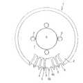
図1〜図8に示すスプロケット1は、円板状の金属製の板状の部材をプレス成形して製作され、各部の板厚は略同じに設定されている。但し、鋳造等により製作することも可能である。
スプロケット1の外端部から中心部に向かって半径の約1/3の範囲には円周方向に一定周期で厚さ方向に振幅する波形部2が折曲状に形成され、波形部2の各波の頂部3及び頂部3から隣接する頂部3に至る傾斜部4は夫々放射状に配置されている。波形部2の外周部には、頂部3の外端部が歯先3aとなり、傾斜部4の外端部の途中部が歯底4aとなるように複数の歯5が形成され、歯5の先端部の頂面側には面取り部5aが形成されている。尚、図1と図6とは、同じスプロケット1の異なる周方向位置の波形部2の構成を示すものである。
【0016】
このスプロケット1には、図6〜図8に示すように、波形部2の少なくとも1つの波における頂部3間のピッチが、他の頂部3間のピッチP1の2倍、つまり1周期分のピッチをあけて頂部3が形成され、この波においては、頂部3の外端部に歯5が形成されるとともに、頂部3間の傾斜部4Gの途中部の外端部に歯5Gが形成され、傾斜部4Gの個数を奇数に設定することで奇数歯のスプロケットを実現できるように構成されている。但し、傾斜部4Gの個数を偶数に設定すると、偶数歯のスプロケットとなる。また、傾斜部4Gを複数設ける場合には、スプロケット1のバランスを良くするため、円周一定間隔おきに設けることが好ましい。尚、後述するスプロケット1A〜1Dにおいても、少なくとも1つの波の頂部間を1周期分あけて設けて、両頂部間の傾斜部の途中部の外端部に歯を形成し、傾斜部の個数を奇数となすことで、奇数歯のスプロケットを製作することが可能である。
【0017】
スプロケット1の板厚T1は、隣接する歯5の歯元の厚さ方向の距離T2の4/5以上では重量軽減のメリットを十分に得られず、1/5以下では強度を十分に確保できないので、4/5〜1/5に設定されている。但し、強度的に許すならば4/5〜1/10に設定してもよい。図面では約1/2倍に設定され、隣接する2枚の歯5を仮想的に周方向にずらして重ね合わせると、通常のスプロケットの1枚の歯の断面形状と同じになるように構成されている。
【0018】
スプロケット1の中央部には貫通孔6が形成され、スプロケット1の波形部2と貫通孔6間には平坦な取付部7が形成され、取付部7の半径方向の途中部には4つの取付孔8が一定間隔おきに形成されている。そして、例えば、オートバイのスプロケット1においては、スプロケット1を後輪の回転軸に挿通させ、取付部7を回転軸のフランジ部に4本のボルトで固定して回転軸に取付られることになる。但し、スプロケット1の取付部7に形成する取付孔8の個数は、任意に設定することが可能で、例えば6、5、3、8などの個数設けてもよい。
波形部2の振幅の中心は、取付部7の厚さ方向の中心と同一平面内に配置されている。但し、必ずしも同一平面内に配置させる必要はなく、例えば取付部7の一方の面と波形部2の一方の頂面とが同一平面内に配置されるように設定したりすることも可能である。
【0019】
次に、前記スプロケット1の作用、効果について説明する。
図5に示すように、スプロケット1に対してチェーン10は、歯5がローラ11に対してローラ11の一端側と他端側とに交互に噛合するように張設されることになる。このため、複数の歯5がチェーン10に噛合した状態では、スプロケット1の歯5とローラリンクプレート12及びピンリンクプレート13間に適正なクリアランスが形成され、スプロケット1とチェーン10との噛合関係は常時適正な状態に維持されることになる。
このように、スプロケット1の厚さを通常のスプロケット1の厚さの約1/2に設定しても、スプロケット1はチェーン10に対して常時適正な状態に噛合するので、軽減孔等を設けなくても、スプロケット1の材料使用量を約1/2に設定することが可能となる。また、スプロケット1の外周部を波形状に形成することで、スプロケット1全体の捩じれに対する強度、剛性が高められることになる。更に、スプロケット1に付着した泥水等が、波形部2の各波の頂部3の凹面側に形成される溝2aに沿って移動して、円滑に外部に排出されるので、泥水等がスプロケット1とチェーン10間に噛み込まれることによる、スプロケット1やチェーン10の破損を未然に防止することが可能となる。
【0020】
次に、前記スプロケット1の構成を部分的に変更した他の実施例について説明する。尚、前記実施例と同一部材には同一符号を付してその詳細な説明を省略する。
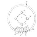
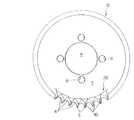
(1) 図9に示すスプロケット1Aのように、外周端から貫通孔6に至る部分に波形部2Aを形成してもよいし、図10に示すスプロケット1Bのように、外周近傍部にのみに波形部2Bを形成してもよい。
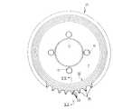
(2) スプロケット1Bにおいて取付部7に、図11、図12に示すように、4つや8つの円形の軽減孔20を形成したり、図13に示すように、小判形の4つの軽減孔21を形成したり、或いは図14に示すように、貫通孔6から延びる切り抜き状の4つの軽減孔22を形成したり、その他の種々の形状の軽減孔を任意の個数形成して、スプロケット1Bの重量を一層軽減させるようにしてもよい。また、図示していないが、スプロケット1においては、歯5の強度を低下させないように、波形部2だけ或いは波形部2と取付部7とに亙って、またスプロケット1Aにおいては、波形部2Aに円形や小判形や切り抜き状或いはその他の種々の形状の軽減孔を形成してもよい。
【0021】
(3) スプロケット1の波形部2においては頂部3を放射状に形成したが、図15に示すスプロケット1Cの波形部2Cのように、頂部3Cを半径方向に対して傾斜状に形成してもよい。尚、スプロケット1A、1Bにおいても、スプロケット1Cと同様に頂部を傾斜状に形成することが可能である。また、スプロケット1Bの波形部2Bにおいては頂部3を放射状に形成したが、図16に示すスプロケット1Dの波形部2Dのように、頂部3Dを湾曲状に形成してもよい。尚、スプロケット1、1Aにおいても、スプロケット1Dと同様に頂部3を湾曲状に形成することが可能である。
(4) スプロケット1、1A〜1Dでは頂部3を平坦に形成したが、図17に示す頂部3Eのように、折曲状に形成してもよいし、図18に示す頂部3Fのように、歯が平板状になるように頂部3の付近をも平坦に形成してもよい。また、波形部2、2A〜2Cの波の周期を長くして、傾斜部4の途中部の外端部にも歯を形成するようにしてもよい。更に、図18のように構成する場合には、隣接する複数の歯を1組にして波の頂部3Fに形成してもよい。
【0022】
次に、本発明に係るスプロケットの参考技術について図19〜図25を参照しながら説明するが、この参考技術は本発明を構成するものではない。
(1) 図19、図20に示すスプロケット31のように、スプロケット31の少なくとも外周部に、半径方向に一定周期で厚さ方向に振幅する環状の波形部32を形成し、波形部32の外周部に歯35を形成してもよい。このスプロケット31においては、図21に示すように、歯35に形成される波形部32の隣接する2つの頂部33を対向するローラリンクプレート12間に位置させることで、スプロケット31とチェーン10との噛合関係が適正状態に維持されることになる。尚、波形部32の形成範囲は、スプロケット31の外縁部を含む範囲であれば任意に設定することが可能である。
【0023】
(2) 図22、図23に示すスプロケット41のように、スプロケット41の少なくとも外周部に厚肉部42と薄肉部43とを円周方向に一定間隔おきに交互に配置した波形部46を形成し、厚肉部42の外端部に歯45を形成してもよい。このスプロケット41におていは、図24に示すように、スプロケット41の厚肉部42に形成した歯45が、通常のスプロケットの歯と同様にチェーン10のローラ11の略全長に亙って噛合することで、スプロケット41とチェーン10との噛合関係が適正状態に維持される。尚、図25に示すように、波形部として波形状の薄肉部43Aを有する波形部46Aを形成してもよい。このスプロケット41においても、スプロケット1C、1Dと同様に、波形部46Aの厚肉部42を半径方向に対して傾斜状や湾曲状に形成してもよい。また、波形部46Aの形成範囲は、スプロケット41の外縁部を含む範囲であれば任意に設定することが可能である。
【0024】
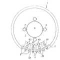
尚、上記各実施例のスプロケットに、チェーンとの接触により発生するノイズを低減するためのノイズ低減手段を設けるようにしてもよい。例えば、図1に示したスプロケット1の周辺に、図26に示すように、可撓性且つ弾性を有する合成ゴムや合成樹脂などのエラストマーからなる環状の緩衝材50を配置してもよい。この場合、緩衝材50は、スプロケット1の複数の歯5に交互に係合させて、スプロケット1の外周部に沿って配置させ、接着剤によってスプロケット1に固定することになる。このように歯底4a付近に緩衝材50を配置したので、チェーンとスプロケットとの噛み合い時にチェーンのローラ11が緩衝材50に当たって、スプロケット1とチェーンとの接触により発生するノイズが低減される。
【0025】
図26に示した例では、緩衝材50を周方向の各部において一様な断面形状に形成したが、図27に示すように、緩衝材50のうち歯5と接触する部分に、歯5に嵌合する凹部52を形成してもよい。このように凹部52を形成すると、緩衝材50をほとんど撓ませることなくスプロケット1の外周部に配置できるので、緩衝材50の耐久性を向上させる上で好ましい。更に、凹部52を歯5の基端部に隙間なく嵌合させれば、スプロケット1と緩衝材50間への異物の侵入等を防止できる。また、環状に形成した緩衝材50を、波形に形成した歯5に合わせて波形に形成することによっても、歯5との間に隙間を形成することなく該緩衝材50をスプロケット1に取り付けることがでる。
【0026】
図26及び図27では緩衝材50を環状に形成した例を示したが、図28に示すように、スプロケット1の歯底4aに緩衝材54を夫々個別に取り付けてもよい。また、緩衝材54を波形部2の溝2a側へ延ばして、スプロケット1と緩衝材54との結合強度を高めるようにしてもよい。
【0027】
図26〜図28で示した緩衝材50、54は、チェーンに接触するように配置されているので、チェーンの駆動時におけるノイズを効果的に低減できるが、緩衝材50、54の耐久性の低下が問題になることがあるので、次のように構成してもよい。
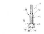
即ち、図29、図30に示すように、スプロケット1の波形部2の各波の溝2aに緩衝材60を充填状に設け、この緩衝材60を少なくともチェーン10と接触しないように接近配置してもよい。この場合、緩衝材60は接着剤のみによりスプロケット1に固定することも可能であるが、図30に示すように、波形部2の各頂部3に挿通孔61を形成し、この挿通孔61にも緩衝材60を充填させて連結部62を形成し、連結部62を介してスプロケット1の表裏両面に配置される緩衝材60を連結させ、緩衝材60をスプロケット1に固定してもよい。また、緩衝材60が波形部2の頂部3よりも厚さ方向の外方側へ突出しないようにする場合には、傾斜部4に挿通孔を形成して、表裏の緩衝材60を連結固定してもよい。
【0028】
また、図31、図32に示すように、緩衝材60の外縁を歯5の外縁と同じ位置或いは歯5の外縁よりもやや内側の位置まで配置させてもよい。但し、緩衝材60は、少なくともチェーン10と噛合する位置において、波形部2の頂部3よりも厚さ方向の外方へ突出しないように構成することになる。このように構成すると、緩衝材60がチェーン10に接触することを回避しつつ緩衝材60をノイズの発生源付近に配置させることが可能となるので、緩衝材60の耐久性を確保しつつ、ノイズを一層効果的に防止できる。
尚、全ての溝2aに緩衝材60を充填状に設けたが、一部の溝2a、例えば1乃至2個おきの溝2aに緩衝材60を設けてもよい。また、スプロケットの一方の面側にのみ緩衝材60を設けてもよい。更に、図7に示すスプロケット1Bのように、波形部2をスプロケット1Bの外周部のみに形成する場合には、緩衝材60を取付部7側へ延ばして、取付部7に形成した挿通孔を介して表裏の緩衝材60を連結してもよい。更にまた、このような構成のノイズ低減手段は、前述した各実施例のスプロケットの対しても同様に設けることが可能である。
【0029】
【発明の効果】
請求項1に係るスプロケットによれば、スプロケットの少なくとも外周部に波形部を形成し、波形部の波の頂部の外端部に歯を形成するという、プレス成形や鋳造により容易に製作可能な簡単な構成で、スプロケットとチェーンとの噛合関係を適正に維持しつつ、スプロケットをチェーンの強度に応じた厚さに構成してその重量を容易に軽減することが可能となる。また、スプロケットの少なくとも外周部に波形部を形成することで、スプロケット全体の捩じれに対する強度、剛性を十分に確保することが可能となる。しかも、波形部が空気を切ることによりスプロケットが効率的に冷却されるので、スプロケットの熱変形も防止できる。更に、スプロケットに付着した泥水等が、スプロケットとチェーン間に噛み込まれることなく円滑に外部に排出されるので、スプロケットやチェーンの破損を未然に防止することが可能となる。更にまた、奇数歯のスプロケットを作製することが可能となる。
【0030】
請求項2乃至3記載のように構成すると、波形部自体がスプロケットの外観を特徴付けるデザインとして作用し、スプロケットの外観が向上する。
請求項5記載のように構成すると、スプロケット全体に占める波形部の面積が大きくなり、波形部の外観を一層強調できる。また、請求項6記載のように構成すると、スプロケットの回転時における空気抵抗を極力少なくすることが可能となる。
請求項10乃至12に記載のように構成すると、軽減孔によりスプロケットの重量を一層低減することが可能となる。また、軽減孔として円形や小判形の軽減孔を一定の規則で形成すると、軽減孔自体がスプロケットの外観を特徴付けるデザインとして作用し、スプロケットの外観が向上する。
請求項13乃至22記載のように構成すると、ノイズ低減手段によりスプロケットとチェーンとの接触により発生するノイズを低減して、チェーン駆動時における静粛性を高めることが可能となる。
【0031】
請求項16記載のように構成すると、ノイズ低減手段をスプロケットに噛合するチェーンに極力接近配置させることが可能で、チェーン駆動時におけるノイズを効率的に低減できる。
請求項17乃至18記載のように構成すると、波形部の溝を活用してスプロケットに対するノイズ低減手段の結合強度を向上できる。
請求項22記載のように構成すると、環状のエラストマーをスプロケットの複数の歯に交互に係止させることで、スプロケットに対してノイズ低減手段を効率良く組付けることが可能となる。
【図面の簡単な説明】
【図1】 本発明のスプロケットの正面図
【図2】 同スプロケットの歯の展開図
【図3】 図1のIII-III 線断面図
【図4】 図1のIV−IV線断面図
【図5】 チェーンとの噛合状態を示す説明図
【図6】 他の実施例に係るスプロケットの正面図
【図7】 図6に示す波形部の歯の展開図
【図8】 図6に示す波形部の図3相当図
【図9】 他の実施例に係るスプロケットの正面図
【図10】 他の実施例に係るスプロケットの正面図
【図11】 他の実施例に係るスプロケットの正面図
【図12】 他の実施例に係るスプロケットの正面図
【図13】 他の実施例に係るスプロケットの正面図
【図14】 他の実施例に係るスプロケットの正面図
【図15】 他の実施例に係るスプロケットの正面図
【図16】 他の実施例に係るスプロケットの正面図
【図17】 他の実施例に係るスプロケットの図3相当図
【図18】 他の実施例に係るスプロケットの図3相当図
【図19】 参考技術に係るスプロケットの正面図
【図20】 図19のXX-XX線断面図
【図21】 同スプロケットのチェーンとの噛合関係を示す説明図
【図22】 参考技術に係るスプロケットの正面図
【図23】 同スプロケットの図3相当図
【図24】 同スプロケットのチェーンとの噛合関係を示す説明図
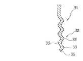
【図25】 参考技術に係るスプロケットの図3相当図
【図26】 ノイズ低減手段を組付けたスプロケットの正面図
【図27】 他の構成のノイズ低減手段を組付けたスプロケットの側面図
【図28】 他の構成のノイズ低減手段を組付けたスプロケットの正面図
【図29】 他の構成のノイズ低減手段を組付けたスプロケットの正面図
【図30】 同ノイズ低減手段を組付けたスプロケットの縦断面図
【図31】 他の構成のノイズ低減手段を組付けたスプロケットの正面図
【図32】 同ノイズ低減手段を組付けたスプロケットの縦断面図
【符号の説明】
1 スプロケット 2 波形部
2a 溝 3 頂部
3a 歯先 4 傾斜部
4a 歯底 4G 傾斜部
5 歯 5a 面取り部
5G 歯 6 貫通孔
7 取付部 8 取付孔
10 チェーン 11 ローラ
12 ローラリンクプレート
13 ピンリンクプレート
1A スプロケット 2A 波形部
1B スプロケット 2B 波形部
20 軽減孔 21 軽減孔
22 軽減孔
1C スプロケット 2C 波形部
3C 頂部
1D スプロケット 2D 波形部
3D 頂部
3E 頂部 3F 頂部
31 スプロケット 32 波形部
33 頂部 35 歯
41 スプロケット 42 厚肉部
43 薄肉部 45 歯
46 波形部 46A 波形部
43A 薄肉部
50 緩衝材 52 凹部
54 緩衝材
60 緩衝材 61 挿通孔
62 連結部[0001]
BACKGROUND OF THE INVENTION
The present invention relates to a sprocket for a winding transmission device that transmits power and the like via a chain.
[0002]
[Prior art]
Generally, a winding transmission device using a chain and a sprocket is widely used in a power transmission system of a motorcycle, a bicycle, or various industrial machines. The shape and size of the chain and sprocket are defined in JIS standards JISB1801 and JISB1802, respectively.
In the sprocket, in order to reduce the production cost by reducing the amount of material used, and in the case of motorcycles, etc., a plurality of elements are arranged in a predetermined arrangement in order to reduce the weight of the vehicle body and improve the responsiveness during acceleration. Some of the sprockets reduce the weight of the sprocket. In addition, the sprocket provided on the rear wheel side of a motorcycle is often exposed to the outside, and the appearance of the motorcycle is greatly influenced by the shape of the mitigation hole, so many proposals have been made regarding the shape and size of the mitigation hole. Yes.
[0003]
[Problems to be solved by the invention]
By providing the reduction holes as described above, the weight of the sprocket can be considerably reduced. However, in order to ensure the strength and rigidity of the teeth, the reduction holes cannot be formed at the outer peripheral edge of the sprocket. Weight reduction was difficult. Moreover, in order to improve the responsiveness at the time of acceleration, it is preferable that the outer peripheral portion of the sprocket is configured to be lightweight. However, as described above, the outer peripheral portion of the sprocket cannot be configured to be sufficiently lightweight with the reduction hole. There is also.
[0004]
On the other hand, the chain has a structure in which two pin link plates and roller link plates arranged in parallel are alternately arranged and mechanically pin-coupled to each other. There is a limit, and if a narrower one than that currently used is used, a problem occurs in strength. On the other hand, sprockets do not have mechanical connections like chains, and in recent years, various materials with excellent strength and rigidity have been proposed. Strength and rigidity can be obtained.
[0005]
Therefore, it is conceivable to use a chain of the current size that has sufficient strength, and to reduce the overall weight by configuring only the sprocket to be thin, but the thickness of the sprocket is between the sprocket and the chain. There is a concern about the occurrence of problems such as backlash in the direction, which causes a problem that the meshing is not smooth and causes noise, the sprocket and the chain are unevenly worn, and the sprocket and the chain are twisted due to the uneven load.
[0006]
The purpose of the present invention is to reduce the weight by maintaining the smooth meshing relationship with the chain, making it possible to reduce the weight of the plate as a whole, and to ensure sufficient strength against twisting and to produce easily by press molding. It is possible to provide a sprocket with a good design.
[0007]
[Means for Solving the Problems]
The sprocket according to
[0008]
Here, the corrugated portion of the sprocket according to
The formation position of the corrugated portion in the sprocket may be formed from the through hole formed in the central portion of the sprocket to the outer peripheral portion as described in
The corrugated portion may be formed such that the top of each wave is flat as described in
As described in
[0009]
The noise reduction means is defined in
As a method of fixing the noise reduction means to the sprocket, claim 20 Fixed with an adhesive as described, or claim 21 As described, an insertion hole is formed in the corrugated portion of the sprocket and fixed through the insertion hole, or a fixing method using both an adhesive and the insertion hole is conceivable.
[0010]
[Action]
In the sprocket according to
Further, the pitch between the tops of at least one wave of the corrugated part is set to a pitch different from the pitch between the tops of the other waves. It is possible to produce sprockets with odd teeth by forming teeth and setting the number of waves with different pitches to odd numbers.
[0011]
When the wave top of the corrugated portion is formed radially, inclined or curved with respect to the radial direction of the sprocket as in
In addition, when the corrugated portion is formed from the through hole in the central portion of the sprocket to the outer peripheral portion as described in
[0012]
[0013]
[0014]
The noise reduction means is claimed in
[0015]
DETAILED DESCRIPTION OF THE INVENTION
Embodiments of the present invention will be described below with reference to the drawings.
The
In the range of about 1/3 of the radius from the outer end of the
[0016]
As shown in FIGS. 6 to 8, the
[0017]
If the plate thickness T1 of the
[0018]
A through
The center of the amplitude of the
[0019]
Next, the operation and effect of the
As shown in FIG. 5, the
Thus, even if the thickness of the
[0020]
Next, another embodiment in which the configuration of the
(1) The corrugated
(2) In the
[0021]
(3) In the
(4) In
[0022]
Next, the reference technology of the sprocket according to the present invention will be described with reference to FIGS. 19 to 25, but this reference technology does not constitute the present invention.
(1) Like the
[0023]
(2) Like the
[0024]
In addition, you may make it provide the noise reduction means for reducing the noise which generate | occur | produces in the sprocket of said each Example by contact with a chain. For example, as shown in FIG. 26, an
[0025]
In the example shown in FIG. 26, the cushioning
[0026]
26 and 27 show an example in which the
[0027]
Since the
That is, as shown in FIG. 29 and FIG. 30, a
[0028]
Further, as shown in FIGS. 31 and 32, the outer edge of the
Although the
[0029]
【The invention's effect】
According to the sprocket of the first aspect, the corrugated portion is formed at least on the outer peripheral portion of the sprocket, and the teeth are formed on the outer end portion of the wave top of the corrugated portion, which can be easily manufactured by press molding or casting. With such a configuration, it is possible to easily reduce the weight of the sprocket by configuring the sprocket to have a thickness corresponding to the strength of the chain while properly maintaining the meshing relationship between the sprocket and the chain. In addition, by forming the corrugated portion at least on the outer peripheral portion of the sprocket, it is possible to sufficiently ensure the strength and rigidity against torsion of the entire sprocket. In addition, since the sprocket is efficiently cooled by cutting the air by the corrugated portion, thermal deformation of the sprocket can also be prevented. Furthermore, since muddy water or the like adhering to the sprocket is smoothly discharged outside without being caught between the sprocket and the chain, it is possible to prevent the sprocket and the chain from being damaged. Furthermore, it becomes possible to produce odd-numbered sprockets.
[0030]
If comprised as described in
If comprised as described in
[0031]
[Brief description of the drawings]
FIG. 1 is a front view of a sprocket of the present invention.
[Fig.2] Development of sprocket teeth
3 is a cross-sectional view taken along line III-III in FIG.
4 is a cross-sectional view taken along line IV-IV in FIG.
FIG. 5 is an explanatory diagram showing a state of meshing with a chain
FIG. 6 is a front view of a sprocket according to another embodiment.
7 is a development view of the teeth of the corrugated portion shown in FIG.
8 is a view corresponding to FIG. 3 of the waveform portion shown in FIG.
FIG. 9 is a front view of a sprocket according to another embodiment.
FIG. 10 is a front view of a sprocket according to another embodiment.
FIG. 11 is a front view of a sprocket according to another embodiment.
FIG. 12 is a front view of a sprocket according to another embodiment.
FIG. 13 is a front view of a sprocket according to another embodiment.
FIG. 14 is a front view of a sprocket according to another embodiment.
FIG. 15 is a front view of a sprocket according to another embodiment.
FIG. 16 is a front view of a sprocket according to another embodiment.
FIG. 17 is a view corresponding to FIG. 3 of a sprocket according to another embodiment.
FIG. 18 is a view equivalent to FIG. 3 of a sprocket according to another embodiment.
FIG. 19 is a front view of a sprocket according to a reference technology.
20 is a sectional view taken along line XX-XX in FIG.
FIG. 21 is an explanatory view showing the meshing relationship with the chain of the sprocket.
FIG. 22 is a front view of a sprocket according to a reference technology.
FIG. 23 is a view corresponding to FIG. 3 of the sprocket.
FIG. 24 is an explanatory view showing the meshing relationship with the chain of the sprocket.
FIG. 25 is a view equivalent to FIG. 3 of the sprocket according to the reference technology.
FIG. 26 is a front view of a sprocket assembled with noise reduction means.
FIG. 27 is a side view of a sprocket assembled with noise reduction means of another configuration.
FIG. 28 is a front view of a sprocket assembled with noise reduction means of another configuration.
FIG. 29 is a front view of a sprocket assembled with noise reduction means of another configuration.
FIG. 30 is a longitudinal sectional view of a sprocket assembled with the noise reduction means.
FIG. 31 is a front view of a sprocket assembled with noise reduction means of another configuration.
FIG. 32 is a longitudinal sectional view of a sprocket assembled with the noise reduction means.
[Explanation of symbols]
1
5
7 Mounting
10
12 Roller link plate
13 pin link plate
20
22 Reduction holes
1C Sprocket 2C Waveform part
3C top
3D top
31
33 top 35 teeth
41
43
46 Waveform part 46A Waveform part
43A Thin section
50
54 cushioning material
60
62 Connecting part
Claims (22)
Translated fromJapanese少なくとも外周部に円周方向に沿って厚さ方向に振幅する波形部を形成するとともに、波形部の波の少なくとも頂部の外端部に歯を形成することで、歯の見かけ上の厚さを適正歯と同じ厚さに設定し、
波形部の少なくとも1つの波における頂部間を他の波における頂部間のピッチと異なるピッチに設定し、この波においては頂部の外端部及び頂部間の傾斜部の途中部の外端部に歯を形成したスプロケット。It consists of a metal plate that is set to 4/5 to 1/10 of the thickness of the base of the appropriate tooth that meshes properly with the chain,
By forming a corrugated portion that swings in the thickness direction along the circumferential direction at least on the outer peripheral portion, and forming a tooth on at least the outer end portion of the wave of the corrugated portion, the apparent thickness of the tooth can be reduced. Set to the same thickness as the proper teeth,
The pitch between the tops of at least one wave of the corrugated part is set to a pitch different from the pitch between the tops of the other waves, and in this wave, teeth are formed at the outer end part of the top part and the middle part of the inclined part between the top parts. Formed sprocket.
Priority Applications (1)
| Application Number | Priority Date | Filing Date | Title |
|---|---|---|---|
| JP2000374519AJP4061836B2 (en) | 1996-08-14 | 2000-12-08 | sprocket |
Applications Claiming Priority (3)
| Application Number | Priority Date | Filing Date | Title |
|---|---|---|---|
| JP8-214529 | 1996-08-14 | ||
| JP21452996 | 1996-08-14 | ||
| JP2000374519AJP4061836B2 (en) | 1996-08-14 | 2000-12-08 | sprocket |
Related Parent Applications (1)
| Application Number | Title | Priority Date | Filing Date |
|---|---|---|---|
| JP21644397ADivisionJP3504466B2 (en) | 1996-08-14 | 1997-08-11 | sprocket |
Publications (2)
| Publication Number | Publication Date |
|---|---|
| JP2001187957A JP2001187957A (en) | 2001-07-10 |
| JP4061836B2true JP4061836B2 (en) | 2008-03-19 |
Family
ID=26520371
Family Applications (1)
| Application Number | Title | Priority Date | Filing Date |
|---|---|---|---|
| JP2000374519AExpired - LifetimeJP4061836B2 (en) | 1996-08-14 | 2000-12-08 | sprocket |
Country Status (1)
| Country | Link |
|---|---|
| JP (1) | JP4061836B2 (en) |
Families Citing this family (14)
| Publication number | Priority date | Publication date | Assignee | Title |
|---|---|---|---|---|
| US9062758B2 (en) | 2011-12-06 | 2015-06-23 | Sram, Llc | Chainring |
| US9182027B2 (en) | 2011-12-06 | 2015-11-10 | Sram, Llc | Chainring |
| DE102013009492B4 (en) | 2013-06-05 | 2023-10-19 | Sram Deutschland Gmbh | Chain ring |
| US9581230B2 (en) | 2014-02-10 | 2017-02-28 | Wolf Tooth Components, LLC | Sprocket |
| US9394986B2 (en) | 2014-02-10 | 2016-07-19 | Wolf Tooth Components, LLC | Sprocket |
| US9394987B2 (en) | 2014-02-10 | 2016-07-19 | Wolf Tooth Components, LLC | Sprocket |
| US9581229B2 (en) | 2014-02-10 | 2017-02-28 | Wolf Tooth Components, LLC | Sprocket |
| US9669899B2 (en) | 2014-02-27 | 2017-06-06 | Eko Sport, Inc. | Alternating tooth chain ring |
| US9404565B2 (en) | 2014-04-08 | 2016-08-02 | Wolf Tooth Components, LLC | Sprocket |
| US9625027B2 (en) | 2014-04-08 | 2017-04-18 | Wolf Tooth Components, LLC | Sprocket |
| US9581231B2 (en) | 2014-04-08 | 2017-02-28 | Wolf Tooth Components, LLC | Sprocket |
| EP3283792B1 (en) | 2015-04-13 | 2024-12-25 | Eko Sport, Inc. | Chain ring with teeth oppositely laterally engaging a drive chain |
| DE102015008662A1 (en) | 2015-07-03 | 2017-01-05 | Sram Deutschland Gmbh | Single sprocket for a bicycle forward crank assembly |
| US10703441B2 (en) | 2015-07-03 | 2020-07-07 | Sram Deutschland Gmbh | Drive arrangement for a bicycle |
- 2000
- 2000-12-08JPJP2000374519Apatent/JP4061836B2/ennot_activeExpired - Lifetime
Also Published As
| Publication number | Publication date |
|---|---|
| JP2001187957A (en) | 2001-07-10 |
Similar Documents
| Publication | Publication Date | Title |
|---|---|---|
| JP4061836B2 (en) | sprocket | |
| US4332574A (en) | Motorcycle sprocket | |
| US7094170B2 (en) | Cushioned sprocket and improved inverted tooth chain for use with same | |
| EP0918962B1 (en) | Sprocket | |
| JP5936195B2 (en) | Wave gear device and flexible external gear | |
| EP1240068B1 (en) | Reduced sound transmitting sprocket for track-type machines | |
| KR102133443B1 (en) | Harmonic reducer | |
| JP4980405B2 (en) | Toothed belt pulley | |
| JPH08166050A (en) | Planetary gear device | |
| JP3504466B2 (en) | sprocket | |
| KR102762772B1 (en) | Sprocket and drive mechanism | |
| US4392542A (en) | Device for preventing displacement of an engine in a motorcycle | |
| JPH112312A (en) | Low noise vibration sprocket | |
| CN2906217Y (en) | Vibration damping chain wheel | |
| JP2001153187A (en) | Guide plate for silent chain | |
| EP0426678A1 (en) | DEVICE FOR SUPPRESSING CRACKS IN A GEARBOX. | |
| KR20090099202A (en) | Harmonic reducer | |
| JP2001200914A (en) | Sprocket | |
| KR20000064855A (en) | Car Drive Plates | |
| JP2001200913A (en) | Sprocket | |
| WO2014192339A1 (en) | Chain driving sprocket | |
| JPS63214566A (en) | Sprocket | |
| JP2005069401A (en) | Helical gear | |
| EP1059469A1 (en) | Sprocket | |
| JP3912957B2 (en) | Vehicle shaft coupling |
Legal Events
| Date | Code | Title | Description |
|---|---|---|---|
| A621 | Written request for application examination | Free format text:JAPANESE INTERMEDIATE CODE: A621 Effective date:20040720 | |
| A711 | Notification of change in applicant | Free format text:JAPANESE INTERMEDIATE CODE: A711 Effective date:20040901 | |
| A711 | Notification of change in applicant | Free format text:JAPANESE INTERMEDIATE CODE: A711 Effective date:20050624 | |
| A131 | Notification of reasons for refusal | Free format text:JAPANESE INTERMEDIATE CODE: A132 Effective date:20070724 | |
| A521 | Written amendment | Free format text:JAPANESE INTERMEDIATE CODE: A523 Effective date:20070907 | |
| A521 | Written amendment | Free format text:JAPANESE INTERMEDIATE CODE: A523 Effective date:20070907 | |
| TRDD | Decision of grant or rejection written | ||
| A01 | Written decision to grant a patent or to grant a registration (utility model) | Free format text:JAPANESE INTERMEDIATE CODE: A01 Effective date:20071204 | |
| A61 | First payment of annual fees (during grant procedure) | Free format text:JAPANESE INTERMEDIATE CODE: A61 Effective date:20071217 | |
| R150 | Certificate of patent or registration of utility model | Free format text:JAPANESE INTERMEDIATE CODE: R150 | |
| FPAY | Renewal fee payment (event date is renewal date of database) | Free format text:PAYMENT UNTIL: 20110111 Year of fee payment:3 | |
| FPAY | Renewal fee payment (event date is renewal date of database) | Free format text:PAYMENT UNTIL: 20110111 Year of fee payment:3 | |
| FPAY | Renewal fee payment (event date is renewal date of database) | Free format text:PAYMENT UNTIL: 20110111 Year of fee payment:3 | |
| FPAY | Renewal fee payment (event date is renewal date of database) | Free format text:PAYMENT UNTIL: 20120111 Year of fee payment:4 | |
| FPAY | Renewal fee payment (event date is renewal date of database) | Free format text:PAYMENT UNTIL: 20120111 Year of fee payment:4 | |
| FPAY | Renewal fee payment (event date is renewal date of database) | Free format text:PAYMENT UNTIL: 20130111 Year of fee payment:5 | |
| FPAY | Renewal fee payment (event date is renewal date of database) | Free format text:PAYMENT UNTIL: 20130111 Year of fee payment:5 | |
| FPAY | Renewal fee payment (event date is renewal date of database) | Free format text:PAYMENT UNTIL: 20140111 Year of fee payment:6 | |
| R250 | Receipt of annual fees | Free format text:JAPANESE INTERMEDIATE CODE: R250 | |
| R250 | Receipt of annual fees | Free format text:JAPANESE INTERMEDIATE CODE: R250 | |
| R250 | Receipt of annual fees | Free format text:JAPANESE INTERMEDIATE CODE: R250 | |
| R250 | Receipt of annual fees | Free format text:JAPANESE INTERMEDIATE CODE: R250 | |
| EXPY | Cancellation because of completion of term |