JP4061105B2 - Haptic device - Google Patents
Haptic deviceDownload PDFInfo
- Publication number
- JP4061105B2 JP4061105B2JP2002097595AJP2002097595AJP4061105B2JP 4061105 B2JP4061105 B2JP 4061105B2JP 2002097595 AJP2002097595 AJP 2002097595AJP 2002097595 AJP2002097595 AJP 2002097595AJP 4061105 B2JP4061105 B2JP 4061105B2
- Authority
- JP
- Japan
- Prior art keywords
- force
- unit
- pattern
- patterns
- degrees
- Prior art date
- Legal status (The legal status is an assumption and is not a legal conclusion. Google has not performed a legal analysis and makes no representation as to the accuracy of the status listed.)
- Expired - Fee Related
Links
Images


Classifications
- G—PHYSICS
- G06—COMPUTING OR CALCULATING; COUNTING
- G06F—ELECTRIC DIGITAL DATA PROCESSING
- G06F3/00—Input arrangements for transferring data to be processed into a form capable of being handled by the computer; Output arrangements for transferring data from processing unit to output unit, e.g. interface arrangements
- G06F3/01—Input arrangements or combined input and output arrangements for interaction between user and computer
- G06F3/016—Input arrangements with force or tactile feedback as computer generated output to the user
- G—PHYSICS
- G06—COMPUTING OR CALCULATING; COUNTING
- G06F—ELECTRIC DIGITAL DATA PROCESSING
- G06F3/00—Input arrangements for transferring data to be processed into a form capable of being handled by the computer; Output arrangements for transferring data from processing unit to output unit, e.g. interface arrangements
- G06F3/01—Input arrangements or combined input and output arrangements for interaction between user and computer
- G06F3/03—Arrangements for converting the position or the displacement of a member into a coded form
- G06F3/033—Pointing devices displaced or positioned by the user, e.g. mice, trackballs, pens or joysticks; Accessories therefor
- G06F3/0338—Pointing devices displaced or positioned by the user, e.g. mice, trackballs, pens or joysticks; Accessories therefor with detection of limited linear or angular displacement of an operating part of the device from a neutral position, e.g. isotonic or isometric joysticks
Landscapes
- Engineering & Computer Science (AREA)
- General Engineering & Computer Science (AREA)
- Theoretical Computer Science (AREA)
- Human Computer Interaction (AREA)
- Physics & Mathematics (AREA)
- General Physics & Mathematics (AREA)
- Mechanical Control Devices (AREA)
- Rotary Switch, Piano Key Switch, And Lever Switch (AREA)
- User Interface Of Digital Computer (AREA)
- Switches With Compound Operations (AREA)
Description
Translated fromJapanese【0001】
【発明の属する技術分野】
本発明は、力覚付与装置に関し、特に、操作部に与えられるフォースパターンを、ユニットフォースパターンを準備することにより、これらユニットフォースパターンを組み合わせて作成する力覚付与装置に関する。
【0002】
【従来の技術】
従来の力覚付与装置を図6、7に基づいて説明する。図6は従来の力覚付与装置のブロック図、図7は従来の力覚付与装置のフォースパターンの発生力のグラフをそれぞれ示す。
【0003】
操作部としてのノブ51は、所定の機能を出力するために回転可能に設けられている。
【0004】
位置センサ52は、回転型エンコーダなどであって、ノブ51の回転軸(図示せず)に取り付けられ、ノブ51の回転角度位置を検出するようになっている。
【0005】
アクチュエータ54は、電磁コイルやモータなどノブ51に発生力を与えるものである。
【0006】
制御部53は、図6に示すように、コントローラ53aとメモリ(ROM)53bから構成され、メモリ53bは、各回転角度位置に応じて、発生力をアクチュエータ54よりノブ51へ加える各種フォースパターンのテーブル(パターン1〜パターンN)を備え、コントローラ53aは位置センサ52からノブ51の回転角度位置の信号を受け、指定されたテーブルに記憶された回転角度位置に応じた発生力の出力の指示をアクチュエータ54に出している。各種フォースパターンの各テーブルには、フォースパターンの種類(パターン1〜パターンN)によりノブ51の回転角度位置(位置1〜位置n)に対応して発生力(発生力1〜発生力n)が記憶されている。
【0007】
各テーブル(パターン1,パターン2,パターン3;図6参照)の発生力と回転角度の関係は、図7A〜Cのグラフに示すようになっている。図7Aに示すパターン1のフォースパターンは、ノブ51の1回転360度中、80度、120度、160度、360度の各回転角度でグラフの線の傾きが変わりクリック感触を持つ。図7Bに示すパターン2のフォースパターンは、ノブ51の1回転360度中、同じパターンを3回繰り返し、80度、120度、200度、240度、320度、360度の各回転角度でグラフの線の傾きが変わりクリック感触を持つ。図7Cに示すパターン3のフォースパターンは、ノブ51の1回転360度中、同じパターンを9回繰り返し、40度おきの各回転角度でグラフの線の傾きが変わりクリック感触を持つ。各フォースパターンは異なる波形になっているためそれぞれの1回転中のクリック感触は異なる。
【0008】
従来の力覚付与装置の動作を説明する。ノブ51を回転させると、ノブ51の回転軸に取り付けられている回転角度の位置センサ52がノブ51の回転角度を検出する。検出された回転角度の信号は制御部53に送られ、回転角度の信号を受け取った制御部53は、メモリ53bに記憶されている回転角度位置に対応する発生力のテーブル(パターン1、パターン2、・・・・パターンN)の内から指定されたテーブルを読み出して、コントローラ53aが回転角度位置に対応する発生力を出力するようにアクチュエータ54に指示を出す。アクチュエータ54はコントローラ53aから指示された発生力をノブ51に出力するように動作する。ノブ51はアクチュエータ54の発生力を受けて所定の操作感触を出力する。
【0009】
【発明が解決しようとする課題】
しかしながら、上記した従来の力覚付与装置においては、フォースパターンの種類が増えると、必要とするメモリ量が増加し、必要なメモリ量を準備するのが困難になるという問題があった。
【0010】
従って、本発明の目的は、フォースパターンの種類が増えても必要とするメモリ量が少ない力覚付与装置を提供することにある。
【0011】
【課題を解決するための手段】
本発明の力覚付与装置は、操作部と、操作部に感触(力覚)を与えるアクチュエータと、このアクチュエータを制御する制御部とを備え、前記制御部は、フォースパターンの異なる複数のユニットフォースパターン、および、パターンの異なる複数の並べ方のパターンを記憶して、前記並べ方のパターンに従って前記ユニットフォースパターンを並べて合成フォースパターンを形成すると共に、この合成フォースパターンにより前記アクチュエータを制御して、前記操作部に感触を与える。
この構成により、ユニットフォースパターンを組み合わせるので、数の少ないユニットフォースパターンを記憶するメモリと、ユニットフォースパターンを組み合わせるときの並べ方を記憶するメモリがあればよいので、フォースパターンの種類が増えても全体として必要なメモリ量(ROM容量)が少なくなる。
【0012】
また、前記複数のユニットフォースパターンの内の一つは、所定の値から力が増加した後力が減少する山形状、または所定の値から力が減少した後力が増加する谷形状で、クリック感触を与えるものである。
この構成により、山形状または谷形状のユニットフォースパターンを選ぶだけでよいので、容易にクリック感触を作り出せる。
【0013】
また、前記複数のユニットフォースパターンの内の一つは、所定の値から力が増加する上昇する傾斜を有し、減速感触を与えるものである。
この構成により、所定の値から力が増加する上昇する傾斜を有するユニットフォースパターンを選ぶだけでよいので、容易に減速感触を得ることができる。
【0014】
また、前記複数のユニットフォースパターンの内の一つは、所定の値から力が減少する下降する傾斜を有し、加速感触を与えるものである。
この構成により、所定の値から力が減少する下降する傾斜を有するユニットフォースパターンを選ぶだけでよいので、容易に加速感触を得ることができる。
【0015】
また、前記複数のユニットフォースパターンの内の一つは、所定の値で力が変化しない水平な直線状で、一定の力の感触を与えるものである。
この構成により、所定の値で力が変化しない水平な直線状のユニットフォースパターンを選ぶだけでよいので容易に一定の力の感触を得ることができる。
【0016】
【発明の実施の形態】
本発明の力覚付与装置の実施形態について図1〜図5に基づいて説明する。
図1は本発明の力覚付与装置の実施形態の部分断面図、図2は本発明の力覚付与装置の実施形態のブロック図、図3は本発明の力覚付与装置の実施形態で用いられる合成フォースパターンのグラフ、図4は本発明の力覚付与装置の実施形態で用いられるユニットフォースパターンのグラフ、図5は本発明の力覚付与装置の実施形態のユニットフォースパターンの並べ方を示す図をそれぞれ示す。
【0017】
基台1は、絶縁樹脂製で、中央に孔1aを有する円環状をなしている。
【0018】
プリント配線板2は、力覚付与装置に必要な制御部12などを構成する各種電気部品(図示せず)を搭載し、基台1の下面に取り付けられている。
【0019】
アクチュエータ3は電磁コイルであって、鉄心にコイルを巻回して円環状に配置したもので、中央に円形の孔3aを有し、このアクチュエータ3は基台1の上に設置されている。
【0020】
駆動体4は、絶縁樹脂製で、軸部4a、円板部4b、リング状部4cからなり、円板状の円板部4bの周縁からリング状部4cが上方へ環状に立ち上がっており、円板部4bの中央に軸部4aが円板部4bに対して垂直に形成されている。軸部4aはアクチュエータ3の円形の孔3aに回転可能に嵌合している。
【0021】
アーマチュア5は、鉄板を有し、中央に円形の孔5aを有する円板状の形状をなしている。アーマチュア5は、その一方の面が駆動体4の円板部4bの下面にアーマチュア戻しバネ6を介して取り付けられている。アーマチュア5の他方の面はアクチュエータ3の上面に空間を介して対向している。
【0022】
係合部材7は、絶縁樹脂製で、リング状の側壁7aと底板部7bからなり、円板状の底板部7bの周縁からリング状の側壁7aが立ち上がった開口のある器状をなしている。係合部材7の側壁7aは、駆動体4のリング状部4cを外側から包むように嵌合し、係合部材7と駆動体4とは互いに結合している。
【0023】
操作軸8は、金属製で、係合部7の底板部7bの中央に垂直に取り付け固定されている。操作軸8には太径部8aが形成されている。
【0024】
位置センサ9は、回転角度位置を検出する回転型エンコーダであって、円筒形をなし、回転体と固定体(図示せず)からなり、回転体は操作軸8に取り付け固定され、固定体には突起9aが設けられている。
【0025】
操作部としてのノブ10は、絶縁樹脂からなり、円筒状をなして、中心に軸孔(図示せず)を有している。ノブ10の軸孔には、操作軸8の上端部が嵌合している。
【0026】
パネル板11は、金属板よりなり、表面は塗装されており、孔11aを有している。パネル板11の孔11aには操作軸8が挿通され、パネル板11の表面には操作軸8の太径部8aが当接している。位置センサ9の固定体の突起9aは、パネル板11の図示せぬ孔に嵌合され、位置センサ9の固定体はパネル板11に固定されている。また、位置センサ9は、操作軸8の軸方向で、パネル板11と係合部材7との間に挟まれて位置している。
【0027】
次に、本発明の実施形態の力覚付与装置の動作について説明する。
ノブ10を回転させて操作軸8を回転すると、係合部7を介して駆動体4が回転する。この時、操作軸8は位置センサ9の回転体を回転させ、回転体の回転角の信号をプリント配線板2に搭載された制御部12へ送る。制御部12は第1のメモリ(ROM)12aに記憶されたユニットフォースパターン(ユニット1、ユニット2、ユニット3、・・・)の中から異なるユニットフォースパターンを取り出し、第2のメモリ(ROM)12bからユニットフォースパターンの並べ方のパターン(パターン1、パターン2、パターン3、・・・)の中から指定された並べ方のパターンを選び、選んだ並べ方のパターンに従って、各ユニットフォースパターンを並べて合成フォースパターンを作成し、制御部12のコントローラ12cへ送る。
【0028】
コントローラ12cは合成フォースパターンに応じた電流をアクチュエータ3に送るよう指示を出す。電流を受けたアクチュエータ3は、受けた電流に応じて対向するアーマチュア5を吸引する。アーマチュア5はアクチュエータ3から、アクチュエータ3に与えた電流に応じた吸引力を受けるが、この時アーマチュア戻しバネ6がその厚さ方向に伸びて、アーマチュア5はアクチュエータ3の上面に吸着される。この状態で、ノブ10を回転させようとすると、アーマチュア5がアクチュエータ3に吸着されているので、吸引力に応じた摩擦力が生じて、ノブ10を回転させようとする回転トルクが増加する。このようにして所定の合成フォースパターンに対応した摩擦力(発生力)により、ノブ10に所定の回転トルクが得られるようになっている。
【0029】
アクチュエータ3への通電を止めると、アクチュエータ3がアーマチュア5を吸引する吸引力はなくなるので、アーマチュア戻しバネ6が縮んで、アーマチュア5はアクチュエータ3の上面から離れ、ノブ10はアーマチュア5の摩擦力がない状態で回転する。
【0030】
次に、各種合成フォースパターンとこの合成フォースパターンをユニットフォースパターンから作成する方法について説明する。
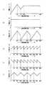
図3には各種合成フォースパターンが示されている。図3Aの合成フォースパターンは、ノブ10の回転角度をゼロから増加させていくと、ノブ10の回転トルクを上げる力(発生力)がゼロから徐々に増加し、80度回転したところで発生力の増加が止まり減少し始める。更にノブ10を回転させると発生力は減少し続け、120度で発生力の減少は止まり増加し始め、更にノブ10を回転させると160度で発生力の増加が止まり、発生力は一定の値になる。この場合、発生力が増加から減少に移る回転角度位置、減少から増加に移る回転角度位置、増加から一定値になる回転角度位置でそれぞれクリック感触が得られる。従って、この場合、1回転360度中、回転角度位置が80度、120度、160度でそれぞれクリック感触が得られることになる。
【0031】
図3Bの合成フォースパターンは、ノブ10に対する発生力が一定で、1回転360度に渡って回転トルクが一定の重さになる。
【0032】
図3Cの合成フォースパターンは、ノブ10の回転角度をゼロから増加させていくと、ノブ10に対する発生力が徐々に増加し、80度回転したところで発生力の増加は止まり減少し始める。更にノブ10を回転させると発生力は減少し続け、120度で減少は止まる。この場合の合成フォースパターンは、1回転360度の中で、120度までの発生力の増減を3回繰り返す。この場合も、発生力の増加から減少に移る回転角度位置、減少から増加に移る回転角度位置において、それぞれノブ10にクリック感触を生ずる。従って、この場合、クリック感触が得られるのは、1回転360度中、80度、120度、200度、240度、320度、360度の回転角度位置で、合計6回ある。
【0033】
図3Dの合成フォースパターンは、ノブ10の回転角度をゼロから増加させていくと、ノブ10のに対する発生力が所定の値から徐々に増加し、40度回転したところで発生力の増加が止まる。この場合の合成フォースパターンは、40度までの発生力の変化状態を1回転360度中9回繰り返す。従って、この場合のクリック感触は1回転360度中、40度間隔で9回現れる。
【0034】
図3Eの合成フォースパターンは、ノブの回転角度をゼロから増加させていくと、ノブ10に対する発生力が所定の値から徐々に減少し、40度回転したところで発生力の減少が止まる。この場合の合成フォースパターンは、40度までの発生力の変化状態を1回転360度中9回繰り返す。従って、この場合のクリック感触も1回転360度中、40度間隔で9回現れる。
【0035】
図3Fの合成フォースパターンは、ノブ10の回転角度をゼロから増加させていくと、ノブ10に対する発生力が所定の値からから徐々に増加し、40度回転したところで発生力が減少し始める。更にノブ10を回転させると発生力は減少し続け、80度で発生力の減少は止まる。この場合の合成フォースパターンは、80度までの発生力の変化状態を1回転360度中4回繰り返し、その後0度−40度の発生力の変化が加わる。この場合は発生力の増減の変化が、1回転360度中9回現れる。従って、この場合のクリック感触も1回転360度中、40度間隔で9回現れる。
【0036】
但し、図3D、図3E、図3Fの合成フォースパターンのクリック感触は、発生のタイミングは同じであるが、感触そのものはフォースパターンの形状が違うためそれぞれ異なる感触となる。従って、図3Aで得られるクリック感触も合成フォースパターンの形状が違うため、図3D、図3E、図3Fで得られるクリック感触とは違った感触になる。また、図3A、図3Cの80度におけるクリック感触はフォースパターンの形状が同じであるため同じ感触になる。
【0037】
上記した各種合成フォースパターンを作成するユニットフォースパターンは図4A〜図4Dに示されている。図4Aに示すユニット1のユニットフォースパターンは、0度−80度の範囲で発生力がゼロから徐々に増加し、その後80度−120度の範囲で発生力が80度の値から徐々に減少し120度において所定の値まで下がる。ユニット1のフォースパターンの場合、80度において発生力が増加から減少に移るため、80度においてノブ10の操作感触はクリック感触となる。
【0038】
図4Bに示すユニット2のユニットフォースパターンは、0度−40度の範囲で発生力が所定の値から増加する上昇する傾斜を有するグラフ形状である。ユニット2のユニットフォースパターンの場合、回転角度の増加に伴って発生力が増加するので、ノブ10の操作感触は減速感触となる。
【0039】
図4Cに示すユニット3のユニットフォースパターンは、0度−40度の範囲で発生力が所定の値から減少する下降する傾斜を有するグラフ形状である。ユニット3のユニットフォースパターンの場合、回転角度の増加に伴って発生力が減少するので、ノブ10の操作感触は加速感触となる。
【0040】
図4Dに示すユニット4のユニットフォースパターンは、0度−40度の範囲で発生力が所定の値から変化せず、水平な直線状のグラフ形状である。ユニット4のユニットフォースパターンの場合、発生力が一定で、ノブ10の回転トルクは一定の重さになる。
【0041】
上記各ユニットフォースパターンは制御部12の第1のメモリ12aに記憶されている。また、各ユニットフォースパターンの並べ方は第2のメモリ12bに記憶されている。図5A〜Fには並べ方のパターンが9個示されている。
合成フォースパターンの種類が多い場合、各ユニットフォースパターン(図4A〜D)を記憶するメモリ量と、ユニットフォースパターンの並べ方(図5A〜F)を記憶するメモリ量の和は、各合成フォースパターン(図3A〜F)をそれぞれ記憶するメモリ量の和より格段に少なくなる。
【0042】
図3Aに示す合成フォースパターンをユニットフォースパターンを用いて作成する場合、ユニットフォースパターンとして、ユニット1,ユニット2,ユニット4を用い、図5Aに示すように、ユニット1とユニット2を各1個並べた後にユニット4を5個並べる。
【0043】
図3Bに示す合成フォースパターンをユニットフォースパターンを用いて作成する場合、ユニットフォースパターンとして、ユニット4を用い、図5Bに示すように、ユニット4を9個並べる。
【0044】
図3Cに示す合成フォースパターンをユニットフォースパターンを用いて作成する場合、ユニットフォースパターンとして、ユニット1を用い、図5Cに示すように、ユニット1を3個並べる。
【0045】
図3Dに示す合成フォースパターンをユニットフォースパターンを用いて作成する場合、ユニットフォースパターンとして、ユニット2を用い、図5Dに示すように、ユニット2を9個並べる。
【0046】
図3Eに示す合成フォースパターンをユニットフォースパターンを用いて作成する場合、ユニットフォースパターンとして、ユニット3を用い、図5Eに示すように、ユニット3を9個並べる。
【0047】
図3Fに示す合成フォースパターンをユニットフォースパターンを用いて作成する場合、ユニットフォースパターンとして、ユニット2,ユニット3を用い、図5Fに示すように、ユニット2とユニット3を各1個並べた組を4組並べ、その後にユニット2を1個並べる。
図3A〜Fに示す合成フォースパターンの図において、回転角度0度は現在のノブ10の位置としてもよいし、所定のある回転位置としてもよい。
以上のようにして、ユニットフォースパターンから合成フォースパターンを作成する。
【0048】
尚、上記した実施形態においては、位置センサが検出する量として1次元である回転角度を採用したが、本発明はこれに限定されることなく、位置センサが検出する量としては操作部の並進する移動量を採用してもよい。
【0049】
また、上記した実施形態の合成フォースパターンは、上記実施形態のユニットフォースパターンの組み合わせに限定されず、様々な組み合わせを取ることができる。
【0050】
また、上記実施形態において、クリック感触を発生するユニットフォースパターンとして山形状のユニットフォースパターンを説明したが、本発明はこれに限定されることなく、クリック感触を得るためには谷形状のユニットフォースパターンを採用してもよい。
【0051】
また、上記実施形態において、アクチュエータ3を電磁コイルとして説明したが、本発明はこれに限定されることなく、アクチュエータ3としてDCモータを使用してもよく、DCモータはノブ10の操作軸8に直接、またはギヤなどを介して間接的に取り付けられ、ノブ10の回転方向と同一回転方向に回転力(発生力)を与えるか、またはノブ10の回転方向と逆方向に回転力を与えるようにしてもよい。
【0052】
【発明の効果】
以上説明したように、本発明の力覚付与装置は、操作部と、操作部に感触を与えるアクチュエータと、このアクチュエータを制御する制御部とを備え、制御部は、フォースパターンの異なる複数のユニットフォースパターンを記憶して、このユニットフォースパターンを組み合わせて合成フォースパターンを形成すると共に、この合成フォースパターンによりアクチュエータを制御して、操作部に感触を与える。
【0053】
上記構成により、ユニットフォースパターンを組み合わせるので、数の少ないユニットフォースパターンを記憶するメモリと、ユニットフォースパターンを組み合わせるときの並べ方を記憶するメモリがあればよいので、フォースパターンの種類が増えても全体として必要なメモリ量(ROM容量)が少なくなる。
【図面の簡単な説明】
【図1】本発明の力覚付与装置の実施形態の部分断面図である。
【図2】本発明の力覚付与装置の実施形態のブロック図である。
【図3】本発明の力覚付与装置の実施形態で用いられる合成フォースパターンのグラフである。
【図4】本発明の力覚付与装置の実施形態で用いられるユニットフォースパターンのグラフである。
【図5】本発明の力覚付与装置の実施形態のユニットフォースパターンの並べ方を示す図である。
【図6】従来の力覚付与装置のブロック図である。
【図7】従来の力覚付与装置のフォースパターンの発生力のグラフである。
【符号の説明】
3 アクチュエータ
9 位置センサ
10 ノブ(操作部)
12 制御部
12a 第1のメモリ
12b 第2のメモリ
12c コントローラ[0001]
BACKGROUND OF THE INVENTION
The present invention relates to a force sense imparting device, and in particular, relates to a force sense imparting device that creates a force pattern given to an operation unit by combining unit force patterns by preparing unit force patterns.
[0002]
[Prior art]
A conventional force sense imparting device will be described with reference to FIGS. FIG. 6 is a block diagram of a conventional force sense imparting device, and FIG. 7 is a graph of force generated in a force pattern of the conventional force sense imparting device.
[0003]
The
[0004]
The
[0005]
The
[0006]
As shown in FIG. 6, the
[0007]
The relationship between the generated force and the rotation angle of each table (
[0008]
The operation of the conventional force sense applying device will be described. When the
[0009]
[Problems to be solved by the invention]
However, the above-described conventional force sense imparting device has a problem that as the number of types of force patterns increases, the amount of memory required increases, making it difficult to prepare the necessary amount of memory.
[0010]
Accordingly, an object of the present invention is to provide a force sense imparting device that requires a small amount of memory even if the types of force patterns increase.
[0011]
[Means for Solving the Problems]
The force sense imparting device of the present invention includes an operation unit, an actuator that gives a touch (force sense) to the operation unit, and a control unit that controls the actuator, and the control unit includes a plurality of unit forces having different force patterns. A patternand a plurality of patterns with different patterns are stored, and the unit force pattern isarrangedaccording to the arrangement pattern to form a combined force pattern, and the actuator is controlled by the combined force pattern to perform the operation. Give a feel to the part.
With this configuration, unit force patterns are combined, so it is only necessary to have a memory that stores a small number of unit force patterns and a memory that stores the arrangement method when unit force patterns are combined. As a result, the required memory amount (ROM capacity) is reduced.
[0012]
In addition, one of the plurality of unit force patterns may have a mountain shape in which the force decreases after the force increases from a predetermined value, or a valley shape in which the force increases after the force decreases from a predetermined value. It gives a touch.
With this configuration, it is only necessary to select a unit force pattern having a mountain shape or a valley shape, so that a click feeling can be easily created.
[0013]
Further, one of the plurality of unit force patterns has a rising slope in which the force increases from a predetermined value, and gives a feeling of deceleration.
With this configuration, it is only necessary to select a unit force pattern having an ascending gradient in which the force increases from a predetermined value, so that a deceleration feel can be easily obtained.
[0014]
Further, one of the plurality of unit force patterns has a descending slope in which the force decreases from a predetermined value, and gives an acceleration feeling.
With this configuration, it is only necessary to select a unit force pattern having a descending slope in which the force decreases from a predetermined value, so that an acceleration feeling can be easily obtained.
[0015]
Further, one of the plurality of unit force patterns is a horizontal straight line in which the force does not change at a predetermined value, and gives a feeling of a constant force.
With this configuration, it is only necessary to select a horizontal linear unit force pattern in which the force does not change at a predetermined value, so that a constant force feel can be easily obtained.
[0016]
DETAILED DESCRIPTION OF THE INVENTION
An embodiment of a force sense imparting device of the present invention will be described with reference to FIGS.
FIG. 1 is a partial cross-sectional view of an embodiment of the haptic device of the present invention, FIG. 2 is a block diagram of the embodiment of the haptic device of the present invention, and FIG. 3 is used in the embodiment of the haptic device of the present invention. FIG. 4 is a graph of unit force patterns used in the embodiment of the force sense imparting device of the present invention, and FIG. 5 shows how unit force patterns are arranged in the embodiment of the force sense imparting device of the present invention. Each figure is shown.
[0017]
The
[0018]
The printed
[0019]
The
[0020]
The
[0021]
The armature 5 has an iron plate and has a disk shape having a
[0022]
The engaging
[0023]
The
[0024]
The
[0025]
The
[0026]
The
[0027]
Next, the operation of the haptic device according to the embodiment of the present invention will be described.
When the
[0028]
The
[0029]
When the energization of the
[0030]
Next, various synthetic force patterns and a method of creating the synthetic force pattern from the unit force pattern will be described.
FIG. 3 shows various synthetic force patterns. In the synthetic force pattern of FIG. 3A, when the rotation angle of the
[0031]
In the synthetic force pattern of FIG. 3B, the generated force on the
[0032]
In the synthetic force pattern of FIG. 3C, when the rotation angle of the
[0033]
In the synthetic force pattern of FIG. 3D, when the rotation angle of the
[0034]
In the synthetic force pattern of FIG. 3E, when the rotation angle of the knob is increased from zero, the generated force with respect to the
[0035]
In the synthetic force pattern of FIG. 3F, when the rotation angle of the
[0036]
However, the click feeling of the synthetic force pattern in FIGS. 3D, 3E, and 3F is generated at the same timing, but the touch itself has a different feel because the shape of the force pattern is different. Therefore, the click feeling obtained in FIG. 3A is also different from the click feeling obtained in FIGS. 3D, 3E, and 3F because the shape of the synthetic force pattern is different. The click feeling at 80 degrees in FIGS. 3A and 3C has the same feeling because the shape of the force pattern is the same.
[0037]
Unit force patterns for creating the above-mentioned various synthetic force patterns are shown in FIGS. 4A to 4D. In the unit force pattern of
[0038]
The unit force pattern of the
[0039]
The unit force pattern of the
[0040]
The unit force pattern of the
[0041]
Each unit force pattern is stored in the
When there are many types of synthetic force patterns, the sum of the memory amount for storing each unit force pattern (FIGS. 4A to 4D) and the memory amount for storing the unit force patterns (FIGS. 5A to 5F) (FIGS. 3A to 3F) are significantly smaller than the sum of the amounts of memory for storing them.
[0042]
When the synthetic force pattern shown in FIG. 3A is created using a unit force pattern,
[0043]
When the synthetic force pattern shown in FIG. 3B is created using a unit force pattern,
[0044]
When the synthetic force pattern shown in FIG. 3C is created using a unit force pattern,
[0045]
When the synthetic force pattern shown in FIG. 3D is created using a unit force pattern,
[0046]
When the synthetic force pattern shown in FIG. 3E is created using a unit force pattern,
[0047]
When the synthetic force pattern shown in FIG. 3F is created by using a unit force pattern,
3A to 3F, the rotation angle of 0 degrees may be the current position of the
As described above, a composite force pattern is created from the unit force pattern.
[0048]
In the above-described embodiment, a one-dimensional rotation angle is adopted as the amount detected by the position sensor. However, the present invention is not limited to this, and the amount detected by the position sensor is the translation of the operation unit. You may employ | adopt the movement amount to perform.
[0049]
Further, the combined force pattern of the above-described embodiment is not limited to the combination of the unit force patterns of the above-described embodiment, and various combinations can be taken.
[0050]
In the above embodiment, a mountain-shaped unit force pattern has been described as a unit force pattern that generates a click feeling. However, the present invention is not limited to this, and in order to obtain a click feeling, a valley-shaped unit force is used. A pattern may be adopted.
[0051]
In the above embodiment, the
[0052]
【The invention's effect】
As described above, the force sense imparting device of the present invention includes an operation unit, an actuator that gives a feeling to the operation unit, and a control unit that controls the actuator, and the control unit includes a plurality of units having different force patterns. A force pattern is stored and a combined force pattern is formed by combining the unit force patterns, and an actuator is controlled by the combined force pattern to give a feeling to the operation unit.
[0053]
With the above configuration, unit force patterns are combined, so it is only necessary to have a memory that stores a small number of unit force patterns and a memory that stores the arrangement method when unit force patterns are combined. As a result, the required memory amount (ROM capacity) is reduced.
[Brief description of the drawings]
FIG. 1 is a partial sectional view of an embodiment of a force sense imparting device of the present invention.
FIG. 2 is a block diagram of an embodiment of a haptic device according to the present invention.
FIG. 3 is a graph of a synthetic force pattern used in the embodiment of the force sense imparting device of the present invention.
FIG. 4 is a graph of a unit force pattern used in the embodiment of the force sense imparting device of the present invention.
FIG. 5 is a diagram showing how unit force patterns are arranged in the embodiment of the force sense imparting device of the present invention.
FIG. 6 is a block diagram of a conventional force sense imparting device.
FIG. 7 is a graph of force generation of a force pattern of a conventional force sense imparting device.
[Explanation of symbols]
3
12
Claims (5)
Translated fromJapanesePriority Applications (4)
| Application Number | Priority Date | Filing Date | Title |
|---|---|---|---|
| JP2002097595AJP4061105B2 (en) | 2002-03-29 | 2002-03-29 | Haptic device |
| EP03006762AEP1349050A3 (en) | 2002-03-29 | 2003-03-25 | Force feedback device |
| KR10-2003-0019189AKR100526157B1 (en) | 2002-03-29 | 2003-03-27 | Apparatus for providing power sensing |
| US10/400,303US7187359B2 (en) | 2002-03-29 | 2003-03-27 | Force feedback device |
Applications Claiming Priority (1)
| Application Number | Priority Date | Filing Date | Title |
|---|---|---|---|
| JP2002097595AJP4061105B2 (en) | 2002-03-29 | 2002-03-29 | Haptic device |
Publications (2)
| Publication Number | Publication Date |
|---|---|
| JP2003295959A JP2003295959A (en) | 2003-10-17 |
| JP4061105B2true JP4061105B2 (en) | 2008-03-12 |
Family
ID=27800580
Family Applications (1)
| Application Number | Title | Priority Date | Filing Date |
|---|---|---|---|
| JP2002097595AExpired - Fee RelatedJP4061105B2 (en) | 2002-03-29 | 2002-03-29 | Haptic device |
Country Status (4)
| Country | Link |
|---|---|
| US (1) | US7187359B2 (en) |
| EP (1) | EP1349050A3 (en) |
| JP (1) | JP4061105B2 (en) |
| KR (1) | KR100526157B1 (en) |
Families Citing this family (69)
| Publication number | Priority date | Publication date | Assignee | Title |
|---|---|---|---|---|
| US20040040800A1 (en) | 2002-07-31 | 2004-03-04 | George Anastas | System and method for providing passive haptic feedback |
| US7567243B2 (en)* | 2003-05-30 | 2009-07-28 | Immersion Corporation | System and method for low power haptic feedback |
| JP4249576B2 (en)* | 2003-09-05 | 2009-04-02 | アルプス電気株式会社 | Haptic setting device |
| JP4220355B2 (en)* | 2003-11-10 | 2009-02-04 | アルプス電気株式会社 | Haptic input device |
| WO2005050683A1 (en)* | 2003-11-20 | 2005-06-02 | Preh Gmbh | Control element with programmable haptics |
| US7522152B2 (en) | 2004-05-27 | 2009-04-21 | Immersion Corporation | Products and processes for providing haptic feedback in resistive interface devices |
| US7198137B2 (en) | 2004-07-29 | 2007-04-03 | Immersion Corporation | Systems and methods for providing haptic feedback with position sensing |
| US8441433B2 (en)* | 2004-08-11 | 2013-05-14 | Immersion Corporation | Systems and methods for providing friction in a haptic feedback device |
| US9495009B2 (en) | 2004-08-20 | 2016-11-15 | Immersion Corporation | Systems and methods for providing haptic effects |
| US8013847B2 (en) | 2004-08-24 | 2011-09-06 | Immersion Corporation | Magnetic actuator for providing haptic feedback |
| US8803796B2 (en) | 2004-08-26 | 2014-08-12 | Immersion Corporation | Products and processes for providing haptic feedback in a user interface |
| US20060049010A1 (en)* | 2004-09-03 | 2006-03-09 | Olien Neil T | Device and method for providing resistive and vibrotactile effects |
| US8002089B2 (en)* | 2004-09-10 | 2011-08-23 | Immersion Corporation | Systems and methods for providing a haptic device |
| US9046922B2 (en) | 2004-09-20 | 2015-06-02 | Immersion Corporation | Products and processes for providing multimodal feedback in a user interface device |
| US7764268B2 (en)* | 2004-09-24 | 2010-07-27 | Immersion Corporation | Systems and methods for providing a haptic device |
| DE502006004878D1 (en)* | 2005-07-01 | 2009-10-29 | Preh Gmbh | TURNING PLATE WITH MAGNETIC BRAKE |
| JP4826357B2 (en)* | 2005-07-27 | 2011-11-30 | 株式会社デンソー | Manual operation device |
| JP4758322B2 (en)* | 2006-06-09 | 2011-08-24 | 株式会社東海理化電機製作所 | Switch device |
| US9430042B2 (en) | 2006-12-27 | 2016-08-30 | Immersion Corporation | Virtual detents through vibrotactile feedback |
| JP4709170B2 (en)* | 2007-01-18 | 2011-06-22 | 株式会社東海理化電機製作所 | Moderation device |
| JP4700630B2 (en)* | 2007-02-08 | 2011-06-15 | 株式会社東海理化電機製作所 | Moderation switch device |
| KR100960219B1 (en)* | 2007-09-20 | 2010-05-27 | 대성전기공업 주식회사 | Haptic Switch Unit and Haptic Switch System Having Same |
| EP2060964A1 (en)* | 2007-11-06 | 2009-05-20 | Ford Global Technologies, LLC | Method for haptic feedback |
| US8358279B2 (en) | 2007-11-29 | 2013-01-22 | Daesung Electric Co., Ltd | Sensation system |
| US9201504B2 (en) | 2007-11-29 | 2015-12-01 | Daesung Electric Co., Ltd. | Vehicular glance lighting apparatus and a method for controlling the same |
| JP5213667B2 (en)* | 2008-11-27 | 2013-06-19 | アルプス電気株式会社 | Operation feeling imparting type input device |
| JP4969560B2 (en) | 2008-11-27 | 2012-07-04 | アルプス電気株式会社 | Operation feeling imparting type input device |
| US9874935B2 (en) | 2009-03-12 | 2018-01-23 | Immersion Corporation | Systems and methods for a texture engine |
| US10007340B2 (en) | 2009-03-12 | 2018-06-26 | Immersion Corporation | Systems and methods for interfaces featuring surface-based haptic effects |
| US9696803B2 (en) | 2009-03-12 | 2017-07-04 | Immersion Corporation | Systems and methods for friction displays and additional haptic effects |
| US10564721B2 (en)* | 2009-03-12 | 2020-02-18 | Immersion Corporation | Systems and methods for using multiple actuators to realize textures |
| US9746923B2 (en) | 2009-03-12 | 2017-08-29 | Immersion Corporation | Systems and methods for providing features in a friction display wherein a haptic effect is configured to vary the coefficient of friction |
| US9927873B2 (en) | 2009-03-12 | 2018-03-27 | Immersion Corporation | Systems and methods for using textures in graphical user interface widgets |
| JP5145284B2 (en)* | 2009-04-17 | 2013-02-13 | アルプス電気株式会社 | Operation feeling imparting type input device |
| JP5189043B2 (en)* | 2009-07-30 | 2013-04-24 | 株式会社東海理化電機製作所 | Input device |
| JP5703558B2 (en)* | 2009-11-06 | 2015-04-22 | 船井電機株式会社 | Electronic and mobile devices |
| CN102713793B (en)* | 2009-11-17 | 2016-08-31 | 意美森公司 | For increasing the system and method for the haptic bandwidth in electronic equipment |
| US20110115754A1 (en)* | 2009-11-17 | 2011-05-19 | Immersion Corporation | Systems and Methods For A Friction Rotary Device For Haptic Feedback |
| JP5316379B2 (en)* | 2009-11-19 | 2013-10-16 | 船井電機株式会社 | Rotation input device and electronic device |
| JP5708976B2 (en)* | 2010-06-16 | 2015-04-30 | 株式会社ジェイテクト | Vehicle steering system |
| JP5557030B2 (en)* | 2010-10-13 | 2014-07-23 | 株式会社ジェイテクト | Vehicle steering system |
| US8665539B2 (en) | 2011-05-11 | 2014-03-04 | Olympus Imaging Corp. | Driving control device and operation device |
| EP2604742B1 (en)* | 2011-12-13 | 2017-01-25 | Miele & Cie. KG | Operating element for a domestic appliance, operating unit for such a domestic appliance with such an operating element and domestic appliance with such an operating unit and such an operating element |
| US9753436B2 (en)* | 2013-06-11 | 2017-09-05 | Apple Inc. | Rotary input mechanism for an electronic device |
| EP3014400B1 (en) | 2013-08-09 | 2020-06-03 | Apple Inc. | Tactile switch for an electronic device |
| US10048802B2 (en) | 2014-02-12 | 2018-08-14 | Apple Inc. | Rejection of false turns of rotary inputs for electronic devices |
| FR3024562B1 (en)* | 2014-07-31 | 2017-12-22 | Dav | INTERFACE AND METHOD FOR CONTROLLING A HAPTIC RETURN CONTROL INTERFACE FOR A MOTOR VEHICLE |
| KR20250021617A (en) | 2014-09-02 | 2025-02-13 | 애플 인크. | Wearable electronic device |
| EP3251139B1 (en) | 2015-03-08 | 2021-04-28 | Apple Inc. | Compressible seal for rotatable and translatable input mechanisms |
| JP6697709B2 (en)* | 2016-03-09 | 2020-05-27 | パナソニックIpマネジメント株式会社 | Input device |
| DE102017004148A1 (en)* | 2016-05-06 | 2017-11-09 | Marquardt Gmbh | Operating device, in particular in the manner of a touchpad |
| US10551798B1 (en) | 2016-05-17 | 2020-02-04 | Apple Inc. | Rotatable crown for an electronic device |
| FR3054072B1 (en)* | 2016-07-13 | 2021-05-21 | Commissariat Energie Atomique | HAPTICAL DEVICE IMPLEMENTING VIBRATION LUBRICATION |
| US10061399B2 (en) | 2016-07-15 | 2018-08-28 | Apple Inc. | Capacitive gap sensor ring for an input device |
| US10019097B2 (en) | 2016-07-25 | 2018-07-10 | Apple Inc. | Force-detecting input structure |
| CN110192259B (en)* | 2017-01-20 | 2021-05-28 | 阿尔卑斯阿尔派株式会社 | Rotary operating device and control method of rotary operating device |
| US10962935B1 (en) | 2017-07-18 | 2021-03-30 | Apple Inc. | Tri-axis force sensor |
| DE102017011682A1 (en)* | 2017-12-18 | 2019-06-19 | Drägerwerk AG & Co. KGaA | Method for operating a medical device and medical device operating according to the method |
| US11360440B2 (en) | 2018-06-25 | 2022-06-14 | Apple Inc. | Crown for an electronic watch |
| US11561515B2 (en) | 2018-08-02 | 2023-01-24 | Apple Inc. | Crown for an electronic watch |
| US12259690B2 (en) | 2018-08-24 | 2025-03-25 | Apple Inc. | Watch crown having a conductive surface |
| CN211293787U (en) | 2018-08-24 | 2020-08-18 | 苹果公司 | Electronic watch |
| CN209625187U (en) | 2018-08-30 | 2019-11-12 | 苹果公司 | Electronic Watches and Electronic Devices |
| US11194299B1 (en) | 2019-02-12 | 2021-12-07 | Apple Inc. | Variable frictional feedback device for a digital crown of an electronic watch |
| DE102019003510B4 (en) | 2019-05-20 | 2023-02-23 | Florian Maier | Process and device for controlling motors in film and broadcasting |
| US11550268B2 (en) | 2020-06-02 | 2023-01-10 | Apple Inc. | Switch module for electronic crown assembly |
| US12092996B2 (en) | 2021-07-16 | 2024-09-17 | Apple Inc. | Laser-based rotation sensor for a crown of an electronic watch |
| US12189347B2 (en) | 2022-06-14 | 2025-01-07 | Apple Inc. | Rotation sensor for a crown of an electronic watch |
| FR3144344B1 (en) | 2022-12-26 | 2024-12-06 | Commissariat Energie Atomique | Device for controlling the movement of a part |
Family Cites Families (13)
| Publication number | Priority date | Publication date | Assignee | Title |
|---|---|---|---|---|
| US4437150A (en)* | 1981-04-27 | 1984-03-13 | Dahlgren Jr William V | Tool manipulating method and apparatus for multiple job processing |
| US4954193A (en) | 1987-08-26 | 1990-09-04 | Matsushita Electric Industrial Co., Ltd. | Method for making a graphite film or sheet |
| US4806881A (en)* | 1987-08-28 | 1989-02-21 | Hewlett-Packard Company | Multi-channel modulated numerical frequency synthesizer |
| US5889670A (en)* | 1991-10-24 | 1999-03-30 | Immersion Corporation | Method and apparatus for tactilely responsive user interface |
| DE4205875A1 (en)* | 1992-02-26 | 1993-09-02 | Vdo Schindling | Rotary selector e.g. for manual input of data in to electronic equipment - has movement of rotary input knob controlled by motor and generator with positions defined by load data in memory |
| US6433771B1 (en)* | 1992-12-02 | 2002-08-13 | Cybernet Haptic Systems Corporation | Haptic device attribute control |
| US5734373A (en)* | 1993-07-16 | 1998-03-31 | Immersion Human Interface Corporation | Method and apparatus for controlling force feedback interface systems utilizing a host computer |
| US5959613A (en)* | 1995-12-01 | 1999-09-28 | Immersion Corporation | Method and apparatus for shaping force signals for a force feedback device |
| KR0169371B1 (en)* | 1995-11-15 | 1999-03-20 | 김광호 | Sine/cosine wave generator |
| US6219032B1 (en)* | 1995-12-01 | 2001-04-17 | Immersion Corporation | Method for providing force feedback to a user of an interface device based on interactions of a controlled cursor with graphical elements in a graphical user interface |
| US6154201A (en)* | 1996-11-26 | 2000-11-28 | Immersion Corporation | Control knob with multiple degrees of freedom and force feedback |
| US6864877B2 (en)* | 2000-09-28 | 2005-03-08 | Immersion Corporation | Directional tactile feedback for haptic feedback interface devices |
| US6833846B2 (en)* | 2001-10-24 | 2004-12-21 | Immersion Corporation | Control methods for the reduction of limit cycle oscillations for haptic devices with displacement quantization |
- 2002
- 2002-03-29JPJP2002097595Apatent/JP4061105B2/ennot_activeExpired - Fee Related
- 2003
- 2003-03-25EPEP03006762Apatent/EP1349050A3/ennot_activeCeased
- 2003-03-27KRKR10-2003-0019189Apatent/KR100526157B1/ennot_activeExpired - Fee Related
- 2003-03-27USUS10/400,303patent/US7187359B2/ennot_activeExpired - Fee Related
Also Published As
| Publication number | Publication date |
|---|---|
| EP1349050A3 (en) | 2006-06-14 |
| JP2003295959A (en) | 2003-10-17 |
| EP1349050A2 (en) | 2003-10-01 |
| US20030184518A1 (en) | 2003-10-02 |
| KR20030078717A (en) | 2003-10-08 |
| US7187359B2 (en) | 2007-03-06 |
| KR100526157B1 (en) | 2005-11-04 |
Similar Documents
| Publication | Publication Date | Title |
|---|---|---|
| JP4061105B2 (en) | Haptic device | |
| EP2030098B1 (en) | Hybrid haptic device | |
| EP2188698B1 (en) | Resistive actuator with dynamic variations of frictional forces | |
| KR100931083B1 (en) | Tactile Feedback with Rotating Harmonically Massed Mass | |
| JP3864812B2 (en) | Composite operation type electronic parts | |
| EP1217496B1 (en) | Manual input device which provides its control knob with plural modes of operation feeling, and car-mounted apparatus controller based thereon | |
| KR20160089882A (en) | Control device for the manual control of devices | |
| CN110892180B (en) | Device and method for selecting a gear in a motor vehicle | |
| JP2007311174A (en) | Moderation device | |
| US6573670B2 (en) | Gearmotor with feedback control apparatus and method | |
| CN110192259B (en) | Rotary operating device and control method of rotary operating device | |
| US20230280847A1 (en) | Motorized scroll wheel for an input device | |
| JPH08279320A (en) | Rotatable electronic components with push switch | |
| JP7707601B2 (en) | Shifting device | |
| JP2010062075A (en) | Operation feeling imparting type input device | |
| JP7413606B2 (en) | rotary shifter | |
| JP6041437B2 (en) | Rotary actuator | |
| JP5781556B2 (en) | Operating device | |
| JP2004192636A (en) | Operating member | |
| KR20210016989A (en) | Detachable control apparatus using electromagnet and method for controlling the same | |
| JP6465357B2 (en) | Operating device | |
| JP2003263234A (en) | Apparatus for applying sense of force | |
| JP2005128739A (en) | Rotary input device | |
| JP4199845B2 (en) | controller | |
| JP2022149815A (en) | rotary input device |
Legal Events
| Date | Code | Title | Description |
|---|---|---|---|
| A621 | Written request for application examination | Free format text:JAPANESE INTERMEDIATE CODE: A621 Effective date:20050117 | |
| A977 | Report on retrieval | Free format text:JAPANESE INTERMEDIATE CODE: A971007 Effective date:20070326 | |
| A131 | Notification of reasons for refusal | Free format text:JAPANESE INTERMEDIATE CODE: A131 Effective date:20070403 | |
| A521 | Request for written amendment filed | Free format text:JAPANESE INTERMEDIATE CODE: A523 Effective date:20070514 | |
| TRDD | Decision of grant or rejection written | ||
| A01 | Written decision to grant a patent or to grant a registration (utility model) | Free format text:JAPANESE INTERMEDIATE CODE: A01 Effective date:20071218 | |
| A61 | First payment of annual fees (during grant procedure) | Free format text:JAPANESE INTERMEDIATE CODE: A61 Effective date:20071221 | |
| FPAY | Renewal fee payment (event date is renewal date of database) | Free format text:PAYMENT UNTIL: 20101228 Year of fee payment:3 | |
| FPAY | Renewal fee payment (event date is renewal date of database) | Free format text:PAYMENT UNTIL: 20101228 Year of fee payment:3 | |
| FPAY | Renewal fee payment (event date is renewal date of database) | Free format text:PAYMENT UNTIL: 20111228 Year of fee payment:4 | |
| FPAY | Renewal fee payment (event date is renewal date of database) | Free format text:PAYMENT UNTIL: 20111228 Year of fee payment:4 | |
| FPAY | Renewal fee payment (event date is renewal date of database) | Free format text:PAYMENT UNTIL: 20121228 Year of fee payment:5 | |
| LAPS | Cancellation because of no payment of annual fees |