JP4060429B2 - Air conditioner - Google Patents
Air conditionerDownload PDFInfo
- Publication number
- JP4060429B2 JP4060429B2JP04234198AJP4234198AJP4060429B2JP 4060429 B2JP4060429 B2JP 4060429B2JP 04234198 AJP04234198 AJP 04234198AJP 4234198 AJP4234198 AJP 4234198AJP 4060429 B2JP4060429 B2JP 4060429B2
- Authority
- JP
- Japan
- Prior art keywords
- frequency
- value
- air conditioner
- outdoor temperature
- temperature
- Prior art date
- Legal status (The legal status is an assumption and is not a legal conclusion. Google has not performed a legal analysis and makes no representation as to the accuracy of the status listed.)
- Expired - Lifetime
Links
Images


Classifications
- F—MECHANICAL ENGINEERING; LIGHTING; HEATING; WEAPONS; BLASTING
- F25—REFRIGERATION OR COOLING; COMBINED HEATING AND REFRIGERATION SYSTEMS; HEAT PUMP SYSTEMS; MANUFACTURE OR STORAGE OF ICE; LIQUEFACTION SOLIDIFICATION OF GASES
- F25B—REFRIGERATION MACHINES, PLANTS OR SYSTEMS; COMBINED HEATING AND REFRIGERATION SYSTEMS; HEAT PUMP SYSTEMS
- F25B2500/00—Problems to be solved
- F25B2500/26—Problems to be solved characterised by the startup of the refrigeration cycle
- F—MECHANICAL ENGINEERING; LIGHTING; HEATING; WEAPONS; BLASTING
- F25—REFRIGERATION OR COOLING; COMBINED HEATING AND REFRIGERATION SYSTEMS; HEAT PUMP SYSTEMS; MANUFACTURE OR STORAGE OF ICE; LIQUEFACTION SOLIDIFICATION OF GASES
- F25B—REFRIGERATION MACHINES, PLANTS OR SYSTEMS; COMBINED HEATING AND REFRIGERATION SYSTEMS; HEAT PUMP SYSTEMS
- F25B2600/00—Control issues
- F25B2600/02—Compressor control
- F25B2600/021—Inverters therefor
- Y—GENERAL TAGGING OF NEW TECHNOLOGICAL DEVELOPMENTS; GENERAL TAGGING OF CROSS-SECTIONAL TECHNOLOGIES SPANNING OVER SEVERAL SECTIONS OF THE IPC; TECHNICAL SUBJECTS COVERED BY FORMER USPC CROSS-REFERENCE ART COLLECTIONS [XRACs] AND DIGESTS
- Y02—TECHNOLOGIES OR APPLICATIONS FOR MITIGATION OR ADAPTATION AGAINST CLIMATE CHANGE
- Y02B—CLIMATE CHANGE MITIGATION TECHNOLOGIES RELATED TO BUILDINGS, e.g. HOUSING, HOUSE APPLIANCES OR RELATED END-USER APPLICATIONS
- Y02B30/00—Energy efficient heating, ventilation or air conditioning [HVAC]
- Y02B30/70—Efficient control or regulation technologies, e.g. for control of refrigerant flow, motor or heating
Landscapes
- Air Conditioning Control Device (AREA)
- Control Of Ac Motors In General (AREA)
- Motor And Converter Starters (AREA)
Description
Translated fromJapanese【0001】
【発明の属する技術分野】
本発明は出力周波数が可変の電力変換装置を介して圧縮機を駆動すると共に、その出力周波数を空調負荷に応じて変化させる空気調和機に関する。
【0002】
【従来の技術】
一般に、インバータと総称されるこの種の電力変換装置は、一次側交流電流を直流に変換した後、スイッチング素子としての例えば大電力トランジスタ(以下、GTRいう)のオン、オフにより必要な周波数に変換して二次側へ出力する装置であり、回転数制御による容量制御法の一般的な手段となりつつある。
【0003】
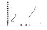
図9はこの電力変換装置による起動制御運転時における時間tと電力変換装置の出力周波数Fとの関係を示す線図である。周知の如く、空調負荷に応じて圧縮機を能力制御する電動機の回転速度範囲に対応して電力変換装置の出力周波数が決定される。そして、起動制御運転時には速度範囲の最低回転数に対応するA点の周波数、例えば、10〜20Hzから、室内ユニットに冷媒が急激に流入した場合に発生する冷媒音の発生を抑えるべく、所定の時間変化率にてC点、例えば、57Hzまで上昇させ、その周波数にて1〜2分程度保持して冷凍サイクルを安定させた後、再び所定の時間変化率にて段階的に周波数の上昇、保持(図示を省略)を繰り返して速度範囲の最高回転数に対応するD点の周波数、例えば、105Hzまで上昇させて起動制御運転を終了する。この起動制御運転の終了後、空調負荷に応じて電力変換装置の出力周波数Fの制御が行われ、圧縮機の能力制御に移行する。
【0004】
【発明が解決しようとする課題】
上述した従来の起動制御運転にあっては、起動時のA点から冷凍サイクルを安定させるために保持するC点まで、電力変換装置の出力周波数を上昇させる周波数の時間変化率として、空調負荷の変化に対応させて周波数を変える場合の変化率、例えば、1Hz/秒程度の比較的小さな時間変化率を採用していたので、圧縮機の振動が大きくなるという問題があった。
【0005】
また、起動時のA点を速度制御範囲の最低回転数に対応する周波数に設定していたので、最低周波数が高めに定められている場合には、GTR等のスイッチング素子に比較的大きな電流が流れて、稀にではあるがこのスイッチング素子を破壊させるという問題もあった。
【0006】
さらに、従来の起動制御では、A点の起動周波数を決定するに当たり、圧縮機における冷媒の寝込み量(残留量)や外気温等、負荷の増大要因を考慮しておらず、これらがスイッチング素子を破壊させる一因にもなっていた。
【0007】
一方、起動時のA点の周波数、すなわち、速度制御範囲の最低周波数を低めに定めた場合、3相電源の1相が断線した欠相状態で運転しても電流値が小さいために過電流保護回路が動作しないという問題もあった。
【0008】
本発明は上記の課題を解決するためになされたもので、第1の目的は起動時の電流値を低く抑えて電力変換装置を構成するスイッチング素子の破壊を未然に防止することのできる空気調和機を提供するにある。
【0009】
本発明の第2の目的は、起動時の振動を低く抑えることのできる空気調和機を提供するにある。
【0010】
本発明の第3の目的は欠相時の過電流保護を確実に実行することのできる空気調和機を提供するにある。
【0011】
【課題を解決するための手段】
請求項1に係る発明は、出力周波数が可変の電力変換装置を構成するスイッチング素子を介して圧縮機を駆動すると共に、前記電力変換装置の出力周波数を起動周波数から目標周波数に到達させて以降、予め定めた周波数制御範囲及び周波数の時間変化率で空調負荷に応じて変化させる空気調和機において、
起動時に、前記電力変換装置の出力周波数を、前記周波数範囲の最低値よりも所定値だけ低い起動周波数から、前記通常運転時における周波数の時間変化率よりも大きな変化率で、前記周波数制御範囲の最低値以下の周波数に向かうように上昇させ、その後通常運転時における周波数の時間変化率で周波数制御範囲の最高値まで上昇させたのち通常運転に移行させるように前記電力変換装置の出力周波数を制御する起動制御手段を備えたことを特徴とするものである。
【0012】
請求項2に係る発明は、請求項1に記載の空気調和機において、室外温度を検出する室外温度検出手段を備え、前記起動制御手段は検出された室外温度が高い場合ほど前記起動周波数を高い値に変更する ことを特徴とするものである。
【0013】
請求項3に係る発明は、請求項1に記載の空気調和機において、室外温度を検出する室外温度検出手段を備え、前記起動制御手段は検出された室外温度が高い場合ほど前記起動周波数を高い値に変更することを特徴とするものである。
【0014】
請求項4に係る発明は、請求項1に記載の空気調和機において、室外温度が予め定めた基準温度より低いとき前記圧縮機の巻線を加熱する巻線加熱手段を備え、前記起動制御手段は前記巻線加熱手段の動作時に、非動作時よりも前記起動周波数を低い値に変更することを特徴とするものである。
【0015】
請求項5に係る発明は、請求項1に記載の空気調和機において、室内温度を検出する室内温度検出手段と、室外温度を検出する室外温度検出手段とを備え、前記起動制御手段は検出された室内温度と室外温度との差が予め定めた基準値より大きい場合、前記起動周波数を低い値に変更することを特徴とするものである。
【0016】
請求項6に係る発明は、出力周波数が可変の電力変換装置を構成するスイッチング素子を介して圧縮機を駆動すると共に、前記電力変換装置の出力周波数を起動周波数から目標周波数に到達させて以降、予め定めた周波数制御範囲及び周波数の時間変化率で空調負荷に応じて変化させる空気調和機において、
起動時に、前記電力変換装置の出力周波数を、前記周波数範囲の最低値よりも所定値だけ低い起動周波数から、前記通常運転時における周波数の時間変化率よりも大きな変化率で、前記周波数制御範囲の最低値以下の周波数に向かうように上昇させ、その後通常運転時における周波数の時間変化率で前記目標周波数より低い第1の設定周波数まで上昇させ、前記第1の設定周波数に到達して以降、前記起動周波数より高く前記第1の設定周波数より低い第2の設定周波数まで下降させ、この第2の設定周波数に到達してから所定時間だけ前記第2の設定周波数に保持し、所定時間の経過後に前記目標周波数まで上昇させる起動制御手段を備えたことを特徴とするものである。
【0017】
請求項7に係る発明は、請求項6に記載の空気調和機において、前記第1の設定周波数は、前記目標周波数よりも低く、前記第2の設定周波数は空調負荷に応じて変化させる前記電力変換装置の出力周波数範囲の最低値である ことを特徴とする請求項6に記載の空気調和機。
【0018】
請求項8に係る発明は、請求項6に記載の空気調和機において、室外温度を検出する室外温度検出手段を備え、前記起動制御手段は検出された室外温度が予め定めた基準温度よりも低いとき前記第1及び第2の設定周波数を低い値に変更することを特徴とするものである。
【0019】
請求項9に係る発明は、請求項6に記載の空気調和機において、前記圧縮機の前回の運転停止時から今回の運転開始時までの運転停止時間を検出する停止時間検出手段を備え、前記起動制御手段は検出された運転停止時間が予め定めた基準値より長いとき前記第1及び第2の設定周波数を低い値に変更することを特徴とするものである。
【0020】
請求項10に係る発明は、請求項6に記載の空気調和機において、室外温度が予め定めた基準温度より低いとき前記圧縮機の巻線を加熱する巻線加熱手段を備え、前記起動制御手段は前記巻線加熱手段の動作時に、非動作時よりも前記第1及び第2の設定周波数を低い値に変更することを特徴とするものである。
【0021】
請求項11に係る発明は、請求項6に記載の空気調和機において、室内温度を検出する室内温度検出手段と、室外温度を検出する室外温度検出手段とを備え、前記起動制御手段は検出された室内温度と室外温度との差が予め定めた基準値より大きい場合、前記第1及び第2の設定周波数を低い値に変更することを特徴とするものである。
【0022】
請求項12に係る発明は、請求項6に記載の空気調和機において、前記電力変換装置に供給される電源電圧を検出する電圧検出手段を備え、前記起動制御手段は検出された電源電圧が定格電圧に対して予め定めた基準値より低い場合、前記第1及び第2の設定周波数を低い値に変更し、電源電圧が定格電圧に対して予め定めた基準値より高い場合、前記第1及び第2の設定周波数を高い値に変更することを特徴とするものである。
【0023】
【発明の実施の形態】
以下、本発明を図面に示す好適な実施形態に基づいて詳細に説明する。
【0024】
図1は本発明の第1の実施形態の制御系統の概略構成を示すブロック図である。同図において、1は単相交流電源であり、2はリモコン装置である。単相交流電源1に室内ユニット10が接続され、リモコン装置2から赤外線による制御信号が送信される。室内ユニット10は制御手段としてのマイクロコンピュータを含んでなる室内制御部11と、リモコン装置2の信号を受信して室内制御部11に加える受光部12と、室内制御部11によって回転数制御が行われる室内ファンモータ13と、室内温度を検出して室内制御部11に加える室内温度センサ14と、室内熱交換器温度を検出して室内制御部11に加える室内熱交換器温度センサ15とで構成されている。そして、この室内ユニット10に室外ユニット20が接続されている。
【0025】
室外ユニット20は制御手段としてのマイクロコンピュータを含んでなる室外制御部21と、交流を直流に変換した後、空調負荷に応じた周波数の交流を出力する電力変換装置としてのインバータ回路22と、その出力端に接続された圧縮機モータ23と、室外制御部21によって回転制御が行われる室外ファンモータ24と、インバータ回路22の入力電流を検出して室外制御部21に加える電流センサ25と、室外熱交換器の温度を検出して室外制御部21に加える室外熱交換器温度センサ26と、室外温度を検出して室外制御部21に加える室外温度センサ27とで構成されており、このうち、室外制御部21が前述の室内制御部11に対して2本の電源線ACLと1本の信号線SLとで接続され、室内制御部11から室外制御部21に動作電力を供給し、それぞれ内蔵するマイクロコンピュータどうしが制御情報を送受信するようになっている。
【0026】
上記のように構成された第1の実施形態の動作を、運転モードが暖房である場合について以下に説明する。
【0027】
単相交流電源1の電圧が室内制御部11に加えられると共に、電源線ACLを介して、室外制御部21に加えられる。室内制御部11は交流を整流、平滑してマイクロコンピュータ、受光部12及び室内ファンモータ13の動作に必要な直流に変換する。室外制御部21もまた交流を整流、平滑してマイクロコンピュータ、インバータ回路22、室外ファンモータ24等の動作に必要な直流に変換する。室内制御部11は室内ファンモータ13を速度制御するためのインバータを、室外制御部21は室外ファンモータ24を速度制御するするためのインバータをそれぞれ含むが、本発明に直接的に関係しないのでその説明を省略する。
【0028】
ここで、リモコン装置2から運転指令と、運転モード、室内温度、風量等の設定信号とが赤外線の直列信号として放射されると、受光部12がそれらの信号を受信し、並列信号に変換して室内制御部11を構成する図示省略のマイクロコンピュータに加える。このマイクロコンピュータは室内熱交換器温度センサ15の温度検出値に応じて室内ファンモータ13を起動制御すると共に、リモコン装置2の設定風量に追随するように制御する。また、室内制御部11を構成するマイクロコンピュータはリモコン装置2による設定室温と、室内温度センサ14による検出温度とを比較し、そのときの空調負荷に応じた空調能力を発揮するようなインバータ回路22の出力周波数を演算し、運転モード信号と併せて室外制御部21に送信する。
【0029】
次に、室外制御部21を構成するマイクロコンピュータは運転モードに応じて図示を省略した四方弁を制御すると共に、室内制御部から送信された周波数の交流が出力されるようにインバータ回路22を制御して、圧縮機モータ23を速度制御すると共に、室外ファンモータ24の速度をも制御する。また、室外制御部21を構成するマイクロコンピュータは室外熱交換器温度センサ26の温度検出値に基づいて、暖房運転時における室外熱交換器の着霜の有無を判定し、着霜時には短時間だけ四方弁を切換える等の操作を実行して除霜する。また、室外制御部21を構成するマイクロコンピュータは電流センサ25の検出信号に基づいてインバータ回路22の入力電流が予め定めた閾値を超えるとき、インバータ回路22の動作を停止してスイッチング素子の破壊を未然に防止する機能をも備えている。
【0030】
なお、上述した空調負荷に対応する通常運転時におけるインバータ回路22の制御、起動時における室内ファンモータ13の制御、除霜制御等については種々に提案され、かつ、公知でもあるのでこれ以上の説明を省略し、起動制御について図2乃至図5及び図9をも参照して以下に説明する。
【0031】
図9に示した従来の起動制御におけるA点の起動周波数は、空調負荷に対応した制御範囲の最低値Fmin に設定したのに対して、本実施形態では起動周波数Fst0 として制御範囲の最低値Fmin よりも低い値に設定する。そして、起動周波数Fst0 から時間変化率dF/dt=βにて上昇せしめ、制御範囲の最低値Fmin よりも低い周波数Fa に到達した時点にて通常運転時の時間変化率dF/dt=αにて、制御範囲の最高値Fmax まで、段階的に上昇(図面では簡単化のために直線で示した)させ、これ以降、通常運転に移行すると共に、周波数を下降させる場合には上昇時と同一の時間変化率dF/dt=αにて変化させる。
【0032】
因みに、空調負荷に応じた周波数制御範囲の最低値が30Hz、最高値が105Hzであったとすると、起動周波数Fst0 を10Hzに、時間変化率変更周波数Fa を20Hzに設定し、通常運転時の時間変化率αが1Hz/秒であれば、起動時の時間変化率βを3Hz/秒程度に設定すると好結果が得られる。
【0033】
一般に、圧縮機モータ23の回転数に対応する電力変換装置の出力周波数と入力電流との間には、図3(a)の曲線Pに示すように回転数の増大に応じて指数関数的に単調に増大する。従って、図2に示したように、起動周波数Fst0 を周波数制御範囲の最低値Fmin よりも低く設定することによって、起動電流を低く抑えることができる。また、起動周波数Fst0 から周波数を上昇させる際に、通常運転時の時間変化率よりも大きい時間変化率を採用することによって、時間変化率を低くしたことに起因する振動の発生を防止することができる。
【0034】
ところで、起動周波数Fst0 を決定する場合、暖房運転時の外気温度が低いときの負荷は必然的に大きくなり、また、圧縮機に残留する冷媒量、すなわち、冷媒寝込み量が多くなると、これを駆動する入力電流も図3(b)の曲線Qに示すように指数関数的に増大する。このような場合、起動周波数Fst0 をより低く設定することによって、起動電流を低く抑えることができる。反対に、室温と外気温との温度差が大きい場合には負荷が大きく、その温度差が少ないときには負荷も小さい。従って、温度差が大きいとき起動周波数Fst0 を下げ、温度差が小さいとき起動周波数を上げることによって起動電流の抑制のみならず、起動特性を向上させることができる。
【0035】
以下、起動周波数Fst0 の決定を含めた制御について、例えば、室内制御部11を構成するマイクロコンピュータの処理手順を図4及び図5を参照して説明する。
先ず、ステップ101 で起動指令が与えられたとすると、ステップ102 で設定された電力変換装置の周波数制御範囲の最高値Fmax 、最低値Fmin 、リモコン装置2による設定室温Ts 、室内温度センサ14による検出室温Ta 、設定された時間変化率変更周波数Fa 、時間変化率α,βを読込む。続いて、ステップ103 にて、図5(a)〜(e)に示すいずれかの方法で起動周波数Fst0 を決定する。続いて、ステップ104 で時間tを計測すると共に、起動周波数Fst0 から時間変化率βに従って運転周波数Fを増大させる。次のステップ105 では運転周波数Fが時間変化率変更周波数Fa に到達したか否かを判定し、到達するまでステップ104 の処理を繰返す。
【0036】
次に、運転周波数Fが時間変化率変更周波数Fa に到達したと判定すると、ステップ106 にて、時間変化率変更周波数Fa から時間変化率αに従って運転周波数Fを増大させる。次のステップ107 では運転周波数Fが最高値Fmax に到達したか否かを判定し、到達するまでステップ106 の処理を繰返す。なお、ここでは、図面の簡単化のために、周波数を所定時間だけ保持しつつ順次増大する処理を省略して示してある。
【0037】
次に、運転周波数Fが最高値Fmax に到達したと判定すると、空調負荷に対応した通常の空調制御に移行する。そこで、ステップ108 にて設定室温Ts が検出室温Ta より大きいか否かを判定する。このとき、設定室温Ts が検出室温Ta より小さい場合にはステップ110 にて時間変化率αにて運転周波数Fを減少させ、その後、ステップ111 で停止指令の有無を判定して、停止指令が無い場合には再びステップ108 の処理に戻り、このステップ108 にて設定室温Ts が検出室温Ta より大きいと判定した場合には、ステップ109 にて時間変化率αにて運転周波数Fを増大させる処理を実行してステップ111 の処理に進む。そして、停止指令が有れば、そこで処理を終了する。
【0038】
図5は起動周波数Fst0 を決定する種々の方法を示したもので、(a)のステップ103Aに示したように一定値aHzに決定したり、(b)のステップ103Bに示したようにそのときの外気温をTo (℃)として、To +15Hzに決定したりする。あるいは、(c)のステップ103Cに示したように前回の停止時刻から今回起動するまでの停止時間をh(時間)として、2・h+10Hzに設定することにより、圧縮機における冷媒寝込み量に応じて起動周波数Fst0 を適切に定める。(d)は圧縮機モータ23が巻線加熱器を備え、気温の低いときにのみ巻線加熱器に通電する加熱手段を動作させるものを対象として、ステップ103Dにて加熱手段が動作中か否かを判定し、動作中であればステップ103Eにて起動周波数Fst0 を10Hzに設定し、動作中でなれければステップ103Fにて15Hzに設定する。この結果、圧縮機の負荷に応じて起動周波数Fst0 を適切に変更することができる。(e)は設定室温Ts と検出室温Ta との差、すなわち、空調負荷に応じて起動周波数Fst0 を変更しようとするもので、ステップ103GにてTs とTa との差が基準偏差ΔTref より小さいか否かを判定し、小さい場合にはステップ103Hにて一定値aHzに決定し、小さくない場合にはステップ103Iにてa−ρHzに決定する。
【0039】
かくして、第1の実施形態によれば、起動周波数を負荷に応じて適当に設定することにより起動時の電流値を低く抑えることができる。また、起動周波数の時間変化率を大きくすることにより起動時の振動を低く抑えることができる。
【0040】
なお、上記実施形態では、室内制御部11を構成するマイクロコンピュータに図4及び図5に示す処理機能を持たせたが、これらの処理機能を室外制御部21を構成するマイクロコンピュータに持たせたり、あるいは、室内制御部11を構成するマイクロコンピュータと室外制御部21を構成するマイクロコンピュータにこれらの処理機能を分散させるようにしても良い。
【0041】
また、上記第1の実施形態では、外気温、運転停止時間、巻線加熱手段の動作状態、空調負荷等、電流値の増大や冷媒流通音の発生に影響する要因毎に起動周波数Fst0 を変更したが、これら電流値の増大や冷媒流通音の発生に影響する複数の要因を加味して起動周波数Fst0 を設定変更することにより、起動特性をさらに改善することができる。
【0042】
図6は本発明の第2の実施形態に対応する暖房モードにおける起動制御運転時の電力変換装置の出力周波数Fと時間との関係を示す線図である。この場合、ハードウェアの構成は図1に示した第1の実施形態と同一であるのでその説明を省略し、起動周波数Fst0 の決定及び起動時の時間変化率もまた第1の実施形態と同様である。しかるに、本実施形態では時間変化率変更周波数Fa に到達した以降、通常の時間変化率αで増大させるが、周波数変更範囲の最低値Fmin よりも大きい第1の設定周波数Fs1としてのB点、例えば45Hzまで上昇させる。続いて、周波数変更範囲の最低値Fmin 又はこれに近い第2の設定周波数Fs2としてのC点、例えば、28Hzまで下降させ、この周波数にて180秒間保持し、続いて、通常の時間変化率αにてD点、例えば、57Hzまで上昇させ、この周波数にて60秒間保持した後、さらに、通常の時間変化率αにて90Hzまで上昇させ、この周波数にて180秒間保持した後、起動制御運転の最終的な目標周波数としての周波数変更範囲の最高値Fmax 、例えば、105Hzまで上昇させ、180秒間保持して起動制御運転を終了する。その後、通常運転に移行すると共に、周波数を下降させる場合には上昇時と同一の時間変化率dF/dt=αにて変化させる。
【0043】
上述したように、時間変化率変更周波数Fa に到達した以降、通常の時間変化率αで周波数変更範囲の最低値Fmin よりも大きい第1の設定周波数Fs1まで上昇させた後、第2の設定周波数Fs2に下降させる操作を加えることにより、インバータ回路22と圧縮機モータ23との3相結線のうちの1本が断線する、いわゆる、欠相を早期に検出することができる。すなわち、時間変化率変更周波数Fa から順次階段状に周波数を上昇させる場合、初期段階では周波数が低いために電流センサ25の検出値も小さく、欠相を判断できる電流を生じない。そのため、周波数をD点まで増大させる段階で漸く欠相と判定し得る電流値に至る。本実施形態では起動制御運転期間の初期の段階にて時間変化率変更周波数Fa から第1の設定周波数Fs1に上昇させてから第2の設定周波数Fs2に下降させることにより、欠相を判断できる電流を生じさせる。この結果、インバータ回路22を構成するスイッチング素子としてのGTRを破損させる原因を早期に検出し、必要な措置を講じることができる。
【0044】
以下、第1及び第2の設定周波数Fs1,Fs2を含めた制御について、例えば、室内制御部11を構成するマイクロコンピュータの処理手順を示す図7及び図8を参照して説明する。
先ず、図7に示したように、ステップ201 で起動指令が与えられたとすると、ステップ202 で設定された電力変換装置の周波数制御範囲の最高値Fmax 、最低値Fmin 、リモコン装置2による設定室温Ts 、室内温度センサ14による検出室温Ta 、設定された起動周波数Fst0 ,時間変化率変更周波数Fa 、時間変化率α,β、階段状に上昇させる途中の周波数F1 ,F2 及び周波数保持時間ts1〜ts4を読込む。続いて、ステップ203 にて、図8(a)〜(f)に示すいずれかの方法で第1及び第2の設定周波数Fs1,Fs2を決定する。続いて、ステップ204 で時間tを計測すると共に、起動周波数Fst0 から時間変化率βに従って運転周波数Fを増大させる。次のステップ205 では運転周波数Fが時間変化率変更周波数Fa に到達したか否かを判定し、到達するまでステップ204 の処理を繰返す。
【0045】
次に、運転周波数Fが時間変化率変更周波数Fa に到達したと判定すると、ステップ206 にて、時間変化率変更周波数Fa から時間変化率αに従って運転周波数Fを増大させる。次のステップ207 では運転周波数Fが第1の設定周波数Fs1、例えば、45Hzに到達したか否かを判定し、到達するまでステップ206 の処理を繰返す。そして、運転周波数Fが第1の設定周波数Fs1に到達したと判定すると、ステップ208 にて、第1の設定周波数Fs1から時間変化率αに従って運転周波数Fを減少させる。次のステップ209 では運転周波数Fが第2の設定周波数Fs2、例えば、28Hzに到達したか否かを判定し、到達するまでステップ208 の処理を繰返す。運転周波数Fが第2の設定周波数Fs2に到達すると、ステップ210 で時間計測を開始すると共に、計測時間が設定値ts1、例えば、180秒を経過したか否かを判定し、設定値ts1を経過した時点にてステップ211 以下の処理を実行する。
【0046】
ステップ211 では第2の設定周波数Fs2から時間変化率αに従って運転周波数Fを増大させる。次のステップ212 では運転周波数Fが階段状に上昇させる最初の周波数F1 、例えば、57Hzに到達したか否かを判定し、到達するまでステップ211 の処理を繰返す。そして、運転周波数Fが周波数F1 に到達したと判定すると、ステップ213 にて、時間設定値ts2、例えば、60秒を経過したか否かを判定し、設定値ts2を経過した以降、同様な周波数増大操作を繰返す。
【0047】
次に、ステップ214 にて周波数制御範囲の最高値に到達したか否かを判定し、到達すればステップ215 にて時間計測を開始すると共に、計測時間が設定値ts4、例えば、180秒を経過したか否かを判定し、設定値ts4を経過した時点から空調負荷に応じた能力制御に移行する。そこで、ステップ216 にて設定室温Ts が検出室温Ta より高いか否かを判定する。このとき、設定室温Ts が検出室温Ta より低い場合にはステップ218 にて時間変化率αにて運転周波数Fを減少させ、その後、ステップ219 で停止指令の有無を判定して、停止指令が無い場合には再びステップ216 以下の処理に戻り、このステップ216 にて設定室温Ts が検出室温Ta より高いと判定した場合には、ステップ217 にて時間変化率αにて運転周波数Fを増大させる処理を実行してステップ219 の処理に進む。そして、停止指令が有れば、そこで処理を終了する。
【0048】
図8は第1及び第2の設定周波数Fs1,Fs2を決定する種々の方法を示したもので、(a)のステップ203Aに示したようにFs1をbHzに、Fs2をcHzに決定したり、(b)に示したようにステップ203Bにて外気温をTo が予め定めた閾値Tref より低いか否かを判定し、Tref より低い場合にははステップ203CにてFs1,Fs2としてb−γHz,c−γHzに決定し、Tref 以上であればステップ203DにてFs1,Fs2としてbHz,cHzに決定する。
【0049】
あるいは、(c)のステップ203Eに示したように前回の停止時刻から今回起動するまでの停止時間をh(時間)を計測し、ステップ203Fにて停止時間hが基準値href より長いか否かを判定し、長いと判定したとき、ステップ203GにてFs1=b−δHzに、Fs2=c−δHzにそれぞれ設定し、停止時間hが基準値href より長くない場合にはステップ203HでFs1,Fs2としてb,cに決定することにより、圧縮機における冷媒寝込み量に応じて第1及び第2の設定周波数を適切に定める。
【0050】
(d)は圧縮機モータ23が巻線加熱器を備え、気温の低いときにのみ巻線加熱器に通電する加熱手段を動作させるものを対象として、ステップ203Iにて加熱手段が動作中か否かを判定し、動作中であればステップ203JにてFs1=b−εHzに、Fs2=c−εHzにそれぞれ設定し、動作中でなれければステップ203KでFs1=bHz、Fs2=cHzに決定する。この結果、圧縮機の負荷に応じて第1及び第2の設定周波数を適切に変更することができる。
【0051】
(e)は室内温度Ta と室外温度To との差、すなわち、空調負荷に応じて設定周波数Fs1,Fs2を変更しようとするもので、ステップ203LにてTa とTo との差が基準偏差ΔTref より大きいか否かを判定し、大きい場合にはステップ203Mにて、Fs1=b−ηHz、Fs2=c−ηHzにそれぞれ設定し、大きくない場合にはステップ203NにてFs1=bHz、Fs2=cHzに設定する。
【0052】
(f)は電源電圧の許容範囲が±15%に制限されている場合に、この許容範囲にあってもその定格電圧Vs に対して一定値以上の差がある場合に第1及び第2の周波数設定値Fs1,Fs2を変更するもので、ステップ203Oにて第1及び第2の周波数設定値としてFs1=bHz、Fs2=cHzに設定した後、ステップ203Pにて定格電圧Vs と測定電圧Va との偏差分が基準値ΔVref 以上か否かを検出し、基準値以上であればステップ203Qにて定格電圧Vs に対して測定電圧Va が低いか否かを判定し、低い場合にはステップ203Rにて、Fs1=b−θHz、Fs2=c−θHzにそれぞれ設定し、低くない場合にはステップ203SにてFs1=b+θHz、Fs2=c+θHzにそれぞれ設定する。一方、ステップ203Pにて定格電圧Vs と測定電圧Va との偏差分が基準値ΔVref より小さいと判定した場合には第1及び第2の周波数設定値Fs1=b、Fs2=cをそのまま採用する。
【0053】
ところで、図6に示した第2の実施形態では、起動制御運転の最終の目標周波数を圧縮機の能力制御範囲の最高値Fmax としたが、この目標周波数は最高値Fmax に近似した値であれば上述したと同様な動作をさせることができる。なお、上述した、定数b,c,γ,δ,ε,η,θ,ρは予め定めておくものとする。
【0054】
かくして、第2の実施形態によれば、負荷の大小、電源電圧の高低等、インバータ回路22を構成するスイッチング素子に大きな電流が流れやすいとき第1及び第2の設定周波数を高く設定し、反対に、電流が少ないと予測されるとき第1及び第2の設定周波数を低く設定することにより、インバータ回路22を構成するスイッチング素子としてのGTRを破損させる欠相を早期に検出し、必要な措置を講じることができる。
【0055】
なお、上記実施形態では、室内制御部11を構成するマイクロコンピュータに図7及び図8に示す処理機能を持たせたが、これらの処理機能を室外制御部21を構成するマイクロコンピュータに持たせたり、あるいは、室内制御部11を構成するマイクロコンピュータと室外制御部21を構成するマイクロコンピュータにこれらの処理機能を分散させるようにしても良い。
【0056】
また、上記第2の実施形態では外気温、運転停止時間、巻線加熱手段の動作状態、空調負荷、電源電圧等、電流値に影響する要因毎に第1及び第2の設定周波数Fs1,Fs2を変更したが、これら電流値に影響する複数の要因を加味して第1及び第2の設定周波数Fs1,Fs2を設定変更することにより、欠相時の過電流保護をより一層確実にすることができる。
【0057】
【発明の効果】
以上の説明によって明らかなように、請求項1に係る発明によれば、暖房運転モードでの起動時に空調負荷に応じて変化させる周波数範囲の最低値よりも所定値だけ低い起動周波数から、通常時よりも大きな時間変化率で、周波数範囲の最低値に向かうように電力変化装置の出力周波数を制御するので、起動時の電流値を低く抑えて電力変換装置を構成するスイッチング素子の破壊を未然に防止すると共に、起動時の振動を低く抑えることができる。
【0058】
請求項2に係る発明によれば、室外温度が高い場合ほど起動周波数を高い値に変更し、請求項3に係る発明によれば、圧縮機の運転停止時間が長くなるほど起動周波数を高い値に変更し、請求項4に係る発明によれば、巻線加熱手段の動作時に、非動作時よりも起動周波数を低い値に変更し、請求項5に係る発明によれば、室内温度と室外温度との差が大きい場合に、起動周波数を低い値に変更するので、それぞれスイッチング素子の破壊防止及び起動時の振動低減の効果が高められる。
【0059】
請求項6に係る発明によれば、暖房運転モードでの起動時に、電力変換装置の出力周波数を、起動周波数から目標周波数より低い第1の設定周波数まで上昇させ、第1の設定周波数に到達して以降、起動周波数より高く第1の設定周波数より低い第2の設定周波数まで下降させ、この第2の設定周波数に到達してから所定時間だけ第2の設定周波数に保持し、所定時間の経過後に目標周波数まで上昇させるので、欠相時の過電流保護を確実に実行することのできる。
【0060】
請求項7に係る発明によれば、第1の設定周波数は、目標周波数よりも低く、第2の設定周波数は空調負荷に応じて変化させる電力変換装置の出力周波数範囲の最低値に設定し、請求項8に係る発明によれば、室外温度が予め定めた基準温度よりも低いとき第1及び第2の設定周波数を低い値に変更し、請求項9に係る発明によれば、運転停止時間が予め定めた基準値より長いとき、第1及び第2の設定周波数を低い値に変更し、請求項10に係る発明によれば、巻線加熱手段の動作時に、第1及び第2の設定周波数を非動作時よりも低い値に変更し、請求項11に係る発明によれば、室内温度と室外温度との差が予め定めた基準値より大きい場合、第1及び第2の設定周波数を低い値に変更し、請求項12に係る発明によれば、電源電圧が定格電圧比較して基準値よりも低い場合に第1及び第2の設定周波数を低い値に変更し、基準値よりも高い場合に第1及び第2の設定周波数を高い値に変更するので、それぞれ過電流保護の効果が高められる。
【図面の簡単な説明】
【図1】本発明に係る空気調和機の第1の実施形態の制御部の構成を示すブロック図。
【図2】図1に示した第1の実施形態の概略動作を説明するために、電力変換装置の出力周波数と時間との関係を示した線図。
【図3】図1に示した第1の実施形態の概略動作を説明するために、電力変換装置の入力電流と出力周波数との関係、及び、入力電流と冷媒寝込み量との関係をそれぞれ示した線図。
【図4】図1に示した第1の実施形態の動作を説明するために、室内制御部を構成するマイクロコンピュータの処理手順を示すフローチャート。
【図5】図4に示したフローチャートの主要な処理手順の一つの具体例を示した図。
【図6】本発明に係る空気調和機の第2の実施形態の室内制御部を構成するマイクロコンピュータの処理手順を示すフローチャート。
【図7】図6に示した第2の実施形態の概略動作を説明するために、電力変換装置の出力周波数と時間との関係を示した線図。
【図8】図7に示したフローチャートの主要な処理手順の一つの具体例を示した図。
【図9】従来の空気調和機の動作を説明するために、電力変換装置の出力周波数と時間との関係を示した線図。
【符号の説明】
1 単相交流電源
2 リモコン装置
10 室内ユニット
11 室内制御部
12 受光部
13 室内ファンモータ
14 室内温度センサ
15 室内熱交換器温度センサ
20 室外ユニット
21 室外制御部
22 インバータ回路
23 圧縮機モータ
24 室外ファンモータ
25 電流センサ
26 室外熱交換器温度センサ
27 室外温度センサ[0001]
BACKGROUND OF THE INVENTION
The present invention relates to an air conditioner that drives a compressor via a power converter having a variable output frequency and changes the output frequency according to an air conditioning load.
[0002]
[Prior art]
In general, this type of power conversion device, which is generally called an inverter, converts a primary side alternating current into a direct current, and then converts it to a required frequency by turning on and off, for example, a high power transistor (hereinafter referred to as GTR) as a switching element. Thus, it is a device that outputs to the secondary side, and is becoming a general means of a capacity control method by rotational speed control.
[0003]
FIG. 9 is a diagram showing the relationship between the time t and the output frequency F of the power converter during the start-up control operation by the power converter. As is well known, the output frequency of the power converter is determined in accordance with the rotational speed range of the electric motor whose capacity is controlled according to the air conditioning load. In order to suppress the generation of refrigerant noise that occurs when the refrigerant suddenly flows into the indoor unit from the frequency at point A corresponding to the minimum number of revolutions in the speed range, for example, 10 to 20 Hz, during start-up control operation, Increase to point C at the time change rate, for example, 57 Hz, hold at that frequency for about 1 to 2 minutes to stabilize the refrigeration cycle, then increase the frequency step by step again at a predetermined time change rate, Holding (not shown) is repeated to increase the frequency at point D corresponding to the maximum rotational speed in the speed range, for example, 105 Hz, and the start control operation is terminated. After the start control operation is completed, the output frequency F of the power converter is controlled in accordance with the air conditioning load, and the process proceeds to compressor capacity control.
[0004]
[Problems to be solved by the invention]
In the conventional start-up control operation described above, the time change rate of the frequency for increasing the output frequency of the power converter from the point A at start-up to the point C that is held to stabilize the refrigeration cycle, Since a change rate when changing the frequency in response to the change, for example, a relatively small time change rate of about 1 Hz / second, was adopted, there was a problem that the vibration of the compressor increased.
[0005]
In addition, since the point A at the time of start-up is set to a frequency corresponding to the minimum rotational speed of the speed control range, when the minimum frequency is set higher, a relatively large current is applied to a switching element such as a GTR. There was also a problem that this switching element was destroyed, although rarely.
[0006]
Further, in the conventional start-up control, when determining the start-up frequency at the point A, the increase factor of the load such as the refrigerant stagnation amount (residual amount) and the outside air temperature in the compressor is not taken into consideration. It also contributed to the destruction.
[0007]
On the other hand, when the frequency at the point A at the time of start-up, that is, the lowest frequency of the speed control range is set low, the current value is small even if the three-phase power supply is operated in an open-phase state in which one phase is disconnected. There was also a problem that the protection circuit did not operate.
[0008]
The present invention has been made in order to solve the above-described problems, and a first object of the present invention is to provide an air conditioner capable of preventing destruction of switching elements constituting a power conversion device by suppressing a current value at startup to a low level. In providing a machine.
[0009]
A second object of the present invention is to provide an air conditioner that can suppress vibration at the time of startup to a low level.
[0010]
A third object of the present invention is to provide an air conditioner that can reliably carry out overcurrent protection during phase loss.
[0011]
[Means for Solving the Problems]
The invention according to
At the time of start-up, the output frequency of the power conversion device is changed from a start-up frequency that is lower than a minimum value of the frequency range by a predetermined value, at a change rate greater than the time change rate of the frequency during the normal operation, Control the output frequency of the power converter so that the frequency is increased to the frequency below the minimum value, then increased to the maximum value in the frequency control range at the rate of time change in frequency during normal operation, and then shifted to normal operation. It is characterized by comprising a starting control means.
[0012]
The invention according to
[0013]
The invention according to claim 3 is the air conditioner according to
[0014]
According to a fourth aspect of the present invention, in the air conditioner according to the first aspect of the present invention, the air conditioner includes a winding heating means for heating the winding of the compressor when an outdoor temperature is lower than a predetermined reference temperature, and the start control means Is characterized in that the start-up frequency is changed to a lower value when the winding heating means is operating than when it is not operating.
[0015]
According to a fifth aspect of the present invention, in the air conditioner according to the first aspect of the present invention, the air conditioner includes an indoor temperature detecting means for detecting an indoor temperature and an outdoor temperature detecting means for detecting an outdoor temperature, wherein the activation control means is detected. When the difference between the indoor temperature and the outdoor temperature is larger than a predetermined reference value, the activation frequency is changed to a low value.
[0016]
The invention according to claim 6 drives the compressor via a switching element that constitutes a power converter having a variable output frequency, and after the output frequency of the power converter reaches the target frequency from the startup frequency, In an air conditioner that changes according to the air conditioning load at a predetermined frequency control range and frequency change rate over time,
At the time of start-up, the output frequency of the power conversion device is changed from a start-up frequency that is lower than a minimum value of the frequency range by a predetermined value, at a change rate greater than the time change rate of the frequency during the normal operation, The frequency is increased so as to go to a frequency below the minimum value, and then increased to a first set frequency lower than the target frequency at a time change rate of the frequency during normal operation, and after reaching the first set frequency, The frequency is lowered to a second set frequency that is higher than the start frequency and lower than the first set frequency, and is held at the second set frequency for a predetermined time after reaching the second set frequency. A starting control means for increasing to the target frequency is provided.
[0017]
The invention according to
[0018]
The invention according to
[0019]
The invention according to claim 9 is the air conditioner according to claim 6, further comprising stop time detection means for detecting an operation stop time from the previous operation stop of the compressor to the current operation start, The start control means is characterized in that the first and second set frequencies are changed to low values when the detected operation stop time is longer than a predetermined reference value.
[0020]
A tenth aspect of the present invention is the air conditioner according to the sixth aspect, further comprising: a winding heating means for heating the winding of the compressor when the outdoor temperature is lower than a predetermined reference temperature, and the start control means. Is characterized in that the first and second set frequencies are changed to lower values when the winding heating means is operating than when the winding heating means is not operating.
[0021]
According to an eleventh aspect of the present invention, in the air conditioner according to the sixth aspect of the present invention, the air conditioner includes an indoor temperature detecting means for detecting an indoor temperature and an outdoor temperature detecting means for detecting an outdoor temperature, wherein the activation control means is detected. When the difference between the indoor temperature and the outdoor temperature is larger than a predetermined reference value, the first and second set frequencies are changed to low values.
[0022]
The invention according to claim 12 is the air conditioner according to claim 6, further comprising voltage detection means for detecting a power supply voltage supplied to the power converter, wherein the activation control means has a rated power supply voltage rated. When the voltage is lower than a predetermined reference value, the first and second set frequencies are changed to low values, and when the power supply voltage is higher than a predetermined reference value with respect to the rated voltage, the first and second The second set frequency is changed to a high value.
[0023]
DETAILED DESCRIPTION OF THE INVENTION
Hereinafter, the present invention will be described in detail based on preferred embodiments shown in the drawings.
[0024]
FIG. 1 is a block diagram showing a schematic configuration of a control system according to the first embodiment of the present invention. In the figure, 1 is a single-phase AC power source and 2 is a remote control device. The
[0025]
The
[0026]
The operation of the first embodiment configured as described above will be described below in the case where the operation mode is heating.
[0027]
The voltage of the single-phase
[0028]
Here, when the operation command and the setting signal such as the operation mode, the room temperature, and the air volume are radiated from the
[0029]
Next, the microcomputer constituting the
[0030]
Note that the control of the
[0031]
The starting frequency at point A in the conventional starting control shown in FIG. 9 is set to the minimum value Fmin of the control range corresponding to the air conditioning load, whereas in this embodiment, the minimum value Fmin of the control range is set as the starting frequency Fst0. Set to a lower value. Then, it is increased from the starting frequency Fst0 at the time change rate dF / dt = β, and at the time when the frequency Fa is lower than the minimum value Fmin of the control range, at the time change rate dF / dt = α during normal operation. When the frequency is increased to the maximum value Fmax of the control range in a stepwise manner (shown as a straight line in the drawing for simplification), the operation is shifted to normal operation and the frequency is decreased. The time change rate is changed at dF / dt = α.
[0032]
Incidentally, if the minimum value of the frequency control range according to the air conditioning load is 30 Hz and the maximum value is 105 Hz, the start frequency Fst0 is set to 10 Hz, the time change rate changing frequency Fa is set to 20 Hz, and the time change during normal operation is set. If the rate α is 1 Hz / second, good results can be obtained by setting the time change rate β at startup to about 3 Hz / second.
[0033]
Generally, between the output frequency of the power converter corresponding to the rotation speed of the
[0034]
By the way, when the starting frequency Fst0 is determined, the load when the outside air temperature during the heating operation is low inevitably increases, and when the amount of refrigerant remaining in the compressor, that is, the amount of refrigerant stagnation increases, the load is driven. The input current to be increased also exponentially as shown by a curve Q in FIG. In such a case, the starting current can be kept low by setting the starting frequency Fst0 lower. Conversely, when the temperature difference between the room temperature and the outside air temperature is large, the load is large, and when the temperature difference is small, the load is small. Therefore, by reducing the start-up frequency Fst0 when the temperature difference is large and increasing the start-up frequency when the temperature difference is small, not only the start-up current can be suppressed but also the start-up characteristics can be improved.
[0035]
Hereinafter, the control procedure including the determination of the activation frequency Fst0 will be described with reference to FIGS. 4 and 5, for example, with reference to FIGS. 4 and 5.
First, if an activation command is given in
[0036]
Next, when it is determined that the operation frequency F has reached the time change rate change frequency Fa, the operation frequency F is increased from the time change rate change frequency Fa according to the time change rate α in
[0037]
Next, when it is determined that the operating frequency F has reached the maximum value Fmax, the routine proceeds to normal air conditioning control corresponding to the air conditioning load. Therefore, in
[0038]
FIG. 5 shows various methods for determining the starting frequency Fst0. As shown in
[0039]
Thus, according to the first embodiment, the current value at the time of start-up can be kept low by appropriately setting the start-up frequency according to the load. Moreover, the vibration at the time of starting can be suppressed low by increasing the time change rate of the starting frequency.
[0040]
In the above embodiment, the microcomputer constituting the
[0041]
Further, in the first embodiment, the start-up frequency Fst0 is changed for each factor that affects the increase in the current value and the generation of refrigerant circulation sound, such as the outside air temperature, the operation stop time, the operating state of the winding heating means, and the air conditioning load. However, the start-up characteristics can be further improved by changing the setting of the start-up frequency Fst0 in consideration of a plurality of factors that affect the increase in the current value and the generation of the refrigerant circulation sound.
[0042]
FIG. 6 is a diagram showing the relationship between the output frequency F and the time of the power conversion device during start-up control operation in the heating mode corresponding to the second embodiment of the present invention. In this case, since the hardware configuration is the same as that of the first embodiment shown in FIG. 1, the description thereof is omitted, and the determination of the activation frequency Fst0 and the time change rate at the time of activation are also the same as in the first embodiment. It is. However, in the present embodiment, after reaching the time change rate change frequency Fa, the normal time change rate α is increased, but the B point as the first set frequency Fs1, which is larger than the minimum value Fmin of the frequency change range, for example, Increase to 45 Hz. Subsequently, the frequency change range is lowered to the minimum value Fmin of the frequency change range or the second set frequency Fs2 close to this, for example, to 28 Hz, held at this frequency for 180 seconds, and then the normal time change rate α Increase to point D, for example, 57 Hz, hold at this frequency for 60 seconds, further increase to 90 Hz at normal time change rate α, hold at this frequency for 180 seconds, then start control operation The maximum value Fmax of the frequency change range as the final target frequency is raised to, for example, 105 Hz, held for 180 seconds, and the start control operation is terminated. Thereafter, the operation shifts to normal operation, and when the frequency is lowered, it is changed at the same time change rate dF / dt = α as that at the time of increase.
[0043]
As described above, after reaching the time change rate change frequency Fa, the first set frequency Fs1 higher than the minimum value Fmin of the frequency change range is increased at the normal time change rate α, and then the second set frequency is set. By adding the operation of lowering to Fs2, it is possible to detect so-called phase loss, in which one of the three-phase connections between the
[0044]
Hereinafter, the control including the first and second set frequencies Fs1 and Fs2 will be described with reference to FIGS. 7 and 8 showing the processing procedure of the microcomputer constituting the
First, as shown in FIG. 7, if a start command is given in step 201, the maximum value Fmax, the minimum value Fmin of the frequency control range of the power converter set in
[0045]
Next, when it is determined that the operation frequency F has reached the time change rate change frequency Fa, the operation frequency F is increased from the time change rate change frequency Fa according to the time change rate α in
[0046]
In
[0047]
Next, in
[0048]
FIG. 8 shows various methods for determining the first and second set frequencies Fs1 and Fs2. As shown in
[0049]
Alternatively, as shown in
[0050]
(D) shows whether the
[0051]
(E) is to change the set frequencies Fs1 and Fs2 depending on the difference between the indoor temperature Ta and the outdoor temperature To, that is, the air conditioning load. In
[0052]
(F) shows that when the allowable range of the power supply voltage is limited to ± 15% and there is a difference of a certain value or more with respect to the rated voltage Vs even within this allowable range, The frequency setting values Fs1 and Fs2 are changed. In step 203O, the first and second frequency setting values are set to Fs1 = bHz and Fs2 = cHz. Then, in
[0053]
By the way, in the second embodiment shown in FIG. 6, the final target frequency of the start control operation is set to the maximum value Fmax of the compressor capacity control range, but this target frequency may be a value approximate to the maximum value Fmax. For example, the same operation as described above can be performed. The constants b, c, γ, δ, ε, η, θ, and ρ described above are determined in advance.
[0054]
Thus, according to the second embodiment, when a large current tends to flow through the switching elements constituting the
[0055]
In the above embodiment, the microcomputer constituting the
[0056]
In the second embodiment, the first and second set frequencies Fs1, Fs2 are determined for each factor affecting the current value, such as the outside air temperature, the operation stop time, the operating state of the winding heating means, the air conditioning load, and the power supply voltage. However, by changing the settings of the first and second set frequencies Fs1 and Fs2 in consideration of multiple factors that affect these current values, it is possible to further ensure overcurrent protection during phase loss. Can do.
[0057]
【The invention's effect】
As is apparent from the above description, according to the invention according to
[0058]
According to the invention of
[0059]
According to the invention which concerns on Claim 6, at the time of starting in heating operation mode, the output frequency of a power converter device is raised from a starting frequency to the 1st setting frequency lower than a target frequency, and reaches the 1st setting frequency. Thereafter, the frequency is lowered to a second set frequency that is higher than the start frequency and lower than the first set frequency, and is held at the second set frequency for a predetermined time after reaching the second set frequency. Since the target frequency is raised later, it is possible to reliably carry out overcurrent protection during a phase loss.
[0060]
According to the invention of
[Brief description of the drawings]
FIG. 1 is a block diagram showing a configuration of a control unit of a first embodiment of an air conditioner according to the present invention.
FIG. 2 is a diagram showing the relationship between the output frequency of the power conversion device and time in order to explain the schematic operation of the first embodiment shown in FIG. 1;
FIG. 3 shows the relationship between the input current and the output frequency of the power conversion device and the relationship between the input current and the amount of refrigerant stagnation in order to explain the schematic operation of the first embodiment shown in FIG. Diagram.
FIG. 4 is a flowchart showing a processing procedure of a microcomputer constituting the indoor control unit in order to explain the operation of the first embodiment shown in FIG. 1;
FIG. 5 is a diagram showing one specific example of main processing procedures in the flowchart shown in FIG. 4;
FIG. 6 is a flowchart showing a processing procedure of a microcomputer constituting the indoor control unit of the second embodiment of the air conditioner according to the present invention.
7 is a diagram showing the relationship between the output frequency of the power conversion device and time in order to explain the schematic operation of the second embodiment shown in FIG. 6;
8 is a diagram showing one specific example of main processing procedures of the flowchart shown in FIG. 7;
FIG. 9 is a diagram showing the relationship between the output frequency of the power converter and time in order to explain the operation of a conventional air conditioner.
[Explanation of symbols]
1 Single-phase AC power supply
2 Remote control device
10 Indoor units
11 Indoor control unit
12 Light receiver
13 Indoor fan motor
14 Indoor temperature sensor
15 Indoor heat exchanger temperature sensor
20 outdoor unit
21 Outdoor control unit
22 Inverter circuit
23 Compressor motor
24 outdoor fan motor
25 Current sensor
26 Outdoor heat exchanger temperature sensor
27 Outdoor temperature sensor
Claims (12)
Translated fromJapanese起動時に、前記電力変換装置の出力周波数を、前記周波数範囲の最低値よりも所定値だけ低い起動周波数から、前記通常運転時における周波数の時間変化率よりも大きな変化率で、前記周波数制御範囲の最低値以下の周波数に向かうように上昇させ、その後通常運転時における周波数の時間変化率で周波数制御範囲の最高値まで上昇させたのち通常運転に移行させるように前記電力変換装置の出力周波数を制御する起動制御手段を備えたことを特徴とする空気調和機。It drives the compressor via aswitching element output frequencyconstitutes a variable of the power converter,wherein after allowed to reach the target frequency from the starting frequency to the output frequency of the power converter, a predetermined frequencycontrol range andfrequency In the air conditioner that changes according to the air conditioning load atthe time change rate of
Atstartup, the output frequency of said power converter, from a low starting frequency by a predetermined value than the minimum value of the frequency range, a large rate of change than the time rateof changeof frequency in thenormal operation, the frequencycontrol range Control the output frequency of the power converterso that the frequency is increased to the frequency below the minimum value, then increased tothe maximum value in the frequency control range at the rate of time change in frequency during normal operation, and then shifted to normal operation. An air conditioner comprisingstart control means for performing
起動時に、前記電力変換装置の出力周波数を、前記周波数範囲の最低値よりも所定値だけ低い起動周波数から、前記通常運転時における周波数の時間変化率よりも大きな変化率で、前記周波数制御範囲の最低値以下の周波数に向かうように上昇させ、その後通常運転時における周波数の時間変化率で前記目標周波数より低い第1の設定周波数まで上昇させ、前記第1の設定周波数に到達して以降、前記起動周波数より高く前記第1の設定周波数より低い第2の設定周波数まで下降させ、この第2の設定周波数に到達してから所定時間だけ前記第2の設定周波数に保持し、所定時間の経過後に前記目標周波数まで上昇させる起動制御手段を備えたことを特徴とする空気調和機。It drives the compressor via aswitching element output frequencyconstitutes a variable of the power converter, wherein after allowed to reach the target frequency from the starting frequency to the output frequency of the power converter, a predetermined frequencycontrol range andfrequency In the air conditioner that changes according to the air conditioning load atthe time change rate of
At the time of start-up, the output frequency of the power conversion device ischanged from a start-up frequency that is lower than a minimum value of the frequency range by a predetermined value, at a change rate greater than the time change rate of the frequency during the normal operation, The frequency is increased so as to go to a frequency below the minimum value, and then increased to a first set frequency lower than the target frequencyat a time change rate of the frequency during normal operation , and after reaching the first set frequency, The frequency is lowered to a second set frequency that is higher than the start frequency and lower than the first set frequency, and is held at the second set frequency for a predetermined time after reaching the second set frequency. An air conditioner comprising anactivation control means for increasing the frequency to the target frequency.
Priority Applications (5)
| Application Number | Priority Date | Filing Date | Title |
|---|---|---|---|
| JP04234198AJP4060429B2 (en) | 1998-02-24 | 1998-02-24 | Air conditioner |
| TW088101511ATW376436B (en) | 1998-02-24 | 1999-02-01 | Air conditioner |
| KR10-1999-0005893AKR100367748B1 (en) | 1998-02-24 | 1999-02-23 | Air conditioner |
| CN99102454ACN1127642C (en) | 1998-02-24 | 1999-02-24 | Air conditioner |
| KR10-2001-0079188AKR100397397B1 (en) | 1998-02-24 | 2001-12-14 | Air conditioner |
Applications Claiming Priority (1)
| Application Number | Priority Date | Filing Date | Title |
|---|---|---|---|
| JP04234198AJP4060429B2 (en) | 1998-02-24 | 1998-02-24 | Air conditioner |
Publications (2)
| Publication Number | Publication Date |
|---|---|
| JPH11241846A JPH11241846A (en) | 1999-09-07 |
| JP4060429B2true JP4060429B2 (en) | 2008-03-12 |
Family
ID=12633327
Family Applications (1)
| Application Number | Title | Priority Date | Filing Date |
|---|---|---|---|
| JP04234198AExpired - LifetimeJP4060429B2 (en) | 1998-02-24 | 1998-02-24 | Air conditioner |
Country Status (4)
| Country | Link |
|---|---|
| JP (1) | JP4060429B2 (en) |
| KR (2) | KR100367748B1 (en) |
| CN (1) | CN1127642C (en) |
| TW (1) | TW376436B (en) |
Families Citing this family (17)
| Publication number | Priority date | Publication date | Assignee | Title |
|---|---|---|---|---|
| JP4797295B2 (en)* | 2001-07-30 | 2011-10-19 | トヨタ自動車株式会社 | VEHICLE MOTOR DRIVE METHOD AND DRIVE DEVICE, AND COMPUTER-READABLE RECORDING MEDIUM CONTAINING DRIVE MOTOR DRIVE PROGRAM |
| JP4552388B2 (en)* | 2003-05-28 | 2010-09-29 | パナソニック株式会社 | Compressor operation control method, control apparatus, refrigerant compressor, and refrigeration apparatus |
| JP4527392B2 (en)* | 2003-12-25 | 2010-08-18 | 株式会社長府製作所 | Hot water heater and control method thereof |
| US7895003B2 (en)* | 2007-10-05 | 2011-02-22 | Emerson Climate Technologies, Inc. | Vibration protection in a variable speed compressor |
| KR101970522B1 (en)* | 2012-01-19 | 2019-04-19 | 삼성전자주식회사 | Air conditioner and starting control method of thereof |
| KR101955249B1 (en)* | 2012-08-09 | 2019-03-08 | 삼성전자주식회사 | Compressor and control method for the compressor |
| JP5924250B2 (en)* | 2012-11-30 | 2016-05-25 | 株式会社富士通ゼネラル | Air conditioner |
| CN104515334B (en)* | 2013-09-30 | 2016-10-19 | 海尔集团公司 | A kind of control method for frequency of air-conditioning heating pattern |
| CN104266305B (en)* | 2014-09-02 | 2017-02-22 | 广东美的集团芜湖制冷设备有限公司 | Variable-frequency air conditioner control device and method and variable-frequency air conditioner |
| CN104566826B (en)* | 2014-12-31 | 2017-06-16 | 广东美的制冷设备有限公司 | Convertible frequency air-conditioner and its compressor control method and device |
| CN107560085B (en)* | 2017-09-18 | 2020-04-07 | 上海三菱电机·上菱空调机电器有限公司 | Minimum operation frequency control method and control device for air conditioner compressor |
| JP2019143900A (en)* | 2018-02-21 | 2019-08-29 | パナソニックIpマネジメント株式会社 | Freezing device |
| CN109099553A (en)* | 2018-08-14 | 2018-12-28 | 宁波奥克斯电气股份有限公司 | A kind of compressor frequency control method, device and air conditioner |
| CN110486903B (en)* | 2019-08-15 | 2021-09-28 | 海信(山东)空调有限公司 | Load self-adaption control method and system during closed-loop starting of variable frequency controller |
| CN112033056A (en)* | 2020-08-19 | 2020-12-04 | 三菱重工海尔(青岛)空调机有限公司 | Method for reducing flow sound of refrigerant on side of multi-connected indoor unit |
| CN113932376B (en)* | 2021-09-30 | 2023-01-20 | 珠海格力电器股份有限公司 | Temperature adjusting unit control method and device and temperature adjusting unit equipment |
| WO2025074520A1 (en)* | 2023-10-03 | 2025-04-10 | 三菱電機株式会社 | Refrigeration cycle device |
- 1998
- 1998-02-24JPJP04234198Apatent/JP4060429B2/ennot_activeExpired - Lifetime
- 1999
- 1999-02-01TWTW088101511Apatent/TW376436B/ennot_activeIP Right Cessation
- 1999-02-23KRKR10-1999-0005893Apatent/KR100367748B1/ennot_activeExpired - Fee Related
- 1999-02-24CNCN99102454Apatent/CN1127642C/ennot_activeExpired - Lifetime
- 2001
- 2001-12-14KRKR10-2001-0079188Apatent/KR100397397B1/ennot_activeExpired - Fee Related
Also Published As
| Publication number | Publication date |
|---|---|
| CN1127642C (en) | 2003-11-12 |
| CN1229899A (en) | 1999-09-29 |
| KR100367748B1 (en) | 2003-01-10 |
| KR19990072838A (en) | 1999-09-27 |
| TW376436B (en) | 1999-12-11 |
| KR100397397B1 (en) | 2003-09-13 |
| KR20020016758A (en) | 2002-03-06 |
| JPH11241846A (en) | 1999-09-07 |
Similar Documents
| Publication | Publication Date | Title |
|---|---|---|
| JP4060429B2 (en) | Air conditioner | |
| US6065298A (en) | Air conditioner automatically controlling operation based on supply voltage or supply frequency | |
| JP6305546B2 (en) | Electric motor drive device and air conditioner or refrigeration air conditioner using the same | |
| US20150082814A1 (en) | Method for controlling electric compressor of heat pump system for an automotive vehicle | |
| JP2723339B2 (en) | Heat pump heating equipment | |
| JP3461027B2 (en) | Control method of air conditioner | |
| JP2015087076A (en) | Air conditioner | |
| WO2019186631A1 (en) | Motor drive device and refrigeration cycle device | |
| JPS6349640Y2 (en) | ||
| JP3977523B2 (en) | Air conditioner | |
| JPS6277539A (en) | inverter air conditioner | |
| KR100389392B1 (en) | Refrigerator noise reduction method | |
| JP3754582B2 (en) | Air conditioner control device | |
| KR100683830B1 (en) | Variable compressor control method of air conditioner | |
| JPH0518618A (en) | Air conditioner operation control method | |
| JPH0721345B2 (en) | Control device for air conditioner | |
| JP5851935B2 (en) | Refrigeration cycle equipment | |
| JP3169485B2 (en) | Air conditioner | |
| JPS62123246A (en) | Air conditioner control device | |
| JPH0823429B2 (en) | Air conditioner | |
| KR100358765B1 (en) | Method for fan control in inverter air conditioner | |
| JP5333426B2 (en) | Heat pump type hot water supply device | |
| JPS59221543A (en) | air conditioner | |
| JPH10205855A (en) | Air conditioner | |
| JPH06123470A (en) | Air conditioner |
Legal Events
| Date | Code | Title | Description |
|---|---|---|---|
| A621 | Written request for application examination | Free format text:JAPANESE INTERMEDIATE CODE: A621 Effective date:20040730 | |
| A131 | Notification of reasons for refusal | Free format text:JAPANESE INTERMEDIATE CODE: A131 Effective date:20070720 | |
| A521 | Written amendment | Free format text:JAPANESE INTERMEDIATE CODE: A523 Effective date:20070918 | |
| TRDD | Decision of grant or rejection written | ||
| A01 | Written decision to grant a patent or to grant a registration (utility model) | Free format text:JAPANESE INTERMEDIATE CODE: A01 Effective date:20071214 | |
| A61 | First payment of annual fees (during grant procedure) | Free format text:JAPANESE INTERMEDIATE CODE: A61 Effective date:20071220 | |
| FPAY | Renewal fee payment (event date is renewal date of database) | Free format text:PAYMENT UNTIL: 20101228 Year of fee payment:3 | |
| R150 | Certificate of patent or registration of utility model | Free format text:JAPANESE INTERMEDIATE CODE: R150 | |
| S111 | Request for change of ownership or part of ownership | Free format text:JAPANESE INTERMEDIATE CODE: R313111 | |
| FPAY | Renewal fee payment (event date is renewal date of database) | Free format text:PAYMENT UNTIL: 20101228 Year of fee payment:3 | |
| R350 | Written notification of registration of transfer | Free format text:JAPANESE INTERMEDIATE CODE: R350 | |
| FPAY | Renewal fee payment (event date is renewal date of database) | Free format text:PAYMENT UNTIL: 20101228 Year of fee payment:3 | |
| FPAY | Renewal fee payment (event date is renewal date of database) | Free format text:PAYMENT UNTIL: 20111228 Year of fee payment:4 | |
| FPAY | Renewal fee payment (event date is renewal date of database) | Free format text:PAYMENT UNTIL: 20121228 Year of fee payment:5 | |
| FPAY | Renewal fee payment (event date is renewal date of database) | Free format text:PAYMENT UNTIL: 20121228 Year of fee payment:5 | |
| FPAY | Renewal fee payment (event date is renewal date of database) | Free format text:PAYMENT UNTIL: 20131228 Year of fee payment:6 | |
| EXPY | Cancellation because of completion of term |