JP4058498B2 - Integrated drug delivery system - Google Patents
Integrated drug delivery systemDownload PDFInfo
- Publication number
- JP4058498B2 JP4058498B2JP2002567381AJP2002567381AJP4058498B2JP 4058498 B2JP4058498 B2JP 4058498B2JP 2002567381 AJP2002567381 AJP 2002567381AJP 2002567381 AJP2002567381 AJP 2002567381AJP 4058498 B2JP4058498 B2JP 4058498B2
- Authority
- JP
- Japan
- Prior art keywords
- drug
- pinch lever
- pump
- patient
- delivery system
- Prior art date
- Legal status (The legal status is an assumption and is not a legal conclusion. Google has not performed a legal analysis and makes no representation as to the accuracy of the status listed.)
- Expired - Fee Related
Links
Images


Classifications
- A—HUMAN NECESSITIES
- A61—MEDICAL OR VETERINARY SCIENCE; HYGIENE
- A61M—DEVICES FOR INTRODUCING MEDIA INTO, OR ONTO, THE BODY; DEVICES FOR TRANSDUCING BODY MEDIA OR FOR TAKING MEDIA FROM THE BODY; DEVICES FOR PRODUCING OR ENDING SLEEP OR STUPOR
- A61M5/00—Devices for bringing media into the body in a subcutaneous, intra-vascular or intramuscular way; Accessories therefor, e.g. filling or cleaning devices, arm-rests
- A61M5/14—Infusion devices, e.g. infusing by gravity; Blood infusion; Accessories therefor
- A61M5/142—Pressure infusion, e.g. using pumps
- A61M5/14212—Pumping with an aspiration and an expulsion action
- A61M5/14216—Reciprocating piston type
- A—HUMAN NECESSITIES
- A61—MEDICAL OR VETERINARY SCIENCE; HYGIENE
- A61M—DEVICES FOR INTRODUCING MEDIA INTO, OR ONTO, THE BODY; DEVICES FOR TRANSDUCING BODY MEDIA OR FOR TAKING MEDIA FROM THE BODY; DEVICES FOR PRODUCING OR ENDING SLEEP OR STUPOR
- A61M39/00—Tubes, tube connectors, tube couplings, valves, access sites or the like, specially adapted for medical use
- A61M39/10—Tube connectors; Tube couplings
- A61M39/16—Tube connectors; Tube couplings having provision for disinfection or sterilisation
- A—HUMAN NECESSITIES
- A61—MEDICAL OR VETERINARY SCIENCE; HYGIENE
- A61M—DEVICES FOR INTRODUCING MEDIA INTO, OR ONTO, THE BODY; DEVICES FOR TRANSDUCING BODY MEDIA OR FOR TAKING MEDIA FROM THE BODY; DEVICES FOR PRODUCING OR ENDING SLEEP OR STUPOR
- A61M39/00—Tubes, tube connectors, tube couplings, valves, access sites or the like, specially adapted for medical use
- A61M39/22—Valves or arrangement of valves
- A61M39/223—Multiway valves
- A—HUMAN NECESSITIES
- A61—MEDICAL OR VETERINARY SCIENCE; HYGIENE
- A61M—DEVICES FOR INTRODUCING MEDIA INTO, OR ONTO, THE BODY; DEVICES FOR TRANSDUCING BODY MEDIA OR FOR TAKING MEDIA FROM THE BODY; DEVICES FOR PRODUCING OR ENDING SLEEP OR STUPOR
- A61M5/00—Devices for bringing media into the body in a subcutaneous, intra-vascular or intramuscular way; Accessories therefor, e.g. filling or cleaning devices, arm-rests
- A61M5/14—Infusion devices, e.g. infusing by gravity; Blood infusion; Accessories therefor
- A61M5/142—Pressure infusion, e.g. using pumps
- A61M5/14244—Pressure infusion, e.g. using pumps adapted to be carried by the patient, e.g. portable on the body
- A—HUMAN NECESSITIES
- A61—MEDICAL OR VETERINARY SCIENCE; HYGIENE
- A61M—DEVICES FOR INTRODUCING MEDIA INTO, OR ONTO, THE BODY; DEVICES FOR TRANSDUCING BODY MEDIA OR FOR TAKING MEDIA FROM THE BODY; DEVICES FOR PRODUCING OR ENDING SLEEP OR STUPOR
- A61M5/00—Devices for bringing media into the body in a subcutaneous, intra-vascular or intramuscular way; Accessories therefor, e.g. filling or cleaning devices, arm-rests
- A61M5/14—Infusion devices, e.g. infusing by gravity; Blood infusion; Accessories therefor
- A61M5/168—Means for controlling media flow to the body or for metering media to the body, e.g. drip meters, counters ; Monitoring media flow to the body
- A61M5/16831—Monitoring, detecting, signalling or eliminating infusion flow anomalies
- A61M5/1684—Monitoring, detecting, signalling or eliminating infusion flow anomalies by detecting the amount of infusate remaining, e.g. signalling end of infusion
- A—HUMAN NECESSITIES
- A61—MEDICAL OR VETERINARY SCIENCE; HYGIENE
- A61M—DEVICES FOR INTRODUCING MEDIA INTO, OR ONTO, THE BODY; DEVICES FOR TRANSDUCING BODY MEDIA OR FOR TAKING MEDIA FROM THE BODY; DEVICES FOR PRODUCING OR ENDING SLEEP OR STUPOR
- A61M5/00—Devices for bringing media into the body in a subcutaneous, intra-vascular or intramuscular way; Accessories therefor, e.g. filling or cleaning devices, arm-rests
- A61M5/14—Infusion devices, e.g. infusing by gravity; Blood infusion; Accessories therefor
- A61M5/168—Means for controlling media flow to the body or for metering media to the body, e.g. drip meters, counters ; Monitoring media flow to the body
- A61M5/16831—Monitoring, detecting, signalling or eliminating infusion flow anomalies
- A61M5/16854—Monitoring, detecting, signalling or eliminating infusion flow anomalies by monitoring line pressure
Landscapes
- Health & Medical Sciences (AREA)
- Vascular Medicine (AREA)
- Engineering & Computer Science (AREA)
- Anesthesiology (AREA)
- Biomedical Technology (AREA)
- Heart & Thoracic Surgery (AREA)
- Hematology (AREA)
- Life Sciences & Earth Sciences (AREA)
- Animal Behavior & Ethology (AREA)
- General Health & Medical Sciences (AREA)
- Public Health (AREA)
- Veterinary Medicine (AREA)
- Infusion, Injection, And Reservoir Apparatuses (AREA)
- External Artificial Organs (AREA)
Description
Translated fromJapanese本発明は、概略的には、患者に薬剤を配送する一体式薬剤配送システムに関する。一体式薬剤配送システムは、主として、医療行為の間にわたって、外科的処置又はいくつかのその他の医療処置の後、痛み制御薬剤及びその他の薬剤を手術中に、皮下的に及び経皮的に患者に配送するのに使用される。 The present invention generally relates to an integrated drug delivery system for delivering drugs to a patient. The integrated drug delivery system is primarily used for patient, subcutaneously and percutaneously during surgery, during surgery, after surgical procedures or some other medical procedures, and during surgery. Used to deliver to.
本発明は、概略的には、患者に薬剤を配送する一体式薬剤配送システムに関する。一体式薬剤配送システムは、主として、医療行為の間にわたって、外科的処置又はいくつかのその他の医療処置の後、痛み制御薬剤及びその他の薬剤を手術中に、皮下的に及び経皮的に患者に配送するのに使用される。
在来の薬剤配送システムは、1つの理由又は他の理由で不十分であった。例えば、ヤコブセン(Jacobsen)等に付与された米国特許第 5,807,075号は、ベースハウジングとカセットを有する在来の薬剤配送システムを開示している。この米国特許第 5,807,075号のベースハウジングは、電気モーター、電源及び電子コントローラ等の電子構成部品を収容し、そのカセットは、患者に薬剤を配送するために、薬剤の供給源と相互作用する。この薬剤配送システムは、薬剤の供給源がカセットに一体にされていないので不十分である。即ち、カセットは、薬剤の供給源を収容していない。その代わり、供給源は、薬剤配送システムに対して外部にある。この薬剤配送システムはまた、ベースハウジング及びカセットが正確に一体化されないので不十分である。この場合、ベースハウジング及びカセットを有する完全な薬剤配送システムを、その使用前、同時的に滅菌させることはできない。その代わり、ベースハウジング及びカセットは、別々の滅菌を必要とする。更に、ベースハウジング及びカセットが一体化されていないので、カセットは、ベースハウジングに取付けられなければならず、このことは、外科医又はその他の医療補助者による追加の組立てを必要とする。この追加の組立ては時間を消費し、しばしば、外科医又はその他の医療補助者に不便である。The present invention generally relates to an integrated drug delivery system for delivering drugs to a patient. The integrated drug delivery system is primarily used for patient, subcutaneously and percutaneously during surgery, during surgery, after surgical procedures or some other medical procedures, and during surgery. Used to deliver to.
Conventional drug delivery systems have been deficient for one reason or another. For example, Jacobsen (Jacobsen) U.S. Patent No. 5,807, No. 075, issued to et al. Discloses a conventional drug delivery system having a base housing and a cassette. The base housing of this US Pat. No. 5,807 , 075 contains electronic components such as electric motors, power supplies and electronic controllers, and its cassette is a source of medication for delivering medication to the patient. Interact. This drug delivery system is inadequate because the drug source is not integrated into the cassette. That is, the cassette does not contain a source of medicine. Instead, the source is external to the drug delivery system. This drug delivery system is also deficient because the base housing and cassette are not accurately integrated. In this case, the complete drug delivery system having base housing and a cassette, before use, can not besimultaneously sterilized. Instead, the base housing and cassette require separate sterilization. Further, since the base housing and cassette are not integrated, the cassette must be attached to the base housing, which requires additional assembly by the surgeon or other medical assistant. This additional assembly is time consuming and often inconvenient for the surgeon or other medical assistant.
在来の薬剤配送システムの更なる例が、ベルグ(Berg)等に付与された米国特許第 4,650,469号に開示されている。この米国特許は、制御モジュール及びこの制御モジュールに取外し可能に連結されたリザーバモジュールを含む薬剤配送システムを開示している。制御モジュールは、ポンプ機構と、バルブと、電源と、電子制御部等を含み、リザーバモジュールは、患者に配送される薬剤を供給するコンテナを含んでいる。米国特許第 4,650,469号に開示されている薬剤配送システムは、制御モジュール及びリザーバモジュールに連結しているけれども、この薬剤配送システムは、一端連結されると制御モジュール及びリザーバモジュールを同時に滅菌することができない点で不十分である。米国特許第 4,650,469号の第11欄の22〜28行に説明されているように、制御モジュールのバルブの1つが制御モジュールとリザーバモジュールとの間の流体的な連通(チューブ22)を常に閉鎖しているので、制御モジュール及びリザーバモジュールを同時に滅菌することはできない。即ち、米国特許第 4,650,469号は、上記バルブが上記流体連通を閉鎖しないようにするアクチュエータ等の装置を含んでいない。この場合、いったん制御モジュールとリザーバモジュールとが連結されると、エチレンオキシド(EtO)ガス等の滅菌流体は、制御モジュールにもリザーバモジュールにも流入することができない。
米国特許第 4,650,469号に開示されている在来の薬剤配送システムはまた、患者に薬剤を配送するときにバルブを開位置から閉位置に移動させるのにモーターとカムシャフトだけに頼るので不十分である。この薬剤配送システムは、モーター、ギヤ、カムシャフト又は電源が故障した場合にバルブを閉位置に確実に付勢させる追加の付勢装置を有していない。かかる追加の付勢装置がなければ、上述した故障の1つが起こった場合、患者への薬剤の故意でない配送を防止するこのシステムの性能が危うくされる。その代わりに、この薬剤配送システムは、薬剤の配送を可能にする又は防止するのにモーター及びカムシャフトだけに依存し、これらの2つの構成要素への依存では不十分である。A further example of a conventional drug delivery system is disclosed in US Pat. No. 4,650,469 issued to Berg et al. This US patent discloses a drug delivery system that includes a control module and a reservoir module removably coupled to the control module. The control module includes a pump mechanism, a valve, a power source, an electronic control unit, and the like, and the reservoir module includes a container that supplies a medicine to be delivered to a patient. Although the drug delivery system disclosed in US Pat. No. 4,650,469 is connected to a control module and a reservoir module, the drug delivery system cannot sterilize the control module and the reservoir module at the same time when connected once. Inadequate in terms. As described in US Pat. No. 4,650,469, column 11, lines 22-28, one of the valves of the control module always closes the fluid communication (tube 22) between the control module and the reservoir module. Therefore, the control module and the reservoir module cannot be sterilized at the same time. That is, US Pat. No. 4,650,469 does not include an actuator or other device that prevents the valve from closing the fluid communication. In this case, once the control module and the reservoir module are connected, a sterilizing fluid such as ethylene oxide (EtO) gas cannot flow into the control module or the reservoir module.
The conventional drug delivery system disclosed in US Pat. No. 4,650,469 is also inadequate because it relies solely on the motor and camshaft to move the valve from the open position to the closed position when delivering the drug to the patient. is there. This drug delivery system does not have an additional biasing device that reliably biases the valve to the closed position in the event of a motor, gear, camshaft or power failure. Without such an additional biasing device, the system's ability to prevent unintentional delivery of medication to the patient is compromised if one of the above-mentioned failures occurs. Instead, the drug delivery system relies solely on the motor and camshaft to enable or prevent drug delivery, and relying on these two components is insufficient.
その他の在来の薬剤配送システムも、多くのその他の理由で不十分である。例えば、これらの在来のシステムは、システム内を通る薬剤の流れを十分に制御するポート組立体を有していない。これらの在来のシステムでは、単一のポート組立体により、種々の医療用流体がシステムに流入し、そこから流出し、その中を流れることを不可能にする。在来の薬剤配送システムはまた、いつ薬剤配送システムが患者への薬剤の流れの内に障害物を認識したかを十分に決定する、又は、いつ薬剤配送システムの供給源が使い果たされたかを十分に決定する検出システムを有していない。従来技術の薬剤配送システムの検出システムは、薬剤を搬送するチューブの位置を電子コントローラの位置に対して最適に利用していない。在来の薬剤配送システムはまた、システムの組立て後且つ使用前、製造者が薬剤配送システムの作動を確認することを可能にする試験アクセスポートを有していない。この場合、使用のために医療専門家に出荷される前、多くの従来技術の薬剤配送システムの作動を確認することはできない。在来の薬剤配送システムはまた、携帯するのに理想的でない。いくつかの従来技術のシステムは、携帯用ストラップすら含んでいない。この場合、患者を、病院又はその他の医療設備の外で容易に治療することができず、患者が歩行することを妨げる。いくつかの形態の携帯用ストラップを含んでいる従来技術のその他の薬剤配送システムは、これらのシステムにおいて、携帯用ストラップがシステムの収容キャビティに都合よく収容されないので、携帯を不便にする。即ち、携帯用ストラップは、患者が容易にアクセスするようにシステム自体に一体にされていない。従来技術の薬剤配送システムはまた、容易に制御されない。即ち、患者に配送すべき薬剤の量を効果的に制御する方法が、これらのシステムに関して存在しない。患者に配送すべき薬剤の量を制御する従来技術の方法は、不断の注意を必要とし、複雑なセットアップ及び外科医又はその他の医療専門家による監視を必要とするので不十分であり、患者の健康と安全を危険にさらすことさえある。その他の在来の薬剤配送システムは、一定の機械構成要素が故障した場合に過剰の薬剤が患者に配送されることを十分に防止する電子コントローラ、特に、電子コントローラに組込まれた特別な電子回路を有していない。また、その他の在来の薬剤配送システムの電子コントローラ及び電子回路は、電力を最大に温存するように且つ電池等の電源を取外して交換することによって薬剤配送システムがリセットされることを防止するように適当に設計されていない。 Other conventional drug delivery systems are also inadequate for many other reasons. For example, these conventional systems do not have a port assembly that adequately controls the flow of drug through the system. In these conventional systems, a single port assembly makes it impossible for various medical fluids to flow into, out of, and flow through the system. Conventional drug delivery systems also adequately determine when the drug delivery system has recognized an obstacle in the drug flow to the patient, or when the source of the drug delivery system has been exhausted Does not have a detection system that fully determines Prior art drug delivery system detection systems do not optimally utilize the position of the tube carrying the drug relative to the position of the electronic controller. Conventional drug delivery systems also do not have a test access port that allows the manufacturer to verify the operation of the drug delivery system after assembly and before use of the system. In this case, the operation of many prior art drug delivery systems cannot be verified before being shipped to a medical professional for use. Conventional drug delivery systems are also not ideal to carry. Some prior art systems do not even include a portable strap. In this case, the patient cannot be easily treated outside the hospital or other medical facility, preventing the patient from walking. Other drug delivery systems of the prior art that include some form of portable straps make them inconvenient in these systems because the portable straps are not conveniently received in the system's receiving cavity. That is, the portable strap is not integrated into the system itself for easy patient access. Prior art drug delivery systems are also not easily controlled. That is, there is no way for these systems to effectively control the amount of drug to be delivered to the patient. Prior art methods for controlling the amount of drug to be delivered to a patient are inadequate because they require constant attention, require complex setup and monitoring by a surgeon or other medical professional, And even jeopardize safety. Other conventional drug delivery systems are electronic controllers, particularly special electronic circuits built into the electronic controller, that sufficiently prevent excess drug from being delivered to the patient if certain machine components fail. Does not have. In addition, other conventional drug delivery system electronic controllers and electronic circuits are designed to preserve power to the maximum and prevent resetting of the drug delivery system by removing and replacing a battery or other power source. It is not designed properly.
上述したこれらの在来の薬剤配送システムの不十分さのため、同時的な滅菌を適当に一体化した新規な薬剤配送システムを提供することが望ましい。また、従来技術において述べたその他の不十分さを解消する新規な薬剤配送システムを提供することが望ましい。 Because of the deficiencies of these conventional drug delivery systems described above, it is desirable to provide a new drug delivery system that properly integrates simultaneous sterilization. It would also be desirable to provide a new drug delivery system that overcomes the other deficiencies described in the prior art.
一体式薬剤配送システムを開示する。薬剤配送システムは、薬剤を患者に配送する。薬剤配送システムは、主として、外科的処置又はいくつかのその他の医療処置の後、痛み制御薬剤及びその他の薬剤を手術中に、皮下的に及び経皮的に患者に配送するのに使用される。本発明による薬剤配送システムは、滅菌流体による完全な滅菌に適している。
完全な滅菌を達成するために、薬剤配送システムは、ベースハウジングと薬剤リザーバとを含んでいる。患者に配送すべき薬剤を貯蔵するための薬剤リザーバは、ベースハウジングの周りに配置されている。この場合、薬剤リザーバ、即ち、薬剤の供給源は、ベースハウジングと一体である。
薬剤配送システムは、患者に薬剤を配送するためのポンプ組立体を含む。更に詳細には、ポンプ組立体は、ベースハウジングに支持され、ポンプ入口及びポンプ出口を有するポンプハウジングを含む。ポンプ入口及びポンプ出口は、薬剤を患者に配送するために、交互に開状態と閉状態になる。ポートがベースハウジングから延び、滅菌中、薬剤リザーバ及びポンプ組立体と連通する。この場合、ポートは、滅菌流体が薬剤リザーバ及びポンプ組立体に流入するためのアクセスを提供する。
薬剤配送システムは、更に、ベースハウジング内に配置されたアクチュエータを含む。アクチュエータは、滅菌中、ポンプ入口及びポンプ出口の両方を開状態に維持するようにポンプ入口及びポンプ出口に作動的に係合する。その結果、滅菌流体は、薬剤リザーバ、ポンプ入口、ポンプハウジング及びポンプ出口に行き渡り、薬剤配送システムを完全に滅菌する。即ち、アクチュエータのため、ベースハウジング、ポンプ組立体及び薬剤リザーバを含む本発明の完全な薬剤配送システムは、システムの使用前、同時期に滅菌されることができる。また、薬剤リザーバがベースハウジングの周りに配置され且つそれと適切に一体になっているので、薬剤の供給源は、薬剤配送システムの他の部品に対して外部になく、薬剤配送システムは、使用前、外科医による追加の組立て等を必要としない。An integrated drug delivery system is disclosed. The drug delivery system delivers a drug to a patient. Drug delivery systems are primarily used to deliver pain control drugs and other drugs to patients during surgery, subcutaneously and transcutaneously after a surgical procedure or some other medical procedure. . The drug delivery system according to the present invention is suitable for complete sterilization with a sterilizing fluid.
To achieve complete sterilization, the drug delivery system includes a base housing and a drug reservoir. A drug reservoir for storing a drug to be delivered to the patient is disposed around the base housing. In this case, the drug reservoir, i.e. the supply of drug, is integral with the base housing.
The medication delivery system includes a pump assembly for delivering medication to a patient. More particularly, the pump assembly includes a pump housing supported on the base housing and having a pump inlet and a pump outlet. The pump inlet and pump outlet are alternately opened and closed to deliver medication to the patient. A port extends from the base housing and communicates with the drug reservoir and pump assembly during sterilization. In this case, the port provides access for sterile fluid to flow into the drug reservoir and pump assembly.
The drug delivery system further includes an actuator disposed within the base housing.The actuator operatively engages the pump inlet and pump outlet to maintain both the pump inlet and pump outlet open during sterilization. As a result, the sterilization fluid reaches the drug reservoir, pump inlet, pump housing, and pump outlet and completely sterilizes the drug delivery system. That is, because of the actuator, the complete drug delivery system of the present invention, including the base housing, pump assembly, and drug reservoir, can be sterilized at the same time prior to use of the system. Also, since the drug reservoir is disposed around and appropriately integral with the base housing, the drug source is not external to the other parts of the drug delivery system and the drug delivery system is No additional assembly by the surgeon is required.
薬剤配送システム用のポンプ組立体はまた、患者への薬剤の不注意な配送を防止するのに役立つ。ポンプハウジング、ポンプ入口及びポンプ出口加えて、ポンプ組立体は、更に、特定の実施形態に応じて、第1のピンチレバー、第2のピンチレバー及び少なくとも1つの付勢装置を含む。
第1のピンチレバーは、ポンプ入口に配置され、ポンプ入口を通ってポンプハウジングに流入する薬剤の流れを制御するために、開位置と閉位置との間を移動可能である。第2のピンチレバーは、ポンプ出口に配置され、ポンプ出口を通ってポンプハウジングから流出する薬剤の流れを制御するために、開位置と閉位置との間を移動可能である。第1のピンチレバー及び第2のピンチレバーに作動的に係合するモーターが、第1のピンチレバー及び第2のピンチレバーを開位置に移動させるために含まれ、その結果、薬剤を患者に配送することができる。
付勢部材は、薬剤を患者に配送する間、第1のピンチレバー及び第2のピンチレバーの少なくとも一方に係合し、通常、第1のピンチレバー及び第2のピンチレバーの少なくとも一方を閉位置に付勢するように、モーターと関連して作動する。これにより、モーターの故障中、第1のピンチレバー及び第2のピンチレバーの少なくとも一方を閉位置に維持し、それにより、患者への薬剤の不注意な配送を防止する。その結果、本発明の薬剤配送システムは、薬剤を患者に配送するときに弁を開位置から閉位置に移動させるために、モーターにもっぱら依存しているわけではない。つまり、たとえモーター又はギヤ、カム、シャフト、電源等その他の機械構成要素が故障しても、付勢装置により、第1のピンチレバー及び第2のピンチレバーが閉位置に付勢されることを確保する。付勢装置があれば、本発明は、上述の1つが故障したとき、患者への薬剤の不注意な配送を防止することを保証する。The pump assembly for the drug delivery system also helps prevent inadvertent delivery of the drug to the patient. In addition to the pump housing, pump inlet and pump outlet, the pump assembly further includes a first pinch lever, a second pinch lever, and at least one biasing device, depending on the particular embodiment.
A first pinch lever is disposed at the pump inlet and is movable between an open position and a closed position to control the flow of drug through the pump inlet and into the pump housing. A second pinch lever is disposed at the pump outlet and is movable between an open position and a closed position to control the flow of drug out of the pump housing through the pump outlet. A motor operatively engaged with the first pinch lever and the second pinch lever is included to move the first pinch lever and the second pinch lever to the open position, so that the medication is delivered to the patient. Can be delivered.
The biasing member engages with at least one of the first pinch lever and the second pinch lever during delivery of the medicine to the patient, and normally closes at least one of the first pinch lever and the second pinch lever. Operates in conjunction with the motor to bias the position. This maintains at least one of the first pinch lever and the second pinch lever in the closed position during a motor failure, thereby preventing inadvertent delivery of medication to the patient. As a result, the drug delivery system of the present invention does not rely solely on the motor to move the valve from the open position to the closed position when delivering the drug to the patient. In other words, even if other mechanical components such as the motor or gear, cam, shaft, power supply, etc. fail, the biasing device biases the first pinch lever and the second pinch lever to the closed position. Secure. With a biasing device, the present invention ensures that inadvertent delivery of medication to a patient is prevented when one of the above fails.
滅菌流体及び薬剤等の種々の流体が薬剤配送システムに流入したり、それから流出したり、その中で流れることを可能にするために、薬剤配送システム用のポート組立体が含まれるのが良い。ポート組立体は、細長いハウジングと、このハウジングの中に配置されたプランジャとを含んでいる。プランジャは、オフ位置と、充填位置と流体配送位置との間をハウジング内で移動可能である。薬剤配送システム内へ流体の流入、そこからの流出及びその中での流れは、プランジャの位置に応じて制御され且つ変更される。その場合、ポート組立体は、薬剤配送システムを通じて薬剤の流れを十分に制御する。
本発明は、更に、薬剤配送システム用の遮断検出システムを提供する。電子コントローラ、検出フィルム及び薬剤流出チューブを使用し、薬剤流出チューブ内の増加圧力に応答した薬剤流出チューブの拡張に基づいて、空検出システムが、患者への薬剤の流れの遮断を検出する。空検出システムは、いつ薬剤配送システムが遮断を認識したかを十分に決定する。これを達成するために、空検出システムは、電子コントローラの一に対する薬剤流出チューブの位置を最大限使用する。検出フィルムは、薬剤流出チューブに塗布され且つ電子コントローラを作動させるコーティングと置き換えられても良い。
本発明は、更に、薬剤配送システム用の空検出システムを提供する。電子コントローラ、検出フィルム及び薬剤流入チューブを使用し、薬剤の流れに起因する薬剤流入チューブ内の圧力変化に応答した薬剤流入チューブのつぶれ又は縮みに基づいて、から検出システムは、いつ薬剤の供給源が使い果たされたかを検出する。これを達成するために、空検出システムは、電子コントローラに対する薬剤流入チューブの位置を最大限に使用する。空検出システムにおいては、空検出システムの検出フィルムは、薬剤流入チューブに塗布され且つ電子コントローラを作動させたり非作動にさせたりするのに役立つコーティングと置き換えられても良い。A port assembly for the drug delivery system may be included to allow various fluids, such as sterilization fluid and drug, to flow into, out of, and flow into the drug delivery system. The port assembly includes an elongated housing and a plunger disposed within the housing. The plunger is movable within the housing between an off position, a filling position and a fluid delivery position. The flow of fluid into and out of the drug delivery system and the flow therein are controlled and varied depending on the position of the plunger. In that case, the port assembly provides sufficient control of drug flow through the drug delivery system.
The present invention further provides a blockage detection system for a drug delivery system. Using an electronic controller, detection film and drug efflux tube, an empty detection system detects a blockage of drug flow to the patient based on the expansion of the drug efflux tube in response to increased pressure in the drug efflux tube. The empty detection system fully determines when the drug delivery system has recognized the blockage. To accomplish this, the empty detection system makes the best use of the location of the drug outflow tube relative to one of the electronic controllers. The detection film may be replaced with a coating that is applied to the drug efflux tube and activates the electronic controller.
The present invention further provides an empty detection system for a drug delivery system. Based on the collapse or contraction of the drug inflow tube in response to a pressure change in the drug inflow tube due to the drug flow, using the electronic controller, the detection film and the drug inflow tube, the detection system determines when the drug source Detect whether the is exhausted. To accomplish this, the empty detection system makes maximum use of the position of the drug inflow tube relative to the electronic controller. In the empty detection system, the detection film of the empty detection system may be replaced with a coating that is applied to the drug inflow tube and serves to activate and deactivate the electronic controller.
薬剤配送システムの組立て後、本発明を、試験器具を使用して試験するのが良い。薬剤配送システムの試験を行うために、少なくとも1つの試験アクセスポートがベースハウジング内に構成される。試験アクセスポートは、試験器具用のアクセスを形成するために、ポンプ入口、ポンプ出口及びアクチュエータの内の少なくとも1つと整列する。試験器具は、アクチュエータをポンプ入口及びポンプ出口から効果的に分離し、その結果、ポンプ入口及びポンプ出口は、交互に開状態と閉状態になり、薬剤配送システムの作動が作動可能なポンプ組立体で試験される。ベースハウジングに組込まれた試験アクセスポートにより、薬剤配送システムの組立て後及びその使用前、操作する人が動作を確認することを可能にする。
本発明の薬剤配送システムは、患者が持ち運ぶのに理想的である。患者が薬剤配送システムを持ち運ぶための持ち運びストラップがベースハウジング内に設けられる。更に詳細には、持ち運びストラップは、その少なくとも一部分が、ベースハウジング内に構成された一体式収容キャビティ内に配置されている。薬剤配送システムを持ち運ぶために、持ち運びストラップは、その少なくとも一部分が、患者と相互作用するように一体式収容キャビティから延びている。本発明の持ち運びストラップ及び一体式収容キャビティにより、患者が病院又はその他の医療施設の外側で簡単な治療を続けることを可能にする。その結果、患者は歩行したままでいることができる。持ち運びストラップを一体式収容キャビティ内に配置することにより、持ち運びストラップが常に容易にアクセス可能であるので、本発明の薬剤配送システムを持ち運ぶことが患者にとって便利な体験になる。After assembly of the drug delivery system, the present invention may be tested using a test instrument. At least one test access port is configured in the base housing for testing the drug delivery system. The test access port is aligned with at least one of the pump inlet, the pump outlet, and the actuator to form an access for the test instrument. The test instrument effectively isolates the actuator from the pump inlet and pump outlet, so that the pump inlet and pump outlet are alternately open and closed, and the pump assembly operable to operate the drug delivery system. To be tested. A test access port built into the base housing allows the operator to confirm the operation after assembly and before use of the drug delivery system.
The drug delivery system of the present invention is ideal for patients to carry. A carrying strap is provided in the base housing for the patient to carry the drug delivery system. More particularly, the carrying strap is at least partially disposed within an integral receiving cavity configured within the base housing. In order to carry the drug delivery system, the carrying strap extends from the integral receiving cavity so that at least a portion thereof interacts with the patient. The carrying strap and integrated containment cavity of the present invention allow the patient to continue simple treatment outside a hospital or other medical facility. As a result, the patient can remain walking. Carrying the drug delivery system of the present invention is a convenient experience for the patient because the carrying strap is always easily accessible by placing the carrying strap in the integral receiving cavity.
本発明は、更に、薬剤配送システムを制御する方法を含む。この方法は、取外し可能な上置きラベルの上の第1の組の説明書きに従って、患者に配送すべき薬剤の量を選択する段階を含む。次いで、システムを、患者に配送すべき薬剤の選択された量を変更することができないようにロックする。システムをロックした後、取外し可能な上置きラベルを取外し、患者ラベルを露出させる。次いで、薬剤配送システムを、患者ラベルの上の第2の組の説明書きに従って作動させる。この方法は、患者に配送すべき薬剤の量を効果的に制御し、薬剤配送システムの簡単な制御及びプログラミングを提供する。薬剤配送システムを制御するこの方法の結果、患者は、薬剤配送システムに常に注意を払いそれを維持する必要がなくなる。また、薬剤配送システムの設定は複雑でないし、薬剤配送システムの監視も必要ではないので、患者の健康と安全は妥協されない。
本発明は、電子コントローラと、種々の理由で電子コントローラに組み込まれた特別な回路とを含む。例えば、いくつかの回路は、ある機械構成部品が故障したとき、過剰の薬剤が患者に配送されることを防止することを目的としている。本発明の電子コントローラのその他の設計上の特徴は、電源の取外し又は交換の際、薬剤配送システムを通じて電力を保存し、薬剤配送システム全体がリセットされることを防止することを目的としている。
従って、本発明は、上述した従来技術の欠点を克服した一体式薬剤配送システムを提供する。
本発明のその他の利点は、添付図面と関連して考慮される以下の詳細な説明を参照することによって理解されよう。The present invention further includes a method for controlling a drug delivery system. The method includes selecting an amount of medication to be delivered to a patient according to a first set of instructions on a removable overlay label. The system is then locked so that the selected amount of medication to be delivered to the patient cannot be changed. After locking the system, remove the removable top label and expose the patient label. The drug delivery system is then activated according to the second set of instructions on the patient label. This method effectively controls the amount of medication to be delivered to the patient and provides simple control and programming of the medication delivery system. As a result of this method of controlling the drug delivery system, the patient does not need to constantly pay attention to and maintain the drug delivery system. Also, because the setting up of the drug delivery system is not complicated and monitoring of the drug delivery system is not necessary, patient health and safety are not compromised.
The present invention includes an electronic controller and special circuitry incorporated into the electronic controller for various reasons. For example, some circuits are intended to prevent excessive medication from being delivered to a patient when a machine component fails. Another design feature of the electronic controller of the present invention is aimed at preserving power through the drug delivery system and preventing the entire drug delivery system from being reset when the power supply is removed or replaced.
Accordingly, the present invention provides an integrated drug delivery system that overcomes the disadvantages of the prior art described above.
Other advantages of the present invention will be understood by reference to the following detailed description considered in connection with the accompanying drawings.
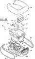
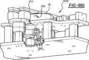
全体を通じて同様の番号が同様の又は対応する部品を指示する図面を参照すれば、一体式薬剤配送システム10が全体的に開示されている。システム10として以下に説明する一体式薬剤配送システム10は、薬剤を患者12に配送する(図19参照)。更に詳細には、システム10は、医療専門家の全体にわたって、外科処置又はいくつかの他の医療処置の後、痛み制御薬剤及びその他の薬剤を患者12に配送するのに主として使用される。図1Bに示すように、システム10は、薬剤を患者12に配送するために、導入チューブセット14と組合せて使用される。導入チューブセット14については、後で説明する。
本発明のシステム10はまた、エチレンオキシド(EtO)ガスを含むがそれに限定されない滅菌流体による完全な滅菌に適している。理想的ではないけれども、一定の液体を、システム10を滅菌するのに使用しても良い。説明の目的のためだけに、用語「薬剤」及び「滅菌」流体を全体を通じて単に流体として説明する場合もある。Referring to the drawings wherein like numerals refer to like or corresponding parts throughout, the integrated
The
主として図2A、図2B及び図3を参照すれば、システム10は、ベースハウジング16を含む。ベースハウジング16は、更に、ボトムハウジング18と、ボトムハウジング18に取付けられた中間ハウジング20と、トップハウジング22、即ち、カバーとして構成される。ハウジング18、20及び22は、好ましくは、ねじ23によって一体に取付けられている。システム10はまた、ベースハウジング16の周りに配置された薬剤リザーバ24を含む。更に詳細には、薬剤リザーバ24は、中間ハウジング20の周りに配置されている。薬剤リザーバ24は、患者12に配送すべき薬剤供給分を貯蔵する。好ましくは、薬剤リザーバ24は、可撓性であるが耐久性のあるプラスチック材料で形成される。システム10は、更に、ボトムハウジング18とトップハウジング22との間に配置されたリザーバケーシング26を含む。リザーバケーシング26は、患者12に配送すべき薬剤を保護するために、その少なくとも一部が薬剤リザーバ24を包囲している。本発明の好ましい実施形態は、薬剤を保護するために薬剤リザーバ24を包囲する2つのリザーバケーシング26を含んでいる。もちろん、リザーバケーシング26が単一の構成要素であっても良いこと、及び、薬剤を保護するに十分薬剤リザーバ24を包囲していることを理解すべきである。リザーバケーシング26は、患者12がシステム10を持ち運ぶときに特に有用である。システム10の持ち運びについては、後で説明する。
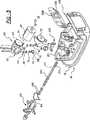
主として図2A、図3、図5及び図6A〜6Dを参照すれば、ポンプ組立体28がベースハウジング16に支持されている。特に、ポンプ組立体28は、ボトムハウジング28に取付けられている。当業者が理解しているように、ポンプ組立体28は、患者12に薬剤を配送する責任を有する。後で説明するように、ポンプ組立体28は、患者12への薬剤の不注意な配送を防止することにも役立つ。Referring primarily to FIGS. 2A, 2B and 3, the
Referring primarily to FIGS. 2A, 3, 5 and 6A-6D, a
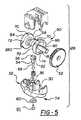
図5に最も良く示すように、ポンプ組立体28は、ポンプ入口32及びポンプ出口34を有するポンプハウジング30を含んでいる。ポンプハウジング30はまた、少なくとも1つの回り止め36を有する。少なくとも1つの回り止め36については、後で説明する。ポンプ入口32及びポンプ出口34は、患者12に薬剤を配送するために、交互に開状態と閉状態とになる。図3及び図6A〜6Dを参照すれば、ピンチバルブとも称する第1のピンチレバー38がポンプ入口32に配置され、第2のピンチレバー又はバルブ40がポンプ出口34に配置されている。第1のピンチレバー38は、ポンプ入口32を交互に開状態と閉状態にするように機能し、第2のピンチレバー40は、ポンプ出口34を交互に開状態と閉状態にするように機能する。
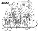
図6B及び6Cに示すように、第1のピンチレバー38は、ポンプ入口32からポンプハウジング30に流入する薬剤の流れを制御するように、開位置(図6B参照)と閉位置(図6C参照)との間を移動可能である。また、第2のピンチレバー40は、ポンプハウジング30からポンプ出口34を通る薬剤の流れを制御するように、開位置(図6C参照)と閉位置(図6B参照)との間を移動可能である。ポンプ組立体28は、更に、モーター42を含み、このモーター42は、薬剤を患者12に配送することができるように第1のピンチレバー38及び第2のピンチレバー40を移動させるために、これらのピンチレバー38、40に作動的に係合する。モーター42は、ポンプ組立体28を駆動するための駆動出力シャフト(図示せず)を含む。モーター42を含むシステム10に電力を供給する電源43が、システム10に一体化されている。好ましくは、電源は、バッテリー45及びバッテリーコンタクト47を含む。As best shown in FIG. 5, the
As shown in FIGS. 6B and 6C, the
図6Aに示すように、第1のピンチレバー38は、ポンプ入口32を閉位置に維持するように通常付勢され、第2のピンチレバー40は、ポンプ出口34を閉位置に維持するように通常付勢されている。これを達成するために、ポンプ組立体28は、少なくとも1つの付勢装置44を含んでいる。好ましくは、少なくとも1つの付勢装置44は、図面全体を通じて示しているが番号を付していない圧縮ばねである。しかしながら、少なくとも1つの付勢部材が、第1のピンチレバー38及び第2のピンチレバー40の1つ、そうでなければその両方を閉位置に通常付勢するのに適した任意の装置であっても良いことを理解すべきである。少なくとも1つの付勢部材44は、第1のピンチレバー38及び第2のピンチレバー40の少なくとも1つに係合し、モーター42と関連して、第1のピンチレバー38及び第2のピンチレバー40の少なくとも1つを閉位置に通常付勢する。このとき、もし薬剤の配送中にモーター42が故障したら、第1のピンチレバー38及び第2のピンチレバー40は閉位置に付勢され、その後、閉位置に維持され、患者12への薬剤の不注意な配送を防止する。モーター42は、少なくとも1つの付勢装置44にかかわらず、第1のピンチレバー38及び第2のピンチレバー40を開位置に移動させることが可能である。
本発明の好ましい実施形態では、少なくとも1つの付勢装置44は、第1の付勢装置46及び第2の付勢装置48を有する。第1の付勢装置46は、好ましくは圧縮ばねであり、第1のピンチレバー38に係合している。第2の付勢装置46も、好ましくは圧縮ばねであり、第2のピンチレバー40に係合している。図6Aに示すように、第1の付勢装置46及び第2の付勢装置48は、モーター42の故障中、第1のピンチレバー38及び第2のピンチレバー40を閉位置に維持し、それにより、患者12への薬剤の不注意な配送を防止する。更に詳細には、閉位置にある第1のピンチレバー38は、薬剤が引かれてポンプ入口32を通ってポンプ組立体28に入ることを防止し、閉位置にある第2のピンチレバー40は、薬剤がポンプ組立体28からポンプ出口34を通って排出されることを防止する。As shown in FIG. 6A, the
In a preferred embodiment of the present invention, the at least one
主として図5及び図6A〜6Dを参照すれば、システム10を効果的に作動させ、薬剤を患者に配送すべく第1のピンチレバー38及び第1のピンチレバー40を移動させるために、本発明のポンプ組立体28は、更に、ポンプハウジング30に支持されたカムシャフト50を含んでいる。カムシャフト50は、モーター42を第1のピンチレバー38及び第2のピンチレバー40に作動的に係合させるために、多数のギヤ52を介してモーター42にギヤ連結されている。カムシャフト50については、後でより詳細に説明する。
図5及び図7に最も良く示すように、ポンプ組立体28はまた、ポンプハウジング30内に配置されたピストン54を含んである。モーター42は、第1のピンチレバー38が開位置にあり且つ第2のピンチレバー40が閉位置にあるとき(図6B参照)、薬剤をポンプハウジング30に引込むように、ピストン54をポンプハウジング30内で移動させる。モーター42はまた、第1のピンチレバー38が閉位置にあり且つ第2のピンチレバー40が開位置にあるとき(図6C参照)、薬剤をポンプハウジング30から排出させるように、ピストン54をポンプハウジング30内で移動させる。ピストン54は、作動端部56及びポンピング端部58を有する。ダイヤフラムシール60が、ピストンキャップ61によってピストン54のポンピング端部58に固着されている。ピストン54はまた、少なくとも1つのスロット62を作動端部56に含んでいる。上述したポンプハウジング30の少なくとも1つの回り止め36が、ピストン54をモーター42及びカムシャフト50によってポンプハウジング30内で移動させたときのピストンの望まない回転を防止するために、ピストン54の作動端部56の少なくとも1つのスロット62に係合している。Referring primarily to FIG. 5 and FIGS. 6A-6D, to effectively operate the
As best shown in FIGS. 5 and 7, the
カムシャフト50は、第1の外側カム64、第2の外側カム66及び内側カム68を支持している。カムシャフト50の内側カム68は、第1の外側カム64と第2の外側カム66との間に配置されている。第1の外側カム64は、第1のピンチレバー38を開位置と閉位置との間で移動させるために、第1のピンチレバー38に係合している。第2の外側カム66は、第2のピンチレバー40を開位置と閉位置との間で移動させるために、第2のピンチレバー40に係合している。内側カム68は、ピストン54をポンプハウジング30内で移動させるために、ピストン54の作動端部56に係合している。
図5を参照すれば、第1の外側カム64及び第2の外側カム66は、それらの外周72に沿う複数のスリット70を含んでいる。これらのスリット70は、システム10の組立て及び試験中、外側カム64、66の寸法調整を確実にするのに使用される。また、第1の外側カム64及び第2の外側カム66の少なくとも一方、好ましくは、第1の外側カム64は、外側カム64、66の外周72に構成された組立用スロット74を含んでいる。この組立用スロット74は、ポンプ組立体28の組立てを容易にする。特に、この組立用スロット74は、第1のピンチレバー38及び第2のピンチレバー40をシステム10に組込んだ後、外側カム64、66を含むカムシャフト50を取付けることを容易にする。The
Referring to FIG. 5, the first
第1のピンチレバー38及び第2のピンチレバー40の各々は、カムフォロア76及びレバーガイド78を有する。レバーガイド78については、後で説明する。薬剤を患者12に配送することができるように第1のピンチレバー38及び第2のピンチレバー40を開位置と閉位置との間で交互に移動させるために、ピンチレバー38、40のカムフォロア76にカムシャフト50が係合している。更に詳細には、第1のピンチレバー38を開位置と閉位置との間で交互に移動させるために、第1のピンチレバー38のカムフォロア76に第1の外側カム64が係合し、第2のピンチレバー40を開位置と閉位置との間で交互に移動させるために、第2のピンチレバー40のカムフォロア76に第2の外側カム66が係合している。より詳細には、第1の外側カム64及び第2の外側カム66の各々は、カム内面80を有する。図6A〜6Dに示すように、第1のピンチレバー38のカムフォロア76は、第1のピンチレバー38を交互に移動させるために、第1の外側カム64のカム内面80に乗り、第2のピンチレバー40のカムフォロア76は、第2のピンチレバー40を交互に移動させるために、第2の外側カム66のカム内面80に乗る。 Each of the
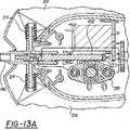
主として、図3及び図8〜10を参照すれば、システム10は、更に、ポート組立体82を含んでおり、ポート組立体82は、薬剤又は滅菌流体等の種々の流体がシステム10に流入し、その中を流れ、それから流出することを可能にする。以下、ベースハウジング16から延びているポート組立体82を、ポート82として説明する。更に詳細には、ポート82は、中間ハウジング20から延びている。ポート82は、薬剤リザーバ24及びポンプ組立体28と流体連通している。滅菌中、ポート82は、滅菌流体が薬剤リザーバ24及びポンプ組立体28に流入するためのアクセスを提供する。充填中、ポート82は、薬剤が薬剤リザーバ24及びポンプ組立体28に流入するためのアクセスを提供する。患者12への薬剤の配送中、ポート82は、薬剤を患者12に配送するためのアクセスを提供する。
特に図9及び図11A〜13Bを参照すれば、ポート82は、細長いハウジング84を含んでいる。細長いハウジング84は、近位端部86、遠位端部88及び内壁90を含み、内壁90は、近位端部86と遠位端部88との間に流体チャンバ92を構成している。細長いハウジング84の近位端部86は、流体がシステム10に流入することとそれから流出することの両方のアクセスを提供するようにシステム10から延びている。ポート82は、更に、第1の流体コネクタ94、第2の流体コネクタ96及び第3の流体コネクタ98を含んでいる。第1の流体コネクタ94を、ポート82の出口とも称し、第1の流体コネクタ94は、流体を流体チャンバ92からポンプ組立体28に流入させるように細長いハウジング84から延びている。第2の流体コネクタ96を、ポート82の入口とも称し、第2の流体コネクタ96は、流体をポンプ組立体28から流体チャンバ92に流入させるように細長いハウジング84から延びている。第3の流体コネクタ98を、薬剤リザーバ24へのアクセスとも称し、第3の流体コネクタ98は、流体が流体チャンバ92とポンプ組立体28との間を流れることを可能にするように細長いハウジング84から延びている。本発明の好ましい実施形態では、2つの第3の流体コネクタ98が設けられており、細長いハウジング84の両側から延びている。Referring primarily to FIGS. 3 and 8-10, the
With particular reference to FIGS. 9 and 11A-13B, the
主として図3、図6D及び図11A〜13Bを参照すれば、ポート82は、更に、プランジャ100を含んでいる。プランジャ100は、ポート82の流体チャンバ92内に配置され、オフ位置(図11A及び11B参照)、充填位置(図12A及び12B)及び流体配送位置(図13A及び13B)の間を移動可能である。図11A及び11Bに示すように、オフ位置では、第1、第2及び第3の流体コネクタ94、96、98は、プランジャ100によって細長いハウジング84の近位端部86から隔絶されている。その結果、ポート82の中を通る流体の流れが防止される。図12A及び12Bに示すように、充填位置では、第1の流体コネクタ94及び第3の流体コネクタ98は、細長いハウジング84の近位端部と流体連通している。その結果、細長いハウジング84の近位端部86と薬剤リザーバ24及びポンプ組立体28との間に、図12A及び12Bに示しているが番号を付していない流体流路が構成され、流体が細長いハウジング84の近位端部を通って薬剤リザーバ24及びポンプ組立体28に入って充填されるようになっている。この流体流路は、システム10の滅菌中にこの流体流路を通る滅菌流体の流れが連続しているように、ポート82と、薬剤リザーバ24と、ポンプ組立体28との間に構成される。システム10を滅菌流体で滅菌するとき、また、システム10に薬剤を充填するとき、充填位置のブランジャ100が利用される。図13A及び13Bに示すように、流体配送位置では、第1、第2及び第3の流体コネクタは、ポンプ組立体28に供給し且つ患者12に薬剤を配送するために、細長いハウジング84の近位端部86と且つ互いに流体連通する。 Referring primarily to FIGS. 3, 6D and 11A-13B, the
主として図3、図6D、図11A、図12A、図13A、図14A及び図14Bを参照すれば、システム10は、更に、ベースハウジング16内に配置されたアクチュエータ102を含んでいる。アクチュエータ102は、非係合位置と係合位置との間を移動可能である。非係合位置のアクチュエータ102については、後で説明する。図6Dに示すように、係合位置では、アクチュエータ102は、滅菌中、ポンプ入口32及びポンプ出口34を開位置に保持する、即ち、係止させるようにポンプ入口32及びポンプ出口34に作動的に係合する。ポンプ入口32及びポンプ出口34が開状態にあれば、システム10を完全に滅菌するように滅菌流体をシステム10全体にわたって浸透させることができる。即ち、滅菌流体は、システム10を完全に滅菌するために、薬剤リザーバ24、ポンプ入口32、ポンプハウジング30及びポンプ出口34に浸透することができる。
更に詳細には、アクチュエータ102は、滅菌中、ポンプ入口32及びポンプ出口34の両方を開状態に保持するように第1のピンチレバー38及び第2のピンチレバー40と相互作用する。係合位置では、アクチュエータ102は、ポンプ入口32を開状態に保持するように、第1のピンチレバー38をポンプ入口32から開位置に遠ざけ、ポンプ出口34を開状態に維持するように、第2のピンチレバー40をポンプ出口34から開位置に遠ざける。アクチュエータ102は、滅菌のために、少なくとも1つの付勢装置44の付勢にかかわらず、第1のピンチレバー38及び第2のピンチレバー40の両方を開位置に保持する。
他方、アクチュエータ102が非係合位置にあるとき、図6B及び図6Cからアクチュエータ102を省略して指示するように、アクチュエータ102は、ポンプ入口32及びポンプ出口34から作動的に離れている。薬剤を患者12に配送する必要があるときに薬剤を患者12に配送するために、アクチュエータ102は、ポンプ入口32及びポンプ出口34が交互に開状態と閉状態とになるように非係合位置にある。アクチュエータ102の非係合により、ポンプ入口32及びポンプ出口34が交互に開状態と閉状態とになることを可能にする。Mainly 3, FIG. 6D, FIG. 11A, FIG. 12A, FIG. 13A, Referring to FIGS. 14A and14 B, the
More specifically, the
On the other hand, when the
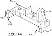
特に図14A及び図14Bを参照して、アクチュエータ102をより詳細に説明する。アクチュエータ102は、ベース部分104と、このベース部分104から延びる少なくとも1つの係合アーム106とを含んでいる。アクチュエータ102の少なくとも1つの係合アーム106は、滅菌中、ポンプ入口32及びポンプ出口34を開状態に保持するようにポンプ組立体28に作動的に係合する。更に詳細には、本発明の好ましい実施形態では、アクチュエータ102は、ベース部分104から延びる第1の係合アーム108及び第2の係合アーム110を含んでいる。好ましい実施形態では、アクチュエータ102はまた、作動アーム112を含んでいる。作動アーム112は、第1の係合アーム108と第2の係合アーム110との間をベース部分104から延びている。図面に示すように、作動アーム1112は、第1の係合アーム108と第2の係合アーム110との間をベース部分104から上方に延びている。 The
滅菌中、ポンプ入口32を開状態に保持するために、アクチュエータ102の第1の係合アーム108は、第1のピンチレバー38をポンプ入口32から遠ざかるように移動させるように第1のピンチレバー38に係合する。同様に、滅菌中、ポンプ出口34を開状態に保持するために、アクチュエータ102の第2の係合アーム110は、第2のピンチレバー40をポンプ入口出口34から遠ざかるように移動させるように第2のピンチレバー40に係合する。
滅菌後、ポンプ組立体28が作動し且つ薬剤を患者12に配送することができるように、アクチュエータ102を非係合位置に移動させることが望ましい。図6Dの矢印Aで指示するように、プランジャ100は、アクチュエータ102を係合位置から押出すように移動させ、それにより、アクチュエータ102を非係合位置に移動させる。アクチュエータ102を押出すために、プランジャ100は、作動アーム112に係合する。滅菌後、患者12に薬剤を配送すべくポンプ入口32及びポンプ出口34が交互に開状態と閉状態になるように、プランジャ100は、アクチュエータ102をポンプ組立体28との作動的な係合から押出す。更に詳細には、滅菌後、患者12に薬剤を配送するために、ブランジャ100は、アクチュエータ102を第1のピンチレバー38及び第2のピンチレバー40との係合から押出す。そのとき、第1のピンチレバー38及び第2のピンチレバー40に作動的に係合しているモーター42は、薬剤をポンプ入口32を通してポンプハウジング30内に引き且つ薬剤をポンプハウジング30からポンプ出口を通して排出するために、第1のピンチレバー38及び第2のピンチレバー40を移動させる。In order to hold the
After sterilization, it is desirable to move the
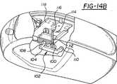
今、図14Bを参照すれば、アクチュエータ102が係合位置にあるのか非係合位置にあるのかをシステム10に指示する制御コンタクト114、好ましくは、ばね状の制御コンタクト114が、ベース部分104から遠ざかるように作動アーム112の遠位端部116に配置されている。制御コンタクト114は、アクチュエーター102が係合位置と非係合位置との間を移動するとき、アクチュエータ102の作動アーム112と相互作用する。もし制御コンタクト114を含んでいれば、アクチュエータ102が第1のピンチレバー38及び第2のピンチレバー40から離れたとき、即ち、アクチュエータ102が非係合位置にあるとき、アクチュエータ102は、電子コントローラ118を作動させるために制御コンタクト114に接触する。電子コントローラ118は、ポンプ組立体28が患者12に薬剤を配送するように作動することを可能にするために作動される。上述したように、アクチュエータ102が非係合位置にあるとき、アクチュエータ102の作動アーム112が制御コンタクト114と接触していることが好ましい。もちろん、その反対であっても良いことを理解すべきである。つまり、アクチュエータ102が係合位置にあるときにアクチュエータ102の作動アーム112が制御コンタクト114と接触しているように設計されていても良い。 Referring now to FIG. 14B, a control contact 114, preferably a spring-like control contact 114 that indicates to the
システム10は、更に、薬剤流入チューブ120及び薬剤流出チューブ122を含んでいる。薬剤流入チューブ120は、ポート82からポンプ組立体28内に、特にポンプ入口32に流れる滅菌流体用のアクセスを提供するために、ポート82とポンプ入口32との間に連結されている。薬剤流出チューブ122は、ポンプ組立体28、特にポンプ入口32からポート82に流れる滅菌流体用のアクセスを提供するために、ポンプ出口34とポート82との間に連結されている。薬剤流入チューブ120及び第1のピンチレバー38は一緒になってポンプ入口32を構成する。薬剤流出チューブ122及び第2のピンチレバー40は一緒になってポンプ出口34を構成する。
少なくとも1つの付勢装置44が、第1のピンチレバー38を閉位置に通常付勢するために第1のピンチレバー38に係合しているとき、薬剤流入チューブ120は挟まれる。そのとき、ポンプ入口32は、閉状態に維持される。同様に、少なくとも1つの付勢装置44が、第2のピンチレバー40を閉位置に通常付勢するために第2のピンチレバー40に係合しているとき、薬剤流出チューブ122は挟まれる。そのとき、ポンプ出口34は、閉状態に維持される。しかしながら、図6Dに示すように、滅菌中、アクチュエータ102が係合位置にあるとき、アクチュエータ42は、ポンプ入口32が開状態になったままにすべく第1のピンチレバー38を薬剤流入チューブ120から遠ざけるように移動させるために、少なくとも1つの付勢装置44の付勢に打ち勝ち、しかも、ポンプ出口34が開状態になったままにすべく第2のピンチレバー40を薬剤流出チューブ122から遠ざけるように移動させるために、少なくとも1つの付勢装置44の付勢に打ち勝つ。The
When at least one
特に図3及び図8〜10を参照して、ポート82及びプランジャ100を詳細に説明する。プランジャ100は、長さL及び外周Cを含み、更に、プランジャ100の長さLに沿って且つ外周Cの周りに配置された座124を含んでいる。座124は、ポート82の細長いハウジング84の流体チャンバ92を分けるために、プランジャ100の外周Cから外方に、細長いハウジング84の内壁90まで延びている。番号を付していない流路が、座124の各々と細長いハウジング84の内壁90との間に構成される。これらの流路は、ポート82内の流体の流れを制御する。座124は、流体チャンバ92を適当に分けるのが良いけれども、流路を互いにシールするのを補助するために、座124の各々の周りにシール126が配置されることが好ましい。図面に示す最も好ましい実施形態では、これらのシールは、Oリングである。少なくとも1つの漏れリブ128の少なくとも一部分が、細長いハウジング84の内壁90に沿って延びている。少なくとも1つの漏れリブ128は、プランジャ100が充填位置にあるとき、少なくとも1つの座126が選択的に漏れを生じさせるようにする。図面に示すように、細長いハウジング84の内壁90に沿って延びる2つの漏れリブがあることが好ましい。 The
図11A〜図13Bに示すように、プランジャ100は、その少なくとも一部分が中空である。この場合、プランジャ100は、その中を且つ座124の間に延びる内部流体ボア130を有する。プランジャ100は、更に、アクセス端部132と、プランジャ作動端部134とを含んでいる。好ましくは圧縮ばねであるプランジャ付勢装置136が、プランジャ100をオフ位置に付勢するために、プランジャ100の作動端部の周りに配置されている。内部流体ボア130は、流体が内部流体ボア130に流れ込んだりそこから流れ出たりするアクセス端部132から、プランジャ作動端部134に向かって延びている。内部流体ボア130は、流れが内部流体ボア130に流れ込んだりそこから流れ出たりするように流路の1つと流体連通している流体ダクト138を含んでいる。
本発明の最も好ましい実施形態では、複数の座124は、更に、第1の座140、第2の座142、第3の座144及び第4の座146として構成される。第1の座140は、プランジャ100のアクセス端部132の方に配置されている。第4の座146は、プランジャ100のプランジャ作動端部134の方に配置されている。第2の座142及び第3の座144は、第1の座140と第4の座146との間に連続的に配置されている。この実施形態では、流路は、更に、第1の流路148、第2の流路150及び第3の流路152として構成される。第1の流路148は、第1の座140、第2の座142及び内壁90の間に構成される。第2の流路150は、第2の座142、第3の座144及び内壁90の間に構成される。第3の流路152は、第3の座144、第4の座146及び内壁90の間に構成される。As shown in FIGS. 11A to 13B, at least a part of the
In the most preferred embodiment of the present invention, the plurality of
第1の流路148をプランジャ100のアクセス端部132からシールするための第1のシール154が、第1の座140の周りに配置される。第1の流路148及び第2の流路150を互いからシールするための第2のシール156が、第2の座142の周りに配置される。第2の流路150及び第3の流路152を互いからシールするための第3のシール158が、第3の座144の周りに配置される。第3の流路152をプランジャ100のプランジャ作動端部134からシールするための第4のシール160が、第4の座146の周りに配置される。この実施形態では、少なくとも1つの漏れリブ128は、近位端部86から遠位端部88に向かって細長いハウジング84の内壁90に沿って延び、プランジャ100が充填位置にあるときに第1の座154だけが選択的に漏れるように第1のシール154をわずかに越えている。
この最も好ましい実施形態では、内部流体ボア130は、プランジャ100内をアクセス端部132から第3の座144まで延びている。このとき、流体ダクト138は、第2の座142、第3の座144及び内壁90の間に構成された第2の流路150と流体的に連通し、その結果、流体は、第2の流路150のところで、内部流体ボア130に流れ込んだり、それから流れ出ることができる。A
In this most preferred embodiment, the internal fluid bore 130 extends within the
プランジャ100のオフ位置、充填位置、及び流体配送位置を、4つの座140、142、144、146、3つの流路148、150、152及び4つのシール154、156、158、160を有する最も好ましい実施形態に関連させて説明する。図11A及び図11Bを参照すれば、プランジャ100がオフ位置にあるとき、第1の流体コネクタ94、第2の流体コネクタ96、及び第3の流体コネクタ98は、第1の座140、第2の座142及び第3の座144によって、細長いハウジング84の近位端部86及びプランジャ100のアクセス端部132から隔絶している。このオフ位置では、第1の流体コネクタ94及び第3の流体コネクタ98は、第3の流路152と整列している。 The
図12A及び図12Bを参照すれば、プランジャ100が充填位置にあるとき、第1の流体コネクタ94及び第3の流体コネクタ98は、第2の流路150及び内部流体ボア130の流体ダクト138を通じて、細長いハウジング84の近位端部86及びプランジャ100のアクセス端部132と流体的に連通している。この充填位置では、第1の流体コネクタ94及び第3の流体コネクタ98は、第2の流路150と整列している。この時、流体をプランジャ100のアクセス端部132から内部流体ボア130及び流体ダクト138を通して薬剤リザーバ24及びポンプ組立体28の中に充填することができる。充填位置では、第2の流体コネクタ96は、第3の座144及び第4の座146によって、細長いハウジング84の近位端部86、プランジャ100のアクセス端部132、第1の流体コネクタ94及び第3の流体コネクタ98から隔絶されている。 Referring to FIGS. 12A and 12B, when the
図13A及び図13Bを参照すれば、プランジャ100が流体配送位置にあるとき、第2の流体コネクタ96は、第2の流路150及び内部流体ボア130の流体ダクト138を通じて、細長いハウジング84の近位端部86及びプランジャ100のアクセス端部132と流体的に連通している。流体配送位置では、薬剤がポンプ組立体28から患者12に配送される。流体配送位置では、第1の流体コネクタ94及び第3の流体コネクタ98は、第1の座140及び第2の座142によって、細長いハウジング84の近位端部86及びプランジャ100のアクセス端部132から隔絶している。しかしながら、流体、即ち、薬剤をポンプ組立体28に供給するために、第1の流体コネクタ94及び第3の流体コネクタ98は、第1の流路148を通じて、薬剤リザーバ24と流体的に連通している。即ち、流体配送位置では、第1の流体コネクタ94及び第3の流体コネクタ98は、第1の流路148と整列している。 Referring to FIGS. 13A and 13B, when the
プランジャ100を、薬剤リザーバ24及びポンプ組立体28を充填する充填位置に自動的に移動させるために、図12Bに全体的に162で示す流体充填装置がハウジングの近位端部86に係合している。システム10を滅菌するならば、流体充填装置162は、好ましくは、滅菌流体を薬剤リザーバ24及びポンプ組立体28の中に行き渡らせることを可能にする充填位置にプランジャ100を移動させる流体即ち滅菌キャップ164であり、図12Bでは、流体即ち滅菌キャップ164をシステム10から取外して示している。設計によって、流体キャップ164は、プランジャ100を充填位置に自動的に移動させる。従って、システム10が、滅菌流体、好ましくは、EtOガスを充填したチャンバーに導入されるとき、滅菌流体が流体キャップ164から細長いハウジング84の近位端部86及びプランジャ100のアクセス端部132を通り、内部流体ボア130及び流体ダクト138を通って第2流路150に流れ込み又はしみ込み(seep)、次いで、第3の流体コネクタ98から薬剤リザーバ24に流れ込み、第1の流体コネクタ94からポンプ組立体28に流れ込む。
システム10を薬剤で充填するならば、流体充填装置162は、好ましくは、薬剤リザーバ24及びポンプ組立体28を充填する充填位置にプランジャ100を移動させるシリンジ166である。図12Bでは、システム10に取付けて示しているシリンジ166は、プランジャ100のアクセス端部132に係合し、設計によって、内部流体ボア130を通して薬剤リザーバ24及びポンプ組立体28を充填する充填位置にプランジャ100を自動的に移動させる。従って、システム10を充填するとき、シリンジ166は、細長いハウジング84の近位端部86及びプランジャ100のアクセス端部132と相互作用し、シリンジプランジャを引込めたとき、薬剤が内部流体ボア130及び流体ダクト138を通って第2の流路150に流れ込み、次いで、第3の流体コネクタ98から薬剤リザーバ24に流れ込み、第1の流体コネクタ94からポンプ組立体28に流れ込む。To automatically move the
If the
薬剤を患者12に配送するために、システム10は、導入チューブセット14と組合せて使用される。図1Aに戻ってそれを参照すれば、導入チューブセット14は、流体端部168及び患者端部170を含んでいる。チューブセット14の流体端部168は、薬剤を患者12に配送する流体配送位置にプランジャ100を自動的に移動させるように、配送コネクタ172を介して細長いハウジング84の近位端部86及びプランジャ100のアクセス端部132に係合している。従って、図13A及び図13Bに示すように、ポンプ組立体28を作動させたとき、薬剤は薬剤リザーバ24から第3の流体コネクタ98を通ってポート82即ち第1の流路148に流れ込み、次いで、第1の流体コネクタ94からポンプ入口32に流れ込む。次いで、薬剤は、ポンプ組立体28から排出され、ポンプ出口34、第2流体コネクタ96を通ってポート82即ち第2の流路150に流れ込み、次いで、プランジャ100の流体ダクト138及び内部流体ボア130を通って、プランジャ100のアクセス端部132から導入チューブセット14の流体端部168に流れる。薬剤は、そこから導入チューブセット14の中を通って患者端部170から患者12に流れる。 The
戻って図4を参照すれば、システム10は、更に、電子コントローラ118を含んでいる。電子コントローラ118は、患者12に配送すべき薬剤の量を制御する。電子コントローラ118は、ベースハウジング16、特に、そのトップハウジング22に取付けられている。更に、電子コントロローラ118は、滅菌中、ベースハウジング16に取付けられたままであり、その結果、すべての機械的構成要素、薬剤リザーバ24及び電子コントローラ118を含む全体システム10が同時的に滅菌される。電子ディスプレイ174及び少なくとも1つの制御ボタン176がベースハウジング16に取付けられている。電子ディスプレイ174及び制御ボタン176は、患者12に配送すべき薬剤の量を制御するように電子コントローラ118と相互作用する。電子コントローラ118と同様、滅菌中、電子ディスプレイ174及び制御ボタン176もベースハウジング16に取付けられたままである。 Returning to FIG. 4, the
本発明は、また、図15A及び図15Bに全体的に178で示す遮断検出装置を有する。遮断検出装置178は、患者12への薬剤の流れの遮断を検出する。遮断検出装置178は、ベースハウジング16、薬剤リザーバ24、ポート82、ポンプ組立体28、薬剤流出チューブ122及び電子コントローラ118で構成される。遮断検出装置178は、また、後で説明する検出フィルム180を含んでいる。
遮断検出装置178では、電子コントローラ118は、薬剤流出チューブ122に隣接してベースハウジング16に取付けられている。薬剤流出チューブ122は、ベースハウジング16に取付けられており、上述のように、ポンプ組立体28からポート82に流入し且つ患者12に流れる薬剤用のアクセスを提供するために、流入ポンプ組立体28とポート82との間に連結される。薬剤流出チューブ122は、通常状態(図15A参照)と拡張状態(図15B参照)との間を収縮且つ拡張可能な直径を有する。薬剤流出チューブ122の直径は、薬剤リザーバ24からポンプ組立体28を通ってポート82及び患者12に流れる薬剤の流れによって生じる圧力変化に応答して、収縮したり拡張したりする。The present invention also includes an interrupt detection device, generally designated 178 in FIGS. 15A and 15B. The
In the
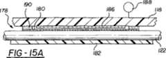
図面に示すように、薬剤流出チューブ122は、支持プラットフォーム182を介してベースハウジング16に取付けられている。即ち、支持プラットフォーム182は、薬剤流出チューブ122をベースハウジング16の上に支持するようにベースハウジング16に取付けられている。支持プラットフォーム182は、少なくとも1つのチューブスロット184を含んでいる。少なくとも1つのチューブスロット184は、薬剤流出チューブ122の直径を収容する。薬剤流出チューブ122は、その直径の、番号を付していない少なくとも一部分が検出フィルム180に晒されるようにチューブスロット184内に取付けられている。
検出フィルム180は、電子コントローラ118と薬剤出口チューブ122との間に配置されている。検出フィルム180は、図15Aに示すように、薬剤流出チューブ122の直径が通常の状態にあるとき、薬剤流出チューブ122と接触し且つ電子コントローラ118と間隔を隔てたままである。他方、図15Bに示すように、患者12への薬剤の流れの遮断により生じた上昇圧力に応答して、薬剤流出チューブ122の直径が拡張状態にあるとき、検出フィルム180は、電子コントローラ118を作動させるために、薬剤流出チューブ122と接触し且つ電子コントローラ118と接触する。更に詳細には、電子スイッチ186が電子コントローラ118と検出フィルム180との間の電子コントローラ118内に埋設されることが好ましい。薬剤流出チューブ122の直径が拡張状態にあるとき、検出フィルム180は、それが電子スイッチ186に接触することによって、電子コントローラ118を作動させるように電子コントローラ118と相互作用する。As shown in the drawings, the
The
薬剤流出チューブ122の直径が拡張状態にあるときに電子コントローラ118を作動させるために、検出フィルム180が導電性であることが好ましい。電子コントローラ118は、いったん検出フィルム180によって作動されると、ポンプ組立体28を非作動状態にして、薬剤流出チューブ122の直径が拡張状態にあるときの患者12への薬剤の配送を防止する。ポンプ組立体28の非作動により、更なる遮断及び更なる圧力上昇を防止する。薬剤流出チューブ122内に遮断があることを間違いなく確保するために、薬剤流出チューブ122の直径がポンプ組立体28の少なくとも1サイクルよりも長い間拡張状態にあるときにだけ、電子コントローラ118、従って、ポンプ組立体28を非作動にすることが最も好ましい。この追加の方法は、薬剤流出チューブ122が本当に遮断されていないとき、の間違った読み及びポンプ組立体28の非作動を回避する。
加えて、電子コントローラ118は、いったん検出フィルム180によって作動されると、図面に概略的に示すアラーム188を作動させるのが良い。アラーム188は、可聴であっても良いし、電子ディスプレイ上に視覚的に表示させても良いし、その両方であっても良い。アラーム188は、患者12への薬剤の流れの遮断による遮断を指示する。In order to activate the
In addition,
検出フィルム180が電子コントローラ118に取付けられることが好ましい。検出フィルム180が電子コントローラ118に取付けられていなくても、薬剤流出チューブ122の直径が通常の状態にあるとき、検出フィルム180の番号を付していない一部分は、電子コントローラ118から少なくとも部分的に間隔を隔てたままである。検出フィルム180は、接着剤層190で電子コントローラ118に取付けられている。接着剤層190はまた、薬剤流出チューブ122の直径が通常の状態にあるとき、検出フィルム180、特に、その一部分が電子コントローラ118から間隔を隔てるのに必要な厚さを提供する。検出フィルム180の一部分は、薬剤流出チューブ122の上昇圧力に応答して、薬剤流出チューブ122の直径が拡張状態にあるとき、電子コントローラ118を作動させるように電子コントローラ118に接触している。 A
遮断検出システム178の変形実施形態を図17に示す。この変形実施形態では、検出フィルム180が削除され、コーティング192が設けられている。コーティング192は、薬剤流出チューブ122に塗布されている。コーティング192は、患者12への薬剤の流れの遮断により生じた上昇圧力に応答して、薬剤流出チューブ122の直径が拡張状態にあるとき、電子コントローラ118を作動させる。検出フィルム180と同様、コーティング192が導電性であることが好ましい。コーティング192が存在する場合、コーティング192が導電性カーボンで形成されることが最も好ましい。しかしながら、導電性が付与された他のコーティングを使用しても良い。
遮断検出システム178のこの変形実施形態のその他の特徴は、大部分、遮断検出システム178の好ましい実施形態において上述した特徴と同一である。注目すべきことは、この変形実施形態では、コーティング192の少なくとも一部分がチューブスロット184を越えて露出するように、薬剤流出チューブ122がチューブスロット184の中に取付けられていることである。A modified embodiment of the
Other features of this modified embodiment of the
本発明はまた、図16A及び図16Bに全体的に194で示す空検出システム194を提供する。空検出システム194は、いつ薬剤の供給源が使い果たされたかを決定する。空検出システム194は、ベースハウジング16と、患者12に配送すべき薬剤の供給源を貯蔵するためのリザーバ24と、ポート82と、ポンプ組立体28と、薬剤流入チューブ120と、電子コントローラ118とを有する。遮断検出システム178と同様、空検出システム194の好ましい実施形態もまた、参照番号180で示す検出フィルムを含んでおり、この検出フィルム180については後で説明する。
空検出システム194では、電子コントローラ118は、薬剤流入チューブ120に隣接してベースハウジング16に取付けられている。薬剤流入チューブ120は、ベースハウジング16に取付けられ、上述したように、リザーバ24からポンプ組立体28に又は患者12に流れる薬剤のためのアクセスを提供するために、リザーバ24とポンプ組立体28との間に連結されている。薬剤流入チューブ120は、通常状態(図16A参照)と縮み状態(図16B参照)との間を収縮且つ拡張可能な直径を有している。薬剤流入チューブ120は、縮み状態に収縮し、縮み状態から拡張状態に拡張する。薬剤流入チューブ120の直径は、リザーバ24からポンプ組立体28の中を通って患者12に流れる薬剤の流れの欠如によって生じる圧力変化に応答して、収縮したり拡張したりする。The present invention also provides an
In the
図面に示すように、薬剤流入チューブ120は、支持プラットフォーム182を介してベースハウジング16に取付けられている。即ち、支持プラットフォーム182は、薬剤流入チューブ120をベースハウジング16に支持するためにベースハウジング16に取付けられている。支持プラットフォーム182は、少なくとも1つのチューブスロット184を含んでいる。少なくとも1つのチューブスロット184は、薬剤流入チューブ120の直径を収容する。薬剤流入チューブ120は、その直径の一部分が検出フィルム180に晒されるようにチューブスロット184内に取付けられている。
検出フィルム180は、電子コントローラ118と薬剤流入チューブ120との間に配置されている。図16Aに示すように、検出フィルム180は、薬剤流入チューブ120の直径が通常状態にあるときに電子コントローラ118を作動させるために、薬剤流入チューブ120に接触し且つ電子コントローラ118に接触している。他方、図16Bに示すように、検出フィルム180は、薬剤の供給源が使い果たされることによって生じた薬剤流れの欠如に応答して薬剤流入チューブ120の直径が縮み状態にあるときに電子コントローラ118を非作動にするために、電子コントローラ118から間隔を隔てるようになる。
電子スイッチ186が電子コントローラ118及び検出フィルム180との間の電子コントローラ118に埋め込まれていることが好ましい。検出フィルム180は、薬剤流入チューブ120の直径が通常状態にあるとき、電子コントローラ118を作動させるように電子スイッチ186に接触し、薬剤流入チューブ120の直径が縮み状態にあるとき、電子コントローラ118を非作動にするように電子スイッチ186から間隔を隔てるようになる。As shown in the drawings, the
The
An
図4に最も良く示すように、更に詳細には、検出フィルム180は、フィルムベース部分196及び片持ち部分198を含んでいる。検出フィルム180のフィルムベース部分196は、電子スイッチ186から離れて電子コントローラ118に取付けられている。検出フィルム180の片持ち部分198は、電子スイッチ186に隣接している。更に詳細には、片持ち部分198は、薬剤流入チューブ120が通常状態にあるときに電子スイッチ186に接触するように、フィルムベース部分104から延びている。検出フィルム180の片持ち部分198こそが、薬剤流入チューブ120が縮み状態にあるときに電子コントローラ118を非作動にするために、電子コントローラ118から間隔を隔てるようになる。薬剤流入チューブ120が通常状態にあるときに電子コントローラ118を作動させるために、検出フィルム180、特に、その片持ち部分198が導電性であることが好ましい。好ましくは、検出フィルム180は、接着剤層190を有する電子コントローラ118に取付けられている。もちろん、検出フィルム180のフィルムベース部分196こそが電子コントローラ118に直接取付けられている。検出フィルム180の片持ち部分198は、薬剤流入チューブ120の直径が縮み状態にあるときに検出フィルム180の片持ち部分198が電子コントローラ118から間隔を隔てるようになることができるように、電子コントローラ118に直接取付けられていない、即ち、その他の方法で接着されていない。 In more detail, as best shown in FIG. 4, the
いったん検出フィルム180が電子コントローラ118から間隔を隔てるようになれば、即ち、薬剤流入チューブ120の直径が縮み状態にあるとき、ポンプ組立体28と相互作用する電子コントローラ118の一部分は、ポンプ組立体が非作動にされるように非作動にされる。薬剤の供給源が使い果たされたことを決定した後のポンプ組立体28の非作動により、システム内へのエアの堆積を防止する。薬剤の供給源が使い果たされたことを間違いなく確保するために、薬剤流入チューブ120の直径がポンプ組立て128の少なくとも1サイクルよりも長い間縮み状態にあるときにだけ、電子コントローラ118、従って、ポンプ組立体28が非作動にされることが最も好ましい。この追加の方法により、薬剤の供給源が本当に使い果たされていないときの間違った読み及びポンプ組立体28の非作動を回避する。
加えて、ポンプ組立体28と相互作用する電子コントローラ118の一部分の非作動により、電子コントローラ118がアラーム188を作動させるようにしても良い。可聴の及び/又は電子ディスプレイ174に視覚的に表示されるアラーム188は、患者12への薬剤の流れの欠如により薬剤流入チューブ120の直径が縮み状態にあるとき、薬剤の流れの欠如を指示する。Once the
In addition, deactivation of a portion of
空検出システム194の変形実施形態を図17に示す。この変形実施形態では、検出フィルム180が削除され、コーティング192が設けられている。コーティング192は、薬剤流入チューブ120に塗布されている。コーティング192は、薬剤流入チューブ120の直径が通常状態にあるときに電子コントローラを作動させるために、電子コントローラ118に接触している。他方、薬剤の供給源が使い果たされることによって生じた薬剤の流れの欠如に応答して、薬剤流入チューブ120の直径が縮み状態にあるとき、コーティング192は、電子コントローラ118を非作動にするために電子コントローラ118から間隔を隔てるようになる。検出フィルム180と同様、コーティング192は、好ましくは、導電性である。コーティング192がある場合、コーティング192が導電性カーボンで形成されることが最も好ましい。しかしながら、導電性が付与された他のコーティングを使用しても良い。
空検出システム194のこの変形実施形態のその他の特徴は、大部分、空検出システム194の好ましい実施形態において上述した特徴と同一である。注目すべきことは、この変形実施形態では、コーティング192の少なくとも一部分がチューブスロット184を越えて露出するように、薬剤流入チューブ120がチューブスロット184の中に取付けられていることである。A modified embodiment of the
Other features of this alternative embodiment of
図1B、図6A〜6D、図18A及び図18Bを参照すれば、本発明のシステム10の組立て後、システム10を、試験器具200を用いて試験することができる。システム10は、その種々の作動を確認するために、組立て後、出荷及び外科医、患者等による使用の前に試験される。好ましい実施形態では、システム10を試験するために、システム10を試験器具200に取付ける。システム10の組立て後に確認されるシステム10の作動の1つは、ポンプ組立体28の作動である。
これらの作動を確認するために、システム10は、少なくとも1つの試験アクセスポート202を含んでいる。少なくとも1つの試験アクセスポート202は、ベースハウジング16内に構成され、ポンプ入口32、ポンプ出口34及びアクチュエータ102の少なくとも1つと整列している。好ましくは、少なくとも1つの試験アクセスポート202は、ポンプ入口32、ポンプ出口34及びアクチュエータ102のすべてと整列している。少なくとも1つの試験アクセスポート202は、アクチュエータ102を非係合位置と係合位置との間で移動させるため、試験器具200用のアクセスを提供する。もし少なくとも1つの試験アクセスポート202がポンプ入口32及びポンプ出口34と整列していないならば、少なくとも1つの試験アクセスポート202は、第1のピンチレバー38及び第2のピンチレバー40と整列する。また、アクチュエータ102との整列について、更に詳細には、少なくとも1つの試験アクセスポート202は、アクチュエータ102の少なくとも1つの係合アーム106と整列している。これは、アクチュエータ102を非係合位置と係合位置との間で移動させるため、試験器具200用のアクセスを提供する。Referring to FIGS. 1B, 6A-6D, 18A and 18B, after assembly of the
To confirm these operations, the
システム10は、好ましくは、第1のピンチレバー38及び第2のピンチレバー40は開位置にあり且つ薬剤流入チューブ120及び薬剤流出チューブ122の弾性が弱められ且つ寿命短くならないように、係合位置でアクチュエータ102と組立てられる。少なくとも1つの試験アクセスポート202が、アクチュエータ102を非係合位置と係合位置との間で移動させるため、試験器具200用のアクセスを提供するので、アクチュエータ102を分離するために、即ち、アクチュエータ102を非係合位置に移動させるために、試験器具200を少なくとも1つの試験アクセスポート202に挿入することができる。同様に、ポンプ入口32及びポンプ出口34は、システム10の組立て後且つ試験中、交互に開状態と閉状態とになる。
少なくとも1つの試験アクセスポートはまた、システム10を試験して、システム10を滅菌のために準備した後、ポンプ入口32及びポンプ出口34を開状態に保持することができるように、試験器具200のためのアクセスを提供する。即ち、システム10を試験した後、アクチュエータ102を非係合位置から係合位置に戻し、システム10を滅菌のために準備する。係合位置では、第1のピンチレバー38及び第2のピンチレバー40を開状態に保持する。The
The at least one test access port also allows the
好ましい実施形態では、少なくとも1つの試験アクセスポート202は、第1の試験アクセスポート204、第2の試験アクセスポート206及び第3の試験アクセスポート208として更に構成される。第1の試験アクセスポート204は、ポンプ入口32と整列する。第2の試験アクセスポート206は、ポンプ出口34と整列する。第3の試験アクセスポート208は、アクチュエータ102を係合位置に移動させるための試験器具200へのアクセスを提供するために、アクチュエータ102と整列する。更に詳細には、第1の試験アクセスポート204は、試験器具200が第1のピンチレバー38に係合するように第1のピンチレバー38と整列する。いったん第1の試験アクセスポート204の内側になれば、試験器具200は、第1のピンチレバー38をポンプ入口32から無理やり遠ざけ、ポンプ入口32を強制的に開状態にする。同様に、第2の試験アクセスポート206は、試験器具200が第2のピンチレバー40に係合するように第2のピンチレバー40と整列する。いったん第2の試験アクセスポート206の内側になれば、試験器具200は、第2のピンチレバー40をポンプ出口34から無理やり遠ざけ、ポンプ出口入34を強制的に開状態にする。第1のピンチレバー38及び第2のピンチレバー40は、各ピンチレバー38、40のカムフォロア76に対向するレバーガイド78を含んでいる。第1のピンチレバー38及び第2のピンチレバー40を移動させるために、第1の試験アクセスポート204及び第2の試験アクセスポート206への挿入時、試験器具200は、レバーガイド78に係合する。試験器具200が第1のピンチレバー38及び第2のピンチレバー40をそれぞれ、強制的にポンプ入口32及びポンプ出口34から遠ざけた後、試験器具200を第3の試験アクセスポート208に導入し、アクチュエータ102を係合位置に移動させ、第1のピンチレバー38及び第2のピンチレバー40に係合し、それを開位置に保持し、その結果、システム10は、今、滅菌の準備が整っている。試験器具200が、試験アクセスポート204、206、208に導入され且つ全体的に210で指示する雄プロング含んでいることを当業者は理解すべきである。 In the preferred embodiment, the at least one
システム10は、更に、ベースハウジング16内に構成された少なくとも1つのコントローラアクセスポート212を含んでいる。好ましい実施形態では、少なくとも1つのコントローラアクセスポート212は、トップハウジング22即ちカバー内に構成される。少なくとも1つのコントローラアクセスポート212は、第2の試験器具214のためのアクセスを提供するために、電子コントローラ118と整列する。図面に示すように、第2の試験器具214及び試験器具200が単一の構成要素であっても良いことを理解すべきである。第2の試験器具214により、電子コントローラ118がモーター42を作動させるようにし、システム10の組立て後及びその試験中、ポンプ入口32及びポンプ出口34を交互に開状態と閉状態とにするようにモーター42が動力を受ける。第2の試験器具214はまた、好ましくは、コントローラアクセスポート212に導入される雄プロングを含んでいる。 The
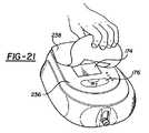
主として図2A〜図3、図19及び図20を参照すれば、本発明のシステム10はまた、患者12が持ち運ぶのに適当である。患者12が歩行したままでいられるようにシステム10の持ち運びを容易にするために、患者12がシステム10を持ち運ぶための持ち運びストラップ216がベースハウジング16内に取付けられる。一体式収容キャビティ218がベースハウジング16内に構成される。持ち運びストラップ216は、その少なくとも一部分が一体式収容キャビティ218内に配置されている。持ち運びストラップ216は、その少なくとも一部分が一体式収容キャビティ218から延びている。システム10を持ち運ぶために患者12と相互作用する。
システム10は、更に、複数のキャビティ壁を含んでいる。キャビティ壁は、ボトムハウジング18から延び、ボトムハウジング18とトップハウジング22との間に一体式収容キャビティ218を構成する。特に図20を参照すれば、キャビティ壁は、更に、前壁220、後壁222、前壁220及び後壁222を支持し且つ一体式収容キャビティ218を構成するために前壁220と後壁222との間を延びる第1の壁及び第2の壁224として構成される。少なくとも1つのストラップスロット226が、持ち運びストラップの番号を付していない少なくとも一部分が一体式収容キャビティからストラップスロット226を通って延びるように、前壁220内に構成される。患者12は、望むとき、持ち運びストラップ216の一部分にアクセスすることができる。Referring primarily to FIGS. 2A-3, 19 and 20, the
The
持ち運びストラップ216と相互作用する際、患者12は、単に、持ち運びストラップ216の一定の長さ部分を一体式収容キャビティ218から引くように持ち運びストラップ216の一部分を操作する、即ち、掴んでいる。次いで、図19に特に示すように、この一定の長さ部分を患者12の頭の周りでループにする。好ましい実施形態では、持ち運びストラップ216は、患者12が一定の長さ部分を一体式収容キャビティ218から引いた後、一体式収容キャビティ218の中に引っ込み可能である。システム10は、更に、持ち運びストラップ216を患者12の全体寸法に合わせるのに調節可能にするように持ち運びストラップ216の両端に連結されたクリップ228を含んでいる。図19に示す本発明の最も好ましい実施形態では、持ち運びストラップ216は、更に、シヨルダーストラップとして構成されている。シヨルダーストラップは、システム10を持ち運ぶために、患者12の肩に掛っている。
また、図1Bに特に示すように、システム10は、更に、ベースハウジング16の外面材232から延びるシステム取付けクリップ230を含んでいるのが良い。システム取付けクリップ230は、患者12のベルト234に取付けられるのが良い。もちろん、システム取付けクリップ230がベルト234用のクリップに限定されないと理解すべきである。その代わりに、システムクリップ230は、シャツ、ポケット等に取付けられても良い。In interacting with the carrying
Also, as specifically shown in FIG. 1B, the
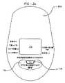
図2B及び図21〜24を参照すれば、本発明は、更に、システム10の制御方法を提供する。この方法は、外科医又はその他の医療専門家と患者12の両方に便利であるように設計されている。第2セットの説明書き即ち指示を有する患者ラベル236が、システム10に取付けられ、好ましくは、接着されている。第1セットの説明書き即ち指示を有する取外し可能な上置きラベル238が、その少なくとも一部分が患者ラベル236を覆うように、患者ラベル236に取付けられ、好ましくは、接着される。
本方法は、取外し可能な上置きラベル238の第1セットの説明書きに従って、薬剤の量を選択するステップを含んでいる。医療専門家は、薬剤の量を選択する。そのとき、第1セットの説明書きは、医療専門家が容易に理解できるようになっている。典型的には、薬剤の量は、薬剤の流量を選択することによって選択される。限定するわけではないが、薬剤1回分の量、薬物即ち薬剤濃度等のその他のパラメーターを選択しても良い。
選択するステップを通して、医療専門家及び/又は患者12は、電子ディスプレイ174とインターフェースし、自らの選択を見る。更に詳細には、電子ディスプレイ174は、医療専門家及び患者12が読み取り可能な出力を提供する。電子ディスプレイ174に表示された読み取り可能な出力は、取外し可能な上置きラベル238及び患者ラベル236と相互に関連している。即ち、読み取り可能な出力は、第1セットの指示及び第2セットの指示に相互に関連している。第1の読み取り可能な出力を、電子ディスプレイ174に提供する。取外し可能な上置きラベル238が表示されているとき、第1の読み取り可能な出力を第1セットの説明書きとリンクさせる。同様に、第2の読み取り可能な出力が電子ディスプレイ174に提供される。システム10をロックした後、第2の読み取り可能な出力を第2セットの説明書きとリンクさせる。システム10をロックさせることを、以下に説明する。2B and FIGS. 21-24, the present invention further provides a method for controlling the
The method includes selecting the amount of drug according to the first set of instructions for the removable
Through the selection step, the medical professional and / or
薬剤の量を選択した後、患者12に配送すべき薬剤の選択量を変更することができないようにシステム10をロックする。医療専門家が彼又は彼女の選択に満足した後、医療専門家は、取外し可能な上置きラベル238の第1セットの説明書きの「ロック」部分を押し下げ、システム10をロックさせる。
いったんシステム10をロックさせたら、図21に示すように、医療専門家又は患者12のいずれかが、取外し可能な上置きラベル238を取外して患者ラベル236を露出させることができる。これを達成するために、使用者、即ち医療専門家又は患者12のいずれかは、単に、取外し可能な上置きラベル238を引張って患者ラベル236から外す。これにより、元々取外し可能な上置きラベル238の下に隠されていた制御ボタン176を露出させる。次いで、システム10を患者ラベル236の第2セットの説明書きに従って操作する。第2セットの説明書きは、患者12が容易に理解できるようになっている。いったんシステム10をロックしたら、システム10は、患者12が使用するのに便利であるように設計されている。
システム10をロックさせたとき、制御ボタン176の機能特性を変更する。そのとき、取外し可能な上置きラベル238がシステム10の上に見えているときの制御ボタン176の機能特性は、患者ラベル236がシステム10の上に見えているときと比べて異なっている。換言すれば、医療専門家が取外し可能な上置きラベル238を介してシステム10と相互作用するときの制御ボタン176の機能特性は、患者12が患者ラベル236を介してシステム10と相互作用するときと比べて異なっている。取外し可能な上置きラベル238がシステム10の上に見えているとき、制御ボタン176は、少なくとも3つの機能を有する。他方、システム10をロックさせ且つ患者ラベル236をシステム10の上に見えるようにした後、制御ボタン176の機能特性は、少なくとも3つの機能から2つの機能に変換される。After selecting the amount of drug, the
Once the
When the
システム10を操作する際、必要ならば、システム10を非作動にして、患者12への薬剤の配送を停止させるのが良い。システム10を非作動にするために、患者12は、患者ラベル236の第2セット説明書きに応答して、今は2機能になっている制御ボタン176の「ON/OFF(入/切)」部分を押し下げる。システム10を非作動にしたら、患者12は、制御ボタン176を使用して、システム10を作動させ、患者12への薬剤の配送を再開しても良い。これを達成するために、患者12は、再度、制御ボタン176の「ON/OFF」部分を押し下げる。
変形例として、システム10を操作する際、患者12は、薬剤の選択された量に対する薬剤の追加の量を要求しても良く、薬物1回分の量が違反でなければ、患者12は、薬剤の追加の量を受け取る。選択された量に対する薬剤の追加の量を要求するために、患者12は、制御ボタン176を作動させる。When operating the
Alternatively, when operating the
特に図25を参照すれば、本発明の実施形態によるシステム10用の制御システム240が示されている。制御システム240は、電子コントローラ118と、モーター制御回路242とを含んでいる。電子コントローラ118は、上述のように、システム10の動作を制御する。
1つの実施形態では、電子コントローラ118は、マイクロプロセッサ244を含んでいる。1つの適当なマイクロプロセッサ244は、カリフォルニア州のサニーベールのフィリップス半導体から型番87LPC764として入手できる。電子コントローラ118は、コンピューターソフトウエアプログラムで、モーター制御回路242の動作を制御するようにプログラムされている。一般的には、電子コントローラ118は、コンピューターソフトウエアプログラムに従って制御信号を発生させ、その制御信号をモーター制御回路242に送る。
モーター制御回路242は、第1スイッチ246を含んでいる。第1スイッチ246は、開状態と閉状態とを有している。With particular reference to FIG. 25, a
In one embodiment,
The
制御システム240は、また、電子コントローラ118に接続されたウオッチドッグ回路248を含んでいる。ウォッチドッグ回路248は、監視回路250と、第2スイッチ252とを含んでいる。第2スイッチ252は、開状態と閉状態とを有し、第1スイッチ252に接続されている。監視回路250は、制御システム240の異常状態を検出するようになっており、もし異常状態を検出したら、第2スイッチ252オフに回すようになっている。限定するわけではないが、異常状態の例は、モーター42の過剰回転、電子コントローラ118の破損、第1スイッチ246の破損、後述するモーターセンサ254の破損である。
モーター制御回路242は、電子コントローラ118から制御信号を受信し、それに応答して、第1スイッチ246を閉状態に配置することによって、モーター42に動力を供給するようになっている。第1スイッチ246及び第2スイッチ252が閉状態にあれば、動力がモーター42に供給される。
図26及び図27を参照すれば、1つの実施形態において、第1スイッチ246及び第2スイッチ252はそれぞれ、電界効果トランジスタ(FET)256、258である。
「144」The
The
Referring to FIGS. 26 and 27, in one embodiment, the
“144”
1つの実施形態では、制御システム240は、制御ボタン176を含んでいる。外科医又は患者12等の使用者は、薬剤を所望の流量で配送するように制御システム240をプログラムすることができる。所望の流量に基づいて、電子コントローラ118は、薬剤を配送するようにモーター42の付勢を制御する。
1つの実施形態では、モーター42の各回転は、既知の期間中、1セットの量の薬剤を配送する。所望の流量を満たすために、電子コントローラ118は、モーター42の回転と回転との間の期間を計算する。
1つの実施形態では、モーター制御回路242は、モーターセンサ254を含んでいる(図4参照)。モーターセンサ254は、モーター42に連結され、モーター42の回転を検出し且つその回転の完了に応答してモーター回転信号を応答的に発生させる。1つの実施形態では、モーターセンサ254は、モーター42に連結された指示フラグ260(図5参照)の存在を検出するようになっている光カプラセンサである。指示フラグ260は、患者12に配送された薬剤の量を監視するのを補助するために、第1の外側カム64及び第2の外側カム66の一方から延びている。モーターセンサ254は、指示フラグ260の回転を数えるように指示フラグ260と光的に結合されている。1つの適当なセンサ254は、イリノイ州のションバーグのオムロン社から型番EE−SX1109として入手できる。In one embodiment, the
In one embodiment, each rotation of the
In one embodiment, the
1つの実施形態では、電子コントローラ118は、モーター42を付勢するために制御信号をモーター制御回路に送る前、ウオッチドッグ回路248をリセットするようになっている。ウォッチドッグ回路248がリセットされることなしに2つのモーター回転信号が受入れられるならば、ウォッチドッグ回路248は、第2スイッチ252を開状態に配置するようになっている。
別言すれば、電子コントローラ118は、モーター42の各回転の前又は回転と回転の間、ウォッチドッグ回路248をリセットしなければならない。かくして、もし電子コントローラ118又はマイクロプロセッサ244の故障により、制御信号がモーター制御回路242に誤って配送させられ、第1のスイッチ246を閉状態に連続的に配置し、かくして、モーター42を誤って付勢させるならば、第2のスイッチ252が開状態に配置される。第2のスイッチが開状態にあれば、モーター42に電力は供給されない。
加えて、第1のスイッチ246の故障により、第1のスイッチ246が閉状態のままであれば、ウォッチドッグ回路248は、それがリセットされることなしに、連続するモーター回転信号を受信し、第2のスイッチ252を開状態に配置し、かくして、モーター42に電力が供給されることを防止する。
1つの実施形態では、電子コントローラ118は、モーター制御信号が送られた後の時間を追跡し、送られた制御信号と受け取られたモーター回転信号との間の時間が所定の閾値を超えたら、非作動状態に入るようになっている。In one embodiment, the
In other words, the
In addition, if the failure of the
In one embodiment, the
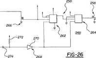
図26を特に参照すれば、1つの実施形態では、監視回路248は、第1のフリップフロップ262と第2のフリップフロップ264とを含んでいる。第1のフリップフロップ262は、電子コントローラ118及び第2のフリップフロップ264に接続されている。第2のフリップフロップ264は、第2のFET258に接続されている。
図示の実施形態では、第1のフリップフロップ262及び第2のフリップフロップ264は、JKフリップフロップである。第2のフリップフロップ264の反転出力(Q’)は、第2のFET258のゲートに接続されている。第2のフリップフロップ264のクロック入力(CLK)は、第1のフリップフロップ262の出力(Q)に接続されている。マイクロプロセッサ244によって、電力が第1のフリップフロップ262、第2のフリップフロップ264、第1のフリップフロップ262のJ入力及びK入力、及び第2のフリップフロップ264のJ入力に供給される。第2のFET258のドレインは、第1のFET256に接続され、第2のFET258のソースは、接地される。
第1のフリップフロップ262、第2のフリップフロップ264、第1のフリップフロップ262のJ入力及びK入力、及び第2のフリップフロップ264のJ入力への電力を遮断して、それを復帰させることによって、ウォッチドッグ回路248をリセットする。1つの実施形態では、電子コントローラ118は、モーター42の各回転の後、第1のフリップフロップ262及び第2のフリップフロップ264への電力を遮断し、第1のスイッチ246をオンにして次のサイクルを開始させる前、電力を供給する。これは、2つの効果を有し、即ち、電力を温存し、第1のフリップフロップ262及び第2のフリップフロップ264をリセットする。With particular reference to FIG. 26, in one embodiment, the
In the illustrated embodiment, the first flip-
Shut off and restore power to the first and second flip-
第1のフリップフロップ262のクロック入力(CLK)は、モーターセンサ254の出力に接続されている。第1のフリップフロップ262のクロック入力(CLK)はまた、第3のFET266を介してマイクロプロセッサ244に接続されている。第3のFET266は、マイクロプロセッサ244、モーターセンサ254及び監視回路248間を絶縁させる。この絶縁は、電子コントローラ118の短絡したピンにより、回転パルスがフリップフロップ262、264に達することを防止しないようにする。
第1のフリップフロップ262及び第2のフリップフロップ264の反転クリア入力(CLR’)は、バッファ回路268を介してマイクロプロセッサ244に接続されている。図示の実施形態では、バッファ回路268は、第1のバッファ270、第1の抵抗器272及びコンデンサ274を含んでいる。電子コントローラ118は、第1のスイッチ246をオンにして、第1のフリップフロップ262及び第2のフリップフロップ264への電力をオフにすることなしにそれらを反転クリア入力を介して連続的にリセットすることによって、電力をモーターに連続的に供給するのが良い。
1つの実施形態では、フリップフロップ262、264は、高い(「HIGH」)論理レベルから低い(「LOW」)論理レベルへの移行によってトリガーされる。バッファ回路268は、それへの入力がマイクロプロセッサ244によってHIGHに保持されているとき、誤差信号による移行を防止する。The clock input (CLK) of the first flip-
Inverted clear inputs (CLR ′) of the first flip-
In one embodiment, flip-
特に図27を参照すれば、モーター制御回路242は、第1のFET256及び光カプラセンサ276を含んでいる。フラッシュバックダイオード278が、第1のモータージャンクション280Aと第2のモータージャンクション280Bとに跨って接続されている。光カプラセンサ276のトランスミッテイングダイオードがスイッチを介して電力(V+)とアースに接続されている。この構成では、センサ276は、モーター42が稼動している間、動力が供給されるに過ぎず、電池寿命を温存する。光カプラセンサ276の出力は、第2のバッファ282を介して第3のトランジスタ266に接続されている。
第1のFET256のゲートは、マイクロプロセッサ244に接続されている。第1のFET256のドレインは、モーター42に接続され、そのソースは、第2のFET258のドレインに接続されている。With particular reference to FIG. 27, the
The gate of the
上述したように、電子コントローラ118は、モーター42を付勢させることによって薬剤を供給するようになっている。所望の流量は、モーター42を付勢させて、計算された期間についてモーター42の回転と回転との間待つことによって達成される。モーター42は、第1のFET256をオンにすることによって、付勢される。図示の実施形態では、第1のFET256は、マイクロプロセッサ244により第1のFET256のゲートの状態をLOWからHIGHに変化させることによってオンにされる。もし第2のFET258もオンであれば、電力がモーター42、第1のFET256及び第2のFET258を通って流れる。モーター42が完全に1回転したら、モーターセンサ254の出力は、HIGHからLOWに移行する。図示の実施形態では、この移行は、モーター回転信号である。モーター回転信号はまた、第3のFET266を介してマイクロプロセッサ244に伝達される。マイクロプロセッサ244は、モーター回転信号を受け取った後、第1のFET256のゲートの状態をHIGHからLOWに変化させることによって、第1のFET256をオフにする。
通常の作動中、次いで、マイクロプロセッサ244は、第1のフリップフロップ262及び第2のフリップフロップ264への電力をオフにする。上述したように、所望の流量及びモーター42の1回転当たりに配送される既知の薬剤量に基づいて、マイクロプロセッサ244は、モーターの回転と回転との間の待ち時間を計算する。待ち時間後、又は、待ち時間が終了する直前、マイクロプロセッサ244は、第1のフリップフロップ262及び第2のフリップフロップ264への電力を復帰させる。上述したように、これにより、第1のフリップフロップ262及び第2のフリップフロップ264をリセットする。次いで、マイクロプロセッサ244は、第1のFET256を再びオンにし、モーター42を付勢させる。As described above, the
During normal operation, the
マイクロプロセッサ244の故障又はその他の故障等の制御システム240の故障状態が存在し、ウォッチドッグ回路248がリセットされなければ、ウォッチドッグ回路248は、第2のFET258をオフにし、それにより、動力がモーター42に供給されることを防止する。
例えば、第1のFET256がオンである間にマイクロプロセッサ244が故障すれば、モーター42は、付勢され続ける。モーターセンサは、モーターの回転が完了するたびにモーター回転信号を発生させる。しかしながら、マイクロプロセッサは、ウォッチドッグ回路248をリセットしない、又は、それをリセットさせることができない。ウォッチドッグ回路248がリセットされずに、第1のフリップフロップ262のCLK入力に受け取られた2つの連続するモーター回転信号は、第2のフリップフロップ264の反転出力をHIGHからLOWにフリップし、かくして、第2のFET258をオフにする。
同様に、閉状態における第1のトランジスタ256の故障は、モーター42を連続的に付勢させる。マイクロプロセッサ244がウォッチドッグ回路248をリセットさせなければ、第1のフリップフロップ262のCLK入力に受け取られた連続するモーター回転信号は、第2のフリップフロップ264の反転出力をフリップし、かくして、第2のFET258をオフにする。
第2のFET258がオフ状態にあれば、電力はモーターに配送されない。If a fault condition of the
For example, if the
Similarly, failure of the
If the
図25に戻れば、制御システム240は、更に、最初の間だけ電子コントローラ118に接続されるキー284を含んでいる。1つの実施形態では、キー284は、 を組立てて電池45を取付けた後に制御システム240を試験するのにも使用される試験器具200の一部分である。最初の電源投入時、もしもキー284が存在するならば、制御システム240は初期化するだけである。キー284が存在しなければ、制御システム240は、非作動モードに入り、薬剤を配送することができない。
1つの実施形態では、最初のパワーアップ時、制御システム240は、キー284に信号を送る。キー284は、戻り信号が存在するならば、その存在を指示する戻り信号を制御システム240に配送する。キー284の使用により、電池又はその他の電源43を取外してそれを再挿入することによって、システム10が不正確にリセットされることができないことを確実にする。もしこれが起こり且つキー284が存在しないならば、システム10は作動しない。Returning to FIG. 25, the
In one embodiment,
制御システム240は、マイクロプロセッサ244に接続された水晶体285を含んでいる。水晶体285は、マイクロプロセッサ244が在来の仕方で作動する周波数を制御する。しかしながら、水晶体285が不正確に作動するならば、マイクロプロセッサ244は、予定された周波数よりも高い周波数又はそれよりも低い周波数の何れかで作動し始めても良い。マイクロプロセッサ244は、また、内部発振器286を含んでいる。1つの実施形態では、制御システム240は、水晶体285の周波数と内部発信機286と関連した周波数とを比較するようになっている。電子コントローラ118は、第1の周波数と第2の周波数との間の差を比較し、その差が所定の閾値よりも大きいならば、非作動状態に入るようになっている。かくして、水晶体285が故障に遭遇すれば、制御システム10は、作動することができなくなる。
本発明を例示として説明した。使用した用語は、限定ではなく、説明のためのものであることを理解すべきである。明らかに、本発明の多くの変更例及び変形例が、上述の教示に照らして可能である。従って、参照番号は単に便宜的なものであり、何ら限定をするものではないことを理解すべきであり、本発明は、特に説明した実施例以外にも実施可能である。
The invention has been described by way of example. It should be understood that the terminology used is for the purpose of description, not limitation. Obviously, many modifications and variations of the present invention are possible in light of the above teachings. Accordingly, it should be understood that the reference numbers are merely for convenience and are not limiting in any way, and the invention may be practiced other than as specifically described.
Claims (10)
Translated fromJapaneseベースハウジングと、
前記ベースハウジングの周りに配置された、患者に配送すべき薬剤を貯蔵するための薬剤リザーバと、
前記ベースハウジングによって支持され、薬剤を患者に配送するために交互に開状態と閉状態になるポンプ入口及びポンプ出口を有する、薬剤を患者に配送するためのポンプ組立体と、
前記薬剤リザーバ及び前記ポンプ組立体内への薬剤流体用のアクセスを構成するために、滅菌中、前記薬剤リザーバ及び前記ポンプ組立体と流体連通する、前記ベースハウジングから延びるポートと、
前記ベースハウジング内に配置され、滅菌中、前記ポンプ入口及び前記ポンプ出口の両方を開状態に保持して、滅菌流体を前記薬剤リザーバ、前記ポンプ入口及び前記ポンプ出口の中に浸透させ、前記システムを完全に滅菌するように前記ポンプ入口及び前記ポンプ出口に作動的に係合するアクチュエータと、
前記ポンプ入口に配置され且つ、通常、前記ポンプ入口を閉状態に維持するように付勢されている第1のピンチレバーと、
前記ポンプ出口に配置され且つ、通常、前記ポンプ出口を閉状態に維持するように付勢されている第2のピンチレバーと、を有することを特徴とする薬剤配送システム。An integrated drug delivery system for delivering drugs to a patient, suitable for complete sterilization with a sterile fluid,
A base housing;
A drug reservoir disposed about the base housing for storing a drug to be delivered to a patient;
A pump assembly for delivering medication to a patient supported by said base housing and having a pump inlet and a pump outlet that are alternately open and closed for delivering medication to the patient;
A port extending from the base housing in fluid communication with the drug reservoir and the pump assembly during sterilization to provide access for drug fluid into the drug reservoir and the pump assembly;
The system is disposed within the base housing and holds both the pump inlet and the pump outlet open during sterilization to allow sterilization fluid to penetrate into the drug reservoir, the pump inlet and the pump outlet, and An actuator operatively engaging the pump inlet and the pump outlet to completely sterilize the
A first pinch lever disposed at the pump inlet and normally biased to maintain the pump inlet closed;
And a second pinch lever disposed at the pump outlet and normally biased to maintain the pump outlet in a closed state.
前記ポンプ組立体から前記ポートに流入する滅菌流体用のアクセスを構成するために、前記ポンプ出口と前記ポートとの間に連結された薬剤流出チューブと、を有する、請求項1に記載の薬剤配送システム。A drug inlet tube connected between the port and the pump inlet to provide access for sterilizing fluid flowing from the port into the pump assembly;
The drug delivery according to claim 1, comprising a drug outlet tube connected between the pump outlet and the port to provide access for sterile fluid flowing from the pump assembly into the port. system.
Applications Claiming Priority (3)
| Application Number | Priority Date | Filing Date | Title |
|---|---|---|---|
| US27118701P | 2001-02-23 | 2001-02-23 | |
| PCT/US2002/005610WO2002068018A2 (en) | 2001-02-23 | 2002-02-23 | Integrated medication delivery system |
| US10/083,266US6679862B2 (en) | 2001-02-23 | 2002-02-23 | Integrated medication delivery system |
Publications (3)
| Publication Number | Publication Date |
|---|---|
| JP2004523305A JP2004523305A (en) | 2004-08-05 |
| JP2004523305A5 JP2004523305A5 (en) | 2005-12-22 |
| JP4058498B2true JP4058498B2 (en) | 2008-03-12 |
Family
ID=26769114
Family Applications (1)
| Application Number | Title | Priority Date | Filing Date |
|---|---|---|---|
| JP2002567381AExpired - Fee RelatedJP4058498B2 (en) | 2001-02-23 | 2002-02-23 | Integrated drug delivery system |
Country Status (6)
| Country | Link |
|---|---|
| US (5) | US6679862B2 (en) |
| EP (1) | EP1379291A4 (en) |
| JP (1) | JP4058498B2 (en) |
| AU (1) | AU2002244142A1 (en) |
| CA (1) | CA2431049C (en) |
| WO (1) | WO2002068018A2 (en) |
Families Citing this family (148)
| Publication number | Priority date | Publication date | Assignee | Title |
|---|---|---|---|---|
| US6796964B2 (en)* | 1997-11-19 | 2004-09-28 | Eidson Associates, Inc | Automatic veterinary medicament delivery system |
| US20040034331A1 (en) | 2001-02-23 | 2004-02-19 | Jason Toman | Integrated medication delivery system |
| US6893414B2 (en)* | 2002-08-12 | 2005-05-17 | Breg, Inc. | Integrated infusion and aspiration system and method |
| WO2004094823A2 (en) | 2003-04-23 | 2004-11-04 | Biovalve Technologies, Inc. | Hydraulically actuated pump for long duration medicament administration |
| US9033920B2 (en)* | 2003-10-02 | 2015-05-19 | Medtronic, Inc. | Determining catheter status |
| US7320676B2 (en)* | 2003-10-02 | 2008-01-22 | Medtronic, Inc. | Pressure sensing in implantable medical devices |
| US8323244B2 (en)* | 2007-03-30 | 2012-12-04 | Medtronic, Inc. | Catheter malfunction determinations using physiologic pressure |
| US9138537B2 (en) | 2003-10-02 | 2015-09-22 | Medtronic, Inc. | Determining catheter status |
| KR100519247B1 (en)* | 2003-10-07 | 2005-10-06 | 에이스메디칼 주식회사 | Flat round liguid medicine provider |
| US9089636B2 (en) | 2004-07-02 | 2015-07-28 | Valeritas, Inc. | Methods and devices for delivering GLP-1 and uses thereof |
| US20060084924A1 (en)* | 2004-10-20 | 2006-04-20 | Susi Koch | Insulin pump pouch assembly |
| US7648483B2 (en)* | 2004-11-22 | 2010-01-19 | Intelliject, Inc. | Devices, systems and methods for medicament delivery |
| US8361026B2 (en)* | 2005-02-01 | 2013-01-29 | Intelliject, Inc. | Apparatus and methods for self-administration of vaccines and other medicaments |
| AU2006210865B2 (en)* | 2005-02-01 | 2008-12-04 | Kaleo, Inc. | Devices, systems, and methods for medicament delivery |
| US7731686B2 (en)* | 2005-02-01 | 2010-06-08 | Intelliject, Inc. | Devices, systems and methods for medicament delivery |
| US8231573B2 (en) | 2005-02-01 | 2012-07-31 | Intelliject, Inc. | Medicament delivery device having an electronic circuit system |
| US9022980B2 (en) | 2005-02-01 | 2015-05-05 | Kaleo, Inc. | Medical injector simulation device |
| US8206360B2 (en) | 2005-02-01 | 2012-06-26 | Intelliject, Inc. | Devices, systems and methods for medicament delivery |
| GB2437228B (en)* | 2005-02-11 | 2009-12-30 | Stryker Corp | Reprogrammable fluid delivery system and method of use |
| EP1866009A1 (en)* | 2005-02-25 | 2007-12-19 | Novo Nordisk A/S | Pump assembly with safety valve |
| WO2006130491A2 (en)* | 2005-05-27 | 2006-12-07 | Stryker Corporation | Hand-held fluid delivery device with sensors to determine fluid pressure and volume of fluid delivered to intervertebral discs during discography |
| EP3165247B1 (en)* | 2006-02-09 | 2020-10-28 | DEKA Products Limited Partnership | Pumping fluid delivery systems and methods using force application assembley |
| WO2007126851A2 (en)* | 2006-03-29 | 2007-11-08 | Intelliject, Llc | Devices, systems and methods for medicament delivery |
| CN101438327B (en)* | 2006-03-29 | 2013-11-06 | 因特利杰克特有限公司 | Devices, systems and methods for medicament delivery |
| WO2007115039A2 (en) | 2006-03-30 | 2007-10-11 | Valeritas, Llc | Multi-cartridge fluid delivery device |
| EP2030643A1 (en)* | 2006-04-06 | 2009-03-04 | Medtronic, Inc. | Systems and methods for identifying catheter malfunctions using pressure sensing |
| EP2037999B1 (en) | 2006-07-07 | 2016-12-28 | Proteus Digital Health, Inc. | Smart parenteral administration system |
| KR100767760B1 (en) | 2006-07-27 | 2007-10-17 | 신동아 | Automatic disk stimulation inspection system and its provision method |
| EP2125075A2 (en)* | 2007-01-22 | 2009-12-02 | Intelliject, Inc. | Medical injector with compliance tracking and monitoring |
| US8390244B2 (en)* | 2007-03-30 | 2013-03-05 | Nipro Healthcare Systems, Llc | Rechargeable battery backup apparatus and method for insulin pump |
| US9044537B2 (en) | 2007-03-30 | 2015-06-02 | Medtronic, Inc. | Devices and methods for detecting catheter complications |
| US9333293B2 (en)* | 2007-05-09 | 2016-05-10 | Acist Medical Systems, Inc. | Injector device, method, and computer program product for detecting a vacuum within a syringe |
| US7771391B2 (en)* | 2007-09-28 | 2010-08-10 | Calibra Medical, Inc. | Disposable infusion device with snap action actuation |
| BRPI0817907B8 (en) | 2007-10-02 | 2021-06-22 | Lamodel Ltd | apparatus for administering a substance to an individual |
| US10420880B2 (en) | 2007-10-02 | 2019-09-24 | West Pharma. Services IL, Ltd. | Key for securing components of a drug delivery system during assembly and/or transport and methods of using same |
| US9656019B2 (en) | 2007-10-02 | 2017-05-23 | Medimop Medical Projects Ltd. | Apparatuses for securing components of a drug delivery system during transport and methods of using same |
| US9345836B2 (en) | 2007-10-02 | 2016-05-24 | Medimop Medical Projects Ltd. | Disengagement resistant telescoping assembly and unidirectional method of assembly for such |
| US7967795B1 (en) | 2010-01-19 | 2011-06-28 | Lamodel Ltd. | Cartridge interface assembly with driving plunger |
| US9125979B2 (en) | 2007-10-25 | 2015-09-08 | Proteus Digital Health, Inc. | Fluid transfer port information system |
| US8419638B2 (en) | 2007-11-19 | 2013-04-16 | Proteus Digital Health, Inc. | Body-associated fluid transport structure evaluation devices |
| USD994111S1 (en) | 2008-05-12 | 2023-08-01 | Kaleo, Inc. | Medicament delivery device cover |
| US8021344B2 (en) | 2008-07-28 | 2011-09-20 | Intelliject, Inc. | Medicament delivery device configured to produce an audible output |
| WO2010006047A2 (en)* | 2008-07-10 | 2010-01-14 | Ethicon Endo-Surgery, Inc. | Medical system which controls delivery of a drug and which includes a backpack pouch |
| US12097357B2 (en) | 2008-09-15 | 2024-09-24 | West Pharma. Services IL, Ltd. | Stabilized pen injector |
| US9393369B2 (en) | 2008-09-15 | 2016-07-19 | Medimop Medical Projects Ltd. | Stabilized pen injector |
| EP2370125B1 (en)* | 2008-10-07 | 2019-04-10 | Roche Diabetes Care GmbH | Skin securable drug delivery device with a shock absorbing protective shield |
| EP2334354A4 (en)* | 2008-10-15 | 2014-01-22 | Symbios Medical Products Llc | Electronic flow control |
| DK2196231T3 (en)* | 2008-12-12 | 2013-06-03 | Hoffmann La Roche | Outpatient drug infusion system with a flexible container filler |
| US20100211002A1 (en)* | 2009-02-18 | 2010-08-19 | Davis David L | Electromagnetic infusion pump with integral flow monitor |
| US8353864B2 (en)* | 2009-02-18 | 2013-01-15 | Davis David L | Low cost disposable infusion pump |
| US8197235B2 (en)* | 2009-02-18 | 2012-06-12 | Davis David L | Infusion pump with integrated permanent magnet |
| US7806865B1 (en)* | 2009-05-20 | 2010-10-05 | Alcon Research, Ltd. | Pressurized irrigation squeeze band |
| US9480789B2 (en)* | 2009-06-01 | 2016-11-01 | Ethicon Endo-Surgery, Inc. | Method and sedation delivery system including a pump assembly and a co-formulation of first and second drugs |
| US9242042B2 (en)* | 2009-07-21 | 2016-01-26 | Ethicon Endo-Surgery, Inc. | Drug delivery system including a drug-container holder and a pump assembly |
| US8241018B2 (en) | 2009-09-10 | 2012-08-14 | Tyco Healthcare Group Lp | Compact peristaltic medical pump |
| US8157769B2 (en) | 2009-09-15 | 2012-04-17 | Medimop Medical Projects Ltd. | Cartridge insertion assembly for drug delivery system |
| US10071196B2 (en) | 2012-05-15 | 2018-09-11 | West Pharma. Services IL, Ltd. | Method for selectively powering a battery-operated drug-delivery device and device therefor |
| US10071198B2 (en) | 2012-11-02 | 2018-09-11 | West Pharma. Servicees IL, Ltd. | Adhesive structure for medical device |
| USD626647S1 (en)* | 2009-10-13 | 2010-11-02 | Smiths Medical Asd, Inc. | Infusion pump cassette |
| US7967773B2 (en)* | 2009-10-13 | 2011-06-28 | Smiths Medical Asd, Inc. | Two piece medication cassette closure apparatus and method |
| DK2327435T3 (en) | 2009-11-11 | 2012-04-23 | Hoffmann La Roche | Apparatus and method for determining the filling level of a flexible medicine reservoir |
| US8348898B2 (en) | 2010-01-19 | 2013-01-08 | Medimop Medical Projects Ltd. | Automatic needle for drug pump |
| US11164672B2 (en) | 2010-01-22 | 2021-11-02 | Deka Products Limited Partnership | System and apparatus for electronic patient care |
| US11210611B2 (en) | 2011-12-21 | 2021-12-28 | Deka Products Limited Partnership | System, method, and apparatus for electronic patient care |
| US11244745B2 (en) | 2010-01-22 | 2022-02-08 | Deka Products Limited Partnership | Computer-implemented method, system, and apparatus for electronic patient care |
| US20110313789A1 (en) | 2010-01-22 | 2011-12-22 | Deka Products Limited Partnership | Electronic patient monitoring system |
| US9677555B2 (en) | 2011-12-21 | 2017-06-13 | Deka Products Limited Partnership | System, method, and apparatus for infusing fluid |
| US11881307B2 (en) | 2012-05-24 | 2024-01-23 | Deka Products Limited Partnership | System, method, and apparatus for electronic patient care |
| US10453157B2 (en) | 2010-01-22 | 2019-10-22 | Deka Products Limited Partnership | System, method, and apparatus for electronic patient care |
| US10911515B2 (en) | 2012-05-24 | 2021-02-02 | Deka Products Limited Partnership | System, method, and apparatus for electronic patient care |
| WO2013095459A1 (en)* | 2011-12-21 | 2013-06-27 | Deka Products Limited Partnership | System, method, and apparatus for electronic patient care |
| US10242159B2 (en) | 2010-01-22 | 2019-03-26 | Deka Products Limited Partnership | System and apparatus for electronic patient care |
| BR112012019212A2 (en) | 2010-02-01 | 2017-06-13 | Proteus Digital Health Inc | data collection system |
| EP2531096A4 (en) | 2010-02-01 | 2013-09-11 | Proteus Digital Health Inc | Two-wrist data gathering system |
| EP2569031B1 (en) | 2010-05-10 | 2017-10-11 | Medimop Medical Projects Ltd. | Low volume accurate injector |
| US9173999B2 (en) | 2011-01-26 | 2015-11-03 | Kaleo, Inc. | Devices and methods for delivering medicaments from a multi-chamber container |
| US8939943B2 (en) | 2011-01-26 | 2015-01-27 | Kaleo, Inc. | Medicament delivery device for administration of opioid antagonists including formulations for naloxone |
| US8627816B2 (en) | 2011-02-28 | 2014-01-14 | Intelliject, Inc. | Medicament delivery device for administration of opioid antagonists including formulations for naloxone |
| USD702834S1 (en) | 2011-03-22 | 2014-04-15 | Medimop Medical Projects Ltd. | Cartridge for use in injection device |
| DK3685877T3 (en) | 2011-06-03 | 2023-10-02 | Fisher & Paykel Healthcare Ltd | MEDICAL TUBES CONSISTING OF CONDUCTIVE FILAMENTS AND METHODS OF PRODUCTION |
| US12196364B2 (en) | 2011-12-21 | 2025-01-14 | DEKA Research Products Limited Partnership | System, method, and apparatus for clamping |
| US11295846B2 (en) | 2011-12-21 | 2022-04-05 | Deka Products Limited Partnership | System, method, and apparatus for infusing fluid |
| US10563681B2 (en) | 2011-12-21 | 2020-02-18 | Deka Products Limited Partnership | System, method, and apparatus for clamping |
| US9675756B2 (en) | 2011-12-21 | 2017-06-13 | Deka Products Limited Partnership | Apparatus for infusing fluid |
| EP2809375B1 (en) | 2012-01-31 | 2021-08-11 | Medimop Medical Projects Ltd. | Time dependent drug delivery apparatus |
| US9072827B2 (en) | 2012-03-26 | 2015-07-07 | Medimop Medical Projects Ltd. | Fail safe point protector for needle safety flap |
| US9463280B2 (en) | 2012-03-26 | 2016-10-11 | Medimop Medical Projects Ltd. | Motion activated septum puncturing drug delivery device |
| US10668213B2 (en) | 2012-03-26 | 2020-06-02 | West Pharma. Services IL, Ltd. | Motion activated mechanisms for a drug delivery device |
| US8974415B2 (en) | 2012-04-10 | 2015-03-10 | Smiths Medical Asd, Inc. | Flow stop insert apparatus and methods |
| US20130310738A1 (en)* | 2012-05-21 | 2013-11-21 | Lifemedix, Llc | Portable intravenous fluid delivery device with a user interface |
| US9522235B2 (en) | 2012-05-22 | 2016-12-20 | Kaleo, Inc. | Devices and methods for delivering medicaments from a multi-chamber container |
| CN116370749A (en)* | 2012-05-24 | 2023-07-04 | 德卡产品有限公司 | Devices for infusion of fluids |
| WO2014061977A1 (en)* | 2012-10-15 | 2014-04-24 | 에이스메디칼 주식회사 | Chemical solution supplying apparatus capable of being easily assembled and of totally discharging injected chemicals |
| GB2575363B (en)* | 2012-11-14 | 2020-04-22 | Fisher & Paykel Healthcare Ltd | Zone heating for respiratory circuits |
| GB2527210B (en) | 2012-12-04 | 2020-02-05 | Fisher & Paykel Healthcare Ltd | A Breathing Tube and Method of Manufacturing a Breathing Tube |
| ITPD20120367A1 (en)* | 2012-12-06 | 2014-06-07 | Italfiduciaria Srl | PERISTALTIC PUMP FOR ADMINISTRATION OF DRUGS OR FLUIDS |
| GB2526948A (en) | 2012-12-27 | 2015-12-09 | Kaleo Inc | Systems for locating and interacting with medicament delivery devices |
| US9421323B2 (en) | 2013-01-03 | 2016-08-23 | Medimop Medical Projects Ltd. | Door and doorstop for portable one use drug delivery apparatus |
| US9011164B2 (en) | 2013-04-30 | 2015-04-21 | Medimop Medical Projects Ltd. | Clip contact for easy installation of printed circuit board PCB |
| US9889256B2 (en) | 2013-05-03 | 2018-02-13 | Medimop Medical Projects Ltd. | Sensing a status of an infuser based on sensing motor control and power input |
| US10814091B2 (en) | 2013-10-24 | 2020-10-27 | Fisher & Paykel Healthcare Limited | System for delivery of respiratory gases |
| CN106029147B (en) | 2013-12-20 | 2020-01-21 | 费雪派克医疗保健有限公司 | Humidification system connection |
| CN111265754B (en) | 2014-03-17 | 2023-06-06 | 费雪派克医疗保健有限公司 | Medical tube for respiratory system |
| US9662437B2 (en) | 2014-04-28 | 2017-05-30 | Smiths Medical Asd, Inc. | Infusion pump pressure plate |
| US9517307B2 (en) | 2014-07-18 | 2016-12-13 | Kaleo, Inc. | Devices and methods for delivering opioid antagonists including formulations for naloxone |
| EP3193975B1 (en) | 2014-09-18 | 2022-07-06 | DEKA Products Limited Partnership | Apparatus and method for infusing fluid through a tube by appropriately heating the tube |
| US9795534B2 (en) | 2015-03-04 | 2017-10-24 | Medimop Medical Projects Ltd. | Compliant coupling assembly for cartridge coupling of a drug delivery device |
| US10251813B2 (en) | 2015-03-04 | 2019-04-09 | West Pharma. Services IL, Ltd. | Flexibly mounted cartridge alignment collar for drug delivery device |
| US10695495B2 (en) | 2015-03-24 | 2020-06-30 | Kaleo, Inc. | Devices and methods for delivering a lyophilized medicament |
| US10293120B2 (en) | 2015-04-10 | 2019-05-21 | West Pharma. Services IL, Ltd. | Redundant injection device status indication |
| US9744297B2 (en) | 2015-04-10 | 2017-08-29 | Medimop Medical Projects Ltd. | Needle cannula position as an input to operational control of an injection device |
| US10149943B2 (en) | 2015-05-29 | 2018-12-11 | West Pharma. Services IL, Ltd. | Linear rotation stabilizer for a telescoping syringe stopper driverdriving assembly |
| CN113181477B (en) | 2015-06-04 | 2023-07-14 | 麦迪麦珀医疗工程有限公司 | Cartridge insertion for drug delivery device |
| CA2990950A1 (en) | 2015-06-30 | 2017-01-05 | Kaleo, Inc. | Auto-injectors for administration of a medicament within a prefilled syringe |
| US10532135B2 (en) | 2015-06-30 | 2020-01-14 | Carefusion 2200, Inc. | Drainage system with O-ring |
| WO2017040211A1 (en)* | 2015-08-28 | 2017-03-09 | Crisi Medical Systems, Inc. | Flow sensor system with connection assembly |
| WO2017043981A1 (en) | 2015-09-09 | 2017-03-16 | Po-Yen Liu | Zone heating for respiratory circuits |
| US10576207B2 (en) | 2015-10-09 | 2020-03-03 | West Pharma. Services IL, Ltd. | Angled syringe patch injector |
| US9987432B2 (en) | 2015-09-22 | 2018-06-05 | West Pharma. Services IL, Ltd. | Rotation resistant friction adapter for plunger driver of drug delivery device |
| US11318254B2 (en) | 2015-10-09 | 2022-05-03 | West Pharma. Services IL, Ltd. | Injector needle cap remover |
| JP6885960B2 (en) | 2016-01-21 | 2021-06-16 | ウェスト ファーマ サービシーズ イスラエル リミテッド | Drug delivery device with visual indicators |
| US10646643B2 (en) | 2016-01-21 | 2020-05-12 | West Pharma. Services IL, Ltd. | Needle insertion and retraction mechanism |
| EP3711793B1 (en) | 2016-01-21 | 2021-12-01 | West Pharma Services IL, Ltd. | A method of connecting a cartridge to an automatic injector |
| US11389597B2 (en) | 2016-03-16 | 2022-07-19 | West Pharma. Services IL, Ltd. | Staged telescopic screw assembly having different visual indicators |
| WO2017189089A1 (en)* | 2016-04-29 | 2017-11-02 | Amgen Inc. | Drug delivery device with messaging label |
| CN109310831B (en) | 2016-06-02 | 2021-11-23 | 西医药服务以色列有限公司 | Three position needle retraction |
| JP7059251B2 (en) | 2016-08-01 | 2022-04-25 | ウェスト ファーマ サービシーズ イスラエル リミテッド | A spring that prevents the door from closing halfway |
| US11338090B2 (en) | 2016-08-01 | 2022-05-24 | West Pharma. Services IL, Ltd. | Anti-rotation cartridge pin |
| USD813380S1 (en) | 2016-08-05 | 2018-03-20 | Amgen Inc. | On-body injector |
| EP3544662B1 (en) | 2016-12-22 | 2024-11-27 | Fisher & Paykel Healthcare Limited | Medical tubes and methods of manufacture |
| CA3046354A1 (en) | 2017-01-17 | 2018-07-26 | Kaleo, Inc. | Medicament delivery devices with wireless connectivity and event detection |
| EP3630226A1 (en) | 2017-05-30 | 2020-04-08 | West Pharma. Services Il, Ltd. | Modular drive train for wearable injector |
| CN109107400A (en)* | 2017-06-22 | 2019-01-01 | 周厚荣 | A kind of device preventing drug crystallization |
| JP7402799B2 (en) | 2017-12-22 | 2023-12-21 | ウェスト ファーマ サービシーズ イスラエル リミテッド | Syringes available with different cartridge sizes |
| EP3749387A4 (en) | 2018-02-11 | 2021-11-10 | Eitan Medical Ltd. | INFUSION PUMP WITH FLEXIBLE STROKE |
| WO2019213218A1 (en)* | 2018-05-01 | 2019-11-07 | Csp Technologies, Inc. | Medicament delivery device and method of using and making same |
| US11929160B2 (en) | 2018-07-16 | 2024-03-12 | Kaleo, Inc. | Medicament delivery devices with wireless connectivity and compliance detection |
| JP7047185B2 (en) | 2018-08-16 | 2022-04-04 | デカ・プロダクツ・リミテッド・パートナーシップ | Medical pump |
| IL273061B2 (en) | 2019-03-04 | 2024-01-01 | Avoset Health Ltd | In cycle pressure measurement |
| ES3033347T3 (en) | 2019-03-05 | 2025-08-01 | Eitan Medical Ltd | Anti-free-flow valve |
| EP3934714A1 (en) | 2019-03-05 | 2022-01-12 | Eitan Medical Ltd. | Infusion pump with valve compensation |
| ES2989157T3 (en) | 2019-03-05 | 2024-11-25 | Eitan Medical Ltd | Infusion pump cassette closure |
| US12318576B2 (en) | 2019-03-05 | 2025-06-03 | Eitan Medical Ltd. | Infusion pump with toggling capability |
| CA3145580A1 (en) | 2019-08-09 | 2021-02-18 | Kaleo, Inc. | Devices and methods for delivery of substances within a prefilled syringe |
| US12303649B2 (en)* | 2020-01-03 | 2025-05-20 | Stanley Batiste | Catheter clearance device and method of use |
| WO2022147985A1 (en)* | 2021-01-05 | 2022-07-14 | Medtrum Technologies Inc. | A skin patch drug infusion device |
| US12268847B1 (en) | 2021-02-10 | 2025-04-08 | Kaleo, Inc. | Devices and methods for delivery of substances within a medicament container |
| EP4568636A2 (en)* | 2022-08-12 | 2025-06-18 | Luminoah, Inc. | Wearable fluid delivery system |
Family Cites Families (91)
| Publication number | Priority date | Publication date | Assignee | Title |
|---|---|---|---|---|
| US2734526A (en) | 1956-02-14 | aagaard | ||
| US681076A (en)* | 1901-01-17 | 1901-08-20 | David W Porter | Hydraulic valve for presses. |
| US783971A (en) | 1904-03-28 | 1905-02-28 | Meinecke & Co | Sputum-cup and holder or container therefor. |
| US2423701A (en) | 1945-01-01 | 1947-07-08 | Marquette Metal Products Co | Pump |
| US2849997A (en) | 1954-09-10 | 1958-09-02 | Licencia Talalmany Okat Erteke | Fuel injection pumps for internal combustion engines |
| US3130586A (en) | 1960-07-13 | 1964-04-28 | Honeywell Regulator Co | Pressure measuring apparatus |
| US3149492A (en) | 1961-03-06 | 1964-09-22 | Astra Inc | Fluid pressure gauge |
| US3418853A (en) | 1966-01-10 | 1968-12-31 | Statham Instrument Inc | Blood pressure transducer |
| US3603152A (en) | 1970-02-05 | 1971-09-07 | Columbia Research Lab Inc | Transducer for detecting pressure changes in fluid flow |
| US3731679A (en) | 1970-10-19 | 1973-05-08 | Sherwood Medical Ind Inc | Infusion system |
| US4027536A (en) | 1975-10-20 | 1977-06-07 | Canadian Patents And Development Limited | Transducer for engine fuel injection monitoring |
| US4139008A (en) | 1975-11-21 | 1979-02-13 | Wolfgang Wagner | Controlled-dose injection apparatus |
| DE2649358C3 (en) | 1976-05-07 | 1980-09-18 | List, Hans, Prof. Dipl.-Ing. Dr.Dr. H.C., Graz (Oesterreich) | Device for recording the internal pressure or the pressure profile in a pipeline |
| US4210173A (en) | 1976-12-06 | 1980-07-01 | American Hospital Supply Corporation | Syringe pumping system with valves |
| US4141252A (en) | 1977-11-04 | 1979-02-27 | Lodge Arthur S | Flush pressure transducers for measuring pressures in a flowing fluid |
| CA1081501A (en) | 1977-11-10 | 1980-07-15 | Ronald Price | Diesel fuel pipe transducer |
| US4210138A (en) | 1977-12-02 | 1980-07-01 | Baxter Travenol Laboratories, Inc. | Metering apparatus for a fluid infusion system with flow control station |
| US4177810A (en) | 1977-12-23 | 1979-12-11 | Damon Corporation | Pneumatic injection apparatus |
| US4484479A (en) | 1978-04-05 | 1984-11-27 | Richard Eckhardt | Gas flow metering |
| US4174637A (en) | 1978-10-19 | 1979-11-20 | International Business Machines Corporation | Pressure monitoring system |
| US4202333A (en) | 1978-11-08 | 1980-05-13 | Minnesota Mining And Manufacturing Company | Fluid dispensing device |
| US4391600A (en)* | 1979-03-09 | 1983-07-05 | Avi, Inc. | Nonpulsating IV pump and disposable pump chamber |
| US4410322A (en) | 1979-03-09 | 1983-10-18 | Avi, Inc. | Nonpulsating TV pump and disposable pump chamber |
| US4236880A (en) | 1979-03-09 | 1980-12-02 | Archibald Development Labs, Inc. | Nonpulsating IV pump and disposable pump chamber |
| US4265240A (en) | 1979-04-16 | 1981-05-05 | Imed Corporation | Apparatus for providing a controlled introduction of intravenous fluid to a patient |
| US4318400A (en) | 1980-01-18 | 1982-03-09 | Alza Corporation | Medical infusor |
| US4446344A (en) | 1980-02-21 | 1984-05-01 | International Freezer Corp. | Pressure operated switch including an expandable flat tube |
| AT374280B (en) | 1980-06-16 | 1984-04-10 | List Hans | MEASURING VALUES FOR MEASURING MECHANICAL SIZES ON HOLLOW BODIES |
| DE3035670A1 (en) | 1980-09-22 | 1982-04-29 | Siemens AG, 1000 Berlin und 8000 München | DEVICE FOR INFUSING LIQUIDS IN HUMAN OR ANIMAL BODIES |
| US4460358A (en) | 1980-11-07 | 1984-07-17 | Ivac Corporation | Combined load and latch mechanism for fluid flow control apparatus |
| US4381006A (en) | 1980-11-10 | 1983-04-26 | Abbott Laboratories | Continuous low flow rate fluid dispenser |
| US4398908A (en) | 1980-11-28 | 1983-08-16 | Siposs George G | Insulin delivery system |
| US4396385A (en) | 1980-12-05 | 1983-08-02 | Baxter Travenol Laboratories, Inc. | Flow metering apparatus for a fluid infusion system |
| US4398542A (en) | 1980-12-15 | 1983-08-16 | Ivac Corporation | Pressure diaphragm |
| US4416595A (en) | 1981-03-13 | 1983-11-22 | Baxter Travenol Laboratories, Inc. | Miniature rotary infusion pump with slide latch and detachable power source |
| US4384578A (en) | 1981-04-16 | 1983-05-24 | The United States Of America As Represented By The Administrator Of The National Aeronautics And Space Administration | Bio-medical flow sensor |
| US4411651A (en) | 1981-05-26 | 1983-10-25 | Pacesetter Systems, Inc. | Device and method useful in monitoring fluid flow in a drug injector |
| GB2101230B (en) | 1981-06-13 | 1984-10-10 | Lucas Ind Plc | Fuel injection pump |
| JPS587253A (en) | 1981-07-04 | 1983-01-17 | テルモ株式会社 | Drug liquid pouring apparatus |
| US4456223A (en) | 1981-12-03 | 1984-06-26 | Bentley Laboratories, Inc. | Flow control apparatus |
| US4487603A (en)* | 1982-11-26 | 1984-12-11 | Cordis Corporation | Implantable microinfusion pump system |
| US4493704A (en) | 1982-11-29 | 1985-01-15 | Oximetrix, Inc. | Portable fluid infusion apparatus |
| US4483196A (en) | 1983-03-07 | 1984-11-20 | Kulite Semiconductor Products, Inc. | Tubular transducer structures |
| US4550748A (en) | 1983-04-08 | 1985-11-05 | Warner-Lambert Company | Fluid flow regulating unit for intravascular catheter systems |
| US4548607A (en)* | 1983-04-13 | 1985-10-22 | Cordis Corporation | Implantable manually actuated medication dispensing system |
| US4657486A (en) | 1984-01-13 | 1987-04-14 | Stempfle Julius E | Portable infusion device |
| US5100380A (en)* | 1984-02-08 | 1992-03-31 | Abbott Laboratories | Remotely programmable infusion system |
| US4559038A (en) | 1984-10-19 | 1985-12-17 | Deltec Systems, Inc. | Drug delivery system |
| US4565542A (en) | 1984-10-19 | 1986-01-21 | Deltec Systems, Inc. | Locking mechanism for a drug delivery system |
| US4650469A (en)* | 1984-10-19 | 1987-03-17 | Deltec Systems, Inc. | Drug delivery system |
| US4559040A (en) | 1984-10-30 | 1985-12-17 | Pancretec, Inc. | Segmented peristaltic pump chamber |
| US4741733A (en) | 1985-01-07 | 1988-05-03 | Baxter Travenol Laboratories, Inc. | Infusor having a distal flow regulator |
| US4681513A (en) | 1985-02-01 | 1987-07-21 | Jeol Ltd. | Two-stage pump assembly |
| US4636197A (en) | 1985-02-15 | 1987-01-13 | Ping Chu | Intravenous fluid infusion device |
| US4813937A (en) | 1986-05-07 | 1989-03-21 | Vaillancourt Vincent L | Ambulatory disposable infusion delivery system |
| US4938223A (en) | 1988-03-28 | 1990-07-03 | T. H. Charters, Inc. | Transcutaneous nerve block device |
| US5053031A (en)* | 1988-03-29 | 1991-10-01 | Baxter International Inc. | Pump infusion system |
| US5017059A (en) | 1988-05-17 | 1991-05-21 | Patient Solutions, Inc. | Infusion device with disposable elements |
| US5085631A (en) | 1988-08-02 | 1992-02-04 | Thomas Jefferson University | Method and kit for administering spinal subarachnoid anesthesia |
| US5059182A (en) | 1989-04-12 | 1991-10-22 | David H. Laing | Portable infusion device |
| US4973312A (en) | 1989-05-26 | 1990-11-27 | Andrew Daniel E | Method and system for inserting spinal catheters |
| US5165873A (en) | 1989-10-10 | 1992-11-24 | Imed Corporation | Two-cycle peristaltic pump |
| US5135500A (en) | 1989-10-31 | 1992-08-04 | Prime Medical Products, Inc. | Self-driven pump device |
| US5165874A (en) | 1990-05-04 | 1992-11-24 | Block Medical, Inc. | Disposable infusion apparatus and peristaltic pump for use therewith |
| US5078683A (en) | 1990-05-04 | 1992-01-07 | Block Medical, Inc. | Programmable infusion system |
| IL94522A (en) | 1990-05-28 | 1994-02-27 | Joseph Eldor | Device for combined spinal and epidural anesthesia |
| US5078679A (en) | 1990-11-13 | 1992-01-07 | Reese H William | Post-surgical anesthesia at a continuous and progressively decreasing administration rate |
| US5127907A (en) | 1990-12-06 | 1992-07-07 | Abbott Laboratories | System for eliminating or reducing static electricity in infusion pumping systems |
| US5181910A (en) | 1991-02-28 | 1993-01-26 | Pharmacia Deltec, Inc. | Method and apparatus for a fluid infusion system with linearized flow rate change |
| US5207645A (en) | 1991-06-25 | 1993-05-04 | Medication Delivery Devices | Infusion pump, treatment fluid bag therefor, and method for the use thereof |
| US6090071A (en)* | 1992-04-17 | 2000-07-18 | Science Incorporated | Fluid dispenser with fill adapter |
| JP3373558B2 (en) | 1992-04-23 | 2003-02-04 | 松下電工株式会社 | Small pump device |
| US5342313A (en) | 1992-11-02 | 1994-08-30 | Infusion Technologies Corporation | Fluid pump for a flexible, variable geometry reservoir |
| US5364242A (en) | 1992-11-25 | 1994-11-15 | Pharmacia Deltec, Inc. | Pump apparatus and method including double activation pump apparatus |
| US5261882A (en) | 1993-04-26 | 1993-11-16 | Sealfon Andrew I | Negator spring-powered syringe |
| US5540561A (en) | 1993-10-28 | 1996-07-30 | Sims Deltec, Inc. | Reservoir enclosure arrangements |
| US6007310A (en) | 1993-11-23 | 1999-12-28 | Sarcos, Lc | Volumetric pump with sterility seal |
| US5807075A (en) | 1993-11-23 | 1998-09-15 | Sarcos, Inc. | Disposable ambulatory microprocessor controlled volumetric pump |
| US5632606A (en) | 1993-11-23 | 1997-05-27 | Sarcos Group | Volumetric pump/valve |
| US5931647A (en) | 1993-11-23 | 1999-08-03 | Sarcos, Inc. | Volumetric pump with bi-directional piston seal |
| EP0737079B1 (en) | 1993-12-30 | 1998-07-22 | Graseby Medical Limited | Medical infusion pumps |
| US5695473A (en) | 1994-07-27 | 1997-12-09 | Sims Deltec, Inc. | Occlusion detection system for an infusion pump |
| US5575770A (en) | 1995-04-05 | 1996-11-19 | Therex Corporation | Implantable drug infusion system with safe bolus capability |
| PT821566E (en) | 1995-04-20 | 2004-03-31 | Acist Medical Sys Inc | ANGIOGRAPHIC INJECTOR |
| US5772635A (en) | 1995-05-15 | 1998-06-30 | Alaris Medical Systems, Inc. | Automated infusion system with dose rate calculator |
| US5788673A (en) | 1995-06-05 | 1998-08-04 | Atrion Medical Products, Inc. | Drug infusion system |
| US5603364A (en) | 1995-07-07 | 1997-02-18 | Opw Fueling Components Europe B.V. | Spout for a fuel dispensing nozzle |
| GB9601147D0 (en) | 1996-01-19 | 1996-03-20 | Smiths Industries Ltd | Spinal epidural needle assemblies |
| US5853373A (en) | 1996-08-05 | 1998-12-29 | Becton, Dickinson And Company | Bi-level charge pulse apparatus to facilitate nerve location during peripheral nerve block procedures |
| US6666665B1 (en) | 1999-03-04 | 2003-12-23 | Baxter International Inc. | Fluid delivery mechanism having a plurality of plungers for compressing a metering chamber |
| US6558352B1 (en)* | 2000-05-30 | 2003-05-06 | Verilogik, Inc. | System and method for variable dosage medicine delivery |
- 2002
- 2002-02-23JPJP2002567381Apatent/JP4058498B2/ennot_activeExpired - Fee Related
- 2002-02-23USUS10/083,266patent/US6679862B2/ennot_activeExpired - Lifetime
- 2002-02-23AUAU2002244142Apatent/AU2002244142A1/ennot_activeAbandoned
- 2002-02-23EPEP02709671Apatent/EP1379291A4/ennot_activeWithdrawn
- 2002-02-23WOPCT/US2002/005610patent/WO2002068018A2/enactiveApplication Filing
- 2002-02-23CACA2431049Apatent/CA2431049C/ennot_activeExpired - Lifetime
- 2002-09-04USUS10/234,400patent/US7048715B2/ennot_activeExpired - Lifetime
- 2002-09-04USUS10/234,831patent/US6908452B2/ennot_activeExpired - Lifetime
- 2003
- 2003-11-04USUS10/701,207patent/US7497842B2/ennot_activeExpired - Lifetime
- 2008
- 2008-07-14USUS12/172,892patent/US8328786B2/ennot_activeExpired - Fee Related
Also Published As
| Publication number | Publication date |
|---|---|
| AU2002244142A1 (en) | 2002-09-12 |
| US8328786B2 (en) | 2012-12-11 |
| US7497842B2 (en) | 2009-03-03 |
| US7048715B2 (en) | 2006-05-23 |
| US20040106902A1 (en) | 2004-06-03 |
| WO2002068018A3 (en) | 2003-04-03 |
| EP1379291A4 (en) | 2008-09-24 |
| EP1379291A2 (en) | 2004-01-14 |
| US20020198493A1 (en) | 2002-12-26 |
| CA2431049A1 (en) | 2002-09-06 |
| US20080275425A1 (en) | 2008-11-06 |
| WO2002068018A2 (en) | 2002-09-06 |
| CA2431049C (en) | 2010-06-01 |
| US6679862B2 (en) | 2004-01-20 |
| US20020120236A1 (en) | 2002-08-29 |
| US20020198494A1 (en) | 2002-12-26 |
| JP2004523305A (en) | 2004-08-05 |
| US6908452B2 (en) | 2005-06-21 |
Similar Documents
| Publication | Publication Date | Title |
|---|---|---|
| JP4058498B2 (en) | Integrated drug delivery system | |
| US7722574B2 (en) | Infusion assembly that simultaneously delivers therapeutic fluid to plural body sites | |
| US8147451B2 (en) | Reprogrammable fluid delivery system and method of use | |
| US20230310735A1 (en) | Electronically controlled intravenous infusion pump | |
| US10137294B2 (en) | Flow based pressure isolation and fluid delivery system including flow based pressure isolation and flow initiating mechanism | |
| US6749587B2 (en) | Modular infusion device and method | |
| CN110234375B (en) | Acoustic frequency identification of patient lines | |
| JP2004523305A5 (en) | ||
| WO2002064195A2 (en) | Catheter fluid control system | |
| CA2757956A1 (en) | Multi-dose medical fluid injection system having patient-specific tubing set with use indicator | |
| WO2006096960A1 (en) | Controlled flow adapter for medical fluid containers | |
| JP2024526525A (en) | Treatment system having a generator and fluid transfer cartridge - Patents.com | |
| CN120187470A (en) | Large volume drug delivery devices | |
| AU2002247194A1 (en) | Modular infusion device and method |
Legal Events
| Date | Code | Title | Description |
|---|---|---|---|
| A521 | Request for written amendment filed | Free format text:JAPANESE INTERMEDIATE CODE: A523 Effective date:20050222 | |
| A621 | Written request for application examination | Free format text:JAPANESE INTERMEDIATE CODE: A621 Effective date:20050222 | |
| A977 | Report on retrieval | Free format text:JAPANESE INTERMEDIATE CODE: A971007 Effective date:20070521 | |
| A131 | Notification of reasons for refusal | Free format text:JAPANESE INTERMEDIATE CODE: A131 Effective date:20070528 | |
| A521 | Request for written amendment filed | Free format text:JAPANESE INTERMEDIATE CODE: A523 Effective date:20070823 | |
| A01 | Written decision to grant a patent or to grant a registration (utility model) | Free format text:JAPANESE INTERMEDIATE CODE: A01 Effective date:20070925 | |
| A601 | Written request for extension of time | Free format text:JAPANESE INTERMEDIATE CODE: A601 Effective date:20071024 | |
| A602 | Written permission of extension of time | Free format text:JAPANESE INTERMEDIATE CODE: A602 Effective date:20071029 | |
| A711 | Notification of change in applicant | Free format text:JAPANESE INTERMEDIATE CODE: A711 Effective date:20071120 | |
| A61 | First payment of annual fees (during grant procedure) | Free format text:JAPANESE INTERMEDIATE CODE: A61 Effective date:20071120 | |
| A521 | Request for written amendment filed | Free format text:JAPANESE INTERMEDIATE CODE: A821 Effective date:20071120 | |
| FPAY | Renewal fee payment (event date is renewal date of database) | Free format text:PAYMENT UNTIL: 20101228 Year of fee payment:3 | |
| R150 | Certificate of patent or registration of utility model | Free format text:JAPANESE INTERMEDIATE CODE: R150 | |
| FPAY | Renewal fee payment (event date is renewal date of database) | Free format text:PAYMENT UNTIL: 20101228 Year of fee payment:3 | |
| FPAY | Renewal fee payment (event date is renewal date of database) | Free format text:PAYMENT UNTIL: 20111228 Year of fee payment:4 | |
| FPAY | Renewal fee payment (event date is renewal date of database) | Free format text:PAYMENT UNTIL: 20111228 Year of fee payment:4 | |
| FPAY | Renewal fee payment (event date is renewal date of database) | Free format text:PAYMENT UNTIL: 20121228 Year of fee payment:5 | |
| FPAY | Renewal fee payment (event date is renewal date of database) | Free format text:PAYMENT UNTIL: 20121228 Year of fee payment:5 | |
| FPAY | Renewal fee payment (event date is renewal date of database) | Free format text:PAYMENT UNTIL: 20131228 Year of fee payment:6 | |
| R250 | Receipt of annual fees | Free format text:JAPANESE INTERMEDIATE CODE: R250 | |
| R250 | Receipt of annual fees | Free format text:JAPANESE INTERMEDIATE CODE: R250 | |
| R250 | Receipt of annual fees | Free format text:JAPANESE INTERMEDIATE CODE: R250 | |
| R250 | Receipt of annual fees | Free format text:JAPANESE INTERMEDIATE CODE: R250 | |
| LAPS | Cancellation because of no payment of annual fees |