JP4057809B2 - Mobile device - Google Patents
Mobile deviceDownload PDFInfo
- Publication number
- JP4057809B2 JP4057809B2JP2001373449AJP2001373449AJP4057809B2JP 4057809 B2JP4057809 B2JP 4057809B2JP 2001373449 AJP2001373449 AJP 2001373449AJP 2001373449 AJP2001373449 AJP 2001373449AJP 4057809 B2JP4057809 B2JP 4057809B2
- Authority
- JP
- Japan
- Prior art keywords
- barcode
- display
- information
- data
- unit
- Prior art date
- Legal status (The legal status is an assumption and is not a legal conclusion. Google has not performed a legal analysis and makes no representation as to the accuracy of the status listed.)
- Expired - Fee Related
Links
Images


Classifications
- G—PHYSICS
- G06—COMPUTING OR CALCULATING; COUNTING
- G06Q—INFORMATION AND COMMUNICATION TECHNOLOGY [ICT] SPECIALLY ADAPTED FOR ADMINISTRATIVE, COMMERCIAL, FINANCIAL, MANAGERIAL OR SUPERVISORY PURPOSES; SYSTEMS OR METHODS SPECIALLY ADAPTED FOR ADMINISTRATIVE, COMMERCIAL, FINANCIAL, MANAGERIAL OR SUPERVISORY PURPOSES, NOT OTHERWISE PROVIDED FOR
- G06Q20/00—Payment architectures, schemes or protocols
- G06Q20/04—Payment circuits
- G06Q20/045—Payment circuits using payment protocols involving tickets
- H—ELECTRICITY
- H04—ELECTRIC COMMUNICATION TECHNIQUE
- H04M—TELEPHONIC COMMUNICATION
- H04M1/00—Substation equipment, e.g. for use by subscribers
- H04M1/72—Mobile telephones; Cordless telephones, i.e. devices for establishing wireless links to base stations without route selection
- H04M1/724—User interfaces specially adapted for cordless or mobile telephones
- G—PHYSICS
- G06—COMPUTING OR CALCULATING; COUNTING
- G06Q—INFORMATION AND COMMUNICATION TECHNOLOGY [ICT] SPECIALLY ADAPTED FOR ADMINISTRATIVE, COMMERCIAL, FINANCIAL, MANAGERIAL OR SUPERVISORY PURPOSES; SYSTEMS OR METHODS SPECIALLY ADAPTED FOR ADMINISTRATIVE, COMMERCIAL, FINANCIAL, MANAGERIAL OR SUPERVISORY PURPOSES, NOT OTHERWISE PROVIDED FOR
- G06Q20/00—Payment architectures, schemes or protocols
- G06Q20/08—Payment architectures
- G06Q20/12—Payment architectures specially adapted for electronic shopping systems
- G—PHYSICS
- G06—COMPUTING OR CALCULATING; COUNTING
- G06Q—INFORMATION AND COMMUNICATION TECHNOLOGY [ICT] SPECIALLY ADAPTED FOR ADMINISTRATIVE, COMMERCIAL, FINANCIAL, MANAGERIAL OR SUPERVISORY PURPOSES; SYSTEMS OR METHODS SPECIALLY ADAPTED FOR ADMINISTRATIVE, COMMERCIAL, FINANCIAL, MANAGERIAL OR SUPERVISORY PURPOSES, NOT OTHERWISE PROVIDED FOR
- G06Q20/00—Payment architectures, schemes or protocols
- G06Q20/30—Payment architectures, schemes or protocols characterised by the use of specific devices or networks
- G06Q20/32—Payment architectures, schemes or protocols characterised by the use of specific devices or networks using wireless devices
- G06Q20/322—Aspects of commerce using mobile devices [M-devices]
- G06Q20/3227—Aspects of commerce using mobile devices [M-devices] using secure elements embedded in M-devices
- G—PHYSICS
- G06—COMPUTING OR CALCULATING; COUNTING
- G06Q—INFORMATION AND COMMUNICATION TECHNOLOGY [ICT] SPECIALLY ADAPTED FOR ADMINISTRATIVE, COMMERCIAL, FINANCIAL, MANAGERIAL OR SUPERVISORY PURPOSES; SYSTEMS OR METHODS SPECIALLY ADAPTED FOR ADMINISTRATIVE, COMMERCIAL, FINANCIAL, MANAGERIAL OR SUPERVISORY PURPOSES, NOT OTHERWISE PROVIDED FOR
- G06Q20/00—Payment architectures, schemes or protocols
- G06Q20/30—Payment architectures, schemes or protocols characterised by the use of specific devices or networks
- G06Q20/32—Payment architectures, schemes or protocols characterised by the use of specific devices or networks using wireless devices
- G06Q20/327—Short range or proximity payments by means of M-devices
- G06Q20/3274—Short range or proximity payments by means of M-devices using a pictured code, e.g. barcode or QR-code, being displayed on the M-device
- H—ELECTRICITY
- H04—ELECTRIC COMMUNICATION TECHNIQUE
- H04H—BROADCAST COMMUNICATION
- H04H20/00—Arrangements for broadcast or for distribution combined with broadcast
- H04H20/20—Arrangements for broadcast or distribution of identical information via plural systems
- H04H20/22—Arrangements for broadcast of identical information via plural broadcast systems
- H—ELECTRICITY
- H04—ELECTRIC COMMUNICATION TECHNIQUE
- H04H—BROADCAST COMMUNICATION
- H04H20/00—Arrangements for broadcast or for distribution combined with broadcast
- H04H20/28—Arrangements for simultaneous broadcast of plural pieces of information
- H—ELECTRICITY
- H04—ELECTRIC COMMUNICATION TECHNIQUE
- H04H—BROADCAST COMMUNICATION
- H04H20/00—Arrangements for broadcast or for distribution combined with broadcast
- H04H20/42—Arrangements for resource management
- H—ELECTRICITY
- H04—ELECTRIC COMMUNICATION TECHNIQUE
- H04H—BROADCAST COMMUNICATION
- H04H20/00—Arrangements for broadcast or for distribution combined with broadcast
- H04H20/86—Arrangements characterised by the broadcast information itself
- H04H20/95—Arrangements characterised by the broadcast information itself characterised by a specific format, e.g. an encoded audio stream
- H—ELECTRICITY
- H04—ELECTRIC COMMUNICATION TECHNIQUE
- H04H—BROADCAST COMMUNICATION
- H04H60/00—Arrangements for broadcast applications with a direct linking to broadcast information or broadcast space-time; Broadcast-related systems
- H04H60/61—Arrangements for services using the result of monitoring, identification or recognition covered by groups H04H60/29-H04H60/54
- H04H60/63—Arrangements for services using the result of monitoring, identification or recognition covered by groups H04H60/29-H04H60/54 for services of sales
- H—ELECTRICITY
- H04—ELECTRIC COMMUNICATION TECHNIQUE
- H04H—BROADCAST COMMUNICATION
- H04H60/00—Arrangements for broadcast applications with a direct linking to broadcast information or broadcast space-time; Broadcast-related systems
- H04H60/76—Arrangements characterised by transmission systems other than for broadcast, e.g. the Internet
- H04H60/81—Arrangements characterised by transmission systems other than for broadcast, e.g. the Internet characterised by the transmission system itself
- H04H60/90—Wireless transmission systems
- H04H60/91—Mobile communication networks
- H—ELECTRICITY
- H04—ELECTRIC COMMUNICATION TECHNIQUE
- H04L—TRANSMISSION OF DIGITAL INFORMATION, e.g. TELEGRAPHIC COMMUNICATION
- H04L27/00—Modulated-carrier systems
- H04L27/26—Systems using multi-frequency codes
- H—ELECTRICITY
- H04—ELECTRIC COMMUNICATION TECHNIQUE
- H04L—TRANSMISSION OF DIGITAL INFORMATION, e.g. TELEGRAPHIC COMMUNICATION
- H04L27/00—Modulated-carrier systems
- H04L27/26—Systems using multi-frequency codes
- H04L27/2601—Multicarrier modulation systems
- H—ELECTRICITY
- H04—ELECTRIC COMMUNICATION TECHNIQUE
- H04L—TRANSMISSION OF DIGITAL INFORMATION, e.g. TELEGRAPHIC COMMUNICATION
- H04L5/00—Arrangements affording multiple use of the transmission path
- H04L5/0001—Arrangements for dividing the transmission path
- H04L5/0003—Two-dimensional division
- H04L5/0005—Time-frequency
- H04L5/0007—Time-frequency the frequencies being orthogonal, e.g. OFDM(A) or DMT
- H—ELECTRICITY
- H04—ELECTRIC COMMUNICATION TECHNIQUE
- H04M—TELEPHONIC COMMUNICATION
- H04M1/00—Substation equipment, e.g. for use by subscribers
- H—ELECTRICITY
- H04—ELECTRIC COMMUNICATION TECHNIQUE
- H04H—BROADCAST COMMUNICATION
- H04H20/00—Arrangements for broadcast or for distribution combined with broadcast
- H04H20/18—Arrangements for synchronising broadcast or distribution via plural systems
- H—ELECTRICITY
- H04—ELECTRIC COMMUNICATION TECHNIQUE
- H04H—BROADCAST COMMUNICATION
- H04H2201/00—Aspects of broadcast communication
- H04H2201/40—Aspects of broadcast communication characterised in that additional data relating to the broadcast data are available via a different channel than the broadcast channel
- H—ELECTRICITY
- H04—ELECTRIC COMMUNICATION TECHNIQUE
- H04H—BROADCAST COMMUNICATION
- H04H60/00—Arrangements for broadcast applications with a direct linking to broadcast information or broadcast space-time; Broadcast-related systems
- H04H60/35—Arrangements for identifying or recognising characteristics with a direct linkage to broadcast information or to broadcast space-time, e.g. for identifying broadcast stations or for identifying users
- H04H60/49—Arrangements for identifying or recognising characteristics with a direct linkage to broadcast information or to broadcast space-time, e.g. for identifying broadcast stations or for identifying users for identifying locations
- H04H60/51—Arrangements for identifying or recognising characteristics with a direct linkage to broadcast information or to broadcast space-time, e.g. for identifying broadcast stations or for identifying users for identifying locations of receiving stations
Landscapes
- Engineering & Computer Science (AREA)
- Signal Processing (AREA)
- Business, Economics & Management (AREA)
- Computer Networks & Wireless Communication (AREA)
- Accounting & Taxation (AREA)
- General Business, Economics & Management (AREA)
- Theoretical Computer Science (AREA)
- Strategic Management (AREA)
- Physics & Mathematics (AREA)
- General Physics & Mathematics (AREA)
- Multimedia (AREA)
- Finance (AREA)
- Human Computer Interaction (AREA)
- Two-Way Televisions, Distribution Of Moving Picture Or The Like (AREA)
- Mobile Radio Communication Systems (AREA)
- Management, Administration, Business Operations System, And Electronic Commerce (AREA)
- Financial Or Insurance-Related Operations Such As Payment And Settlement (AREA)
- Cash Registers Or Receiving Machines (AREA)
- Optical Communication System (AREA)
- Circuits Of Receivers In General (AREA)
Abstract
Description
Translated fromJapanese【0001】
【発明の属する技術分野】
本発明は、地上デジタル放送に用いられるOFDM信号の伝送システム及び通信を利用した電子商取引に関する。
【0002】
【従来の技術】
近年、衛星、ケーブル、地上等の伝送路を問わず、放送のデジタル化が世界的に進展している。このうち、欧州や日本の地上デジタル放送方式では、直交周波数分割多重(以下、OFDM(Orthogonal Frequency Division Multiplex))伝送方式を採用している。
【0003】
OFDM伝送方式は、シンボル期間毎に互いに直交する多数のキャリアを伝送する情報によって変調し、それらの変調波を多重して伝送するもので、使用するキャリアの数が多くなると、各々の変調波のシンボル期間が極めて長くなり、マルチパス干渉の影響を受けにくいという特長を有している。
【0004】
またOFDM伝送方式においては、シンボル期間毎にガード期間と呼ばれる冗長な期間を設け、シンボル間干渉の発生を防ぐことにより、マルチパス干渉に対する耐性をさらに高めることができる。このような冗長期間を設けることができるのは、OFDM信号のシンボル期間が極めて長く、冗長期間を付加したことによる伝送容量の低下を許容できる範囲に収めることができるためである。
【0005】
図48はOFDM信号の構成を示す模式図である。以下では、情報を伝送するために必要な期間を有効シンボル期間、有効シンボル期間にガード期間を加えた全体をシンボル期間と呼ぶ。図中にハッチングで示すように、OFDM信号のガード期間は有効シンボル期間の最後の部分(複写用部分)の信号を巡回的に複写したものとなっている。
【0006】
次に図49を用いてガード期間が如何にしてマルチパス干渉に対する耐性を高めるかを説明する。図中の希望波及び遅延波はτなる時間差をもって到来したOFDM信号を表し、G1、G2はそれぞれ第1番目、第2番目のシンボルのガード期間を表し、S0、S1、S2はそれぞれ第0番目、第1番目、第2番目のシンボルの有効シンボル期間を表す。ここで、図中の期間Aおよび期間Bでは希望波と遅延波とで異なったシンボルが受信されるが、期間Cでは同じ信号が受信される。つまり、時間差τがガード期間長よりも短い限り、遅延波によるシンボル間干渉はガード期間内に収められ、希望波の有効シンボル期間には悪影響を及ぼさない。
【0007】
OFDM伝送方式を地上デジタル放送用の伝送方式として採用した場合、このマルチパス干渉に対する耐性が高いという特長を活かして、単一の周波数によって中継網を構築するSFN(Single Frequency Network)を実現することができ、周波数資源の有効利用を図ることができる。
【0008】
図50の(a)は大電力の中継局を用いて大規模なSFNを構築する場合を示し、(b)は小電力の中継局を用いて小規模なSFNを構築する場合を示す。図50の(a)と(b)とを比較すると、(a)の場合の方が中継局1Aと中継局2A磯側との間の距離が大きく、各々の中継局からの放送波が受信点3Aに到来するまでの時間差も大きくなる。従って、図50(a)に示すような大規模SFNを構築する場合の方が、(b)に示すような小規模SFNを構築する場合に比べて、ガード期間を長くとる必要がある。
【0009】
しかしながらガード期間を長くとると、それだけ冗長な時間が増加することになり、如何にOFDM伝送方式のシンボル期間が長いとはいえ、情報量の多い高品位テレビジョン(以下、HDTV(High Definition TeleVision))映像を放送するような場合には、伝送容量の低下が問題となることがある。
【0010】
従って、大規模SFNを構築する場合にガード期間による伝送容量の低下を極力低く抑えるためには、シンボル期間を長くとる方が有利である。
【0011】
一方、日本の地上デジタル放送方式は、各キャリアの変調方式として差動二相位相シフトキーイング(以下、DQPSK(Differential Quaternary Phase Shift Keying))を採用したり、時間的に隣接するシンボルのデータを時間的に分散させる時間インターリーブを採用したりすることによって、その伝送路特性が時間的に変動するような移動体受信環境においても安定した受信を可能としている。
【0012】
この場合、シンボル期間が短い方が伝送路特性の時間変動の影響を受けにくく、高速な移動でも安定した受信性能を得ることができる。
【0013】
このように、大規模SFNにおいてHDTV映像を放送する場合や、高速に移動する移動体向けへのサービスを放送する場合等、そのサービス内容によって最適なシンボル期間長は異なる。
【0014】
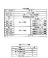
このような要求に応えるため、日本の地上デジタル放送方式では、図51に示すように有効シンボル期間長が異なる3種類のモード、及び各々のモードに対して4種類のガード期間比(有効シンボル期間長に対するガード期間長の比率)を用意している。以下ではこの計12種類の組み合わせを伝送モードと呼ぶ。このうち例えば、モード3のガード期間比1/8とモード2のガード期間比1/4とでは、ガード期間長はどちらも等しく126μ秒となっている。
【0015】
放送事業者の中継局の配置が決まると、各々の中継局からの放送波がサービスエリア内の受信点に到来するまでの時間差の最大値を見積もることができ、その数値から必要なガード期間長が決定される。この数値は各々の中継網毎に異なるため、地域あるいは放送事業者等によってガード期間長及びそれに伴い有効シンボル期間長が異なる可能性がある。
【0016】
また、中継局によって決定されるガード期間長が例えば前述の126μ秒である場合、放送事業者はモード3でガード期間比を1/8とするか、あるいはモード2でガード期間比を1/4とするかを選択することが可能である。このとき、HDTV映像を放送する番組では、伝送容量を稼ぐためにモード3のガード期間比1/8を使用し、移動体向けのサービスを放送する番組では、高速な移動体に対しても安定してサービスを提供するためにモード2のガード期間比1/4を使用するといったように、番組のサービス内容によってこれら二つの伝送モードを切り替えることも可能である。
【0017】
さらに放送サービス開始後、中継局の増設によって中継局間距離が縮まり、前述の時間差が小さくなると必要なガード期間長も短くなるが、ガード期間は元々情報の伝送には不要な冗長期間であるため、周波数資源の有効利用の観点から考えると、当然ガード期間長も必要最低限な長さに変更される。
【0018】
このように有効シンボル期間長とガード期間比の組み合わせで表される伝送モードは、地域あるいは放送事業者によって異なる可能性があるとともに、ある一つの放送事業者に関しても時間的に変化する可能性がある。
【0019】
一方、受信側におけるOFDM信号の復調処理は、受信信号から復調に必要な期間のみを切り出し、その信号に対して高速フーリエ変換(以下、FFT(Fast Fourier Transform))を施すことによって多重伝送されたキャリアを分離した後、各々のキャリアの変調方式に応じた検波処理を行うもので、その処理過程においては有効シンボル期間長及びガード期間比といった伝送モードが必須の情報となる。
【0020】
そこで、受信信号の伝送モードが既知でない場合に、受信信号自体から信号処理によって自動的に前述の伝送モード情報を取得する方法が、特許公報第2863747号あるいは特許公報第2879034号等に開示されている。
【0021】
これらの文献に開示されている従来技術は、OFDM信号のガード期間が有効シンボル期間の後部の信号を巡回的に複写したものであることを利用して、受信信号と受信信号を想定される有効シンボル期間長だけ遅延した信号との相関を算出し、この相関信号の波形を解析することで、有効シンボル期間長及びガード期間長を判定するものである。
【0022】
また従来より、インターネットなどの通信ネットワークを利用した商品の購入など各種の電子商取引が行われている。このような電子商取引では、例えばホームページに取引対象となる商品を掲載する。ユーザは自己の端末からインターネットなどを介し、そのホームページに接続し、購入しようとする商品を選択すると共に、自己を特定するユーザ情報を入力する。
【0023】
そしてクレジット番号の入力や、決済期間におけるIDの入力や、代金引換等の決済方法を指定する。ホームページの運用機関(センタ)は、このような入力の完了をもって商品の発注を行い、発注を受けた業者が商品をユーザに届けると共に、指定された決済方法で料金の支払いを受ける。
【0026】
【発明が解決しようとする課題】
また上述した通信ネットワークを利用した電子商取引においては、セキュリティの確保や決済の煩雑さが問題となる。セキュリティの点では、例えばクレジットカードを利用した場合には偽造等の不安がある。また決済の点では、簡単な作業で決済を行おうとするとセキュリティの信頼性が低下する。そしてセキュリティと決済の容易さを実現しようとすると、システム構成が大型化する問題がある。
【0027】
そこで本発明は、上記の問題を解決し、ユーザーの要求に即応して所望の情報を提供すること、及び放送事業者が番組のサービス内容によって伝送モードを切り替える場合にも、中断することなくユーザーに情報を提供することを可能とするOFDM信号伝送システムを提供することを目的とする。
【0028】
また本発明は、セキュリティの信頼性と決済の容易さを両立し得る簡易な構成の電子商取引システムを提供することを目的とする。
【0033】
【課題を解決するための手段】
本発明の携帯端末は、受信手段と、バーコード形成手段と、表示手段とバーコード読取装置からの光又は信号を検出する検出手段を具備し、前記バーコード形成手段が前記受信手段で受信されたデータを複数のバーコードに変換し、前記表示手段が、前記複数のバーコードを順次表示すると共に、前記バーコードの特定部で、前記バーコード読取装置が前記複数のバーコードの順序又は総数を識別できる情報を表示し、前記検出手段の検出結果から前記バーコード読取装置が現在表示されているバーコードの読取が完了したか否かを判断し、完了したと判断するとき、バーコードの表示を切り替える携帯端末。
【0034】
この構成により、受信信号に応じたバーコードを表示できるので、例えば電子商取引に利用すれば、容易に決済を行うことができるようになる。また携帯端末がバーコードを生成するので、バーコード自体を受信する場合に比べ、受信する必要があるデータのサイズが小さくて済む。
また、この構成により、バーコードで表示すべきデータ量が大きいときに、バーの密度を上げることなく大容量のデータを複数バーコードで表示できる。この結果、誤認識なく、大容量の表示バーコードデータを読み取ることができるようになる。
また、この構成により、検出手段の検出結果に連動させてバーコードの表示を切り替えるようにすれば、携帯端末利用者の操作無しに、バーコード読取装置の読み取り動作に好適に連動して自動的にバーコード表示が切り替わるようになる。
また、この構成により、バーコード読取装置のバーコード読み取り時に、例えば先頭のバーコードではなく、2番目のバーコードしか読み取れなかった場合でも、表示順番号に関連付けてバーコード読取装置に読み取った情報を蓄積しておき、次々と表示順番号を検出して、表示総数分を読み取るまで読み込むことができる。この結果、ランダムなバーコードの部分的な読み込みが可能となるので、全データの読み込み時間を短縮化できる。
【0038】
本発明の携帯端末は、前記バーコード形成手段が前記受信手段で受信されたデータを1次元バーコードと2次元バーコードとを形成する構成を採る。
【0039】
本発明の携帯端末は、前記表示手段は、主表示部と前記主表示部より解像度が高い副表示部とを有し、前記主表示部は前記2次元バーコードを表示し、前記副表示部は、前記1次元バーコードを表示する構成を採る。
【0040】
この構成により、受信信号に応じたバーコードを表示できるので、例えば電子商取引に利用すれば、容易に決済を行うことができるようになる。また副表示部を設け、当該副表示部にバーコードを表示するようにしたので、バーコードが表示されている間でも、主表示部には所望の画像を表示できるので、利便性が良い。
また、この構成により、詳細なバーを表示できるので、表示面積が小さくても、バーコードによる情報量の減少を抑制できる。
また、この構成により、2次元バーコードによる表示データ量は、1次元バーコードによる表示データ量よりも大きいので、例えば副表示部に表示する1次元バーコードでは表示しきれないような、または全て表示するためには長時間かかるような大容量のデータをバーコード表示要求された場合には、選択的に主表示部に2次元バーコードを表示することで、短時間で大容量のデータをバーコード表示できるようになる。
【0043】
本発明の携帯端末は、主表示部はカラーフィルタ層を含み、前記副表示部はカラーフィルタ層を含まない構成を採る。
【0044】
この構成により、副表示部にバーコード読み取りのための光を照射したとき、どの画素を通過した反射光も同じ減衰しか受けないため、高い密度のバーでも誤認識されることが無くなる。
【0045】
本発明の携帯端末は、前記バーコード形成手段は、前記受信手段で受信されたデータを複数のバーコードに変換し、前記表示手段は、前記複数のバーコードを順次表示する構成を採る。
【0046】
この構成により、バーコードで表示すべきデータ量が大きいときに、バーの密度を上げることなく大容量のデータを複数バーコードで表示できる。この結果、誤認識なく、大容量の表示バーコードデータを読み取ることができるようになる。
【0051】
本発明の携帯端末は、前記表示手段は、前記データの大きさに応じて、前記複数のバーコードを順次表示するときの表示切り替えタイミングを選定する構成を採る。
【0052】
この構成により、例えば表示すべきデータ量が多いときには2次元バーコードの更新タイミングを速くし、表示すべきデータ量がそれほど多くないときには2次元バーコードの更新タイミングを遅くしまたは更新せずに、1次元バーコードのみを更新するといった処理を行うことにより、データ量に応じたバーコード表示を行うことができるようになる。
【0053】
本発明の携帯端末は、前記バーコード形成手段は、前記データを複数の1次元バーコードと複数の2次元バーコードに変換し、前記表示手段は、前記副表示部に表示される前記1次元バーコードと前記主表示部に表示される前記2次元バーコードの単位時間当たりの表示情報量が同じとなるように、前記複数の1次元バーコードの表示切り替えタイミングと前記複数の2次元バーコードの表示切り替えタイミングとを選定する構成を採る。
【0054】
この構成により、1次元バーコードも2次元バーコードも単位時間当たりの同じ容量を表示できるようになるので、バーコード読取装置が1次元センサを用いるバーコード読取装置でも、2次元センサを用いるバーコード読取装置でも読み取り可能となる。この結果、どのタイプのバーコード読取装置でも読み取り可能となるので、汎用性を高めることができる。
【0055】
本発明の携帯端末は、前記バーコード形成手段が複数のバーコートを形成する場合、前記表示手段は、各バーコード表示期間の間に所定期間の無表示期間を挟んで前記複数のバーコード表示を行う構成を採る。
【0056】
この構成により、バーコード読取装置の誤認識を抑制できる。
【0057】
本発明の携帯端末は、バーコード表示期間を無表示期間よりも長くなるように選定する構成を採る。
【0058】
この構成により、連続して表示される先のバーコードと次のバーコードの間の時間的なクロストークによる読み取りエラーが大幅に減少される。
【0059】
本発明の携帯端末は、前記データがすくなくとも第1のデータと第2のデータを含む場合、前記バーコード形成手段は、前記第1のデータを複数のバーコードからなる第1のバーコード群に変換し、前記第2のデータを複数のバーコードからなる第2のバーコード群に変換し、前記表示手段は、前記第1のバーコード群と前記第2のバーコード群を順次表示すると共に、前記第1のバーコード群と前記第2のバーコード群の間の前記無表示期間を前記第1また第2のバーコード群内の前記無表示期間よりも長くする構成を採る。
【0060】
この構成により、バーコード読取装置がバーコード読み込み時に無表示期間の時間を測定すれば、各情報の先頭のバーコードを検出できるので、読み取りデータの先頭データの同期検出を容易に行うことができるようになる。
【0063】
本発明の携帯端末は、バーコード表示スイッチをさらに具備し、当該バーコード表示スイッチがオンされた場合、予め設定されたパスワードの入力を要求し、正しいパスワードが入力されなかったときにはバーコードを表示しない構成を採る。
【0064】
この構成により、携帯端末の利用者以外の第3者はパスワードを知らないので、例えばこの携帯端末によるバーコード表示を電子商取引の認証として用いた場合の携帯端末の盗難による誤認証を未然に防止できる。
【0065】
本発明の携帯端末は、暗号処理手段をさらに具備し、前記受信手段が受信したデータを前記暗号処理手段が暗号化し、前記バーコード形成手段は前記暗号処理手段の出力をバーコードに変換する構成を採る。
【0066】
この構成により、例えば携帯端末の利用者の意志に反して第3者がバーコードを不正に読み取ったとしても、暗号鍵がなければバーコードの情報を復号できないので、セキュリティを向上させることができる。
【0067】
本発明の携帯端末は、ローカル無線通信手段をさらに具備し、前記バーコード形成手段は、前記受信手段が受信したデータの中から、前記ローカル無線通信手段が受信した識別情報が示すデータを検索し、検索されたデータをバーコードに変換する構成を採る。
【0068】
この構成により、携帯端末の利用者が選択操作しなくても適当なバーコードを表示できるので、例えば電子商取引に利用すれば、容易に決済を行うことができるようになる。
【0112】
【発明の実施の形態】
以下では本発明の実施の形態について図面を用いて説明する。
【0113】
なお、ブロック図中の各々のブロックの動作に必要なクロックや制御信号等は、本発明の動作を説明するために必要なものを除いては、図面が煩雑になるのを避けるために省略している。
【0114】
(1)第1の実施の形態
図1は、本発明の第1の実施の形態におけるデジタル放送受信装置10Aの構成を示すブロック図である。
【0115】
本実施の形態は、地域あるいは放送事業者等によって伝送モードは異なるが、番組単位というように短時間的に伝送モードは変化しない場合において、主に家庭内等の固定受信環境での利用を想定するものである。
【0116】
図1において、アンテナ101は、デジタル放送信号をチューナ102の入力に供給する。このチューナ102は、アンテナ101から供給されたデジタル放送信号からユーザーが所望するチャネルの信号を選択し、無線周波数帯から基底周波数帯に周波数変換するもので、その出力はOFDM復調部103の入力に供給される。OFDM復調部103は、基底周波数帯のデジタル放送信号に対して復調及び誤り訂正等の処理を施すことにより、伝送情報系列を再生するもので、その出力は情報源復号化部104の入力に供給される。
【0117】
ここで一般的には、伝送情報系列はMPEG2(Moving Picture Experts Group 2)のトランスポートストリーム(以下、TS(Transport Stream))といった形式のものであり、その中には高能率符号化(圧縮)された映像情報や音声情報、及びデータ等が多重されている。
【0118】
情報源復号化部104は、伝送情報系列を映像情報、音声情報、及びデータに分離し、高能率符号化された映像情報及び音声情報を各々復号した後、出力部105の入力に供給するとともに、データを情報バス110を通じてCPU(Central Processing Unit)107に供給する。出力部105は、復号された映像及び音声、あるいはCPU107からのメッセージ等をユーザーに対して提示するものである。
【0119】
入力部106は、ユーザーからの指示を受け、その内容をCPU107に伝達するものである。CPU107は、入力部からのユーザー指示等に基づいて、制御バス109を通じて各ブロックを制御する。またCPU107は、情報バス110を通じて、情報源復号化部104において分離されたデータを受け取ったり、ユーザーへ提示するメッセージ等を出力部105へ出力する。蓄積部108は、本デジタル放送受信装置10Aが動作するために必要な情報を蓄積するものである。
【0120】
ここで入力部106は、本デジタル放送受信装置10Aそのものが備えるボタン等のみならず、外部のリモコン等が備えるボタンやリモコンと本体とのインターフェースをも含む。
【0121】
図2は、図1におけるOFDM復調部103の内部構成例であり、チューナ102の出力はOFDM復調部103内部の直交検波部1031の入力に供給される。直交検波部1031は、基底帯域のデジタル放送信号を直交検波することにより、同相軸(以下、I(In phase)軸)信号と直交軸(以下、Q(Quadrature phase)軸)信号とからなる複素数信号に変換するもので、その出力はガード期間除去部1032に供給される。ガード期間除去部1032は、制御バスインターフェース(I/F)部1037からのガード期間長に関する情報に基づいて、直交検波部1031の出力からガード期間を除去するもので、その出力は高速フーリエ変換(以下、FFT(Fast Fourier Transform))部1033の入力に供給される。
【0122】
FFT部1033は、制御バスI/F部1037からの有効シンボル期間長に関する情報に基づいて、ガード期間が除去された信号をFFTすることにより、多重伝送されたキャリアを分離するもので、その出力は検波部1034の第一の入力及び復調情報復号部1036の入力に供給される。
【0123】
検波部1034は、第二の入力から供給される復調情報(各々のキャリアの変調方式)に基づいて、第一の入力から供給される各々のキャリアに検波処理を施すもので、その出力は誤り訂正部1035の第一の入力に供給される。誤り訂正部1035は、第二の入力から供給される復調情報(時間インターリーブの深さや誤り訂正の符号化率等)に基づいて、第一の入力から供給される検波結果に誤り訂正処理を施すもので、その出力はOFDM復調部103の出力として情報源復号化部104の入力に供給される。
【0124】
復調情報復号部1036は、FFT部1033の出力から復調情報を伝送するキャリアを抽出し、それに対して検波/誤り訂正処理を施すことにより、復調情報を復号するもので、その出力は検波部1034及び誤り訂正部1035の第二の入力に供給される。
【0125】
制御バスI/F部1037は、制御バス109を通じて伝達されるCPU107からの制御情報を解釈し、ガード期間除去部1032やFFT部1033にガード期間長や有効シンボル期間長に関する伝送モード情報を供給する。
【0126】
実際には、検波部1034等のブロックでも動作に必要な制御信号を生成するために伝送モード情報を使用する場合があるが、図2では図が煩雑になるのを避けるために省略している。また、OFDM復調部103が動作するためには、キャリア周波数同期やサンプリング周波数同期、及びシンボル同期やフレーム同期といった同期処理を行なう必要があるが、ここでは同様の理由で省略している。
【0127】
ここで日本の地上デジタル放送方式では、復調情報をTMCC(Transmission and Modulation Configuration Control)と呼ばれる信号を用いて伝送しており、その内容を図3に示す。
【0128】
次に、本実施の形態におけるデジタル放送受信装置の動作について図面を用いて説明する。本デジタル放送受信装置はその動作状態として、少なくともプリセットモードと視聴モードとを備える。
【0129】
図4は、CPU107の動作を示すフローチャートであり、(a)はプリセットモードにおける動作を示し、(b)は視聴モードにおける動作を示す。
【0130】
プリセットモードでは、まず、入力部106より現在地を特定するための情報を取得する(ステップS1)。次に、特定された現在地に対応する選局情報の先頭アドレスA及び情報数nを取得し(ステップS2)、入力部106が備えるボタン0から(n−1)に、選局情報のアドレスAからA+(n−1)を順に割り付ける(ステップS3,S4,S5,S6)。
【0131】
ここで、現在地を特定するための情報としては、住所、郵便番号、電話番号等が用いられ、蓄積部108には、それらの情報と各々の地域に対応する選局情報の先頭アドレス及び情報数とを関連付ける情報が予め蓄積されており、CPU107はその情報を参照することにより、現在地に対応する選局情報の先頭アドレス及び情報数を取得することができる。
【0132】
視聴モードでは、まず、入力部106よりプリセットモードにおいて選局情報アドレスが割り付けられたボタンjの入力を取得する(ステップS11)。次に、ボタンjに割り付けられたアドレスA+jにアクセスし(ステップS12)、蓄積部108よりアドレスA+jの選局情報を取得する(ステップS13)。そして、チューナ102へ周波数情報Fjを伝達し(ステップS14)、OFDM復調部103へ伝送モード情報Mjを伝達する(ステップS15)。
【0133】
図5は、蓄積部108の内容、及び入力部106が備えるボタンへの割付の一例を示す。図に示すように各々のアドレスには、選局情報として、周波数情報及び伝送モード情報が格納されている。
【0134】
以上の構成により、本実施の形態の構成によれば、ユーザーが所望の放送局を選択してから、デジタル放送信号を受信し、その受信信号から伝送モードを判定する必要がないため、ユーザーの要求に即応して所望の情報を提供することが可能となる。
【0135】
なお以上では、蓄積部108に選局情報を蓄積する方法については特に説明しなかったが、これは製造時等に予め蓄積しておく方法でも良く、選局情報を随時更新する方法でも良い。後者の方法を用いると、放送サービス開始後、中継局の増設によって中継局間距離が縮まり、ガード期間長が変更されるといったように、ある程度長期的な伝送モードの変化に対応することが可能となる。
【0136】
また、新たな選局情報を入手する方法としては、デジタル放送信号中の伝送情報系列に選局情報を多重する方法、別途通信手段を設け通信回線経由で入手する方法、あるいは記録媒体を介して入手する方法等を利用することができる。
【0137】
(2)第2の実施の形態
図6は、本発明の第2の実施の形態におけるOFDM信号伝送システムの構成を示すブロック図である。図6において、図1と同一の符号を付した構成要素は第1の実施の形態と同じ動作を行う。
【0138】
本実施の形態は、地域あるいは放送事業者等によって伝送モードは異なるが、番組単位というように短時間的に伝送モードは変化しない場合において、主に自動車や携帯等の移動受信環境での利用を想定するものである。
【0139】
また本実施の形態は、全地球的測位システム(以下、GPS(Global Positioning System))を用いて現在地を特定する以外は、第1の実施の形態と同様の動作を行うものである。
【0140】
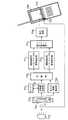
図6において、デジタル放送受信装置10BのGPS用アンテナ111は、GPS衛星20A、20B、20Cからの信号をGPS処理部112の入力に供給する。GPS処理部112は、GPS衛星20A、20B、20Cからの信号中に含まれる擬似ランダム符号を用いて各々の衛星からの信号の到来時間を測定することにより、各々の衛星との距離を求め、三角測量の原理に基づいて現在地を特定する。CPU部107は、第1の実施の形態において説明したプリセットモードにおいて、GPS処理部112が特定した現在地を使用する。
【0141】
以上の構成により、本実施の形態の構成によれば、ユーザーが所望の放送局を選択してから、デジタル放送信号を受信し、その受信信号から伝送モードを判定する必要がないため、ユーザーの要求に即応して所望の情報を提供することが可能となることに加え、現在地が刻一刻変化するような移動受信環境においても、GPSを用いることにより常に現在地を特定することができるので、現在地を特定するための情報の入力を、移動に応じて頻繁に行う必要がなくなる。
【0142】
(3)第3の実施の形態
図7は、本発明の第3の実施の形態におけるOFDM信号伝送システムの構成を示すブロック図である。図7において、図1と同一の符号を付した構成要素は第1の実施の形態と同じ動作を行う。
【0143】
本実施の形態は、第2の実施の形態と同様に、地域あるいは放送事業者等によって伝送モードは異なるが、番組単位というように短時間的に伝送モードは変化しない場合において、主に自動車や携帯等の移動受信環境での利用を想定するものである。
【0144】
また本実施の形態は、セル方式による移動通信システムにおける位置登録機能を用いて現在地を特定する以外は、第1の実施の形態と同様の動作を行うものである。
【0145】
セル方式による移動無線通信システムとは、サービスエリアを多数のセルと呼ばれる小さなエリアに分割し、それぞれに基地局を設置して、ユーザーの移動にあわせて追跡接続するシステムである。このシステムでは、ユーザーが複数のセルにまたがって移動するため、移動機がどのセルに存在するかを常に把握している必要がある。また、セルが変わってもスムーズに通信を継続するための欠かせない制御技術として、位置登録機能を備えている。
【0146】
位置登録において移動機は、基地局から位置情報を取得し、その情報を自機内に登録するとともに、ネットワークにも通知する。その後、位置変更を検知した場合、移動機は自機内の位置登録を更新するとともに、ネットワークにも通知する。また、移動機の電源オフ後、再び電源をオンにした場合、そのときの基地局からの位置情報を自機内の位置情報と比較し、違う場合は自機内の位置登録を更新するとともに、新しい位置情報をネッワークに通知する。
【0147】
図7において、デジタル放送受信装置10Cの無線通信用アンテナ113は、無線通信基地局30からの信号を無線通信インターフェース(I/F)部114に供給するとともに、無線通信I/F部114から供給される信号を無線通信基地局30へ放射する。無線通信I/F部114は無線通信用アンテナ113から供給される無線通信基地局30からの信号に含まれる位置情報を抽出し、現在地を特定しその情報をCPU107に伝達する。CPU部107は、第1の実施の形態において説明したプリセットモードにおいて、無線通信I/F部114から伝達された現在地情報を使用する。
【0148】
以上の構成により、本実施の形態の構成によれば、ユーザーが所望の放送局を選択してから、デジタル放送信号を受信し、その受信信号から伝送モードを判定する必要がないため、ユーザーの要求に即応して所望の情報を提供することが可能となることに加え、現在地が刻一刻変化するような移動受信環境においても、セル方式の移動無線通信における位置登録機能を用いることにより常に現在地を特定することができるので、現在地を特定するための情報の入力を、移動に応じて頻繁に行う必要がなくなる。
【0149】
(4)第4の実施の形態
図8は、本発明の第4の実施の形態におけるOFDM信号伝送システムの構成を示すブロック図である。図8において、図1及び図7と同一の符号を付した構成要素は第1の実施の形態及び第3の実施の形態と同じ動作を行う。
【0150】
本実施の形態は、地域あるいは放送事業者等によって伝送モードが異なるとともに、番組単位というように短時間的に伝送モードが変化する場合において、主に自動車や携帯等の移動受信環境での利用を想定するものである。
【0151】
また本実施の形態は、伝送モード情報を含む番組情報を、放送とは別回線を用いて伝送し、選局時にその情報を使用するものである。
【0152】
図8において、番組情報配信センター50は、放送局60から通信回線40を通じて、番組情報を取得/蓄積し、デジタル放送受信装置10Dからの要求にしたがって、前記番組情報を配信する。
【0153】
一方、デジタル放送受信装置10Dは、第1から第3の実施の形態とは異なり、動作状態としてプリセットモードを備えることなく、ユーザーの所望する情報を提供することができる。
【0154】
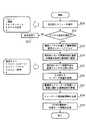
図9は、デジタル放送受信装置10D中のCPU107の動作を示すフローチャートである。
【0155】
まず、出力部105を通じてユーザーにメニューを提示する(ステップS20)。そしてユーザーがデジタル放送を所望した場合(ステップS21,S23)、無線通信I/F部114及び無線通信用アンテナ113を用いて、番組情報配信センター50への番組情報配信の要求を送信する(ステップS23)。このとき、実施の形態3において説明した位置登録機能を用いて、要求とともに現在地を通知する。
【0156】
番組情報配信センター50は、無線通信基地局30及び通信回線40を通じて、デジタル放送受信装置10Dからの配信要求及び現在地を受け取ると、その現在地で受信可能な放送局が提供する番組に関する情報を、通信回線40及び無線通信基地局30を通じて、デジタル放送受信装置10Dへ配信する(ステップS23)。
【0157】
デジタル放送受信装置10D中のCPU107は、番組情報配信センター50からの番組情報を、無線通信用アンテナ113及び無線通信I/F部114を通じて取得し、その情報を蓄積部108へ蓄積する(ステップS24)とともに、出力部105を通じて現在地において受信可能な番組リストをユーザーへ提示する(ステップS25)。
【0158】
そして、ユーザーが上記リストの中から所望の番組を選択すると(ステップS26)、蓄積部108より、上記番組に対応する選局情報を取得し(ステップS27)、チューナ102へ周波数情報を伝達し(ステップS28)、OFDM復調部103へ伝送モード情報を伝達する(ステップS29)。
【0159】
図10は、番組情報の内容の一例を示す。この例では番組情報として、各々の番組に対して、コンテンツ情報としてタイトル及びジャンルを、選局情報として周波数情報及び伝送モード情報を、時刻情報として開始時刻及び終了時刻を含んでいる。
【0160】
以上の構成により、本実施の形態の構成によれば、プリセット動作を行うことなく、ユーザーが所望する番組を提供することが可能となることに加え、現在地が刻一刻変化するような移動受信環境においても、セル方式の移動無線通信における位置登録機能を用いることにより常に現在地を特定することができるので、現在地を特定するための情報の入力を、移動に応じて頻繁に行う必要がなくなる。
【0161】
なお、番組情報を現在の番組から、24時間以内あるいは1週間以内のように、ある程度先までの予定を含めて配信するようにし、デジタル放送受信装置10Dがその内容を蓄積部108に蓄積すれば、ユーザーがあらかじめ所望の番組を予約しておき、開始時刻になれば自動的に提示するといった動作も可能となる。
【0162】
また、本実施の形態では番組情報として選局情報を番組に対して関連付けることを説明したが、地域あるいは放送事業者等によって伝送モードは異なるが、番組単位というように短時間的に伝送モードは変化しない場合を想定すると、番組情報配信センター50は、選局情報を放送事業者に対して関連付けた情報を配信し、デジタル放送受信装置10Dは、第1から第3の実施の形態と同様に、その情報を入力部106のボタン等に割り付けることも可能である。
【0163】
さらに、このような割り付けを行った後、伝送モードが変化したり、あるいは移動により現在地が変化した場合には、デジタル放送受信装置10Dは、受信不可となった旨を出力部105を通じてユーザーに通知するとともに、再び番組情報配信センター50に情報の配信を要求し、新たなリストの提示、及び割り付ける情報の更新を行うことにより、ユーザーに対する利便性の向上を図ることも可能である。
【0164】
(5)第5の実施の形態
第5の実施の形態においては、CPUで構成される伝送情報管理部が行う伝送情報のマネジメントについて説明する。伝送情報の頻度管理、使用後の経過時間等の時間管理、電界強度管理、チャンネルの地域識別サービス内容等の管理と予測や、パターン化した情報による情報圧縮等について詳しく述べる。伝送情報は形態電話の基地局からの送信データもしくは、テレビ放送局からの送信データのいずれかもしくは双方に含まれるが、実施例では携帯電話基地局から送信した場合の例を用いて説明する。
【0165】
(5−1)全体構成
図11は、テレビ受信型携帯電話501と地上波テレビ局502と携帯基地局503との関係を示す全体図である。地上波テレビ局502からは、下りの一方向である放送信号504が携帯電話501に送られ、この放送信号504の特定チャンネルのデータの1部を部分受信する。また、放送信号504は、固定アンテナ514をもつ固定受信機すなわちデジタルテレビ受信機505にも送られる。
【0166】
(携帯受信)一方、テレビ受信型携帯電話501は、自分の近傍の1つもしくは、複数の携帯基地局503,503a,503bからの電波である下り信号506,506a,506bを受信するとともに、携帯基地局503,503a,503bのいずれかの1つもしくは複数局へ、上り信号507,507a,507bを送信する。そして携帯基地局503は携帯制御部510を介して公衆網511に接続される。特定の携帯電話サービス会社においては、サーバー512を介してインターネット513に接続される。
【0167】
(固定局受信)前述のように、家庭用テレビのように感度の高い固定アンテナ514をもつデジタルテレビのテレビ受信器505でも受信する場合は、前述の部分放送の受信ではなく特定のチャンネルの中の全部のデータを受信する。一部のテレビ受信機505は電話回線を介して地域の固定電話局515に接続され、公衆網511を介してインターネット513に接続可能である。
【0168】
前述のデジタルテレビ放送を携帯電話501で受信する場合と、固定されたテレビ受信機505で受信する場合とでは受信条件に大きな違いがある。テレビ受信型携帯電話501で受信する場合は、受信機が移動する点である。前述のSFN(Single Frequency Network)のチャンネル放送を受信する場合、図12に示すように受信機が次々と移動し、次の放送局のサービスエリアへ移っても全く同じ情報をもつ同じ周波数のテレビ電波を受信するため、テレビ受信に支障はなく、移動してもシームレスに受信できるため、問題は起こらない。
【0169】
しかし、SFNでないチャンネルの放送を受信する場合は、受信機がポジション1(図12)からポジション5まで移動する過程において、従来の方法ではポジション2からポジション3の間のある地点で、電界強度低下のため第1テレビ局502の電波が受信できなくなる。
【0170】
そこでテレビ受信型携帯電話の使用者はチューナで周波数を切り替え、放送しているチャンネルを探そうと操作を試みる。ようやく第2テレビ局502aの存在を知り、受信しようとする。しかし放送がデジタルテレビ放送の場合、アナログ放送と違い周波数を合わせただけでは受信できない。ガードタイムやエラー符号化ゲイン等の伝送情報のパラメータを一致させないと、物理層を受信できない。このため、従来方式のテレビ受信型携帯電話の場合は、パラメータを色々と変更して、総あたり方式でどのパラメータが適しているかを探そうとする。
【0171】
パラメータは数十種類から数千種類の組み合せがある。このため、パラメータマッチングに時間を要する。受信信号の第1階層の復調情報を得た後は、第2以上の階層を復調できるので情報を得ることが可能となる。このようにパラメータ決定に時間を費やすため、周波数を含めるとこの間、例えば数秒から最大〜十数秒間テレビ受信信号の出力ができなくなる。受信できたチャンネルが使用者の所望するサービスを放送していなかった場合は、別のチャンネルに切り換えて好みのサービスのチャンネルを探すことになる。この場合も同様にパラメータの決定に時間を費やすため、さらに余分に時間が必要となる。
【0172】
本発明では、携帯基地局503の下り信号506の中から少なくとも基地局IDを受信し、基地局IDから位置情報を得たり、位置情報からテレビ放送の変調信号を復調するためのパラメータを含む伝送情報を得て復調する。もしくは、予め携帯電話に記録された対応リストである伝送情報管理データベースを用いて得られた基地局IDに対応する、地域のテレビ放送局の伝送情報を読み出すことにより、チャンネルの復調時の手順をスキップできる。従って、チャンネルの受信時間やチャンネルの切り替え時間を短縮することができる。
【0173】
ここで図13に携帯電話の基地局503の構成を示す。携帯基地局アンテナ516と基地局送受信回路517とATM(Asynchronous Transmission Mode)等で回線接続されたRNC(Radio Network Controller)と呼ばれる通信制御部518と、バックボーン519で接続されたPDSL(パナソニック デジタル ソフト ラボレタリ)520とを有する。これらは携帯電話の通信において必要なブロックである。
【0174】
携帯基地局503からは図14に示すようなデータが発信される。すなわち、図14(a)の送信データの待ち受けモード時の基本情報である携帯電話用データ522や、図14(b)の通話モード時の基本情報である携帯電話用データ523には、基地局ID521又は基地局番号521が含まれる。従って基地局IDは全ての携帯電話のサービスエリアで受信可能であり、この基地局IDはテレビ受信用の補助情報として使用できる。
【0175】
また、本発明に対応している基地局503はテレビ受信に必要なテレビ受信用の伝送情報データ524の一部もしくは全部を送信する。これらの伝送情報は、テレビ放送信号の中に他の放送局の伝送情報を送信してもよい。この場合、一旦テレビ受信に成功すると他局の伝送情報を入手できるので、基地局送信と同様の効果が得られる。しかしテレビ受信が一旦中断すると基地局の情報が必要となる。
【0176】
(5−2)第1,第2伝送情報の説明
図14のテレビ受信用データ524を説明する。図15はこのテレビ受信用データの具体的な内容をOFDM方式の日本のデジタルテレビ放送規格であるISDB−T規格に準じて示した図である。DVB規格等のOFDM方式のテレビ放送規格も同様のパラメータをもつ。
【0177】
図14(a)は携帯電話の待ち受けモード時の送信データであり、第1の耐性の強いチャンネルを用い、携帯電話用データ522、すなわち基地局を識別するための基地局ID521と、空いている携帯電話用の通信チャンネルのデータを送信する。前述のように本発明に対応した携帯基地局では、これに加えて、デジタルテレビ放送の同調復調に必要なテレビ受信用データ524を送信する。
【0178】
テレビ受信用データ524には、現在送信中のテレビ放送局のチャンネルを示す送信情報528が含まれる。送信情報528には、現在放送中の全チャンネルのチャンネルIDが含まれる。送信中のチャンネル527は、固定受信局のみならず、電車や自動車においても受信され、利用される。Τモード携帯電話向け専用なら部分放送をサービス中の放送局のチャンネルIDに限定すれば、情報量を減らす効果がある。
【0179】
1つの例としてISDB−T規格の場合を示す。図16(a)に示すように、6MHz又は8MHzの1つの放送帯域で、同じ伝送耐性で高解像度のテレビ放送であるHD放送1チャンネル又は、通常解像度のテレビ放送であるSD放送4〜5チャンネルの放送データ528を送るので、送信中のチャンネル527でよい。
【0180】
しかし、実施の形態では、図16(b)のように、13セグメントのうち、1つもしくは2つの特定の部分セグメント529を、他の一般セグメント530より耐性を強くする。例えば、変調方式を一般セグメントには64QAMを用いるのに対し、特定の部分セグメントにはQPSKを用いたり、FFTサイズを前者には8Kを用いるのに対して後者には2Kを用いる等のパラメータを変えて情報伝送効率を下げて耐性を強くする。
【0181】
この階層型放送を本実施の形態では“部分伝送”もしくは“部分放送”と呼ぶ。部分セグメント529は耐性が強いパラメータで放送されているため、携帯電話のアンテナ531(図17)のような小型のアンテナでも受信できる。一方で、部分放送の場合使用周波数帯が狭くかつ伝送効率が下がるため伝送データ容量は数百Mbpsから約1Mbps強となり大巾に減る。
【0182】
しかし携帯電話のようなモバイル機器の場合、表示画面が1インチから数インチで小さいことと数十Kbpsから数百Kbpsのような低い伝送レートで圧縮効率がよいMPEG4やウェーブレット方式を採用することにより視聴に支障のない画質の画面を提供することが可能である。
【0183】
また、図16(c)のように単独の1セグメント532や3つのセグメントを用いたデータ放送がISDB−Tで定義されているがこれらも“部分伝送”と同様、携帯受信に適している。本明細書ではこれらのデータ放送も“部分伝送”に含めて呼ぶ。
【0184】
図14に戻り、送信情報528の中には、このような移動体受信する携帯電話向けに上述の部分伝送中のチャンネル533のデータが含まれる。放送中のチャンネル番号(以下chと略す)は各国で割り当てられた周波数帯を示すだけである。例えば15chを放送している地域からお互いに干渉しない分だけ離れた別の地域では、別の放送局が15chつまり同一のチャンネルつまり同一の周波数を用い全く別の放送をサービスしている。
【0185】
携帯電話におけるテレビ受信においては移動するため両者を識別する必要がある。そこで、同一chの放送局を識別するための識別情報534を付加する。このことにより、始めて各々の放送局を特定できる。例えば、同じ15chでも地域Aの前者を15−1chと定義し、地域Bの後者を15−2chと定義する。
【0186】
このように同一周波数で地域別に異なる放送局を識別できる識別子を付加して各放送局のチャンネルを定義すれば、同じ周波数帯つまりチャンネルを用いる地域の異なる放送局を互いに識別できる。このため同じチャンネルの放送局の誤認による誤まった伝送パラメータの設定による誤動作を防ぐことができる。
【0187】
また本発明に対応した基地局はチャンネル毎の電界強度情報535を送信する。この情報を受信機側で管理することにより電界の強いチャンネルグループから優先度を高くして受信チャンネルを選択することができるため、より安定した受信が可能である。
【0188】
次に復調するのに必要な伝送情報について図14,図15を用いて詳しく述べる。第1伝送情報526は、図15又は図14に示すように送信するチャンネルを示す送信周波数536,部分放送識別子550,FFTサイズ537,シンボル時間とガードインターバルとの期間の比率を示すガード比538,放送アンテナの送信電力539が含まれる。
【0189】
図15に示すように第1伝送情報526により各種パラメータが放送信号や復調する前に判る。このため1回目のパラメータ設定で、OFDMやPSKでの階層伝送の第1層のデータが復調される。同時に第2層を復調するための復調情報541、例えばISDB−T規格のTMCCデータやDVB規格のTPSデータ等を第1層から復調したデータから取得できる。この復調情報によりすべてのデータを復調することができる。
【0190】
携帯電話や自動車用途のような移動体受信の場合、複数の放送局のサービスエリアを移動するため第1伝送情報526のパラメータが頻繁に変わる。第1伝送情報のパラメータが判らない場合、総当り方式で全パラメーターを設定し、復調を試みるしかない。第1伝送情報の組み合せはISDB−T規格の場合で12通りの組み合せがあるため、第1層のパラメータを確定するのに最大12回の設定を行う必要がある。このため受信データの出力まで時間を要するが、本発明により瞬時に第1層のデータを再生できるという効果がある。
【0191】
この第1層のデータには、第2層以降の階層信号の復調やエラー訂正に必要なパラメータ等が含まれる復調情報541が含まれるので、第1層を復調する第1ステップの後に、復調情報541を復調する第2ステップと、復調情報からパラメータを取り出す第3ステップ以上の3つのステップを経ると、第2層の場合は復調情報541を用いて復調できる。
【0192】
しかし、前述のようにモバイル用途では頻繁に伝送情報のパラメータが変わる。もしこの第2層の復調情報541を事前に知ることができれば、全ての伝送パラメータが入手できるため、さらに高速にデータを復調できる。この、高速化された方式について図14,図15を用いて説明する。図14(a)は待ち受けモード時に携帯基地局から第1伝送情報526と第2伝送情報525の双方を送信する方式である。
【0193】
効果の説明を先に述べる。待ち受けモード時に伝送情報を基地局から送信してくる。このため、上り回線をもたない、つまり送信機能をもたないPDSのような携帯端末や携帯テレビでも、この情報を受信することができるので、初受信時もしくはチャンネル変更時の受信時間が大巾に短縮されるという効果がある。
【0194】
また携帯電話のような送信機能をもつ機器においても日本等の国では電車内や病院内において携帯電話の送信が禁止されているが、そのような場所においてもスイッチで“Τモード”に切りかえておけば送信することなしに伝送情報を受信し入手できるので、携帯電話の放送受信の利用機会が増える。
【0195】
また、携帯電話使用禁止エリアに入る前にΤモードスイッチをオンにすると基地局もしくは、基地局経由で放送局に自分のエリアと利用時間帯と携帯端末IDと呼び出しデータを受信する放送局の放送局IDとを送信する。すると携帯に電話がかかってきた時、放送局経由で放送信号の中に自分の携帯端末IDを送信してくれるので、自分に電話がかかってきたことが検知され、震動モーター等により、本人に通知されるため、殆んど携帯電話の送信なしに、受信通知がなされるというページングの効果もある。
【0196】
本発明の呼び出し方式を含むΤモードにおいては、強い送信用の電波が発信されないため、総合的に携帯電話の送信電波の発信が残り人体への影響を小さくできる効果がある。
【0197】
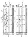
伝送情報のパラメータをパターン化して管理し、情報を圧縮する方法について述べる。図14(a)の第2伝送情報に戻ると、第2伝送情報525には、変調方式551,符号化率552,時間インターリーブ長553のパラメーターが入っており、各チャンネル毎に各パラメータは異なる。具体例を述べると図15の下半分に示すように、ISDB−T規格の場合、変調方式551として、DQPSK,16QAM,64QAMの3通り、エラー訂正用のビタビ等の符号化率552は5通り、時間インターリーブ長553は4通りあり、第2伝送情報のパラメータは60通りの組み合せがある。
【0198】
第1伝送情報のパラメータは、12通りで部分放送識別子550を含めると24の組み合せがあるため全部で、60×24=1440通りの組み合せが考えられる。これを図15の右下にチャンネル毎のパラメータ設定例として示す。しかし、実際のデジタルテレビ放送においては放送局の作業が複雑化するので各放送局はこのうちの特定のパラメータを選ぶと予想できるのでパラメータはパターン化できる。
【0199】
そこで、図17のブロック図と、図18のデータベースリストに示すように伝送情報管理部556は第1伝送情報526の頻度の高い順に例えば16ヶ選び、第1パターン番号554を選び、伝送情報データベースメモリ557に記録しておく。第2伝送情報525も同様にして16通り、つまり4bitのパラメータを選び、データベース559を含むメモリ557に記録しておく。
【0200】
こうすると各放送局には、16×16通り=8bit、つまり1バイトのデータで伝送情報の全パラメータが表現できるため、パターンがこの範囲に収まれば特定の国の中の1000局分でも伝送情報の記録には1KBのメモリー容量の消費でよい。このためメモリ容量の少ない携帯電話においてメモリ容量の消費を削減できるという効果がある。
【0201】
頻度演算と頻度管理は伝送情報管理部556が行い、位置検出部558において放送局の位置を判断し、放送局毎に管理することにより、パラメータのヒット率は高くなる。この伝送情報管理システムの動作ステップについては後で詳しく述べる。
【0202】
次世代の携帯電話の主流となるW−CDMA(Wideband Code Division Multiple Access)方式の場合、日本等のアジアや欧米の国で、同一の携帯電話を用いて通話することができるようになる。図17に示すように本発明のΤモード携帯電話501は国検出部560をもつ。例えば、日本の使用者が欧州や米国に移動した場合、基地局IDの中の国識別情報から国が変わったことが検知できる。この検知信号は伝送情報管理部556に通知されるので、その国の放送規格に合わせての周波数変更や伝送パラメータ、例えば、QPSKやQAMの変調方式やFFTサイズやガード期間化符号化率等の変更を行うことにより、海外でも海外の放送規格のパラメータで送信された放送が受信できる。
【0203】
(5−3)携帯電話の説明
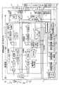
図17のΤモード携帯電話501のブロック図を用いて、携帯電話による伝送情報を含む下り信号の復調について説明する。アンテナ531から受信した信号は共用器561により分離され、フロントエンド562、フィルタ563によりフィルタされ、復調器564により復調される。次にA/Dコンバータ565によりデジタル信号とされ、CDMA信号の拡散信号を戻す逆拡散部566において同期部567の同期信号に基づき、拡散されていたデータが復元される。この信号は検波部568により検波され、データデコーダ569によりビタビ復号され、出力制御部570を経て音声デコーダ571により音声信号とされる。
【0204】
次に切換部572によりスピーカ573に出力されるか、もしくは低域信号を通過させるLPF574を通してイヤホン端子575に出力される。このイヤホン端子にイヤホン576を接続することにより、使用者は受信した音声信号を聞くことができる。本発明ではこのイヤホン576のコード577は、テレビ等の放送の受信用アンテナとして兼用して用いることにより感度を高めている。
【0205】
受信された放送信号は、図17に示すようにテレビ受信部578の切換部579により携帯用アンテナ531で受信された信号とイヤホンコードで受信した信号とで切換えられる。この場合、信号レベル比較部588により比較し放送電波の受信信号の強い方、もしくはC/N値が高い方もしくはエラーレートの低い方を選択し切換えて出力するので、ダイバシティアンテナのように最適な受信信号が得られる。チューナ580において周波数制御部581により特定のチャンネルの周波数の信号に同調させ、復調部582において復調制御部583より、復調に必要な第1伝送情報や第2伝送情報のパラメータ(図15)を受け取り復調する。このOFDMの復調の方法は前に詳しく述べたので省略する。
【0206】
復調された信号はエラー訂正部584において、図15に示すようなビタビ等のエラー訂正パラメーターを用いて、元の信号を復元される。出力部586より出力制御部570を介して映像デコーダ587によりMPGE4やWavelet等の信号を映像信号にデコードし、表示回路589を介して表示部590に映像を表示させる。また放送信号の中に含まれるデータ信号は処理され、出力制御部570から副表示回路591により副表示部592に表示される。このフローは次の実施の形態で説明する。
【0207】
図17の携帯電話の送信時の動作を説明すると、使用者の音声はマイク594より電気信号に変換され音声デコーダ595で圧縮され、チャンネルコーデック596に入力される。一方、使用者がキーボード593を用いてキー入力したデータの方は出力制御部570で処理され、処理された結果のうち、基地局へ送信する必要のあるデータはチャンネルコーデック596へ入力される。
【0208】
このコーデックされた出力信号は1次変調器597によりQPSK等に変調され、拡散部598により周波数帯上に拡散され、ROF599を介してD/Aコンバーター600により、アナログ信号とされ、発振器603をもつ変調器601でさらに変調される。この変調信号は発振器604とミキサー602において混合されパワーアンプ605により増巾されて共用器561を通り、アンテナ531より送信される。以上がΤモード携帯電話501の送信部606の動作である。
【0209】
このように、携帯電話基地局503から送信される基地局IDや放送の受信に必要な受信情報や復調情報をΤモード携帯電話501の受信部607で受信し、これらのデータをテレビ受信部578の伝送情報管理部556へ送る。そして伝送情報データーベース559等のメモリ557のデータを用いて受信データを加工、もしくはそのまま用いて、周波数制御部581のデータにより、チャンネルの周波数の同調を行う。次に復調制御部583からの復調制御信号により、最適パラメータの設定による瞬時の復調、復号化制御部585によるエラー訂正の最適符号化率の設定により、最短の時間で復調されるため、テレビ放送や音楽放送やデータ放送の内容が瞬時に表示されるという著しい効果がある。
【0210】
なお、この効果だけでよいなら図17の送信部606は必要ない。このため、一般の携帯型テレビの場合、本発明の受信部607の追加や伝送情報管理部556を含むテレビ受信部578の構成を採用するだけで同様の効果が得られる。
【0211】
なお、図14(a),(b)に示すように第1伝送情報526と第2伝送情報525を携帯基地局の送信電波を用いて伝送する例を示したが、前述のように各テレビ放送もしくは部分放送のデータ領域にその地域で受信可能な他の放送局のチャンネル番号等の送信情報528や第1伝送情報526や第2伝送情報525を送信してもよい。
【0212】
この場合、図17の下のブロック図の携帯受信機501側のテレビ受信部578で特定のチャンネルを受信している場合は、出力部586から他局の伝送情報が出力される。そのチャンネルのデータの中に、その地域で受信可能な他局のチャンネルの送信情報528(図14)やそれらのチャンネルに関する第1伝送情報526や第2伝送情報525が含まれている。この伝送情報を図17の出力部586より取り出し、そのチャンネルの伝送情報を加えて伝送情報管理部556に入力すれば、伝送情報データベース559に記録される。
【0213】
特定のチャンネルの放送局の番組受信中に他のチャンネルに切り換える場合は、この他局のチャンネルの受信情報を伝送情報データベース559から取り出し、伝送情報管理部556が各部の各パラメータを各々設定し、同調、復調、エラー訂正を行うので1回目のパラメータ設定で、他局のチャンネルを出力部586より出力できる。
【0214】
このためパラメータを知らない場合に比べると他チャンネルへ切り替え時の時間を大巾に短縮できるという効果がある。この場合、現在の放送サービスエリア内の放送局の伝送情報だけでなく、隣接するサービスエリアの放送局の伝送情報を送信することにより、移動受信がより確実となる。
【0215】
この場合、特定の放送局IDの放送局の放送サービスエリアに対応する基地局サービスエリアをもつ基地局IDを対応ずけて送る。このデータを受信機が伝送情報データベース(DB)559に記録する。その後、受信が中断しかつ、移動しても基地局IDがわかれば伝送情報が判明し、復調可能となる。
【0216】
ただし、大きく移動した後の初回の受信時には、その地区の受信用のパラメータが全くわからない。このようにテレビ放送の受信を中断しかつ移動した場合は、携帯電話の基地局の伝送情報が必要となる。
【0217】
ここで復調する場合の3つの方法を述べる。まず、第1の方法を述べる。第1の方法は、最も簡単な構成の図17のテレビ受信部578しかもたない場合を想定し、総あたり式にパラメータを変える方法である。この第1の方法は、低価格の携帯テレビやPDCに適している。
【0218】
第2の方法は、本発明の図17の受信部507を追加する方法である。これにより携帯基地局のIDを受信することができるようになる。本発明では伝送情報管理部556があるので基地局IDからサービス中の放送局がわかる。伝送情報管理部556は、この基地局IDと時間情報部610からの時刻をもとに伝送情報データベース559から基地局IDと現在の時刻に対応する放送局の放送時刻の伝送情報を検索し、該当チャンネルの対応する日時の伝送情報のパラメータをチューナ580、復調部582、エラー訂正部584に送ることにより、移動後でも瞬時に所望のチャンネルの出力を行う。チャンネル変更の場合は、放送信号からダウンロードもしくは受信する伝送情報を用いる。
【0219】
この今述べた第2の方法は、全く携帯基地局とは無関係であるので、放送以外の通信インフラを必要としないという効果がある。また第2の方法は、携帯基地局を利用するが、基地局IDしか使わないので、既存の携帯基地局設備を変更する必要がないという効果がある。本発明の伝送情報送信方式が採用されたとしても、携帯基地局の数は世界中で数万局以上あるため、除々に対応が進んでゆくと予想される。その対応の過程においては、対応してない基地局が多く存在し、その地域においては上述の第2の方法が有効でかつ現実的である。
【0220】
この上述の第2の方法と第3の方法である基地局から伝送情報を受け取る完全対応方式とを、図17の構成で切り替えるためには、基地局ID検出部611が携帯受信信号に基地局IDのみで伝送情報が含まれていないことを検知し、この検知信号を伝送情報管理部556に送る。基地局IDを用いて伝送情報データベース557から基地局IDに対応する放送局の伝送情報を検索し、もしあれば、パラメータを設定することにより放送信号受信する。もしなければ総あたり式にパラメータ設定値を変更して復調する。移動した後の第1回目の放送の受信は時間がかかるが、一旦放送が受信できると他局の伝送情報がダウンロードできるため、チャンネルを切り替えても受信信号の出力は瞬時にできる。
【0221】
この場合、携帯電話の上り回線で特定のWebサイト等へ接続し、その地区の伝送情報の送信を要求し、下り回線で伝送情報をダウンロードしても同様の効果が得られる。
【0222】
(5−4)携帯基地局の説明
次に図13を用いて携帯基地局503の側の構成と動作を説明する。まず全体の構成を述べる。図13の携帯基地局503は携帯電話アンテナ516と送受信回路517とを有し、通信制御部518と専用の通信回路でATM等で接続されている。各地域にある複数の通信制御部518,518a,518bは、伝送容量の大きなバックボーン回線519を介して携帯電話会社564のPDSL520に接続され集中的に制御される。
【0223】
次に本発明のテレビ等の放送受信に必要な伝送情報を送出する機能を付加した構成を述べる。携帯電話用アンテナ516の近傍には、放送受信アンテナ551が設置されており、その地域の放送電波を受信し放送受信部550において受信信号増巾部620において増巾し、チューナ580で同調する。その信号は直交検波部1031を介してガード期間除去部1032,FFT1033,検波部1034,誤り訂正部1035を経てデジタルデータとして出力される。この部分の動作は図2を用いて既に説明しているので省略する。
【0224】
この復調を各チャンネル毎に絶えず行うことにより、同調や復調に必要な最適パラメータの伝送情報を得ることができる。これらのパラメータの一部又は全部を図13の放送受信情報抽出部542が抽出して、放送受信情報付加部547に送出し、その後、送信部621により増巾されて図14(a)(b)に示すように携帯電話の送信信号に混合される。次に基地局アンテナ516からΤモード携帯電話に送信されて、テレビ等の放送の同調・復調情報として用いられる。
【0225】
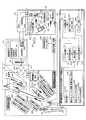
次に伝送情報抽出部542の動作を説明する。まず狭い地域用の情報ブロックである送信情報抽出部543ではまず、増巾部620の出力から増巾率と信号レベルをみて、電界強度535Zを求める。この電界強度と距離を演算し、放送局の送信電力539Zを得る。チュナー部580からは、現在送信中のチャンネル527Zと部分放送中のチャンネル550と送信周波数536Zを得る。ガード期間除去部1032からはガード比538Zを得る。FFT部1033からはFFTサイズ537Zが得られる。復調情報復号部1036からは変調方式551、ビタビ等の符号化率552、時間インターリーブ長553が得られる。以上のパラメータの中から送信情報抽出部543のパラメータを送信情報付加部548に送り、送信アンプ625により増巾して本発明のΤモード携帯電話向けに携帯電話用アンテナ516を介して送信する。第1伝送情報抽出部545及び第2伝送情報抽出部546で構成される広い地域用の情報ブロックである伝送情報抽出部544で抽出されたパラメータは、それぞれ伝送情報付加部549の第1伝送情報部526Z、第2伝送情報部525Zに送られる。次に送信アンプ621を介してΤモード携帯電話向けに送信されるか、もしくは一旦通信制御部518の番組情報を送るための放送用伝送情報処理部560に送られてから、携帯基地局503に送られる。
【0226】
また放送局563は、番組情報送信部562をもち、番組情報と伝送情報を回線を介して放送伝送情報処理部560に送り携帯基地局503を介して、Τモード携帯電話に送信し、番組情報や伝送情報をダウンロードさせることを可能とする。この場合番組情報はサービスエリア内の複数の基地局に全てに同じ内容を送り、伝送情報は基地局ID毎にもしくは放送サービスエリアに対応する基地局IDグループ毎に異なる内容を送る。
【0227】
以上のようにして、携帯基地局毎に携帯用アンテナの近傍にテレビ放送受信アンテナ551を設け、伝送情報のパラメータを各チャンネル毎に得ることにより、本発明の伝送情報受信が基地局単独で可能となる。このため、システムがローカルサイドで完結するためシステム構成が簡単になるという効果が得られる。
【0228】
(5−5)伝送情報マネジメントシステム
伝送情報管理システムの動作モードは複数あるが、各々のモードを図面を用いて説明する。
【0229】
(5−5−1)パラメータの設定
まず、図19のフローチャート図を用いて第1の方法を説明する。まずステップ650aでΤモード携帯電話もしくは、PDA,携帯型テレビのモデル機器の電源スイッチ(SW)が入る。ステップ650bでまず、携帯基地局の下り回線を受信する待ち受けモードに設定される。ステップ650cで下り回線の信号の中の制御情報の中の基地局ID521(図14)を取得する、もしくは/かつメモリ557(図17)に記録する。ステップ650dで下り信号の中に、テレビ等の放送の送信情報528(図14)もしくはかつ第1伝送情報526のデータがあるか、もしくは、上記2つの情報の存在を示す識別子があるかをチェックし、Yesならステップ650eに進み、Noならステップ650jに進み、3つのフラグを立ててステップ650kへ進む。
【0230】
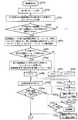
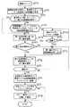
ステップ650dに戻ると、Yesならステップ650eに進み、送信情報528もしくは/かつ第1伝送情報526を取得もしくはかつメモリ557への記録を行う。ステップ650fで下り信号の中に、第2伝送情報525もしくはその存在を示す識別子があるかをチェックする。“No”ならステップ650iで“2”のフラグをつけてステップ650kへ進む。“Yes”ならステップ650gで第2伝送情報を下り回線のデータ中から取得もしくは、取得しメモリ557への記録を行う。ステップ650hではフラグ=“1”とする。ステップ650kでテレビ等の放送の受信を開始せよとの命令、つまりΤモードの命令を受けると、ステップ650mで使用者が前回受信した時に用いた伝送情報のパラメータを用いて受信するかを判断する。使用者の入力がない場合、伝送情報管理部556(図17)が判断する。伝送情報データベース559の中のデータをみて、時間管理を用いて前回その放送局を受信した時間から一定時間以上経過していない場合、もしくは、前回受信した時と同じ基地局ID521(図14)である場合は“Yes”へ進み、そうでない場合は“No”へ進みステップ651aへ進む。Yesの場合はステップ650nへ進み前回の送信パラメータで同一チャンネルを受信設定し、受信してみる。受信に成功すれば、Yesのステップ650pに進み受信を開始する。Noならば図20のステップ651aへ進む。
【0231】
ステップ651aでフラグが“1”又は“2”なら少なくとも送信情報と第1伝送情報は入手していると判断できるので、ステップ651bで送信情報528の受信可能なチャンネルを画面上に表示電界強度群別にメニュー画面として表示する。受信機がΤモード携帯電話の場合は、図14の第1伝送情報526の中の部分伝送識別子550をみて、受信可能でかつ部分伝送を行っているチャンネルの信号のみを表示部590(図17)に表示させる。図13の番組情報送信部562のデータを受信した場合は、各チャンネルの番組情報を同時に表示することにより、使用者の番組選択がさらに容易になるという効果がある。ステップ651cで使用者がキーボード等で特定チャンネルの受信命令を入力した場合、ステップ651dへ進みフラグ=1がYesならステップ651fへ進み、Noならフラグ=2であり、第2伝送情報は入手できていないためステップ651eへ進む。ステップ651eでは、上記特定チャンネルを送信情報と第1伝送情報を用いて、同調と復調を行い第1階層のデータを得てその中にある復調情報を得て、第2伝送情報を得て、ステップ651fへ進む。ステップ651fでは送信情報もしくは/かつ第1伝送情報もくしは/かつ第2伝送情報を用いて特定チャンネルの第1階層と第2階層以上の全てのデータを復調し、ステップ651g、651f、651w、651y、651zの処理の後、図21のステップ652aへ進む。図20のステップ651aに戻ると、“No”の場合フラグが“3”であるための基地局IDしか情報は基地局から得られないと判断できる。この場合はステップ651hでは該当基地局IDの現在の時間帯用の送信情報を含む伝送情報が伝送情報データベース559(図17)にあるかをチェックする。“Yes”ならステップ651iでその基地局IDに対応する伝送情報を取得しておく。ステップ651jで特定のチャンネルの受信命令を受けた場合、ステップ651kへ進み、第2伝送情報があるかをみる。“Yes”ならステップ651fへ進み、そのパラメータを用いて第1階層と第2階層以上を復調する。“No”の場合は、ステップ651eに進み第1階層の復調情報を再生する。以下のステップは後述するのでここでの説明は省略する。
【0232】
さて、ステップ651hに戻り、結果が“No”の場合、ステップ651mに進み特定チャンネルの受信命令を使用者等から受けた場合、ステップ651nで携帯電話が上り回線発信禁止モードもしくは、マナーモードもしくは、“Τモード”(放送受信専用モード)になっているかを確認する。“No”であればステップ651pに進み、電話で送信データを入手する命令を使用者もくしは伝送情報管理部556(図17)から受けた場合つまり“Yes”の場合はステップ651qに進む。ステップ651qでは上り回線で携帯回線経由で特定のデータベース(DB)又は、URLのサーバーに接続し、ステップ651rで該当する基地局IDの地域に対応する放送受信用の伝送情報もしくは/かつ番組情報を入手、もしくはダウンロードしステップ651sで入手した伝送情報もしくは/かつ番組情報を伝送情報データベース559を追加記録もしくは更新記録し、ステップ651kに戻る。
【0233】
ステップ651nに戻り、結果が“No”の場合、つまり上り回線送信禁止モードの場合は、ステップ651tに進み、その特定チャンネルの周波数に同調させ、第1伝送情報526のパラメータとして伝送情報データベース559の中の使用頻度管理テーブル609(図18)を検索する。そして該当チャンネル−IDの中で頻度情報の高いものを選択し、各部のパラメータを設定してもしくは設定値を変更して復調を行う。ステップ651uで復調ができたかを確認し、“No”ならステップ651tでパラメータを、次に頻度の高いものに変更して復調を試みる。復調可能つまり“Yes”ならステップ651vで第1階層を復調し、復調情報を得てステップ651fに進み復帰する。
【0234】
図20のステップ651fで、第1伝送情報と第2伝送情報を用いて受信信号を復調し、ステップ651gで受信データの出力や表示を行い、ステップ651wで、この出力や表示が一定時間継続されたことを確認すると、つまり“Yes”の場合のみ、ステップ651yで、図18の使用頻度管理テーブル609のそのチャンネル−IDの第1・第2伝送情報の頻度情報を増加方向に更新する。ステップ651zでは、該当チャンネルIDの最新伝送パラメータの値を用いて最新使用時間管理テーブル613(図18)の最新パラメータ614のデータを更新する。前回の最新パラメータ614が次新パラメータ615に移動し、前回の次新パラメータ615の欄のデータが次次新パラメータの欄に図中矢印のように移動し、次次新パラメータが最新であった場合は最新パラメータ614に昇格する。こうして使用時間の最も若い、つまり最新のパラメータ優先モードに設定しておけば、図19のステップ650mで最新のパラメータを使用するため、特定のパターンのパラメータしか使わない放送局の受信には適している季節もしくは年度毎に伝送パラメータを変更する放送局の場合は、この時間管理モードが適している。放送局毎に時間管理モードと頻度管理モードを設定すればさらに効果的である。次に携帯電話の移動に伴い図21のステップ652aへ進む。
【0235】
(5−5−2)放送チャンネルの切り替え
図21を用いて、携帯電話の移動に伴なう放送チャンネルの切り替え方法を述べる。
【0236】
携帯電話の移動に伴い基地局が変わるため、ステップ652aでは基地局IDが変わる。本発明ではステップ652bに示すような電界強度管理プログラムを用いて、最適な電界強度の放送チャンネルが受信できる。テレビ局の例を用いて説明するが実際はテレビ放送と音楽放送とデータ放送を含む。このいずれの放送にも適用できる。ステップ652bでは、各テレビ局の送信アンテナの位置情報と基地局の位置から両者間の距離を求める方法を示す。携帯電話は、図17に示すように位置検出部558をもっている。特にW−CDMA方式の場合、3つの基地局を同時に受信できることと、受信地で最適パワーになるようにパワーコントロールを行っているため、図14に示したパワー制御情報611により、携帯電話と基地局との相対位置を3角測量法等の演算により求めることができる。基地局と各々の放送アンテナとの位置関係がわかれば、各々の放送アンテナと携帯電話の距離が正確にわかる。おおよその距離でよいなら基地局と放送アンテナの距離でよい。図14の電界強度535のデータには、基地局における各々の放送局の電界強度が含まれている。おおよその値でよいならこの電界強度のデータでよい。
【0237】
ステップ652bの第2項では、図17の電界強度管理部612において基地局IDの変化とともに、各放送局の電界強度535の移動前のデータと移動後のデータを演算処理により比較することにより、移動に従い電界強度の強くなった放送局である電界増加放送局群と電界強度の弱くなった電界減少放送局群と電界強度の変わらない電界維持放送局群の3つのグループに分類する。
【0238】
次のステップ652cにおいては、現在受信中の現放送局電界強度が第1の一定値以下になった場合(“Yes”の場合)はステップ652dに進み、“No”の場合はステップ652aに戻る。ステップ652dで現放送局が電界減少放送局群でない(“No”)場合、ステップ652bに戻りYesの場合はステップ652eで現放送局の番組内容を示す識別子であるサービスIDと同じサービスIDつまり、同じサービス内容の別の新放送局があるかをチェックし、Noならステップ652iに進み、Yesなら次のステップ652fで、その新放送局の電界強度が、第2の一定値以上の(Yes)場合、ステップ652hにジャンプし、“No”の場合、次のステップ652gで新放送局の電界強度が現放送局より強くかつ電界増加放送局群でない(“No”)場合、ステップ652iへジャンプし、Yesの場合、次のステップ652hで、同じサービスIDの新放送局の間で最も電界強度が高い新放送局にチャンネルの切り替えを始め、図22のステップ653aへ進む。
【0239】
さて、いくつかのステップのジャンプ先であるステップ652iでは、現放送局と同じサービスIDつまり同じ番組内容の新放送局がその地域に存在しないことを意味する。従って使用者の受けているチャンネルを、サービス内容の異なる別のチャンネルに変更する必要がある。ステップ652iで“チャンネル変更してよいか”の表示を出し、ステップ652jで使用者が“了承”の命令を入力した場合、もしくは“了承”のデフォルト値が設定されている場合は、ステップ652kへ進む。ステップ652kで新放送局の選別を開始し、ステップ652mで電界強度が一定値以上かをチェックし、Noならステップ652kへ戻り、Yesならステップ652nで電界減少放送局群かをチェックし、Yesらステップ652kへ戻り、Noならステップ652pへ進む。
【0240】
ステップ652pで伝送情報管理DBの中の使用頻度管理テーブル609(図18)の中の新放送局のチャンネル−IDに対する頻度情報を検索し、使用頻度の高い新放送局を探す。ない(“No”の)場合ステップ652kから652pを繰り返し、探し出せた場合(Yesの場合)ステップ652qへ進み、使用頻度の最も高い新放送局を受信し、図22のステップ653aへ進む。移動しても本発明の電界強度管理プログラムにより、最も電界強度の強いチャンネルを選択するので常に最適な受信状態で放送サービスを受信できる。
【0241】
(5−5−3)シームレスなチャンネル切り替え
図22では、新放送局の伝送情報を放送受信信号経由でもしくは、サーバーからもしくは基地局から携帯回線経由の2つの回線を切りかえて取得する方法を具体的なフローチャートを用いて述べる。ステップ653aでは新放送局の第1・第2伝送情報を基地局だけからではなく放送受信信号からも得る。まず、ステップ653bでフラグ=1かどうかをみる。Yesなら基地局から全ての伝送情報が得られるのでステップ653jへ進む。Noならステップ653cへ進み、ステップ653cで現在受信中の放送信号の中にその基地局IDもしくは地域コードに対応する新放送チャンネル,他チャンネルの送信情報528(図14)、第1・第2伝送情報526,525があるかをみる。Yesなら次のステップ653dに進み、その伝送情報を取得し、必要に応じて伝送情報DBに記録してステップ653jと進み、その新放送局の第1・第2伝送情報を用いて、ガードインターバル期間中に現チャンネルから新チャンネルへ切り替える。この場合送信情報と第1と第2の伝送情報が復調前はわかっているので、第1階層を復調するステップを省いて瞬時にガードインターバル期間中の短い時間中に切り替わる。このことにより、データ受信が中断することなしに、つまりシームレスにチャンネルが切り替わるという著しい効果がある。ステップ653kで第1と第2の伝送情報に基づき新チャンネルを復調し、ステップ653mで新チャンネルのデータを出力もしくは/かつ表示し、ステップ653nで新チャンネルを一定時間以上出力しているかをチェックする。Noならチェックを続け、Yesならステップ653pで新チャンネルおよび、チャンネル−IDに対する第1伝送情報と第2伝送情報の使用頻度情報を増加させて、使用頻度テーブル609を更新する。同時に最新使用時間管理テーブル613(図18)の最新時間情報を更新する。
【0242】
ステップ653c(図22)に戻り、結果がNoの場合ステップ653fで携帯回線で送信情報、伝送情報を得るかを表示部に表示することにより使用者に聞き、Yesならステップ653gで情報入手先のアドレスもしくはURLを上り回線で送信する。次にステップ653hで基地局IDと希望チャンネルを送信し、ステップ653iで特定チャンネルの送信情報、第1と第2の伝送情報と番組のサービスIDを受信し、伝送情報DBへ記録する。そしてステップ653jへ進み、同じステップをたどる。
【0243】
さて、ステップ653fで結果がNoの場合、ステップ653qでチャンネルを切り替え、送信情報がないなら送信チャンネルをサーチし探し出し、他のチャンネルに切り替える。ステップ653fで第1伝送情報もない場合、ステップ653rで第1伝送情報を試行錯誤して求め、第1階層を復調し復調情報を得て第2階層を復調し、ステップ653sでOKなら先に述べたステップ653mへ進む。Noならステップ653rを繰り返す。
【0244】
以上の手順により受信している地域の基地局が、本発明に対応しておらず基地局IDしか受信できない場合でも、各局の放送受信信号の中に他局の基地局IDに対応する各々の送信情報や第1伝送情報や第2伝送情報やサービスIDが含まれているためシームレスに新放送局へ切り替わるという効果がある。また以上のサービスがない場合でも携帯回線経由でサーバーから入手できるため、いかなる場合も伝送情報が入手でき、シームレスチャンネル切り替えが可能となる。
【0245】
(5−5−4)基地局がサービス中の放送チャンネル番号を通知する場合
図23では、各放送局の同一チャンネルで異なる放送局に地域識別IDを付与することによる手順と効果を述べる。ステップ654aで基地局が放送局のチャンネル番号と放送局地域識別IDもしくは、放送局固有IDを送信する。ステップ654bで携帯電話はこれらの情報を受信し、ステップ654cで実質的に放送局の固有IDになるかをチェックし、“Yes”ならステップ654dへ進み、チャンネル(n)の受信命令を待つ。命令がきた場合、ステップ654eで伝送情報DBをみてその放送局の伝送情報があるかをチェックし、あれば図24のステップ655aに進む。“No”ならステップ654dに戻り、実質的な固有IDでないため、同一チャンネルの中で最新のもしくは、最も使用頻度の高い伝送情報をもつチャンネルIDの伝送情報を用いてこのチャンネルを同調・復調する。
【0246】
(5−5−5)頻度管理テーブルの更新
図24では、頻度管理テーブル609(図18)を各々のチャンネルID毎にもつ場合の頻度管理と頻度管理データの頻度情報もしくは優先度の更新方法について述べる。
【0247】
ステップ655aで、Ch(n)の第1階層を第1伝送情報を用いて受信可能かをみる。Noならステップ655tに進み、n=0とし、続くステップ655uでn=n+1とし、第1伝送情報の優先度n番目のパラメータを用いて復調可能かをみる(ステップ656a)。Yesならステップ656bへ進み、一定時間以上受信を継続しているかをチェックする。Yesならこのn番目の第1伝送情報もしくは第1伝送パターンの頻度情報610を増やす(ステップ656c)。ステップ656bの結果がNoなら、ステップ656cをスキップする。ステップ656dではn−1番目の頻度情報がこのn番目の頻度情報より小さい(Yes)の場合、ステップ656eでn番目とn−1番目の優先順位を変える。そしてステップ655bへ進む。さて、ステップ656aに戻り結果が“No”の場合は、ステップ656gに進みnがn(LAST)より大きくなるまで、第1伝送情報のパラメータを変更して復調を試み、Yesなら上述のステップ656bに進むが、n(LAST)以上になると、ステップ656hで第1伝送情報のパラメータを復調できるまで変更する。ステップ656iで復調して受信を一定時間以上継続した場合、ステップ656jでn(LAST)番目の頻度情報が一定値以下の場合、ステップ656kでこの伝送情報をn(LAST)番目の第1伝送情報のデータとして頻度管理テーブルを更新する。もしくは、最新使用時間管理テーブル613の最新データ614として、他のデータを含めて更新する。そして、前述のステップ656dへ進む。
【0248】
さて、ステップ655aに戻り結果がYesの場合、ステップ655bに進み、n=0を設定しステップ655dでnに1を加えたものをnとし、ステップ655eで図18の使用頻度管理テーブル609もしくは、最新使用時間管理テーブル613の第n番目の使用頻度もしくは最新使用度の高い優先情報を用いて復調を試みる。復調つまりYesならステップ655fで一定時間以上受信したかをチェックし、ステップ655fでYesならステップ655gで使用頻度管理テーブル609のn番目の第2伝送情報の頻度情報を増やすか、最新使用時間管理テーブル613のn番目の第2伝送情報を最新ランク614の欄に記録し、他のパラメーターの最新度のランクを1つずつ下げる。ステップ655hでn−1番目の頻度情報よりn番目の頻度情報が高い場合、ステップ655iで両者の順序を入れかえる。そしてステップ655kで放送信号を受信する。
【0249】
ここでステップ655eに戻り、結果がNoの場合ステップ655mで、nが最後の値を越えていなければ前述のステップ655dに再び戻り、越えていればステップ655nで第1階層を復調して復調情報の中の第2伝送情報を入手し、第2階層を復調する。ステップ655pで一定時間以上受信した場合は、ステップ655qで最新時間管理モードの場合は、このパラメータを最新ランク614に記録し、他の最新度を下げる。頻度管理の場合はnの最後の頻度情報が一定値以下であれば、ステップ655rでこのパラメータをnの最後のパラメータと置き換え更新記録する。一定値以下でなければステップ655kで放送信号を受信する。以上のように、頻度管理モードの場合は各放送局の伝送情報が頻度管理できるので、放送局の伝送パラメータの種類が多い場合は効果的である。また最新使用時間管理モードの場合は、伝送情報を年度毎とか季毎のように長期間のサイクルで変更する放送局の場合効果的である。また、伝送パラメータの種類が少ない場合も効果的である。以上の方法により伝送情報のヒット率がより高くなるという効果がある。
【0250】
図25は、前述と同じ方法でステップ657iで放送局IDを基地局IDと関連づけて伝送情報管理データベースに登録する。そしてステップ657jで伝送パラメータが図18に示すように特定のパターン、第1パターン番号554や第2パターン番号555のようにパターン化して、ステップ657kで登録することにより、登録データ容量を大巾に削減できるという効果がある。
【0251】
(6)第6の実施の形態
携帯電話501を用いて行う新しいビジネスモデルの実施の形態を述べる。図26は、本ビジネスモデルのビジネスフロー図である。
【0252】
(6−1)携帯電話
まず本実施の形態で用いられる携帯電話について説明する。図27は本発明の表示部をもつ携帯電話501の正面図で、表示部590は副表示部592をもっている。図27(a)はメニュー画面表示時の表示部590の状態、図27(b)はバーコード表示モード、略してBCモード時の表示部590の状態を示す。BCモードにおいては副表示部592にはバーコードが表示されている。
【0253】
図28は表示部590がカラー表示機能をもつ場合の本発明の表示素子の画像701の配置を示す。境界線702の上半分は図28(b)に示すように、RGBの3色のカラーフィルターが順次水平方向に配置されている。従って1つのピクセルを表現するのに、水平方向に3つの素子700を必要とする。Lを素子間ピッチとすると3Lのピッチとなる。従来のカラー表示素子でバーコードのバー703を表示しようとすると、バー703,703a,703bのように3L以上のピッチとなり、図28(d)に示す詳細なバーコードのバー704,704a,704b,704cは表示できない。
【0254】
特に図30に示すように通常、バーコードリーダー708は発光部710の光源709として、赤色レーザーや赤色光を使うため、図29(a)の横断面図に示すRフィルター705は透過するが、波長の短いGフィルター706,Bフィルター707はフィルタ効果で透過量が著しく減る。このため、赤色の光源をもつバーコードリーダーで安定して読むには3L以上にバーのピッチを荒くする必要があり、特に携帯電話のように表示部が小さい場合、バーコード表示をしようとすると情報量が極端に減ってしまう。
【0255】
本発明では、表示部590の一部に副表示部592を設けることにより、精細なバー704(図28(d))を表示可能としている。図28(c)のように境界線702の下半分のカラーフィルタ層は、透明フィルターで構成されているのでバーコードの白黒表示が可能で、垂直方向は100μmのピッチであるが水平方向の画素ピッチLは、現状の技術を用いた場合30μm程度に構成できる。従って、図28(d)に示すようにピッチ30μmの詳細なバーコードが表示できるため、小さな表示部でも大きなデータのバーコード表示ができる。
【0256】
図29の横断面図(a),(b)は、図28のA−A’部とB−B’部の断面における本発明の構造を各々示したものである。まず、図29(a)のカラー表示部724においては下から反射板713,偏光板714,ガラス基板715と構成され、ガラス基板715上にトランジスタ716と電極717が形成され、上のガラス板721の内側にはカラーフィルタ720とITO719が形成され、外側には偏光板722が形成されている。
【0257】
上のガラス板721と下のガラス基板715の間には液晶材料718が注入されている。外部からの入射光711a,711b,711cは偏光板722で偏光となり、液晶718を通り反射板713で反射し、再び液晶718を通り偏光板722を通って反射光712a,712b,712cとなる。液晶への印加電圧を変化させることにより偏光角を制御し反射光712の強度をコントロールする。
【0258】
この時、白色光の入射光の場合はカラーフィルタ部720で吸収することにより、RGBの反射光を発生させる。しかし、バーコードリーダー708のように光源が赤色光の場合は、Rフィルタ705では吸収が起こらないので反射される。しかし、Gフィルタ706では吸収が増え、Bフィルタ707では殆んど吸収されてしまう。従ってバーコードを表示しようとするとBフィルタ707部やGフィルタ706部をバーと誤認識する可能性がある。
【0259】
本発明では、一枚の表示素子のガラス基板715を用いて副表示部592の部分では、図29(b)に示すようにカラーフィルタ層720を有しない透明層723で構成している。このため、入射光711が赤色光である場合、どの画素素子700を通過した反射光712も同じ減衰しか受けないため、副表示部592にバーコードを表示することにより、高い密度のバーでも誤認識がない。このため、大きな容量のバーコードが表示できるという効果が得られる。
【0260】
この場合、図28に示すように主表示部であるカラー表示部と副表示部592と同じ巾の素子700を使う。少なくとも白黒部の素子の横と縦の比を、図28の素子700に示すように横を1とすると縦の比を2以上にとることにより、カラー表示部と副表示部で同じ表示素子を使える。単に副表示部の領域のみ色フィルタのかわりに透明材料を用いるだけでよいため、工程の増加も1工程で済む。ITO層719を厚くすることにより、透明層723を形成すれば工程を増やさないで製造することができる。このように量産が容易となる。
【0261】
電子決済システム等に本発明の表示素子を用いるには、3〜4ヶのバーコードの表示を必要とする。3〜4回バーコードを手動で表示させようとすると手間がかかるのと処理時間が多くなる。
【0262】
これを改善するため、本発明の表示装置では、図27に示すように副表示部592の近傍に光検知部725を設けバーコードリーダーの光を検知している。バーコードリーダー708の発光部710の光源709には、通常赤色光が用いられる。図31に示すようにこの光を光検知部725が検知する。外乱光と読み取り光を区別するため、光検知部725の光入力窓727には赤色のみを通す色フィルタ726が取り付けられている。このフィルタにより外乱となる光ノイズを減らすことができる。検出信号は、光強度測定部728と光入力時間測定部729により測定され、分離部730により連続信号検出部731とパルス信号検出部732に入力され、バーコード表示制御部733により新たなバーコードに表示更新され表示回路734により、副表示部592のバーコード表示が更新される。
【0263】
この手順を図32のフローチャートを用いて説明する。ステップ661aでバーコードの表示を開始し、ステップ611bでn=0,ステップ661cでn=1を加算し、ステップ661dでn番目のバーコードを表示する。ステップ661eで光検知部725がバーコードリーダーの読み取り光を検出するとステップ661fで、連続照射型バーコードリーダーの光かどうかチェックするために一定値I1以上の光量が一定時間t1以上入射しているかをチェックする。ここでYesならバーコードリーダーの光と判断し、ステップ661hでnが最終値でないかをチェックし、Yesなら終了し、Noならステップ661cに戻りnを1つインクリメントして、n番目つまり次のバーコードを副表示部592(図31)に表示する。
【0264】
ステップ661fに戻り、結果がNoの場合はステップ661gでスキャン型バーコードリーダーの照射がなかったかを調べる。特定の光量I2以上で、t1>t2なる一定時間以下の短いパルス信号が一定回数のn1回以上検知され、ステップ661jで一定時間t3(t2<t3)経過した場合はスキャン型バーコードリーダーの読み取りがあったと判断し、ステップ661hでnが最終値であればステップ661iで終了し、最終値でなかったらステップ661cでnを1つインクリメントする。こうして、バーコードリーダーが読み取り光を照射して、t1秒後に次々と新しいバーコードが自動的に表示され、使用者はバーコード更新のための操作をする必要がない。
【0265】
(6−2)全体ビジネスモデルの説明
図26は、Τモード携帯電話501を用いた認証購入,商品受取り、決済のビジネスモデルのビジネスフロー図を示す。まずステップ660aで放送局502が放送電波を用いて、PC用のHTMLや放送用のBMLやモバイル用のJAVA(R)のようなWeb記述言語を用いて記述されたプログラムである商品購入処理ソフトや商品データを携帯電話501へ送信する。
【0266】
使用者は、商品購入ソフトを用いてサーバー上にWebサイトを構成し、商品購入のためのホームページを開設している。またステップ660bで使用者は、仮想商店740を選択し、携帯電話の上り回線507を用いて、携帯電話会社サーバー742,インターネット741,通信制御部743,仮想商店サーバー744を介して仮想商店740にアクセスする。
【0267】
ステップ660cで携帯基地局503から下り回線506で商品情報と標準価格情報を送信する。ステップ660dで使用者が商品やサービスやチケットを選択し、発注情報を上り回線507で仮想商店740へ送信する。ステップ660eで決済方法や価格,割り引きクーポンの情報が使用者へ送られてくる。
【0268】
ステップ660fで利用者が価格割り引きクーポンとともに店頭決済つまり、コンビニストアのような現実の商店において、認証と代金の支払いや決済と商品の受けとりを行う方法を選択し、仮想商品nへ利用者の携帯電話番号とともに上り回線で送信する。
【0269】
ステップ660gで仮想商店740は価格割り引きクーポンを確認した後、割り引き後の価格を演算で求め、商品情報と割り引き後の価格とを使用者の携帯電話番号を関連づけて暗号化した登録番号を、下り回線506もしくはEメールで使用者にさらに暗号化して送信する。ステップ660hで携帯電話501の登録番号メモリ747に、n番目の登録番号として受信したと登録番号が登録される。
【0270】
システムの処理が終るとステップ660iで使用者746は、自分が指定したコンビニ店等の実際の商店748へ携帯電話とともに移動する。ステップ660jでBCモードに切り替えn番目の登録番号,商品ID,割り引き後の価格等のmヶのデータをm回バーコードで副表示部592に順番をおって表示する準備をし、まず最初のバーコードを表示しておく。
【0271】
ステップ660kで現実商店748の従業員がPOS端末750に接続されたバーコードリーダー708で、表示部590の副表示部592に表示されたバーコード751を読み取る。
【0272】
読み取り光に応じて携帯電話501は、検知部725の検出信号に応じてバーコードをm回変更して表示する。もしくは、図39や図40に示すように携帯電話501は一定時間おきにmヶのバーコードを次々と表示する。ステップ660mでバーコードリーダー708はmヶのバーコードをよみとった段階で、そのデータを決済会社900経由で仮想商店740に送る。
【0273】
ステップ660nで仮想商店は登録番号,携帯ID,商品ID,割引価格等を照合してOKならステップ660pで決済会社900経由で割引価格,商品ID等の情報をPOS端末750に送る。ステップ660qでPOS端末750では割引価格をクレジットカード等で決済し、決済が完了後商品を使用者に渡す。
【0274】
(6−3)詳細なシステム
図33を用いて、図26を詳しく説明する。クライアント800を含む携帯電話501からサーバー801に購入注文が出される。サーバー801はSIMカード803等のブリッジメディアに記録された携帯電話番号804やユーザーID805,支払い情報,出荷情報,位置情報816をクライアント800から携帯電話回線を介して受けた後、クライアントのこのイベント管理のための割り当てIDを割り当てる。
【0275】
この割り当てIDを、カスタマデータベース812に記録された購入者情報と関連付け、クライアントIDカスタマテーブル809,カスタマデータベース812に記録する。そして、位置情報816に近い現実商店748とユーザーの自宅や会社に近い現実商店748を現実商店データベース813より選び出し、近隣の現実店舗748の近隣商店情報819を得る。
【0276】
これらの情報と商品の割り当てID806を特定し、商品の注文ボタンを含むHTML文書を携帯電話回線経由でクライアント800に送る。クライアント800は割り当てID806をメモリ802にストアし、HTML文書を表示部590に表示する。
【0277】
サーバーは同時に近隣商店情報819の商店748の在庫データベース815をみて商品の在庫状況をチェックし、在庫のある商店を選択する。また、時間情報817を用いて、クーポンIDを発行し、クーポン管理データベース820に登録する。ユーザーが近隣商店情報819から特定の現実商店748を選択し、特定の商品の発注ボタンを選択して入力すると、この情報は携帯電話回線経由でサーバー801に送られる。
【0278】
サーバー801は、特定の商品の購入要求を受けて、クライアント800の携帯電話番号804もしくは/かつユーザーID805等のクライアントID814とクライアントIDカスタマテーブル809を用いて、関連づけられたカスタマデータベース812や在庫データベース810や注文データベース811や購入情報を、割り当てID806を用いて結合する。選択された商品を情報と割り当てID806に関連する情報とクーポン管理データベース820に基づいて割引率を用いて算出された商品金額823、クーポンの有効期限や購入の有効期限情報、商品ID824やクーポン割引率825をユーザーが選択した現実商店748へ送付し、POS端末750の購入データベース822に蓄積される。
【0279】
消費者が現実商店748に出向き携帯電話501の購入商品を選択し、BCモードスイッチを押すと、本発明の循環型バーコード表示が表示部590になされ、バーコードリーダー708で読み取られ、少なくとも割り当てID806が読み取られる。次にメモリの中の購入データベース822から商品金額823とクーポン割引率825をとり出し、購入金額が算出され、POS端末750に表示され、代金決済とともに商品が手渡される。決済がクレジットカードの場合は通信で行われる。
【0280】
このシステムでは購入時に、通信回路を介さなくてもチェックが可能であるため、瞬時に認証ができるため迅速に処理できる。行列ができるようなコンビニ店の決済や劇場の入口のチケット発行において有効である。予め、携帯電話で代金決済手続が済んでいれば、全く時間がかからないため多数のユーザーを処理できる。
【0281】
(6−4)実際の電子商取引
次に上述したビジネスモデルを用いた実際の商取引の例を説明する。この商品の例として予約が必要な航空券のチケット等を考える。現在の航空券等の予約システムでは電話やパソコン等で予約して登録番号をもらい、利用者が窓口に行き、登録番号を従業員に口頭もしくは用紙で通知する。そして、従業員が手入力等で登録番号を入力し、センターが確認してから代金を支払い航空券を受けとるが、本発明により携帯電話501でどこでも購入予約ができ、データを口頭で伝えたり紙に印字しなくても携帯電話501の表示部590にバーコードで、認証番号や登録番号が表示される。
【0282】
本発明では、図26で説明したのと同じ手順で携帯電話でチケットを入手できる。まず、航空券や音楽会の切符のチケット販売のn番目の仮想商店740にアクセスし、まず航空券もしくはチケットの商品を選択する(ステップ660b)。特定日の特定時間の特定の行き先と、通路側等の席の属性情報等の航空券に対する要望情報を仮想商店740に送る。チケットの場合は、特定の公演の特定日の特定時間の情報もしくは、特定時間の特定場所の特定の範囲内の希望料金を送る。
【0283】
ステップ660cでは、仮想商店740から商品情報を送ってくる。航空券の場合は、希望日時の希望行き先の空席のあるフライトの航空券情報を料金の安い順から送ってきて、最終的に携帯電話501の表示部590に図27(C)のように表示される。
【0284】
つまり、リストの1番目には最も安い料金である99ドルのフライトのフライトNo.と出発時間、場合により到着予定時間と好みの座席の空席の総数、例えば25席の表示もしくは、“14B”のように利用者の好みに最も近い空席の座席番号を表示する。n番目にはn番目に安い料金の航空券を表示する。映画やミュージカル,遊園地等のチケットの場合は、同様にして同じ内容の公演やアトラクションに対して料金の安い順、近い順、好みの順に表示する。
【0285】
遊園地の場合には、入場チケット購入後、各施設の予約券又は予約権利を取得することができる。この場合は、図34及び図27(E)に示すように、まず携帯電話501はセンターからアトラクションやレストランの空き状況の情報を受けて、予約可能な入場時刻の早い順にアトラクションやレストランのリストを作成し表示部590に表示する。
【0286】
携帯電話回線を使う場合にはセンターに要求を出してからセンターから空き状況の情報をもらう。データ放送の場合は一方向性なのでセンターはカルーセル方式で空き状況や予約可能情報を何回も繰り返しデータ放送で送る。ユーザーはカルーセルのデータの中から好みのアトラクションの情報を選択して取得し表示する。
【0287】
具体的な表示を、図27(E)に示す。まず、“Cable car”つまりアトラクション名と“11:30”つまり予約時間と、No.の“14”つまり残っている予約可能な人数と、Area“A”つまり遊園地内のアトラクションの位置を表示する。表示リストの順は、入場時刻の早い順もしくは、上に述べた遊園地内のアトラクションの位置とユーザーの携帯電話501のGPSシステムや、基地局からの基地局ID等の位置情報や方位センサー等の位置検出部558(図33)からの位置情報816を比較する。これにより携帯電話501に近いアトラクション又は公演を検索し、近い順に表示することで、使用者は近いアトラクションの選択が容易となる。レストランの場合は料金の安い順にリストを作成し、表示する。時間が早い場合はディスカウントした料金を一定時間表示する。
【0288】
この手順を図34のフローチャートのステップ827a,827bに示す。ステップ827cで携帯電話501からインターネットにより遊園地の仮想商店のホームページに接続しその日のアトラクションやレストランの情報を得る。その中から、特定のアトラクションをユーザーが選択し、ステップ827dで予約処理モードに入ると、ユーザーが持っている入場券のチケット832(図26)のID番号と場合によりチケット832に書いてあるパスワードを携帯電話501に手等により入力する(ステップ827e)。家族等のチケットがある場合は、複数個のIDとパスワードを入力する。
【0289】
ステップ827fでこれらのチケットIDと携帯端末IDとアトラクションIDがセンターに送信される。アトラクション予約の場合はセンターでは、このチケットIDに対して前回発行した予約券が有効時間内かをタイマーを見てチェックする。この場合何らかの条件により、特定のチケットIDの現在の利用権が有効でない場合は特定のチケットIDに対して利用禁止フラグがセンターのデータベースにたつため利用は禁止される(ステップ827g)。もし有効時間内であれば、予約券もしくは仮チケットを発行する。
【0290】
この時点ではチケット発行機より遠い場所にあるため発券できないので、具体的には認証番号つまり仮チケット情報を発行し暗号化して携帯電話501に送信し、携帯電話501ではこの情報をメモリー802(図33)に保存する(ステップ827k)。具体的には予約したアトラクションの名称、開始時間、場所、認証情報等を記憶する。携帯電話501では前述の開始時間情報に基づき、開始時間の一定時間前になると携帯電話501のスピーカーや振動部を駆動することにより利用者に通知し会場に向かうことを促す。
【0291】
その後ユーザーは、入力した場所から移動してアトラクションの入口にある入場ゲート装置828もしくはチケット発行機829に到達する。携帯電話501側では予約券の発行もしくは入場許可処理モードに入る。一定時間以上経っているか、予約指定時間の範囲外であれば、利用禁止フラグが立つため、ステップ827kや827pの処理は受け付けられない(ステップ827j)。
【0292】
図26の予約券発行機829や入場ゲート装置828の磁気読みとり方式や光学読取り方式や無線IC方式のカードリーダー831により、チケット832のチケットIDが読み取られる(ステップ827k)。
【0293】
ステップ827mでそのチケットIDに対応して携帯電話501の電話番号等の装置IDがセンターのデータベースに登録されているかをチェックし、登録されている場合は、ステップ827qにジャンプする。登録されている場合は携帯端末の認定チェックは省略されチケットをカードリーダー831に挿入するだけでよい。
【0294】
さて、登録されていない場合は、携帯端末にバーコード等により認証番号を表示させる。表示する情報量が多い場合は認証番号のかわりに、ブルートゥースとバーコード表示の両方を用いる。通信用の相互認証用のトークンやID情報を携帯端末501の表示部590に図27(b)のように表示する。このバーコードをバーコードリーダー708(図33)で読み取らせることにより相互認証,通信用のトークンやID情報を得る。一次元バーコードの場合は一次元センサーのバーコードリーダー708、二次元バーコードリーダーの場合はビデオカメラのような二次元センサーのバーコードリーダーを用いる。
【0295】
その後ブルートゥース経由で携帯電話501からチケット発行機829(図26)等に情報を送受信することにより、特定のPOS端末750と特定の携帯電話501の間で確実な通信を行うことができ、誤作動や不正を防ぐことができる(ステップ827n)。
【0296】
入口では入場者が列をなしており、ブルートゥースや無線LAN等の通信のサービス領域内に複数の携帯端末が存在するため、どの端末と交信しているのかを特定することが難しい。本発明では入口にいる1台の携帯端末の表示部のバーコードのトークン等の相互通信用のパラメーターを読み取り、そのパラメーターで相互に交信する。このことにより、通信相手を1台に特定することができるので、セキュリティを大巾に上げることができ誤動作を防ぐことができる。
【0297】
592a(図27)に示すように、トークンに加えて暗号通信用の大容量の暗号鍵を、表示容量が大きい二次元バーコードで送り、互いにこの暗号鍵で無線交信することによりセキュリティの高い通信が可能となる。ブルートゥースの例を示したが、無線LANのIEEE802.11a.11bでも同様の効果が得られる。
【0298】
さて、ステップ827pでは、バーコードリーダー708により認証番号をよみとり、図26では仮想商店740で示すセンターが照合して認証番号の演算結果が正しいと判断した場合は、ステップ827rの許可モードに進む。ステップ827tで入場許可モードの場合は、図26の入場用ゲート830を開けることにより、ユーザーはアトラクションやコンサートや公演の会場に入場することができる(ステップ827u)。そして、そのアトラクションの終了後、先頭のステップ827aに次のアトラクションリストを要求する。
【0299】
さて、ステップ827rに戻り予約チケット発行モードの場合は、ステップ827sで予約チケットをチケット発行機829より発行し、ユーザーは現実の予約チケット832を受けることができ、予約時間になると予約チケットをカードリーダー831に挿入することにより入場ゲートを通過することができる。このとき不正に二回入場できないようにそのアトラクションの入場禁止フラグをONにする。その後、ステップ827rでセンターは一定時間、元のチケットIDに関して新たな認証番号や予約券の発行を中止して、同一時間に2枚以上の予約チケットを発行しないようにする。前述の予約の利用禁止フラグを立ててもよい。
【0300】
遊園地の場合、一回退場して再入場するときに本人の認証に紫外線インク等を使って一時退場した個人を認証する。しかし本発明のバーコード表示を用いると認証が可能となる。入場時にそのチケットIDの入場禁止フラグをONにする。一時退場するときには携帯端末を持っている利用者の場合チケットからチケットIDを読みとり、携帯端末のIDをバーコードで表示させバーコードリーダーで読み取り、入場禁止フラグをOFFにする。再入場の時は同様にしてチケットIDと携帯端末のIDを読み取り、入場禁止フラグをチェックする。
【0301】
正規利用の場合、チケットIDと携帯端末IDは一致しかつ入場禁止フラグはOFFのため再入場は許可され、入場ゲート装置828はゲートを開ける。入場後入場禁止フラグをONにすれば不正入場は防止される。この場合、物理的なチケットを用いないで、携帯端末のバーコード表示だけでも仮想的な電子チケットが実現できる。
【0302】
前述の入場システムでは事前に電子チケットをWEBで購入して認証IDを取得し、メモリーに保存し、入場時に認証IDをバーコードで表示し入場禁止フラグをONにする。退場時に携帯端末の認証IDを読み取り入場禁止フラグをOFFにし再入場時には認証IDを読み取り入場禁止フラグをONにすれば不正は防げる。
【0303】
以上の方法では、予約チケットの入手権利が何処でも手に入る。このため、従来のようにアトラクションの会場まで行かなくても入手できるという効果がある。ステップ827eではチケットのIDとパスワードを1回登録すれば携帯端末501のメモリ802(図30)に記憶されるため、2度目の入力は要らない。また、1回ステップ827n,827pで携帯端末の本体認証を行う、もしくは固定端末で本体認証を行うと、後はチケットIDだけで認証できる。この結果、同一日あれば別のアトラクションでも2回目の入場時は入口でバーコードをよみとる必要がないため、携帯端末で予約して入口又は予約チケット発行機で入場チケットをよみとってもらうだけで、入場もしくは予約チケットを入手できるという効果がある。
【0304】
以上遊園地や公演の場合の例を示したが、航空券の場合でも携帯端末で予約して空港のゲートでバーコードを読み取らせて座席券を入手することや、バーコードを読み取らせて直接ゲートから搭乗することも同様にして可能である。
【0305】
(6−5)バーコードの表示方法1
次に本発明の電子商取引に用いられるバーコードの表示方法の具体例について説明する。図27(b)では同じデータを1つの二次元バーコード592aと一次元バーコード592の二種類で表示している。まずデータが小さい時は二次元バーコード592aと一次元バーコード592は表示パターンを変えない。
【0306】
次にデータがすこし大きい場合は、二次元バーコード592aは表示パターンを変えず、一次元バーコード592はデータ内容の異なる複数の表示パターンを時分割で循環的に表示することにより、結果的に二次元バーコードと等価の大きなデータを表示させる。
【0307】
データがもっと大きい場合は、二次元バーコード592aは少ない回数ではあるが表示パターンを変え、一次元バーコード592はより多くの回数、複数の表示パターンを時分割で循環的に表示することにより大きなデータを表示する。これにより暗号化により表示データ量が増大した場合でも、迅速にバーコード表示を行うことができる。
【0308】
このことにより、まず、一次元バーコードも二次元バーコードも同じ容量を同時に表示できる。従ってバーコードリーダー708(図26)が一次元センサーを用いる一次元バーコードリーダーでもビデオカメラ等の二次元センサーを用いる二次元バーコードリーダーでも読み取り可能となるため、互換性が得られる。どのタイプのバーコードリーダーでも読み取りができるという効果がある。また複数回、一次元バーコードもしくは二次元バーコードを表示することにより、より大きなデータを表示できるという効果がある。なお一次元バーコードと二次元バーコードを同時に複数回表示させる例を示したが、それぞれ一次元バーコードもしくは二次元バーコードの一方を単独で複数回表示させても表示容量を大きくする同様の効果がある。
【0309】
低額の商品の場合は登録番号だけで認証できるので殆んどの用途は1回の表示で充分である。データ量が多くてバーコードを複数回表示させる必要がある場合でも、本発明では自動的に複数のバーコードが1つずつ表示されるので、使用者はバーコードリーダー708に携帯電話501の表示部590をかざすだけで迅速に認証処理が行われるため、従来に比べて認証手順が省けるため利便性が向上するという効果が得られる。
【0310】
なお、白黒表示の表示部590をもつ携帯電話の場合は、水平方向のピッチが50μm以下なら高密度のバーコードを画面のどの部分でも表示できる。図28(c)のように、アスペクト比を2:1以上に取ることにより、図35に示すように文字表示とともに高密度のバーコード751,751a,751b,751cを複数個表示できる。このため画面を変えずに商店で認証と商品IDや割引価格等の表示が可能となる。このため1度の表示で全ての処理が完了する。
【0311】
(6−6)下り回線による電子認証
次に図26に戻り、図面下部に下り回線のみで上り回線の送信なしで処理する、つまり放送のΤモードだけで可能な電子認証方式を示す。
【0312】
まず、ステップ660aで放送局502から商品購入ソフトや商品データを送信しダウンロードさせる点は同じである。ステップ662aで携帯電話501の使用者746は仮想商店740を選択する。ステップ662bでは特定の商店の商店購入ソフトと商品データを用いて、商品やサービスの価格情報が表示される。ステップ662cでは使用者746が表示された商品の中から特定の商品を選択する。ステップ662dで商品購入ソフトにより料金と決済方法が表示される。ステップ662eでその商品に割引等の特典を含むクーポン情報がある場合は、ステップ662fで割り引き後の価格を表示する。
【0313】
ステップ662gで使用者746がその商品購入を選択した場合に、かつクーポンがある場合は、そのクーポンの有効期間内に発行もしくは使用可能であるクーポン登録番号を登録番号メモリ部に登録する。ステップ662hで店頭決済を選択した場合でかつステップ662iでデータ送信が不要な場合、ステップ662jで商品購入の日付,価格、クーポンのある場合はその登録番号と割引価格をBCモードメモリ部に記録する。
【0314】
ステップ660iに戻り、利用者が店頭へ移動し、ステップ660jで携帯番号や商品IDやクーポン登録番号や割引後の価格等をバーコード751で携帯電話501の表示部590に表示する。そしてステップ660kでバーコードリーダー708でデータが読みこまれて、POS端末経由で認証されると代金を支払う。もしクーポンがある場合、割引き価格で商品を入手できる。
【0315】
この方法では一切、携帯電話の送信を行わないで電子認証購入システムを完了できるという効果がある。この方法の場合、携帯電話の回路は不要であるため携帯テレビに本発明の表示方法を組み合せてもこのビジネスモデルを実現できる。一般の家庭テレビでもこの方式によりクーポン登録番号等を入手し、テレビからブルートゥース等の無線回線でBCモード付携帯電話501に登録データを送ることにより、その携帯電話を商店にもってゆき、航空券やチケット等の商品を購入することも可能である。
【0316】
(6−7)バーコードモードによる商品・サービスの購入例
次にBCモードで商品・サービスを購入する手順を具体例を用いて説明する。図36,図37はサービス購入のフローチャート図である。ステップ663aでデータ放送“CDE”を受信し、ステップ663bで商品購入メニューの画面664aを表示させる。ステップ663cでメニュー番号の中から例として2を選択した場合、ステップ663dでメニュー番号2の第1画面664bが表示され、図で示すようにクーポンの特典情報が表示される。ステップ663e1でクーポンを選択すると、ステップ663e2でクーポン登録番号が購入プログラムが発行もしくは、発行センターで発行される。ステップ663fでクーポン登録番号をプログラムもしくは、下り回線で受け取り、ステップ663gでクーポン登録番号を商品IDとともに登録番号メモリに記録する。
【0317】
次にステップ663hでメニューnの第2画面を画面664cに示すように表示する。画面664cには、基本料金とクーポン使用時の割引料金の双方が表示される。ステップ663iで決済の方法の指示があった場合、ステップ663jで、画面664dのように例えばBC−4番のような登録管理番号を表示し、登録番号メモリ部に記録するとともにクーポン登録番号と割引金額と商品IDを登録番号メモリ部に記録する。
【0318】
図37のステップ665aでBCモードスイッチ(SW)736(図27)がONになると、ステップ665bに進み画面666aに示すように、BCモード登録管理番号の全ての登録データをよみ出しデータの1部をリストとして表示する。ステップ665cでm(例えば3番)の登録管理番号のデータを選択した場合、画面666bのバーコードが表示されていない画面が表示される。
【0319】
ここでステップ665dで図27(b)に示すBCモードSW736を押すと、BCモードがONとなりステップ665eでn=0、ステップ665fでnがインクリメントされる。ステップ665gでn番目のバーコードが表示される。1番目の場合、画面666bのように、そしてステップ665hで光検知部725(図27)が読み取り光を検知した場合、ステップ665jへ進み一定時間継続するとステップ665kへ進み、nが最後の値でないならステップ665fに戻り、nをインクリメントする。さて、ステップ665hがNOの場合でもステップ665iへ進み、BCモードSW736をONにすることにより、ステップ665kへ進み、nをインクリメントし、次のバーコードを表示する。
【0320】
この場合、一定時間ごとにバーコードをサイクリックし絶えず1番,2番,3番,4番と表示しても効率は悪いが、時間をかけて全てのバーコードを読み取ってくれる。
【0321】
画面666cはn=2の時、画面666dはnが最後の値の時を表示し、nが最後になるとステップ665bに戻り表面666aを表示する。
【0322】
本発明により、従来口頭や紙やクレジットカードで行っていた認証を携帯電話の表示部をバーコードリーダーで読むだけでよいため利便性が向上する。
【0323】
(6−8)携帯テレビ受信機への適用
図38を用いて携帯の送受信機能をもたない携帯テレビ受信機753に、本発明の表示装置を用いた場合の例を示す。携帯テレビ受信機753は、図33のブロック図の構成から携帯電話の送受信部を省いた構成をとっているので、ブロック図は省略する。図38(a)のように携帯テレビ受信機753は、表示部590と副表示部592をもっている。またBC(バーコード)モードSW736を備えてバーコード751の表示が可能である。
【0324】
図38(b)のBC表示のフローチャートを用いて、データ放送の契約料の支払い手順を述べる。基本的には図36,図37のフローチャートと同じである。事前にデータ放送CDEから料金決済プログラムと機器IDに対応した支払い金額情報をデータ放送経由でダウンロードしておく。図26の下半分を用いて説明したように、放送受信のみで電子購入処理は可能である。従って途中の説明を省略し、支払いの事前データの準備が揃った段階から説明を始める。
【0325】
まず図38(b)のステップ668aにおいて、BCモードSW736が押されてONとなり、メニュー画面が出てi番目のメニューを選択(ステップ668b)するとステップ668cでn=0、ステップ668dでnがインクリメントされて第nのBCが表示される(ステップ668e)。画面668はn=1の場合を示し、POS読み取りコード:2436番のデータがバーコード751の形式で表示されている。
【0326】
ステップ668fで一定時間未満だと、ステップ668dに戻りnをインクリメントして次のバーコードを表示し、ステップ668fで一定時間が経過しかつステップ668gでnが最後になった場合つまり全てのバーコードの表示を完了すると、ステップ668hに進み、何番目のサイクルかをみてm回以下ならステップ668nに進み、1番目から最後の番号までバーコードの1サイクル分を表示し、mサイクル終った段階でステップ668iに進み、使用者が完了したことを入力するまでバーコードを表示し続け、完了命令が来るとBCの表示を終了する(ステップ668j)。
【0327】
図38の方式は受信機だけで構成できるため、本発明のバーコード表示方式をより広い用途にまで拡げることができる。例えば、電気料金の支払いでもこの受信端末をコンビニエンスストアに持っていき、バーコードリーダーで読み取るだけで代金や加入者番号や支払い月度等が入力され、代金支払いとともに電子決済により電力会社に料金支払いが通知される。本発明ではこれまでの支払い手順のいくつかが省略されるので支払いが省力化される。
【0328】
(6−9)バーコードの表示方法2
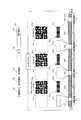
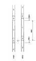
図39は図38(b)で説明したバーコードの具体的な表示方法を示す。まず図39(a)を用いて説明する。図38(b)のステップ668eで無表示状態の副表示部に第1のバーコード751aや752a(図39)をステップ668fでT1時間表示する。ステップ668gでnが最後でなければステップ668kで無表示757aを表示する。ステップ668mでT1より短い一定時間T2表示すると、ステップ668d,668eで2番目のバーコード751bや752bをT1時間(ステップ668f)表示し、無表示757bをT2時間(ステップ668m)表示する。最後のn番目のバーコード751を表示し終わると、ステップ668hでm回目のサイクル以内であれば、ステップ668nで無表示757zをT2より長いT3時間の無表示期間754表示し(ステップ668p)、再び第1のバーコード1をT1の期間755a表示する。これをm回繰り返す。
【0329】
バーコード751aもしくはバーコード752aのいずれかを単独で表示してもよい。また、バーコード751aとバーコード752aを図のように同時に表示してもよい。同時に同じ内容のデータをバーコード751aと752aの両方で表示すると、一次元のバーコードリーダでも二次元のバーコードリーダのいずれでも読めるという効果がある。この場合は、図39(a)のようにバーコード751aと752aはn個のパターンを表示させるが、二次元バーコードの場合は表示データ量が大きいためnより少ないK個のパターンを表示させる。但し、n>Kとする。このことにより、バーコード752の表示時間はT1のK/n倍の表示時間となるため、バーコードの認識がより確実になる。
【0330】
図39(b)に示すように、サイクルの最初だけ無表示757zを設け、残りはバーコード751a,751b,751cの間に無表示を設けなくすることにより、表示を速くすることもできる。
【0331】
ここで本発明では、無表示期間756a,756b,756cを設けたことにより、バーコードリーダーの誤認識を少なくすることができる。一般的にバーコードリーダーには、レーザースキャンや手走査や二次元センサといった走査型があり、主流である。もし、走査中にバーコードの表示が急に変わると、例えば前半分はバーコード1が読まれ、後半分はバーコード2が読まれ、全く違ったバーコードが読まれてしまうことになる。もちろんエラー訂正で多くは排除できるが、完全にエラーを除去することは難しい。またエラーによるリトライで読み取りに時間を要する。
【0332】
本発明のように、バーコード1の表示期間とバーコード2の表示期間の間に無表示期間756をT1>T2となるように設けることにより、バーコード1とバーコード2の間の時間的なクロストークによる読み取りエラーを大巾に減少させることができる。また、各サイクルの始めに無表示757zをT3(T3>T2)の間表示させる。すると読み込み時にバーコードリーダーが時間を測定することにより、先頭のバーコード1;751aを検出できるので読み取りデータの先頭データの同期検出が容易にできるという効果がある。この場合、無表示画面として黒画面と白画面が考えられる。白画面の方が信号がなくなるのでノイズの面から効果的である。
【0333】
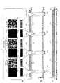
また、図40のように最初にスタートコードが含まれたバーコード751a、752aを入れることにより、先頭の同期検出ができるため、データ読み取りが速くかつ確実になるという効果がある。この場合は、図40に示すように各バーコード間の無表示期間T2は全て同じでもよい。
【0334】
また、バーコード751a、752aの先頭部やバーコード751a、752aの特定部もしくは変調データの先頭部に循環型表示時の表示の順序を示す表示順番号759と表示総数760を表示する。このことにより、バーコードリーダーの読み取り時に、先頭のバーコードではなく、たまたま部分的に2番目の表示である751bしか読み取れなかった場合でも、表示順番号759を関連づけてバーコードリーダーに情報を蓄積しておき、次々と表示順番号759をみて、表示総数760分を読み取るまで読み込むことができる。
【0335】
この方式によりランダムなバーコードの部分的な読み込みが可能となるため全データの読み込み時間が早くなるという効果がある。この場合の、各々のバーコード表示のデータ構造762は、図40に示すようになっている。すなわち同期表示761,表示順番号759,表示総数760,データ764,終了表示763の各データがこの順序で配列されている。
【0336】
さて、全数のバーコードの読み込みが完了すると通常のバーコードリーダー708(図26)は終了を知らせるブザー音を発生する。この終了音を図17に示すマイク594で入力させ検知回路で検知するとよみ取り終了がわかるので、一定時間後に終了状態を画面や点滅ランプで表示するとともにスピーカ573を用いて終了のブザー音を鳴らせて、使用者間746に音声と表示で通知する。そして、一定時間後循環型のバーコード表示の動作を終了する。
【0337】
図41(a)(b)(c)にバーコードの反射光量と検出信号を示す。図40で説明したように、無表示は白表示と黒表示の2種類あるが、図39の白表示に換えて黒表示の無表示758を表示した場合を、図41(a)に示す。図41(b)に示すように、バーコードの無表示時には信号はなくなる。従来行われているバーコード読み取り作業において手作業で複数のバーコードを読む場合、商品タグからバーコードリーダーを離すと反射光が戻ってこなくなるため、反射検出検出信号はなくなる。
【0338】
図41の表示方法であると、あたかもこの無表示期間765の間はバーコードリーダーを離した状態もしくは、バーコード表示がない状態と同様、信号レベルが低くなる。このため通常のバーコードリーダーは無表示期間765の後の信号を次の新たなバーコードと認識して読み取ることが容易となる。この方法により、本発明の複数のバーコードを循環的に表示しても問題なく読み取り、印刷バーコード読み取り用のバーコードリーダーでの読み取り時の互換性が高くなるという効果がある。
【0339】
この方法は、光検知部725を設けなくてもT1をバーコードリーダーに合わせ最適化することにより確実にバーコードが読み取れる。使用者はPOS端末で認定する直前にBCスイッチを押すと、バーコードの表示サイクルが数十回行なわれ、バーコードリーダーを表示部にあてるだけでデータが読み取られる。読み取りが終わるとPOS端末がブザー音等で完了を知らせてくれるので、使用者はBCスイッチを押しバーコードの連続表示を止めればよい。後はPOS端末に表示される代金を支払うことにより、商品やサービスがクーポン割引価格で購入できる。
【0340】
本発明の携帯電話を用いて購入する場合、例えば宝石のように高額の商品を買う時は、認証データをセンターに送った後その携帯電話の電話番号もしくはURLへ認証センターが電話やパケット通信を行い、その携帯電話に着信音で通知させたり新たに認証センターから送られた認証コードをバーコードで表示させる。このバーコードをバーコードリーダーで読み取り再び認証センターへ送り、再び認証することにより高いセキュリティの認証と決済を実現できる。
【0341】
この携帯電話の盗難に関しては、BCスイッチを押すとパスワードが要求され、パスワードが間違っているとバーコード表示サイクルに入らないようにする。この処理により携帯電話の盗難による誤認証を防げる。従って現在のクレジットカードシステムに比べると、はるかに高いセキュリティを実現できる。
【0342】
本発明と同じような効果をもつ認証方式は別の方式を用いて提案されているが、いずれもPOS端末に新しい装置を付加導入する必要がある。しかし本発明では世界中の多くの商店に現在設置されている一般型のバーコードリーダーで読みとれる。このため、従来の商店の装置等のインフラストラクチャーを全く変えずに実現できる。このため経済的な効果が高い。また使用者は商店においてBCモードスイッチを押すだけでよく、従来のような余分な操作や入力が要らないため認証や決済時の手順が簡略化するため省力化され、利便性が著しく向上する。
【0343】
本発明の液晶素子のバーコード読み取りを安定化するための液晶表示素子の特性面での最適化条件を述べる。本発明の表示部は、バーコードリーダーで読み取られるため、いくつかの素子に必要な条件がある。まず、ピッチ間隔:Lである。印刷の場合通常バーコードを印字するには、水平方向に100dpi以上の印字密度が必要である。これをピッチ間隔に換算すると250μmであるから、水平方向のピッチ間隔LはL>250μmとなる。本発明では、水平方向のピッチを250μm以下で作成することにより、読み取り可能なバーコード表示が実現できる。
【0344】
また、コントラスト比の最適条件を述べる。用紙印刷の場合OD値(Optical Density)値が定義されている。バーコード印字に必要な一般の印字用紙のOD値は、0.7〜1.6とされている。つまり、OD値>0.7が最適条件である。OD値は対数表記であるので、OD値をコントラスト比に換算するとコントラスト比=4つまり、本発明の液晶表示素子をバーコードリーダーで正確に読み取らせる場合、反射値でみた場合、コントラスト比が4以上に設定すればよい。以上から本発明の表示素子は、水平方向の画素ピッチL<250μm、反射時のコントラスト比CR>4の2つの条件の範囲に設定する。これにより、読み取り時に安定して読むことができる。
【0345】
反射膜のないバックライト方式の完全な透過型液晶素子の場合は、バーコード読み取りは困難である。しかし、本発明を部分的に反射膜を設けた、もしくは、半透過型の反射膜を設けた液晶表示素子に適用することにより、バーコードリーダーで読み取ることができる。この場合の条件は、反射光でみた場合、CR>4に設定することによりバーコードリーダーで安定して読むことができる。
【0346】
(6−10)電子マネーへの適用
また、上述した方法を携帯電話を用いた電子マネーに適用することもできる。以下、図33を用いて説明する。この場合、セキュリティを上げるため、バーコードとして表示するデータを時間情報とともに、スマートカード(例えば、SIMカード)803の中に入っている暗号鍵を用いて暗号化し、バーコードデータを生成して表示する。この暗号化されたバーコードをバーコードリーダー708で読み取り、POS端末750の中にある復号鍵で復号化する。この方法であると本人から不正に入手したバーコードを複製して表示して決済しようとしても、時間が経過しており時間情報が一致しないためセキュリティが保たれる。
【0347】
また暗号鍵は交換可能なSIM−ICの中にあるため、万が一暗号鍵の情報が漏れ、セキュリティが破られたとしても、SIMカード803を交換するだけでよいので、セキュリティが保たれる。また、バーコード表示用のデータを、SIMカード803の中の暗号化回路により暗号化して、表示回路部へ出力しバーコード表示することによりセキュリティが上げられる。
また、バーコード表示用のデータの一部または全体を、サーバー801の暗号鍵で暗号化した上でこのデータを携帯電話501で受信するようにしても良い。この場合、携帯電話501はこの暗号データを得てバーコード表示する。POS端末750で読み取り、サーバー801へ送る。サーバー801の復号鍵で復号し、認証することによりセキュリティをさらに上げることができる。
【0348】
電子マネーに適用した場合は、サーバー801から相互認証通信を行い、例えば100ドルの電子マネーの金額を、携帯電話501のメモリ802にダウンロードする。この電子マネーを使用する場合は、現実商店へ移動する。商品の購入金額が20ドルの場合、使用者がこの携帯のBCモードスイッチを押し、電子マネーモードのバーコード表示をさせる。この時に表示されるバーコードには、電子マネーのサービスIDとサービス会社IDと残高金額と、携帯電話IDもしくはユーザーIDとが含まれる。
【0349】
ここで図42に、本実施の形態による電子マネーのデータ構造及びバーコードで表示される電子マネーのデータ構造を示す。図42(a)に示すように、電子マネーのデータ構造は、電子マネーの種類を表すIDとしてサービスIDやサービス会社IDが用いられている。そして残高金額、携帯電話IDもしくはユーザーIDに加えて、セキュリティ用の認証IDとして、サーバによる署名データが付加される。
【0350】
これにより、サーバ801の公開鍵による署名データによって、電子マネーを示すデータの改ざんを防止することができる。
【0351】
この電子マネーデータが携帯端末の表示部に表示される際には、スマートカードの暗号鍵によって暗号化が施される。そして図42(b)に示すように、上記データに加えて時間情報が付加されてバーコードとして表示される。このバーコードで表示された電子マネーデータは、上述したようにPOS端末で復号化される。
【0352】
商店のPOS端末750に、携帯電話501の本発明のバーコードを読み取らせると、購入金額が小額の場合、POS端末750は、読み取ったバーコードデータを復号鍵で復号化し、残高金額が購入金額以上であれば決済し、残高金額から購入金額を差し引いた新しい残高金額をインターネットと携帯電話回線の下り回線経由で携帯電話501に送り、携帯電話501の残高金額データを書き替える。
【0353】
この下り回線のデータはブルートゥースや無線LAN等の通信方法を用いてPOS端末750から携帯電話501に直接送ってもよい。さらに上りデータもブルートゥース等を使ってもよい。この場合、通信認証用のトークン等のID情報や通信用の暗号鍵情報を携帯端末の表示部にバーコードで表示することによりトークンを用いた通信の相互認証用に用いることにより携帯端末と固定端末とがお互いに特定できるので、複数の端末が存在しても、バーコード認証できた1台の端末に通信が特定できる。従って、携帯端末と固定端末との間の通信の確実性と安全性と迅速性が向上する。また暗号通信により情報のセキュリティを上げることができる。
【0354】
金額が高額の場合は、上述の携帯電話501に回線経由で送ったデータに、認証データを加え、携帯電話501にバーコード表示させる。このデータをバーコードスキャナーで読み取りPOS端末750でこの認証データを検証し、認証した結果を確認して決済を完了させる。この方法により、一段とセキュリティを向上させることができる。
【0355】
電子マネーの決済処理において、POS端末750は、まず、バーコードが示すサービスIDから、電子マネー,商品購入クーポン,切符購入等のサービス種類を特定する。次に、バーコードが示すサービス会社ID(サービス会社のURL(Uniform Resource Locator)であっても良い)からサービス会社を特定し、必要に応じて通信回線やインターネットを介してサービス会社のURL等に接続する。
【0356】
POS端末750は、残高金額が購入金額以上である場合、バーコードが示す残高金額から購入金額を差し引いた新しい残高金額をセンターに送り、携帯電話の回線を経由して携帯電話501に新しい残高金額を送る。
【0357】
そして携帯電話501は、SIMカード803内のメモリの残高金額データを新しい残高金額データを書き替える。同時に残高金額データを画面に通常の文字とバーコードの双方で表示し、使用者に知らせる。同時にブザー音で使用者に残高金額の変更を通知する。このようにして、電子マネーの使用が行われる。
【0358】
この場合、POS端末750は、読み取ったバーコードデータを復号鍵で復号化し、署名データを検証して、さらに、残高金額が購入金額以上である場合、復号化したバーコードデータと残高金額から購入金額を差し引いた新しい残高金額とをサーバー801へ送る。サーバー801は、残高金額を更新し、さらに、署名データを更新して、これをインターネットと携帯電話回線の下り回線経由で携帯電話を送り、携帯電話501の電子マネーデータを書き替える。
【0359】
このシステムでは、既存のPOS端末750と携帯電話501のハードウェアを変えずに電子マネーシステムを構築できるので、投資が必要ないという効果がある。また、既存のバーコードリーダーやPOS端末750を使えるので、使用範囲が広く利便性が高い。
【0360】
また、この場合、使用者不在中に携帯電話501のバーコードのデータが読み取られて不正使用される可能性があるが、もし不正使用しても、不正が行われた時点で携帯電話に新しい残高金額が文字で表示され、さらに、ブザー音が鳴るため、不正使用を発見できる。
【0361】
また、1回目のバーコード表示時に携帯電話番号や携帯電話のメールアドレスを読み込ませた場合、上に述べた残額だけでなく認証データを携帯電話回線で送り、携帯電話にバーコード表示させる。これをバーコードリーダー708で読み取り認証をすることにより、他の携帯電話での不正使用を妨げる。
【0362】
また、個人のプライバシーの問題を避けるため、個人の携帯電話番号やURLは暗号化してバーコード表示させる。そして、通信回線でセンターに送りセンターで復号して、携帯電話番号やURLを得る構成にして、POS端末750では復号できないシステム構成にする。この構成により個人のプライバシーを守ることができる。
【0363】
(6−11)ローカル無線通信の適用
図43に、本発明をローカル無線通信に適用する場合の携帯電話501の構成を示す。図43では、図7との対応部分には同一符号を付して示し、その詳細な説明は省略する。この実施の形態では、サービス端末90が上述したPOS端末750であり、POS端末750から携帯電話501への下り回線データ及び上り回線データをブルートゥースにより伝送することにより、ローカル無線通信を実現する場合について説明する。
【0364】
下り回線データ及び上り回線データをブルートゥース等のローカル無線通信を使い、バーコード表示を個人認証用に用いると迅速性が向上する。この場合、サーバーと携帯電話501間のデータ通信はPOS端末750を介して行われる。この場合、POS端末750が複数存在する場合には、携帯電話105は特定のPOS端末750と通信セッションを確立する必要があるが、携帯電話105にローカル無線通信(例えば、ブルートゥース)における携帯電話のデバイスアドレスをバーコードで表示し、それを読み取ったPOS端末750との間で、選択的にローカル無線通信による通信セッションを確立するようにしても良い。
【0365】
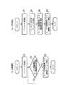
図44(a)、(b)は、それぞれ、バーコードによって選択的にローカル無線通信による通信セッションの確立を行う携帯電話とPOS端末750の処理のフロー図である。図44(a)において、携帯電話105は、まず、ステップ1faで、携帯電話105のデバイスアドレスを示すバーコードを表示する。次に、ステップ2faに進み、ローカル無線通信による接続要求の受信を待つ。ローカル無線通信による接続要求が受信された場合には、ステップ3faへ進み、接続を要求したデバイス(POS端末750)とローカル無線通信による通信セッションを確立する。
【0366】
一方、この時、POS端末750は、まず、ステップ1fbで、携帯電話105に表示されたバーコードを読み取り、ステップ2fbで読み取ったバーコードが示すデバイスアドレスが示すデバイスを検索する。次に、ステップ3fbで、検索したデバイス(携帯端末105)に対して、ローカル無線通信による接続要求を送信し、ステップ4fbで、そのデバイス(携帯電話105)とローカル無線通信による通信セッションを確立する。
【0367】
また、ステップ2faにおいて、偶然、他のデバイスから接続要求があり、間違って通信セッションが確立されてしまうのを防ぐため、携帯電話のデバイスアドレスと共に、乱数をセッションIDとしてバーコードで表示するようにしても良い。
【0368】
図45(a)、(b)は、それぞれ、この場合の携帯電話105とPOS端末750の処理のフロー図である。図45(a)において、携帯電話105は、まず、ステップ1gaで、セッションIDとして乱数Aを生成し、ステップ2gaで、携帯電話105のデバイスアドレスと乱数Aを示すバーコードを生成し、表示する。次に、ステップ3gaに進み、ローカル無線通信による接続要求の受信を待つ。ローカル無線通信による接続要求が受信された場合には、ステップ4gaへ進み、接続要求の中に含まれる乱数と乱数Aとを照合し、一致した場合にはステップ5gaへ進み、接続を要求したデバイス(POS端末750)とローカル無線通信による通信セッションを確立する。一致しなかった場合にはステップ3gaへ戻り、他のデバイスからのローカル無線通信による接続要求の受信を待つ。
【0369】
一方、この時、POS端末750は、まず、ステップ1gbで、携帯電話105に表示されたバーコードを読み取り、ステップ2gbで読み取ったバーコードが示すデバイスアドレスが示すデバイスを検索する。次に、ステップ3gbで、検索したデバイス(携帯端末105)に対して、ローカル無線通信による接続要求を送信し、ステップ4gbで、そのデバイス(携帯電話105)とローカル無線通信による通信セッションを確立する。この際、POS端末750は、ステップ3gbにおいて、読み取ったバーコードに含まれていた乱数をセッションIDとして接続要求の中に含めて送信する。
【0370】
このように、携帯電話105のデバイスアドレスと共に、乱数をセッションIDとしてバーコードで表示するようにすることにより、携帯電話105は、ローカル無線通信をしようとするPOS端末750と、確実に通信セッションを確立することが出来る。
【0371】
以上のようにして、POS端末750が複数存在する場合でも、携帯電話105は特定のPOS端末750と通信セッションを確立することができる。
【0372】
次にローカル無線通信でバーコードを自動表示する場合の携帯電話105の処理手順を、図46を用いて説明する。携帯電話はステップ1adでPOS端末750からクーポンの種類を表す識別情報を受信する。ここで携帯電話105がPOS端末750から受信するデータは、図47に示すように構成されている。すなわちクーポンのデータ構造は、サービスID及びサービス会社IDからなるクーポンの種類の識別情報と、クーポンの登録番号でなる個々のクーポンを示すIDと、商品IDと、割引後の価格からなる。
【0373】
携帯電話105はステップ2adにおいて、受信したクーポンの種類の識別情報に対応するクーポンを検索する。実際上、携帯電話105は、図43に示すCPU107が蓄積部108に格納されているクーポンの情報とステップ1adで受信したクーポン情報とを比較し、一致するものがあった場合にはステップ3adに移ってクーポンの情報を2次元バーコードで表示する。
【0374】
なお、本発明は、上述した実施の形態に限定されず、種々変更して実施することが可能である。
【0375】
【発明の効果】
以上の説明のように、本発明のOFDM信号伝送システムによれば、ユーザーが所望の放送局を選択してから、デジタル放送信号を受信し、その受信信号から伝送モードを判定する必要がないため、ユーザーの要求に即応して所望の情報を提供することが可能となる。また現在地が刻一刻変化するような移動受信環境においても、セル方式の移動無線通信における位置登録機能を用いることにより常に現在地を特定することができるので、現在地を特定するための情報の入力を、移動に応じて頻繁に行う必要がなくなる。
【0376】
また本発明の電子商取引システムによれば、携帯端末に、商品情報やサービス情報を受信する受信部を設けると共に受信した情報に基づいたバーコードを形成するバーコード形成部を設け、バーコード形成部により形成したバーコードを表示部に表示し、このバーコードを店舗端末等に設けられたバーコード読取装置で読み取ることで電子商取引を行うようにしたことにより、セキュリティの信頼性と決済の容易さを両立し得る簡易な構成の電子商取引システムを実現できる。
【図面の簡単な説明】
【図1】本発明の第1の実施の形態におけるデジタル放送受信装置の構成を示すブロック図
【図2】図1のOFDM復調部の内部構成例を示すブロック図
【図3】TMCC情報の内容を示す図
【図4】図1におけるCPUのプリセットモード及び視聴モードを示すフローチャート
【図5】図1における蓄積部の内容を示す図
【図6】本発明の第2の実施の形態におけるOFDM信号伝送システムの構成を示すブロック図
【図7】本発明の第3の実施の形態におけるOFDM伝送システムの構成を示すブロック図
【図8】本発明の第4の実施の形態におけるOFDM伝送システムの構成を示すブロック図
【図9】図8のCPUの動作を示すフローチャート
【図10】番組情報の内容を示す図
【図11】本発明の第5の実施の形態におけるΤモード携帯電話システムの全体構成図
【図12】Τモード携帯電話の移動と複数のサービスエリアの関係を示す図
【図13】第5の実施の形態における携帯基地局の構成を示すブロック図
【図14】待ち受けモード時及び通信コード時の受信データを示す図
【図15】送信情報と伝送情報の内容を示す図
【図16】通常の放送局、部分放送を行う放送局、及びデータ放送専用局の帯域図
【図17】Τモード携帯電話の構成を示すブロック図
【図18】伝送情報のパターンテーブルと頻度管理と時間管理テーブルを示す図
【図19】送信情報と第1、第2伝送情報を入手する手順のフローチャート
【図20】伝送情報をパターン情報化する手順のフローチャート
【図21】電界強度管理方式の伝送情報の入手する手順のフローチャート
【図22】頻度管理方法の伝送情報を入手する手順のフローチャート
【図23】送信情報と第1、第2伝送情報を入手する手順のフローチャート
【図24】送信情報と第1、第2伝送情報を入手する手順のフローチャート
【図25】伝送情報をパターン情報化する手順のフローチャート
【図26】本発明の第6の実施の形態における携帯電話と仮想商店と実在商店との認証手順を示す図
【図27】第6の実施の形態における携帯電話の各モードでの画面の状態を示す図
【図28】主表示部及び副表示部の表示ピッチ及び画素を示す図
【図29】図28の表示素子のA−A’面、及びB−B’面の断面図
【図30】バーコード読取装置の説明に供する図
【図31】光検知部と表示部の構成を示すブロック図
【図32】表示部の表示の手順を示すフローチャート
【図33】サーバーとクライアントと現実商店の構成を示す図
【図34】入場処理手順を示すフローチャート
【図35】携帯電話のメニュー画面、及びバーコードモード時の画面を示す図
【図36】携帯電話の画面表示のフローチャート
【図37】携帯電話の画面表示のフローチャート
【図38】携帯機器のバーコード表示の説明に供する図
【図39】所定間隔をもって各バーコードを表示する場合及びデータの先頭のみ間隔をもってバーコードを表示する場合のバーコード画面表示のタイミングチャート
【図40】バーコード画面表示のタイミングチャート
【図41】実施の形態でのバーコードからの反射光の検出の説明に供する図
【図42】電子マネーのデータ構造を示す図
【図43】ローカル通信でバーコードを自動表示する場合の携帯電話の構成を示すブロック図
【図44】バーコードによって選択的にローカル無線通信による通信セッションの確立を行う携帯電話及びPOS端末の処理手順を示すフローチャート
【図45】乱数をセッションIDとしてバーコードで表示してローカル無線通信による通信セッションの確立を行う携帯電話及びPOS端末の処理手順を示すフローチャート
【図46】ローカル通信でバーコードを自動表示する場合の携帯電話の処理手順を示すフローチャート
【図47】ローカル通信でバーコードを自動表示する場合のクーポンのデータ構造を示す図
【図48】従来のOFDM信号の構成を示す模式図
【図49】ガード期間の効果の説明に供する模式図
【図50】SFNの構成を示す模式図
【図51】地上デジタル放送方式における各モードの有効シンボル期間長に対するガード期間長の比率を示す図
【符号の説明】
10 デジタル放送受信装置
101 アンテナ
102 チューナ
103 OFDM復調部
104 情報源復号化部
105 出力部
106 入力部
107 CPU
108 蓄積部
109 制御バス
110 情報バス
501 テレビ受信型携帯電話(Τモード携帯電話)
502 地上波テレビ局
503 携帯基地局
504 放送信号
505 固定受信機
506 下り信号(携帯基地局からの送信信号)
507 上り信号(携帯電話からの送信信号)
510 携帯制御部
511 公衆網
512 サーバー
513 インターネット
514 固定アンテナ
515 固定電話局(有線電話用)
516 携帯基地局アンテナ
517 基地局送受信回路
518 通信制御部(RNC)
519 バックボーン
520 PDSL
521 基地局ID
522 携帯電話用データ
523 携帯電話用データ
524 テレビ受信用データ
525 テレビ受信用データ
526 送信情報
527 送信中のチャンネル
528 放送データ
529 部分セグメント
530 一般セグメント
531 携帯電話のアンテナ
532 1セグメント
533 部分伝送中のチャンネル
534 同一チャンネルの放送局の識別情報
535 チャンネルの電界強度情報
536 送信周波数
537 FFTサイズ
538 ガード比
539 送信電力
540 放送局のアンテナの送信電力
541 復調情報
550 部分放送識別子
551 変調方式
552 符号化率
553 時間インターリーブ長
554 第1パターン番号
555 第2パターン番号
556 伝送情報管理部
557 (伝送情報)データベースメモリ
558 位置検出部
559 伝送情報データベース
560 国検出部
561 共用器
562 フロントエンド
563 フィルタ
564 復調器
565 A/Dコンバータ
566 逆拡散部
567 同期部
568 検波部
569 データデコーダ
570 出力制御部
571 音声デコーダ
572 音声切換部
573 スピーカ
574 LPF
575 イヤホン端子
576 イヤホン
577 コード
578 テレビ受信部
579 切換部
579a 信号比較部
580 チューナ
581 周波数制御部
582 復調部
583 復調制御部
584 エラー訂正部
585 符号化制御部
586 出力部
587 映像デコーダ
588 信号レベル比較部
589 表示回路
590 表示部
591 副表示回路
592 副表示部
593 キーボード
594 マイク
595 音声デコーダ
596 チャンネルコーディック
597 1次変調器
598 拡散部
599 ROF
600 D/A
601 変調器
602 ミキサ
603 発振器
604 発振器
605 パワーアンプ
606 送信部
607 受信部
608 データ処理部
609 使用頻度管理テーブル
610 頻度情報
611 パワー制御情報
612 電界強度管理部
613 使用時間管理テーブル
614 最新パラメータ
615 次新パラメータ
616 次次新パラメータ
620 増巾部
622 送信部
623 受信部
700 画素素子
701 画素
702 境界線
703 バー(荒い)
704 バー(精細)
705 Rフィルタ
706 Gフィルタ
707 Bフィルタ
708 バーコードリーダー
709 発光部
710 光源
711 入射光
712 反射光
713 反射板
714 偏光板
715 ガラス基板
716 トランジスタ
717 電極
718 液晶
719 ITO
720 カラーフィルタ層
721 ガラス板
722 偏光板
723 透明層
724 カラー表示部
725 光検知部
726 カラーフィルタ
727 入射窓
728 光強度測定部
729 光入力時間測定部
730 分離部
731 連続信号検出部
732 パルス信号検出部
733 バーコード表示制御部
734 表示回路
735 タイマー
736 BCモードスイッチ
740 仮想商店
741 インターネット
742 携帯電話会社
743 通信制御部
744 サーバー
745 仮想商店群
746 使用者
747 登録番号メモリ
748 商店(現実の)
749 従業員
750 POS端末
751 バーコード
752 バーコード(二次元)
753 携帯テレビ受信機
754 無表示期間
755 表示期間
756 無表示期間
757 無表示
758 無表示(黒)
759 表示順番号
760 表示総数
761 同期表示
762 終了表示
763 データ構造
764 データ
765 無表示期間
801 サーバーシステム
802 メモリ
803 SIMカード(Subscriber Identi fication Module)
804 携帯電話番号
805 ユーザーID
806 割り当てID
807 Webページ
808 サーバエンジン
809 クライアントIDテーブル
815 在庫データベース
816 位置情報
817 近隣商店情報
818 時間情報
819 クーポンID
820 クーポン管理データベース
821 有効期限情報
822 メモリ(購入データベース)
823 商品金額
824 商品ID
825 クーポン割引率
826 ブラウザ
900 決済会社[0001]
BACKGROUND OF THE INVENTION
The present invention relates to an OFDM signal transmission system used for terrestrial digital broadcasting and electronic commerce using communication.
[0002]
[Prior art]
In recent years, digitalization of broadcasting has progressed globally regardless of transmission paths such as satellite, cable, and ground. Among these, the terrestrial digital broadcasting system in Europe and Japan adopts an orthogonal frequency division multiplexing (hereinafter referred to as OFDM (Orthogonal Frequency Division Multiplex)) transmission system.
[0003]
The OFDM transmission method modulates information by transmitting a plurality of carriers orthogonal to each other for each symbol period, and multiplexes and transmits these modulated waves. When the number of carriers used increases, The symbol period is extremely long, and it is difficult to be affected by multipath interference.
[0004]
In the OFDM transmission scheme, a redundant period called a guard period is provided for each symbol period to prevent the occurrence of intersymbol interference, thereby further enhancing the resistance to multipath interference. The reason why such a redundancy period can be provided is that the symbol period of the OFDM signal is extremely long, and the reduction of the transmission capacity due to the addition of the redundancy period can be accommodated.
[0005]
FIG. 48 is a schematic diagram showing the structure of an OFDM signal. Hereinafter, a period necessary for transmitting information is referred to as an effective symbol period, and the entire period obtained by adding a guard period to the effective symbol period is referred to as a symbol period. As indicated by hatching in the figure, the guard period of the OFDM signal is a cyclic copy of the signal of the last part (copying part) of the effective symbol period.
[0006]
Next, how the guard period increases the resistance to multipath interference will be described with reference to FIG. The desired wave and the delayed wave in the figure represent OFDM signals that arrived with a time difference of τ, G1 and G2 represent the guard periods of the first and second symbols, respectively, and S0, S1, and S2 represent the 0th. , Represents the effective symbol period of the first and second symbols. Here, in period A and period B in the figure, different symbols are received for the desired wave and the delayed wave, but in period C, the same signal is received. That is, as long as the time difference τ is shorter than the guard period length, the intersymbol interference due to the delayed wave is within the guard period, and does not adversely affect the effective symbol period of the desired wave.
[0007]
When the OFDM transmission method is adopted as a transmission method for digital terrestrial broadcasting, an SFN (Single Frequency Network) that constructs a relay network with a single frequency is realized by taking advantage of the high resistance to multipath interference. And effective use of frequency resources can be achieved.
[0008]
50A shows a case where a large-scale SFN is constructed using a high-power relay station, and FIG. 50B shows a case where a small-scale SFN is constructed using a low-power relay station. When comparing (a) and (b) of FIG. 50, the distance between the
[0009]
However, if the guard period is made longer, the redundant time will be increased accordingly. Even though the symbol period of the OFDM transmission method is long, the high definition television (hereinafter referred to as HDTV (High Definition TeleVision) with a large amount of information). ) When broadcasting video, a decrease in transmission capacity may be a problem.
[0010]
Therefore, in order to suppress the decrease in transmission capacity due to the guard period as much as possible when constructing a large-scale SFN, it is advantageous to increase the symbol period.
[0011]
On the other hand, the Japanese terrestrial digital broadcasting system adopts differential two-phase phase shift keying (hereinafter referred to as DQPSK) as a modulation method of each carrier, or temporally adjacent symbol data. By adopting temporally interleaved dispersion, stable reception is possible even in a mobile reception environment in which the transmission path characteristics fluctuate with time.
[0012]
In this case, the shorter symbol period is less affected by the time variation of the transmission path characteristics, and stable reception performance can be obtained even at high speed.
[0013]
As described above, when broadcasting an HDTV video in a large-scale SFN or broadcasting a service for a moving body that moves at high speed, the optimum symbol period length varies depending on the service content.
[0014]
In order to meet such a demand, in the Japanese terrestrial digital broadcasting system, as shown in FIG. 51, three types of modes having different effective symbol period lengths, and four types of guard period ratios (effective symbol periods) for each mode. The ratio of guard period length to length) is prepared. Hereinafter, a total of 12 types of combinations are referred to as transmission modes. Of these, for example, in the
[0015]
Once the broadcaster's relay station location is determined, the maximum time difference until the broadcast wave from each relay station arrives at the reception point in the service area can be estimated. Is determined. Since this numerical value is different for each relay network, there is a possibility that the guard period length and the effective symbol period length may differ depending on the region or broadcaster.
[0016]
In addition, when the guard period length determined by the relay station is, for example, the above-described 126 μsec, the broadcaster sets the guard period ratio to 1/8 in
[0017]
Furthermore, after the broadcast service is started, the distance between relay stations is shortened by increasing the number of relay stations, and if the above-mentioned time difference is reduced, the necessary guard period length is also shortened, but the guard period is originally a redundant period unnecessary for information transmission From the viewpoint of effective use of frequency resources, the guard period length is naturally changed to the minimum necessary length.
[0018]
As described above, the transmission mode represented by the combination of the effective symbol period length and the guard period ratio may vary depending on the region or the broadcaster, and may also change over time for a single broadcaster. is there.
[0019]
On the other hand, the demodulation process of the OFDM signal on the receiving side is performed by multiplex transmission by cutting out only the period necessary for demodulation from the received signal and applying fast Fourier transform (hereinafter referred to as FFT) to the signal. After the carriers are separated, detection processing is performed in accordance with the modulation scheme of each carrier, and transmission modes such as effective symbol period length and guard period ratio are essential information in the processing process.
[0020]
Therefore, a method for automatically acquiring the above-described transmission mode information by signal processing from the received signal itself when the transmission mode of the received signal is not known is disclosed in Japanese Patent Publication No. 2863747 or Japanese Patent Publication No. 2879034. Yes.
[0021]
The prior art disclosed in these documents is based on the fact that the guard period of the OFDM signal is a cyclic copy of the signal at the end of the effective symbol period. The effective symbol period length and the guard period length are determined by calculating the correlation with the signal delayed by the symbol period length and analyzing the waveform of the correlation signal.
[0022]
Conventionally, various electronic commerce transactions such as purchase of products using a communication network such as the Internet have been performed. In such electronic commerce, for example, a product to be traded is posted on a homepage. The user connects to the homepage via the Internet from his / her terminal, selects a product to be purchased, and inputs user information for identifying himself / herself.
[0023]
Then, a payment method such as input of a credit number, input of an ID during a payment period, or price exchange is designated. The operation organization (center) of the home page places an order for the product upon completion of such input, and the trader who has received the order delivers the product to the user and receives payment of the fee by the designated settlement method.
[0026]
[Problems to be solved by the invention]
In electronic commerce using the above-described communication network, security and settlement are troublesome. In terms of security, for example, when a credit card is used, there is anxiety such as counterfeiting. In terms of settlement, the reliability of security is reduced when settlement is made with simple work. In order to realize security and ease of settlement, there is a problem that the system configuration becomes large.
[0027]
Therefore, the present invention solves the above-mentioned problem, provides desired information in response to the user's request, and even when the broadcaster switches the transmission mode depending on the service content of the program, without interruption. It is an object of the present invention to provide an OFDM signal transmission system that can provide information to the network.
[0028]
Another object of the present invention is to provide an electronic commerce system having a simple configuration that can achieve both security reliability and ease of settlement.
[0033]
[Means for Solving the Problems]
The portable terminal of the present invention includes a receiving means, a barcode forming means, a display means,Detection means for detecting light or signal from bar code readerAnd the barcode forming means converts the data received by the receiving means.pluralConverted into a bar code, the display means,pluralBarcodeSequentiallydisplayAt the same time, the barcode reader displays information that allows the barcode reader to identify the order or total number of the plurality of barcodes, and the barcode reader is currently displayed from the detection result of the detection means. Determines whether the reading of the current barcode has been completed, and switches the barcode display when determining that the reading has been completed.Mobile device.
[0034]
With this configuration, a bar code corresponding to the received signal can be displayed, so that, for example, when used for electronic commerce, settlement can be easily performed. In addition, since the mobile terminal generates a barcode, the size of data that needs to be received can be smaller than when the barcode itself is received.
Also, with this configuration, when the amount of data to be displayed with a bar code is large, a large amount of data can be displayed with a plurality of bar codes without increasing the bar density. As a result, large-capacity display bar code data can be read without erroneous recognition.
In addition, with this configuration, if the bar code display is switched in conjunction with the detection result of the detection means, it is automatically linked appropriately to the reading operation of the bar code reader without the operation of the mobile terminal user. The bar code display will be switched.
Also, with this configuration, when the barcode is read by the barcode reader, the information read by the barcode reader in association with the display sequence number even when only the second barcode is read instead of the top barcode, for example. Can be read until the display total number is read. As a result, random barcodes can be partially read, and the time for reading all data can be shortened.
[0038]
The portable terminal of the present invention employs a configuration in which the barcode forming unit forms a one-dimensional barcode and a two-dimensional barcode from the data received by the receiving unit..
[0039]
The portable terminal of the present invention isThe display means includesMain display andHigher resolution than the main displayWith a secondary displayThe main display unit displays the two-dimensional barcode,Sub displayAdopts a configuration for displaying the one-dimensional barcode..
[0040]
With this configuration, a bar code corresponding to the received signal can be displayed, so that, for example, when used for electronic commerce, settlement can be easily performed. Further, since the sub display unit is provided and the barcode is displayed on the sub display unit, a desired image can be displayed on the main display unit even while the barcode is displayed, which is convenient.
In addition, with this configuration, since a detailed bar can be displayed, a reduction in the amount of information due to the barcode can be suppressed even if the display area is small.
Also, with this configuration, the amount of display data based on the two-dimensional barcode is larger than the amount of display data based on the one-dimensional barcode. When a large amount of data that takes a long time to display is requested to be displayed as a bar code, a two-dimensional bar code is selectively displayed on the main display unit so that a large amount of data can be displayed in a short time. Bar code can be displayed.
[0043]
In the portable terminal of the present invention, the main display unit is a color filter layer.IncludingSub-display part is color filter layerNot includingTake the configuration.
[0044]
With this configuration, when the sub-display unit is irradiated with light for barcode reading, the reflected light that has passed through any pixel receives only the same attenuation, so that even a high-density bar is not erroneously recognized.
[0045]
The portable terminal of the present invention isThe barcode forming means converts the data received by the receiving means into a plurality of barcodes, and the display meansBarcodeSequentiallyUse a configuration to display.
[0046]
With this configuration, when the amount of data to be displayed with a bar code is large, a large amount of data can be displayed with a plurality of bar codes without increasing the bar density. As a result, large-capacity display bar code data can be read without erroneous recognition.
[0051]
The portable terminal of the present invention isThe display means selects a display switching timing when sequentially displaying the plurality of barcodes according to the size of the data.Take the configuration.
[0052]
With this configuration, for example, when the amount of data to be displayed is large, the update timing of the two-dimensional barcode is accelerated, and when the amount of data to be displayed is not so large, the update timing of the two-dimensional barcode is delayed or not updated. By performing processing such as updating only the one-dimensional barcode, barcode display according to the data amount can be performed.
[0053]
The portable terminal of the present invention isThe barcode forming means converts the data into a plurality of one-dimensional barcodes and a plurality of two-dimensional barcodes, and the display meansDisplay on sub displaySaid saidOne-dimensional barcode andSaidDisplay on main displaySaid saidDisplay information amount per unit time of 2D barcode is the same, Display switching timing of the plurality of one-dimensional barcodes and the plurality of two-dimensional barcodesDisplay ofSwitching timing andUse a configuration to select.
[0054]
With this configuration, both the one-dimensional barcode and the two-dimensional barcode can display the same capacity per unit time. Therefore, even if the barcode reader uses a one-dimensional sensor, the barcode reader uses a two-dimensional sensor. It can also be read by a code reader. As a result, any type of barcode reader can be read, so that versatility can be improved.
[0055]
The portable terminal of the present invention isWhen the barcode forming means forms a plurality of bar coats, the display meansBetween each bar code display period with a non-display period of a predetermined periodSaidA configuration for displaying a plurality of barcodes is adopted.
[0056]
With this configuration, erroneous recognition of the barcode reader can be suppressed.
[0057]
The portable terminal of the present invention adopts a configuration in which the barcode display period is selected to be longer than the non-display period.
[0058]
With this configuration, reading errors due to temporal crosstalk between the preceding bar code and the next bar code displayed in succession are greatly reduced.
[0059]
The portable terminal of the present invention isWhen the data includes at least first data and second data, the barcode forming means converts the first data into a first barcode group consisting of a plurality of barcodes, and the second data The data is converted into a second barcode group composed of a plurality of barcodes, and the display means sequentially displays the first barcode group and the second barcode group, and the first barcode Group and the second barcode groupAmongSaidThe non-display periodThe first or second bar code groupInsideSaidThe configuration is made longer than the non-display period.
[0060]
With this configuration, if the bar code reader measures the time of the non-display period when reading a bar code, the bar code at the head of each information can be detected, so that the head data of the read data can be easily detected synchronously. It becomes like this.
[0063]
The portable terminal of the present invention is a bar code display switch.FurtherAnd the bar code display switchWhen turned onA configuration is adopted in which an input of a preset password is requested and a bar code is not displayed when a correct password is not input.
[0064]
With this configuration, a third party other than the user of the mobile terminal does not know the password. For example, erroneous authentication due to theft of the mobile terminal when the barcode display by the mobile terminal is used for authentication of electronic commerce is prevented in advance. it can.
[0065]
The portable terminal of the present invention further includes an encryption processing unit, and the encryption processing unit encrypts the data received by the reception unit,The barcode forming meansThe cryptographic processing meansThe output of toTake the configuration.
[0066]
With this configuration, for example, even if a third party illegally reads a barcode against the will of the user of the mobile terminal, the barcode information cannot be decrypted without the encryption key, and thus security can be improved. .
[0067]
The portable terminal of the present invention uses local wireless communication means.furtherEquipped,The barcode forming means includes:From the data received by the receiving means,SaidThe data indicated by the identification information received by the local wireless communication means is searched, and the searched data is barcoded.Convert toTake the configuration.
[0068]
With this configuration, an appropriate bar code can be displayed without a selection operation by the user of the mobile terminal, so that, for example, when used for electronic commerce, settlement can be easily performed.
[0112]
DETAILED DESCRIPTION OF THE INVENTION
Hereinafter, embodiments of the present invention will be described with reference to the drawings.
[0113]
Note that clocks, control signals, and the like necessary for the operation of each block in the block diagram are omitted in order to avoid making the drawing complicated except those necessary for explaining the operation of the present invention. ing.
[0114]
(1) First embodiment
FIG. 1 is a block diagram showing a configuration of a digital
[0115]
In this embodiment, although the transmission mode varies depending on the region or the broadcaster, etc., the transmission mode does not change in a short time, such as a program unit, and is assumed to be used mainly in a fixed reception environment such as home. To do.
[0116]
In FIG. 1, an
[0117]
In general, the transmission information sequence is in the form of a transport stream (hereinafter referred to as TS (Transport Stream)) of MPEG2 (Moving Picture Experts Group 2), and includes a high-efficiency encoding (compression). The recorded video information, audio information, data, and the like are multiplexed.
[0118]
The information
[0119]
The
[0120]
Here, the
[0121]
FIG. 2 is an internal configuration example of the
[0122]
The
[0123]
The
[0124]
The demodulation
[0125]
The control bus I /
[0126]
Actually, the transmission mode information may be used to generate a control signal necessary for the operation even in the block such as the
[0127]
Here, in the Japanese terrestrial digital broadcasting system, demodulation information is transmitted using a signal called TMCC (Transmission and Modulation Configuration Control), and the contents thereof are shown in FIG.
[0128]
Next, the operation of the digital broadcast receiving apparatus in this embodiment will be described with reference to the drawings. The digital broadcast receiving apparatus includes at least a preset mode and a viewing mode as its operation state.
[0129]
FIG. 4 is a flowchart showing the operation of the
[0130]
In the preset mode, first, information for specifying the current location is acquired from the input unit 106 (step S1). Next, the start address A and the number of information n of the channel selection information corresponding to the specified current location are acquired (step S2), and the address A of the channel selection information is transferred from the
[0131]
Here, as the information for specifying the current location, an address, a postal code, a telephone number, etc. are used, and the
[0132]
In the viewing mode, first, the input of the button j assigned with the channel selection information address in the preset mode is acquired from the input unit 106 (step S11). Next, the address A + j assigned to the button j is accessed (step S12), and the channel selection information of the address A + j is acquired from the storage unit 108 (step S13). Then, the frequency information Fj is transmitted to the tuner 102 (step S14), and the transmission mode information Mj is transmitted to the OFDM demodulator 103 (step S15).
[0133]
FIG. 5 shows an example of the contents of the
[0134]
With the above configuration, according to the configuration of the present embodiment, it is not necessary for the user to select a desired broadcast station, receive a digital broadcast signal, and determine the transmission mode from the received signal. It is possible to provide desired information in response to a request.
[0135]
Although the method for accumulating channel selection information in the accumulating
[0136]
In addition, as a method of obtaining new channel selection information, a method of multiplexing channel selection information in a transmission information sequence in a digital broadcast signal, a method of obtaining additional communication means via a communication line, or via a recording medium You can use the method to obtain.
[0137]
(2) Second embodiment
FIG. 6 is a block diagram showing a configuration of an OFDM signal transmission system according to the second embodiment of the present invention. In FIG. 6, components having the same reference numerals as those in FIG. 1 perform the same operations as those in the first embodiment.
[0138]
In this embodiment, the transmission mode differs depending on the region or broadcaster, but when the transmission mode does not change in a short time such as a program unit, it is mainly used in mobile reception environments such as automobiles and mobile phones. Assumed.
[0139]
In addition, the present embodiment performs the same operation as the first embodiment except that the current location is specified using a global positioning system (hereinafter referred to as GPS (Global Positioning System)).
[0140]
In FIG. 6, the
[0141]
With the above configuration, according to the configuration of the present embodiment, it is not necessary for the user to select a desired broadcast station, receive a digital broadcast signal, and determine the transmission mode from the received signal. In addition to being able to provide the desired information immediately upon request, even in a mobile reception environment where the current location changes every moment, the current location can be identified by using GPS. It is not necessary to frequently input information for specifying the number according to movement.
[0142]
(3) Third embodiment
FIG. 7 is a block diagram showing a configuration of an OFDM signal transmission system according to the third embodiment of the present invention. In FIG. 7, the constituent elements having the same reference numerals as those in FIG. 1 perform the same operations as those in the first embodiment.
[0143]
As in the second embodiment, this embodiment differs in transmission mode depending on the region or broadcaster, etc., but in the case where the transmission mode does not change in a short time such as a program unit, It is assumed to be used in mobile reception environments such as mobile phones.
[0144]
In addition, this embodiment performs the same operation as that of the first embodiment except that the current location is specified using the location registration function in the mobile communication system using the cell system.
[0145]
A cell-based mobile radio communication system is a system that divides a service area into small areas called cells and installs a base station in each area, and performs tracking connection according to user movement. In this system, since the user moves across a plurality of cells, it is necessary to always know in which cell the mobile device exists. In addition, a location registration function is provided as an indispensable control technique for continuing communication smoothly even if the cell changes.
[0146]
In the location registration, the mobile device acquires location information from the base station, registers the information in its own device, and notifies the network. After that, when a position change is detected, the mobile device updates the location registration within itself and notifies the network as well. In addition, if the mobile device is turned off and then turned on again, the location information from the base station at that time is compared with the location information in its own device. Notify the network of location information.
[0147]
In FIG. 7, the
[0148]
With the above configuration, according to the configuration of the present embodiment, it is not necessary for the user to select a desired broadcast station, receive a digital broadcast signal, and determine the transmission mode from the received signal. In addition to being able to provide desired information immediately upon request, even in mobile reception environments where the current location changes from moment to moment, it is always possible to use the location registration function in cellular mobile radio communications. Therefore, it is not necessary to frequently input information for specifying the current location according to movement.
[0149]
(4) Fourth embodiment
FIG. 8 is a block diagram showing a configuration of an OFDM signal transmission system according to the fourth embodiment of the present invention. In FIG. 8, the constituent elements having the same reference numerals as those in FIGS. 1 and 7 perform the same operations as those in the first embodiment and the third embodiment.
[0150]
This embodiment is mainly used in mobile reception environments such as automobiles and mobile phones when the transmission mode varies depending on the region or broadcaster and the transmission mode changes in a short time such as a program unit. Assumed.
[0151]
In the present embodiment, program information including transmission mode information is transmitted using a line different from broadcasting, and the information is used at the time of channel selection.
[0152]
In FIG. 8, a program
[0153]
On the other hand, unlike the first to third embodiments, the digital
[0154]
FIG. 9 is a flowchart showing the operation of the
[0155]
First, a menu is presented to the user through the output unit 105 (step S20). When the user desires digital broadcasting (steps S21 and S23), a program information distribution request to the program
[0156]
When the program
[0157]
The
[0158]
When the user selects a desired program from the list (step S26), channel selection information corresponding to the program is acquired from the storage unit 108 (step S27), and the frequency information is transmitted to the tuner 102 ( In step S28), transmission mode information is transmitted to the OFDM demodulator 103 (step S29).
[0159]
FIG. 10 shows an example of the contents of the program information. In this example, the program information includes a title and a genre as content information, frequency information and transmission mode information as channel selection information, and a start time and an end time as time information for each program.
[0160]
With the above configuration, according to the configuration of the present embodiment, it is possible to provide a program desired by a user without performing a preset operation, and in addition, a mobile reception environment in which the current location changes every moment. However, since the current location can always be specified by using the location registration function in the cellular mobile radio communication, it is not necessary to frequently input information for specifying the current location according to the movement.
[0161]
If the program information is distributed including the schedule up to a certain extent, such as within 24 hours or one week from the current program, and the digital
[0162]
In this embodiment, the channel information is associated with the program as the program information. However, although the transmission mode differs depending on the region or the broadcaster, the transmission mode can be changed in a short time as a program unit. Assuming that there is no change, the program
[0163]
Further, after the assignment, when the transmission mode changes or the current location changes due to movement, the digital
[0164]
(5) Fifth embodiment
In the fifth embodiment, transmission information management performed by a transmission information management unit configured by a CPU will be described. Details of frequency management of transmission information, time management such as elapsed time after use, field strength management, management and prediction of channel area identification service contents, information compression by patterned information, and the like will be described in detail. The transmission information is included in either or both of transmission data from the base station of the form phone and / or transmission data from the television broadcasting station. In the embodiment, the transmission information will be described using an example of transmission from the mobile phone base station.
[0165]
(5-1) Overall configuration
FIG. 11 is an overall view showing the relationship among the television receiving
[0166]
(Mobile reception) On the other hand, the television receiving
[0167]
(Fixed-station reception) As described above, when receiving also with a
[0168]
There is a large difference in reception conditions between the case where the above-mentioned digital television broadcast is received by the
[0169]
However, when receiving a broadcast of a channel other than SFN, the electric field strength is reduced at a certain point between
[0170]
Therefore, a user of a television receiving type mobile phone switches the frequency with a tuner and tries to find a broadcast channel. Finally, it knows the presence of the
[0171]
There are tens to thousands of combinations of parameters. For this reason, parameter matching takes time. After obtaining the demodulated information of the first layer of the received signal, the information can be obtained because the second and higher layers can be demodulated. In this way, time is required for parameter determination. When a frequency is included, a television reception signal cannot be output for several seconds to a maximum of tens of seconds during this period. If the received channel is not broadcasting the service desired by the user, the channel is switched to another channel to search for the channel of the desired service. In this case as well, it takes time to determine the parameters in the same manner, so that extra time is required.
[0172]
In the present invention, at least the base station ID is received from the
[0173]
Here, FIG. 13 shows the configuration of the
[0174]
The
[0175]
Further, the
[0176]
(5-2) Description of first and second transmission information
The
[0177]
FIG. 14A shows transmission data when the mobile phone is in a standby mode. The
[0178]
The
[0179]
As an example, the case of ISDB-T standard is shown. As shown in FIG. 16 (a), in one broadcast band of 6 MHz or 8 MHz,
[0180]
However, in the embodiment, as shown in FIG. 16B, one or two specific partial segments 529 out of the 13 segments are more resistant than the other
[0181]
This hierarchical broadcasting is called “partial transmission” or “partial broadcasting” in the present embodiment. Since the partial segment 529 is broadcast with a highly resistant parameter, it can be received even with a small antenna such as the antenna 531 (FIG. 17) of the mobile phone. On the other hand, in the case of partial broadcasting, since the use frequency band is narrow and the transmission efficiency is lowered, the transmission data capacity is greatly reduced from several hundred Mbps to about 1 Mbps.
[0182]
However, in the case of a mobile device such as a cellular phone, the display screen is small from 1 inch to several inches, and by adopting MPEG4 or wavelet method with good compression efficiency at a low transmission rate such as several tens Kbps to several hundred Kbps. It is possible to provide a screen with an image quality that does not hinder viewing.
[0183]
Further, as shown in FIG. 16C, data broadcasting using a
[0184]
Returning to FIG. 14, the
[0185]
It is necessary to identify both of them because they move when receiving a television from a mobile phone. Therefore,
[0186]
In this way, by adding identifiers that can identify different broadcast stations by region with the same frequency and defining the channels of each broadcast station, broadcast stations in different regions that use the same frequency band, that is, the channel, can be identified from each other. For this reason, it is possible to prevent malfunction due to erroneous transmission parameter settings due to misidentification of broadcasting stations of the same channel.
[0187]
Further, the base station corresponding to the present invention transmits the
[0188]
Next, transmission information necessary for demodulation will be described in detail with reference to FIGS. As shown in FIG. 15 or FIG. 14, the
[0189]
As shown in FIG. 15, various parameters can be known by the
[0190]
In the case of mobile reception such as for mobile phones and automobiles, the parameters of the
[0191]
Since the first layer data includes
[0192]
However, as described above, transmission information parameters frequently change in mobile applications. If the second
[0193]
The effect will be described first. Transmission information is transmitted from the base station in the standby mode. For this reason, this information can be received even by a portable terminal such as a PDS that does not have an uplink, that is, a PDS that does not have a transmission function, and the reception time at the time of initial reception or channel change is large. There is an effect that the width is shortened.
[0194]
Even in devices with a transmission function such as mobile phones, transmission of mobile phones is prohibited in trains and hospitals in Japan and other countries, but in such places, switch to "Τ mode" with a switch. If this is done, transmission information can be received and obtained without transmission, which increases the use of mobile phone broadcast reception.
[0195]
Also, if you turn on the Τ mode switch before entering the mobile phone use prohibited area, the broadcast of the broadcast station that receives your area, use time zone, mobile terminal ID and call data to the base station or the broadcast station via the base station The station ID is transmitted. Then, when you receive a call on your mobile phone, your mobile device ID will be sent in the broadcast signal via the broadcast station. Since the notification is made, there is also an effect of paging that the reception notification is made almost without transmission of the mobile phone.
[0196]
In the saddle mode including the calling method of the present invention, since strong transmission radio waves are not transmitted, the transmission of mobile phone transmission radio waves has the effect of reducing the influence on the human body.
[0197]
A method for patternizing and managing transmission information parameters and compressing information will be described. Returning to the second transmission information in FIG. 14A, the
[0198]
There are 12 parameters for the first transmission information, and if the
[0199]
Therefore, as shown in the block diagram of FIG. 17 and the database list of FIG. 18, the transmission
[0200]
In this way, each broadcast station can express 16 × 16 = 8 bits, that is, all parameters of transmission information with 1-byte data. Therefore, if the pattern falls within this range, transmission information for 1000 stations in a specific country can be obtained. 1 KB of memory capacity may be consumed for recording. For this reason, there is an effect that consumption of the memory capacity can be reduced in a mobile phone having a small memory capacity.
[0201]
The frequency calculation and frequency management are performed by the transmission
[0202]
In the case of the W-CDMA (Wideband Code Division Multiple Access) system, which is the mainstream of next-generation mobile phones, calls can be made using the same mobile phone in Asia such as Japan and Western countries. As shown in FIG. 17, the saddle mode
[0203]
(5-3) Explanation of mobile phone
Demodulation of a downlink signal including transmission information by the mobile phone will be described using the block diagram of the saddle mode
[0204]
Next, the signal is output to the
[0205]
The received broadcast signal is switched between the signal received by
[0206]
The demodulated signal is restored by the
[0207]
The operation at the time of transmission of the cellular phone in FIG. 17 will be described. The user's voice is converted into an electric signal from the
[0208]
The codec output signal is modulated to QPSK or the like by the
[0209]
In this way, the base station ID transmitted from the mobile
[0210]
Note that the
[0211]
In addition, although the example which transmits the
[0212]
In this case, when the
[0213]
When switching to another channel while receiving a program of a broadcast station of a specific channel, the reception information of the channel of this other station is taken out from the
[0214]
For this reason, compared with the case where the parameter is not known, there is an effect that the time for switching to another channel can be greatly shortened. In this case, mobile reception becomes more reliable by transmitting not only transmission information of broadcasting stations in the current broadcasting service area but also transmission information of broadcasting stations in adjacent service areas.
[0215]
In this case, a base station ID having a base station service area corresponding to the broadcast service area of the broadcast station with a specific broadcast station ID is sent in correspondence. The receiver records this data in a transmission information database (DB) 559. After that, if the reception is interrupted and the base station ID is known even if the user moves, the transmission information can be determined and demodulated.
[0216]
However, at the first reception after a large movement, the reception parameters for the area are not known at all. Thus, when the reception of the television broadcast is interrupted and moved, the transmission information of the mobile phone base station is required.
[0217]
Here, three methods for demodulation are described. First, the first method will be described. The first method is a method of changing a parameter to a round-robin equation assuming that the
[0218]
The second method is a method of adding the receiving
[0219]
Since the second method just described has nothing to do with the mobile base station, there is an effect that no communication infrastructure other than broadcasting is required. The second method uses a mobile base station, but only uses a base station ID, so that there is an effect that it is not necessary to change existing mobile base station equipment. Even if the transmission information transmission method of the present invention is adopted, the number of mobile base stations is more than tens of thousands around the world, and it is expected that the response will gradually progress. In the process of the correspondence, there are many base stations that do not correspond, and the second method described above is effective and practical in that region.
[0220]
In order to switch between the above-mentioned second method and the third method, which is a fully compatible method for receiving transmission information from the base station, with the configuration of FIG. 17, the base station
[0221]
In this case, the same effect can be obtained by connecting to a specific Web site or the like on the uplink of the mobile phone, requesting transmission of transmission information in the area, and downloading the transmission information on the downlink.
[0222]
(5-4) Explanation of mobile base station
Next, the configuration and operation on the
[0223]
Next, a configuration to which a function for transmitting transmission information necessary for broadcast reception of a television or the like of the present invention is added will be described. A
[0224]
By continuously performing this demodulation for each channel, it is possible to obtain transmission information of optimum parameters necessary for tuning and demodulation. Some or all of these parameters are extracted by the broadcast reception
[0225]
Next, the operation of the transmission
[0226]
The
[0227]
As described above, by providing the television
[0228]
(5-5) Transmission information management system
There are a plurality of operation modes of the transmission information management system, and each mode will be described with reference to the drawings.
[0229]
(5-5-1) Parameter setting
First, the first method will be described with reference to the flowchart of FIG. First, in
[0230]
Returning to step 650d, if Yes, the process proceeds to step 650e, where the
[0231]
If the flag is “1” or “2” in
[0232]
Returning to step 651h, if the result is "No", the process proceeds to step 651m, and if a reception command for a specific channel is received from the user or the like, the mobile phone is set in the uplink transmission prohibited mode, manner mode, Check if “Τ mode” (broadcast reception only mode) is selected. If “No”, the process proceeds to step 651p, and if a command for obtaining transmission data by telephone is received from the user or the transmission information management unit 556 (FIG. 17), that is, if “Yes”, the process proceeds to step 651q. In
[0233]
Returning to step 651n, if the result is “No”, that is, in the uplink transmission prohibited mode, the process proceeds to step 651t, tuned to the frequency of the specific channel, and the
[0234]
In
[0235]
(5-5-2) Switching broadcast channels
With reference to FIG. 21, a method of switching broadcast channels accompanying the movement of a mobile phone will be described.
[0236]
Since the base station changes as the mobile phone moves, the base station ID changes in
[0237]
In the second term of
[0238]
In the
[0239]
Now, in
[0240]
In
[0241]
(5-5-3) Seamless channel switching
In FIG. 22, a method for acquiring transmission information of a new broadcast station via a broadcast reception signal, or switching between two lines via a mobile line from a server or a base station will be described using a specific flowchart. In step 653a, the first and second transmission information of the new broadcast station is obtained not only from the base station but also from the broadcast reception signal. First, it is checked in
[0242]
Returning to step 653c (FIG. 22), if the result is No, in
[0243]
If the result is No in
[0244]
Even if the base station in the area receiving by the above procedure is not compatible with the present invention and can only receive the base station ID, each of the broadcast reception signals of each station corresponding to the base station ID of the other station Since the transmission information, the first transmission information, the second transmission information, and the service ID are included, there is an effect of seamlessly switching to the new broadcasting station. In addition, even if there is no such service, since it can be obtained from the server via a mobile line, transmission information can be obtained in any case, and seamless channel switching is possible.
[0245]
(5-5-4) When the base station notifies the broadcast channel number being serviced
In FIG. 23, the procedure and effect by assigning area identification ID to different broadcasting stations on the same channel of each broadcasting station will be described. In step 654a, the base station transmits the channel number of the broadcast station and the broadcast station area identification ID or the broadcast station unique ID. In
[0246]
(5-5-5) Update frequency management table
FIG. 24 describes a frequency management and frequency information update method for frequency management data when a frequency management table 609 (FIG. 18) is provided for each channel ID.
[0247]
In
[0248]
Returning to step 655a, if the result is Yes, proceeding to step 655b, setting n = 0, adding 1 to n in
[0249]
Here, the process returns to step 655e. If the result is No, the process returns to step 655m. If n does not exceed the last value, the process returns to step 655d. If it exceeds, the first layer is demodulated in step 655n to demodulate the first layer. The second transmission information is obtained, and the second layer is demodulated. If it is received in
[0250]
In FIG. 25, the broadcast station ID is associated with the base station ID and registered in the transmission information management database in step 657i in the same manner as described above. Then, in
[0251]
(6) Sixth embodiment
An embodiment of a new business model performed using the
[0252]
(6-1) Mobile phone
First, a mobile phone used in this embodiment will be described. FIG. 27 is a front view of a
[0253]
FIG. 28 shows the arrangement of the image 701 of the display element of the present invention when the
[0254]
In particular, as shown in FIG. 30, since the
[0255]
In the present invention, the
[0256]
FIGS. 29A and 29B are cross-sectional views (a) and (b), respectively, showing the structure of the present invention in the cross sections taken along the lines A-A ′ and B-B ′ of FIG. 28. First, the
[0257]
A
[0258]
At this time, incident light of white light is absorbed by the
[0259]
In the present invention, the
[0260]
In this case, as shown in FIG. 28, an
[0261]
In order to use the display element of the present invention in an electronic payment system or the like, it is necessary to display 3 to 4 barcodes. If the bar code is manually displayed 3 to 4 times, it takes time and processing time.
[0262]
In order to improve this, in the display device of the present invention, as shown in FIG. 27, a
[0263]
This procedure will be described with reference to the flowchart of FIG. In
[0264]
Returning to step 661f, if the result is No, it is checked in step 661g whether there has been irradiation of the scanning bar code reader. When a specific pulse quantity I2 or more and a short pulse signal of t1> t2 or less is detected for a predetermined number of times n1 or more, if a predetermined time t3 (t2 <t3) has elapsed in
[0265]
(6-2) Explanation of overall business model
FIG. 26 shows a business flow diagram of a business model of authentication purchase, merchandise receipt, and settlement using the Τ mode
[0266]
A user configures a Web site on a server using product purchase software, and opens a homepage for product purchase. In step 660b, the user selects the
[0267]
In step 660c, product information and standard price information are transmitted from the
[0268]
In
[0269]
In step 660g, the
[0270]
When the processing of the system is finished, in step 660i, the
[0271]
In
[0272]
In response to the reading light, the
[0273]
In
[0274]
(6-3) Detailed system
FIG. 26 will be described in detail with reference to FIG. A purchase order is placed from the
[0275]
This allocation ID is associated with the purchaser information recorded in the
[0276]
These information and the
[0277]
At the same time, the server looks at the inventory database 815 of the
[0278]
Upon receiving a purchase request for a specific product, the
[0279]
When the consumer goes to the
[0280]
In this system, since a check can be made without going through a communication circuit at the time of purchase, authentication can be performed instantly and processing can be performed quickly. It is effective for payment at convenience stores that can be queued up and for ticketing at the entrance of the theater. If the payment procedure is completed with a mobile phone in advance, it does not take any time, so a large number of users can be processed.
[0281]
(6-4) Actual electronic commerce
Next, an example of an actual commercial transaction using the business model described above will be described. As an example of this product, consider an airline ticket that needs to be reserved. In the current reservation system for air tickets, etc., a reservation is made by telephone or a personal computer, a registration number is obtained, the user goes to the window, and the employee is notified of the registration number verbally or on paper. Then, the employee inputs the registration number by manual entry, and the center confirms it and then pays the price to receive the air ticket. However, according to the present invention, it is possible to make a purchase reservation anywhere on the
[0282]
In the present invention, a ticket can be obtained by a mobile phone in the same procedure as described in FIG. First, access is made to the nth
[0283]
In step 660c, product information is sent from the
[0284]
In other words, the flight number of the $ 99 flight, which is the cheapest price, is the first in the list. The departure time, the estimated arrival time, and the total number of vacant seats of the favorite seat, for example, 25 seats or the seat number of the vacant seat closest to the user's preference such as “14B” is displayed. The n-th lowest-priced air ticket is displayed. In the case of tickets for movies, musicals, amusement parks, etc., the performances and attractions with the same contents are displayed in the order of cheapest, closest, and preference.
[0285]
In the case of an amusement park, after purchasing an admission ticket, a reservation ticket or reservation right for each facility can be acquired. In this case, as shown in FIG. 34 and FIG. 27 (E), the
[0286]
When using a cellular phone line, make a request to the center and then get information on the availability from the center. In the case of data broadcasting, since the center is one-way, the center repeatedly sends the data on availability and reservation information many times by the carousel method. The user selects and obtains information on a favorite attraction from carousel data and displays it.
[0287]
A specific display is shown in FIG. First, “Cable car”, that is, the attraction name, “11:30”, that is, the reservation time, “14”, that is, the remaining number of people that can be reserved, and Area “A”, that is, the position of the attraction in the amusement park. The order of the display list is the order of the admission time or the location of the attractions in the amusement park and the GPS system of the user's
[0288]
This procedure is shown in
[0289]
In
[0290]
At this point, the ticket cannot be issued because it is far away from the ticket issuing machine. Specifically, an authentication number, that is, temporary ticket information is issued, encrypted, and transmitted to the
[0291]
Thereafter, the user moves from the input location and reaches the
[0292]
The ticket ID of the
[0293]
In
[0294]
If it is not registered, the authentication number is displayed on the portable terminal by a barcode or the like. When the amount of information to be displayed is large, both Bluetooth and barcode display are used instead of the authentication number. A token and ID information for mutual authentication for communication are displayed on the
[0295]
Thereafter, by transmitting and receiving information from the
[0296]
It is difficult to identify which terminal is in communication because there are a plurality of mobile terminals in the communication service area such as Bluetooth or wireless LAN, and visitors are lining up at the entrance. In the present invention, parameters for mutual communication such as barcode tokens on the display unit of one portable terminal at the entrance are read and communicated with each other using the parameters. As a result, one communication partner can be specified, so that security can be greatly increased and malfunctions can be prevented.
[0297]
As shown in 592a (FIG. 27), in addition to the token, a large-capacity encryption key for encryption communication is sent by a two-dimensional barcode having a large display capacity, and wireless communication is performed using this encryption key to communicate with each other with high security. Is possible. Although an example of Bluetooth was shown, IEEE802.11a. The same effect can be obtained with 11b.
[0298]
In
[0299]
Returning to step 827r, in the case of the reservation ticket issuing mode, the reservation ticket is issued from the
[0300]
In the case of an amusement park, when leaving and then re-entering, the individual who has temporarily left is authenticated using ultraviolet ink or the like for authentication. However, authentication is possible using the barcode display of the present invention. Turn on the admission prohibition flag for the ticket ID when entering. In the case of a user who has a mobile terminal, the ticket ID is read from the ticket, the ID of the mobile terminal is displayed as a barcode, read by a barcode reader, and the entrance prohibition flag is turned OFF. At the time of re-entry, the ticket ID and the mobile terminal ID are read in the same manner, and the entry prohibition flag is checked.
[0301]
In the case of regular use, the ticket ID matches the portable terminal ID and the admission prohibition flag is OFF, so that re-entry is permitted, and the
[0302]
In the admission system described above, an electronic ticket is purchased on the web in advance and an authentication ID is acquired and stored in memory. When entering, the authentication ID is displayed as a barcode and the admission prohibition flag is turned ON. When you leave, read the mobile terminal's authentication ID and turn off the entrance prohibition flag, and when you re-enter, turn off the entrance ID flag and read the authentication ID.
[0303]
With the above method, you can get the right to obtain a reservation ticket anywhere. For this reason, there is an effect that it can be obtained without going to the attraction venue as in the prior art. In
[0304]
In the case of amusement parks and performances, the example above shows that even with air tickets, you can make a reservation on a mobile terminal and read a barcode at the airport gate to obtain a seat ticket, or you can read a barcode directly. It is possible to board from the gate in the same way.
[0305]
(6-5)
Next, a specific example of the barcode display method used in the electronic commerce of the present invention will be described. In FIG. 27B, the same data is displayed in two types, one two-
[0306]
Next, when the data is a little larger, the two-
[0307]
When the data is larger, the two-
[0308]
Thus, first, the same capacity can be displayed simultaneously for both the one-dimensional barcode and the two-dimensional barcode. Therefore, the barcode reader 708 (FIG. 26) can be read by either a one-dimensional barcode reader using a one-dimensional sensor or a two-dimensional barcode reader using a two-dimensional sensor such as a video camera, so that compatibility is obtained. There is an effect that it can be read by any type of barcode reader. Moreover, there is an effect that larger data can be displayed by displaying the one-dimensional barcode or the two-dimensional barcode several times. In addition, although the example which displays a one-dimensional barcode and a two-dimensional barcode several times simultaneously was shown, even if each one-dimensional barcode or two-dimensional barcode is individually displayed several times, the display capacity is increased. effective.
[0309]
In the case of a low-priced product, authentication can be performed using only the registration number, so a single display is sufficient for most applications. Even when the amount of data is large and it is necessary to display the barcode several times, the present invention automatically displays a plurality of barcodes one by one, so that the user can display the
[0310]
Note that in the case of a mobile phone having a
[0311]
(6-6) Electronic authentication via downlink
Next, returning to FIG. 26, an electronic authentication method that can be processed only in the downlink and without uplink transmission in the lower part of the drawing, that is, an electronic authentication method that can be performed only in the broadcast mode.
[0312]
First, in step 660a, product purchase software and product data are transmitted from the
[0313]
When the
[0314]
Returning to step 660i, the user moves to the storefront, and in
[0315]
This method has the effect that the electronic authentication purchasing system can be completed without transmitting a mobile phone. In the case of this method, since the circuit of the cellular phone is unnecessary, this business model can be realized even if the display method of the present invention is combined with the portable television. In general home TV, the coupon registration number, etc. is obtained by this method, and the registration data is sent from the TV to the
[0316]
(6-7) Purchase examples of goods and services in barcode mode
Next, a procedure for purchasing a product / service in the BC mode will be described using a specific example. 36 and 37 are flowcharts of service purchase. In
[0317]
Next, in
[0318]
When the BC mode switch (SW) 736 (FIG. 27) is turned ON in
[0319]
When the
[0320]
In this case, even if the bar code is cyclically displayed at regular intervals and continuously displayed as No. 1, No. 2, No. 3, No. 4, it is inefficient, but all bar codes are read over time.
[0321]
The screen 666c displays when n = 2, and the
[0322]
According to the present invention, since the authentication which has been conventionally performed by oral, paper, or credit card only has to be read by a bar code reader on the display unit of the mobile phone, convenience is improved.
[0323]
(6-8) Application to portable TV receiver
FIG. 38 shows an example in which the display device of the present invention is used for a
[0324]
The procedure for paying the contract fee for data broadcasting will be described with reference to the flowchart of BC display in FIG. This is basically the same as the flowcharts of FIGS. The payment amount information corresponding to the charge settlement program and the device ID is previously downloaded from the data broadcast CDE via the data broadcast. As described with reference to the lower half of FIG. 26, electronic purchase processing can be performed only by receiving broadcasts. Therefore, the explanation on the way is omitted, and the explanation is started from the stage when the preliminary data for payment is ready.
[0325]
First, at
[0326]
If it is less than a certain time in
[0327]
Since the system of FIG. 38 can be configured only by a receiver, the barcode display system of the present invention can be extended to a wider range of applications. For example, even when paying for electricity, bring this receiving terminal to a convenience store, and simply read it with a barcode reader, and the price, subscriber number, month of payment, etc. are entered. Be notified. In the present invention, since some of the conventional payment procedures are omitted, payment is saved.
[0328]
(6-9)
FIG. 39 shows a specific method for displaying the barcode described in FIG. First, description will be made with reference to FIG. In
[0329]
Either the
[0330]
As shown in FIG. 39B, the non-display 757z is provided only at the beginning of the cycle, and the non-display is not provided between the
[0331]
Here, in the present invention, by providing the
[0332]
By providing a non-display period 756 between the display period of
[0333]
Also, as shown in FIG. 40, since the head synchronization can be detected by inserting the
[0334]
In addition, a
[0335]
This method has the effect that the reading time of all data is shortened because a random barcode can be partially read. In this case, each bar code
[0336]
Now, when the reading of all the barcodes is completed, the normal barcode reader 708 (FIG. 26) generates a buzzer sound informing the end. When the end sound is input by the
[0337]
41 (a), (b), and (c) show the amount of reflected barcode light and the detection signal. As described with reference to FIG. 40, there are two types of non-display, white display and black display. FIG. 41A shows a case where black display non-display 758 is displayed instead of the white display of FIG. As shown in FIG. 41B, there is no signal when no barcode is displayed. When a plurality of barcodes are read manually in a conventional barcode reading operation, the reflected light does not return when the barcode reader is removed from the product tag, and therefore the reflection detection detection signal is eliminated.
[0338]
In the display method of FIG. 41, the signal level becomes low during the non-display period 765 as in the state where the bar code reader is released or the state where no bar code is displayed. Therefore, a normal barcode reader can easily recognize and read the signal after the non-display period 765 as the next new barcode. According to this method, even if a plurality of barcodes according to the present invention are cyclically displayed, they can be read without any problem, and the compatibility at the time of reading with a barcode reader for reading a printed barcode is enhanced.
[0339]
In this method, the barcode can be reliably read by optimizing T1 with the barcode reader without providing the
[0340]
When purchasing using a mobile phone according to the present invention, for example, when purchasing a high-priced product such as a jewel, after sending authentication data to the center, the authentication center calls the phone or packet communication to the phone number or URL of the mobile phone. Then, the mobile phone is notified by a ring tone or the authentication code newly sent from the authentication center is displayed as a bar code. High security authentication and settlement can be realized by reading this barcode with a barcode reader and sending it again to the authentication center.
[0341]
Regarding the theft of this mobile phone, when the BC switch is pressed, a password is required, and if the password is incorrect, the bar code display cycle is not entered. This process prevents erroneous authentication due to theft of the mobile phone. Therefore, much higher security can be realized compared to the current credit card system.
[0342]
Authentication schemes having the same effect as the present invention have been proposed using different schemes, but all of them require addition of a new device to the POS terminal. However, in the present invention, it can be read by a general bar code reader currently installed in many shops around the world. For this reason, it can be realized without changing the infrastructure of a conventional store apparatus or the like. For this reason, the economic effect is high. In addition, the user only has to press the BC mode switch at the store, and since there is no need for an extra operation or input as in the prior art, the procedure at the time of authentication and settlement is simplified, so that labor is saved and convenience is remarkably improved.
[0343]
The conditions for optimizing the characteristics of the liquid crystal display element for stabilizing the barcode reading of the liquid crystal element of the present invention will be described. Since the display unit of the present invention is read by a bar code reader, there are conditions necessary for some elements. First, the pitch interval is L. In the case of printing, in order to print a normal barcode, a printing density of 100 dpi or more is required in the horizontal direction. Since this is 250 μm when converted to a pitch interval, the pitch interval L in the horizontal direction is L> 250 μm. In the present invention, a readable barcode display can be realized by creating a horizontal pitch of 250 μm or less.
[0344]
In addition, the optimum conditions for the contrast ratio will be described. In the case of paper printing, an OD value (Optical Density) value is defined. The OD value of general printing paper necessary for barcode printing is set to 0.7 to 1.6. That is, OD value> 0.7 is the optimum condition. Since the OD value is expressed in logarithm, the contrast ratio = 4 when the OD value is converted into the contrast ratio. That is, when the liquid crystal display element of the present invention is accurately read by the barcode reader, the contrast ratio is 4 when viewed from the reflection value. What is necessary is just to set it above. From the above, the display element of the present invention is set in the range of the two conditions of the pixel pitch L <250 μm in the horizontal direction and the contrast ratio CR> 4 during reflection. Thereby, it can read stably at the time of reading.
[0345]
In the case of a perfect transmission type liquid crystal element of a backlight system without a reflective film, it is difficult to read a barcode. However, by applying the present invention to a liquid crystal display element partially provided with a reflective film or a semi-transmissive reflective film, it can be read with a barcode reader. The conditions in this case can be read stably with a barcode reader by setting CR> 4 when viewed with reflected light.
[0346]
(6-10) Application to electronic money
The above-described method can also be applied to electronic money using a mobile phone. This will be described below with reference to FIG. In this case, in order to increase security, the data displayed as the barcode is encrypted with the time information and the encryption key contained in the smart card (for example, SIM card) 803 to generate and display the barcode data. To do. This encrypted barcode is read by the
[0347]
Further, since the encryption key is in the exchangeable SIM-IC, even if the information of the encryption key is leaked and the security is broken, it is only necessary to replace the
Alternatively, part or all of the barcode display data may be encrypted with the encryption key of the
[0348]
When applied to electronic money, mutual authentication communication is performed from the
[0349]
Here, FIG. 42 shows a data structure of electronic money and a data structure of electronic money displayed by a barcode according to the present embodiment. As shown in FIG. 42A, in the data structure of electronic money, a service ID or a service company ID is used as an ID representing the type of electronic money. In addition to the balance amount, mobile phone ID, or user ID, signature data from the server is added as a security authentication ID.
[0350]
Thereby, falsification of the data indicating the electronic money can be prevented by the signature data using the public key of the
[0351]
When this electronic money data is displayed on the display unit of the portable terminal, encryption is performed with the encryption key of the smart card. Then, as shown in FIG. 42 (b), time information is added to the data and displayed as a barcode. The electronic money data displayed with this barcode is decrypted by the POS terminal as described above.
[0352]
When the
[0353]
The downlink data may be sent directly from the
[0354]
If the amount is high, authentication data is added to the data sent to the
[0355]
In the electronic money settlement process, the
[0356]
If the balance amount is equal to or greater than the purchase amount, the
[0357]
Then, the
[0358]
In this case, the
[0359]
In this system, an electronic money system can be constructed without changing the hardware of the existing
[0360]
Further, in this case, there is a possibility that the barcode data of the
[0361]
In addition, when the mobile phone number or the mobile phone mail address is read at the time of the first bar code display, not only the remaining amount described above but also the authentication data is sent through the mobile phone line, and the mobile phone displays the bar code. This is read and authenticated by the
[0362]
In order to avoid personal privacy problems, personal mobile phone numbers and URLs are encrypted and displayed as barcodes. Then, it is sent to the center via a communication line and decrypted at the center to obtain a mobile phone number and URL, and a system configuration that cannot be decrypted by the
[0363]
(6-11) Application of local wireless communication
FIG. 43 shows a configuration of a
[0364]
If the downlink data and the uplink data are used for local authentication such as Bluetooth and the bar code display is used for personal authentication, the speed is improved. In this case, data communication between the server and the
[0365]
44 (a) and 44 (b) are flowcharts of processing of the mobile phone and the
[0366]
On the other hand, at this time, the
[0367]
Also, in step 2fa, in order to prevent a communication session from being accidentally established due to a connection request from another device, a random number is displayed as a session ID along with a barcode on the mobile phone device address. May be.
[0368]
FIGS. 45A and 45B are flowcharts of processing of the
[0369]
On the other hand, at this time, the
[0370]
In this way, by displaying a random number as a session ID as a bar code together with the device address of the
[0371]
As described above, even when there are a plurality of
[0372]
Next, a processing procedure of the
[0373]
In step 2ad, the
[0374]
In addition, this invention is not limited to embodiment mentioned above, It can be implemented in various changes.
[0375]
【The invention's effect】
As described above, according to the OFDM signal transmission system of the present invention, it is not necessary for the user to select a desired broadcast station, receive a digital broadcast signal, and determine the transmission mode from the received signal. Thus, it is possible to provide desired information in response to a user request. In addition, even in a mobile reception environment where the current location changes every moment, it is possible to always identify the current location by using the location registration function in cellular mobile radio communication, so input of information for identifying the current location, Eliminates the need for frequent movements.
[0376]
According to the electronic commerce system of the present invention, the mobile terminal is provided with a receiving unit that receives product information and service information, and a barcode forming unit that forms a barcode based on the received information. The bar code formed by the above is displayed on the display unit, and this bar code is read by a bar code reader provided in a store terminal or the like, so that electronic commerce is performed, thereby ensuring security reliability and ease of settlement. It is possible to realize an electronic commerce system with a simple configuration that can achieve both.
[Brief description of the drawings]
FIG. 1 is a block diagram showing a configuration of a digital broadcast receiving apparatus according to a first embodiment of the present invention.
FIG. 2 is a block diagram showing an example of the internal configuration of the OFDM demodulator in FIG.
FIG. 3 shows the contents of TMCC information.
4 is a flowchart showing a preset mode and a viewing mode of the CPU in FIG.
FIG. 5 is a diagram showing the contents of the storage unit in FIG.
FIG. 6 is a block diagram showing a configuration of an OFDM signal transmission system according to a second embodiment of the present invention.
FIG. 7 is a block diagram showing a configuration of an OFDM transmission system according to a third embodiment of the present invention.
FIG. 8 is a block diagram showing a configuration of an OFDM transmission system according to a fourth embodiment of the present invention.
FIG. 9 is a flowchart showing the operation of the CPU of FIG.
FIG. 10 is a diagram showing the contents of program information
FIG. 11 is an overall configuration diagram of a saddle mode mobile phone system according to a fifth embodiment of the present invention;
FIG. 12 is a diagram showing the relationship between the movement of the mobile phone and the plurality of service areas
FIG. 13 is a block diagram showing a configuration of a mobile base station in the fifth embodiment.
FIG. 14 is a diagram showing received data in a standby mode and a communication code.
FIG. 15 is a diagram showing the contents of transmission information and transmission information
FIG. 16 is a bandwidth diagram of a normal broadcasting station, a broadcasting station that performs partial broadcasting, and a dedicated data broadcasting station.
FIG. 17 is a block diagram showing a configuration of a Τ mode mobile phone
FIG. 18 is a diagram showing a transmission information pattern table, frequency management, and time management table;
FIG. 19 is a flowchart of a procedure for obtaining transmission information and first and second transmission information.
FIG. 20 is a flowchart of a procedure for converting transmission information into pattern information.
FIG. 21 is a flowchart of a procedure for obtaining transmission information of the electric field strength management method.
FIG. 22 is a flowchart of a procedure for obtaining transmission information of a frequency management method.
FIG. 23 is a flowchart of a procedure for obtaining transmission information and first and second transmission information.
FIG. 24 is a flowchart of a procedure for obtaining transmission information and first and second transmission information.
FIG. 25 is a flowchart of a procedure for converting transmission information into pattern information.
FIG. 26 is a diagram showing an authentication procedure for a mobile phone, a virtual store, and a real store according to the sixth embodiment of the present invention;
FIG. 27 is a diagram showing screen states in each mode of the mobile phone according to the sixth embodiment;
FIG. 28 is a diagram showing display pitches and pixels of the main display unit and the sub display unit.
29 is a cross-sectional view of the A-A ′ plane and the B-B ′ plane of the display element of FIG. 28;
FIG. 30 is a diagram for explaining a barcode reader;
FIG. 31 is a block diagram illustrating a configuration of a light detection unit and a display unit.
FIG. 32 is a flowchart showing a display procedure on the display unit;
FIG. 33 is a diagram showing a configuration of a server, a client, and an actual store
FIG. 34 is a flowchart showing the admission processing procedure.
FIG. 35 is a diagram showing a mobile phone menu screen and a screen in the barcode mode;
FIG. 36 is a flowchart of screen display of a mobile phone.
FIG. 37 is a flowchart of screen display of a mobile phone.
FIG. 38 is a diagram for explaining the barcode display of the mobile device.
FIG. 39 is a timing chart for displaying a barcode screen when each barcode is displayed at a predetermined interval and when a barcode is displayed only at the beginning of data.
FIG. 40: Timing chart for bar code screen display
FIG. 41 is a diagram for explaining detection of reflected light from a barcode in the embodiment;
FIG. 42 shows a data structure of electronic money.
FIG. 43 is a block diagram showing a configuration of a mobile phone when a barcode is automatically displayed by local communication.
FIG. 44 is a flowchart showing a processing procedure of a cellular phone and a POS terminal that selectively establish a communication session by local wireless communication using a barcode;
FIG. 45 is a flowchart showing a processing procedure of a mobile phone and a POS terminal for establishing a communication session by local wireless communication by displaying a random number as a session ID in a barcode.
FIG. 46 is a flowchart showing a processing procedure of a mobile phone when a barcode is automatically displayed by local communication.
FIG. 47 is a diagram showing a data structure of a coupon when a barcode is automatically displayed by local communication.
FIG. 48 is a schematic diagram showing a configuration of a conventional OFDM signal.
FIG. 49 is a schematic diagram for explaining the effect of the guard period.
FIG. 50 is a schematic diagram showing the configuration of SFN.
FIG. 51 is a diagram showing the ratio of the guard period length to the effective symbol period length of each mode in the terrestrial digital broadcasting system
[Explanation of symbols]
10 Digital broadcast receiver
101 Antenna
102 Tuner
103 OFDM demodulator
104 Information source decoding unit
105 Output section
106 Input section
107 CPU
108 Accumulator
109 Control bus
110 Information bus
501 TV reception type mobile phone (Τ mode mobile phone)
502 Terrestrial TV station
503 Mobile base station
504 Broadcast signal
505 fixed receiver
506 Downlink signal (transmission signal from mobile base station)
507 Uplink signal (transmission signal from mobile phone)
510 Mobile control unit
511 Public network
512 server
513 Internet
514 Fixed antenna
515 Fixed telephone office (for wired telephone)
516 Mobile base station antenna
517 Base station transceiver circuit
518 Communication Control Unit (RNC)
519 Backbone
520 PDSL
521 Base station ID
522 Mobile phone data
523 Data for mobile phones
524 TV reception data
525 TV reception data
526 Transmission information
527 Channel in transmission
528 broadcast data
529 Partial segment
530 General segment
531 Mobile phone antenna
532 1 segment
533 Channel during partial transmission
534 Identification information of broadcasting stations on the same channel
535 channel field strength information
536 Transmission frequency
537 FFT size
538 Guard ratio
539 Transmission power
540 Transmitting power of broadcasting station antenna
541 Demodulation information
550 Partial broadcast identifier
551 modulation method
552 coding rate
553 Head of Time Interleave
554 1st pattern number
555 Second pattern number
556 Transmission Information Manager
557 (Transmission information) Database memory
558 Position detection unit
559 Transmission Information Database
560 country detector
561 Duplexer
562 Front end
563 Filter
564 Demodulator
565 A / D Converter
566 Despreading part
567 Synchronization part
568 detector
569 Data decoder
570 Output control unit
571 Audio decoder
572 Audio switching unit
573 Speaker
574 LPF
575 Earphone terminal
576 Earphone
577 code
578 TV receiver
579 switching section
579a Signal comparison unit
580 tuner
581 Frequency control unit
582 Demodulator
583 Demodulation controller
584 Error correction section
585 Coding control unit
586 Output section
587 Video decoder
588 Signal level comparator
589 Display circuit
590 display
591 Sub-display circuit
592 Secondary display section
593 keyboard
594 microphone
595 audio decoder
596 Channel codec
597 Primary modulator
598 Diffusion part
599 ROF
600 D / A
601 modulator
602 mixer
603 oscillator
604 oscillator
605 power amplifier
606 Transmitter
607 Receiver
608 Data processing unit
609 Usage frequency management table
610 Frequency information
611 Power control information
612 Electric field strength management department
613 Usage time management table
614 Latest parameters
615 Next new parameter
616 Next new parameter
620 Widening section
622 Transmitter
623 Receiver
700 pixel elements
701 pixels
702 border
703 bar (rough)
704 Bar (fine)
705 R filter
706 G filter
707 B filter
708 Barcode reader
709 Light emitting part
710 Light source
711 Incident light
712 Reflected light
713 Reflector
714 Polarizing plate
715 glass substrate
716 transistor
717 electrode
718 liquid crystal
719 ITO
720 Color filter layer
721 glass plate
722 Polarizer
723 transparent layer
724 color display
725 Light detector
726 Color filter
727 Entrance window
728 Light intensity measurement unit
729 Light input time measurement unit
730 Separation part
731 Continuous signal detector
732 Pulse signal detector
733 Barcode display controller
734 Display circuit
735 timer
736 BC mode switch
740 Virtual Shop
741 Internet
742 Mobile phone company
743 Communication control unit
744 server
745 Virtual Store Group
746 users
747 Registration number memory
748 store (real)
749 employees
750 POS terminal
751 barcode
752 barcode (two-dimensional)
753 Mobile TV Receiver
754 No display period
755 display period
756 Non-display period
757 No display
758 No display (black)
759 Display order number
760 total number displayed
761 Synchronous display
762 End indication
763 Data structure
764 data
765 No display period
801 server system
802 memory
803 SIM card (Subscriber Identification Module)
804 Mobile phone number
805 User ID
806 Allocation ID
807 Web page
808 server engine
809 Client ID table
815 inventory database
816 Location information
817 Neighborhood Store Information
818 time information
819 Coupon ID
820 Coupon management database
821 Expiration date information
822 Memory (Purchase database)
823 product amount
824 Product ID
825 coupon discount rate
826 Browser
900 payment company
Claims (11)
Translated fromJapanesePriority Applications (1)
| Application Number | Priority Date | Filing Date | Title |
|---|---|---|---|
| JP2001373449AJP4057809B2 (en) | 2000-12-06 | 2001-12-06 | Mobile device |
Applications Claiming Priority (7)
| Application Number | Priority Date | Filing Date | Title |
|---|---|---|---|
| JP2000371539 | 2000-12-06 | ||
| JP2000-371539 | 2000-12-06 | ||
| JP2000-371570 | 2000-12-06 | ||
| JP2000371570 | 2000-12-06 | ||
| JP2000-403517 | 2000-12-28 | ||
| JP2000403517 | 2000-12-28 | ||
| JP2001373449AJP4057809B2 (en) | 2000-12-06 | 2001-12-06 | Mobile device |
Related Child Applications (1)
| Application Number | Title | Priority Date | Filing Date |
|---|---|---|---|
| JP2007106589ADivisionJP4456616B2 (en) | 2000-12-06 | 2007-04-13 | OFDM signal transmission system, portable terminal and electronic commerce system |
Publications (2)
| Publication Number | Publication Date |
|---|---|
| JP2002271281A JP2002271281A (en) | 2002-09-20 |
| JP4057809B2true JP4057809B2 (en) | 2008-03-05 |
Family
ID=27345380
Family Applications (2)
| Application Number | Title | Priority Date | Filing Date |
|---|---|---|---|
| JP2001373449AExpired - Fee RelatedJP4057809B2 (en) | 2000-12-06 | 2001-12-06 | Mobile device |
| JP2007106589AExpired - Fee RelatedJP4456616B2 (en) | 2000-12-06 | 2007-04-13 | OFDM signal transmission system, portable terminal and electronic commerce system |
Family Applications After (1)
| Application Number | Title | Priority Date | Filing Date |
|---|---|---|---|
| JP2007106589AExpired - Fee RelatedJP4456616B2 (en) | 2000-12-06 | 2007-04-13 | OFDM signal transmission system, portable terminal and electronic commerce system |
Country Status (8)
| Country | Link |
|---|---|
| US (12) | US7203158B2 (en) |
| EP (2) | EP1341327A4 (en) |
| JP (2) | JP4057809B2 (en) |
| KR (3) | KR100802729B1 (en) |
| CN (1) | CN100438381C (en) |
| AT (1) | ATE545227T1 (en) |
| AU (1) | AU2002218532A1 (en) |
| WO (1) | WO2002047299A1 (en) |
Cited By (1)
| Publication number | Priority date | Publication date | Assignee | Title |
|---|---|---|---|---|
| US20220255649A1 (en)* | 2019-07-22 | 2022-08-11 | Algorkorea Co. Ltd | Mobile terminal having integrated radio function, and integrated radio system using same |
Families Citing this family (276)
| Publication number | Priority date | Publication date | Assignee | Title |
|---|---|---|---|---|
| US8352400B2 (en) | 1991-12-23 | 2013-01-08 | Hoffberg Steven M | Adaptive pattern recognition based controller apparatus and method and human-factored interface therefore |
| US7904187B2 (en) | 1999-02-01 | 2011-03-08 | Hoffberg Steven M | Internet appliance system and method |
| US7487112B2 (en) | 2000-06-29 | 2009-02-03 | Barnes Jr Melvin L | System, method, and computer program product for providing location based services and mobile e-commerce |
| US7133837B1 (en) | 2000-06-29 | 2006-11-07 | Barnes Jr Melvin L | Method and apparatus for providing communication transmissions |
| US6993507B2 (en)* | 2000-12-14 | 2006-01-31 | Pacific Payment Systems, Inc. | Bar coded bill payment system and method |
| US7555361B2 (en)* | 2000-12-25 | 2009-06-30 | Sony Corporation | Apparatus, system and method for electronic ticket management and electronic ticket distribution authentication |
| KR100376959B1 (en) | 2001-04-23 | 2003-03-26 | 주식회사 시큐베이 | The electronic settlement system, electronic settlement method and cash paying method using lcd barcode displayed on mobile terminal |
| US7583728B2 (en) | 2002-10-25 | 2009-09-01 | The Directv Group, Inc. | Equalizers for layered modulated and other signals |
| US8005035B2 (en) | 2001-04-27 | 2011-08-23 | The Directv Group, Inc. | Online output multiplexer filter measurement |
| US7471735B2 (en) | 2001-04-27 | 2008-12-30 | The Directv Group, Inc. | Maximizing power and spectral efficiencies for layered and conventional modulations |
| US7639759B2 (en) | 2001-04-27 | 2009-12-29 | The Directv Group, Inc. | Carrier to noise ratio estimations from a received signal |
| US7423987B2 (en) | 2001-04-27 | 2008-09-09 | The Directv Group, Inc. | Feeder link configurations to support layered modulation for digital signals |
| WO2004040897A2 (en)* | 2001-04-27 | 2004-05-13 | The Directv Group, Inc. | Maximizing power and spectral efficiencies for layered and conventional modulations |
| JP4759844B2 (en)* | 2001-05-18 | 2011-08-31 | ソニー株式会社 | Information providing apparatus and method, information processing apparatus and method, recording medium, and program |
| JP3850695B2 (en)* | 2001-08-07 | 2006-11-29 | シャープ株式会社 | Receiver |
| US7818268B2 (en)* | 2001-10-16 | 2010-10-19 | Fitzsimmons Todd E | System and method for mail verification |
| US7107081B1 (en) | 2001-10-18 | 2006-09-12 | Iwao Fujisaki | Communication device |
| US7466992B1 (en) | 2001-10-18 | 2008-12-16 | Iwao Fujisaki | Communication device |
| US7127271B1 (en) | 2001-10-18 | 2006-10-24 | Iwao Fujisaki | Communication device |
| US20030144035A1 (en)* | 2001-12-19 | 2003-07-31 | Lee Weinblatt | Electronically generating and displaying a reward coupon |
| JP4233259B2 (en)* | 2002-02-08 | 2009-03-04 | 株式会社電通テック | Information provision system using code information |
| US7013149B2 (en)* | 2002-04-11 | 2006-03-14 | Mitsubishi Electric Research Laboratories, Inc. | Environment aware services for mobile devices |
| US8098606B2 (en)* | 2002-04-23 | 2012-01-17 | Broadcom Corporation | Modified upstream channel descriptor messages for DOCSIS-based broadband communication systems |
| US10489449B2 (en) | 2002-05-23 | 2019-11-26 | Gula Consulting Limited Liability Company | Computer accepting voice input and/or generating audible output |
| US8611919B2 (en)* | 2002-05-23 | 2013-12-17 | Wounder Gmbh., Llc | System, method, and computer program product for providing location based services and mobile e-commerce |
| US8596542B2 (en) | 2002-06-04 | 2013-12-03 | Hand Held Products, Inc. | Apparatus operative for capture of image data |
| JP2004015665A (en)* | 2002-06-10 | 2004-01-15 | Takeshi Sakamura | Authentication method and IC card in electronic ticket distribution system |
| US20030236743A1 (en)* | 2002-06-25 | 2003-12-25 | Min Moon Ki | Electronic cash sharing system and method thereof |
| US20040001217A1 (en)* | 2002-06-26 | 2004-01-01 | Microsoft Corporation | System and method for users of mobile computing devices to print documents |
| ES2604453T3 (en) | 2002-07-03 | 2017-03-07 | The Directv Group, Inc. | Method and apparatus for layered modulation |
| US6961595B2 (en) | 2002-08-08 | 2005-11-01 | Flarion Technologies, Inc. | Methods and apparatus for operating mobile nodes in multiple states |
| US7363039B2 (en)* | 2002-08-08 | 2008-04-22 | Qualcomm Incorporated | Method of creating and utilizing diversity in multiple carrier communication system |
| JP4149214B2 (en)* | 2002-08-19 | 2008-09-10 | 富士フイルム株式会社 | Print service system and print service server |
| US7463707B2 (en)* | 2002-09-03 | 2008-12-09 | Broadcom Corporation | Upstream frequency control for docsis based satellite systems |
| US7738596B2 (en)* | 2002-09-13 | 2010-06-15 | Broadcom Corporation | High speed data service via satellite modem termination system and satellite modems |
| US9953308B2 (en)* | 2002-10-01 | 2018-04-24 | World Award Academy, World Award Foundation, Amobilepay, Inc. | Payment, messaging, calling, and multimedia system on mobile and wearable device with haptic control for one-scan and single-touch payments |
| JP2004128775A (en)* | 2002-10-01 | 2004-04-22 | Nippon Television Network Corp | Remote controller having television broadcast reception function, and program thereof |
| JP2004147006A (en)* | 2002-10-23 | 2004-05-20 | Sharp Corp | Information transmission method and mobile terminal |
| ES2398213T3 (en) | 2002-10-25 | 2013-03-14 | The Directv Group, Inc. | Low complexity layer modulation signal processor |
| EP1420370A1 (en)* | 2002-11-06 | 2004-05-19 | Mymobiletimes Ltd | Communicating data relating to a site having one or more visitor destinations |
| JP4160371B2 (en)* | 2002-11-29 | 2008-10-01 | 富士通株式会社 | Digital broadcast signal distribution system and subscriber terminal |
| US7493284B2 (en)* | 2002-12-19 | 2009-02-17 | International Business Machines Corporation | Using visual images transferred from wireless computing device display screens |
| JP2004213306A (en)* | 2002-12-27 | 2004-07-29 | Koints Co Ltd | Settling method and system using portable communication terminal |
| JP4488675B2 (en)* | 2002-12-27 | 2010-06-23 | 株式会社日本総合研究所 | Electronic image display apparatus, electronic image display method, and program causing computer to execute the method |
| US7480512B2 (en) | 2004-01-16 | 2009-01-20 | Bones In Motion, Inc. | Wireless device, program products and methods of using a wireless device to deliver services |
| US7408892B2 (en)* | 2003-01-28 | 2008-08-05 | Broadcom Corporation | Upstream adaptive modulation in DOCSIS based applications |
| US8229512B1 (en) | 2003-02-08 | 2012-07-24 | Iwao Fujisaki | Communication device |
| US20040157572A1 (en)* | 2003-02-10 | 2004-08-12 | Kumar Ramaswamy | System and method for tuning radio service |
| WO2004075470A2 (en)* | 2003-02-19 | 2004-09-02 | Flarion Technologies, Inc. | Controlled superposition coding in multi-user communication systems |
| JP2004258897A (en)* | 2003-02-25 | 2004-09-16 | Fujitsu Ltd | Anonymous electronic payment system and method, and anonymous delivery system and method |
| JP2004274098A (en)* | 2003-03-05 | 2004-09-30 | Nec Access Technica Ltd | Mobile telephone terminal, tv channel switching method and program to be used for the tv channel switching method |
| WO2004080097A1 (en) | 2003-03-07 | 2004-09-16 | Ktfreetel Co., Ltd | Method for providing mobile service using code-pattern |
| JP2004272721A (en)* | 2003-03-11 | 2004-09-30 | Casio Comput Co Ltd | Personal authentication system, mobile terminal with personal authentication function and program |
| KR20040081693A (en)* | 2003-03-15 | 2004-09-22 | 주식회사 피투아이 | Settlement method and the system which use the two-dimension barcode and mobile synchronization-state |
| US8364547B2 (en)* | 2003-03-17 | 2013-01-29 | Gate Gourmet Switzerland, Gmbh | System for real-time sales and inventory reconciliation |
| US20060085308A1 (en)* | 2003-03-17 | 2006-04-20 | Abanco International, Llc | System and method for sales and service reconciliation |
| CA2518895C (en)* | 2003-03-17 | 2013-12-31 | Abanco International Llc | System and method for sales and inventory reconciliation |
| JP3751949B2 (en)* | 2003-04-03 | 2006-03-08 | Necアクセステクニカ株式会社 | Mobile phone and broadcast receiving system for mobile phone |
| US8241128B1 (en) | 2003-04-03 | 2012-08-14 | Iwao Fujisaki | Communication device |
| JP4060746B2 (en)* | 2003-04-18 | 2008-03-12 | 株式会社ヨコオ | Variable tuning antenna and portable radio using the same |
| US8593932B2 (en)* | 2003-05-16 | 2013-11-26 | Qualcomm Incorporated | Efficient signal transmission methods and apparatus using a shared transmission resource |
| JP2005038181A (en)* | 2003-07-15 | 2005-02-10 | Michiaki Nagai | Information transfer system using multi-dimension dot code |
| JP2005051435A (en)* | 2003-07-31 | 2005-02-24 | Ntt Communications Kk | Added value information system, added value information utilization method, broadcasting apparatus and added value information storage apparatus |
| US7925291B2 (en)* | 2003-08-13 | 2011-04-12 | Qualcomm Incorporated | User specific downlink power control channel Q-bit |
| JP2005094226A (en)* | 2003-09-16 | 2005-04-07 | Nec Access Technica Ltd | Portable terminal unit having tv function, method of registering its program, and program |
| US8090402B1 (en) | 2003-09-26 | 2012-01-03 | Iwao Fujisaki | Communication device |
| JP2005141554A (en)* | 2003-11-07 | 2005-06-02 | Codex Inc | Billing proxy server, billing proxy system, billing proxy method, and billing proxy program |
| JP2005159569A (en)* | 2003-11-21 | 2005-06-16 | Ntt Advanced Technology Corp | Information provision method using two-dimensional code |
| US8121635B1 (en) | 2003-11-22 | 2012-02-21 | Iwao Fujisaki | Communication device |
| JP2005165406A (en)* | 2003-11-28 | 2005-06-23 | Hitachi Ltd | Service providing system and method |
| JP2005167909A (en)* | 2003-12-05 | 2005-06-23 | Sanyo Electric Co Ltd | Mobile telephone apparatus |
| US7450669B2 (en)* | 2003-12-08 | 2008-11-11 | Panasonic Corporation | Demodulation apparatus and method, and integrated circuit of demodulation apparatus |
| JP3891174B2 (en) | 2003-12-08 | 2007-03-14 | 株式会社日立製作所 | Control method |
| US8442331B2 (en) | 2004-02-15 | 2013-05-14 | Google Inc. | Capturing text from rendered documents using supplemental information |
| US7707039B2 (en) | 2004-02-15 | 2010-04-27 | Exbiblio B.V. | Automatic modification of web pages |
| US10635723B2 (en) | 2004-02-15 | 2020-04-28 | Google Llc | Search engines and systems with handheld document data capture devices |
| US20060041484A1 (en) | 2004-04-01 | 2006-02-23 | King Martin T | Methods and systems for initiating application processes by data capture from rendered documents |
| US7812860B2 (en) | 2004-04-01 | 2010-10-12 | Exbiblio B.V. | Handheld device for capturing text from both a document printed on paper and a document displayed on a dynamic display device |
| US8799303B2 (en)* | 2004-02-15 | 2014-08-05 | Google Inc. | Establishing an interactive environment for rendered documents |
| US8041348B1 (en) | 2004-03-23 | 2011-10-18 | Iwao Fujisaki | Communication device |
| US8081849B2 (en) | 2004-12-03 | 2011-12-20 | Google Inc. | Portable scanning and memory device |
| US20060081714A1 (en) | 2004-08-23 | 2006-04-20 | King Martin T | Portable scanning device |
| US8793162B2 (en)* | 2004-04-01 | 2014-07-29 | Google Inc. | Adding information or functionality to a rendered document via association with an electronic counterpart |
| US20070300142A1 (en)* | 2005-04-01 | 2007-12-27 | King Martin T | Contextual dynamic advertising based upon captured rendered text |
| US8146156B2 (en) | 2004-04-01 | 2012-03-27 | Google Inc. | Archive of text captures from rendered documents |
| US7990556B2 (en) | 2004-12-03 | 2011-08-02 | Google Inc. | Association of a portable scanner with input/output and storage devices |
| US20100185538A1 (en)* | 2004-04-01 | 2010-07-22 | Exbiblio B.V. | Content access with handheld document data capture devices |
| US8621349B2 (en) | 2004-04-01 | 2013-12-31 | Google Inc. | Publishing techniques for adding value to a rendered document |
| US9116890B2 (en) | 2004-04-01 | 2015-08-25 | Google Inc. | Triggering actions in response to optically or acoustically capturing keywords from a rendered document |
| US20060098900A1 (en) | 2004-09-27 | 2006-05-11 | King Martin T | Secure data gathering from rendered documents |
| US7894670B2 (en) | 2004-04-01 | 2011-02-22 | Exbiblio B.V. | Triggering actions in response to optically or acoustically capturing keywords from a rendered document |
| US9143638B2 (en) | 2004-04-01 | 2015-09-22 | Google Inc. | Data capture from rendered documents using handheld device |
| US20080313172A1 (en)* | 2004-12-03 | 2008-12-18 | King Martin T | Determining actions involving captured information and electronic content associated with rendered documents |
| US8713418B2 (en) | 2004-04-12 | 2014-04-29 | Google Inc. | Adding value to a rendered document |
| US8489624B2 (en) | 2004-05-17 | 2013-07-16 | Google, Inc. | Processing techniques for text capture from a rendered document |
| US8874504B2 (en) | 2004-12-03 | 2014-10-28 | Google Inc. | Processing techniques for visual capture data from a rendered document |
| US8620083B2 (en) | 2004-12-03 | 2013-12-31 | Google Inc. | Method and system for character recognition |
| US9460346B2 (en) | 2004-04-19 | 2016-10-04 | Google Inc. | Handheld device for capturing text from both a document printed on paper and a document displayed on a dynamic display device |
| JP2005318281A (en)* | 2004-04-28 | 2005-11-10 | Mitsubishi Electric Corp | Communication system and communication apparatus |
| AU2005241847B2 (en)* | 2004-05-07 | 2008-10-09 | Nokia Technologies Oy | Method for receiving broadcast service using broadcast zone identifier in a mobile communication system |
| CA2508586A1 (en)* | 2004-05-28 | 2005-11-28 | Infinian Corporation | Service provider system and method for marketing programs |
| JP2006005796A (en)* | 2004-06-18 | 2006-01-05 | Hiroshima Univ | Transmission symbol creation circuit, digital data transmitter, transmission symbol creation method, digital data transmission method, transmission symbol creation program, maximum likelihood sequence estimation circuit, digital data receiver, maximum likelihood sequence estimation method, digital data reception method, maximum likelihood sequence Estimation program, computer-readable recording medium, and digital data transmission / reception system |
| US12105208B2 (en) | 2004-06-30 | 2024-10-01 | Adidas Ag | Systems and methods for providing a health coaching message |
| WO2006008223A1 (en)* | 2004-07-16 | 2006-01-26 | Swisscom Mobile Ag | Method, by which a terminal can retrieve information associated to an epc-code from an epc network |
| US8346620B2 (en) | 2004-07-19 | 2013-01-01 | Google Inc. | Automatic modification of web pages |
| US20100092095A1 (en)* | 2008-10-14 | 2010-04-15 | Exbiblio B.V. | Data gathering in digital and rendered document environments |
| US8149685B2 (en)* | 2004-09-03 | 2012-04-03 | University Of South Florida | Covert OFDM transmission using cyclic prefix |
| EP1794707A4 (en)* | 2004-09-10 | 2009-07-01 | Epict Holdings Inc | Integrating electronic and traditional retail |
| WO2006036853A2 (en) | 2004-09-27 | 2006-04-06 | Exbiblio B.V. | Handheld device for capturing |
| US7575168B2 (en)* | 2004-10-01 | 2009-08-18 | Nokia Corporation | Methods, devices and computer program products for generating, displaying and capturing a series of images of visually encoded data |
| JP2006107368A (en)* | 2004-10-08 | 2006-04-20 | Oki Electric Ind Co Ltd | Electronic ticket system |
| JP4736398B2 (en)* | 2004-10-22 | 2011-07-27 | 日本電気株式会社 | Authentication method between secret terminals, secret information delivery method, apparatus, system, and program |
| EP2498199A3 (en)* | 2004-11-02 | 2012-12-12 | Dai Nippon Printing Co., Ltd. | Management system |
| KR100582389B1 (en)* | 2004-11-08 | 2006-05-23 | 주식회사 팬택앤큐리텔 | Mobile Commerce Wireless Communication Terminal Blocking Intermediate Event During RF Payment |
| US7578436B1 (en)* | 2004-11-08 | 2009-08-25 | Pisafe, Inc. | Method and apparatus for providing secure document distribution |
| US20110075228A1 (en)* | 2004-12-03 | 2011-03-31 | King Martin T | Scanner having connected and unconnected operational behaviors |
| JP2006166323A (en)* | 2004-12-10 | 2006-06-22 | Kitanihon Broadcasting Co Ltd | Method for constituting packet for digital broadcasting and real-time data transmitting-receiving system |
| JP2006174279A (en)* | 2004-12-17 | 2006-06-29 | Fujitsu Ltd | Wireless base station, mobile station |
| KR100913882B1 (en)* | 2005-01-25 | 2009-08-26 | 삼성전자주식회사 | Methods which sends notification about broadcasting service in mobile broadcast network system and system thereof |
| WO2006080228A1 (en)* | 2005-01-28 | 2006-08-03 | Access Co., Ltd. | Terminal device, optical read code information providing method, and optical read code generation method |
| US7725074B2 (en)* | 2005-02-18 | 2010-05-25 | Panasonic Corporation | Wireless communication method, relay station apparatus, and wireless transmitting apparatus |
| WO2006135710A2 (en) | 2005-06-09 | 2006-12-21 | Neocific, Inc. | Methods and apparatus for power efficient broadcasting and communication systems |
| CN102833685B (en) | 2005-03-25 | 2016-01-27 | 桥扬科技有限公司 | For method and apparatus and the data distribution of data communication |
| US7778362B2 (en)* | 2005-03-28 | 2010-08-17 | Wisair Ltd. | Method and device for OFDM channel estimation |
| US8208954B1 (en) | 2005-04-08 | 2012-06-26 | Iwao Fujisaki | Communication device |
| US7849020B2 (en)* | 2005-04-19 | 2010-12-07 | Microsoft Corporation | Method and apparatus for network transactions |
| US8996423B2 (en)* | 2005-04-19 | 2015-03-31 | Microsoft Corporation | Authentication for a commercial transaction using a mobile module |
| JP4492425B2 (en)* | 2005-04-19 | 2010-06-30 | 船井電機株式会社 | Television receiver |
| US20060235795A1 (en)* | 2005-04-19 | 2006-10-19 | Microsoft Corporation | Secure network commercial transactions |
| US7353996B2 (en)* | 2005-04-28 | 2008-04-08 | International Business Machines Corporation | Device for storing and displaying selected bar codes |
| JP2006331029A (en)* | 2005-05-25 | 2006-12-07 | Codex Inc | Ticket sale proxy server, ticket sale proxy system, ticket sale proxy method and ticket sale proxy program |
| KR100703539B1 (en)* | 2005-06-30 | 2007-04-03 | 삼성전자주식회사 | How to create a security barcode on your mobile device |
| JP4828885B2 (en)* | 2005-07-27 | 2011-11-30 | 株式会社東芝 | Receiver |
| US8254913B2 (en) | 2005-08-18 | 2012-08-28 | Smartsky Networks LLC | Terrestrial based high speed data communications mesh network |
| AU2006283463B2 (en)* | 2005-08-24 | 2010-05-27 | Thomson Licensing | Method for mobile acquisition of digital terrestrial television programs in the presence of multiple transmission areas |
| KR100724898B1 (en) | 2005-09-05 | 2007-06-04 | 삼성전자주식회사 | Method of providing service linking information between terrestrial DMV system and satellite DMV system and service changing method using service linking information in DMV terminal |
| CN102227145B (en)* | 2005-09-16 | 2013-04-03 | 皇家飞利浦电子股份有限公司 | Method of clustering devices in wireless communication nework |
| US20080219201A1 (en)* | 2005-09-16 | 2008-09-11 | Koninklijke Philips Electronics, N.V. | Method of Clustering Devices in Wireless Communication Network |
| US20080014924A1 (en)* | 2005-10-12 | 2008-01-17 | Texas Instruments, Inc. | Dual mode decoder operable with external memory |
| JP2007122457A (en)* | 2005-10-28 | 2007-05-17 | Denso Wave Inc | Portable terminal device |
| JP2007166568A (en)* | 2005-12-14 | 2007-06-28 | Chaosware Inc | Encryption transmission system, transmitter, receiver, transmission method, receiving method, and program |
| EP1995952A4 (en)* | 2006-03-03 | 2010-05-19 | Panasonic Corp | TRANSMITTER DEVICE, RECEIVER DEVICE, AND TRANSCEIVER / RECEIVER DEVICE |
| TWI387258B (en)* | 2006-04-28 | 2013-02-21 | Qualcomm Inc | Broadcast channel for E-UTRA |
| US20070288322A1 (en) | 2006-05-23 | 2007-12-13 | Toshiba Tec Kabushiki Kaisha | Portable terminal and its programs, settlement apparatus, and merchandising information providing apparatus |
| WO2007141878A1 (en)* | 2006-06-09 | 2007-12-13 | Panasonic Corporation | Diversity receiving device and diversity receiving method |
| EP2067119A2 (en) | 2006-09-08 | 2009-06-10 | Exbiblio B.V. | Optical scanners, such as hand-held optical scanners |
| US8462676B2 (en)* | 2006-10-17 | 2013-06-11 | Intel Corporation | Frame structure for support of large delay spread deployment scenarios |
| FR2908578B1 (en)* | 2006-11-10 | 2011-05-06 | Archos | METHOD AND SYSTEM FOR PERFORMING TRANSACTIONS FROM PORTABLE ELECTRONIC DEVICES CONNECTED TO A COMMUNICATION NETWORK, AND ASSOCIATED PORTABLE ELECTRONIC APPARATUS |
| JP2008146467A (en)* | 2006-12-12 | 2008-06-26 | Sony Corp | Content reproduction apparatus, settlement method, and settlement program |
| EP1940068B1 (en)* | 2006-12-27 | 2011-10-05 | ABB Technology AG | Initialization of and modem for an OFDM data transmission |
| CN101637051B (en) | 2007-01-11 | 2012-10-31 | 高通股份有限公司 | Using DTX and DRX in Wireless Communication Systems |
| US9294208B2 (en)* | 2007-03-02 | 2016-03-22 | Core Wireless Licensing S.A.R.L. | Method and system to signal network information in TPS bits |
| US8559983B1 (en) | 2007-05-03 | 2013-10-15 | Iwao Fujisaki | Communication device |
| US7890089B1 (en) | 2007-05-03 | 2011-02-15 | Iwao Fujisaki | Communication device |
| JP4637265B2 (en)* | 2007-05-30 | 2011-02-23 | 三菱電機株式会社 | Digital broadcast receiver |
| US7918398B2 (en) | 2007-06-04 | 2011-04-05 | Hand Held Products, Inc. | Indicia reading terminal having multiple setting imaging lens |
| FR2918198B1 (en)* | 2007-06-29 | 2009-09-18 | France Telecom | METHOD FOR DISPLAYING AND READING DIGITAL INFORMATION BETWEEN A FIRST TERMINAL EQUIPPED WITH A DISPLAY SCREEN AND A SECOND TERMINAL, AND ASSOCIATED TERMINALS |
| KR20090004773A (en) | 2007-07-06 | 2009-01-12 | 엘지전자 주식회사 | Digital broadcasting system and data processing method |
| US8331286B2 (en)* | 2007-08-03 | 2012-12-11 | Qualcomm Incorporated | Method and apparatus for efficient selection and acquisition of systems utilizing OFDM or SC-FDM |
| US8221290B2 (en) | 2007-08-17 | 2012-07-17 | Adidas International Marketing B.V. | Sports electronic training system with electronic gaming features, and applications thereof |
| US8702430B2 (en) | 2007-08-17 | 2014-04-22 | Adidas International Marketing B.V. | Sports electronic training system, and applications thereof |
| US8360904B2 (en) | 2007-08-17 | 2013-01-29 | Adidas International Marketing Bv | Sports electronic training system with sport ball, and applications thereof |
| US8676273B1 (en) | 2007-08-24 | 2014-03-18 | Iwao Fujisaki | Communication device |
| WO2009036446A1 (en) | 2007-09-14 | 2009-03-19 | Cfph, Llc | Cost-adjusting order/quote engine |
| US8639214B1 (en) | 2007-10-26 | 2014-01-28 | Iwao Fujisaki | Communication device |
| US8472935B1 (en) | 2007-10-29 | 2013-06-25 | Iwao Fujisaki | Communication device |
| US20090108080A1 (en)* | 2007-10-31 | 2009-04-30 | Payscan America, Inc. | Bar coded monetary transaction system and method |
| CN101861719A (en)* | 2007-11-01 | 2010-10-13 | 华为技术有限公司 | Determine network parameters |
| JP4497194B2 (en)* | 2007-11-12 | 2010-07-07 | 株式会社カシオ日立モバイルコミュニケーションズ | Portable terminal device and program |
| JP2009141432A (en)* | 2007-12-03 | 2009-06-25 | Fujitsu Ten Ltd | Data processor and data processing method |
| US8744720B1 (en) | 2007-12-27 | 2014-06-03 | Iwao Fujisaki | Inter-vehicle middle point maintaining implementer |
| US20090170483A1 (en)* | 2007-12-28 | 2009-07-02 | General Electric Company | System and method for transmitting information using a mobile phone |
| TWI357245B (en)* | 2007-12-31 | 2012-01-21 | Ind Tech Res Inst | System and method for downloading real-time intera |
| US20100049615A1 (en)* | 2008-01-24 | 2010-02-25 | Qualcomm Incorporated | Mobile commerce authentication and authorization system |
| US8543157B1 (en) | 2008-05-09 | 2013-09-24 | Iwao Fujisaki | Communication device which notifies its pin-point location or geographic area in accordance with user selection |
| JP4506876B2 (en)* | 2008-05-22 | 2010-07-21 | ソニー株式会社 | Upload device, server device, upload system, and upload method |
| US8340726B1 (en) | 2008-06-30 | 2012-12-25 | Iwao Fujisaki | Communication device |
| US8452307B1 (en) | 2008-07-02 | 2013-05-28 | Iwao Fujisaki | Communication device |
| US9124708B2 (en)* | 2008-07-28 | 2015-09-01 | Broadcom Corporation | Far-end sound quality indication for telephone devices |
| US8600405B2 (en) | 2008-08-12 | 2013-12-03 | Apogee Technology Consultants, Llc | Location-based recovery device and risk management system for portable computing devices and data |
| US20100057586A1 (en)* | 2008-09-04 | 2010-03-04 | China Software Venture | Offer Reporting Apparatus and Method |
| WO2010049889A1 (en)* | 2008-10-27 | 2010-05-06 | Yosef Mintz | System and method to retrieve search results from a distributed database |
| EP2189933A1 (en)* | 2008-11-24 | 2010-05-26 | Research in Motion | Electronic payment system including merchant server and associated methods |
| US20100125497A1 (en)* | 2008-12-16 | 2010-05-20 | Dale Junior Arguello | Electronic coupon distribution and redemption method for electronic devices |
| JP5369744B2 (en)* | 2009-02-13 | 2013-12-18 | 三菱電機株式会社 | Information collection system, terminal device, information collection program, terminal program |
| DE202010018601U1 (en) | 2009-02-18 | 2018-04-30 | Google LLC (n.d.Ges.d. Staates Delaware) | Automatically collecting information, such as gathering information using a document recognizing device |
| US8447066B2 (en) | 2009-03-12 | 2013-05-21 | Google Inc. | Performing actions based on capturing information from rendered documents, such as documents under copyright |
| CN102349087B (en) | 2009-03-12 | 2015-05-06 | 谷歌公司 | Automatically provide content associated with captured information, such as information captured in real time |
| JP5083344B2 (en)* | 2009-03-19 | 2012-11-28 | 株式会社デンソーウェーブ | Confidential data display and reading system using portable terminal |
| WO2011006198A1 (en)* | 2009-07-14 | 2011-01-20 | Touch Networks Pty Ltd | A method and system for providing a service associated with sale of a product |
| US20110071924A1 (en)* | 2009-09-18 | 2011-03-24 | Pitney Bowes Inc. | System and method for processing consumer transactions using a central server and a mobile processor |
| US9081799B2 (en) | 2009-12-04 | 2015-07-14 | Google Inc. | Using gestalt information to identify locations in printed information |
| US9323784B2 (en) | 2009-12-09 | 2016-04-26 | Google Inc. | Image search using text-based elements within the contents of images |
| US8472864B2 (en)* | 2009-12-25 | 2013-06-25 | Fujitsu Ten Limited | Database construction system and broadcast receiving system |
| US20110163165A1 (en)* | 2010-01-07 | 2011-07-07 | Metrologic Instruments, Inc. | Terminal having illumination and focus control |
| WO2011088590A1 (en) | 2010-01-21 | 2011-07-28 | Metrologic Instruments, Inc. | Indicia reading terminal including optical filter |
| JP2011186698A (en)* | 2010-03-08 | 2011-09-22 | Glory Ltd | Automatic settlement device and automatic settlement system |
| US8788408B2 (en)* | 2010-03-30 | 2014-07-22 | The Western Union Company | Item-specific money transfer methods and systems |
| CN101835020A (en)* | 2010-04-20 | 2010-09-15 | 惠州Tcl移动通信有限公司 | Method and device for communications between mobile phone and television set |
| WO2012050838A1 (en) | 2010-09-28 | 2012-04-19 | Neocific, Inc. | Methods and apparatus for flexible use of frequency bands |
| KR20120040880A (en)* | 2010-10-20 | 2012-04-30 | 삼성전자주식회사 | Device and method for controlling giro charge payment in wireless terminal |
| US8313018B2 (en)* | 2010-10-27 | 2012-11-20 | Samsung Electronics Co., Ltd. | Mobile ticket virtual sensor for context detection |
| KR101135191B1 (en)* | 2010-11-24 | 2012-04-16 | 한국과학기술원 | Signal converting apparatus and receiving apparatus for supporting dual bandwidth in wireless communication system |
| US8387881B2 (en) | 2010-12-01 | 2013-03-05 | Hand Held Products, Inc. | Terminal with screen reading mode |
| GB2501404A (en) | 2010-12-09 | 2013-10-23 | Metrologic Instr Inc | Indicia encoding system with integrated purchase and payment information |
| US8584931B2 (en)* | 2011-01-14 | 2013-11-19 | John S.M. Chang | Systems and methods for an augmented experience of products and marketing materials using barcodes |
| US9418270B2 (en) | 2011-01-31 | 2016-08-16 | Hand Held Products, Inc. | Terminal with flicker-corrected aimer and alternating illumination |
| US8561903B2 (en) | 2011-01-31 | 2013-10-22 | Hand Held Products, Inc. | System operative to adaptively select an image sensor for decodable indicia reading |
| US10089606B2 (en) | 2011-02-11 | 2018-10-02 | Bytemark, Inc. | System and method for trusted mobile device payment |
| US20120296826A1 (en) | 2011-05-18 | 2012-11-22 | Bytemark, Inc. | Method and system for distributing electronic tickets with visual display |
| JP5703839B2 (en)* | 2011-02-28 | 2015-04-22 | ソニー株式会社 | TRANSMISSION DEVICE, INFORMATION PROCESSING METHOD, PROGRAM, AND TRANSMISSION SYSTEM |
| US8537245B2 (en) | 2011-03-04 | 2013-09-17 | Hand Held Products, Inc. | Imaging and decoding device with quantum dot imager |
| US10453067B2 (en) | 2011-03-11 | 2019-10-22 | Bytemark, Inc. | Short range wireless translation methods and systems for hands-free fare validation |
| US10762733B2 (en) | 2013-09-26 | 2020-09-01 | Bytemark, Inc. | Method and system for electronic ticket validation using proximity detection |
| US10127746B2 (en)* | 2013-05-23 | 2018-11-13 | Bytemark, Inc. | Systems and methods for electronic ticket validation using proximity detection for two or more tickets |
| US10360567B2 (en) | 2011-03-11 | 2019-07-23 | Bytemark, Inc. | Method and system for distributing electronic tickets with data integrity checking |
| US8494967B2 (en) | 2011-03-11 | 2013-07-23 | Bytemark, Inc. | Method and system for distributing electronic tickets with visual display |
| US9667823B2 (en) | 2011-05-12 | 2017-05-30 | Moon J. Kim | Time-varying barcode in an active display |
| US8231054B1 (en)* | 2011-05-12 | 2012-07-31 | Kim Moon J | Time-varying barcodes for information exchange |
| US20120303417A1 (en)* | 2011-05-26 | 2012-11-29 | Yahoo! Inc. | Realtime price sytem |
| US8636215B2 (en) | 2011-06-27 | 2014-01-28 | Hand Held Products, Inc. | Decodable indicia reading terminal with optical filter |
| US8640960B2 (en) | 2011-06-27 | 2014-02-04 | Honeywell International Inc. | Optical filter for image and barcode scanning |
| US8985459B2 (en) | 2011-06-30 | 2015-03-24 | Metrologic Instruments, Inc. | Decodable indicia reading terminal with combined illumination |
| KR101293469B1 (en)* | 2011-07-28 | 2013-08-06 | 주식회사 엘지씨엔에스 | Method of issuing mobile bill and mobile bill issuing agent performing the same |
| JP2013045293A (en)* | 2011-08-24 | 2013-03-04 | Fujitsu Mobile Communications Ltd | Data transmission method, terminal device, and program |
| US8590792B2 (en)* | 2011-09-14 | 2013-11-26 | Symbol Technologies, Inc. | Apparatus for and method of reading printed and electronic codes |
| US8646692B2 (en) | 2011-09-30 | 2014-02-11 | Hand Held Products, Inc. | Devices and methods employing dual target auto exposure |
| US8608071B2 (en) | 2011-10-17 | 2013-12-17 | Honeywell Scanning And Mobility | Optical indicia reading terminal with two image sensors |
| US8628013B2 (en) | 2011-12-13 | 2014-01-14 | Honeywell International Inc. | Apparatus comprising image sensor array and illumination control |
| US8881983B2 (en) | 2011-12-13 | 2014-11-11 | Honeywell International Inc. | Optical readers and methods employing polarization sensing of light from decodable indicia |
| US8695880B2 (en) | 2011-12-22 | 2014-04-15 | Honeywell International, Inc. | Imaging devices and methods for inhibiting or removing captured aiming pattern |
| JP5492182B2 (en)* | 2011-12-28 | 2014-05-14 | 楽天株式会社 | Information processing system, information processing method, and information processing program |
| JP5553821B2 (en) | 2011-12-28 | 2014-07-16 | 楽天株式会社 | Information processing server, information processing method, information processing program, recording medium recorded with information processing program, portable terminal, portable terminal program, and recording medium recorded with portable terminal program |
| US8777108B2 (en) | 2012-03-23 | 2014-07-15 | Honeywell International, Inc. | Cell phone reading mode using image timer |
| JP5929463B2 (en)* | 2012-04-19 | 2016-06-08 | 株式会社リコー | Maintenance target devices, mobile devices, systems |
| US20130311382A1 (en)* | 2012-05-21 | 2013-11-21 | Klaus S. Fosmark | Obtaining information for a payment transaction |
| US8978981B2 (en) | 2012-06-27 | 2015-03-17 | Honeywell International Inc. | Imaging apparatus having imaging lens |
| US9106939B2 (en)* | 2012-08-07 | 2015-08-11 | Google Technology Holdings LLC | Location-based program listing |
| US20140074714A1 (en)* | 2012-09-10 | 2014-03-13 | Gilbarco S.R.L. | Attended dispensing environment utilizing mobile payment |
| GB2506201B (en)* | 2012-09-25 | 2016-03-02 | Jaguar Land Rover Ltd | Information element |
| FR3000247A1 (en)* | 2012-12-20 | 2014-06-27 | France Telecom | Method for lending interactive communicating object at e.g. keyboard with public mobile phone terminal, involves making communication terminal to interoperate with communicating object during interactivity session |
| US9526074B2 (en) | 2013-03-15 | 2016-12-20 | Google Technology Holdings LLC | Methods and apparatus for determining a transmit antenna gain and a spatial mode of a device |
| JP6109617B2 (en) | 2013-03-26 | 2017-04-05 | 株式会社東芝 | Information output device, information operation device, and program |
| EP2843605A1 (en)* | 2013-08-30 | 2015-03-04 | Gemalto SA | Method for authenticating transactions |
| JP6301624B2 (en) | 2013-10-03 | 2018-03-28 | 株式会社東芝 | Broadcast receiving apparatus, information processing system, and information processing apparatus |
| US10796182B2 (en)* | 2013-10-22 | 2020-10-06 | Hewlett Packard Enterprise Development Lp | Interactive optical codes |
| US9558437B2 (en) | 2013-12-26 | 2017-01-31 | Mobeam, Inc. | Systems for and methods of communicating barcode information to point-of-sale terminal |
| US10140489B2 (en) | 2014-03-26 | 2018-11-27 | Symbol Technologies, Llc | Decoding indicia with polarized imaging |
| US20150278799A1 (en)* | 2014-03-27 | 2015-10-01 | Karthikeyan Palanisamy | System incorporating wireless share process |
| WO2016019352A2 (en) | 2014-07-31 | 2016-02-04 | Internet Connectivity Group, Inc. | Dynamic merchandising communication system |
| KR101829842B1 (en)* | 2014-10-29 | 2018-02-19 | 엘지전자 주식회사 | Broadcast signal transmission apparatus, broadcast signal reception apparatus, broadcast signal transmission method, and broadcast signal reception method |
| JP2016170697A (en)* | 2015-03-13 | 2016-09-23 | 株式会社デンソーウェーブ | Settlement system |
| BR112018002131A2 (en) | 2015-08-17 | 2018-09-11 | Bytemark, Inc. | method on a mobile device, method for facilitating fare validation, mobile device and controller unit |
| US11803784B2 (en) | 2015-08-17 | 2023-10-31 | Siemens Mobility, Inc. | Sensor fusion for transit applications |
| US9576174B1 (en)* | 2015-10-12 | 2017-02-21 | Cloverleaf Media, LLC | Systems and methods for serving pixel mapped content to merchandising communication systems |
| US9844156B2 (en) | 2015-10-12 | 2017-12-12 | Cloverleaf Media, LLC | LED retail digital signage |
| USD791617S1 (en) | 2015-10-12 | 2017-07-11 | Cloverleaf Media Llc | Digital signage device |
| JP6877913B2 (en)* | 2016-08-05 | 2021-05-26 | 株式会社東芝 | Terminal devices, payment devices, and display control programs |
| KR102606781B1 (en)* | 2016-09-02 | 2023-11-27 | 삼성전자 주식회사 | Method and apparatuss for efficient transmission and reception a data in a wireless communication system |
| JP6249077B2 (en)* | 2016-11-02 | 2017-12-20 | カシオ計算機株式会社 | Computer, data output method, and program |
| WO2019038864A1 (en)* | 2017-08-23 | 2019-02-28 | 株式会社エンリッション | Information processing system and program |
| JP7135385B2 (en) | 2018-03-30 | 2022-09-13 | ブラザー工業株式会社 | Communication device and computer program for the communication device |
| JP7220031B2 (en)* | 2018-07-30 | 2023-02-09 | 株式会社デンソーテン | Broadcast receiver and broadcasting station list update method |
| JP2020052633A (en)* | 2018-09-26 | 2020-04-02 | 株式会社メルカリ | Program, information processing terminal, and information processing method |
| JP6813015B2 (en)* | 2018-11-28 | 2021-01-13 | 株式会社セガ | Game system and programs |
| JP7196602B2 (en) | 2018-12-28 | 2022-12-27 | ブラザー工業株式会社 | Communication device, computer program for communication device, and computer program for first external device |
| JP7400303B2 (en)* | 2019-09-27 | 2023-12-19 | ブラザー工業株式会社 | Communication devices and computer programs for communication devices |
| JP6867520B2 (en)* | 2020-01-09 | 2021-04-28 | 東芝テック株式会社 | Server device and its program, receipt data processing method |
| JP2021176221A (en)* | 2020-05-01 | 2021-11-04 | 株式会社リコー | Communication terminal, communication system, communication method, and program |
| JP7028947B2 (en)* | 2020-07-07 | 2022-03-02 | エヌ・ティ・ティ・コミュニケーションズ株式会社 | Payment system, payment method and usage system |
| CN111813309B (en)* | 2020-07-10 | 2022-04-29 | 维沃移动通信(杭州)有限公司 | Display method, display device, electronic equipment and readable storage medium |
| CN113971771A (en)* | 2020-07-22 | 2022-01-25 | 大金工业株式会社 | Fault identification and response method and system |
| CN111629427B (en)* | 2020-07-30 | 2020-11-03 | 腾讯科技(深圳)有限公司 | Multimedia data processing method and device, electronic equipment and storage medium |
| JP6878673B1 (en)* | 2020-12-25 | 2021-06-02 | Kddi株式会社 | Payment processing method and payment processing device |
| US12149520B2 (en)* | 2021-10-12 | 2024-11-19 | Omnissa, Llc | Device enrollment in a unified endpoint management system over a closed network |
| EP4423699A4 (en)* | 2021-10-29 | 2025-07-16 | Verifone Inc | Systems, devices and methods for location-based payment access |
Family Cites Families (105)
| Publication number | Priority date | Publication date | Assignee | Title |
|---|---|---|---|---|
| JPH0746767B2 (en) | 1985-12-11 | 1995-05-17 | 日本電装株式会社 | On-board tuning device |
| US4876592A (en)* | 1986-03-10 | 1989-10-24 | Henry Von Kohorn | System for merchandising and the evaluation of responses to broadcast transmissions |
| JPH0710002B2 (en) | 1986-10-20 | 1995-02-01 | 株式会社フジクラ | LED stabilized light source |
| JPS63102381U (en)* | 1986-12-23 | 1988-07-04 | ||
| US5151692A (en) | 1987-12-11 | 1992-09-29 | Omron Tateisi Electronics Co. | Boarding gate seat checkin apparatus and method |
| JPH01166222A (en) | 1987-12-23 | 1989-06-30 | Matsushita Electric Works Ltd | Arithmetic circuit constitution for program controller |
| JP2534147B2 (en) | 1990-01-29 | 1996-09-11 | 清水建設株式会社 | Vehicle management information system |
| JP2542276B2 (en)* | 1990-06-14 | 1996-10-09 | 政彦 倉田 | Program guide device |
| US5171976A (en) | 1990-07-12 | 1992-12-15 | Bone Jr Wilburn I | Dynamic coded mechanical metering system |
| JPH0482775A (en) | 1990-07-25 | 1992-03-16 | Laurel Bank Mach Co Ltd | Printing device of bill and check |
| JPH0482775U (en)* | 1990-11-26 | 1992-07-17 | ||
| JPH04196823A (en)* | 1990-11-28 | 1992-07-16 | Hitachi Ltd | Program reserving device |
| JPH04217122A (en)* | 1990-12-18 | 1992-08-07 | Sony Corp | Radio receiver |
| US5212368A (en)* | 1991-06-03 | 1993-05-18 | Epoch Company, Ltd. | Toy apparatus with card reader unit and a card having game parameter data |
| JPH0545645A (en) | 1991-08-15 | 1993-02-26 | Sony Corp | Liquid crystal display |
| JP2960803B2 (en)* | 1991-08-28 | 1999-10-12 | 株式会社日立製作所 | Digital broadcast signal receiving apparatus and digital broadcast signal receiving television receiver |
| JPH05263558A (en) | 1992-03-19 | 1993-10-12 | Fujitsu Ltd | Service rendering system operable by entrance into and exit from specified area |
| JP3222531B2 (en) | 1992-03-23 | 2001-10-29 | 大日本印刷株式会社 | Method for manufacturing photomask having phase shift layer |
| US5802241A (en)* | 1992-03-26 | 1998-09-01 | Matsushita Electric Industrial Co., Ltd. | Communication system |
| JP3570634B2 (en) | 1992-06-22 | 2004-09-29 | モンコビッツ,ロイ,ジェイ. | Apparatus and method for broadcast program identification and program related information access |
| JPH06842A (en) | 1992-06-22 | 1994-01-11 | Sanko Kk | Integrally molding method for two-cycle container |
| JP3230548B2 (en) | 1993-06-16 | 2001-11-19 | 株式会社リコー | Electrophotographic photoreceptor |
| JPH076193A (en) | 1993-06-18 | 1995-01-10 | Japan Aviation Electron Ind Ltd | Bar code signal generator |
| JPH078993A (en) | 1993-06-28 | 1995-01-13 | Kanta Suzuki | Double tank-type biological reactor apparatus |
| GB2282906B (en)* | 1993-10-13 | 1996-11-06 | Dataquill Ltd | Data enty systems |
| JPH07129708A (en) | 1993-11-08 | 1995-05-19 | Fujitsu Ltd | Bar code reading controller |
| JPH07146646A (en) | 1993-11-24 | 1995-06-06 | Fujitsu Ltd | Cryptographic communication method |
| JPH07152848A (en)* | 1993-11-29 | 1995-06-16 | Nippo Sangyo Kk | Bar code variable display device |
| US5594493A (en)* | 1994-01-19 | 1997-01-14 | Nemirofsky; Frank R. | Television signal activated interactive smart card system |
| JPH082775A (en) | 1994-06-14 | 1996-01-09 | Ricoh Co Ltd | Paper ejection device |
| FR2721461B1 (en)* | 1994-06-16 | 1996-09-06 | France Telecom | Signal formed by a plurality of orthogonal carrier frequencies organized so as to simplify the reception of one of the source signals composing it, corresponding transmission method and receiver. |
| JPH0816740A (en) | 1994-06-24 | 1996-01-19 | Toshiba Corp | Portable information processing device and information processing system |
| US5602377A (en)* | 1995-03-01 | 1997-02-11 | Metanetics Corporation | Bar code dataform scanning and labeling apparatus and method |
| JP3168138B2 (en) | 1995-03-06 | 2001-05-21 | トヨタ自動車株式会社 | Broadcast station selection system |
| JP3372004B2 (en) | 1995-03-31 | 2003-01-27 | ソニー株式会社 | Electronic program guide device, electronic program guide system, and electronic program guide method |
| AU6380496A (en)* | 1995-06-07 | 1996-12-30 | E-Comm Incorporated | Handheld remote computer control and methods for secured int eractive real-time telecommunications |
| JPH09149439A (en) | 1995-11-27 | 1997-06-06 | Togami Electric Mfg Co Ltd | Radio calling method and its system |
| JP3666093B2 (en)* | 1995-12-25 | 2005-06-29 | ソニー株式会社 | Digital signal processor |
| JP4190594B2 (en)* | 1995-12-28 | 2008-12-03 | ソニー株式会社 | Electronic apparatus and signal processing method |
| US6133874A (en)* | 1996-03-08 | 2000-10-17 | Snaptrack, Inc. | Method and apparatus for acquiring satellite positioning system signals |
| US5945944A (en)* | 1996-03-08 | 1999-08-31 | Snaptrack, Inc. | Method and apparatus for determining time for GPS receivers |
| KR19980073479A (en)* | 1997-03-14 | 1998-11-05 | 한스루돌프하우스, 니콜케르커 | Cyclosporine-containing soft capsules |
| JPH1049571A (en) | 1996-08-06 | 1998-02-20 | Brother Ind Ltd | Admission control device |
| JP3650677B2 (en) | 1996-08-07 | 2005-05-25 | 大洋香料株式会社 | Deodorant composition and deodorant shampoo |
| JPH1070479A (en) | 1996-08-29 | 1998-03-10 | Nippon Seiki Co Ltd | FM multiplex receiver |
| JPH1075431A (en) | 1996-08-29 | 1998-03-17 | Nippon Telegr & Teleph Corp <Ntt> | TV ordering system and device therefor |
| US5930767A (en) | 1997-05-28 | 1999-07-27 | Motorola, Inc. | Transaction methods systems and devices |
| US5920053A (en) | 1997-01-06 | 1999-07-06 | Debrouse; Cynthia R. | Passenger identification and baggage control system |
| JPH10214284A (en) | 1997-01-30 | 1998-08-11 | Victor Co Of Japan Ltd | On-line shopping system and server for the same |
| US6999936B2 (en)* | 1997-05-06 | 2006-02-14 | Sehr Richard P | Electronic ticketing system and methods utilizing multi-service visitor cards |
| US5939699A (en) | 1997-05-28 | 1999-08-17 | Motorola, Inc. | Bar code display apparatus |
| JP2863840B2 (en) | 1997-06-17 | 1999-03-03 | フカダック株式会社 | Ceramic portable gas stove |
| JPH119502A (en) | 1997-06-20 | 1999-01-19 | Matsushita Electric Works Ltd | Toilet having liftable toilet seat |
| US6910628B1 (en)* | 1997-06-24 | 2005-06-28 | Richard P. Sehr | Travel system and methods utilizing multi-application airline passenger cards |
| CN1980217B (en)* | 1997-07-01 | 2012-06-20 | 松下电器产业株式会社 | Transmitting method, receiving method, transmitting apparatus and receiving apparatus |
| US6119096A (en) | 1997-07-31 | 2000-09-12 | Eyeticket Corporation | System and method for aircraft passenger check-in and boarding using iris recognition |
| EP0950968A4 (en) | 1997-08-13 | 2004-05-19 | Matsushita Electric Industrial Co Ltd | MOBILE ELECTRONIC COMMERCE SYSTEM |
| BR9811225A (en)* | 1997-08-18 | 2000-09-05 | Ericsson Telefon Ab L M | Process for determining the geographical position of a mobile radio terminal in a mobile radio system, measuring equipment for use in a mobile radio system, network controller, service node, mobile radio system, and, mobile unit for use in determining a position for a second mobile radio terminal |
| JPH1166222A (en) | 1997-08-19 | 1999-03-09 | Fujitsu Ltd | Barcode reader, barcode reading method, and computer readable medium |
| DE69737018T2 (en)* | 1997-09-04 | 2007-06-28 | Sony Deutschland Gmbh | Transmission system for OFDM signals with optimized synchronization |
| JP2863747B1 (en) | 1997-10-20 | 1999-03-03 | 株式会社次世代デジタルテレビジョン放送システム研究所 | OFDM signal demodulator |
| JPH11146393A (en) | 1997-11-07 | 1999-05-28 | Matsushita Electric Ind Co Ltd | Digital transmission method, and transmission and reception devices thereof |
| US6082620A (en)* | 1997-12-24 | 2000-07-04 | Bone, Jr.; Wilburn I. | Liquid crystal dynamic barcode display |
| JP2879034B1 (en) | 1997-12-26 | 1999-04-05 | 株式会社次世代デジタルテレビジョン放送システム研究所 | OFDM receiver |
| JPH11261906A (en) | 1998-01-12 | 1999-09-24 | Sony Corp | Television broadcast receiver, television broadcast reception method and television broadcast method |
| JP4078717B2 (en)* | 1998-01-21 | 2008-04-23 | ソニー株式会社 | Program tuning method and receiving apparatus |
| JPH11317715A (en)* | 1998-01-29 | 1999-11-16 | Hitachi Ltd | Data transmission / reception system, and data transmission device and data reception device used therein |
| JP4091161B2 (en)* | 1998-04-01 | 2008-05-28 | 株式会社東芝 | Broadcast signal demodulating apparatus and broadcast signal demodulating method |
| JPH11355224A (en)* | 1998-04-09 | 1999-12-24 | Sony Corp | System and method for distributing information |
| US7209955B1 (en) | 1998-05-29 | 2007-04-24 | Research In Motion Limited | Notification system and method for a mobile data communication device |
| US6898569B1 (en) | 1998-06-02 | 2005-05-24 | At&T Corp. | Method and apparatus for advanced scheduling and messaging system |
| JP4098889B2 (en) | 1998-07-13 | 2008-06-11 | 富士フイルム株式会社 | Electronic camera and operation control method thereof |
| US6924781B1 (en) | 1998-09-11 | 2005-08-02 | Visible Tech-Knowledgy, Inc. | Smart electronic label employing electronic ink |
| US6512919B2 (en)* | 1998-12-14 | 2003-01-28 | Fujitsu Limited | Electronic shopping system utilizing a program downloadable wireless videophone |
| JP3594180B2 (en) | 1999-02-18 | 2004-11-24 | 松下電器産業株式会社 | Content provision method |
| JP2000324274A (en) | 1999-03-10 | 2000-11-24 | Yasuo Muramatsu | System for managing telephone call charge |
| US6778519B1 (en)* | 1999-03-19 | 2004-08-17 | 3Com Corporation | Wireless multiple function PC card |
| JP2000285324A (en)* | 1999-03-31 | 2000-10-13 | Sony Computer Entertainment Inc | Portable information communication terminal and entertainment system |
| JP3747133B2 (en) | 1999-04-14 | 2006-02-22 | キヤノン株式会社 | Portable terminal, control method thereof, and storage medium thereof |
| GB9908675D0 (en)* | 1999-04-15 | 1999-06-09 | British Broadcasting Corp | Diversity reception method and diversity receivers |
| JP3494613B2 (en) | 1999-04-23 | 2004-02-09 | 株式会社エヌ・ティ・ティ・データ | Payment system |
| US6636888B1 (en) | 1999-06-15 | 2003-10-21 | Microsoft Corporation | Scheduling presentation broadcasts in an integrated network environment |
| US7058610B1 (en) | 1999-06-24 | 2006-06-06 | Pitney Bowes Inc. | System and method for communicating a message in a mailing system |
| JP4503143B2 (en)* | 1999-07-14 | 2010-07-14 | パナソニック株式会社 | Electronic ticket system, service server and mobile terminal |
| US6732080B1 (en) | 1999-09-15 | 2004-05-04 | Nokia Corporation | System and method of providing personal calendar services |
| JP3959913B2 (en) | 1999-12-16 | 2007-08-15 | エプソントヨコム株式会社 | Entrance / exit management system and identity verification method |
| JP2001283117A (en) | 2000-01-26 | 2001-10-12 | Nebaarando:Kk | Virtual ticket issuing system |
| US6587835B1 (en) | 2000-02-09 | 2003-07-01 | G. Victor Treyz | Shopping assistance with handheld computing device |
| US20010034717A1 (en)* | 2000-02-15 | 2001-10-25 | Whitworth Brian L. | Fraud resistant credit card using encryption, encrypted cards on computing devices |
| JP2001325468A (en) | 2000-03-07 | 2001-11-22 | Shamoto Sangyo Kk | System, method and server device for electronic commercial transaction utilizing communication terminal of move object |
| JP2001256388A (en) | 2000-03-09 | 2001-09-21 | Seiko Epson Corp | E-commerce system |
| KR100696054B1 (en)* | 2000-03-13 | 2007-03-15 | 피아 코포레이션 | Electronic ticket system |
| JP2001344545A (en) | 2000-03-29 | 2001-12-14 | Ibm Japan Ltd | Processing system, server, processing terminal, communication terminal, processing method, data management method, processing execution method, program |
| US6906812B2 (en) | 2000-04-14 | 2005-06-14 | Seiko Epson Corporation | Symbol printer, symbol printing method, symbol printer driver, and a data storage medium storing a symbol printing program |
| JP3865112B2 (en) | 2000-07-06 | 2007-01-10 | 富士ゼロックス株式会社 | Information update system |
| JP2002024445A (en) | 2000-07-11 | 2002-01-25 | Sky Think System Kk | Portable certifying device |
| US7209903B1 (en) | 2000-07-13 | 2007-04-24 | Ctech Global Services Corporation Limited | Method and system for facilitation of wireless e-commerce transactions |
| US6992990B2 (en)* | 2000-07-17 | 2006-01-31 | Sony Corporation | Radio communication apparatus |
| US7257545B1 (en)* | 2000-07-26 | 2007-08-14 | Hung Patrick Siu-Ying | Configurable electronic redeemable coupon |
| JPWO2002025520A1 (en)* | 2000-09-21 | 2004-01-29 | 富士通株式会社 | Reservation method, reservation authentication method, reservation confirmation method, reservation server, store terminal, mobile terminal, and storage medium |
| JP2002099888A (en) | 2000-09-21 | 2002-04-05 | Oji Paper Co Ltd | Data storage element holding label |
| JP4645928B2 (en)* | 2000-09-29 | 2011-03-09 | ヤマハ株式会社 | Admission authentication method and system |
| WO2002042926A1 (en) | 2000-11-20 | 2002-05-30 | Ecrio Inc. | Method for downloading bar code encoded information with a mobile communication |
| US7458080B2 (en) | 2000-12-19 | 2008-11-25 | Microsoft Corporation | System and method for optimizing user notifications for small computer devices |
| JP2003006003A (en) | 2001-06-18 | 2003-01-10 | Mitsubishi Electric Corp | DMA controller and semiconductor integrated circuit |
- 2001
- 2001-12-05USUS10/002,621patent/US7203158B2/ennot_activeExpired - Lifetime
- 2001-12-06CNCNB018221041Apatent/CN100438381C/ennot_activeExpired - Fee Related
- 2001-12-06EPEP01270029Apatent/EP1341327A4/ennot_activeWithdrawn
- 2001-12-06KRKR1020077010181Apatent/KR100802729B1/ennot_activeExpired - Fee Related
- 2001-12-06KRKR1020067012749Apatent/KR100796882B1/ennot_activeExpired - Fee Related
- 2001-12-06AUAU2002218532Apatent/AU2002218532A1/ennot_activeAbandoned
- 2001-12-06WOPCT/JP2001/010677patent/WO2002047299A1/ennot_activeCeased
- 2001-12-06JPJP2001373449Apatent/JP4057809B2/ennot_activeExpired - Fee Related
- 2001-12-06EPEP10004874Apatent/EP2209244B1/ennot_activeExpired - Lifetime
- 2001-12-06ATAT10004874Tpatent/ATE545227T1/enactive
- 2001-12-06KRKR1020037007566Apatent/KR100657109B1/ennot_activeExpired - Fee Related
- 2007
- 2007-01-12USUS11/622,521patent/US7809407B2/ennot_activeCeased
- 2007-04-13JPJP2007106589Apatent/JP4456616B2/ennot_activeExpired - Fee Related
- 2012
- 2012-10-04USUS13/645,012patent/USRE45218E1/ennot_activeExpired - Fee Related
- 2013
- 2013-01-09USUS13/737,485patent/USRE45784E1/ennot_activeExpired - Fee Related
- 2013-01-09USUS13/737,531patent/USRE45654E1/ennot_activeExpired - Fee Related
- 2013-02-28USUS13/780,563patent/USRE45662E1/ennot_activeExpired - Fee Related
- 2013-02-28USUS13/780,633patent/USRE45737E1/ennot_activeExpired - Fee Related
- 2013-02-28USUS13/780,609patent/USRE45706E1/ennot_activeExpired - Fee Related
- 2013-02-28USUS13/780,595patent/USRE45758E1/ennot_activeExpired - Fee Related
- 2013-02-28USUS13/780,575patent/USRE45663E1/ennot_activeExpired - Fee Related
- 2014
- 2014-12-03USUS14/559,399patent/USRE46775E1/ennot_activeExpired - Fee Related
- 2018
- 2018-01-31USUS15/884,652patent/USRE47844E1/ennot_activeExpired - Fee Related
Cited By (2)
| Publication number | Priority date | Publication date | Assignee | Title |
|---|---|---|---|---|
| US20220255649A1 (en)* | 2019-07-22 | 2022-08-11 | Algorkorea Co. Ltd | Mobile terminal having integrated radio function, and integrated radio system using same |
| US11870548B2 (en)* | 2019-07-22 | 2024-01-09 | Algorkorea Co. Ltd | Mobile terminal having integrated radio function, and integrated radio system using same |
Also Published As
| Publication number | Publication date |
|---|---|
| USRE45218E1 (en) | 2014-10-28 |
| USRE45654E1 (en) | 2015-08-11 |
| EP2209244A2 (en) | 2010-07-21 |
| USRE45737E1 (en) | 2015-10-06 |
| AU2002218532A1 (en) | 2002-06-18 |
| USRE45706E1 (en) | 2015-09-29 |
| JP4456616B2 (en) | 2010-04-28 |
| USRE45784E1 (en) | 2015-10-27 |
| WO2002047299A1 (en) | 2002-06-13 |
| EP2209244B1 (en) | 2012-02-08 |
| USRE45758E1 (en) | 2015-10-13 |
| USRE45663E1 (en) | 2015-09-01 |
| USRE45662E1 (en) | 2015-09-01 |
| EP1341327A1 (en) | 2003-09-03 |
| JP2007310872A (en) | 2007-11-29 |
| US20070109262A1 (en) | 2007-05-17 |
| KR20070058698A (en) | 2007-06-08 |
| US7809407B2 (en) | 2010-10-05 |
| KR100657109B1 (en) | 2006-12-13 |
| KR20060083995A (en) | 2006-07-21 |
| US20020126780A1 (en) | 2002-09-12 |
| EP2209244A3 (en) | 2010-07-28 |
| JP2002271281A (en) | 2002-09-20 |
| KR100796882B1 (en) | 2008-01-22 |
| CN100438381C (en) | 2008-11-26 |
| US7203158B2 (en) | 2007-04-10 |
| USRE47844E1 (en) | 2020-02-04 |
| KR20030091945A (en) | 2003-12-03 |
| USRE46775E1 (en) | 2018-04-03 |
| CN1486551A (en) | 2004-03-31 |
| ATE545227T1 (en) | 2012-02-15 |
| KR100802729B1 (en) | 2008-02-12 |
| EP1341327A4 (en) | 2009-07-08 |
Similar Documents
| Publication | Publication Date | Title |
|---|---|---|
| JP4057809B2 (en) | Mobile device | |
| EP1966916A1 (en) | Media content delivery and recording over broadcast network | |
| EP1820331A2 (en) | Method and apparatus for interacting with broadcast programming | |
| US8271797B2 (en) | Service use method and management method | |
| WO2005112300A2 (en) | Book radio system | |
| CN102509236B (en) | Based on purchase method and the system of handheld mobile device | |
| EP2184885B1 (en) | System and method for providing digital content | |
| US8024475B2 (en) | Communication method | |
| CN101360082A (en) | Orthogonal frequency division multiplexing signal broadcasting system and portable terminal | |
| KR100821331B1 (en) | Information service based on data broadcasting | |
| US20060209733A1 (en) | Information providing method | |
| KR100648456B1 (en) | Product purchase system and method for composite terminal equipped with middleware |
Legal Events
| Date | Code | Title | Description |
|---|---|---|---|
| A621 | Written request for application examination | Free format text:JAPANESE INTERMEDIATE CODE: A621 Effective date:20041201 | |
| A131 | Notification of reasons for refusal | Free format text:JAPANESE INTERMEDIATE CODE: A131 Effective date:20070213 | |
| A521 | Request for written amendment filed | Free format text:JAPANESE INTERMEDIATE CODE: A523 Effective date:20070413 | |
| A131 | Notification of reasons for refusal | Free format text:JAPANESE INTERMEDIATE CODE: A131 Effective date:20070515 | |
| A521 | Request for written amendment filed | Free format text:JAPANESE INTERMEDIATE CODE: A523 Effective date:20070713 | |
| A02 | Decision of refusal | Free format text:JAPANESE INTERMEDIATE CODE: A02 Effective date:20070821 | |
| A521 | Request for written amendment filed | Free format text:JAPANESE INTERMEDIATE CODE: A523 Effective date:20071019 | |
| A911 | Transfer to examiner for re-examination before appeal (zenchi) | Free format text:JAPANESE INTERMEDIATE CODE: A911 Effective date:20071026 | |
| TRDD | Decision of grant or rejection written | ||
| A01 | Written decision to grant a patent or to grant a registration (utility model) | Free format text:JAPANESE INTERMEDIATE CODE: A01 Effective date:20071120 | |
| A61 | First payment of annual fees (during grant procedure) | Free format text:JAPANESE INTERMEDIATE CODE: A61 Effective date:20071214 | |
| R150 | Certificate of patent or registration of utility model | Ref document number:4057809 Country of ref document:JP Free format text:JAPANESE INTERMEDIATE CODE: R150 Free format text:JAPANESE INTERMEDIATE CODE: R150 | |
| FPAY | Renewal fee payment (event date is renewal date of database) | Free format text:PAYMENT UNTIL: 20101221 Year of fee payment:3 | |
| FPAY | Renewal fee payment (event date is renewal date of database) | Free format text:PAYMENT UNTIL: 20101221 Year of fee payment:3 | |
| FPAY | Renewal fee payment (event date is renewal date of database) | Free format text:PAYMENT UNTIL: 20111221 Year of fee payment:4 | |
| FPAY | Renewal fee payment (event date is renewal date of database) | Free format text:PAYMENT UNTIL: 20111221 Year of fee payment:4 | |
| FPAY | Renewal fee payment (event date is renewal date of database) | Free format text:PAYMENT UNTIL: 20121221 Year of fee payment:5 | |
| FPAY | Renewal fee payment (event date is renewal date of database) | Free format text:PAYMENT UNTIL: 20121221 Year of fee payment:5 | |
| FPAY | Renewal fee payment (event date is renewal date of database) | Free format text:PAYMENT UNTIL: 20131221 Year of fee payment:6 | |
| S533 | Written request for registration of change of name | Free format text:JAPANESE INTERMEDIATE CODE: R313533 | |
| R350 | Written notification of registration of transfer | Free format text:JAPANESE INTERMEDIATE CODE: R350 | |
| LAPS | Cancellation because of no payment of annual fees |