JP4057693B2 - Optical disk unit and disk device - Google Patents
Optical disk unit and disk deviceDownload PDFInfo
- Publication number
- JP4057693B2 JP4057693B2JP08568198AJP8568198AJP4057693B2JP 4057693 B2JP4057693 B2JP 4057693B2JP 08568198 AJP08568198 AJP 08568198AJP 8568198 AJP8568198 AJP 8568198AJP 4057693 B2JP4057693 B2JP 4057693B2
- Authority
- JP
- Japan
- Prior art keywords
- area
- data
- disk
- disc
- rewritable
- Prior art date
- Legal status (The legal status is an assumption and is not a legal conclusion. Google has not performed a legal analysis and makes no representation as to the accuracy of the status listed.)
- Expired - Fee Related
Links
Images


Landscapes
- Signal Processing For Digital Recording And Reproducing (AREA)
- Optical Recording Or Reproduction (AREA)
- Management Or Editing Of Information On Record Carriers (AREA)
Description
Translated fromJapanese【0001】
【発明の属する技術分野】
この発明は、データの書換可能な光ディスクに係り、特に、光ディスクが書換可能なタイプであるが、その光ディスクへのデータへの記録禁止する識別コード・データを記録することができる領域が用意されている書換可能な光ディスクに関する。
【0002】
【従来の技術】
近年、CD−ROMフォーマットの多様化及びDVDの登場により、光ディスクとして種々のタイプが出現し、また、将来、種々のタイプのディスクが開発され、登場する可能性がある。例えば、通常のCDでは、音楽用等のCDがあり、CD−ROMフォーマットでは、読取専用のCD−ROM、書き込み可能なCDR、異なる波長でも読取能なCDR2、消去可能なCD−E等がある。また、DVDでは、1層ディスク、2層ディスク、書き込み可能なDVD−R、書き込み及び読取のいずれも可能なDVD−Rがある。これらのDVDディスク装置では、書き込み可能な光ディスクに対してはデータの記録が可能であるとともに様々な光ディスクからデータの再生が可能であることが要請されている。
【0003】
書き込み可能な光ディスクに対して書き込みが可能であるとともに様々な光ディスク、DVDディスクのみならず、CDであってもそのデータの再生が可能なディスク装置に関しては、種々の提案があり、その開発が進められている。
【0004】
このような背景にあって、ディスク装置に装填された光ディスクが書換可能な光ディスクであることが判明しても、更にデータが書き込み可能であるか否かが重要とされる。データが書き込み可能であることが判明しない場合には、書換可能な光ディスクに消去不可のデータが記録されていても、そのデータが消去不可であることが判明しないままデータが記録される虞がある。
【0005】
従来の書換可能なCD、即ち、CDーEにあっては、ケースに収納され、そのケースに書き換え不可のスライド・ボタンが設けられ、スライド・ボタンをスライドすることによって書換可能或いは不可が設定される。例えば、そのケースのボタンが書換不可の位置に移動された場合には、そのケースに光透過穴が設けられた状態となり、その穴があることを判別することによって書換不可であることが判明する。
【0006】
【発明が解決しようとする課題】
このようなタイプでは、常にケースと一体となって、その書換可能なCDが書換可能か或いは不可かが判明し、ケースと別体となった際には、そのディスクが書換可能か或いは不可かが判明しない問題がある。ユーザーにとっては、光ディスクをケースから取り出して再生専用の再生装置で再生するこができることが好ましい。特に、再生専用のDVD光ディスクであるDVDーROM或いはDVD−VIDEO用の再生装置では、そのDVDーROM或いはDVD−VIDEOディスクがケースに収納されず、そのままで装填され、再生される。このような再生専用の再生装置で書換可能なDVDディスクを再生する要望が当然にあり、DVDディスクをケースから取り出す場合がある。また、取り出した状態で記録用のDVD装置で再生を要望する場合があり、その際に誤って書き込み動作をする虞もある。また、ユーザが書換可能なDVDディスクをケースから取り出した後に、再び、そのディスクのデータを消去して再びデータを書き込みたい要望もある。
【0007】
【課題を解決するための手段】
この発明は、カートリッジに設けられた、プロテクト操作部50、リードイン・エリアの書き換え可能領域の識別情報(プロテクト情報)の2系統を備えるようにし、いずれか一方の系統のみにしか判別できない装置であっても対応できるように工夫するものである。
【0011】
【発明の実施の形態】
以下、図面を参照してこの発明の一実施の形態を示す光ディスクを説明する。
以下、図面を参照して、この発明の一実施の形態に係るデジタル情報記録再生システムを説明する。
【0012】
この発明に係るデジタル情報記録再生システムの代表的な一実施の形態として、コンピュータ・データ、或いは、MPEG2に基づきエンコードされた動画を可変ビットレートで記録し、再生する装置(以下、単にDVDディスク装置と称する。)がある。
【0013】
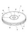
図1は、上記単にDVDディスク装置に使用される記録可能な光ディスク(DVDーRAMディスク)10の構造を説明する斜視図である。
図1に示すように、この光ディスク10は、それぞれ記録層16が設けられた一対の透明基板14を接着層20で貼り合わせた構造を持つ。各基板14は0.6mm厚のポリカーボネートで構成することができ、接着層20は極薄(例えば、40μm厚)の紫外線硬化性樹脂で構成することができる。これら一対の0.6mm基板14を、記録層16が接着層20の面上で接触するようにして貼り合わすことにより、1.2mm厚の大容量光ディスク10が得られる。
【0014】
光ディスク10には中心孔22が設けられ、ディスク両面の中心孔22の周囲には、この光ディスク10を回転駆動時にクランプするためのクランプエリア24が設けられている。中心孔22には、図示しないディスクドライブ装置に光ディスク10が装填された際に、ディスクモータのスピンドルが挿入される。そして、光ディスク10は、そのクランプエリア24において、図示しないディスククランパにより、ディスク回転中クランプされる。
【0015】
光ディスク10は、クランプエリア24の周囲に、コンピュータ・データ、ビデオデータ、オーディオデータその他の情報を記録することができる情報エリア25を有している。情報エリア25のうち、その外周側にはリードアウト・エリア26が設けられている。また、クランプエリア24に接する内周側にはリードイン・エリア27が設けられている。そして、リードアウト・エリア26とリードイン・エリア27との間にデータ記録エリア28が定められている。
【0016】
情報エリア25の記録層(光反射層)16、例えば、相変化記録層には、記録トラックがたとえばスパイラル状に連続して形成されている。その連続トラックは複数の物理セクタに分割され、これらのセクタには連続番号が付されている。このセクタを記録単位として、光ディスク10に種々なデータが記録される。
【0017】
データ記録エリア28は、実際のデータ記録領域であって、記録・再生情報として、コンピュータ・データ、映画等のビデオデータ(主映像データ)、字幕・メニュー等の副映像データおよび台詞・効果音等のオーディオデータが、同様なピット列(レーザ反射光に光学的な変化をもたらす物理的な形状あるいは相状態)として記録されている。
【0018】
このようなDVD−Rディスクへのデータ書き込みは、たとえば波長650nmで出力6〜12mW程度の半導体レーザを用いて行うことができる。
上記各種の光ディスク10において、読み書き用の記録層16を持つ基板14には、トラッキング・ガイドとして連続のグルーブ溝がスパイラル状に刻まれている。このグルーブ溝間にはランド部分が設けられるが、読み書き用DVDーRAMディスクにあっては、グルーブ溝内並びにランド部分に相変化記録層が設けられる構造を有し、グルーブ内の相変化記録層のみでなくランド部分の相変化記録層も情報記録に利用される。
【0019】
後述するDVDディスク装置は、DVDーRAMディスクに対する反復記録・反復再生(読み書き)及びDVDーROMディスクに対する反復再生が可能なように構成される。
【0020】
図2は、図1の光ディスク(DVDーRAM)10のデータ記録エリア28とそこに記録されるデータの記録トラックとの対応関係を説明する図である。
ディスク10がDVD−RAMの場合は、デリケートなディスク面を保護するために、即ち、ゴミ或いは油脂等がその表面に付着することを防ぐ為に、ディスク10の本体が後述するカートリッジ11に収納される。DVD−RAMディスク10がカートリッジ11ごと後述するDVDビデオレコーダのディスクドライブに挿入されると、カートリッジ11からディスク10が引き出されて図示しないスピンドルモータのターンテーブルにクランプされ、図示しない光ヘッドに向き合うようにして回転駆動される。
【0021】
図1に示した情報エリア25の記録層16には、データ記録トラックがスパイラル状に連続して形成されている。その連続するトラックは、図2に示すように一定記憶容量の複数論理セクタ(最小記録単位)に分割され、この論理セクタを基準にデータが記録されている。1つの論理セクタの記録容量は、1パックデータ長と同じ2048バイトに定められている。
【0022】
データ記録エリア28には、実際のデータ記録領域であって、管理データ、コンピュータ・データ或いはビデオ・データ、副映像データおよびオーディオ・データが同様に記録されている。
【0023】
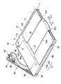
図3に示すように、光ディスク(DVDーRAM)10がディスクカートリッジ11に収納されたディスク・ユニットとして取り扱い可能である。このディスクカートリッジ11は、偏平な矩形状のケース12を備え、このケース12は、ほぼ同一構造を有する一対のハーフケース13a、13bを接合することにより形成されている。
【0024】
光ディスク10の表面と対向しているケース12の上壁および下壁、つまり、ハーフケース13a、13bの主壁11a、11bには、光ディスク14へアクセスするための窓部17がそれぞれ形成され、互いに対向している。各窓部17は、それぞれケース12のほぼ中央から、ディスクカートリッジ11の挿入方向Aに向かって、ケース12の前端面12a近傍まで延びている。
【0025】
ケース12には、窓部36を開閉する両面一体型のシャッタ32が摺動自在に取り付けられ、このシャッタ32が開かれることによって窓部17を介して光ディスク14の両面の一部が露出される。シャッタ22は、それぞれ窓部17を開閉する一対の矩形状の遮蔽板22aと、これら遮蔽板の前端同志を連結しているとともにケース前端面12aと対向した連結板22bと、を有し、断面U字形状に形成されている。そして、シャッタ22は、ケース12の前端面12a側からケース12の両表面側を挟むようにして取り付けられている。
【0026】
シャッタ22は、図4に示すように、窓部17を閉塞する閉塞位置と、図3に実線および2点鎖線でそれぞれ示すように、閉塞位置の両側に位置しそれぞれ窓部17を開放する2つの開放位置と、の間をケース12の前端面12aと平行な方向Gに沿って摺動可能となっている。シャッタ22は、ケース12内で窓部17の両側に配設された図示しない2つのシャッタばねにより常時閉塞位置に向かって付勢されている。
【0027】
ハーフケース13a、13bの表面の内、シャッタ22の遮蔽板22aが摺動する領域は、浅い矩形状の凹所35として形成され、窓部17もこの凹所内に形成されている。また、ハーフケース13a、13bは、凹所35の後端中央部から窓部17の近傍まで突出した抜け止め用の突部37を有し、この突部37は、遮蔽板32aの自由端部と係合して遮蔽板を凹所15内に保持している。
【0028】
ケース12の後端面は開口し、ケースに対して光ディスク10を出入れするためのディスク出し入れ口30が形成され、ケース後端面の全長に亘って延びている。また、ケース12には、このディスク出し入れ口30を開閉するための蓋部材34が回動自在に取付けられている。蓋部材34は、閉塞位置においてケース12の後壁12eを構成している。そして、蓋部材34を開放位置へ回動させることにより、ディスク出し入れ口30を通して、光ディスク10をケース12から取出し、およびケース12内へ装填することができる。
【0029】
図1に示すように、ケース12の一方の側壁12cの前半部にはガイドスロット7が形成され、カートリッジの挿入方向Aに沿ってケース前端面12aまで伸びている。図示しないDVDディスク・ドライブ装置へディスクカートリッジを装填する際、ガイドスロット7が光ディスクドライブ側に設けられたガイドピンと係合し、光ディスクカートリッジの装填をガイドする。
【0030】
各ハーフケース13a、13bの主壁11a、11bの後端部中央、および蓋部材24からなる後端面12e中央部には、ラベル貼付部6が連続して形成されている。また、蓋部材24において、ラベル貼付部6の両側には、一対の矩形状の凹所33が形成されている。これらの凹所33は、ディスクカートリッジ11を垂直に立てて使用する際、光ディスクドライブ側の突起とそれぞれ係合する。ケース12の両側壁12b、12cの後端部には、光ディスクドライブ側の把持機構を引っ掛けるための把持スロット36がそれぞれ形成されているとともに、両側壁12b、12cの前端部には、光ディスクドライブ側のローディング機構を引っ掛けるための凹所39がそれぞれ形成されている。
【0031】
図3および図4に示すように、主壁11aの内、ディスク出し入れ口20側の他方の角部、つまり、ディスクカートリッジ11の挿入方向Aに向かって左側の角部には、後述するライトプロテクト操作部を操作するための細長い操作孔8、および蓋部材34の開閉を検知するための円形の開口9が形成されている。
【0032】
主壁11aを上に向けた状態でディスクカートリッジ10を図示しない光ディスクドライブへ装填した際、光ディスクドライブ側に設けられた凸部がアライメントホール5aおよびロケーションホール5bに挿通され、光ディスクカートリッジが光ディスクドライブに対して位置決めされる。
【0033】
図4に示すように、蓋部材24は、ケース12の幅とほぼ等しい長さおよびケース12内へ挿入可能な厚さを有する細長い偏平な板状に形成された蓋本体38と、蓋本体の一側縁に形成されケースの全幅に亘って延びるフランジ40と、を有している。蓋部材34は、その長手方向一端が、枢軸(図示せず)を介して、ケース12の後端右角部に回動自在に支持されている。それにより、蓋部材24は、枢軸の回りで、閉塞位置と開放位置との間を回動し、ディスク出し入れ口20を開閉可能となっている。
【0034】
蓋部材34の自由端部、つまり、枢軸と反対側の端部には、弾性変形可能なロック爪46が設けられ、また、ケース12の左壁12c後端部には、ロック爪46が係合可能な係止孔47が形成されている。それにより、蓋部材34がディスク出し入れ口20を閉塞する位置に回動すると、ロック爪46が係止孔47に係合して蓋部材34を閉塞位置にロックする。なお、ケース12の外面側から係止孔を介してロック爪46を押し込むことにより、ロックが解除され、蓋部材34を開放することが可能となる。
【0035】
蓋部材34の蓋本体38には、ライトプロテクト操作部50が弾性変形自在に一体成形されている。ライトプロテクト操作部50は、蓋本体38の幅方向のほぼ中央部からロック爪46側の端部に向かって延出したアーム50aと、アームの先端に設けられた駒部50bとを有している。そして、ライトプロテクト操作部40は、蓋本体38に形成された開口部内に位置し、アーム50aの基端のみが蓋本体に接続されている。これにより、ライトプロテクト操作部50の駒部50bは、アーム50aの基端を中心として、書き込み許容位置と書き込み禁止位置(ライトプロテクト位置)との間を回動可能となっている。
【0036】
蓋部材34を閉じた状態において、駒部50bはケース12に形成された操作孔8と対向して位置する。それにより、操作孔8を介してライトプロテクト操作部50を切り換えることができる。
【0037】
図5は、図1に示される2層光ディスクのRAM層のレイアウトを説明する図である。
すなわち、ディスク内周側のリードイン・エリア27は、光反射面が凹凸形状をしたエンボスゾーン、表面が平坦(鏡面)なミラーゾーンおよび書替可能ゾーンで構成される。エンボスゾーンは基準信号ゾーンおよび制御データゾーンを含み、ミラーゾーンは接続ゾーンを含む。
【0038】
書替可能ゾーンは、ディスクテストゾーンと、ドライブテストゾーンと、ディスクID(識別子)ゾーンと、欠陥管理エリアDMA1およびDMA2を含んでいる。
【0039】
ディスク外周側のリードアウト・エリア26は、欠陥管理エリアDMA3およびDMA4と、ディスクID(識別子)ゾーンと、ドライブテストゾーンと、ディスクテストゾーンを含む書替可能ゾーンで構成される。
【0040】
リードイン・エリア27とリードアウト・エリア26との間のデータエリア28は、24個の年輪状のゾーン00〜ゾーン23に分割されている。各ゾーンは一定の回転速度を持っているが、異なるゾーン間では回転速度が異なる。また、各ゾーンを構成するセクタ数も、ゾーン毎に異なる。具体的には、ディスク内周側のゾーン(ゾーン00等)は回転速度が早く構成セクタ数は少ない。一方、ディスク外周側のゾーン(ゾーン23等)は回転速度が遅く構成セクタ数が多い。このようなレイアウトによって、各ゾーン内ではCAVのような高速アクセス性を実現し、ゾーン全体でみればCLVのような高密度記録性を実現している。
【0041】
図6は、図5のレイアウトにおけるリードイン・エリアおよびリードアウト・エリアの詳細を説明する図である。
書換不能のエンボス・データ・ゾーンに属するリード・インの開始位置には、ブランク・ゾーンが設けられ、このブランク・ゾーンには、ブランクを意味する全て00hがセットされている。このエンボス・データ・ゾーンに続いて基準信号ゾーンが設けられ、基準信号ゾーンには、エンボス・基準コードが記録されている。エンボス・基準コードは、予め定められた変換テーブル中のコード・ワードが繰り返しされている。この所定のコード・ワードが正しく読み出されるように、換言すれば、所定のエラー率の範囲内で読み出されるように装置が設定される。この基準信号ゾーンに続いてまたブランク・ゾーンが設けられている。
【0042】
エンボス・データ・ゾーンの制御データゾーンには、適用されるDVD規格のタイプ(DVD−ROM・DVD−RAM・DVD−R等)およびパートバージョンと、ディスクサイズおよび最小読出レートと、ディスク構造(1層ROMディスク・1層RAMディスク・2層ROM/RAMディスク等)と、記録密度と、データエリアアロケーションと、バーストカッティングエリアの記述子と、記録時の露光量指定のための線速度条件と、読出パワーと、ピークパワーと、バイアスパワーと、媒体の製造に関する情報が記録されている。
【0043】
別の言い方をすると、この制御データゾーンには、記録開始・記録終了位置を示す物理セクタ番号などの情報記憶媒体全体に関する情報と、記録パワー、記録パルス幅、消去パワー、再生パワー、記録・消去時の線速などの情報と、記録・再生・消去特性に関する情報と、個々のディスクの製造番号など情報記憶媒体の製造に関する情報等が事前に記録されている。この制御データゾーンに続いて、また、ブランク・ゾーンが設けられている。
【0044】
ミラー・ゾーンには、接続ゾーンが設けられている。この接続ゾーンは、エンボス・データ・ゾーンと書換可能データゾーンとの接続の為に設けられ、グルーブもエンボス・マークも設けられていない。
【0045】
リードイン・エリア27およびリードアウト・エリア26の書替可能データゾーンには、各々の媒体ごとの固有ディスク名記録領域と、試し記録領域(記録消去条件の確認用)と、データエリア内の欠陥領域に関する管理情報記録領域が設けられている。これらの領域を利用することで、個々のディスクに対して最適な記録が可能となる。
【0046】
書換可能データ・ゾーンの先頭には、ガード・トラック・ゾーンが位置している。このガード・トラック・ゾーンは、グルーブ、ランド、ヘッド・フィールド及び記録フィールドを含んでいる。但し、記録フィールドには、データは、記録されていない。ガード・トラック・ゾーンに続いてディスク・テスト・ゾーンが設けられている。このディスク・テスト・ゾーンは、ディスク製造者による品質検査の為に設けられている領域であって、グルーブ、ランド、ヘッド・フィールド及び記録フィールドを含んでいる。このディスク・テスト・ゾーンに続くドライブ・テスト・ゾーンは、ドライブ、即ち、記録装置によるテスト為に設けられ、同様にグルーブ、ランド、ヘッド・フィールド及び記録フィールドを含んでいる。
【0047】
ドライブ・テスト・ゾーンに続くディスク識別ゾーンは、同様にグルーブ、ランド、ヘッド・フィールド及び記録フィールドを含んでいる。この領域には、記録可(W/P:ON)或い記録不可(W/P:OFF)のコマンドがユーザによって記録することが許されている。例えば、記録可(W/P:ON)のコマンドとして“10h”が記録され、記録不可(W/P:OFF)のコマンドとして“00h”が記録される。当然のことながら、ユーザがこのコマンドの書き込みをする場合には、リードイン・エリア27およびリードアウト・エリア26における両書替可能データゾーンのディスク識別ゾーンに記録可(W/P:ON)のコマンド、或いは、記録不可(W/P:OFF)のコマンドのいずれかが書き込まれる。
【0048】
既に説明したようにディスクカートリッジ11には、ライトプロテクト操作部50が設けられ、DVDディスク10にデータが記録可能(W/P:ON)であるか、或いは、記録不可(W/P:OFF)であるかがこのライトプロテクト操作部50によって判明する。DVDディスク10がディスクカートリッジ11から取り出された際には、ユーザは、DVDディスク10のディスク識別ゾーンの記述によって記録可(W/P:ON)或い記録不可(W/P:OFF)によってデータの書き込みが可能か否かを判断することとなる。DVDディスク10がディスクカートリッジ11に収納されている場合には、ライトプロテクト操作部50及びディスク識別ゾーンの両者が記録可(W/P:ON)及び記録不可(W/P:OFF)のいずれかに一致していれば、当然にその一致している記録可(W/P:ON)及び記録不可(W/P:OFF)の状態にDVDディスク10があることが判明する。これに対して、ライトプロテクト操作部50及びディスク識別ゾーンの両者が記録可(W/P:ON)及び記録不可(W/P:OFF)のいずれかに一致していない場合には、DVDディスク10が記録可(W/P:ON)及び記録不可(W/P:OFF)のいずれの状態にあるかは、ユーザの判断に委ねられることとなる。通常、ライトプロテクト操作部50及びディスク識別ゾーンの一方が記録不可(W/P:OFF)であれば、DVDディスク10が記録不可(W/P:OFF)である可能性が十分にあることから、ユーザは、そのDVDディスク10は、記録不可(W/P:OFF)であるとしてそのデータの内容を確認することとなる。データの確認を終えた後、ライトプロテクト操作部50及びディスク識別ゾーンの両者を記録可(W/P:ON)及び記録不可(W/P:OFF)のいずれの状態に一致させることとなる。いずれにしても、ライトプロテクト操作部50及びディスク識別ゾーンを利用してDVDディスク10が記録可(W/P:ON)及び記録不可(W/P:OFF)の状態にあるかを判断可能であるのでよりディスク10の書き込みに関する安全度が向上される。
【0049】
図6に示すようにリードイン・エリア27の書換可能データ・ゾーンは、欠陥管理エリアDMA1およびDMA2を含み、同様にリードアウト・エリア26は、同様の欠陥管理エリアDMA3およびDMA4を含んでいる。
【0050】
ディスク識別ゾーンに続いて欠陥管理エリア(DMA1〜DMA4)が設けられている。この管理エリア(DMA1〜DMA4)はデータエリアの構成および欠陥管理の情報を含むもので、たとえば32セクタで構成される。各欠陥管理エリア(DMA1〜DMA4)の後には、適宜予備のセクタ(スペアセクタ)が付加されている。各欠陥管理エリア(DMA1〜DMA4)は、2つのECCブロックからなる。各欠陥管理エリア(DMA1〜DMA4)の最初のECCブロックには、ディスク10の定義情報構造(DDS; Disc Definition Structure)および一次欠陥リスト(PDL; PrimaryDefect List)が含まれる。各欠陥管理エリア(DMA1〜DMA4)の2番目のECCブロックには、二次欠陥リスト(SDL; Secondary Defect List)が含まれる。4つの欠陥管理エリア(DMA1〜DMA4)の4つの一次欠陥リスト(PDL)は同一内容となっており、それらの4つの二次欠陥リスト(SDL)も同一内容となっている。
【0051】
この欠陥管理エリア(DMA1〜DMA4)には、欠陥情報に関しての物理アドレスが記載され、この欠陥に関する物理アドレスを参照してデータの記録が実行され、また、データが再生される。
【0052】
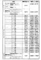
欠陥管理エリア(DMA1〜DMA4)に続いて、換言すれば、リードイン・エリア27とリードアウト・エリアの間には、データが記録されるデータ領域28が設けられている。このデータエリア28は、半径方向に複数(1888)のトラックからなる複数たとえば24のゾーンにより構成されている。また、各ゾーンごとに、ゾーン番号、1トラック(1周あたり)のセクタ数、スタートセクタ番号(ヘキサ)、内周側のガードエリアのセクタ番号(ヘキサ)、グループ番号、ユーザエリアのセクタ番号(ヘキサ)とECCブロック数、スペアエリアのセクタ番号(ヘキサ)とセクタ数、外周側のガードエリアのセクタ番号(ヘキサ)、エンドセクタ番号(ヘキサ)、グループのスタートセクタ番号、グループのスタートセクタ番号(ヘキサ)が記録されている。
【0053】
次に図7を参照して上述したDVDディスクへのデータの記録及びDVDディスクからデータを再生するDVDディスク装置の一例について説明する。
図7に示されたDVDディスク装置は、DVDディスクのみならずCDディスクからもデータの読み出しが可能で、書換可能なDVDディスクに対してデータの書き込みが可能な装置として構成されている。従って、光ピック・アップ60は、DVD用の対物レンズ62及びCD用の対物レンズ64を有している。光ピック・アップ60内には、DVD用の対物レンズ62及びCD用の対物レンズ64に対応してDVD用及びCD用の半導体レーザ・ユニット(図示せず)が設けられ、装填された光ディスク10がDVDディスク或いはCDディスクかに応じてこの半導体レーザ・ユニットの一方が選択され、レーザ制御ユニット66によって附勢され、それぞれ対応する波長のレーザ・ビームを発生する。DVD用及びCD用の半導体レーザ・ユニットのいずれかが選択されて附勢されると、光ディスク10に対応するレーザ・ビームが対応する対物レンズ62、64に向けられ、この対物レンズ62、64によって光ディスク10に収束される。この収束されたレーザ・ビームで光ディスク10にデータが書き込まれ、或いは、再生される。
【0054】
レーザ制御ユニット66は、DVDデータ処理ユニット80によってその設定がセットされるが、その設定は、再生信号を得る再生モード、データを記録する記録モード及びデータを消去する消去モード並びにDVDディスクに対するデータ処理を実行するDVDモード及びCDディスクに対するデータ処理を実行するCDモードで異なっている。即ち、DVDモードでは、DVD用の半導体レーザ・ユニットが選択されて附勢され、また、CDモードでは、CD用の半導体レーザ・ユニットが選択されて附勢される。DVD用或いはCD用のレーザ・ビームは、再生モード、記録モード及び消去モードの3つのモードでそれぞれ異なるレベルのパワーを有し、そのモードに対応したパワーのレーザビームが発生されるように半導体レーザ・ユニットがレーザ制御ユニット66によって附勢される。
【0055】
DVD用の対物レンズ62及びCD用の対物レンズ64に対向してDVDディスク10或いはCDディスクが配置されるように、このDVDディスク或いはCDディスクは、直接或いはディスク・カートリッジ11に収納されてトレー70によって装置内に搬送される。このトレー70を駆動する為のトレーモータ72が装置内に設けられている。また、装填されたDVDディスク10或いはCDディスクは、スタンパ74によって回転可能にスピンドル・モータ75上に保持され、このスピンドル・モータ75によって回転される。ピックアップ・ヘッド60は、送りモータ76によって駆動される送り機構(図示せず)上に載置され、この送り機構によって光ディスク10の半径方向に移動される。トレー70の下方には、ライトプロテクト検出部71が設けられ、このライトプロテクト検出部71によってディスク・カートリッジ11が書き込み可或いは書き込み不可に設定されているかを検出することができる。
【0056】
ピックアップ・ヘッド60は、その内にレーザビームを検出する検出器(図示せず)を有している。この光検出器は、光ディスク10で反射されて対物レンズ62、64を介して戻されたレーザ・ビームを検出している。検出器からの検出信号(電流信号)は、電流/電圧変換器77で電圧信号に変換され、この信号は、リファレンス・アンプ78及びサーボ・アンプ79に供給される。リファレンス・アンプ78からは、加算信号としての再生信号がDVDデータ処理ユニット80に出力される。サーボ・アンプ79からのサーボ信号は、DVDモードでは、DVDサーボ・シーク制御ユニット82に出力され、CDモードでは、CDサーボ・シーク制御並びにCDデータ処理ユニットに出力される。
【0057】
DVDモードでは、DVDサーボ・シーク制御ユニット82からフォーカス信号、トラッキング信号及び送り信号がフォーカス及びトラッキング・アクチュエータ・ドライバ並びに送りモータドライバ84に送られ、このドライバ84によって対物レンズ62、64がフォーカス・サーボ制御され、また、トラッキング・サーボ制御される。更に、アクセス信号に応じてドライバ84から附勢信号が送りモータ76に供給されピックアップ・ヘッド60が搬送制御される。このDVDサーボ・シーク制御ユニット82は、DVDデータ処理ユニット82によって制御される。例えば、DVDデータ処理ユニット82からアクセス信号がDVDサーボ・シーク制御ユニット82に供給されて送り信号が生成される。また、DVDデータ処理ユニット82からの制御信号でスピンドル・モータ・ドライバ85及びトレー・モータ・ドライバ86が制御され、スピンドルモータ75及びトレー・モータ72が附勢され、スピンドル・モータが所定回転数で回転され、トレーモータがトレーを適切に制御することとなる。DVDデータ処理ユニット80に供給された再生信号は、RAM87に必要なデータが格納され、再生信号がこのDVDデータ処理ユニット80で処理されてバッファとしてのRAM89を有するSCSIインタフェース制御部並びにCD−ROMデコーダ88に供給され、SCSIを介して他の装置、例えば、パーソナル・コンピュータに再生処理信号が供給される。
【0058】
CDモードでは、CDサーボ・シーク制御並びにCDデータ処理ユニット83からフォーカス信号、トラッキング信号及び送り信号がフォーカス及びトラッキング・アクチュエータ・ドライバ並びに送りモータドライバ84に送られ、このドライバ84によって対物レンズ62、64がフォーカス・サーボ制御され、また、トラッキング・サーボ制御される。更に、アクセス信号に応じてドライバ84から附勢信号が送りモータ76に供給されピックアップ・ヘッド60が搬送制御される。このCDサーボ・シーク制御並びにCDデータ処理ユニット83からの制御信号でスピンドル・モータ・ドライバ85及びトレー・モータ・ドライバ86が制御され、スピンドルモータ75が附勢され、スピンドル・モータが所定回転数で回転されることとなる。CDデータ処理ユニット83に供給された再生信号は、この処理ユニット83で処理されてCDデータ出力アンプ90を介して出力される。
【0059】
図7に示す各部は、ROM91に格納された手順に従って、CPU92によって制御される。
次に、書換可能なDVDディスクが装填されてからデータの記録開始までの動作を説明する。ここで、DVDディスク10は、ディスク・カートリッジ11に収納されているものとする。
【0060】
ディスク・カートリッジ11がトレー70に載置されて図示しない入力手段、キーボード等でその装置内への格納を指示すると、ディスク・カートリッジ11は、装置内に格納され、そのシャッタ22が開かれ、DVDディスク10が露出され、スタンパ74によって保持される。スタンパによってDVDディスク10保持されると、DVDデータ処理ユニット80からの指令でスピンドル・モータ・ドライバ85が附勢されたスピンドル・モータ75が作動される。その結果、DVDディスク10が回転を開始する。このディスクの装填時にディスク・カートリッジ11のライトプロテクト操作部50がライトプロテクト検出部71によって検出され、そのディスク・カートリッジ11内のDVDディスクが記録可のディスクか或いは、記録不可かが確認される。この記録可、或いは、記録不可の識別コード・データは、ディスク・カートリッジの書替情報としてRAM94に格納される。
【0061】
DVDデータ処理ユニット80は、レーザ制御ユニット66をDVDモードにセットし、しかも、再生モードにセットしてピック・アップ・ヘッド60内の半導体レーザ・ユニットからDVD用の波長を有する再生用レーザ・ビームを発生させる。また、DVDデータ処理ユニット80は、DVDサーボ・シーク制御ユニット82に対してピックアップの送りを開始する指令を与え、このDVDサーボ・シーク制御ユニット82は、この指令に基づいてドライバ84を附勢させて送りモータ76を作動させる。その結果、送りもモータが作動してホーム・ポジションに位置されているピック・アップ・ヘッド60がリードイン・エリア27に移動され、リードイン・エリア27が再生用レーザ・ビームで検索される。このリードイン・エリア27の検索中において、検出器79からの信号は、RFアンプ78及びサーボアンプ79に供給され、RFアンプ78からの出力は、DVDデータ処理ユニットで80で処理されて再生信号としてユニット88及びSCSIを介して外部装置例えば、パーソナル・コンピュータに供給される。サーボアンプ79からの出力は、DVDサーボ・シーク制御ユニット82でフォーカス信号及びトラッキング信号に変換されてドライバ84に供給され、このドライバ84からの信号で対物レンズ62にフォーカス・サーボ並びにトラッキング・サーボが与えられて対物レンズ62は、フォーカス並びにトラッキング状態に維持されてレーザ・ビームでトラッキング・ガイド内のデータが読み出される。
【0062】
データの読み出しに際しては、図6に示すブランクゾーンであることが確認され、ブランクゾーンに続く基準信号ゾーンの基準信号によってエラー率が所定範囲内に入るようにDVDデータ処理ユニット80がセットされる。更に、基準信号ゾーンに続くブランクゾーンが確認され、ブランクゾーンに続く制御データゾーンを読み出してその制御データに従って装置の各部がセットされる。更に、制御データゾーンに続くブランクゾーンが確認され、ブランクゾーンに続く接続ゾーンを読みだしてエンボス・データ・ゾーンの読み込みが終了したことが確認される。その後、書替可能データゾーンのドガード・トラック・ゾーン、ディスク・テスト・ゾーンが確認されて、ドライブ・テスト・ゾーンで当該装置で読み書き可能かがテストされる。ドライブ・テスト・ゾーンに続くガード・トラック・ゾーンが確認され、ディスク識別子ゾーンが読み込まれる。ディスク10のイニシャル時には、このディスク識別子ゾーンに記録可(W/P:ON)が書き込まれる。また、ディスク10のイニシャル後においては、このディスク識別子ゾーンの記録可(W/P:ON)或いは記録不可(W/P:OFF)の識別コード・データが読み出され、ディスクの書替情報としてRAM94に格納される。
【0063】
その後、欠陥管理エリア(DMA1&DMA2)が読み込まれてRAM94に格納され、当該ディスク10の欠陥領域が特定される。この処理の後、再生モードであれば、データ領域からデータが読み出され、記録モードにおいては、データ領域の所定の領域にデータが書き込まれる。データ再生後、或いは、データ記録後、ユーザに対して当該ディスクへのデータの記録を許すか否かの問い合わせが表示装置を用いてなされる。ユーザが当該ディスクへのデータの記録を許すことを希望する場合には、記録可(W/P:ON)の識別コード・データがリードイン・エリア及びリードアウト・エリア26のディスク識別子ゾーンに書き込まれる。同様に、ユーザが当該ディスクへのデータの記録を禁止ことを希望する場合には、記録不可(W/P:OFF)の識別コード・データがリードイン・エリア及びリードアウト・エリア26のディスク識別子ゾーンに書き込まれる。
【0064】
記録モードにおいて、ユーザが外部からデータの記録の指示をした場合には、RAM94に格納され記録可或いは不可の2つの識別コード・データが参照される。2つの識別コード・データの内いずれかに記録不可の識別コード・データが設定されている場合には、その記録不可の識別コード・データを参照してその旨を表示部(図示せず)に表示してユーザに書き込み不可である旨を知らせる。また、ユーザが記録モードを設定してもCPUは、その記録モードの設定を無効にする処理をすることとなる。この場合、ディスクカートリッジ11は、記録不可(W/P:OFF)、ディスク識別子ゾーンは、記録可(W/P:ON)並びにディスクカートリッジ11は、記録可(W/P:ON)並びにディスク識別子ゾーンは、記録不可(W/P:OFF)、或いは、ディスクカートリッジ11は、記録不可(W/P:OFF)並びにディスク識別子ゾーンは、記録不可(W/P:OFF)と表示してユーザに対して光ディスクに関しての状態を問い合わせるようにしても良い。ユーザは、この光ディスクに関しての状態を参照して再生モードとするか或いは記録モードとするか決定することとなる。ディスク識別子が記録不可(W/P:OFF)の場合には、ディスク識別子を記録可(W/P:ON)に書き替えない限り、CPUは、原則としてその記録モードの設定を無効にする処理をすることとなる。従って、ユーザは、ディスク識別子が記録不可(W/P:OFF)であることを認識した場合には、ディスク識別子ゾーンに記録可(W/P:ON)の書き込み処理をした後、再度、装置を記録モードに設定することが要求される。
【0065】
上述した動作の説明は、DVDディスク10がディスク・カートリッジ11に収納されているものとしているが、ディスク・カートリッジ11からDVDディスク10が取り出されたり、或いは、DVDディスク10のみをユーザが受け取ってそのDVDディスク10のみを装置に装填した状態では、ディスク・カートリッジ11に関する表示がなされず、単に、ディスク識別子ゾーンの記録不可(W/P:OFF)或いは記録可(W/P:ON)のみが表示される。この表示に基づいてユーザは、再生モードとするか或いは記録モードとするかを決定することとなる。
【0066】
【発明の効果】
以上のようにDVDディスク10のリードイン・エリア及びリードアウト・エリアにディスク識別子ゾーンが設けられ、ディスク識別子ゾーンに記録不可(W/P:OFF)或いは記録可(W/P:ON)の識別コード・データを記録することができ、この識別コード・データでDVDディスク10に記録可能か否かをユーザが確認することができる。従って、DVDディスク10自体がディスク・カートリッジ11から取り出されても、また、ディスク・カートリッジ11とは別体でDVDディスク10が販売され、取り扱われても、それ自体で記録可能か否かをユーザが確認することができる。
【図面の簡単な説明】
【図1】この発明の一実施例に係るDVDディスクを概略的に示す斜視図である。
【図2】図1に示されたDVDディスクのフォーマット構造を示す平面図である。
【図3】図2に示されたディスク・カートリッジを示す斜視図である。
【図4】図3に示されたディスク・カートリッジにおいて、その内のディスクを取り出すための蓋部材を開いた状態を示す斜視図である。
【図5】図2に示されたDVDーRAMディスクのレイアウトを示す配置図である。
【図6】図1、図2及び図5に示されたリードイン・エリアのフォーマットを示す配置図である。
【図7】図1、図2及び図5に示すDVDーRAMディスクからデータを再生し、このディスクにデータを記録する再生記録用DVDディスク装置を示すブロック図である。
【符号の説明】
10…光ディスク
11…カートリッジ
12…ケース
16…記録層
17…窓部
22…シャッタ
25…情報エリア
28…データ記録エリア
30…ディスク出し入れ口
34…蓋部材
40…フランジ
46…ロック爪
47…係止口
50…ライトプロテクト操作部
62、64…対物レンズ
66…レーザ制御ユニット
60…ピックアップ・ヘッド
70…トレー
76…送りモータ
77…電流/電圧変換器
80…DVDデータ処理ユニット
83…CDデータ処理ユニット
88…CD−ROMデコーダ
92…CPU[0001]
BACKGROUND OF THE INVENTION
The present invention relates to a data rewritable optical disc, and in particular, an optical disc is a rewritable type, but an area is provided in which identification code data for prohibiting data recording on the optical disc can be recorded. The present invention relates to a rewritable optical disc.
[0002]
[Prior art]
In recent years, various types of optical disks have emerged due to diversification of CD-ROM formats and the advent of DVDs, and various types of disks may be developed and appear in the future. For example, a normal CD includes a music CD, and a CD-ROM format includes a read-only CD-ROM, a writable CDR, a CDR2 readable at different wavelengths, an erasable CD-E, and the like. . In addition, DVDs include a single-layer disc, a dual-layer disc, a writable DVD-R, and a DVD-R that can be written and read. These DVD disc apparatuses are required to be able to record data on writable optical discs and to be able to reproduce data from various optical discs.
[0003]
Various proposals have been made for a disk device that can write on a writable optical disk and can reproduce data not only on various optical disks and DVD disks but also on a CD. It has been.
[0004]
Against this background, whether or not data can be written is important even if the optical disk loaded in the disk device is found to be a rewritable optical disk. If it is not clear that the data can be written, even if erasable data is recorded on the rewritable optical disk, the data may be recorded without knowing that the data cannot be erased. .
[0005]
In a conventional rewritable CD, that is, CD-E, it is stored in a case and a non-rewritable slide button is provided on the case, and the rewritable or non-rewritable is set by sliding the slide button. The For example, when the button of the case is moved to a non-rewritable position, a light transmission hole is provided in the case, and it is determined that the case cannot be rewritten by determining that the hole is present. .
[0006]
[Problems to be solved by the invention]
In such a type, it is always determined whether the rewritable CD is rewritable or impossible when integrated with the case, and if the rewritable CD is separated from the case, is the disk rewritable or impossible? There is a problem that is not known. For the user, it is preferable that the optical disk can be taken out of the case and played back by a playback-only playback device. In particular, in a playback device for DVD-ROM or DVD-VIDEO, which is a playback-only DVD optical disc, the DVD-ROM or DVD-VIDEO disc is not stored in the case but is loaded and played as it is. Of course, there is a demand for reproducing a rewritable DVD disc by such a reproduction-only reproducing apparatus, and the DVD disc may be taken out of the case. Further, there is a case where reproduction is requested with a recording DVD device in the taken out state, and there is a possibility that a writing operation is erroneously performed at that time. There is also a desire to erase the data on the disc and write the data again after the user removes the rewritable DVD disc from the case.
[0007]
[Means for Solving the Problems]
The present invention is provided with two systems of
[0011]
DETAILED DESCRIPTION OF THE INVENTION
Hereinafter, an optical disk showing an embodiment of the present invention will be described with reference to the drawings.
A digital information recording / reproducing system according to an embodiment of the present invention will be described below with reference to the drawings.
[0012]
As a typical embodiment of a digital information recording / reproducing system according to the present invention, an apparatus for recording and reproducing computer data or a moving image encoded based on MPEG2 at a variable bit rate (hereinafter simply referred to as a DVD disk apparatus). Called).
[0013]
FIG. 1 is a perspective view for explaining the structure of a recordable optical disk (DVD-RAM disk) 10 simply used in the DVD disk device.
As shown in FIG. 1, the
[0014]
A
[0015]
The
[0016]
In the recording layer (light reflecting layer) 16 of the
[0017]
The
[0018]
Data writing to such a DVD-R disk can be performed using, for example, a semiconductor laser having a wavelength of 650 nm and an output of about 6 to 12 mW.
In the various
[0019]
A DVD disk device described later is configured to be able to perform repetitive recording / repetitive reproduction (read / write) on a DVD-RAM disk and repetitive reproduction on a DVD-ROM disk.
[0020]
FIG. 2 is a diagram for explaining the correspondence between the
When the
[0021]
In the
[0022]
The
[0023]
As shown in FIG. 3, an optical disk (DVD-RAM) 10 can be handled as a disk unit housed in a
[0024]
[0025]
A double-sided
[0026]
As shown in FIG. 4, the
[0027]
Of the surfaces of the
[0028]
The rear end surface of the
[0029]
As shown in FIG. 1, a
[0030]
At the center of the rear end of the
[0031]
As shown in FIGS. 3 and 4, a write protect described later is provided at the other corner of the
[0032]
When the
[0033]
As shown in FIG. 4, the
[0034]
An elastically
[0035]
A write protect
[0036]
In the state where the
[0037]
FIG. 5 is a diagram for explaining the layout of the RAM layer of the two-layer optical disk shown in FIG.
That is, the lead-in
[0038]
The rewritable zone includes a disk test zone, a drive test zone, a disk ID (identifier) zone, and defect management areas DMA1 and DMA2.
[0039]
The lead-
[0040]
A
[0041]
FIG. 6 is a diagram for explaining the details of the lead-in area and lead-out area in the layout of FIG.
A blank zone is provided at the start position of the lead-in belonging to the non-rewritable emboss data zone, and all blanks 00h are set in the blank zone. A reference signal zone is provided subsequent to the emboss data zone, and an emboss reference code is recorded in the reference signal zone. For the emboss / reference code, a code word in a predetermined conversion table is repeated. The apparatus is set so that the predetermined code word is read correctly, in other words, within a predetermined error rate range. Following this reference signal zone, a blank zone is also provided.
[0042]
The control data zone of the embossed data zone includes the type of DVD standard (DVD-ROM, DVD-RAM, DVD-R, etc.) and part version, disc size and minimum read rate, disc structure (1 Layer ROM disk, 1 layer RAM disk, 2 layer ROM / RAM disk, etc.), recording density, data area allocation, burst cutting area descriptor, and linear velocity condition for specifying the exposure amount during recording, Information relating to read power, peak power, bias power, and production of the medium is recorded.
[0043]
In other words, the control data zone includes information on the entire information storage medium such as the physical sector number indicating the recording start / end position, recording power, recording pulse width, erasing power, reproducing power, recording / erasing. Information such as the linear velocity at the time, information relating to recording / reproducing / erasing characteristics, information relating to the manufacture of the information storage medium such as the serial number of each disc, and the like are recorded in advance. Following this control data zone, a blank zone is also provided.
[0044]
A connection zone is provided in the mirror zone. This connection zone is provided for the connection between the embossed data zone and the rewritable data zone, and no groove or embossed mark is provided.
[0045]
In the rewritable data zone of the lead-in
[0046]
A guard track zone is located at the beginning of the rewritable data zone. The guard track zone includes a groove, a land, a head field, and a recording field. However, no data is recorded in the recording field. A disk test zone is provided after the guard track zone. The disk test zone is an area provided for quality inspection by the disk manufacturer, and includes a groove, a land, a head field, and a recording field. The drive test zone following this disk test zone is provided for testing by a drive, ie, a recording device, and similarly includes a groove, a land, a head field, and a recording field.
[0047]
The disc identification zone following the drive test zone also includes a groove, land, head field and recording field. In this area, the user is allowed to record a command indicating whether recording is possible (W / P: ON) or recording is impossible (W / P: OFF). For example, “10h” is recorded as a record enable (W / P: ON) command, and “00h” is recorded as a record disable (W / P: OFF) command. Of course, when the user writes this command, it is possible to record in the disc identification zone of both rewritable data zones in the lead-in
[0048]
As described above, the
[0049]
As shown in FIG. 6, the rewritable data zone of the lead-in
[0050]
Subsequent to the disc identification zone, defect management areas (DMA1 to DMA4) are provided. This management area (DMA1 to DMA4) includes data area configuration and defect management information, and is composed of, for example, 32 sectors. A spare sector (spare sector) is appropriately added after each defect management area (DMA1 to DMA4). Each defect management area (DMA1 to DMA4) is composed of two ECC blocks. The first ECC block of each defect management area (DMA1 to DMA4) includes a definition information structure (DDS; Disc Definition Structure) and a primary defect list (PDL) of the
[0051]
In this defect management area (DMA1 to DMA4), a physical address related to defect information is described, data recording is executed with reference to the physical address related to the defect, and data is reproduced.
[0052]
Following the defect management area (DMA1 to DMA4), in other words, a
[0053]
Next, an example of a DVD disk device that records data on the DVD disk and reproduces data from the DVD disk will be described with reference to FIG.
The DVD disk device shown in FIG. 7 is configured as a device that can read data not only from a DVD disk but also from a CD disk and can write data to a rewritable DVD disk. Therefore, the optical pick-
[0054]
The settings of the
[0055]
The DVD disk or CD disk is stored directly or in the
[0056]
The
[0057]
In the DVD mode, a focus signal, a tracking signal, and a feed signal are sent from the DVD servo / seek
[0058]
In the CD mode, a focus signal, a tracking signal and a feed signal are sent from the CD servo seek control and CD
[0059]
Each unit shown in FIG. 7 is controlled by the
Next, operations from when a rewritable DVD disc is loaded to when data recording starts will be described. Here, it is assumed that the
[0060]
When the
[0061]
The DVD
[0062]
At the time of reading data, it is confirmed that the blank zone is shown in FIG. 6, and the DVD
[0063]
Thereafter, the defect management area (DMA1 & DMA2) is read and stored in the
[0064]
In the recording mode, when the user instructs to record data from the outside, two identification code data stored in the
[0065]
In the above description of the operation, it is assumed that the
[0066]
【The invention's effect】
As described above, the disc identifier zone is provided in the lead-in area and the lead-out area of the
[Brief description of the drawings]
FIG. 1 is a perspective view schematically showing a DVD disc according to an embodiment of the present invention.
FIG. 2 is a plan view showing a format structure of the DVD disc shown in FIG. 1;
FIG. 3 is a perspective view showing the disk cartridge shown in FIG. 2;
4 is a perspective view showing a state in which a lid member for taking out a disk in the disk cartridge shown in FIG. 3 is opened. FIG.
FIG. 5 is a layout diagram showing a layout of the DVD-RAM disk shown in FIG. 2;
6 is a layout view showing a format of the lead-in area shown in FIGS. 1, 2, and 5. FIG.
7 is a block diagram showing a reproducing / recording DVD disc apparatus for reproducing data from the DVD-RAM disc shown in FIGS. 1, 2 and 5 and recording data on the disc. FIG.
[Explanation of symbols]
10 ... Optical disc
11 ... cartridge
12 ... Case
16: Recording layer
17 ... Window
22 ... Shutter
25 ... Information area
28 ... Data recording area
30: Disc entry / exit
34 ... Lid member
40 ... Flange
46 ... Lock claw
47 ... Stopper
50: Write protect operation section
62, 64 ... Objective lens
66 ... Laser control unit
60 ... Pickup head
70 ... Tray
76 ... Feed motor
77 ... Current / voltage converter
80 ... DVD data processing unit
83 ... CD data processing unit
88 ... CD-ROM decoder
92 ... CPU
Claims (3)
Translated fromJapanese前記リードイン・エリアは、書換できないデータが記録されているエンボス・ゾーン、書換可能なデータ領域としての書換可能ゾーン及びその両者間のミラー領域を有し、また、前記リードアウト・エリアは、書換可能なデータ領域としての書換可能ゾーンを有し、The lead-in area has an emboss zone in which non-rewritable data is recorded, a rewritable zone as a rewritable data area, and a mirror area between the two, and the lead-out area has a rewritable area. Has a rewritable zone as a possible data area,
前記リードイン・エリア及び前記リードアウト・エリアの書換可能ゾーンは、ディスクを識別する識別情報としてデータ記録エリアのデータを書換ることができない旨の書換不可、或いは、データ記録エリアのデータを書換ることができる旨の書換可能を示す識別子をユーザが記録することができるディスク識別子領域が設けられている光ディスクと、The rewritable zones of the lead-in area and the lead-out area cannot be rewritten to the effect that data in the data recording area cannot be rewritten as identification information for identifying the disc, or the data in the data recording area is rewritten. An optical disc provided with a disc identifier area in which a user can record an identifier indicating that rewritability is possible;
この光ディスクが収納されるディスク・カートリッジであって、A disc cartridge for storing the optical disc,
このディスク・カートリッジの挿脱を許す蓋部材と、A lid member that allows insertion and removal of the disk cartridge;
その内に収納された光ディスクのデータ記録エリアのデータが書換不可、或いは、書換可能を識別する識別機構を備えているディスク・カートリッジと、A disk cartridge having an identification mechanism for identifying whether or not data in the data recording area of the optical disk stored therein is rewritable or rewritable;
を具備することを特徴とする光ディスク・ユニット。An optical disc unit comprising:
ディスク・カートリッジの識別機構の状態を検出するライトプロテクト検出手段と、Write protection detection means for detecting the state of the disc cartridge identification mechanism;
前記光ディスクのデータ記録エリアからのデータ読み出し、前記データ記録エリアへのデータ書き込みを行なう手段と、Means for reading data from the data recording area of the optical disc and writing data to the data recording area;
前記ディスク識別子領域に書換不可及び書換可能の識別子のいずれかを書き込む手段と、Means for writing either a non-rewritable or rewritable identifier in the disc identifier area;
前記ディスク識別子領域から書換不可能の識別子を検出した際に前記データ記録エリアへのデータの書き込みを禁止する手段と、Means for prohibiting writing of data to the data recording area when an rewritable identifier is detected from the disc identifier area;
を具備することを特徴とするディスク装置。A disk device comprising:
Priority Applications (1)
| Application Number | Priority Date | Filing Date | Title |
|---|---|---|---|
| JP08568198AJP4057693B2 (en) | 1998-03-31 | 1998-03-31 | Optical disk unit and disk device |
Applications Claiming Priority (1)
| Application Number | Priority Date | Filing Date | Title |
|---|---|---|---|
| JP08568198AJP4057693B2 (en) | 1998-03-31 | 1998-03-31 | Optical disk unit and disk device |
Publications (2)
| Publication Number | Publication Date |
|---|---|
| JPH11283358A JPH11283358A (en) | 1999-10-15 |
| JP4057693B2true JP4057693B2 (en) | 2008-03-05 |
Family
ID=13865597
Family Applications (1)
| Application Number | Title | Priority Date | Filing Date |
|---|---|---|---|
| JP08568198AExpired - Fee RelatedJP4057693B2 (en) | 1998-03-31 | 1998-03-31 | Optical disk unit and disk device |
Country Status (1)
| Country | Link |
|---|---|
| JP (1) | JP4057693B2 (en) |
Families Citing this family (9)
| Publication number | Priority date | Publication date | Assignee | Title |
|---|---|---|---|---|
| KR100601598B1 (en)* | 1998-06-15 | 2006-07-14 | 삼성전자주식회사 | Recording media that store write-protected information and record-protection methods |
| US6765853B1 (en) | 1998-06-15 | 2004-07-20 | Samsung Electronics Co., Ltd. | Recording medium for storing write protection information and write protection method thereof |
| JP2001189051A (en)* | 1999-12-28 | 2001-07-10 | Pioneer Electronic Corp | Code deciding device and method, recording medium discriminating device and method and information recording device and method |
| US7268794B2 (en) | 2000-10-30 | 2007-09-11 | Yamaha Corporation | Method of printing label on optical disk, optical disk unit, and optical disk |
| JP3515517B2 (en)* | 2000-11-29 | 2004-04-05 | 三洋電機株式会社 | Data recording device |
| WO2003060889A1 (en)* | 2002-01-11 | 2003-07-24 | Fujitsu Limited | Optical information recording medium |
| EP1606806A1 (en)* | 2003-03-17 | 2005-12-21 | Koninklijke Philips Electronics N.V. | Rewritable data carrier. |
| JP3843975B2 (en)* | 2003-10-01 | 2006-11-08 | ソニー株式会社 | Recording medium management apparatus and recording medium management method |
| US8248901B2 (en)* | 2004-04-17 | 2012-08-21 | Samsung Electronics Co., Ltd. | Information recording medium, apparatus for recording and/or reproducing data on and/or from information recording medium, method of recording and/or reproducing data on and/or from information recording medium, and computer-readable recording medium storing program for executing the method |
- 1998
- 1998-03-31JPJP08568198Apatent/JP4057693B2/ennot_activeExpired - Fee Related
Also Published As
| Publication number | Publication date |
|---|---|
| JPH11283358A (en) | 1999-10-15 |
Similar Documents
| Publication | Publication Date | Title |
|---|---|---|
| CN101399053B (en) | Reproduction method | |
| RU2362217C2 (en) | Optical disc with high recording density and method of recording/reading for said optical disc | |
| US7352684B2 (en) | Information medium and information recording and reproducing device | |
| US7940636B2 (en) | Recording medium, recording apparatus and recording method | |
| US7180841B2 (en) | Recording method, recording medium, program, information recording medium, and information recording device | |
| JP3856449B2 (en) | REPRODUCTION METHOD, PROGRAM, RECORDING MEDIUM, AND DRIVE DEVICE | |
| JP4057693B2 (en) | Optical disk unit and disk device | |
| EP1607970B1 (en) | Information recording device, information recording method, information recording program, and recording medium containing the information recording program | |
| US20060198266A1 (en) | Optical disc having plurality of recording layers, and method and apparatus for recording data thereon | |
| JP2007502498A (en) | Recording medium, identification information recording method, and recording / reproducing method thereof | |
| JP3102343B2 (en) | Optical disc recording / reproducing method and optical disc apparatus | |
| KR100619089B1 (en) | Recording/reproducing method | |
| KR100802281B1 (en) | Recordable optical disc devices and optical disc media | |
| US20050276187A1 (en) | Method of allocating areas in optical disc, data recording and/or reproducing apparatus adopting the same, and optical disc therefor | |
| US7609600B2 (en) | Optical disc recording/reproducing apparatus capable of recording data early | |
| US20060280109A1 (en) | Optical information recording medium, optical information recording method, optical information record/reproduce apparatus and semiconductor circuit | |
| CN100421169C (en) | Information recording device, information recording method | |
| KR20060085416A (en) | Recording medium and recording medium discrimination method, recording medium recording and reproducing method and recording and reproducing apparatus | |
| KR20060085857A (en) | Recording medium and recording medium discrimination method, recording medium recording and reproducing method and recording and reproducing apparatus | |
| JP2000339683A (en) | Optical recording / reproducing device | |
| US20080002551A1 (en) | Optical disk recorder and optical disk recording method | |
| JP2005018815A (en) | Recorder, recording method and disk recording medium | |
| JP2005346785A (en) | Recording method, information recording medium, reproducing method, information recording apparatus, and information reproducing apparatus | |
| JP2006338771A (en) | Recording apparatus, recording method, and optical disk recording medium | |
| WO2006062076A1 (en) | Information recording device and method, and computer program |
Legal Events
| Date | Code | Title | Description |
|---|---|---|---|
| A621 | Written request for application examination | Free format text:JAPANESE INTERMEDIATE CODE: A621 Effective date:20050330 | |
| A977 | Report on retrieval | Free format text:JAPANESE INTERMEDIATE CODE: A971007 Effective date:20070820 | |
| A131 | Notification of reasons for refusal | Free format text:JAPANESE INTERMEDIATE CODE: A131 Effective date:20070828 | |
| A521 | Written amendment | Free format text:JAPANESE INTERMEDIATE CODE: A523 Effective date:20071026 | |
| TRDD | Decision of grant or rejection written | ||
| A01 | Written decision to grant a patent or to grant a registration (utility model) | Free format text:JAPANESE INTERMEDIATE CODE: A01 Effective date:20071211 | |
| A61 | First payment of annual fees (during grant procedure) | Free format text:JAPANESE INTERMEDIATE CODE: A61 Effective date:20071214 | |
| FPAY | Renewal fee payment (event date is renewal date of database) | Free format text:PAYMENT UNTIL: 20101221 Year of fee payment:3 | |
| FPAY | Renewal fee payment (event date is renewal date of database) | Free format text:PAYMENT UNTIL: 20111221 Year of fee payment:4 | |
| FPAY | Renewal fee payment (event date is renewal date of database) | Free format text:PAYMENT UNTIL: 20121221 Year of fee payment:5 | |
| FPAY | Renewal fee payment (event date is renewal date of database) | Free format text:PAYMENT UNTIL: 20121221 Year of fee payment:5 | |
| FPAY | Renewal fee payment (event date is renewal date of database) | Free format text:PAYMENT UNTIL: 20131221 Year of fee payment:6 | |
| S111 | Request for change of ownership or part of ownership | Free format text:JAPANESE INTERMEDIATE CODE: R313113 | |
| R350 | Written notification of registration of transfer | Free format text:JAPANESE INTERMEDIATE CODE: R350 | |
| R250 | Receipt of annual fees | Free format text:JAPANESE INTERMEDIATE CODE: R250 | |
| R250 | Receipt of annual fees | Free format text:JAPANESE INTERMEDIATE CODE: R250 | |
| LAPS | Cancellation because of no payment of annual fees |