JP4057437B2 - Portable machine - Google Patents
Portable machineDownload PDFInfo
- Publication number
- JP4057437B2 JP4057437B2JP2003026919AJP2003026919AJP4057437B2JP 4057437 B2JP4057437 B2JP 4057437B2JP 2003026919 AJP2003026919 AJP 2003026919AJP 2003026919 AJP2003026919 AJP 2003026919AJP 4057437 B2JP4057437 B2JP 4057437B2
- Authority
- JP
- Japan
- Prior art keywords
- battery
- portable device
- case body
- removal
- clip
- Prior art date
- Legal status (The legal status is an assumption and is not a legal conclusion. Google has not performed a legal analysis and makes no representation as to the accuracy of the status listed.)
- Expired - Fee Related
Links
- 238000003780insertionMethods0.000claimsdescription56
- 230000037431insertionEffects0.000claimsdescription56
- 238000003860storageMethods0.000claimsdescription18
- 239000000463materialSubstances0.000claimsdescription11
- 238000004891communicationMethods0.000claimsdescription5
- 238000005192partitionMethods0.000claimsdescription3
- 239000011347resinSubstances0.000description19
- 229920005989resinPolymers0.000description19
- 238000005304joiningMethods0.000description11
- 230000005540biological transmissionEffects0.000description10
- 239000002184metalSubstances0.000description8
- 230000006355external stressEffects0.000description7
- XUIMIQQOPSSXEZ-UHFFFAOYSA-NSiliconChemical compound[Si]XUIMIQQOPSSXEZ-UHFFFAOYSA-N0.000description6
- PPBRXRYQALVLMV-UHFFFAOYSA-NStyreneChemical compoundC=CC1=CC=CC=C1PPBRXRYQALVLMV-UHFFFAOYSA-N0.000description6
- 239000004020conductorSubstances0.000description6
- 229920001971elastomerPolymers0.000description6
- 239000000806elastomerSubstances0.000description6
- 230000003763resistance to breakageEffects0.000description6
- 239000010703siliconSubstances0.000description6
- 229910052710siliconInorganic materials0.000description6
- 230000000694effectsEffects0.000description4
- 239000000835fiberSubstances0.000description4
- 150000001336alkenesChemical class0.000description3
- JRZJOMJEPLMPRA-UHFFFAOYSA-NolefinNatural productsCCCCCCCC=CJRZJOMJEPLMPRA-UHFFFAOYSA-N0.000description3
- 229920013716polyethylene resinPolymers0.000description3
- 229920001721polyimidePolymers0.000description3
- 239000009719polyimide resinSubstances0.000description3
- 229920002803thermoplastic polyurethanePolymers0.000description3
- 238000005266castingMethods0.000description2
- 238000000034methodMethods0.000description2
- 229920000728polyesterPolymers0.000description2
- 238000012795verificationMethods0.000description2
- 238000003466weldingMethods0.000description2
- 238000013459approachMethods0.000description1
- 238000005452bendingMethods0.000description1
- 230000002542deteriorative effectEffects0.000description1
- 238000011161developmentMethods0.000description1
- 238000010586diagramMethods0.000description1
- 238000005516engineering processMethods0.000description1
- 238000005530etchingMethods0.000description1
- 229920000642polymerPolymers0.000description1
- 238000004382pottingMethods0.000description1
- 238000007639printingMethods0.000description1
- 238000007789sealingMethods0.000description1
- 238000000638solvent extractionMethods0.000description1
- 229920003002synthetic resinPolymers0.000description1
- 239000000057synthetic resinSubstances0.000description1
- 229920001187thermosetting polymerPolymers0.000description1
Images


Classifications
- B—PERFORMING OPERATIONS; TRANSPORTING
- B23—MACHINE TOOLS; METAL-WORKING NOT OTHERWISE PROVIDED FOR
- B23C—MILLING
- B23C3/00—Milling particular work; Special milling operations; Machines therefor
- B23C3/12—Trimming or finishing edges, e.g. deburring welded corners
- G—PHYSICS
- G07—CHECKING-DEVICES
- G07C—TIME OR ATTENDANCE REGISTERS; REGISTERING OR INDICATING THE WORKING OF MACHINES; GENERATING RANDOM NUMBERS; VOTING OR LOTTERY APPARATUS; ARRANGEMENTS, SYSTEMS OR APPARATUS FOR CHECKING NOT PROVIDED FOR ELSEWHERE
- G07C9/00—Individual registration on entry or exit
- G07C9/00174—Electronically operated locks; Circuits therefor; Nonmechanical keys therefor, e.g. passive or active electrical keys or other data carriers without mechanical keys
- G07C9/00944—Details of construction or manufacture
- B—PERFORMING OPERATIONS; TRANSPORTING
- B23—MACHINE TOOLS; METAL-WORKING NOT OTHERWISE PROVIDED FOR
- B23C—MILLING
- B23C2220/00—Details of milling processes
- B23C2220/16—Chamferring
- B—PERFORMING OPERATIONS; TRANSPORTING
- B23—MACHINE TOOLS; METAL-WORKING NOT OTHERWISE PROVIDED FOR
- B23C—MILLING
- B23C2260/00—Details of constructional elements
- B23C2260/04—Adjustable elements
- B—PERFORMING OPERATIONS; TRANSPORTING
- B23—MACHINE TOOLS; METAL-WORKING NOT OTHERWISE PROVIDED FOR
- B23C—MILLING
- B23C2270/00—Details of milling machines, milling processes or milling tools not otherwise provided for
- B23C2270/20—Milling external areas of components
- E—FIXED CONSTRUCTIONS
- E05—LOCKS; KEYS; WINDOW OR DOOR FITTINGS; SAFES
- E05B—LOCKS; ACCESSORIES THEREFOR; HANDCUFFS
- E05B19/00—Keys; Accessories therefor
- E05B19/0082—Keys or shanks being removably stored in a larger object, e.g. a remote control or a key fob
- G—PHYSICS
- G07—CHECKING-DEVICES
- G07C—TIME OR ATTENDANCE REGISTERS; REGISTERING OR INDICATING THE WORKING OF MACHINES; GENERATING RANDOM NUMBERS; VOTING OR LOTTERY APPARATUS; ARRANGEMENTS, SYSTEMS OR APPARATUS FOR CHECKING NOT PROVIDED FOR ELSEWHERE
- G07C9/00—Individual registration on entry or exit
- G07C9/00174—Electronically operated locks; Circuits therefor; Nonmechanical keys therefor, e.g. passive or active electrical keys or other data carriers without mechanical keys
- G07C9/00944—Details of construction or manufacture
- G07C2009/00952—Electronic keys comprising a mechanical key within their housing, e.g. extractable or retractable emergency key
Landscapes
- Engineering & Computer Science (AREA)
- Manufacturing & Machinery (AREA)
- Physics & Mathematics (AREA)
- General Physics & Mathematics (AREA)
- Mechanical Engineering (AREA)
- Lock And Its Accessories (AREA)
- Battery Mounting, Suspending (AREA)
- Telephone Set Structure (AREA)
- Transmitters (AREA)
- Casings For Electric Apparatus (AREA)
Description
Translated fromJapanese【0001】
【発明の属する技術分野】
本発明は、車両などの遠隔制御操作に用いられる携帯機に関するものである。
【0002】
【従来の技術】
近年、情報通信技術の発達と、通信機器の一般への普及を背景として、あらゆる分野において、携帯機を利用した遠隔制御操作が利用されている。遠隔操作装置は、ユーザ(所有者)が操作する携帯機と、操作対象となる外部機器に搭載された送受信装置とから構成されており、具体的には、携帯電話を利用した家電機器の遠隔操作や、電子キーを利用した車両の遠隔操作等が知られている。(例えば、特許文献1参照。)
図12に示すように、車両用遠隔操作に使用される携帯機50では、合成樹脂製のケース本体51内に、電源としての電池52、緊急用のメカキー53、複数の電子部品54及び回路基板55等が収容されている。図13に示すように、ケース本体51の外側面には、メカキー取出し口56や電池52を交換する際に取り外し可能な電池蓋57が設けられている。電池蓋57としては、一般に、図13に示すスライド式やネジ固定式の電池蓋57が使用されている。最近、携帯性や利便性等の理由から、携帯機50の薄型化に対する要求が、ますます強くなってきている。
【0003】
【特許文献1】
特開2001−146315号公報
【0004】
【発明が解決しようとする課題】
ところが、携帯機50が薄型化されるに伴い、同携帯機50を構成するケース本体51や回路基板55の強度低下が問題となっている。例えば、ユーザが、衣服のポケットや財布等に携帯機50を入れて携帯する際、外部から力が加えられることによって、ケース本体51や回路基板55が変形したり破損したりする等のおそれがあった。それに加え、ケース本体51が変形することによって、その外側面に装着された電池蓋57が外れ易くなり、携帯機50の防水性が確保できなくなるという問題が生じていた。
【0005】
本発明は上記の課題に鑑みてなされたものであり、その目的は、防水性を確保できるとともに、外部応力に対する壊れにくさを向上させることができる携帯機を提供することにある。
【0006】
【課題を解決するための手段】
上記目的を達成するために、請求項1に記載の発明は、ケース本体内の電池収納部に配置された電池を電源として、外部機器と所定の通信を行う携帯機において、前記ケース本体を可撓性材料によって形成し、同ケース本体に前記電池収納部を区画形成し、前記ケース本体を撓ませることで前記電池収納部のみが外部に開放可能な電池挿脱部を同ケース本体に設けたことをその要旨とする。
【0007】
この構成によれば、ケース本体を撓ませると、電池挿脱部が開口するとともに、電池収納部のみが外部に開放される。そして、開口した電池挿脱部を介して、電池収納部に電池を無理なく挿脱することができる。よって、電池の交換作業を無理なく行なうことができる。また、電池蓋の要らない構成であることから、同電池蓋が外れる等の不具合が確実に防止される。よって、携帯機の防水性が悪化するのを防ぐことができる。更には、ケース本体は可撓性を有するため、その形状を、外部から加えられた力に応じて撓ませることができる。このため、ケース本体は外部応力に対し割れにくくなる。よって、携帯機の外部応力による壊れにくさを向上させることもできる。
【0008】
請求項2に記載の発明は、請求項1に記載の発明において、前記電池挿脱部は、前記ケース本体の角部側面に設けられていることをその要旨とする。
この構成によれば、電池収納部は外部に開放され易い位置に設けられている。このため、電池の交換作業を容易に行なうことができる。よって、携帯機の取り扱い易さを向上させることができる。
【0009】
請求項3に記載の発明は、請求項1又は2に記載の発明において、前記電池挿脱部は、前記ケース本体の厚み方向に対して直交する方向に沿って延びる線状の開放口であって、前記電池挿脱部が閉じているときに互いに接合する両接合面のうちいずれか一方には前記電池挿脱部と前記電池収納部とを仕切るように第1の嵌合部が設けられ、他方には前記第1の嵌合部と対峙する第2の嵌合部が設けられ、前記電池挿脱部が閉じている状態では前記第1の嵌合部と前記第2の嵌合部とが凹凸の関係で嵌合されていることをその要旨とする。
【0010】
この構成によれば、第1の嵌合部と第2の嵌合部とが凹凸の関係で嵌合されるため、電池挿脱部が開きにくくなり、携帯機の防水性を確保することができる。請求項4に記載の発明は、請求項1〜3のうちいずれか1項に記載の発明において、前記ケース本体には、前記電池挿脱部を閉じる状態に保持する保持手段が設けられていることをその要旨とする。
【0011】
この構成によれば、保持手段によって、電池挿脱部における両接合面が強く接合されるため、携帯機の防水性を向上させることができる。
請求項5に記載の発明は、請求項4に記載の発明において、前記保持手段は、断面凹状に形成され、前記電池挿脱部における前記ケース本体の両面を挟み込むように同ケース本体に対して着脱可能に装着されることをその要旨とする。
【0012】
この構成によれば、保持手段は、断面凹状に形成されていることから、ケース本体を挟み込むようにして押し込んで装着される。電池交換する際には、保持手段をそのまま引き抜くことで、ケース本体から取り外すことができる。よって、保持手段の着脱が簡単なものとなる。
【0013】
【発明の実施の形態】
[第1実施形態]
以下、本発明を具体化した一実施形態を図1〜図5に従って詳細に説明する。
【0014】
車両の遠隔操作としては、ID照合によって、ユーザ(所有者)が車両に近接した際にドア錠を自動的に解錠し、車両から離れた際にドア錠を自動的に施錠するスマートエントリ機能や、エンジンを始動可能な状態とするスマートイグニッション機能等が提案されている。
【0015】
図1に示すように、車両の遠隔操作装置11は、携帯機12と、この携帯機12と通信可能な送受信装置13とを備えている。携帯機12は車両14のユーザ15によって所持され、送受信装置13は車両14側に搭載されている。送受信装置13は、図示しない送信回路、受信回路、マイクロコンピュータ(マイコン)等を備え、前記送信回路及び前記受信回路には図示しない送受信アンテナが接続されている。
【0016】
例えば、スマートイグニッション装置において、ID要求信号が車両14側の送受信装置13から送信され、そのID要求信号に応答して、携帯機12からID信号が送信される。このID信号を送受信装置13が受信すると、車両14側でID照合を行い、IDコードが一致した場合、エンジン始動許可信号をエンジン始動許可装置に出力するようになっている。
【0017】
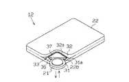
一方、図2〜図5に示すように、携帯機12は、薄型のケース22本体内に、送信回路16、受信回路17、マイクロコンピュータ(マイコン)18、アンテナ19、回路基板20、電源としての電池21、緊急用のメカキー23等を備えている。
【0018】
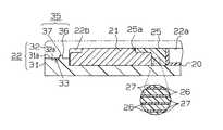
ケース本体22は、互いに対向して配置されるベース部31とカバー部32とを接着又は溶着することにより構成されている。ケース本体22の角部側面は、ベース部31とカバー部32とが接着されない箇所であって、その非接着箇所が携帯機12の電池挿脱部33となっている。電池挿脱部33は、ケース本体22の厚み方向に対して直交する方向に沿って延びる線状の開放口である。ケース本体22は、弾性変形可能な可撓性材料から形成されており、具体的には、ポリエチレン系樹脂、シリコン系樹脂、ウレタン系樹脂、ポリイミド系樹脂、オレフィン系エラストマー樹脂、スチレン系エラストマー樹脂等の樹脂材料から形成されている。
【0019】
ケース本体22内には、回路基板20を配置する回路配置部22a、ボタン状の電池21を収納する電池収納部22b、メカキー23を収納するメカキー収納部22c等が区画形成されている。回路配置部22aには、送信回路16、受信回路17、マイクロコンピュータ(マイコン)18、アンテナ19等が回路基板20に実装された状態で配置されている。回路基板20としては、柔軟性、屈曲性を備えたフレキシブルプリント基板(FPC)が用いられている。ここでいうフレキシブルプリント基板とは、ポリエステル(PET)等のフィルム上に、印刷、またはエッチング等により導体回路がパターン形成されたものである。
【0020】
回路基板20の端部には、電池21の電源を供給する電極としてのターミナル25が設けられている。ターミナル25の材料として、金属繊維26を絶縁性のシリコン樹脂27等で固めて得られた異方性導電体(信越ポリマー株式会社製「インターコネクタ」等)が用いられている。この場合、ベース部31とカバー部32とが対向して組み付けられると、異方性導電体からなるターミナル25には弾性力が作用する。そして、ターミナル25の先端25aが、電池21に対し圧接されるようになっている。この状態で、電源が電池21から回路基板20に供給されている。
【0021】
電池挿脱部33が閉じているとき、ベース部31とカバー部32とには、それらが互いに接合する接合面31a,32aを有している。前記電池挿脱部33とその内側に位置する電池収納部22bとの間において、ベース部31の接合面31aには、第1の嵌合部としての嵌合突起36が形成されている。嵌合突起36は、電池挿脱部33と電池収納部22bとを仕切るように略U字状に形成されている。また、カバー部32の接合面32aには、前記嵌合突起36と対峙するように嵌合溝37が凹設されている。電池挿脱部33が閉じている状態では、嵌合突起36と嵌合溝37とが凹凸の関係で嵌合するようになっている。この場合、電池挿脱部33には、嵌合突起36と嵌合溝37とが嵌合することによって防水構造が形成されている。
【0022】
次に、電池21の交換作業をする際の一連の動作を図2、図3に従って説明する。
まず、ベース部31とカバー部32との境界部を外側へ拡げるように、ケース本体22の角部付近を撓ませる。すると、ベース部31の嵌合突起36とカバー部32の嵌合溝37との嵌合が解除され、ケース本体22の角部側面において電池挿脱部33が開口される。このとき、電池収納部22bのみが外部に開放され、開口した電池挿脱部33を介して、同電池収納部22bから使用済みの電池21を取り出す。
【0023】
続いて、開口した電池挿脱部33を介して、新品の電池21を電池収納部22bに挿入する。次に、ベース部31とカバー部32とを互いに接近させるように、ケース本体22の角部付近を撓ませる。すると、ベース部31の嵌合突起36とカバー部32の嵌合溝37とが嵌合し、ベース部31の接合面31aとカバー部32の接合面32aとが互いに接合され、電池挿脱部33が閉じられる。このとき、電池挿脱部33には、嵌合突起36と嵌合溝37とが嵌合することにより防水構造が形成される。
【0024】
本実施形態によれば、以下のような効果を得ることができる。
(1)ケース本体22は、弾性変形可能な可撓性材料から形成されている。このため、ケース本体22の角部付近を撓ませると、電池挿脱部33が開口し、電池収納部22bのみが外部に開放される。そして、開口した電池挿脱部33を介して、電池収納部22bに電池21を無理なく挿脱することができる。よって、電池21の交換作業を無理なく行なうことができる。
【0025】
(2)携帯機12では、ケース本体22を撓ませることにより、電池挿脱部33を開口して電池21の交換作業を行なうようになっている。この構成によれば、図13に示す電池蓋57が必要なくなるため、携帯機12の携帯中に、電池蓋57が外れる等の不具合を確実に防止することができる。よって、携帯機12の防水性が悪化するのを防ぐことができる。
【0026】
(3)ケース本体22は、弾性変形可能な可撓性材料から形成されている。この場合、ケース本体22は可撓性を有するため、その形状を、外部から加えられた力に応じて撓ませることができる。このため、携帯機12の携帯中に外部から無理な力が加えられたとしても、ケース本体22は弾性変形する反面割れにくくなっている。従って、携帯機12の外部応力による壊れにくさを向上させることができる。
【0027】
(4)電池収納部22bのみを外部に開放する電池挿脱部33が、ケース本体22の角部側面に設けられている。この場合、電池収納部22bは、電池挿脱部33を介して外部に開放され易い位置に配置されているため、電池21の交換作業を容易に行なうことができる。よって、携帯機12の取り扱い易さを向上させることができる。
【0028】
(5)電池挿脱部33には、ベース部31の嵌合突起36とカバー部32の嵌合溝37とが凹凸の関係で嵌合することにより防水構造が形成される。このため、電池挿脱部33からケース本体22内に浸水するのを防止することができる。よって、携帯機12の防水性を確保することができる。
【0029】
(6)ケース本体22は、ポリエチレン系樹脂、シリコン系樹脂、ウレタン系樹脂、ポリイミド系樹脂、オレフィン系エラストマー樹脂、スチレン系エラストマー樹脂等の可撓性を有する樹脂材料から形成されている。この場合、ケース本体22は可撓性を有することから、携帯機12の外部応力に対する壊れにくさをより向上させることができる。また、ベース部31の接合面31aとカバー部32の接合面32aとを、それぞれが互いに密着するように接合させることができる。よって、電池挿脱部33では防水シーリング効果が発揮されるため、携帯機12の防水性を向上させることができる。
【0030】
(7)回路基板20はフレキシブルプリント基板からなる。このため、携帯機12の携帯中に外部から無理な力が加えられたとしても、回路基板20は弾性変形する反面割れにくくなっている。従って、携帯機12の外部応力による壊れにくさをより一層向上させることができる。
【0031】
(8)電池21の電源を回路基板20に供給するターミナル25としては、金属繊維26をシリコン樹脂27で固めて得られた異方性導電体が用いられている。この場合、ターミナル25は、その先端25aが電池21に圧接された状態で、電池21と電気的に接続されている。このため、電池21からターミナル25の先端25aを外れにくくすることができる。従って、携帯機12の信頼性を向上させることができる。
【0032】
(9)ケース本体22内には、緊急用のメカキー23が収容されている。このため、携帯機12の電圧低下が生じた場合、メカキー23を使用することにより、ドアの施解錠やエンジン始動等を行なうことができる。従って、携帯機12の利便性を向上させることができる。
[第2実施形態]
以下、本発明を車両の遠隔操作に使用される携帯機40に具体化した第2実施形態を図6〜図11に従って説明する。なお、第2実施形態の携帯機40は、第1実施形態の携帯機12を変更したのみの構成であるため、同様の部分についてはその詳細な説明は省略する。
【0033】
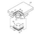
図6、図7に示すように、ケース本体22には、電池挿脱部33を閉じる状態に保持する保持手段としてのクリップ41が設けられている。クリップ41は、断面凹状に形成されており、電池挿脱部33におけるケース本体22の両面を挟み込むようにして、同ケース本体22に着脱可能に装着されている。クリップ41は、金属や樹脂等の硬質な材料から形成されている。
【0034】
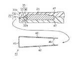
図8、図9は図6のY−Y断面図を示し、図10、図11は図6のZ−Z断面図を示している。ケース本体22は、クリップ41が装着される部分が、他の部分と比べ、クリップ41の厚み分だけ肉薄に形成されている。このため、クリップ41がケース本体22に装着された状態では、クリップ41の表面とケース本体22の表面とが面一に配置されるようになっている。また、クリップ41が装着された状態では、電池21とターミナル25との接触部に同クリップ41の先端部が位置している。このとき、装着されたクリップ41によって、電池21とターミナル25との接触圧が高められている。
【0035】
クリップ41は、L字状の基部43と、その基部43の両端から間隔をおいて対峙するように形成された2つの挟み込み部42とから構成されている。両挟み込み部42の間隔は、基部43から遠ざかるに従い狭くなるように設定されている。クリップ41は、基部43を支点として、両挟み込み部42が撓むようになっている。
【0036】
本実施形態では、クリップ41が図7に示すA方向から装着される場合について説明する。図7〜図9に示すように、クリップ41における両挟み込み部42の内面には、同クリップ41の着脱方向に沿って延びるガイド突起44が形成されている。一方、ケース本体22の角部における表裏両面には、前記ガイド突起44と対峙するガイド溝45が凹設されている。クリップ41をA方向からケース本体22に装着するとき、クリップ41のガイド突起44が、ケース本体22のガイド溝45に係入されるようになっている。
【0037】
図7、図10、図11に示すように、クリップ41における両挟み込み部42の内面には、前記ガイド突起44と直交する方向に沿って延びる抜止突起46が形成されている。一方、ケース本体22の角部における表裏両面には、クリップ41の抜止突起46と対峙する係合凹部47が凹設されている。ケース本体22にクリップ41の装着が完了したとき、クリップ41の抜止突起46とケース本体22の係合凹部47とが互いに係合されるようになっている。
【0038】
次に、クリップ41を装着する際の一連の動作を図7〜図11に従って説明する。
クリップ41が装着される際、両挟み込み部42のガイド突起44が、ケース本体22のガイド溝45に係入される。すると、クリップ41は、ガイド溝45に沿ってA方向からケース本体22に装着される。このとき、クリップ41は、両挟み込み部42の内面をケース本体22の表裏両面に摺接させながら装着される。そして、クリップ41の装着が完了したとき、両挟み込み部42の抜止突起46が、ケース本体22の係合凹部47に係合される。このとき、両挟み込み部42の内面が、ケース本体22の角部における表裏両面に対し圧接されている。
【0039】
一方、クリップ41を取り外す際、クリップ41の抜止突起46とケース本体22の係合凹部47との係合を解除する。そして、クリップ41をガイド溝45に沿わせながらケース本体22から取り外す。本実施形態では、電池21の交換作業を行なう際、クリップ41をケース本体22から取り外した後に、前記第1実施形態で示す一連の動作が行なわれる。
【0040】
本実施形態によれば、以下のような効果を得ることができる。
(10)クリップ41は、電池挿脱部33におけるケース本体22の両面を挟み込むようにして装着されている。この場合、クリップ41を装着することにより、ベース部31の接合面31aとカバー部32の接合面32aとが強く接合されるため、電池挿脱部33を閉じることができる。このため、電池挿脱部33からケース本体22内に浸水するのを防止することができる。よって、携帯機12の防水性を向上させることができる。
【0041】
(11)クリップ41は、電池挿脱部33におけるケース本体22の両面を挟み込むようにして装着されている。この場合、クリップ41を装着することにより、電池収納部22bに配置された電池21と、同電池21の電源を回路基板20に供給するターミナル25との接触圧を高めることができる。よって、電池21からターミナル25が外れにくくなることから、携帯機12の信頼性を向上させることができる。
【0042】
(12)クリップ41は、金属や樹脂等の硬質な材料から形成されている。この場合、クリップ41を装着することにより、電池挿脱部33において、ベース部31の接合面31aとカバー部32の接合面32aとがより強い力で接合される。このため、電池挿脱部33が閉じられるとともに、電池21とターミナル25との接触圧をより高めることができる。よって、携帯機12の防水性及び信頼性をより一層向上させることができる。
【0043】
(13)ケース本体22を厚み方向から透影してみた場合に、クリップ41は、電池収納部22bとほぼ同等の面積を有している。このため、クリップ41が金属からなる場合、電波の遮蔽が極力抑えられるため、携帯機12の通信機能が低下するのを防ぐことができる。
【0044】
(14)クリップ41は、両挟み込み部42の間隔が、基部43から遠ざかるに従い狭くなるように設定されている。このため、クリップ41を装着することにより、同クリップ41の両挟み込み部42がケース本体22の表裏両面に対し圧接される。よって、電池挿脱部33の両接合面31a,32a同士をより一層強い力で接合させることができる。
【0045】
(15)クリップ41にはその着脱方向に沿ってガイド突起44が形成されるとともに、ケース本体22の表裏両面には前記ガイド突起44と対峙する位置にガイド溝45が形成されている。このため、クリップ41をケース本体22に装着するとき、クリップ41のガイド突起44がケース本体22のガイド溝45に係入されるようになっている。よって、ケース本体22にクリップ41を装着し易くすることができる。
【0046】
(16)クリップ41をケース本体22に装着完了したとき、クリップ41の抜止突起46とケース本体22の係合凹部47とが互いに係合されるようになっている。よって、クリップ41をケース本体22から外れにくくすることができる。
【0047】
(17)クリップ41がケース本体22に装着されているとき、同クリップ41の表面とケース本体22の表面とが面一になるように配置されている。この場合、携帯機12の表面には凹凸が少なくなるため、衣服の布地等に携帯機12が引っ掛かりにくくなる。このため、携帯機12は、衣服のポケットや財布等に入れて携帯し易くなっている。よって、携帯機12の携帯性を向上させることができる。
【0048】
なお、前記第1実施形態及び前記第2実施形態は以下のように変更してもよい。
・前記第1実施形態及び前記第2実施形態において、携帯機12を用いる遠隔操作は、車両のスマートエントリ機能やスマートイグニッション機能に具体化されていた。しかし、この遠隔操作装置は、例えば、携帯機を用いた住宅のドア錠の施解錠や、携帯電話を利用した家電機器やパソコン等の遠隔操作等に具体化することも可能である。
【0049】
・前記第1実施形態及び前記第2実施形態において、ケース本体22は、ベース部31とカバー部32とを接着または溶着することによって形成されていた。しかし、これ以外の方法でケース本体22を形成してもよく、例えば、ポッティングやキャスティング等のように、熱硬化性の樹脂を型の中に流し込み、硬化させる注型加工法を用いることにより、ベース部31とカバー部32とを一体的に形成することもできる。
【0050】
・前記第1実施形態及び前記第2実施形態において、電池収納部22bのみを外部に開放する電池挿脱部33は、ケース本体22の角部に設けられていた。しかし、この電池挿脱部33は、電池収納部22bの場所に応じて、ケース本体22の任意の箇所に設けることができる。
【0051】
・前記第1実施形態及び前記第2実施形態において、電池挿脱部33には、ベース部31に形成された嵌合突起36と、カバー部32に形成された嵌合溝37とからなる防水構造が形成されていた。しかし、カバー部32に嵌合突起36を形成し、ベース部31に嵌合溝37を形成しても差し支えない。
【0052】
・前記第1実施形態及び前記第2実施形態において、嵌合突起36と嵌合溝37とからなる防水構造は、電池挿脱部33と電池収納部22bとを仕切るように略U字状に形成されていた。しかし、この防水構造は、電池収納部22bの全周を包囲するように円環状に形成してもよい。
【0053】
・前記第1実施形態及び前記第2実施形態において、電池21の電源を回路基板20に供給するターミナル25は、金属繊維26をシリコン樹脂27で固めて得られる異方性導電体が用いられていた。しかし、この異方性導電体からなるターミナル25に替えて、金属製のターミナル25を使用することもできる。
【0054】
・前記第2実施形態において、図7に示すA方向以外に、B方向からクリップ41を装着することも可能である。この場合、クリップ41において、ガイド突起44が抜止突起46として機能するとともに、抜止突起46がガイド突起44として機能する。また、ケース本体22において、ガイド溝45が係合凹部47として機能するとともに、係合凹部47がガイド溝45として機能する。
【0055】
次に、上記実施形態及び別例によって把握される技術的思想を以下に記載する。
(1)前記ケース本体は、ポリエチレン系樹脂、シリコン系樹脂、ウレタン系樹脂、ポリイミド系樹脂、オレフィン系エラストマー樹脂、スチレン系エラストマー樹脂等から選ばれた少なくとも一種の樹脂材料から形成されていることを特徴とする請求項1〜5のうちいずれか1項に記載の携帯機。
【0056】
(2)前記ケース本体内に収容された回路基板はフレキシブルプリント基板であることを特徴とする請求項1〜5のうちいずれか1項又は技術的思想(1)に記載の携帯機。
【0057】
(3)前記電池の電源を前記回路基板に供給する電極は、金属繊維を樹脂で固めて得られた異方性導電体からなることを特徴とする技術的思想(2)に記載の携帯機。
【0058】
(4)前記ケース本体内には、機械的にドア錠の施解錠を行なうメカキーが収容されていることを特徴とする請求項1〜5のうちいずれか1項又は技術的思想(1)〜(3)のうちいずれか1項に記載の携帯機。
【0059】
(5)前記保持手段は、前記ケース本体を厚み方向から見たとき、同ケース本体に形成された電池収納部とほぼ同じ面積を有していることを特徴とする請求項4又は5に記載の携帯機。
【0060】
(6)前記保持手段は、基部と、その基部の両端から間隔をおいて対峙するように突設された2つの挟み込み部とから構成され、前記両挟み込み部の間隔は前記基部から遠ざかるに従い狭くなるように設定されていることを特徴とする請求項4又は5及び技術的思想(5)に記載の携帯機。
【0061】
(7)前記保持手段と前記ケース本体とが互いに接する面のうちいずれか一方には、同保持手段の着脱方向に沿って延びるガイド突起が形成され、他方には前記保持手段の着脱方向に沿って延びるガイド溝が形成され、前記保持手段が前記ケース本体に着脱されるときに、前記ガイド溝に前記ガイド突起が係入されることを特徴とする請求項4又は5及び技術的思想(5)又は(6)に記載の携帯機。
【0062】
(8)前記保持手段と前記ケース本体とが互いに接する面のうちいずれか一方には、抜止突起が設けられ、他方には前記抜止突起と着脱可能な係止凹部が設けられ、前記保持手段が装着されるときに前記抜止突起と前記係合凹部とが互いに係合されることを特徴とする請求項4又は5及び技術的思想(5)〜(7)のうちいずれか1項に記載の携帯機。
【0063】
【発明の効果】
以上詳述したように、本発明によれば、携帯機の防水性を確保できるとともに、外部応力に対する壊れにくさを向上させることができる。
【図面の簡単な説明】
【図1】第1実施形態における遠隔操作装置の概念図。
【図2】同じく電池挿脱部が閉じている状態での携帯機の斜視図。
【図3】同じく電池挿脱部が開口している状態での携帯機の斜視図。
【図4】同じく携帯機の断面図。
【図5】同4のA−A断面図。
【図6】第2実施形態における電池挿脱部が閉じている状態での携帯機の斜視図。
【図7】同じく電池挿脱部が開口している状態での携帯機と保持手段の斜視図。
【図8】図6のY−Y部分断面図。
【図9】同じくクリップを外した状態での携帯機の部分断面図とクリップの断面図。
【図10】図6のZ−Z部分断面図。
【図11】同じくクリップを外した状態での携帯機の部分断面図とクリップの断面図。
【図12】従来の携帯機の断面図。
【図13】従来の携帯機の斜視図。
【符号の説明】
12,40…携帯機、21…電池、22…ケース本体、22b…電池収納部、31…ベース部、31a…接合面、32…カバー部、32a…接合面、33…電池挿脱部、36…嵌合突起(第1の嵌合部)、37…嵌合溝(第2の嵌合部)、41…クリップ(保持手段)。[0001]
BACKGROUND OF THE INVENTION
The present invention relates to a portable device used for a remote control operation of a vehicle or the like.
[0002]
[Prior art]
In recent years, remote control operations using portable devices have been used in various fields against the background of the development of information communication technology and the popularization of communication devices. The remote operation device is composed of a portable device operated by a user (owner) and a transmission / reception device mounted on an external device to be operated. Specifically, the remote operation device is a remote home appliance using a mobile phone. Operation and remote operation of a vehicle using an electronic key are known. (For example, refer to Patent Document 1.)
As shown in FIG. 12, in a
[0003]
[Patent Document 1]
JP 2001-146315 A
[0004]
[Problems to be solved by the invention]
However, as the
[0005]
The present invention has been made in view of the above problems, and an object of the present invention is to provide a portable device capable of ensuring waterproofness and improving the resistance to breakage against external stress.
[0006]
[Means for Solving the Problems]
In order to achieve the above object, the invention according to claim 1 allows the case main body to be used in a portable device that performs predetermined communication with an external device using a battery disposed in a battery housing portion in the case main body as a power source. Formed by flexible material,Partitioning the battery housing in the case body, The battery housing portion is bent by bending the case body.only Is provided with a battery insertion / removal portion that can be opened to the outside in the case body.
[0007]
According to this configuration, when the case body is bent, the battery insertion / removal portion opens and the battery storage portiononly Is open to the outside. Then, the battery can be inserted / removed without difficulty in the battery storage part via the opened battery insertion / removal part. Therefore, the battery replacement operation can be performed without difficulty. In addition, since the battery lid is not required, problems such as the battery lid coming off are reliably prevented. Therefore, it can prevent that the waterproofness of a portable device deteriorates. Furthermore, since the case main body has flexibility, the shape can be bent according to the force applied from the outside. For this reason, a case main body becomes difficult to crack with respect to external stress. Therefore, it is possible to improve the resistance to breakage due to external stress of the portable device.
[0008]
The gist of the invention described in claim 2 is that, in the invention described in claim 1, the battery insertion / removal portion is provided on a side surface of the corner portion of the case body.
According to this configuration, the battery storage portion is provided at a position that is easily opened to the outside. For this reason, the battery replacement operation can be easily performed. Therefore, the handling ease of the portable device can be improved.
[0009]
The invention according to claim 3 is the invention according to claim 1 or 2, wherein the battery insertion / removal portion is a linear opening extending along a direction orthogonal to the thickness direction of the case main body. In addition, a first fitting portion is provided on one of the joint surfaces that are joined to each other when the battery insertion / removal portion is closed so as to partition the battery insertion / removal portion and the battery storage portion. On the other hand, a second fitting portion is provided opposite to the first fitting portion, and the first fitting portion and the second fitting portion are in a state where the battery insertion / removal portion is closed. The gist of this is that they are fitted in an uneven relationship.
[0010]
According to this configuration, since the first fitting portion and the second fitting portion are fitted in a concavo-convex relationship, the battery insertion / removal portion is difficult to open, and the waterproofness of the portable device can be ensured. it can. The invention according to claim 4 is the invention according to any one of claims 1 to 3, wherein the case body is provided with holding means for holding the battery insertion / removal portion in a closed state. This is the gist.
[0011]
According to this structure, since both the joint surfaces in a battery insertion / removal part are strongly joined by a holding means, the waterproofness of a portable machine can be improved.
According to a fifth aspect of the present invention, in the invention of the fourth aspect, the holding means is formed in a concave shape in cross section, and with respect to the case body so as to sandwich both surfaces of the case body in the battery insertion / removal portion. Its gist is to be detachably mounted.
[0012]
According to this configuration, since the holding means is formed in a concave shape in cross section, it is pushed in and attached so as to sandwich the case main body. When replacing the battery, it can be removed from the case body by pulling out the holding means as it is. Therefore, the holding means can be easily attached and detached.
[0013]
DETAILED DESCRIPTION OF THE INVENTION
[First Embodiment]
Hereinafter, an embodiment embodying the present invention will be described in detail with reference to FIGS.
[0014]
As a remote operation of the vehicle, a smart entry function that automatically unlocks the door lock when the user (owner) approaches the vehicle by ID verification and automatically locks the door lock when leaving the vehicle. In addition, a smart ignition function that makes the engine startable has been proposed.
[0015]
As shown in FIG. 1, the vehicle
[0016]
For example, in the smart ignition device, an ID request signal is transmitted from the transmission /
[0017]
On the other hand, as shown in FIGS. 2 to 5, the
[0018]
The case
[0019]
In the case
[0020]
At the end of the
[0021]
When the battery insertion /
[0022]
Next, a series of operations when replacing the
First, the vicinity of the corner portion of the
[0023]
Subsequently, the
[0024]
According to this embodiment, the following effects can be obtained.
(1) The
[0025]
(2) In the
[0026]
(3) The
[0027]
(4)
[0028]
(5) The battery insertion /
[0029]
(6) The
[0030]
(7) The
[0031]
(8) As the terminal 25 for supplying the power of the
[0032]
(9) An emergency mechanical key 23 is accommodated in the
[Second Embodiment]
Hereinafter, a second embodiment in which the present invention is embodied in a
[0033]
As shown in FIGS. 6 and 7, the case
[0034]
8 and 9 show the YY sectional view of FIG. 6, and FIGS. 10 and 11 show the ZZ sectional view of FIG. The
[0035]
The
[0036]
In the present embodiment, a case where the
[0037]
As shown in FIGS. 7, 10, and 11, a retaining
[0038]
Next, a series of operations when mounting the
When the
[0039]
On the other hand, when the
[0040]
According to this embodiment, the following effects can be obtained.
(10) The
[0041]
(11) The
[0042]
(12) The
[0043]
(13) When the case
[0044]
(14) The
[0045]
(15)
[0046]
(16) When the
[0047]
(17) When the
[0048]
In addition, you may change the said 1st Embodiment and the said 2nd Embodiment as follows.
In the first embodiment and the second embodiment, the remote operation using the
[0049]
In the first embodiment and the second embodiment, the case
[0050]
In the first embodiment and the second embodiment, the
[0051]
In the first embodiment and the second embodiment, the battery insertion /
[0052]
-In the said 1st Embodiment and the said 2nd Embodiment, the waterproof structure which consists of the
[0053]
-In the said 1st Embodiment and the said 2nd Embodiment, the terminal 25 which supplies the power supply of the
[0054]
In the second embodiment, the
[0055]
Next, the technical idea grasped by the above embodiment and another example will be described below.
(1) The case body is formed of at least one resin material selected from polyethylene resin, silicon resin, urethane resin, polyimide resin, olefin elastomer resin, styrene elastomer resin, and the like. The portable device according to any one of claims 1 to 5.
[0056]
(2) The portable device according to any one of claims 1 to 5, or the technical idea (1), wherein the circuit board accommodated in the case body is a flexible printed board.
[0057]
(3) The portable device according to the technical idea (2), wherein the electrode for supplying the power of the battery to the circuit board is made of an anisotropic conductor obtained by solidifying a metal fiber with a resin. .
[0058]
(4) A mechanical key that mechanically locks and unlocks the door lock is accommodated in the case main body, or any one of the technical ideas (1) to (5). The portable device according to any one of (3).
[0059]
(5) The holding means has substantially the same area as a battery housing portion formed in the case body when the case body is viewed from the thickness direction. Portable machine.
[0060]
(6) The holding means includes a base portion and two sandwiching portions projecting so as to face each other with an interval from both ends of the base portion, and the spacing between both sandwiching portions becomes narrower as the distance from the base portion increases. The portable device according to claim 4 or 5 and the technical idea (5), wherein the portable device is set to be
[0061]
(7) A guide protrusion extending along the attaching / detaching direction of the holding means is formed on any one of the surfaces where the holding means and the case main body contact each other, and the other along the attaching / detaching direction of the holding means. The guide protrusion is engaged with the guide groove when the holding means is attached to and detached from the case body, and the technical idea (5). ) Or the portable device according to (6).
[0062]
(8) A retaining protrusion is provided on one of the surfaces where the holding means and the case main body are in contact with each other, and the other is a locking recess that is detachable from the retaining protrusion.Part Provided, saidHolding means 6. The device according to claim 4, wherein the retaining protrusion and the engagement recess are engaged with each other when the device is mounted. 7. Portable machine.
[0063]
【The invention's effect】
As described above in detail, according to the present invention, the waterproof property of the portable device can be ensured and the resistance to breakage against external stress can be improved.
[Brief description of the drawings]
FIG. 1 is a conceptual diagram of a remote control device according to a first embodiment.
FIG. 2 is a perspective view of the portable device in a state where the battery insertion / removal unit is also closed.
FIG. 3 is a perspective view of the portable device with the battery insertion / removal part opened.
FIG. 4 is a cross-sectional view of the portable device.
FIG. 5 is a sectional view taken along line AA in FIG.
FIG. 6 is a perspective view of a portable device in a state where a battery insertion / removal unit is closed in the second embodiment.
FIG. 7 is a perspective view of the portable device and the holding means in a state where the battery insertion / removal portion is also open.
8 is a YY partial cross-sectional view of FIG. 6;
FIG. 9 is a partial sectional view of the portable device and a sectional view of the clip with the clip removed.
10 is a partial sectional view taken along the line ZZ in FIG. 6;
FIG. 11 is a partial cross-sectional view of the portable device and a cross-sectional view of the clip with the clip removed.
FIG. 12 is a cross-sectional view of a conventional portable device.
FIG. 13 is a perspective view of a conventional portable device.
[Explanation of symbols]
12, 40 DESCRIPTION OF SYMBOLS ... Portable machine, 21 ... Battery, 22 ... Case main body, 22b ... Battery storage part, 31 ... Base part, 31a ... Joining surface, 32 ... Cover part, 32a ... Joining surface, 33 ... Battery insertion / removal part, 36 ... Fitting Projection (first fitting portion), 37... Fitting groove (second fitting portion), 41... Clip (holding means).
Claims (5)
Translated fromJapanese前記ケース本体を可撓性材料によって形成し、同ケース本体に前記電池収納部を区画形成し、前記ケース本体を撓ませることで前記電池収納部のみが外部に開放可能な電池挿脱部を同ケース本体に設けたことを特徴とする携帯機。In a portable device that performs a predetermined communication with an external device using a battery arranged in a battery storage portion in the case body as a power source,
The case body is formed by flexible material,the battery housing portion is partitioned and formed in the case main body,only said battery housing portion by deflecting the case body is a battery insertion and removal portion openable to the outside the A portable device characterized by being provided in a case body.
Priority Applications (5)
| Application Number | Priority Date | Filing Date | Title |
|---|---|---|---|
| JP2003026919AJP4057437B2 (en) | 2003-02-04 | 2003-02-04 | Portable machine |
| US10/766,799US7505279B2 (en) | 2003-02-04 | 2004-01-28 | Portable device having flexible case |
| DE200460000052DE602004000052T2 (en) | 2003-02-04 | 2004-01-29 | Portable device with flexible housing |
| EP20040001961EP1445738B1 (en) | 2003-02-04 | 2004-01-29 | Portable device having flexible case |
| KR20040006644AKR100953597B1 (en) | 2003-02-04 | 2004-02-02 | Mobile phone with flexible case |
Applications Claiming Priority (1)
| Application Number | Priority Date | Filing Date | Title |
|---|---|---|---|
| JP2003026919AJP4057437B2 (en) | 2003-02-04 | 2003-02-04 | Portable machine |
Publications (2)
| Publication Number | Publication Date |
|---|---|
| JP2004241896A JP2004241896A (en) | 2004-08-26 |
| JP4057437B2true JP4057437B2 (en) | 2008-03-05 |
Family
ID=32652965
Family Applications (1)
| Application Number | Title | Priority Date | Filing Date |
|---|---|---|---|
| JP2003026919AExpired - Fee RelatedJP4057437B2 (en) | 2003-02-04 | 2003-02-04 | Portable machine |
Country Status (5)
| Country | Link |
|---|---|
| US (1) | US7505279B2 (en) |
| EP (1) | EP1445738B1 (en) |
| JP (1) | JP4057437B2 (en) |
| KR (1) | KR100953597B1 (en) |
| DE (1) | DE602004000052T2 (en) |
Families Citing this family (30)
| Publication number | Priority date | Publication date | Assignee | Title |
|---|---|---|---|---|
| JP4548205B2 (en)* | 2005-04-27 | 2010-09-22 | 株式会社デンソー | Wireless transceiver and manufacturing method thereof |
| JP4548206B2 (en)* | 2005-04-27 | 2010-09-22 | 株式会社デンソー | Wireless transceiver and manufacturing method thereof |
| JP2007258877A (en)* | 2006-03-22 | 2007-10-04 | Tokai Rika Co Ltd | Portable machine |
| US20080055824A1 (en)* | 2006-08-25 | 2008-03-06 | Innovatier, Inc. | Battery powered device having a protective frame |
| DE102007004567A1 (en)* | 2007-01-30 | 2008-07-31 | Robert Bosch Gmbh | Electrochemical cell e.g. coffee-bag cell, housing device for traction system of e.g. hybrid motor vehicle, has cell and lugs for contacting, where cell is enclosed between housing parts, which clamp cell between parts using pressing force |
| JP5099624B2 (en)* | 2007-05-21 | 2012-12-19 | Necカシオモバイルコミュニケーションズ株式会社 | Battery holding device and portable electronic device equipped with the same |
| USD624077S1 (en)* | 2007-09-14 | 2010-09-21 | Mitsubishi Heavy Industries, Ltd | Electronic toll collection machine |
| JP5206534B2 (en)* | 2009-03-25 | 2013-06-12 | 株式会社デンソー | Electronic key |
| JP5163776B2 (en) | 2010-07-13 | 2013-03-13 | 株式会社デンソー | Card key |
| USD669079S1 (en)* | 2010-09-01 | 2012-10-16 | Innovative Timing Systems | RFID tag reader housing |
| JP5551561B2 (en)* | 2010-10-08 | 2014-07-16 | 株式会社サージュ | card reader |
| FR2967188B1 (en)* | 2010-11-05 | 2013-05-31 | Valeo Securite Habitacle | RETRACTABLE INSERT KEY AND ASSOCIATED INSERT DEPLOYMENT MODULE |
| JP5954095B2 (en)* | 2012-10-09 | 2016-07-20 | 株式会社デンソー | Card key |
| US9270795B2 (en)* | 2012-12-18 | 2016-02-23 | Panasonic Intellectual Property Management Co., Ltd. | Communication antenna unit and mobile terminal apparatus |
| GB201306369D0 (en)* | 2013-04-09 | 2013-05-22 | Photocure As | Irradiation device |
| US9185275B2 (en)* | 2013-07-09 | 2015-11-10 | Lenovo (Singapore) Pte. Ltd. | Control flap |
| US9363264B2 (en)* | 2013-11-25 | 2016-06-07 | At&T Intellectual Property I, L.P. | Networked device access control |
| US9175837B1 (en) | 2014-10-16 | 2015-11-03 | Arcachon Holdings Llc | Marker system |
| US9746561B2 (en) | 2014-10-16 | 2017-08-29 | Arcachon Holdings Llc | Marker system |
| US9144261B2 (en) | 2014-10-16 | 2015-09-29 | Arcachon Holdings Llc | Combination marker light and infrared interrogation device |
| US9341714B2 (en) | 2014-10-16 | 2016-05-17 | Arcachon Holdings Llc | Marker system |
| JP6315276B2 (en)* | 2014-11-19 | 2018-04-25 | 株式会社デンソー | Portable machine |
| USD773406S1 (en)* | 2015-02-03 | 2016-12-06 | Lg Electronics Inc. | Smart key for automobiles |
| US11049379B2 (en) | 2015-05-18 | 2021-06-29 | Arcachon Holdings Llc | Marker system with zone notification |
| US11771164B2 (en) | 2015-05-18 | 2023-10-03 | Arcachon Holdings Llc | System, method, and apparatus for synchronizing local flashing in a marker system |
| US10897805B2 (en) | 2015-05-18 | 2021-01-19 | Arcachon Holdings Llc | System, method, and apparatus for synchronizing flashing in a marker system |
| US11047984B2 (en) | 2015-05-18 | 2021-06-29 | Arcachon Holdings Llc | System, method, and apparatus for synchronizing local flashing in a marker system |
| USD838022S1 (en) | 2017-06-24 | 2019-01-08 | Arcachon Holdings Llc | Marker system |
| CN111809970A (en)* | 2020-06-23 | 2020-10-23 | 孔瑞扬 | Intelligent household door lock |
| US11139130B1 (en) | 2021-02-09 | 2021-10-05 | Arcachon Holdings Llc | Safety switch |
Family Cites Families (13)
| Publication number | Priority date | Publication date | Assignee | Title |
|---|---|---|---|---|
| US4121160A (en)* | 1977-03-22 | 1978-10-17 | Cataldo Thomas R | Switch means for radio alarm device |
| JPS6149388A (en) | 1984-08-15 | 1986-03-11 | 株式会社日立製作所 | Device for connecting battery |
| CH665059A5 (en)* | 1985-04-03 | 1988-04-15 | Rdi Limited Partnership | ASSEMBLY INCLUDING A MODULAR ELECTRICAL OR ELECTRONIC CIRCUIT AND A CONNECTOR FOR CONNECTING THE CIRCUIT TO A SELF - CONTAINED ELECTRICAL SYSTEM. |
| JPS6238035A (en)* | 1985-08-12 | 1987-02-19 | Nissan Motor Co Ltd | Thin type portable device |
| WO1996028629A1 (en)* | 1995-03-16 | 1996-09-19 | Medeco Security Locks, Inc. | Universal apparatus for use with electronic and/or mechanical access control devices |
| DE19802300B4 (en) | 1997-01-30 | 2008-02-07 | Marquardt Gmbh | Case for electronic key |
| DE19718453C1 (en) | 1997-04-30 | 1998-09-03 | Siemens Ag | Circuit board plastics housing, used for remote control or car key |
| US6193069B1 (en)* | 1999-04-22 | 2001-02-27 | Compaq Computer Corporation | Apparatus for packaging processing system elements for mailing and shipping |
| JP2001200664A (en) | 2000-01-17 | 2001-07-27 | Alps Electric Co Ltd | Portable unit for keyless entry device |
| JP3811609B2 (en)* | 2000-10-02 | 2006-08-23 | アルプス電気株式会社 | Button type battery storage device |
| JP2002339605A (en) | 2001-05-16 | 2002-11-27 | Tokai Rika Co Ltd | Portable apparatus for remote control |
| US6674639B2 (en)* | 2001-09-06 | 2004-01-06 | High Tech Computer, Corp. | Protective cover with ternary structure |
| US6897371B1 (en)* | 2002-08-27 | 2005-05-24 | A K Stamping Co. Inc. | One-piece shielding enclosure with selective interior access, and method and blank therefor |
- 2003
- 2003-02-04JPJP2003026919Apatent/JP4057437B2/ennot_activeExpired - Fee Related
- 2004
- 2004-01-28USUS10/766,799patent/US7505279B2/ennot_activeExpired - Fee Related
- 2004-01-29DEDE200460000052patent/DE602004000052T2/ennot_activeExpired - Fee Related
- 2004-01-29EPEP20040001961patent/EP1445738B1/ennot_activeExpired - Lifetime
- 2004-02-02KRKR20040006644Apatent/KR100953597B1/ennot_activeExpired - Fee Related
Also Published As
| Publication number | Publication date |
|---|---|
| EP1445738B1 (en) | 2005-08-17 |
| US7505279B2 (en) | 2009-03-17 |
| KR100953597B1 (en) | 2010-04-21 |
| KR20040071610A (en) | 2004-08-12 |
| JP2004241896A (en) | 2004-08-26 |
| EP1445738A1 (en) | 2004-08-11 |
| DE602004000052D1 (en) | 2005-09-22 |
| DE602004000052T2 (en) | 2006-05-24 |
| US20040185798A1 (en) | 2004-09-23 |
Similar Documents
| Publication | Publication Date | Title |
|---|---|---|
| JP4057437B2 (en) | Portable machine | |
| JP4464053B2 (en) | Portable machine | |
| EP2642728B1 (en) | Apparatus for waterproofing battery cover in a portable terminal | |
| KR100910684B1 (en) | Portable device for electronic key system | |
| CN106128827B (en) | Side key structure and mobile terminal | |
| JP2005120792A (en) | Door opening and closing device | |
| KR20220029280A (en) | A vehicle card key equipped with battery and a method manufacturing it | |
| US9443182B2 (en) | Card key | |
| JP5513346B2 (en) | Cover for mobile phone | |
| JP2007028206A (en) | Communication adapter | |
| JP4946587B2 (en) | Portable machine | |
| JP2008019602A (en) | Card type portable machine | |
| JP2013106196A (en) | Portable terminal | |
| JP2010219590A (en) | Remote control portable device | |
| JP5563772B2 (en) | Key head cover | |
| US20190270430A1 (en) | Electronic key | |
| CN214996868U (en) | Door handle device | |
| KR102544570B1 (en) | Portable electronic communication devices for vehicles | |
| JP3338576B2 (en) | Keyless entry system transmitter | |
| JP2008223376A (en) | Portable machine | |
| JP2009057800A (en) | Portable machine of electronic key system | |
| US20240340036A1 (en) | Mobile phone case having electronic key | |
| JPH01106658A (en) | electrical equipment | |
| KR200485965Y1 (en) | Card Key for Vehicle | |
| KR20210096516A (en) | Smartkey for vehicle |
Legal Events
| Date | Code | Title | Description |
|---|---|---|---|
| A621 | Written request for application examination | Free format text:JAPANESE INTERMEDIATE CODE: A621 Effective date:20050805 | |
| A977 | Report on retrieval | Free format text:JAPANESE INTERMEDIATE CODE: A971007 Effective date:20070806 | |
| A131 | Notification of reasons for refusal | Free format text:JAPANESE INTERMEDIATE CODE: A131 Effective date:20070821 | |
| A521 | Request for written amendment filed | Free format text:JAPANESE INTERMEDIATE CODE: A523 Effective date:20071012 | |
| TRDD | Decision of grant or rejection written | ||
| A01 | Written decision to grant a patent or to grant a registration (utility model) | Free format text:JAPANESE INTERMEDIATE CODE: A01 Effective date:20071204 | |
| A61 | First payment of annual fees (during grant procedure) | Free format text:JAPANESE INTERMEDIATE CODE: A61 Effective date:20071213 | |
| R150 | Certificate of patent or registration of utility model | Free format text:JAPANESE INTERMEDIATE CODE: R150 | |
| FPAY | Renewal fee payment (event date is renewal date of database) | Free format text:PAYMENT UNTIL: 20101221 Year of fee payment:3 | |
| LAPS | Cancellation because of no payment of annual fees |