JP4057427B2 - Lumber support device - Google Patents
Lumber support deviceDownload PDFInfo
- Publication number
- JP4057427B2 JP4057427B2JP2002580837AJP2002580837AJP4057427B2JP 4057427 B2JP4057427 B2JP 4057427B2JP 2002580837 AJP2002580837 AJP 2002580837AJP 2002580837 AJP2002580837 AJP 2002580837AJP 4057427 B2JP4057427 B2JP 4057427B2
- Authority
- JP
- Japan
- Prior art keywords
- support device
- lumbar support
- bracket
- spring
- lever
- Prior art date
- Legal status (The legal status is an assumption and is not a legal conclusion. Google has not performed a legal analysis and makes no representation as to the accuracy of the status listed.)
- Expired - Fee Related
Links
- 238000005452bendingMethods0.000claimsdescription46
- 230000008859changeEffects0.000claimsdescription6
- 230000004044responseEffects0.000claimsdescription2
- 230000008878couplingEffects0.000claims1
- 238000010168coupling processMethods0.000claims1
- 238000005859coupling reactionMethods0.000claims1
- 238000000034methodMethods0.000description10
- 230000004048modificationEffects0.000description4
- 238000012986modificationMethods0.000description4
- 230000000712assemblyEffects0.000description3
- 238000000429assemblyMethods0.000description3
- 230000000694effectsEffects0.000description3
- 239000004677NylonSubstances0.000description1
- 239000002131composite materialSubstances0.000description1
- 239000011521glassSubstances0.000description1
- 239000000463materialSubstances0.000description1
- 239000002184metalSubstances0.000description1
- 238000000465mouldingMethods0.000description1
- 229920001778nylonPolymers0.000description1
- 230000002093peripheral effectEffects0.000description1
- 230000009466transformationEffects0.000description1
- 238000003466weldingMethods0.000description1
Images


Classifications
- A—HUMAN NECESSITIES
- A61—MEDICAL OR VETERINARY SCIENCE; HYGIENE
- A61F—FILTERS IMPLANTABLE INTO BLOOD VESSELS; PROSTHESES; DEVICES PROVIDING PATENCY TO, OR PREVENTING COLLAPSING OF, TUBULAR STRUCTURES OF THE BODY, e.g. STENTS; ORTHOPAEDIC, NURSING OR CONTRACEPTIVE DEVICES; FOMENTATION; TREATMENT OR PROTECTION OF EYES OR EARS; BANDAGES, DRESSINGS OR ABSORBENT PADS; FIRST-AID KITS
- A61F5/00—Orthopaedic methods or devices for non-surgical treatment of bones or joints; Nursing devices ; Anti-rape devices
- A61F5/01—Orthopaedic devices, e.g. long-term immobilising or pressure directing devices for treating broken or deformed bones such as splints, casts or braces
- A—HUMAN NECESSITIES
- A47—FURNITURE; DOMESTIC ARTICLES OR APPLIANCES; COFFEE MILLS; SPICE MILLS; SUCTION CLEANERS IN GENERAL
- A47C—CHAIRS; SOFAS; BEDS
- A47C7/00—Parts, details, or accessories of chairs or stools
- A47C7/36—Supports for the head or the back
- A47C7/40—Supports for the head or the back for the back
- A47C7/46—Supports for the head or the back for the back with special, e.g. adjustable, lumbar region support profile; "Ackerblom" profile chairs
- A47C7/462—Supports for the head or the back for the back with special, e.g. adjustable, lumbar region support profile; "Ackerblom" profile chairs adjustable by mechanical means
- A47C7/465—Supports for the head or the back for the back with special, e.g. adjustable, lumbar region support profile; "Ackerblom" profile chairs adjustable by mechanical means by pulling an elastic cable
Landscapes
- Engineering & Computer Science (AREA)
- Health & Medical Sciences (AREA)
- Mechanical Engineering (AREA)
- Life Sciences & Earth Sciences (AREA)
- General Health & Medical Sciences (AREA)
- Biomedical Technology (AREA)
- Heart & Thoracic Surgery (AREA)
- Vascular Medicine (AREA)
- Nursing (AREA)
- Animal Behavior & Ethology (AREA)
- Orthopedic Medicine & Surgery (AREA)
- Public Health (AREA)
- Veterinary Medicine (AREA)
- Chair Legs, Seat Parts, And Backrests (AREA)
- Seats For Vehicles (AREA)
- Paper (AREA)
- Massaging Devices (AREA)
- Surgical Instruments (AREA)
- Orthopedics, Nursing, And Contraception (AREA)
Abstract
Description
Translated fromJapanese本発明は、一般にランバーサポート装置に関する。さらに詳しくは、本発明は、形状、特に、ランバー部分内の曲率を変化させることができるランバーサポート装置に関する。 The present invention generally relates to lumbar support devices. More particularly, the present invention relates to a lumbar support device capable of changing the shape, particularly the curvature in the lumbar portion.
ランバーサポート装置はシートに組込まれていて、形状を変化させることができるので、各搭乗者がシートに合わせてサポートを調節できるようになっている。従来、この装置の曲率は調節可能であり、搭乗者が装置を操作して、ランバー部内の搭乗者の脊柱線に向かってシートを前に押すようになっている。正弦形状スプリングエレメントなどの支持構造体を移動させるアクチュエータアセンブリを使用して、ランバーサポート装置の曲率を変化させることは一般に知られている。また、ハンドルまたはノブを使用した手動操作あるいは、駆動モータや制御スイッチを使用した動力補助装置を用いたアクチュエータアセンブリも提供されている。通常は、支持構造体をランバー部内前方へ移動させ、支持構造体部分をランバー部内へ回転させ、または支持構造体をランバー部内へ向かって湾曲させることにより、曲率が増加する。 Since the lumbar support device is incorporated in the seat and can change its shape, each passenger can adjust the support according to the seat. Conventionally, the curvature of this device is adjustable, and the occupant operates the device to push the seat forward toward the occupant's spine in the lumbar section. It is generally known to change the curvature of a lumbar support device using an actuator assembly that moves a support structure such as a sinusoidal spring element. Also provided are actuator assemblies using manual operation using a handle or knob, or a power assist device using a drive motor or control switch. Usually, the curvature is increased by moving the support structure forward in the lumbar portion, rotating the support structure portion into the lumbar portion, or bending the support structure into the lumbar portion.
本発明の一態様としては、シートフレーム、シートフレームに接続された一対のブラケット、シートフレームを横切る中央部とその中央部分対向側の一対の片持ち端部を形成するようにその一対のブラケットに接続されたスプリングアセンブリ、および片持ち端部を動作可能なように接続するアクチュエータアセンブリを備えるストラップランバー装置が挙げられる。上記一対のブラケットにより、各々、片持ち端部が回転中心とされる一対の支持台が設けられる。 As one aspect of the present invention, a pair of brackets are formed so as to form a seat frame, a pair of brackets connected to the seat frame, a center portion that crosses the seat frame, and a pair of cantilevered ends on the opposite side of the center portion. There is a strap lumbar device that includes a connected spring assembly and an actuator assembly that operably connects the cantilevered ends. The pair of brackets provide a pair of support bases each having a cantilevered end as a rotation center.
好適な実施形態においては、スプリングアセンブリはコネクタにより取り付けられた2つの一体に形成された正弦形状スプリングエレメントを具備し、またスプリングアセンブリの中央部は窪み部を有している。本発明の他の実施形態においては、単一の正弦形状スプリングはブラケット回りに回転する片側だけの片持ち端部を有しており、リーフスプリングは一対のコイルスプリング回りに片持ちされている。ランバーサポート装置は、シートフレーム内で水平または垂直方向に向けることができ、片持ち端部の方向を反転させることができる。 In a preferred embodiment, the spring assembly comprises two integrally formed sinusoidal spring elements attached by a connector, and the central portion of the spring assembly has a recess. In another embodiment of the invention, the single sinusoidal spring has a cantilevered end on one side that rotates about the bracket, and the leaf spring is cantilevered around a pair of coil springs. The lumbar support device can be oriented horizontally or vertically within the seat frame, and the direction of the cantilevered end can be reversed.
操作時には、支持台により片持ち端部がレバーとしての機能を果たす。アクチュエータアセンブリにより、支持台の回りを回転し、中央部を湾曲させるレバーが移動する。支持台は、レバーの端末とスプリングの中央部との間に配置され、ブラケット内でのレバーの滑りを防止し、レバーをブラケット回りに強制的に回転させている。 During operation, the cantilevered end functions as a lever by the support. The actuator assembly rotates a lever that rotates around the support base and curves the central portion. The support base is disposed between the end of the lever and the central portion of the spring, prevents the lever from slipping in the bracket, and forcibly rotates the lever around the bracket.
本発明の他の態様としては、第一と第二の取付部、本体、およびアクチュエータアセンブリを備えて成るランバーサポート装置が挙げられる。取付部は互いに間隔をあけて配置(離隔配置)され、本体は、動作可能なように取付部に接続される対向端周辺部を有する。本体は基本的にはワイヤで構成され、さらに、第一と第二の取付部間において本体の長手方向の軌跡に沿って延在する中間部を有して成る。長手方向の軌跡に沿った点が、中間部の第一と第二の小部分を画定し、ワイヤは、第一の小部分が第二の小部分の平均曲げ剛性より小さい曲げ剛性を有するような形状及び構成とされる。さらに、本体の第一の端部マージンは片持ち梁の形状で延在するレバーアームから成り、アクチュエータアセンブリはレバーアームを介して本体に動作可能なように接続される。アクチュエータアセンブリは、レバーアームを介して本体の第一の端部マージン内で曲げモーメントを誘起するように構成かつ適用され、本体の長手方向の軌跡が選択的に第一と第二の位置の間で湾曲できるようにされる。第一の小部分の平均曲げ剛性と第二の小部分の平均曲げ剛性との間の差が少なくとも一部の要因となり、第一の小部分に沿った長手方向の曲率変化割合が、第二の小部分に沿った長手方向の軌跡の曲率変化割合よりも大きくされる。その結果、第一の小部分の曲率は、アクチュエータアセンブリによって付加される曲げモーメントに対応して、第二の小部分の曲率よりも実質的に増加する。よって、本体の長手方向の軌跡が選択的に第一と第二の位置の間で湾曲すると、本体の第一の小部分は第二の小部分よりも膨張して、効率的な方法で本体を所望の形状にすることができる。さらに、本体が上記のような特性を有し、基本的にはワイヤで構成されているので、本ランバーサポート装置は低コストで製造することができて、また、簡便に組立てられる。 Another aspect of the present invention includes a lumbar support device including first and second attachment portions, a main body, and an actuator assembly. The mounting portions are spaced apart (separated), and the main body has an opposing end periphery that is operatively connected to the mounting portion. The main body is basically composed of a wire, and further includes an intermediate portion extending along a longitudinal trajectory of the main body between the first and second mounting portions. A point along the longitudinal trajectory defines the first and second subsections of the middle section, so that the wire has a bending stiffness that is less than the average bending stiffness of the second subsection. Shape and configuration. Further, the first end margin of the body comprises a lever arm extending in the form of a cantilever, and the actuator assembly is operably connected to the body via the lever arm. The actuator assembly is configured and applied to induce a bending moment in the first end margin of the body via the lever arm, and the longitudinal trajectory of the body is selectively between the first and second positions. It can be curved with. The difference between the average bending stiffness of the first small portion and the average bending stiffness of the second small portion is at least partly a factor, and the longitudinal curvature change rate along the first small portion is It is made larger than the curvature change rate of the trajectory in the longitudinal direction along the small part of. As a result, the curvature of the first sub-portion is substantially increased over the curvature of the second sub-portion, corresponding to the bending moment applied by the actuator assembly. Thus, when the longitudinal trajectory of the main body is selectively curved between the first and second positions, the first small portion of the main body expands more than the second small portion, and the main body in an efficient manner. Can be formed into a desired shape. Furthermore, since the main body has the above-described characteristics and is basically composed of a wire, the lumbar support device can be manufactured at low cost and can be easily assembled.
さらに、本発明の他の態様のランバーサポート装置は、第一と第二の取付部、本体、およびアクチュエータアセンブリを備えて成る。取付部は互いに間隔をあけて配置され、本体は動作可能なように取付部に接続される対向端周辺部を有する。第一の端部マージンは、本体を形成するワイヤによって形成されるレバーアームを有して成っている。レバーアームは片持ち梁の形状で延在し、アクチュエータアセンブリが第一の端部マージンに増加した曲げモーメントを誘起することができるようになる。本体も形成するワイヤからレバーアームを形成することにより、ランバーサポート装置の組立は簡略化され、ランバーサポート装置のコストは実質的に低減される。 Furthermore, a lumbar support device according to another aspect of the present invention includes first and second attachment portions, a main body, and an actuator assembly. The mounting portions are spaced apart from each other, and the body has opposing peripheral portions that are operatively connected to the mounting portions. The first end margin has a lever arm formed by a wire forming the body. The lever arm extends in the shape of a cantilever allowing the actuator assembly to induce an increased bending moment at the first end margin. By forming the lever arm from the wire that also forms the body, the assembly of the lumbar support device is simplified and the cost of the lumbar support device is substantially reduced.
本発明のさらに他の態様においては、シートアセンブリのシートバックの軌跡(軌道)を調整する方法が開示されている。この方法は、剛体シートフレームとシートバックを有するシートアセンブリを提供し、第一と第二の取付部をシートバックと隣接しながら互いに間隔をあけて配置するように、第一と第二の取付部をシートフレームに選択的に取り付ける。さらに、この方法は、シートバックを支持し、シートバックに軌跡を設けるためのワイヤで基本的に構成されている本体を提供する方法を有している成る。本体は、第一と第二の端部マージン部を有しており、本体長手方向の軌跡の2つの連続半分割部のうちの一方が、2つの半分割部の他方に沿って延在する本体の第二の部分の曲げ剛性よりも実質的に小さい曲げ剛性を有するように、ワイヤが形状化、および構成される。さらに、この方法は、動作可能なように本体の第一の端部マージンを第一の取付部に接続し、第二の端部マージンを第二の取付部に接続して、本体がシートバックを支持できるようにすることと、動作可能なようにアクチュエータアセンブリを本体へ接続することを備えて成る。曲げモーメントの増加に対応して本体の長手方向の曲率が増加するように、本体の端部マージンの少なくとも1ヵ所に曲げモーメントを増加させて選択的に付加すべく、アクチュエータアセンブリが構成かつ適用されている。またさらに、この方法は、アクチュエータアセンブリを用いて、本体の第一と第二の端部マージン部の少なくとも1つに曲げモーメントを増加させて付加することにより、第一の一から第二の位置までにおいて本体の曲率を調整することを含んでいる。本体の曲率を調整すると、本体の第一の部分の曲げ剛性は本体の第二の部分の曲げ剛性よりも実質的に小さくなるので、本体の第一の部分の曲率は本体の第二の部分の曲率よりも大きくなる。その結果、シートバックの軌跡が所望の形状に調整される。 In yet another aspect of the present invention, a method for adjusting the seat back trajectory of the seat assembly is disclosed. The method provides a seat assembly having a rigid seat frame and a seat back, wherein the first and second mountings are spaced apart from each other while being adjacent to the seat back. Selectively attach the part to the seat frame. Furthermore, the method comprises a method of providing a body that is basically composed of wires for supporting the seat back and providing a trajectory for the seat back. The main body has first and second end margin portions, and one of the two continuous half-divided portions of the trajectory in the longitudinal direction of the main body extends along the other of the two half-divided portions. The wire is shaped and configured to have a bending stiffness that is substantially less than the bending stiffness of the second portion of the body. In addition, the method connects the first end margin of the main body to the first mounting portion and the second end margin to the second mounting portion so that the main body is seat-backed. And operably connecting the actuator assembly to the body. An actuator assembly is constructed and applied to selectively add an increased bending moment to at least one end margin of the body so that the longitudinal curvature of the body increases in response to the increased bending moment. ing. Still further, the method uses the actuator assembly to add an increased bending moment to at least one of the first and second end margins of the body, thereby providing a first to second position. Adjusting the curvature of the main body. Adjusting the curvature of the body causes the bending stiffness of the first part of the body to be substantially less than the bending stiffness of the second part of the body, so the curvature of the first part of the body is the second part of the body. It becomes larger than the curvature of. As a result, the locus of the seat back is adjusted to a desired shape.
本発明の目的は、簡便に製造でき、かつ低価格なランバーサポート装置を提供することである。 An object of the present invention is to provide a low-cost lumbar support device that can be easily manufactured.
さらに本発明の他の目的は、平らな状態では薄い形状となる機械的に簡略化されたランバーサポート装置を提供することである。 Yet another object of the present invention is to provide a mechanically simplified lumbar support device that is thin when flat.
本発明の利点は添付の図面を参照した以下の説明から明らかになる。添付の図面においては、同様なエレメントには同じ番号を付記している。 The advantages of the present invention will become apparent from the following description with reference to the accompanying drawings. In the accompanying drawings, similar elements are denoted by the same reference numerals.
図1、図2、および図3に示すように、ランバーサポート装置10の好適な実施形態は、概略、第一の側部14と第二の側部16を有するシートフレーム12と、各々第一と第二の側部14,16に固定された第一のブラケット18と第二のブラケット20と、中央部28の対向側で第一と第二の片持ち端部24,26を各々形成するようにブラケット18,20の一対に接続されたスプリングアセンブリ22と、動作可能なように片持ち端部24,26を接続するアクチュエータアセンブリ30とを備えている。第一と第二のブラケットは各々第一と第二の支持台32,34を具備している。第一の支持台32は、第一の側部14の付近に配置され、第二の側部16から離れて配置され、第二の支持台34は第二の側部16の付近に配置され、第一の側部14から離れて配置されている。 As shown in FIGS. 1, 2, and 3, the preferred embodiment of the
好適な実施形態としては、スプリングアセンブリ22の中央部28は第一と第二の片持ち端部24,26と一体に形成されている。第一と第二の片持ち端部24,26は、各々、回動可能に接続され、第一と第二のブラケット18,20の回りに片持ち支持され、中央部28は第一と第二のブラケット18,20との間のシートフレームを横切るように設けられている。第一と第二の片持ち端部24,26は第一と第二の36,38を有しており、各々は、第一と第二の片持ち端部24,26が第一と第二のレバー40,42を区画するようにされている。第一のレバー40は第一の支持台32から第一の端末部36まで延在し、第二のレバー42は第二の支持台34から第二の端末部38まで延在している。アクチュエータアセンブリ30は第一と第二の端末部36,38を接続し、各々のレバー40,42の端末部36,38に互いに押付けるように作動して、第一と第二の支持台32,34の回りにレバー40,42を回動させ、中央部28を折り曲げる。図面において、破線は作動位置を示している。 In the preferred embodiment, the
中央部28は、折り曲げられていない場合に中央部28の厚さ46を低減する窪み部44を有している。ブラケット18,20は剛体としてシートフレーム12に取り付けられており、片持ち端部24,26は各々の支持台に回動のみが可能となるように取り付けられている。支持台18,20は各片持ち端部24,26の摺動を防止している。窪み部44がないと、直線中央部(図5及び図6参照)はブラケット18,20間の直線と同じ長さとなり、直線中央部内の湾曲部に力を印加すると中央部が折り曲げられ、中央部を延長する必要があり、また、アクチュエータアセンブリにさらに力を出力させて、湾曲及び延長を発生させる必要がある。窪み部44があると、中央部28はブラケット間の直線よりも長くなる。従って、窪み部44によって、中央部28を折り曲げるためにアクチュエータアセンブリ30により必要とされる力が低減される。その理由は、中央部28を延長する場合、力が必要であれば、この力は少なくてすむからである。 The
アクチュエータアセンブリ30は好ましくはボーデンケーブルアセンブリ46とアクチュエータ48を含んでいる。ボーデンケーブルアセンブリ46は、被覆部50、ベース52、ロッド54、および非被覆部分56を有している。ロッド54と非被覆部分56は各々レバー40,42の端末部36,38を連結している。ベース52はロッド54と被覆部50の一端とを保持し、被覆部50の他端はアクチュエータ48に接続されている。各々のレバー40,42の端末部36,38を互いに力を印加すると、アクチュエータ48はボーデンケーブルアセンブリ46を介して牽引力を端末部36,38に伝達する。好適な実施形態では、牽引アクチュエータアセンブリ30を使用しているが、推進力を供給するアクチュエータといった他の種類のアクチュエータアセンブリを使用することができる。例えば、パルスアクチュエータアセンブリの一例として、ねじアクチュエータ(図示なし)をねじ付きロッド(図示なし)に係合して、各レバー40,42の端末部36,38を互いに押付けることもできる。
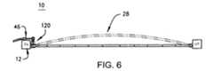
スプリングアセンブリ22は、ブラケット18,20に同様に取り付けられた一対の正弦スプリング58,60から形成されることが好ましい。正弦スプリング58,60の各々については、中央部28は正弦形状内へ曲げられた単一のワイヤから片持ち端部24,26とともに一体的に形成される。スプリング58,60は一対のコネクタ62,64によってともに保持されるが、本発明によれば、図4、図5および図6に示されるように、一対のうちのいずれか一つ、つまり正弦スプリング58または正弦スプリング60のいずれかを使用する。好適な実施形態においては、第一のループ66は回動可能に接続され、第一のブラケット18の回りに片持ち支持されていて、第一の片持ち端部24を区画し、最後のループ68は回動可能に接続され、第二のブラケット20の回りに片持ち支持されていて、第二の片持ち端部26を区画している。中央部28は一対のブラケット18,20との間で複数のループ70を有している。このループ70には、第一のループ66とともに一体に成形された第二のループ72と最後のループ68とともに一体に成形された第二から最後までのループ74が含まれる。 The
好適な実施形態で示されているように、第一の側部14は通常第二の側部16に対向し、第一の側部14はシートフレーム12の右側にあり、第二の側部16はシートフレーム12の左側にある。またシートフレーム12は、各々第一の側部14と第二の側部16として代わりに使用できる上部側部76と下部側部78とを具備している。また、本発明のものは、逆向きにも取り付けることができ、また、本発明のものは、シートフレーム12の下部80に取り付けてもよい。 As shown in the preferred embodiment, the
図1、図2および図3に示すように、第一と第二のブラケット18,20は、直接かつ剛体的に第一と第二の側部14,16に各々取り付けられる。ブラケットをシートフレームに溶接し、ブラケットを金具で取り付けたり、ブラケットをシートフレーム内に一体に成形したり、または、直接かつ剛体的に接続するような他の方法を使用することにより、上記のように固定接続することができる。また、ブラケット18,20とシートフレーム12との間の接続は、必ずしも直接的または剛体的である必要はない。非直接的な接続例としては、ブラケット18,20とシートフレーム12との間にコイルスプリング(図示せず)などのような追加構造エレメントが介挿されている場合が挙げられ、この場合には、接続は直接的でも剛体的でもない。その代わりに、ブラケット18,20は直接シートフレーム12に接続され、コイルスプリングは支持台32,34と各々のレバー40,42との間に介挿されていてもよい。剛体的ではない直接的な接続例としては、ブラケット18,20の支持台32,34またはシートフレームに一端で取り付けられ、レバーにもう一端で(図7参照)取り付けられたコイルスプリングといった、シートフレームに回動可能に取り付けられたループ(図示せず)を有するロッドが挙げられる。最終的に、ブラケットは、シートフレーム12を中央部28に対して実質的に垂直方向に横切るように設けられ、各々の側部14,16付近と離れた部分との第一および第二の支持台32,34を設けることができる。例えば、中央部28が(左右間で)シートフレーム12を水平方向に横切るような構成の場合には、ブラケットは上端側部および下端側部でフレームに取り付けられたフレームの対向側上での一対のほぼ平行なロッド(図示せず)とすることが可能である。かかる構成の場合、左側上のフレームを横切るように設けられたロッドにより左側付近に支持台を設けることができ、また右側のフレームを横切るように設けられたロッドにより右側付近に支持台を設けることができる。 As shown in FIGS. 1, 2 and 3, the first and
ランバーサポート装置10の変形実施形態を図4および図5に示す。正弦形状スプリング100は上述した好適な実施形態におけるスプリングアセンブリ22と同様に構成されており、中央部102は、窪み部分は設けられておらず、シートフレーム12を直線状に横切るように設けられている。スプリング100のみがシートフレーム12の第一の側部14で1つのレバー104を有しており、ボーデンケーブルアセンブリ106によってレバー104はアクチュエータ108と接続されている。ブラケット110は第一の側部14において剛体的にシートフレーム12に取り付けられている。また、ブラケット110はレバー104が掛けられるフック112を有しているので、レバー104はフック112内で回動するとともに、多少、摺動することができる。一体型ブラケット114はシートフレーム12の第二の側部16内で形成され、スプリング100の第二の端部116は回動可能に一体型ブラケット114に取り付けられる。 A modified embodiment of the
上記で開示されているように、窪み部がない場合には、中央部102はブラケット110,116間の直線長さと同じ長さとされる。フック112を具備するブラケット110により、アクチュエータ108は、レバー104のみを回転できるようにする場合に必要とされる力よりも少ない力で中央部102を折り曲げることができる。例えば、ブラケット110をループが具備されたブラケットに交換すると、好適な実施形態に示されるように、レバー104は摺動や平行移動をしなくなり、アクチュエータ108は中央部102内で曲げたり延ばしたりする力を作用させることになる。レバー104はブラケット114内で摺動することができるが、ブラケット114は、レバー104を摺動させないようにする支持台118を有してレバー104を強制的に回動させるべく、摺動が制限される。 As disclosed above, when there is no depression, the
図6及び図7は、ランバーサポート装置10の本発明に係る他の変形実施形態を示す。図6は、上述した他の実施形態とは反対側に向いているレバー120を示す。いずれの実施形態においても、スプリングが曲がり形状に形成されている場合には、レバーを逆方向に使用して、スプリングを平らにすることができ、この場合、牽引アクチュエータアセンブリをパルスアクチュエータアセンブリに置き換えたり、またその逆も可能である。図7は、ブラケットとして働く一対のコイルスプリング124を介してシートフレーム12に接続されたリーフスプリング122を示す。図1、図2および図3に示した好適な実施形態では、一対の正弦形状スプリング58,60と一対の片持ち端部24,26を具備するスプリングアセンブリ22が設けられているが、この変形実施形態ではランバーサポート装置10は単一のスプリングと単一の片持ち端部を備えていてもよく、また異なった種類のスプリングを作動させることも可能であることが明らかである。上説したランバーサポート装置10の各々の実施形態においては、どの支持台もレバーの端末部とスプリングの中央部との間に配置されるのが好ましい。 6 and 7 show another modified embodiment of the
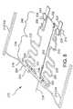
図8及び図9は、本発明に係るランバーサポート装置200の第四の変形実施形態を示す。第四の実施形態のランバーサポート装置200は、上述したスプリングアセンブリと同様に構成された本体202と、取付部204,206と、アクチュエータアセンブリ208とを備えて成る。本体202は、第一の端部マージン210と第二の端部マージン212とを有しており、基本的にワイヤで形成される。ワイヤは、シートアセンブリに使用されている公知の種類の金属スプリングワイヤが好ましい。本体の中間部213がその間で長手方向に延在するように、本体の第一の端部マージン210は好ましくは第一の取付部204,206に接続され、第二の端部マージン212は第二の取付部に接続されているのが好ましい。図8に示すように、ランバーサポート装置200の取付部204,206は、互いに間隔をあけて垂直に配置され、この場合に、ランバーサポート装置が取り付けられるシートのシートバック(図示せず)付近に本体202が配置されるように、シートフレーム214に取り付けるのが好ましい。このようにすれば、ランバーサポート装置200の本体202の長手方向寸法は、シートフレーム214の側部216に略平行に延在した寸法となる。 8 and 9 show a fourth modified embodiment of the
第四の実施形態のランバーサポート装置200の第一の取付部204は、好ましくは、一方のシートフレーム側部216から他方の側部へシートフレーム214の幅を横切る単一のワイヤ取付部218を有して成る。また、第一の取付部204は、好ましくは、ガラス補強ナイロンから形成されるコネクタ220から成る。コネクタ220は枢支的にワイヤ取付部218と本体202の第1の端部マージン210とに接続され、本体の第一の端部マージンは、ワイヤ取付部218に略平行とされ、かつ本体202の長手方向に対して垂直な軸の回りに枢支回動に設けられる。ランバーサポート装置200の第二の取付部206は、好ましくは、本体202の第二の端部マージン212の反対側側部224を側部216またはシートフレーム214の上端部へ接続する一対のブラケット222を有して成る。上記ブラケット222の各々は図4に示すランバーサポート装置10の変形実施形態のブラケット110と同様に構成されており、また、上記で説明したのと同様に、各々はフック226を具備して成る。図4に示すランバーサポート装置10の変形実施形態のブラケット110と同じく、フック226は、第二の端部マージンがブラケットに対して第一の端部マージン210に向かって所定距離だけ摺動し、その後回動のみ可能となるように、本体202の第二の端部マージン212の各々の側部224を保持している。 The first mounting
好ましくは、本体202は、本体の第一の端部マージン210から本体の第二の端部マージン212へ長手方向に延在しかつ2つの波状のスプリング230が形成され本体202の中間部213を横切るように、第一の端部マージンへ戻る単一の正弦形状ワイヤ228で形成されることが好ましい。2つの波状スプリング230は、通常は本体202の2つの中間部とみなすことができる。レバーアーム232は、ワイヤが第一の端部マージン210へループ状に戻ると、本体202の第二の端部マージン212において波形ワイヤ228によって形成される。図9を参照すると最も理解し易く、本体202の第二の端部マージン212におけるレバーアーム232は本体202から片持ち支持され、第二の取付部206のブラケット222の各フック226を介して延在する軸の回りにモーメントアームが形成される。同様にして、波形ワイヤ228の対向端部234は本体202の第一の端部マージン210において急角度で曲げられて、前記周辺部と共にこの位置で片持ち支持される一対のレバーアーム236を形成し、それらレバーアームの各々は、第一の取付部204のワイヤ取付部218の中央軸に対して、ともにモーメントアームを形成する。第一の端部マージン210のレバーアーム236は、好ましくは、第一の取付部204のコネクタ220によって連結され、また間隔をあけて保持される。図示されているように、第一の端部マージン210におけるレバーアーム236は、本体202の第二の端部マージン212におけるレバーアーム232より僅かに長い寸法とすることが好ましい。 Preferably, the
ランバーサポート装置200の第四の実施形態における本体202の要部は、波形スプリング230の構成にある。上述した実施形態とは異なり、第四の実施形態における各々の波状スプリング230の軌跡の正弦形状は、各々均等にされておらず、スプリング230は、本体202の中間部213を長手方向に横切るように設けられている。特に、本体202の中間部213は理論的に長手方向の軌跡に沿った点において、曲げ剛性が異なり長手方向に延在する第一および第二の小部分238,240に分割することができる。波状スプリング230が長手方向に本体の中間部213を横切るときに、各波状スプリング230の波形を変化させることにより曲げ剛性に差を生じさせることが好ましい。特に、第一の小部分238内における各々の波状スプリング230の波形は、第二の小部分240における平均周波数および平均振幅より大きいことが好ましい。こうした場合の直接的な結果として、中間部213の第一の小部分238は実質的に第二の小部分240よりも小さい曲げ剛性を有すると、第一の小部分は第二の小部分よりも曲がり易くなることが当業者には容易に理解される。この柔軟性の差が、曲げ応力を受けて使用されるときに、本体202の長手方向の軌跡の形状に影響を与える。以下で説明するように、より好ましい方法としては、本体を非対称に折り曲げることが挙げられる。 The main part of the
第四の実施形態におけるランバーサポート装置200のアクチュエータアセンブリ208は、好ましくは図1〜図3に示す好適実施形態のアクチュエータアセンブリと同様に構成され、アクチュエータアセンブリの特定の種類と構成はこの実施形態では特に重要ではない。アクチュエータアセンブリ208は、好ましくは選択的に物体間で牽引力を発生させるように構成かつ適用されるボーデンケーブル242を有して成る。図9において明示されているように、アクチュエータアセンブリ208は動作可能なように本体202の各端部マージン210,212のレバーアーム232,236に接続され、作動時には、ここでアクチュエータアセンブリは、レバーが互いに力をかけるように作動する。 The
第四の実施形態におけるランバーサポート装置は、通常は図4および図5に示されるランバーサポート装置10と同様に作動する。最初の位置では、図9において実線で示されるように、本体202の中間部213の長手方向の軌跡は実質的に直線状に延在する。さらに、最初の位置では本体202の第二の端部マージン212は、図4および図5に示されているようなフック226の構成とされているので、第二の取付部206のブラケット222に対して、第一の端部マージン210方向に自由に所定距離だけ摺動することができる。所望の場合には、アクチュエータアセンブリ208を作動させて本体202の端部マージン210,212のレバーアーム232,236間で牽引力を発生させることができる。上記で説明した実施形態と同様に、レバーアーム232,236上での牽引力により、各端部マージン210,212内で曲げモーメントが誘起され、このモーメントにより中間部213の長手方向に軌跡が発生し、第二の位置へ曲がり、この位置で横幅方向に対して垂直方向に外側に向かって折り曲げられる。この状態は、図9において点線で示されている。 The lumbar support device in the fourth embodiment normally operates in the same manner as the
これまで説明したランバーサポート装置の実施形態とは異なり、第四の実施形態のランバーサポート装置200の本体202は、非対称形状に折り曲げられる。この非対称の折れ曲がりは、上記で説明したように中間部213の構成が少なくとも一部の要因とされるが、その結果、第一の小部分の曲げ剛性は第二の小部分240の曲げ剛性より実質的に小さくなる。この曲げ剛性により、所定の誘起された曲げモーメントに関し、第一の小部分238にわたる本体202の中間部213の長手方向の軌跡は、第二の小部分240の軌跡よりも曲率が増加する。従って、第一の小部分213の長手方向の軌跡は、第二の小部分240と比較すると、第一の小部分238にわたってさらに外側へ膨らむ傾向がある。アクチュエータアセンブリ208により本体202にわたって誘起される曲げモーメントは必ずしも一定ではないが、第一および第二の小部分238,240間の曲げモーメントの差は、上記のような膨らみの少なくとも一部の原因ともなる。また、本体202は、好ましくは、第一の長手方向半分割部238がシートフレーム214に対して第二の半分割部240の下部に配置されるように配向され、人がシートにもたれると本体の第一の半分割部が人のランバー部付近に配置されるようにされる。つまり、第二の小部分240に比較して、本体202の中間部213の第一の小部分238が不均等に膨らんだり或いは曲折したりすることが、必要に応じてさらにランバーを支持するために望ましい。 Unlike the embodiments of the lumbar support device described so far, the
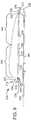
図10に示す第五の実施形態におけるランバーサポート装置300は、実質的に第四の実施形態におけるランバーサポート装置200と同様な構成を有しており、本体302、第一の取付部304、およびアクチュエータアセンブリ306を備えている。しかし、第五の実施形態におけるランバーサポート装置300の第二の取付部308は、本体302の第二の端部マージン314の対向側部312を装置が配置されているシートフレーム318の側部316へ動作可能なように接続する一対のコイルテンションスプリング310を有している。 A
操作時には、コイルテンションスプリング310は、第四の実施形態におけるランバーサポート装置200のブラケット222と同様に作動し、本体がアクチュエータアセンブリ306によって折り曲げられると、本体302の第二の端部マージン314が本体の第一の端部マージン320に向かって平行移動できるようになる。しかし、第四の実施形態におけるランバーサポート装置200のブラケット222とは異なり、コイルテンションスプリング310は弾性的に延在することにより、このような動きを実現できるので、コイルテンションスプリングと本体302との間の相対的な摺動は発生しない。つまり、上記で説明した第四の実施形態におけるランバーサポート装置202に比較して、第五の実施形態におけるランバーサポート装置302は、使用時に、摩耗したり固着したりする傾向が少なく、また、より簡易な構造とされる。 In operation, the
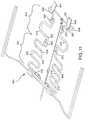
図11は、ランバーサポート装置400の他の実施形態を示す。このランバーサポート装置400の第六の実施形態は、上記で説明した第四および第五の実施形態と同様な効果が得られるように構成かつ適用されたものであるが、本体402の構成が異なる。第四および第五の実施形態の本体202,302と同様に、第六の実施形態におけるランバーサポート装置400の本体402は、本体の第一および第二の端部マージン406,408との間の本体の中間部405を長手方向に横切るように設けられた一対の波形スプリング404を備えて成る。ただし、第四および第五の実施形態におけるランバーサポート装置200,300とは異なり、中間部405の第一の小部分412にわたるワイヤの平均径が中間部の第二の小部分414にわたるワイヤの平均径より小さくなるように長手方向に伸びると、各々の波形スプリング404を形成するワイヤ410は、基準寸法(ゲージ)が変更される。図11で示されるように、環状バンド420で大径ワイヤ416の部分が小径ワイヤ部418に圧着すると、基準寸法が変えられる。その代わりに、異なった基準ワイヤ部を突合せ溶接して、基準寸法が変化する連続ワイヤ(図示せず)を形成するか、または当業者が理解できる他の適当な技術を用いて同様な作用効果を得ることができる。例えば、長手方向の軌跡に沿って、異なった基準寸法のワイヤを最初に形成したり、または異なる材料特性のワイヤ部を使用することにより同様な作用効果が得られる。 FIG. 11 shows another embodiment of the
上記で説明したように1つ以上の基準寸法となるワイヤで構成されるので、本体402の中間部405の第一の小部分412での曲げ剛性は第二の小部分414の曲げ剛性より遥かに小さくなり、必ずしも異なった波形形状を有する必要はない。この場合、本体402の中間部405の第一の小部分412は、本体が曲げモーメントを受けると、第二の小部分414よりも曲率が増加する傾向がある。 As described above, since the wire is composed of one or more reference dimensions, the bending rigidity at the first
第四および第五の実施形態におけるランバーサポート装置200,300に対し、第六の実施形態におけるランバーサポート装置400を比較した場合の差は、第二の取付部422である。第六の実施形態におけるランバーサポート装置400の第二の取付部422は、閉ループ端部426を有する一対のブラケット424から構成され、閉ループ端部426により第二の端部マージン408とそのブラケットとの間で枢支運動のみが可能となり、図1〜図3、また上記で説明したブラケットと同様である。 A difference when the
上記で説明した相違のほかにも、第六の実施形態におけるランバーサポート装置400は、第四および第五の実施形態におけるランバーサポート装置200,300と同様な点がある。つまり、この第六の実施形態におけるランバーサポート装置の本体402は、第四および第五の実施形態の本体202,302とよく似た作動をし、作動時には同様な所望の不均一な可撓動作を行なうことが理解される。 In addition to the differences described above, the
本発明の範囲から逸脱することなく、本文で記載、示されている構造や方法により種々の変形が可能であるので、上記の説明に含まれ、または添付図面に示されている項目全ては限定されるものではないと解釈されるべきである。例えば、本発明では特に正弦形状スプリングとリーフスプリングを使用して説明しているが、リーフスプリングと正弦形状スプリングとで製作された複合スプリングまたはコイルスプリングを使用した組合せなどの一体型成形スプリング、またはスプリングの組合せを本文で説明したスプリングに交換できることは当業者にとって明らかである。よって、本発明の範囲は上記で説明した実施形態により制限されるものではなく、請求の範囲及びその等価な範囲によって定義されなければならない。 Various modifications may be made by the structures and methods described and shown herein without departing from the scope of the invention, so that all items contained in the above description or shown in the accompanying drawings are limited. It should be construed as not being done. For example, although the present invention is described using a sinusoidal spring and a leaf spring in particular, an integrally formed spring such as a composite spring or a combination using a coil spring made of a leaf spring and a sinusoidal spring, or It will be apparent to those skilled in the art that the combination of springs can be replaced with the springs described herein. Therefore, the scope of the present invention is not limited by the embodiments described above, but must be defined by the claims and their equivalents.
Claims (40)
Translated fromJapanese前記第一のブラケットから離隔配置される第二のブラケットと、
第一の片持ち端部、第二の端部、および前記第一の片持ち端部と前記第二の端部と共に一体形成された中央部を有しており、前記第一の片持ち端部は前記第一のブラケットに回動可能に接続かつ片持ち支持され、前記第二の端部は前記第二のブラケットに接続され、前記中央部は前記第一のブラケットと前記第二のブラケットとの間を横切るように設けられており、前記第一の片持ち端部は、前記第一の支持台が第一の端末部と中央部との間に配置されるように前記第一の支持台から前記第一の端末部へ延在する第一のレバーを画定する、第一のスプリングと、
前記第一のレバーの前記第一の端末部に動作可能なように接続され、前記第一の端末部を移動させ、前記支持台が前記第一のレバーの摺動を停止させ、かつ前記第一のレバーを強制的に回転させるように設けられたアクチュエータアセンブリと、
を備えるランバーサポート装置。A first bracket having a first support;
A second bracket spaced apart from the first bracket;
A first cantilever end, a second end, and a central portion integrally formed with the first cantilever end and the second end; The first bracket is pivotally connected and cantilevered, the second end is connected to the second bracket, and the central portion is the first bracket and the second bracket. And the first cantilevered end is arranged such that the first support base is disposed between the firstterminal portion and the central portion. A first spring defining a first lever extending from the support to the firstend ;
The first is operatively connected to the firstterminal portion of the lever, said firstterminal portion to move said support table stops the sliding of the first lever, and the second An actuator assembly provided to force one lever to rotate;
A lumbar support device comprising:
請求項1に記載のランバーサポート装置。A seat frame having a first side for attaching the first bracket and a second side for attaching the second bracket;
The lumbar support device according to claim 1.
請求項1に記載のランバーサポート装置。The first spring is a sinusoidal spring;
The lumbar support device according to claim 1.
前記正弦形状スプリングの中央部は、中間部をさらに含んでおり、
前記中間部は、第一の小部分と第二の小部分とをさらに含んでおり、
前記第一の小部分は、前記第二の小部分の平均曲げ剛性よりも小さい曲げ剛性を有する、請求項3に記載のランバーサポート装置。The sinusoidal spring is a continuous wire having a sinusoidal shape;
The central portion of the sinusoidal spring further includes an intermediate portion,
The intermediate portion further includes a first small portion and a second small portion,
The lumbar support device according to claim 3, wherein the first small portion has a bending rigidity smaller than an average bending rigidity of the second small portion.
請求項1に記載のランバーサポート装置。The first spring is a leaf spring;
The lumbar support device according to claim 1.
請求項1に記載のランバーサポート装置。The first bracket further comprises a coil spring;
The lumbar support device according to claim 1.
前記第二の端部は、回動可能に前記第二のブラケットに接続かつ片持ち支持され、
前記第二の端部は、前記第二の支持台から第二の端末部へ延在する第二のレバーを画定し、
前記アクチュエータアセンブリは、前記第一の端末部を動作可能なように前記第二の端末部へ接続する、
請求項1に記載のランバーサポート装置。The second bracket further comprises a second support;
The second end is pivotally connected and cantilevered to the second bracket;
It said second end defining a second lever extending from said second support base to the secondterminal portion,
It said actuator assembly is connected to the first saidterminal portion operably secondterminal portion,
The lumbar support device according to claim 1.
請求項1に記載のランバーサポート装置。A central portion of the spring assembly further has a recess;
The lumbar support device according to claim 1.
前記一対のコネクタにより前記第一のスプリングが前記第二のスプリングに取り付けられる、
請求項1に記載のランバーサポート装置。A second spring and a pair of connectors;
The first spring is attached to the second spring by the pair of connectors,
The lumbar support device according to claim 1.
前記第一のブラケットから離隔配置される第二のブラケットと、
第一の片持ち端部、第二の端部、および、前記第一の片持ち端部と第二の端部とに固設された中央部を有しており、前記第一の片持ち端部は前記第一のブラケットに回動可能に接続かつ片持ち支持され、前記第二の端部は前記第二のブラケットに接続され、前記中央部は前記第一の片持ち端部と第二の端部との間を横切るように設けられており、前記第一の片持ち端部は、前記第一の支持台が第一の端末部と中央部との間に配置されるように前記第一の支持台から前記第一の端末部へ延在する第一のレバーを画定する、スプリングアセンブリと、
前記第一のレバーの前記第一の端末部に動作可能なように接続され、前記第一の端末部を移動させ、前記支持台が前記第一のレバーの摺動を停止させ、かつ前記第一のレバーを強制的に回転させるように設けられたアクチュエータアセンブリと、
を備えるランバーサポート装置。A first bracket having a first support;
A second bracket spaced apart from the first bracket;
A first cantilevered end, a second end, and a central portion fixed to the first cantilevered end and the second end; An end is pivotally connected and cantilevered to the first bracket, the second end is connected to the second bracket, and the center is connected to the first cantilevered end The first cantilever end is disposed between the first endportion and the central portion so as to cross between the two end portions. A spring assembly defining a first lever extending from the first support to the firstend ;
The first is operatively connected to the firstterminal portion of the lever, said firstterminal portion to move said support table stops the sliding of the first lever, and the second An actuator assembly provided to force one lever to rotate;
A lumbar support device comprising:
請求項14に記載のランバーサポート装置。A seat frame having a first side for attaching the first bracket and a second side for attaching the second bracket;
The lumbar support device according to claim 14.
前記第二の端部は、回動可能に前記第二のブラケットに接続かつ片持ち支持され、
前記第二の端部は、前記第二の支持台から第二の端末部へ延在する第二のレバーアームを画定し、
前記アクチュエータアセンブリは、前記第一の端末部を動作可能なように前記第二の端末部へ接続する、
請求項14に記載のランバーサポート装置。The second bracket further comprises a second support;
The second end is pivotally connected and cantilevered to the second bracket;
Said second end defining a second lever arm extending from said second support base to the secondterminal portion,
It said actuator assembly is connected to the first saidterminal portion operably secondterminal portion,
The lumbar support device according to claim 14.
請求項14に記載のランバーサポート装置。A central portion of the spring assembly further has a recess.
The lumbar support device according to claim 14.
前記アクチュエータは、ボーデンケーブルアセンブリと動作可能なように係合し、
前記ボーデンケーブルアセンブリは、前記第一の端末部を前記第二の端末部に牽引するように連結させる、
請求項14に記載のランバーサポート装置。The actuator assembly further includes a Bowden cable and an actuator,
The actuator operatively engages a Bowden cable assembly;
The Bowden cable assembly coupling the said firstterminal portion so as to pull the secondend portion,
The lumbar support device according to claim 14.
前記正弦形状スプリングの中央部は、中間部をさらに含んでおり、
前記中間部は、第一の小部分と第二の小部分とをさらに含んでおり、
前記第一の小部分は、前記第二の小部分の平均曲げ剛性よりも小さい曲げ剛性を有する、請求項14に記載のランバーサポート装置。The spring assembly is a continuous wire having a sinusoidal shape;
The central portion of the sinusoidal spring further includes an intermediate portion,
The intermediate portion further includes a first small portion and a second small portion,
15. The lumbar support device according to claim 14, wherein the first small portion has a bending rigidity smaller than an average bending rigidity of the second small portion.
前記第一のループは、前記第一の片持ち端部を画定し、
前記最終ループは、前記第二の片持ち端部を画定し、
前記複数のループは、前記中央部を画定し、かつ第二のループと第二−最終ループをさらに有しており、
前記第二のループは、前記第一のループと一体形成されており、
前記第二−最終ループは、前記最終ループと一体形成されている、
請求項14に記載のランバーサポート装置。The spring assembly further includes a sinusoidal spring having a first loop, a final loop, and a plurality of loops;
The first loop defines the first cantilevered end;
The final loop defines the second cantilevered end;
The plurality of loops further define a central portion and further includes a second loop and a second-final loop;
The second loop is integrally formed with the first loop,
The second-final loop is integrally formed with the final loop;
The lumbar support device according to claim 14.
本質的にワイヤで構成されており、対向する第一および第二の長手方向端部マージンの間を長手方向の軌跡に沿って延在し、前記第一の長手方向端部マージンは動作可能なように前記第一の取付部に接続され、前記第二の端部マージンは動作可能なように前記第二の取付部に接続され、前記第一の取付部と前記第二の取付部との間の前記長手方向の軌跡に沿って延在する中間部をさらに含んでおり、前記中間部は第一と第二の小部分をさら含んであり、前記ワイヤは、前記第一の小部分が前記第二の小部分の平均曲げ剛性より小さい平均曲げ剛性を有するように構成され、かつ前記第二の端部マージンは前記第二の取付部に対して片持ち梁状に延在するレバーアームを含む、本体と、
前記レバーアームを介して動作可能なように前記本体へ接続されたアクチュエータアセンブリであって、前記本体の前記長手方向の軌跡が第一と第二の位置との間で選択的に屈曲可能なように、かつ前記レバーアームを介して前記本体の前記第二の端部マージン内で曲げモーメントを誘起するように構成かつ適用され、前記第一と第二の小部分の各々に沿った前記長手方向の軌跡は、前記長手方向の軌跡が前記アクチュエータアセンブリを介して前記第一と第二の位置との間で屈曲すると曲率が変化し、前記第一の小部分に沿った前記長手方向の軌跡の曲率変化は、前記第一の小部分と前記第二の小部分との間の平均曲げ剛性の差により、前記第二の小部分に沿った長手方向の軌跡の曲率変化より大きい、アクチュエータアセンブリと、
を備えるランバーサポート装置。First and second mounting portions spatially spaced from each other;
Consists essentially of wire and extends between opposing first and second longitudinal end margins along a longitudinal trajectory, said first longitudinal end margin being operable Connected to the first mounting portion, and the second end margin is operably connected to the second mounting portion, and the first mounting portion and the second mounting portion Further including an intermediate portion extending along the longitudinal trajectory therebetween, the intermediate portion further including first and second small portions, and the wire includes the first small portion. A lever arm configured to have an average bending stiffness smaller than an average bending stiffness of the second small portion, and the second end margin extending in a cantilever manner with respect to the second mounting portion Including the body,
Anactuator assembly connected to the body for operation via the lever arm, wherein the longitudinal trajectory of the body is selectively bendable between a first and a second position; And configured to induce a bending moment in the second end margin of the body via the lever arm and the longitudinal direction along each of the first and second sub-portions The trajectory of the longitudinal trajectory changes when the trajectory in the longitudinal direction is bent between the first and second positions via the actuatorassembly , and the trajectory of the longitudinal trajectory along the first small portion is changed. A change in curvature greater than a change in curvature of a longitudinal trajectory along the second small portion due to a difference in average bending stiffness between the first small portion and the second small portion; and ,
A lumbar support device comprising:
前記少なくとも1本の連続ワイヤは、前記ワイヤが前記本体の前記長手方向の軌跡に沿って延在するときに波形形状を有するように形成される、
請求項21に記載のランバーサポート装置。The wire includes at least one continuous wire extending from the first end margin of the body to the second end margin;
The at least one continuous wire is formed to have a corrugated shape when the wire extends along the longitudinal trajectory of the body.
The lumbar support device according to claim 21.
請求項22に記載のランバーサポート装置。The at least one continuous wire usually has a constant diameter;
The lumbar support device according to claim 22.
請求項22に記載のランバーサポート装置。The waveform shape has an average frequency and an average amplitude that are greater than the waveform shape of the second sub-portion over the first sub-portion of the intermediate portion;
The lumbar support device according to claim 22.
請求項22に記載のランバーサポート装置。The wire comprises the one continuous wire;
The lumbar support device according to claim 22.
請求項22に記載のランバーサポート装置。The continuous wire further includes at least two intermediate portions between the first and second end margins;
The lumbar support device according to claim 22.
請求項26に記載のランバーサポート装置。The lever arm is formed by the continuous wire between the two intermediate portions;
The lumbar support device according to claim 26.
請求項27に記載のランバーサポート装置。The lever arm is formed between the second small portions of the two intermediate portions;
The lumbar support device according to claim 27.
前記第一の端部レバーアームは、第一の取付部に対して片持ち梁状に延在し、
前記アクチュエータアセンブリは、前記第一の端部レバーアームを介して前記本体の前記第一の端部マージンへ曲げモーメントを誘起することができるように、かつ、動作可能なように、前記第一の端部レバーアームを介して前記本体へ接続される、
請求項27に記載のランバーサポート装置。The first end margin further comprises a first end lever arm formed by the continuous wire;
The first end lever arm extends in a cantilever shape with respect to the first mounting portion,
The actuator assembly is operable to induce and bend a bending moment to the first end margin of the body via the first end lever arm. Connected to the body via an end lever arm,
The lumbar support device according to claim 27.
請求項29に記載のランバーサポート装置。The second mounting portion further includes a pair of coil springs,
The lumbar support device according to claim 29.
請求項21に記載のランバーサポート装置。The wire includes a large diameter wire in the first small portion and a small diameter wire in the second small portion;
The lumbar support device according to claim 21.
請求項21に記載のランバーサポート装置。The second attachment portion has the second end margin of the main body in a direction toward the first attachment portion when the longitudinal trajectory is first bent through the actuator. It is configured to be able to translate relative to the second mounting part.
The lumbar support device according to claim 21.
請求項21に記載のランバーサポート装置。The first mounting portion and the first end margin of the main body so that the first end margin of the main body can pivot about an axis that is normally parallel to the first mounting portion. Further comprising a connector connected to be pivotally pivotable to
The lumbar support device according to claim 21.
前記第一の取付部が動作可能なように前記本体の前記第一の端部マージンが前記シートフレームの前記第一の側部へ接続され、
前記第二の取付部が動作可能なように前記本体の前記第二の端部マージンが前記シートフレームの前記第二の側部へ接続される、
請求項21に記載のランバーサポート装置。Comprising a seat frame having a first side and a second side;
The first end margin of the body is connected to the first side of the seat frame so that the first attachment is operable;
The second end margin of the body is connected to the second side of the seat frame so that the second attachment is operable;
The lumbar support device according to claim 21.
本質的にワイヤで構成されており、長手方向に対向する第一および第二の端部マージンの間を長手方向の軌跡に沿って延在し、前記前記第一の端部マージンは動作可能なように前記第一の取付部に接続され、前記第二の端部マージンは動作可能なように前記第二の取付部に接続され、前記第一の端部マージンは前記第一の取付部に対して片持ち梁状に延在する第一の端部レバーアームを含む、本体と、
前記本体の前記第一の端部マージンが前記第一の取付部に通常平行である軸の回りを枢支回動するように、前記本体の前記第一の取付部と前記第一の端部レバーアームとに枢支回動可能に接続されたコネクタと、
前記コネクタを介して動作可能なように前記本体に接続されており、増加する曲げモーメントに応じて前記本体の前記長手方向の軌跡の曲率が増加するように、前記本体の前記第一の端部マージン内で前記増加する曲げモーメントを、前記コネクタを介して選択的に誘起するように構成かつ適用される、アクチュエータアセンブリと、
を備えるランバーサポート装置。First and second mounting portions spatially spaced from each other;
It consists essentially of wire and extends along a longitudinal trajectory between first and second longitudinally opposite margins, said first margin being operable Connected to the first mounting portion, the second end margin is operably connected to the second mounting portion, and the first end margin is connected to the first mounting portion. A body including a first end lever arm extending in a cantilevered manner,
The first attachment portion and the first end portion of the body so that the first end margin of the body pivots about an axis that is normally parallel to the first attachment portion. A connector pivotably connected to the lever arm;
The first end of the main body is connected to the main body so as to be operable via the connector, and the curvature of the longitudinal trajectory of the main body increases in response to an increasing bending moment. An actuator assembly configured and applied to selectively induce the increasing bending moment through the connector within a margin;
A lumbar support device comprising:
前記少なくとも1本の連続ワイヤは、前記本体の前記長手方向の軌跡に沿って延在しかつ前記第二の端部マージンでレバーアームを形成するときに波形形状となるように形成され、前記レバーアームは前記第二の取付部に対して片持ち梁状に延在し、かつ前記アクチュエータアセンブリが前記レバーアームを介して前記本体の前記第二の端部マージン内で曲げモーメントを誘起するように構成かつ適用される、
請求項35に記載のランバーサポート装置。The wire includes at least one continuous wire extending from the first end margin of the body to the second end margin of the body;
The at least one continuous wire extends along the longitudinal trajectory of the main body and is formed to have a waveform when the lever arm is formed with the second end margin, and the lever The arm extends in a cantilevered manner with respect to the second mounting portion, and the actuator assembly induces a bending moment within the second end margin of the body via the lever arm. Configured and applied,
The lumbar support device according to claim 35.
前記第二の取付部は、一対のコイルスプリングを含む、
請求項36に記載のランバーサポート装置。The continuous wire further includes at least two intermediate portions between the first and second end margins;
The second attachment portion includes a pair of coil springs.
The lumbar support device according to claim 36.
前記長手方向の軌跡は、前記第一と第二の取付部との間にある1つの点を有し、
前記点は長手方向に対向する方向に前記点から延在する前記中間部の第一と第二の小部分を画定し、かつともに前記中間部の全体を構成し、
前記少なくとも1本の連続ワイヤの波形形状は、前記第一の小部分が前記第二の小部分の平均曲げ剛性より小さい平均曲げ剛性を有し、
前記本体が前記長手方向の軌跡に沿って延在するときに、前記本体の第一の小部分が第一の端部マージンを第二の小部分から分離する、
請求項36に記載のランバーサポート装置。The body further includes an intermediate portion extending along a longitudinal trajectory between the first attachment portion and the second attachment portion,
The longitudinal trajectory has one point between the first and second attachments;
The point defines first and second small portions of the intermediate portion extending from the point in a direction opposite the longitudinal direction, and together constitutes the entire intermediate portion;
The corrugated shape of the at least one continuous wire has an average bending stiffness in which the first small portion is less than the average bending stiffness of the second small portion;
A first small portion of the body separates a first end margin from a second small portion when the body extends along the longitudinal trajectory;
The lumbar support device according to claim 36.
請求項35に記載のランバーサポート装置。When the curvature of the main body is increased for the first time, the second attachment portion is directed to the second attachment portion in a direction in which the second end margin of the main body is directed toward the first attachment portion. Configured to translate,
The lumbar support device according to claim 35.
前記第一の取付部は、動作可能なように前記本体の前記第一の端部マージンを前記シートフレームの前記第一の側部に接続し、
前記第二の取付部は、動作可能なように前記本体の前記第二の端部マージンを前記シートフレームの前記第二の側部に接続する、
請求項35に記載のランバーサポート装置。Further comprising a seat frame having first and second sides;
The first attachment portion is operable to connect the first end margin of the body to the first side of the seat frame;
The second attachment portion is operable to connect the second end margin of the body to the second side of the seat frame;
The lumbar support device according to claim 35.
Applications Claiming Priority (2)
| Application Number | Priority Date | Filing Date | Title |
|---|---|---|---|
| US09/832,692US6402246B1 (en) | 2001-04-11 | 2001-04-11 | Simplified strap lumbar support device |
| PCT/US2002/011399WO2002083029A2 (en) | 2001-04-11 | 2002-04-11 | Lumbar support device |
Publications (2)
| Publication Number | Publication Date |
|---|---|
| JP2004527304A JP2004527304A (en) | 2004-09-09 |
| JP4057427B2true JP4057427B2 (en) | 2008-03-05 |
Family
ID=25262366
Family Applications (1)
| Application Number | Title | Priority Date | Filing Date |
|---|---|---|---|
| JP2002580837AExpired - Fee RelatedJP4057427B2 (en) | 2001-04-11 | 2002-04-11 | Lumber support device |
Country Status (10)
| Country | Link |
|---|---|
| US (2) | US6402246B1 (en) |
| EP (1) | EP1377190B1 (en) |
| JP (1) | JP4057427B2 (en) |
| KR (1) | KR100863763B1 (en) |
| CN (1) | CN1268259C (en) |
| AT (1) | ATE300898T1 (en) |
| AU (1) | AU2002258768B2 (en) |
| CA (1) | CA2443737C (en) |
| DE (1) | DE60205355T2 (en) |
| WO (1) | WO2002083029A2 (en) |
Families Citing this family (54)
| Publication number | Priority date | Publication date | Assignee | Title |
|---|---|---|---|---|
| US6644740B2 (en)* | 2000-06-28 | 2003-11-11 | Lear Corporation | Vehicle seat lumbar support system |
| US20030001424A1 (en)* | 2001-06-27 | 2003-01-02 | David Mundell | Integral elastomeric suspension article and manufacturing process |
| CA2450735A1 (en)* | 2001-07-11 | 2003-01-23 | Alfmeier Corporation | Integrated adjustable lumbar support and trim attachment system |
| JP3975282B2 (en)* | 2001-11-29 | 2007-09-12 | テイ・エス テック株式会社 | Seat back tension structure |
| US6814407B2 (en)* | 2002-06-05 | 2004-11-09 | L & P Property Management Company | Single actuator four-way power lumbar |
| US7288998B2 (en)* | 2003-05-02 | 2007-10-30 | Silicon Laboratories Inc. | Voltage controlled clock synthesizer |
| US7097247B2 (en)* | 2003-06-05 | 2006-08-29 | Steelcase Development Corporation | Seating unit with adjustable lumbar device |
| US6918634B2 (en)* | 2003-07-22 | 2005-07-19 | Henderson's Industries Pty Ltd | Lumbar support |
| DE202004002569U1 (en)* | 2004-02-19 | 2005-07-07 | Schwarzbich, Jörg | lumbar support |
| US7252335B2 (en)* | 2004-03-12 | 2007-08-07 | L&P Property Management Company | Lumbar with flexwires in cross |
| US7281761B2 (en)* | 2004-05-03 | 2007-10-16 | Ford Global Technologies, Llc | Seat configuration system for an automotive interior |
| US7530636B2 (en)* | 2004-12-03 | 2009-05-12 | L&P Property Management Company | Comfort belt lumbar |
| WO2006060811A2 (en)* | 2004-12-03 | 2006-06-08 | L & P Property Management Company | Comfort belt lumbar |
| US7125076B2 (en)* | 2005-01-07 | 2006-10-24 | Ford Global Technologies, Llc | Automotive multi-position seat assembly |
| US7387338B2 (en)* | 2005-01-07 | 2008-06-17 | Ford Global Technologies, Llc | Automotive multi-position seat assembly |
| PT1680984E (en)* | 2005-01-12 | 2007-09-04 | L&P Swiss Holding Co | Lumbar support assembly and corresponding seat structure |
| PT1688065E (en)* | 2005-02-07 | 2008-12-26 | L&P Swiss Holding Co | Lumbar support device |
| CA2829902C (en) | 2005-03-01 | 2014-07-15 | Haworth, Inc. | Chair back with lumbar and pelvic supports |
| US20060226683A1 (en)* | 2005-04-08 | 2006-10-12 | Alfmeier Corporation | Adjustable lumbar support with extensive configurability |
| ATE526199T1 (en)* | 2005-04-08 | 2011-10-15 | Alfmeier Praez Ag | VEHICLE SEAT WITH LUMBAR SUPPORT |
| CN101212918B (en) | 2005-05-18 | 2010-07-28 | 舒克拉北美有限公司 | Dual hinge belt lumbar |
| US7780233B2 (en)* | 2005-06-02 | 2010-08-24 | Schukra Of North America, Ltd. | Belt extension apparatus |
| US7318286B1 (en)* | 2005-06-10 | 2008-01-15 | Haworth, Inc. | Apparatus and process for determining lumbar configuration in a chair |
| DE602005011591D1 (en)* | 2005-06-15 | 2009-01-22 | L&P Swiss Holding Co | Zugseilanordnung and the Zugseilanordnung using adjustable support device |
| DE102005036774B4 (en)* | 2005-08-04 | 2011-03-31 | Schukra Gerätebau AG | lumbar support |
| US7425036B2 (en)* | 2005-08-23 | 2008-09-16 | Schukra Of North America, Ltd. | Comfort belt spring pulley |
| US7775603B2 (en)* | 2006-06-29 | 2010-08-17 | L & P Property Management Company | Seat suspension system and seat cushion module holder |
| KR101006071B1 (en)* | 2006-12-11 | 2011-01-06 | 슈크라 오브 노스 아메리카 리미티드 | Climate Response Seat Spinal System |
| CA2655083C (en)* | 2008-02-22 | 2016-07-05 | Schukra Of North America | Constant pressure retreating lumbar system |
| US7806477B2 (en)* | 2008-02-29 | 2010-10-05 | La-Z-Boy Incorporated | Furniture member lumbar support system |
| ATE499234T1 (en)* | 2008-12-17 | 2011-03-15 | Fiat Ricerche | LUMBAR SUPPORT FOR VEHICLE BACKREST |
| DE202009000627U1 (en)* | 2009-01-20 | 2010-03-18 | Rücker GmbH | Adjustable lumbar support with eccentric mounting |
| US8096928B2 (en)* | 2009-08-05 | 2012-01-17 | Izhuk Ovadia | Device for treating the lower back |
| US8474909B2 (en) | 2010-09-21 | 2013-07-02 | La-Z-Boy Incorporated | Power lift lumbar support system |
| JP5621520B2 (en)* | 2010-11-05 | 2014-11-12 | トヨタ紡織株式会社 | Vehicle seat |
| USD707976S1 (en) | 2013-06-07 | 2014-07-01 | Steelcase Inc. | Chair |
| USD706547S1 (en) | 2013-06-07 | 2014-06-10 | Steelcase Inc. | Chair |
| USD703987S1 (en) | 2013-06-07 | 2014-05-06 | Steelcase Inc. | Chair |
| US9661930B2 (en) | 2012-09-21 | 2017-05-30 | Steelcase Inc. | Chair construction |
| USD721529S1 (en) | 2013-06-07 | 2015-01-27 | Steelcase Inc. | Handle apparatus |
| USD703988S1 (en) | 2013-06-07 | 2014-05-06 | Steelcase Inc. | Chair |
| USD704487S1 (en) | 2013-06-07 | 2014-05-13 | Steelcase Inc. | Chair |
| KR101545928B1 (en)* | 2015-04-03 | 2015-08-20 | (주)디에스시 | Lumbar Support Assembly |
| US9826841B2 (en) | 2015-12-24 | 2017-11-28 | L&P Property Management Company | Chair back with adjustable lumbar support |
| US10130185B2 (en)* | 2016-02-02 | 2018-11-20 | L&P Property Management Company | Adjustable lumbar support for upholstery furniture |
| US10085564B2 (en)* | 2016-02-02 | 2018-10-02 | L & P Property Management Company | Adjustable lumbar support for upholstery furniture |
| EP3530149B1 (en)* | 2018-02-22 | 2022-06-01 | Pullmaflex Benelux N.V. | Suspension arrangement for a seat and method of producing an elongate suspension member for a suspension arrangement for a seat |
| ES2848864T3 (en)* | 2018-06-25 | 2021-08-12 | Starsprings Ab | Firmness control device for a bed or seat arrangement |
| US11672348B2 (en) | 2018-11-05 | 2023-06-13 | La-Z-Boy Incorporated | Furniture member having lumbar adjustment mechanism |
| US11324324B2 (en) | 2018-11-05 | 2022-05-10 | La-Z-Boy Incorporated | Furniture member having lumbar adjustment mechanism |
| US10952535B2 (en)* | 2018-11-05 | 2021-03-23 | La-Z-Boy Incorporated | Furniture member having lumbar adjustment mechanism |
| US11246420B1 (en) | 2019-03-01 | 2022-02-15 | Ashley Furniture Industries, Llc | Adjustable lumbar support |
| CN111956376B (en)* | 2020-08-27 | 2023-04-07 | 湖南省森晖能动智能技术有限责任公司 | Upper part of body dresses device |
| USD1063474S1 (en) | 2022-09-07 | 2025-02-25 | Steelcase Inc. | Chair |
Family Cites Families (33)
| Publication number | Priority date | Publication date | Assignee | Title |
|---|---|---|---|---|
| US1182854A (en) | 1915-05-10 | 1916-05-09 | Albert J Coe | Flexible back adjustment for chairs. |
| US2614615A (en) | 1946-11-09 | 1952-10-21 | L A Young Spring & Wire Corp | Spring cushion assembly |
| US2835312A (en) | 1956-02-16 | 1958-05-20 | Universal Wire Spring Co | Wire spring structure |
| US2936824A (en) | 1958-05-23 | 1960-05-17 | Universal Inc | Wire spring seat construction |
| US3095188A (en)* | 1960-11-25 | 1963-06-25 | Ford Motor Co | Seat back rest with adjustable spring rate |
| US3241879A (en) | 1963-06-10 | 1966-03-22 | Ford Motor Co | Spring seat structure |
| US3378299A (en) | 1966-07-05 | 1968-04-16 | William C. Sandor | Automobile seating construction |
| GB1460147A (en) | 1973-02-16 | 1976-12-31 | Yougflex Sa | Seats |
| JPS5191531A (en) | 1975-02-06 | 1976-08-11 | Ranbaa sahootochoseisochi | |
| JPS5357620A (en) | 1976-11-01 | 1978-05-25 | Aisin Seiki Co Ltd | Lumber support adjusting apparatus |
| JPS53145778A (en)* | 1977-05-25 | 1978-12-19 | Nissan Motor | Seat with huckleback supporting device |
| DE2804703A1 (en) | 1978-02-03 | 1979-08-09 | Fritzmeier Ag | BACKREST WITH HEIGHT AND ARM ADJUSTMENT |
| JPS5521906A (en) | 1978-07-31 | 1980-02-16 | Nissan Motor | Seat provided with lumbar support device |
| AT368958B (en)* | 1979-01-24 | 1982-11-25 | Steyr Daimler Puch Ag | BACKREST, ESPECIALLY FOR MOTOR VEHICLE SEATS |
| SE445168B (en) | 1983-01-27 | 1986-06-09 | Be Ge Stolindustri Ab | CHAIRS BACK, SPEC FOR A VEHICLE CHAIR |
| FR2562002B1 (en) | 1984-03-27 | 1986-08-22 | Peugeot Cycles | DEVICE FOR LOCALLY ADJUSTING THE TENSION OF AN ELASTIC SHEET AND ELASTIC SHEET, PARTICULARLY FOR A SEAT BACKREST, PROVIDED WITH SUCH A DEVICE |
| JPS60207614A (en) | 1984-03-29 | 1985-10-19 | 株式会社タチエス | Lamber support apparatus |
| JPS6266810A (en) | 1985-09-19 | 1987-03-26 | アイシン精機株式会社 | Lamber support apparatus |
| JPH052128Y2 (en)* | 1986-03-31 | 1993-01-20 | ||
| IT1219016B (en) | 1988-02-12 | 1990-04-24 | Tis Tecnologia Innovazione Sti | SPRING AND LATERAL CONTAINMENT ELEMENT FOR A SEAT AND OR BACK OF A SEAT AND SEAT IN CORPORATE SUCH ELEMENT |
| IT1239943B (en) | 1990-03-09 | 1993-11-27 | Lorenza Sessini | BEARING FOR ANATOMICAL SUPPORT, IN LUMBAR AND CERVICAL SPECIES, FOR SEAT BACKRESTS |
| GB9209229D0 (en)* | 1992-04-29 | 1992-06-17 | Youndflex S A | Improvements in and relating to seat arrangements providing adjustable lumbar support |
| GB2270833B (en) | 1992-06-09 | 1996-06-26 | Pirelli Ltd | Seat back with adjustable lumbar support |
| US5299851A (en) | 1993-05-19 | 1994-04-05 | Lin Kuen Yuan | Adjustable cushion assembly for a chair |
| DE4320105C1 (en) | 1993-06-17 | 1994-10-13 | Ameu Management Corp | Adjustment device for a flexurally elastic supporting element of a backrest |
| US5651584A (en)* | 1995-04-24 | 1997-07-29 | L & P Property Management Company | Lumbar support structure for automotive vehicle |
| GB2308809B (en)* | 1996-01-05 | 1998-07-08 | Youngflex Sa | Improvements in and relating to support structures for incorporation in a seat frame |
| CA2181776A1 (en)* | 1996-07-22 | 1998-01-23 | Christopher Cosentino | Shape-adjusting mechanism for backrest |
| GB2316604B (en)* | 1996-08-23 | 1998-10-14 | Youngflex Ag | Improved seat suspension arrangement and adjustment mechanism therefor |
| US5823620A (en) | 1997-04-17 | 1998-10-20 | Lear Corporation | Vehicle seat having lumbar support |
| DE19750116C2 (en) | 1997-11-13 | 2002-11-07 | Faurecia Autositze Gmbh & Co | Adjustment mechanism for the lateral support areas of a seat, in particular of its backrest |
| US5954399A (en)* | 1998-07-15 | 1999-09-21 | Hong; Jung-Myung | Lumbar support for a car seat |
| GB2342287B (en) | 1998-10-02 | 2001-04-18 | Youngflex Ag | Improvements in or relating to seat suspension arrangements |
- 2001
- 2001-04-11USUS09/832,692patent/US6402246B1/ennot_activeExpired - Lifetime
- 2002
- 2002-04-11KRKR1020037013304Apatent/KR100863763B1/ennot_activeExpired - Fee Related
- 2002-04-11USUS10/120,983patent/US6595585B2/ennot_activeExpired - Lifetime
- 2002-04-11JPJP2002580837Apatent/JP4057427B2/ennot_activeExpired - Fee Related
- 2002-04-11EPEP02728735Apatent/EP1377190B1/ennot_activeExpired - Lifetime
- 2002-04-11ATAT02728735Tpatent/ATE300898T1/ennot_activeIP Right Cessation
- 2002-04-11CNCNB028080475Apatent/CN1268259C/ennot_activeExpired - Fee Related
- 2002-04-11WOPCT/US2002/011399patent/WO2002083029A2/enactiveIP Right Grant
- 2002-04-11CACA002443737Apatent/CA2443737C/ennot_activeExpired - Fee Related
- 2002-04-11AUAU2002258768Apatent/AU2002258768B2/ennot_activeCeased
- 2002-04-11DEDE60205355Tpatent/DE60205355T2/ennot_activeExpired - Fee Related
Also Published As
| Publication number | Publication date |
|---|---|
| CA2443737C (en) | 2008-10-07 |
| KR20030090729A (en) | 2003-11-28 |
| ATE300898T1 (en) | 2005-08-15 |
| US6595585B2 (en) | 2003-07-22 |
| US20020149245A1 (en) | 2002-10-17 |
| CN1268259C (en) | 2006-08-09 |
| CN1501781A (en) | 2004-06-02 |
| WO2002083029A2 (en) | 2002-10-24 |
| DE60205355D1 (en) | 2005-09-08 |
| US6402246B1 (en) | 2002-06-11 |
| AU2002258768B2 (en) | 2006-12-07 |
| EP1377190A4 (en) | 2004-06-30 |
| KR100863763B1 (en) | 2008-10-16 |
| DE60205355T2 (en) | 2006-06-01 |
| EP1377190A2 (en) | 2004-01-07 |
| JP2004527304A (en) | 2004-09-09 |
| CA2443737A1 (en) | 2002-10-24 |
| WO2002083029A3 (en) | 2003-10-30 |
| EP1377190B1 (en) | 2005-08-03 |
Similar Documents
| Publication | Publication Date | Title |
|---|---|---|
| JP4057427B2 (en) | Lumber support device | |
| AU2002258768A1 (en) | Lumbar support device | |
| JP4322212B2 (en) | Method and apparatus for scissors ergonomic support | |
| US5823620A (en) | Vehicle seat having lumbar support | |
| US6338530B1 (en) | Lumbar support device | |
| KR100596475B1 (en) | Single Actuator Four-Way Spinal Positioning Device | |
| US6557938B1 (en) | Adjustable lumbar device | |
| JP4065782B2 (en) | General purpose ergonomic support device with built-in actuator | |
| JP2008543396A (en) | Guide element, support assembly and corresponding seat structure | |
| US6679556B1 (en) | Arrangement for beds and other reclining or seating furniture | |
| KR101470223B1 (en) | Apparatus for seat side bolster of vehicle | |
| CN113729435B (en) | Adjustable sofa backrest | |
| CN101106920A (en) | lumbar support device | |
| EP0803400A2 (en) | Vehicle seat lumbar support | |
| KR20060090720A (en) | Lumbar support | |
| JP2006159920A (en) | Steering device with position adjustment function | |
| CN211021792U (en) | Mechanical stretching device and sofa | |
| CN118647295A (en) | Swing mechanism for chairs or armchairs | |
| WO2005099518A1 (en) | Mechanism for reclining chairs | |
| JPH08390A (en) | Pelvis support structure for seat |
Legal Events
| Date | Code | Title | Description |
|---|---|---|---|
| A621 | Written request for application examination | Free format text:JAPANESE INTERMEDIATE CODE: A621 Effective date:20050127 | |
| A131 | Notification of reasons for refusal | Free format text:JAPANESE INTERMEDIATE CODE: A131 Effective date:20070727 | |
| A521 | Request for written amendment filed | Free format text:JAPANESE INTERMEDIATE CODE: A523 Effective date:20071024 | |
| TRDD | Decision of grant or rejection written | ||
| A01 | Written decision to grant a patent or to grant a registration (utility model) | Free format text:JAPANESE INTERMEDIATE CODE: A01 Effective date:20071116 | |
| A61 | First payment of annual fees (during grant procedure) | Free format text:JAPANESE INTERMEDIATE CODE: A61 Effective date:20071213 | |
| R150 | Certificate of patent or registration of utility model | Free format text:JAPANESE INTERMEDIATE CODE: R150 | |
| FPAY | Renewal fee payment (event date is renewal date of database) | Free format text:PAYMENT UNTIL: 20101221 Year of fee payment:3 | |
| LAPS | Cancellation because of no payment of annual fees |