JP4057200B2 - Coordinate input device and recording medium for coordinate input device - Google Patents
Coordinate input device and recording medium for coordinate input deviceDownload PDFInfo
- Publication number
- JP4057200B2 JP4057200B2JP25807599AJP25807599AJP4057200B2JP 4057200 B2JP4057200 B2JP 4057200B2JP 25807599 AJP25807599 AJP 25807599AJP 25807599 AJP25807599 AJP 25807599AJP 4057200 B2JP4057200 B2JP 4057200B2
- Authority
- JP
- Japan
- Prior art keywords
- angle
- coordinate input
- detected
- detection
- coordinates
- Prior art date
- Legal status (The legal status is an assumption and is not a legal conclusion. Google has not performed a legal analysis and makes no representation as to the accuracy of the status listed.)
- Expired - Lifetime
Links
Images


Classifications
- G—PHYSICS
- G06—COMPUTING OR CALCULATING; COUNTING
- G06F—ELECTRIC DIGITAL DATA PROCESSING
- G06F3/00—Input arrangements for transferring data to be processed into a form capable of being handled by the computer; Output arrangements for transferring data from processing unit to output unit, e.g. interface arrangements
- G06F3/01—Input arrangements or combined input and output arrangements for interaction between user and computer
- G06F3/03—Arrangements for converting the position or the displacement of a member into a coded form
- G06F3/041—Digitisers, e.g. for touch screens or touch pads, characterised by the transducing means
- G06F3/042—Digitisers, e.g. for touch screens or touch pads, characterised by the transducing means by opto-electronic means
- G06F3/0421—Digitisers, e.g. for touch screens or touch pads, characterised by the transducing means by opto-electronic means by interrupting or reflecting a light beam, e.g. optical touch-screen
Landscapes
- Engineering & Computer Science (AREA)
- General Engineering & Computer Science (AREA)
- Theoretical Computer Science (AREA)
- Human Computer Interaction (AREA)
- Physics & Mathematics (AREA)
- General Physics & Mathematics (AREA)
- Position Input By Displaying (AREA)
Description
Translated fromJapanese【0001】
【発明の属する技術分野】
本発明は、座標入力装置に関し、特に座標入力面を備え、この座標入力面に指やペンで触れた位置の座標が入力できる、いわゆるタッチパネル式の座標入力装置に関する。
【0002】
【従来の技術】
現在、ディスプレイなどの表示装置に接続されて使用されるタッチパネル式の座標入力装置が使用されている。このような座標入力装置は、タッチパネルといった座標入力面を備え、座標入力面上に入力された座標を表示装置に送出し、入力された座標によって形成される文字や線画を表示装置に表示された画像と重ねて表示させるものである。
【0003】
このような座標入力装置としては、例えば、特開平9−91094号公報に記載されたものがある。この座標入力装置は、図18に示すように、透明なガラス基板でなる座標入力面161と、座標入力面161の角部に配置される2つのスキャナライト160と、座標入力面161の周辺のうち三方に設けられた反射アレイ162とを有している。
【0004】
スキャナライト160は、座標入力面161にほぼ平行な光を出射する。スキャナライト160が出射した光は、座標入力面の全域に行きわたって反射アレイ162で再帰的に反射され、スキャナライト160によって受光される。このとき、座標入力面161上に指やペンが座標入力すると、この座標でスキャナライト160が出射した光が遮蔽されて反射アレイ162に届かず、スキャナライト160に反射光が受光されなくなる。左右2つのスキャナライト160は、反射光が受光されなかったときの回転角でそれぞれ入力された座標を通る直線を特定し、さらに両直線の交点として入力された座標を検出する。
【0005】
【発明が解決しようとする課題】
ところで、このような座標入力装置が使用される会議やプレゼンテーションにおいては、質疑応答などを円滑に進めるために同時に複数の操作者によって表示装置に書き込みを行うことが望ましいことがある。しかしながら、2人の操作者が、それぞれ図18の座標入力装置から例えば点P1(x1,y1)、点P2(x2,y2)を入力すると、スキャナライト160の一方が回転角度θL1、θL2を検出し、他方が回転角度θR1、θR2を検出することになる。
【0006】
このとき、図18の座標入力装置は、入力された座標が回転角度θL1、回転角度θR1および回転角度θL2、回転角度θR2を組み合わせて決定するものか、あるいは回転角度θL1、回転角度θR2および回転角度θL2、回転角度θR1を組み合わせて決定するものかを判別することができない。このため、入力された点P1、点P2の他、点P1'、点P2'も入力点の候補となってしまう虞があり、複数の操作者によって表示装置に書き込みを行うことができなかった。
【0007】
本発明は、上記の点に鑑みてなされたものであり、複数の座標が入力された場合、この座標を指示手段ごとに判別でき、複数の操作者による入力が可能な座標入力装置および座標入力装置の記録媒体を提供することを目的とする。
【0008】
【課題を解決するための手段】
以上述べた課題は、以下の手段によって解決できる。すなわち、
請求項1記載の発明は、指示手段によって座標が入力される座標入力面と、前記指示手段が前記座標入力面上で指示することによる受光手段上の信号変化位置に基づく指示点と前記座標入力面上の基準点とを結ぶ直線と前記座標入力面上の基準線とがなす角度をそれぞれ周期的に検出する少なくとも2つの角度検出手段と、周期的に検出される角度のうち、直前の周期で検出された角度および当該角度に係る信号変化位置を記憶する角度記憶手段と、前記角度検出手段が周期的に検出した角度の個数が前回の検出時よりも今回の検出時に前記各角度検出手段について1個ずつ多かった場合、今回検出された角度に係る信号変化位置と前回検出された角度に係る信号変化位置との差から前記角度記憶手段に記憶されている角度に最も近い角度を選択する角度選択手段と、前記角度選択手段が選択した角度に基づいて一の前記指示手段によって入力された座標を検出するとともに、前記角度選択手段によって選択されなかった角度に基づいて他の指示手段によって入力された座標を検出する座標検出手段と、を有することを特徴とするものである。
【0011】
このように構成することにより、座標入力面に複数の指示手段による指示がなされた場合、前回座標を検出した指示手段によって指示された指示点を判別し、この座標を検出することができるようになる。そして、さらに他の1つの指示手段が指示した指示点の座標を検出することができるようになる。
【0012】
請求項2記載の発明は、前記角度検出手段によって周期的に検出される角度が、前回の検出時よりも今回の検出時に前記各角度検出手段のいずれかについて2個以上多かった場合、前記角度選択手段によって選択されなかった角度を棄却する角度棄却手段をさらに有することを特徴とするものである。
【0013】
このように構成することにより、座標入力面に複数の指示手段による指示がなされた場合にも、前回座標を検出した指示手段によって指示された指示点を、他の指示手段による指示に影響されることなく判別し、座標を検出することができるようになる。
【0014】
請求項3記載の発明は、指示手段によって座標が入力される座標入力面と、前記指示手段が前記座標入力面上で指示することによる受光手段上の信号変化位置に基づく指示点と前記座標入力面上の基準点とを結ぶ直線と前記座標入力面上の基準線とがなす角度をそれぞれ周期的に検出する少なくとも2つの角度検出手段と、周期的に検出される角度のうち、直前の周期で検出された角度および当該角度に係る信号変化位置を記憶する角度記憶手段と、前記角度検出手段が周期的に検出した角度の個数が前回の検出時よりも今回の検出時に前記各角度検出手段について1個ずつ多かった場合、今回検出された角度に係る信号変化位置と前回検出された角度に係る信号変化位置との差から前記角度記憶手段に記憶されている角度に最も近い角度を選択する角度選択手段と、前記角度選択手段によって選択された角度に第1の識別子を付すとともに、第1の識別子が付されなかった角度に対して第2の識別子を付す識別子付与手段と、前記第1の識別子を付した角度に基づいて前記角度記憶手段に記憶されている角度に基づく座標と連続する一の前記指示手段によって入力された座標を検出するとともに、前記第2の識別子を付した角度に基づいて他の指示手段によって入力された座標を検出する座標検出手段と、を備えることを特徴とするものである。
【0017】
このように構成することにより、座標入力面に複数の指示手段による指示がなされた場合、前回座標を検出した指示手段によって指示された指示点を判別すると共に、この座標を検出することができるようになる。そして、さらに他の1つの指示手段が指示した指示点に第2の識別子を付して座標を検出することができるようになる。このため、第1の識別子が付された指示点同士によって描かれるストロークと、第2の識別子が付された指示点同士によって描かれるストロークとを検出することができるようになる。
【0018】
請求項4記載の発明は、前記角度検出手段が周期的に検出した角度の個数が前回の検出時よりも今回の検出時に各検出手段のいずれかについて2個以上多かった場合、前記識別子付与手段によって第1の識別子が付されなかった角度データを棄却する角度データ棄却手段をさらに有することを特徴とするものである。
【0019】
このように構成することにより、座標入力面に複数の指示手段による指示がなされた場合、前回座標を検出した指示手段によって指示された指示点を判別すると共に、この座標を検出することができるようになる。そして、座標入力面に複数の指示手段による指示がなされた場合にも、他の指示手段による指示に影響されることなく、前回座標を検出した指示手段によって指示された指示点同士によって描かれるストロークを検出することができるようになる。
【0020】
請求項5記載の発明は、前記角度検出手段は、発光手段と、前記発光手段が発した光を再帰的に反射する反射手段と、前記反射手段で反射された反射光を受光できる位置に設けられた前記受光手段と、反射光を前記受光手段への入射角度に応じて受光手段の異なる位置に受光させる光学手段とを有し、前記受光手段が反射光を受光しなかったディップ位置から前記指示手段が指示した指示点と前記座標入力面上の基準点とを結ぶ直線を特定し、当該直線と前記座標入力面上の基準線とがなす角度を検出する、ことを特徴とするものである。
【0021】
このように構成することにより、指示手段に特殊な構成を用いることなく座標入力面に座標入力ができるようになる。また、座標入力面が比較的広い座標入力装置を構成しやすくなる。
【0022】
請求項6記載の発明は、前記角度検出手段は、前記座標入力面の略全域で画像を取り込むことが可能な画像入力手段を有し、前記画像入力手段によって取り込まれた前記指示手段の像を示すピーク位置から前記指示手段が指示した指示点と前記座標入力面上の基準点とを結ぶ直線を特定し、当該直線と前記座標入力面上の基準線とがなす角度を検出する、ことを特徴とするものである。
【0023】
このように構成することにより、指示手段に特殊な構成を用いることなく座標入力面に座標入力ができるようになる。また、座標入力面が比較的広い座標入力装置を構成しやすくなる。
【0024】
請求項7記載の発明は、指示手段によって座標が入力される座標入力面と、前記指示手段が前記座標入力面上で指示することによる受光手段上の信号変化位置に基づく指示点と前記座標入力面上の基準点とを結ぶ直線と前記座標入力面上の基準線とがなす角度をそれぞれ周期的に検出する少なくとも2つの角度検出手段と、を有する座標入力装置の中央処理装置により読出し可能なプログラムが記録された座標入力装置の記録媒体であって、周期的に検出される角度のうち、直前の周期で検出された角度および当該角度に係る信号変化位置を記憶する角度記憶工程と、周期的に検出された角度の個数が前回の検出時よりも今回の検出時に前記各角度検出手段について1個ずつ多かった場合、今回検出した角度に係る信号変化位置と前回検出された角度に係る信号変化位置との差から前記角度記憶工程で記憶された角度に最も近い角度を選択する角度選択工程と、前記角度選択工程で選択された角度に基づいて一の前記指示手段によって入力された座標を検出するとともに、前記角度選択手段によって選択されなかった角度に基づいて他の指示手段によって入力された座標を検出する座標検出工程と、を前記中央処理装置に実行させるプログラムを記憶することを特徴とすることを特徴とする。
【0027】
このように構成することにより、座標入力面に複数の指示手段による指示がなされた場合、前回座標を検出した指示手段によって指示された指示点を判別し、この座標を検出することができるようになる。そして、さらに他の1つの指示手段が指示した指示点の座標を検出することができるようになる。また、このようなプログラムをソフトウェア化でき、中央処理装置に専用の構成を用いる必要がなくなる。
【0028】
請求項8記載の発明は、前記角度検出手段が周期的に検出した角度の個数が前回の検出時よりも今回の検出時に前記各角度検出手段のいずれかについて2個以上多かった場合、前記角度選択工程で選択されなかった角度を棄却する角度データ棄却工程をさらに前記中央処理装置に実行させるプログラムを記憶することを特徴とするものである。
【0029】
このように構成することにより、座標入力面に複数の指示手段による指示がなされた場合にも、前回座標を検出した指示手段によって指示された指示点を、他の指示手段による指示に影響されることなく判別し、座標を検出することができるようになる。また、このようなプログラムをソフトウェア化でき、中央処理装置に専用の構成を用いる必要がなくなる。
【0030】
請求項9記載の発明は、指示手段によって座標が入力される座標入力面と、前記指示手段が前記座標入力面上で指示することによる受光手段上の信号変化位置に基づく指示点と前記座標入力面上の基準点とを結ぶ直線と前記座標入力面上の基準線とがなす角度をそれぞれ周期的に検出する少なくとも2つの角度検出手段と、前記角度検出手段によって周期的に検出される角度のうち、直前の周期で検出された角度および当該角度に係る信号変化位置を記憶する角度記憶手段と、を有する座標入力装置の中央処理装置により読出し可能なプログラムが記録された座標入力装置の記録媒体であって、周期的に検出された角度の個数が前回の検出時よりも今回の検出時に前記各角度検出手段について1個ずつ多かった場合、今回検出した角度に係る信号変化位置と前回検出された角度に係る信号変化位置との差から前記角度記憶手段に記憶された角度に最も近い角度を選択する角度選択工程と、前記角度選択工程で選択された角度に第1の識別子を付すとともに、第1の識別子が付されなかった角度に対して第2の識別子を付す識別子付与工程と、前記第1の識別子を付した角度に基づいて前記角度記憶手段に記憶されている角度に基づく座標と連続する一の前記指示手段によって入力された座標を検出するとともに、前記第2の識別子を付した角度に基づいて他の指示手段によって入力された座標を検出する座標検出工程と、を前記中央処理装置に実行させるプログラムを記憶することを特徴とするものである。
【0033】
このように構成することにより、座標入力面に複数の指示手段による指示がなされた場合、前回座標を検出した指示手段によって指示された指示点を判別すると共に、この座標を検出することができるようになる。そして、さらに他の1つの指示手段が指示した指示点に第2の識別子を付して座標を検出することができるようになる。このため、第1の識別子が付された指示点同士によって描かれるストロークと、第2の識別子が付された指示点同士によって描かれるストロークとを検出することができるようになる。また、このようなプログラムをソフトウェア化でき、中央処理装置に専用の構成を用いる必要がなくなる。
【0034】
請求項10記載の発明は、前記角度検出手段が周期的に検出した角度の個数が前回の検出時よりも今回の検出時に前記各角度検出手段のいずれかについて2個以上多かった場合、前記第1識別子付与工程で第1の識別子が付されなかった角度データを棄却する角度データ棄却工程をさらに前記中央処理装置に実行させるプログラムを記憶することを特徴とするものである。
【0035】
このように構成することにより、座標入力面に複数の指示手段による指示がなされた場合、前回座標を検出した指示手段によって指示された指示点を判別すると共に、この座標を検出することができるようになる。そして、座標入力面に複数の指示手段による指示がなされた場合にも、他の指示手段による指示に影響されることなく、前回座標を検出した指示手段によって指示された指示点同士によって描かれるストロークを検出することができるようになる。また、このようなプログラムをソフトウェア化でき、中央処理装置に専用の構成を用いる必要がなくなる。
【0036】
【発明の実施の形態】
以下、本発明の実施の形態1、実施の形態2について説明する。
先ず、本発明の実施の形態1、実施の形態2を説明するに先立って、本発明が適用される座標入力装置の座標検出原理について2つの例を挙げて説明する。
(本発明が適用される座標入力装置の構成および座標検出原理)
【0037】
▲1▼ 第1の例
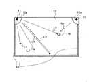
図1は、第1の例の座標検出装置を説明するための座標検出装置の上面図である。図示した構成の角度検出手段は、指や指示棒などの指示手段15によって座標が入力される座標入力面となるパネル13と、発光手段および発光手段が発した光の反射光を受光できる位置に設けられた受光手段である受発光部12a、12bと、受発光部12a、12bが発光した光を再帰的に反射する反射手段である再帰性反射部材14と、再帰性反射部材14で反射された反射光を受発光部12a、12bへの入射角度に応じて受発光部12a、12bの異なる位置に受光させる光学手段である集光レンズ50(図3〜図5)とを有している。
【0038】
なお、第1の例の座標入力装置のパネル13は、略四角形の形状を有し、電子的に画像を表示するディスプレイやマーカーなどを用いて書き込みが可能なホワイトボードであっても良い。
【0039】
受発光部12aに内蔵される光源11が照射した光は、L1、L2、…Lnを光軸とする光束として座標入力面の全域に扇状に広がっていく。このような光束のうち、例えば、光軸L3に注目した場合、光軸L3の光束の反射光(光軸L3’)は、再帰性の再帰性反射部材14で反射されて光軸L3と同じ光軸を通って受発光部12aに向かう。受発光部12aには、後述する受光手段が設けてあって、この反射光を受光する。このような受光手段は、光軸L1、L2、…Lnで表される光束のすべてについてその反射光を受光できるように構成されている。
【0040】
パネル13内の一点にオペレータが指やペンといった指示手段15を置いて座標を入力すると、光軸L1、L2、…Lnを含む光束のうちの一部が指示手段15によって遮蔽され、再帰性反射部材14に届かなくなる。このため、指示手段15によって遮られた光束の反射光が受光手段12aで受光されなくなり、受光されなかった光束から指示手段15が置かれた点、すなわち入力した座標を通る光の光軸が識別できる。
【0041】
同様にして、受発光部12bの光源11から発光した光束についてもその反射光を受光し、指示手段15が入力した座標を通る光軸を識別することができる。図1では、受発光部12aから発光した光軸Ln、12bから発光した光軸Rnが指示手段15によって入力された座標を通る光軸となっている。指示手段15の座標は、このような光軸Ln、光軸Rnの交点として算出することができる。
【0042】
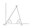
このとき、第1の例の座標入力装置では、図2のように、指示手段15が指示した指示点(入力した座標)とパネル13上の基準点(光源11の中心点)とを結ぶ直線を特定し、この直線とパネル13上の基準線(光源11の基準点同士を結ぶ直線とする)となす角度θL、角度θRを検出することによって入力された座標を通る光軸Ln、光軸Rnを検出している。そして、後述するように、角度θL、角度θRと、パネル13上の基準線の長さW(受発光部12a、12bの取り付け間隔とする)とを用いて指示手段15の座標を検出している。
【0043】
次に、上述した角度θL、角度θRを求めるための具体的な演算について説明するため、受発光部12a、受発光部12bの構成と、遮蔽された光の光軸を求める機構について説明する。なお、受発光部12a、12bは、同様に構成されている。このため、ここでは、受発光部12aに関する構成だけを図示し、受発光部12bに関する説明を略すものとする。
【0044】
図3は、受発光部12aの構成の概略を示す図で、パネル13に垂直方向から受発光部12aを見た図である。受発光部12aは、概略して光源11、集光レンズ50、受光素子51で構成されている。光源11は、受光素子51と反対側に扇状の光を照射するもので、扇状の光は、矢印53、矢印54、矢印58、矢印59の方向に照射、あるいは反射されてくる光束の集合であると考える。矢印53の方向に照射された光は、反射部材で矢印54の方向に反射されてくる。そして、集光レンズ50通って進み、受光素子51上の点51bの位置で受光される。また、矢印58の方向に照射された光は、反射部材で矢印59の方向に反射され、受光素子51上の点51aの位置で受光される。
【0045】
このように、光源11から照射され、再帰性の反射部材で反射された光の光軸とその受光位置とは、一対一の関係にある。このことから、受光素子51上の受光強度分布を調べれば、遮蔽された光がどの光軸を通って照射、あるいは反射されてきたものか分かる。そして、このような光軸を受発光部12a、受発光部12bの両方について求めれば、指示手段15によって入力された点で交わる2直線を求めることができる。
【0046】
なお、第2の例の座標入力装置では、受光素子51にCCDラインセンサを用い、受光素子51上の受光強度分布を表す信号を外部に出力するものとする。そして、本明細書中では、以降、受光素子51が出力する受光素子51上の受光強度分布を表す信号を、光強度分布信号と記すものとする。
【0047】
図4は、受光素子51上の受光強度と遮蔽された光の光軸との関係を説明する図である。図4では、集光レンズ50の中心が光源11に一致するように集光レンズ50を配置する。光源11から照射された光は、再帰性反射部材14で再帰的に反射され、集光レンズ50の中心を通って受光素子51上で受光される。このとき、受光素子51上の強度分布は、光を遮蔽するものが座標入力面上に無ければほぼ均一になる。しかし、図中に示した指示手段15で光が遮蔽された場合、受光素子51上でこ指示手段15を通る光の受光位置の受光強度が弱まることになる。なお、このような受光強度が弱い受光素子51上の点を以降暗点という。
【0048】
図4中に、受光素子51中心点を基準とした暗点の位置Dn(以降、ディップ位置ともいう)を示す。このDnは、暗点を通る直線と受光素子51の中心点を通る直線とがなす角度θnと以下の式(1)で表される対応関係がある。
θn=arctan(Dn/f) …(1)
ただし、式(1)中のfは、図4に示すように、集光レンズ50中心と受光素子51表面との距離である。
【0049】
ここで、図2で示した角度θLは、以下に示す式(2)のように、角度θLを持つ直線Lと受光素子51の中心および集光レンズ50の中心を通る直線がなす角度θnLの関数で表される。
θL=g(θnL) …(2)
ただし、
θnL=arctan(DnL/f) …(3)
式(2)、式(3)の関係は、受発光部12bについても同様に成り立つ。したがって、受発光部側のθnをθnRとし、図2のθRを表すと、
θR=h(θnR) …(4)
ただし、
θnR=arctan(DnL/f) …(5)
が得られる。
【0050】
ここで、図2中のoを原点とする点Pの座標P(x,y)は、
x=W・tanθR/(tanθL+tanθR) …(6)
y=W・tanθL・tanθR/(tanθL+tanθR) …(7)
と表すことができる。
以上のように、受発光部12a、12bに設けられる受光素子51上の暗点を検出し、この暗点と受光素子51の中心からの距離を求めることにより、指示手段15が入力した座標を検出することができる。
【0051】
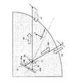
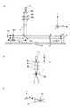
図5は、図3に示した受発光部12aの光学系を、より詳しく説明するための図で、図5(a)は、受発光部12aの発光、受光の構成を説明するための模式図、(b)は、(a)の模式図の発光に係る構成を示す図、(c)は、(a)の受光に係る構成を説明する図である。受発光部12aは、図5(a)、(b)、(c)に示した受光、発光の構成が一体的に組み込まれて構成されている。なお、図5(a)〜(c)は、いずれもそれぞれの図中に示す座標軸に従う方向から見たものとする。
【0052】
受発光部12aの光源11には、レーザダイオードやピンポイントLEDなど、ある程度、径を絞ったスポット光を生成できる光源が用いられる。光源11からパネル13に対して垂直に発した光は、シリンドリカルレンズ84によってx方向にのみコリメートされる。そして、さらにシリンドリカルレンズ85、シリンドリカルレンズ86で図中y方向に集光される。このようなシリンドリカルレンズ84とシリンドリカルレンズ85、シリンドリカルレンズ86とは、その曲率分布が互いに直交している。3枚のシリンドリカルレンズを通過してきた光は、集光部cで線状に集光する。この集光部cは、前述した座標検出原理の光源に相当することから、以降、二次光源ともいうものとする。
【0053】
また、シリンドリカルレンズ84、シリンドリカルレンズ85、シリンドリカルレンズ86でなるビーム整形レンズ群から光を取り出す取出口には図示しないスリットが設けてあって、スリットから二次光源cの光が座標入力面に向けて照射される。この照射光は、ハーフミラー87によって折り返されてパネル13の正面の側から見て扇状に広がる(図5(b))。このとき、照射光は、シリンドリカルレンズ84でコリメートされていることにより、座標入力面の垂直方向には広がらず、座標入力面に平行な光となる。
【0054】
パネル13上に広がった光は、再帰性反射部材14で反射され、出射されたときと同じ光軸を通ってビーム整形レンズ群に向かって進む(矢印Cの方向)。そして、ハーフミラー87を透過した後に集光レンズ50を通ってCCDラインセンサである受光素子51に受光される。このとき、パネル13上に指示手段15があれば、この指示手段15が光の遮蔽物となって受光素子51のいずれかのCCD撮像素子に暗点を生じる。この暗点となったCCD撮像素子の受光素子51上における位置から前述した式(2)のDnが求められ、このDnに基づいて指示手段15が入力した座標が算出できる(図5(c))。
【0055】
▲2▼ 第2の例
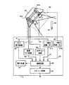
図6は、第2の例の座標検出装置を説明するための図である。図示した構成は、画像入力手段としての赤外線位置検出部61と、コントロール部71と、指示手段であるペン64とよりなっている。赤外線位置検出部61は、座標入力範囲(座標入力面)80の略全域を取り込むことが可能であって、間隔Lを隔てて配置される2つの赤外線CCDカメラ62a、62bを有している。また、ペン64の先端には、赤外線LED63が設けられている。
【0056】
コントロール部71は、赤外線CCDカメラ62a、62bをリセットするリセット信号aを生成するリセット信号回路60、赤外線CCDカメラ62a、62bを垂直走査するための垂直クロック信号bを生成する垂直クロック回路65、赤外線CCDカメラ62a、62bを水平走査するための水平クロック信号cを生成する水平クロック回路66を有している。なお、リセット信号a、垂直クロック信号b、水平クロック信号cは、赤外線CCDカメラ62a、62bに入力し、赤外線CCDカメラ62a、62bにX−Y方向の走査を開始させる信号である。
【0057】
また、コントロール部71は、赤外線CCDカメラ62a、62bが出力する映像信号d1、d2のピークを検出してピーク検出信号e1、e2を出力するピーク検出回路67a、67bと、ペン64が入力した座標を算出する演算回路68と、演算回路によって算出された座標を外部機器に出力するためのインターフェース回路69および表示するための表示回路70とを有している。また、図示した座標検出装置は、赤外線検出部61の画像取り込み範囲外にペン64が座標入力すると、警告音などを発生する音声回路部(図示せず)を備え、さらに操作性を向上させることができる。
【0058】
さらに、図示した座標検出装置は、赤外線CCDカメラ62a、62bにレンズ倍率調整回路または焦点距離調整回路を設けることにより、座標入力範囲80の大きさ、要求される入力精度などに応じて赤外線CCDカメラ62a、62b解像度や検出範囲を設定することができる。なお、図6の構成では、コントロール部71と赤外線検出部61とを別体としているが、コントロール部71に内蔵されている各回路を小型化することによって両者を一体化することも可能である。
【0059】
図7は、図6に示した座標入力装置で行われる各信号の処理を説明するためのタイミングチャートである。リセット信号a、垂直クロック信号b、水平クロック信号cは、それぞれ図示したタイミングで赤外線CCDカメラ62aと62bとに同時に入力する。リセット信号a、垂直クロック信号b、水平クロック信号cの入力により、赤外線位置検出部61は、赤外線CCDカメラ62a、62bから出力される映像信号d1、d2をコントロール部71に入力する。
【0060】
映像信号d1、d2は、赤外線CCDカメラ62a、62bでペン64を撮影した映像を表す信号である。このとき、赤外線CCDカメラ62a、62bの露出が絞られていることにより、赤外線CCDカメラ62a、62bには、赤外線LED63だけが示されてそれ以外の部分は黒色の画像が撮影される。したがって、赤外線CCDカメラ62a、62bから出力される映像信号d1、d2には、赤外線LED63の位置に相当する強いピーク信号p1、p2が表れる。
【0061】
ピーク検出回路67a、67bは、ピーク信号p1、p2を検出し、ピーク信号q1、q2を持つピーク検出信号e1、e2を出力する。このピーク検出信号e1、e2は、演算回路68に送出される。演算回路68には、図示しないROMが内蔵されていて、このROMには、ピーク検出信号e1、e2に表れたピーク信号q1、q2を赤外線LED63の位置を角度で表す角度データにそれぞれ変換する変換テーブルが記憶されている。なお、この角度データは、赤外線LED63の位置を、赤外線LED63の位置と座標入力範囲80上の基準点(例えば赤外線CCDカメラ62a、62bの原点)とを結ぶ直線を特定し、この直線と座標入力範囲80上の基準線(例えば赤外線CCDカメラ62a、62bの原点同士を結ぶ直線)とがなす角度で赤外線LED63の位置を表すものである。
【0062】
演算回路68は、以上のようにしてピーク検出信号e1、e2をそれぞれ角度に変換し、2つの角度を特定する。そして、さらに赤外線CCDカメラ62a、62b間の距離Lを用いて赤外線LED63が置かれた位置、すなわちペン64が入力した座標を算出する。このようにして得られた座標は、インターフェース回路69を介して外部の表示装置に出力される、あるいは、表示回路70に出力されて表示される。
【0063】
次に、図8を用い、角度データから入力された座標を検出する方法を具体的に説明する。なお、図8は、赤外線CCDカメラ62a、62bの一方の原点(撮影範囲の図中左下隅)を原点(0,0)とした2次元座標でペン64が入力した座標(x,y)を表したものである。
【0064】
演算回路68は、ピーク検出信号e1、e2を検出し、ここに表れたピーク信号q1、q2と、リセット信号aを基点とする垂直クロック信号b、水平クロック信号cとの関係から、赤外線CCDカメラ62aの原点を原点とした座標を用いたペン64の座標(x1,y1)および赤外線CCDカメラ62bの原点を原点とした座標を用いたペン64の座標(x2,y2)を求める。そして、この座標(x1,y1)、座標(x2,y2)を用い、図8に示した座標を用いて赤外線CCDカメラ62a、62bから見たペン64の位置を角度θL、θRで表せば、以下のようになる。
θL=tan-1(y1/x1) …式(8)
θR=tan-1(y2/x2) …式(9)
【0065】
次に、上記した式(8)、式(9)から角度θL、θRを求め、さらに赤外線CCDカメラ62a、62b間の距離Lを用いれば、図8に示した座標で表されるペン64が入力した座標(x,y)は、以下の式によって求められる。
y=xtanθL …式(10)
y=(x−L)tan(π−θR) …式(11)
【0066】
上記した式(10)、(11)を連立一次方程式としてx、yを求めれば、ペン64が入力した座標(x,y)が算出できる。先に述べた演算回路68の変換テーブルは、このような処理をより高速に行うために予め演算した結果を(x1,y1)、(x2,y2)と関連づけて記憶しておくものである。また、このような第2の例の座標検出装置は、タブレット盤などを作業台に置く必要がなく、作業スペースを有効に利用することができる。また、座標入力範囲80に原稿などが重ねて置かれている場合にも座標入力装置に対する座標入力が可能になる。さらに、レンズ倍率変調回路部などによって赤外線CCDカメラ62a、62bの画像取り込み範囲を可変設定でき、これと共に解像度をも設定できるので、座標入力装置の操作性、利便性をも高めることができる。
【0067】
(実施の形態1)
図9は、本発明の実施の形態1を説明するためのブロック図である。また、図10は、図9に示した構成で行われる座標検出の処理を説明するための図であって、後述する角度検出部4a、4bが備える受光素子51a、受光素子51bが検出したディップ位置と検出の周期との関係を示す図である。なお、本発明の実施の形態の座標入力装置は、いずれも先に述べた座標入力装置のうち、第1の例の座標入力装置として構成したものとする。
【0068】
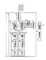
実施の形態1の座標入力装置は、指などの指示手段15(図1)によって座標が入力される座標入力面であるパネル13(図1)と、入力された座標の検出を実行する座標検出実行部6と、座標検出実行部6を制御する中央処理装置7とを有している。座標検出実行部6は、入力した光強度分布信号に基づいて、指示手段15がパネル13上に入力した座標とパネル13上の基準点とを結ぶ直線とパネル13上の基準線とがなす角度を周期的に検出する角度検出手段である少なくとも2つの角度検出部4a、4bと、角度検出部4a、4bに検出された角度のうち、直前の周期で検出された角度を記憶する角度記憶手段である角度記憶部99と、角度検出部4a、4bが周期的に検出した角度の個数が前回の検出時よりも今回の検出時に多かった場合、角度記憶部99に記憶されている角度データに最も近いデータを今回検出した角度データから選択する角度選択手段である角度選択部5と、角度選択部5が選択した角度に基づいて、指示手段15が入力した座標を検出する座標検出手段である座標演算部95とを有している。
【0069】
実施の形態1の角度検出部4a、4bは、指示手段15を撮像して光強度分布信号として出力する受光素子51a、51bをそれぞれ有している。受光素子51a、51bは、周期的に座標検出実行部6に光強度分布信号を入力する。また、実施の形態1の角度検出部4a、4bは、受光素子51a、51bが受光した光に基づいて光強度分布信号を生成し、それぞれ、光強度分布信号からディップ位置を検出するディップ位置検出部93a、93bと、さらに角度に変換する角度変換部94a、94bとを有している。また、角度選択部5は、最近接角度選択部97と、最近接角度以外選択部98を有している。
【0070】
さらに、座標演算部95は、角度検出部4a、4bが周期的に検出した角度の個数が前回の検出時よりも今回の検出時に各角度検出部4a、4bについて1個ずつ多かった場合、角度選択部5によって選択されなかった角度に基づいて、他の指示手段が入力した座標を検出するよう構成されている。
【0071】
一方、中央処理装置7には、座標検出実行部6に含まれる各構成を制御するプログラムが記録された、例えばフロッピーディスクなどの記録媒体10がセットされている。中央処理装置7は、この記録媒体10に記録されているプログラムを読み出し、この内容にしたがって座標検出実行部6の各構成を制御する。なお、記録媒体10として差し替え可能なフロッピーディスクなどを用いることには、パソコンなどの汎用的な機器を中央処理装置7として使用することが可能になるという利点がある。
【0072】
次に、図10を用いて図9に示した構成で行われる処理について説明する。ディップ位置検出部93a、93bは、図3で説明した方法によってディップ位置を算出する。ディップ位置は、指示手段15がパネル13上で指示した指示点とパネル13上の基準点とを結ぶ直線とパネル13上の基準線とがなす角度に角度変換部で変換される。ここでディップ位置を角度に変換する理由は、後に座標演算部95において、式(1)〜式(7)を使って座標を算出するためである。なお、実施の形態1では、図2で示したように、パネル13上の基準点を受発光部12a、12bに内蔵される光源11の中心点、受発光部12a、12bに内蔵される光源11の中心点同士を結んだ線を基準線とする。
【0073】
図10は、受光素子51aに周期的に検出される光強度分布信号(図中Lで示す)と、受光素子51bに周期的に検出される光強度分布信号(図中Rで示す)とを、検出の周期i−1、i、i+1について示した図である。図中、縦軸は光強度分布信号の光強度を、また、横軸は、受光素子51a、51b上のディップ位置を示している。
【0074】
図示したように、周期i−1で受光素子51a、51bからディップ位置検出部93a、93bに入力した光強度分布信号には、L、Rのいずれにもピークがなく、パネル13への座標入力が行われていない。このとき、ディップ位置検出部93a、93bは、「ディップなし」を示す信号nullを発生して角度変換部94a、94bに入力する。
【0075】
角度変換部94a、94bでは、信号nullを受け取って同じく信号nullを発生する。さらに、この信号nullを受け取った角度選択部5でも信号nullを発生し、座標演算部95に出力する。座標演算部95は、信号nullを入力すると信号nullを出力するか、あるいは何の信号も出力しない。また、角度選択部5で発生した信号nullは、角度記憶部99にも入力して記憶される。
【0076】
次に、周期iの検出では、受光素子51aからディップ位置検出部93aに入力した光強度分布信号Lにディップを表す信号(ディップ信号)Aが現れている。また、受光素子51bからディップ位置検出部93bに入力した光強度分布信号Rには、ディップ信号Bが現れている。ディップ信号A、ディップ信号Bは、受光素子51a、51bに入力し、ディップ位置検出部93a、93bでディップ位置を検出された後に角度変換部94a、94bでそれぞれ角度θL、θRに変換される。このとき、角度θL、θRは、組み合わされたデータ(θL,θR)(角度データ)として角度選択部5を介して座標演算部95に入力し、指示手段15が入力した座標に変換されて出力される。また、ディップ信号Aおよびこれに基づく(θL,θR)の角度データは、角度記憶部99にも出力されて先に記憶されていた信号nullに上書きされる。
【0077】
次に、周期i+1の検出では、受光素子51aからディップ位置検出部93aに入力した光強度分布信号Lにディップ信号A1とディップ信号A2とが現れている。受光素子51bからディップ位置検出部93bに入力した光強度分布信号Rには、ディップ信号B1とディップ信号B2とが現れている。このような状態は、周期iで検出された指示手段15の他、他の指示手段による入力がなされた場合に生じるものである。
【0078】
このような場合、ディップ信号A1、A2、ディップ信号B1、B2は、ディップ位置検出部93a、93bでディップ位置を検出された後に角度変換部94a、94bでそれぞれ角度θL1、θL2、θR1、θR2に変換される。そして、角度選択部5に入力し、ここで入力された座標を正しく表すように組み合わされた角度データとなる。
【0079】
すなわち、角度選択部5では、角度θL1、θL2、θR1、θR2を最近接角度選択部97および最近接角度以外選択部98に出力する。最近接角度選択部97、最近接角度以外選択部98は、角度記憶部99に記憶されている角度データ(θL、θR)を読み出し、角度θLを、角度θL1、角度θL2と比較する。また、角度θRを、角度θR1、角度θR2と比較する。次に、この比較についてより具体的に説明する。ただし、角度θLと角度θL1、角度θL2との比較、角度θRと角度θR1、角度θR2との比較は、同様の手順で行われるため、この説明では、受光素子51aについてのみ説明するものとする。
【0080】
角度θLと角度θL1、角度θL2との比較は、例えば、図10に示したように、角度記憶部99に記憶されているθLのディップ位置Dと今回検出された角度θL1(ディップ信号A1)のディップ位置D1の差d1をとり、さらにθLのディップ位置Dと今回検出された角度θL2(ディップ信号A2)のディップ位置D2の差d2をとり、d1、d2を比較することによって行われる。
【0081】
そして、最近接角度選択部97では、ディップ位置Dとの差が小さい方のディップ信号A1、およびディップ信号A1を変換した角度θL1を採用し、座標演算部95に出力すると共に角度記憶部99にも出力する。このとき、同様の処理によってディップ信号B1、およびディップ信号B1を変換した角度θR1が採用され、座標演算部95に出力されると共に角度記憶部99にも出力される。
【0082】
角度記憶部99では、角度θL1と角度θR1から角度データ(θL1、θR1)を作成して角度データ(θL、θR)に上書きする。また、座標演算部95は、入力した角度θL1と角度θR1とに基づいて演算を行い、角度データ(θL1、θR1)で表される指示手段15によって入力された座標(x1,y1)を検出する。なお、以上の構成では、受光素子51a、51bに光強度分布信号が発生してから座標演算部95が出力されるまでの処理を周期tで繰り返し行っている。
【0083】
なお、上記したディップ信号および角度の選択は、受発光部12a、12bによる検出が1/30秒と比較的速い周期で行われることから、連続する周期で検出される座標間のずれはわずかなものであるとしてなされるものである。そして、先に検出された座標から比較的大きくずれて入力された座標は、他の指示手段によって入力された座標であると考える。
【0084】
また、図10に示したように、前回の検出と今回の検出とで増加した角度の個数は、角度検出部4a、4bについてそれぞれ1個ずつであり、採用されなかった角度が形成し得る角度データは、1つだけである。このような場合、角度選択部5の最近接角度以外選択部98は、採用されなかった角度θL2、角度θR2を用いて角度データ(θL2、θR2)を作成して座標演算部95に出力する。座標演算部95では、角度データ(θL2、θR2)についても座標を検出し、他の指示手段によって入力された座標(x2,y2)として出力する。
【0085】
また、実施の形態1の座標入力装置は、さらに、角度検出部4a、4bによって周期的に検出される角度が、前回の検出時よりも今回の検出時に角度検出部4a、4bのいずれかについて2個以上多かった場合、角度選択部5によって選択されなかった角度を棄却する角度棄却手段である棄却選択部を設けるよう構成することができる。
【0086】
図11は、棄却選択部120を備えた実施の形態1の座標入力装置を説明するためのブロック図である。なお、図示した座標入力装置のうち、図9で説明した座標入力装置と同様の構成については同じ符号を付し、説明を略すものとする。図11に示した座標入力装置の座標検出実行部126は、最近接角度選択部97、最近接角度以外選択部98の他、棄却選択部120を有する角度選択部125を有している。そして、座標検出実行部126を制御する中央処理装置7は、記録媒体10が記録しているプログラムに加えて棄却選択部120を制御するプログラムを記録した記録媒体121を有している。
【0087】
次に、棄却選択部120で行われる処理について説明する。図12は、受光素子51aに周期的に検出される光強度分布信号(図中Lで示す)と、受光素子51bに周期的に検出される光強度分布信号(図中Rで示す)とを、検出の周期i、i+1について示した図である。図中、縦軸は光強度分布信号の光強度を、また、横軸は、受光素子51a、51b上のディップ位置を示している。
【0088】
図12に示した周期iの検出では、受光素子51aからディップ位置検出部93aに入力した光強度分布信号Lにディップを表すディップ信号Aが現れている。また、受光素子51bからディップ位置検出部93bに入力した光強度分布信号Rには、ディップ信号Bが現れている。ディップ信号A、ディップ信号Bは、受光素子51a、51bに入力し、ディップ位置検出部93a、93bでディップ位置を検出された後に角度変換部94a、94bでそれぞれ角度θL、θRに変換される。このとき、角度θL、θRは、角度データ(θL,θR)として角度選択部125を介して座標演算部95に入力し、指示手段15が入力した座標に変換されて出力される。また、ディップ信号Aおよびこれに基づく(θL,θR)の角度データは、角度記憶部99にも出力されて記憶される。
【0089】
次に、周期i+1の検出では、受光素子51aからディップ位置検出部93aに入力した光強度分布信号Lにディップ信号A1と、ディップ信号A2と、ディップ信号A3とが現れている。そして、受光素子51bからディップ位置検出部93bに入力した光強度分布信号Rには、ディップ信号B1と、ディップ信号B2と、ディップ信号B3とが現れている。
【0090】
ディップ信号A1、A2、A3、ディップ信号B1、B2、B3は、ディップ位置検出部93a、93bでディップ位置を検出された後に角度変換部94a、94bでそれぞれ角度θL1、θL2、θL3およびθR1、θR2、θR3に変換される。そして、角度θL1、θL2、θL3およびθR1、θR2、θR3は、角度選択部125に入力する。角度選択部125は、角度記憶部99に記憶されているθLのディップ位置Dと今回検出された角度θL1(ディップ信号A1)のディップ位置D1の差d1をとり、また、θLのディップ位置Dと今回検出された角度θL2(ディップ信号A2)のディップ位置D2の差d2をとり、さらにθLのディップ位置Dと今回検出された角度θL3(ディップ信号A3)のディップ位置D3の差d3をとり、d1、d2、d3を比較する。
【0091】
そして、最近接角度選択部97では、ディップ位置Dとの差が小さい方のディップ信号A1、およびディップ信号A1を変換した角度θL1を採用し、座標演算部95に出力すると共に角度記憶部99にも出力する。このとき、同様の処理によってディップ信号B1、およびディップ信号B1を変換した角度θR1が採用され、座標演算部95に出力されると共に角度記憶部99にも出力される。
【0092】
また、図12に示したように、前回の検出と今回の検出とで増加した角度の個数は、角度検出部4a、4bについてそれぞれ2個ずつであり、採用されなかった角度が形成し得る角度データは、4通りある。このような場合、角度選択部125は、採用されなかった角度θL2、θL3および角度θR2、θR3の正しい組み合わせを判定することができない。
【0093】
このため、角度選択部125の最近接角度以外選択部98は、採用されなかった角度θL2、θL3および角度θR2、θR3を棄却選択部120に出力する。棄却選択部120は、角度θL2、θL3および角度θR2、θR3を入力して消去する。したがって、最近接角度選択部97によって選択された角度によって作成された角度データ(θL1、θR1)に基づく座標だけが検出されることになる。
【0094】
図13は、以上述べた実施の形態1の座標入力装置で行われる処理を説明するためのフローチャートである。なお、このフローチャートは、図11に示した記録媒体121に記憶されていて、中央処理装置7によって読み出されて実行されるものである。
【0095】
図13のフローチャートは、処理が開始すると、受光素子51a、51bから光強度分布信号が入力したか否か判断する(S1)。そして、光強度分布信号の入力がない場合には(S1:No)、入力がなされるまで待機し、信号が入力すると(S1:Yes)、その信号からディップ位置を検出(S2)してディップ位置をさらに角度に変換する(S3)。角度に変換された信号は、角度選択部125において、変換した角度の個数が前回の検出時に変換した角度の個数よりも多いか否か判断される(S4)。
【0096】
ステップS4の判断で、角度の個数が増加していない場合には(S4:No)、変換した角度を組み合わせてそのまま角度データを作成して座標を演算し(S9)、出力する(S10)。一方、角度の個数が増加している場合には(S4:Yes)、角度記憶部99に記憶されている角度に最も近い最近接角度を選択する(S5)と共に角度記憶部99に上書き、記憶する(S6)。そして、増加角度数が1であるか否か判断し(S7)、増加角度数が1であった場合には(S7:Yes)、最近接角度以外の角度を選択して角度データを作成し(S8)、最近接角度から作成された角度データと共にこの角度データからも座標を演算して(S9)出力する(S10)。
【0097】
一方、増加角度数が1でなかった(つまり、1より大きい)場合には(S7:No)、最近接角度以外を棄却する(S11)。この場合には、最近接角度から作成された角度データだけから座標を演算して(S9)出力し(S10)、すべての処理を終了する。
【0098】
以上述べた実施の形態1の座標入力装置は、複数の座標が入力された場合、この座標を2つの指示手段ごとに判別でき、複数の操作者による座標入力が可能な座標入力装置を提供することができる。また、実施の形態1の座標入力装置は、複数の座標が入力された場合、この座標から1つの指示手段によって入力された座標を他の指示手段による影響を受けることなく判別できる。
【0099】
さらに実施の形態1は、中央処理装置によって読み出される座標入力装置の記録媒体に記録されたプログラムによって座標検出実行部を制御しているから、中央処理装置として汎用的なパソコンなどを利用することができる。このため、実施の形態1は、座標入力装置を比較的安価、かつ簡便に構成することができる。
【0100】
また、本発明は、以上述べた実施の形態1に限定されるものではない。すなわち、実施の形態1では、ディップ位置を比較するにあたってディップ位置の差を演算によって求め、この差が最も小さいものを最近接角度としている。しかし、例えば、予め適切な閾値を設定しておき、複数検出された角度から、角度記憶部99に記憶されている角度とのディップ位置の差がこの閾値以下になる角度を選択するようにしても良い。
【0101】
また、実施の形態1は、先に述べた第1の例の座標入力装置として構成されているが、先に述べた第2の例の座標入力装置として構成することも可能である。なお、この場合の光強度分布信号の処理は、実施の形態1における光強度分布信号の処理の説明中、ディップ位置をピーク、ディップ信号をピーク信号と読み替えることで説明される。
【0102】
(実施の形態2)
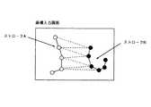
図14は、2つの指示手段によって同時に座標入力される場合の座標の軌跡を模式的に示した図である。図中に示した白丸は、指示手段Aによって入力された座標を示し、黒丸は、指示手段Bによって入力された座標を示している。したがって、このような座標をホストコンピュータのような外部機器に出力する場合には、白丸で示した座標が図中のストロークAを描き、黒丸で示した座標が図中のストロークBを描くように出力する必要がある。しかし、入力された座標を単純に入力された順序で出力すると、白丸で示した座標と黒丸で示した座標とが区別できずに図中に破線で示した軌跡を描くものとして出力される虞がある。実施の形態2は、このようなことを防ぐためになされたものである。
【0103】
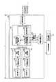
図15は、本発明の実施の形態2を説明するためのブロック図である。なお、図15に示した構成のうち、実施の形態1で説明した図9、図11と同様の構成については同様の符号を付してその説明を一部略すものとする。
【0104】
図15に示した実施の形態2の座標入力装置は、指などの指示手段15(図1)によって座標が入力される座標入力面であるパネル13(図1)と、指示手段15を撮像して光強度分布信号として出力する少なくとも2つの角度検出部4a、4bとを有している。さらに、実施の形態2の座標入力装置は、入力された座標の検出を実行する座標検出実行部156と、座標検出実行部156を制御する中央処理装置7とを有している。
【0105】
座標検出実行部156は、角度検出部4a、4b、角度選択部5、座標演算部95、角度記憶部99の他、角度選択部5によって選択された角度に第1の識別子を付すと共に、受光素子51a、受光素子51bが周期的に検出した角度の個数が前回の検出時よりも今回の検出時に受光素子51a、受光素子51bについて1個ずつ多かった場合、第1の識別子が付されなかった角度に対して第2の識別子を付す識別子付与部150を有している。
【0106】
図15に示した座標入力装置に対し、図10に示した信号が入力すると、周期i−1で入力した光強度分布信号にはL、Rのいずれにもピークがないことから、ディップ位置検出部93a、93bは、「ディップなし」を示す信号nullを発生して角度変換部94a、94bに入力する。
【0107】
角度変換部94a、94bでは、信号nullを受け取って同じく信号nullを発生する。さらに、この信号nullを受け取った角度選択部5でも信号nullを発生し、座標演算部95に出力する。座標演算部95は、信号nullを入力すると信号nullを出力するか、あるいは何の信号も出力しない。また、角度選択部5で発生した信号nullは、角度記憶部99にも入力して記憶される。
【0108】
次に、周期iの検出では、光強度分布信号L、Rに現れたディップ信号A、ディップ信号Bを受光素子51a、51bに入力する。ディップ信号A、ディップ信号Bは、ディップ位置検出部93a、93bでディップ位置を検出された後に角度変換部94a、94bでそれぞれ角度θL、θRに変換される。角度θL、θRは、角度データ(θL,θR)として角度記憶部99に出力され、先に記憶されていた信号nullに上書きされる。
【0109】
このとき、実施の形態2の座標入力装置では、識別子付与手段150によって角度データ(θL,θR)にsid(ストロークID)=1が付与される。角度データ(θL,θR)は、sid=1と共に角度記憶部99に記憶される。また、識別子付与手段150は、角度選択部5を介して座標演算部95に入力する角度データ(θL,θR)に対してもsid=1を付与する。角度データ(θL,θR)は、sid=1と共に座標演算部95に出力される。
【0110】
次に、周期i+1の検出では、光強度分布信号L、Rに現れたディップ信号A1、A2、ディップ信号B1、B2を受光素子51a、51bに入力する。ディップ信号A1、A2、ディップ信号B1、B2は、ディップ位置検出部93a、93bでディップ位置を検出された後に角度変換部94a、94bでそれぞれ角度θL1、θL2、θR1、θR2に変換される。そして、角度選択部5に入力し、ここで入力された座標を正しく表すように組み合わされた角度データとなる。
【0111】
すなわち、角度選択部5では、角度θL1、θL2、θR1、θR2を最近接角度選択部97および最近接角度以外選択部98に出力する。最近接角度選択部97、最近接角度以外選択部98は、角度記憶部99に記憶されている角度データ(θL、θR)を読み出し、角度θLを、角度θL1、角度θL2と比較する。また、角度θRを、角度θR1、角度θR2と比較する。なお、この比較は、先に図10で説明した方法度同様にして行われる。
【0112】
そして、最近接角度選択部97では、ディップ位置Dとの差が小さい方のディップ信号A1、およびディップ信号A1を変換した角度θL1を採用し、座標演算部95に出力すると共に角度記憶部99にも出力する。また、同様の処理によってディップ信号B1、およびディップ信号B1を変換した角度θR1が採用され、座標演算部95に出力されると共に角度記憶部99にも出力される。
【0113】
角度記憶部99では、角度θL1と角度θR1から角度データ(θL1、θR1)を作成して角度データ(θL、θR)に上書きする。このとき、実施の形態2の座標入力装置では、識別子付与手段150によって角度データ(θL,θR)にsid(ストロークID)=1が付与される。角度データ(θL,θR)は、sid=1と共に角度記憶部99に記憶される。また、識別子付与手段150は、角度選択部5を介して座標演算部95に入力する角度データ(θL,θR)に対してもsid=1を付与する。角度データ(θL,θR)は、sid=1と共に座標演算部95に出力される。
【0114】
座標演算部95は、入力した角度θL1と角度θR1とに基づいて演算を行い、角度データ(θL1、θR1)で表される指示手段15によって入力された座標(x1,y1)を検出する。そして、sid=1と共に外部のホストコンピュータなどに出力する。なお、以上の構成では、受光素子51a、51bに光強度分布信号が発生してから座標演算部95が出力されるまでの処理を周期tで繰り返し行っている。
【0115】
また、以上説明した実施の形態2では、前回の検出と今回の検出とで増加した角度の個数は、角度検出部4a、4bについてそれぞれ1個ずつであり、採用されなかった角度が形成し得る角度データは1つだけである。このような場合、角度選択部5の最近接角度以外選択部98は、採用されなかった角度θL2、角度θR2を用いて角度データ(θL2、θR2)を作成して座標演算部95に出力する。このとき、実施の形態2の座標入力装置では、識別子付与手段150によって角度データ(θL2,θR2)にsid=2が付与される。座標演算部95では、角度データ(θL2、θR2)についても座標を検出し、他の指示手段によって入力された座標(x2,y2)としてsid=2と共に出力する。
【0116】
sid=1が付与されて出力した座標(x1,y1)、sid=2が付与されて出力した座標(x2,y2)は、例えばホストコンピュータに入力する。ホストコンピュータでは、座標入力装置側の検出の周期に応じて連続して入力されてくる座標(x1,y1)、座標(x2,y2)を、それぞれの識別子で分類し、同じ識別子が付された座標同士が入力順に連続して表示装置に表示されるように処理する。この結果、図14に示したように、識別子sid=1が付された座標がストロークAを描き、識別子sid=2が付された座標がストロークBを描くようになる。
【0117】
また、実施の形態1の座標入力装置は、さらに、角度検出部4a、4bによって周期的に検出される角度が、前回の検出時よりも今回の検出時に角度検出部4a、4bのいずれかについて2個以上多かった場合、角度選択部5によって選択されなかった角度を棄却する角度棄却手段である棄却選択部120を設けるよう構成することができる。
【0118】
図16は、棄却選択部120が設けられた本発明の実施の形態2を説明するためのブロック図である。また、図17は、図16に示した構成で行われる座標検出の処理を説明するためのフローチャートである。なお、図17に示した構成のうち、先に説明した図9、図11、図15で示した構成と同様の構成については同じ符号を付し、その説明を略すものとする。
【0119】
図16に示した座標入力装置の座標検出実行部166は、最近接角度選択部97、最近接角度以外選択部98の他、棄却選択部120を有する角度選択部125を有している。そして、座標検出実行部126を制御する中央処理装置7は、記録媒体151が記録しているプログラムに加えて棄却選択部120を制御するプログラムを記録した記録媒体161を有している。
【0120】
次に、棄却選択部120で行われる処理について説明する。座標検出実行部126に図12で示した光強度分布信号が入力すると、周期iの検出では、ディップ信号A、ディップ信号Bは、受光素子51a、51bに入力し、ディップ位置検出部93a、93bでディップ位置を検出された後に角度変換部94a、94bでそれぞれ角度θL、θRに変換される。このとき、角度θL、θRは、角度データ(θL,θR)として角度選択部125を介して座標演算部95に入力し、指示手段15が入力した座標に変換されて出力される。また、ディップ信号Aおよびこれに基づく(θL,θR)の角度データは、角度記憶部99にも出力されて記憶される。
【0121】
次に、周期i+1の検出では、ディップ信号A1、A2、A3、ディップ信号B1、B2、B3は、ディップ位置検出部93a、93bでディップ位置を検出された後に角度変換部94a、94bでそれぞれ角度θL1、θL2、θL3およびθR1、θR2、θR3に変換される。そして、角度θL1、θL2、θL3およびθR1、θR2、θR3は、角度選択部125に入力し、角度選択部125は、角度記憶部99に記憶されているθLのディップ位置Dと今回検出された角度θL1(ディップ信号A1)のディップ位置D1の差d1をとり、また、θLのディップ位置Dと今回検出された角度θL2(ディップ信号A2)のディップ位置D2の差d2をとり、さらにθLのディップ位置Dと今回検出された角度θL3(ディップ信号A3)のディップ位置D3の差d3をとり、d1、d2、d3を比較する。
【0122】
そして、最近接角度選択部97では、ディップ位置Dとの差が小さい方のディップ信号A1、およびディップ信号A1を変換した角度θL1を採用し、座標演算部95に出力すると共に角度記憶部99にも出力する。このとき、同様の処理によってディップ信号B1、およびディップ信号B1を変換した角度θR1が採用され、第1の識別子が識別子付与部150によって付与されて座標演算部95に出力されると共に角度記憶部99にも出力される。
【0123】
また、図12に示したように、前回の検出と今回の検出とで増加した角度の個数は、角度検出部4a、4bについてそれぞれ2個ずつであり、採用されなかった角度が形成し得る角度データは、4通りある。このような場合、角度選択部125は、採用されなかった角度θL2、θL3および角度θR2、θR3の正しい組み合わせを判定することができない。
【0124】
このため、角度選択部125の最近接角度以外選択部98は、採用されなかった角度θL2、θL3および角度θR2、θR3を棄却選択部120に出力する。棄却選択部120は、角度θL2、θL3および角度θR2、θR3を入力して消去する。したがって、最近接角度選択部97によって選択された角度によって作成された角度データ(θL1、θR1)に基づく座標だけが検出され、ストロークAだけが表示装置に表示されることになる。
【0125】
次に、以上述べた実施の形態1の座標入力装置で行われる処理を図17のフローチャートを用いて説明する。なお、このフローチャートは、図16に示した記録媒体161に記憶されていて、中央処理装置7によって読み出されて実行されるものである。
【0126】
図17のフローチャートは、処理が開始すると、受光素子51a、51bから光強度分布信号が入力したか否か判断する(S21)。そして、光強度分布信号の入力がない場合には(S21:No)、入力がなされるまで待機し、信号が入力すると(S21:Yes)、その信号からディップ位置を検出(S22)してディップ位置をさらに角度に変換する(S23)。角度に変換された信号は、角度選択部125において、変換した角度の個数が前回の検出時に変換した角度の個数よりも多いか否か判断される(S24)。
【0127】
ステップS24の判断で、角度の個数が増加していない場合には(S24:No)、変換した角度を組み合わせてそのまま角度データを作成して座標を演算し(S31)、出力する(S32)。一方、角度の個数が増加している場合には(S24:Yes)、角度記憶部99に記憶されている角度に最も近い最近接角度を選択する(S25)。そして、第1識別子、すなわちsid=1を付与して(S26)角度記憶部99に上書き、記憶する(S27)。角度選択部125は、次に増加角度数が1であるか否か判断し(S28)、増加角度数が1であった場合には(S28:Yes)、最近接角度以外の角度を選択して角度データを作成し(S29)、第2識別子を付与して(S30)、最近接角度から作成された角度データと共にこの角度データからも座標を演算して(S31)出力する(S32)。
【0128】
一方、増加角度数が1でなかった(つまり、1より大きい)場合には(S28:No)、最近接角度以外を棄却する(S33)。この場合には、最近接角度から作成された角度データだけから座標を演算して(S31)出力し(S32)、すべての処理を終了する。
【0129】
以上述べた実施の形態2は、複数の座標が入力された場合、この座標から2つの指示手段によって入力された座標のストロークをそれぞれ判別でき、複数の操作者による座標入力が可能な座標入力装置を提供することができる。また、実施の形態2は、複数の座標が入力された場合、この座標から1つの指示手段によって入力された座標のストロークを他の指示手段による影響を受けることなく判別できる座標入力装置を提供することができる。
【0130】
さらに実施の形態2は、中央処理装置によって読み出される座標入力装置の記録媒体に記録されたプログラムによって座標検出実行部を制御しているから、中央処理装置として汎用的なパソコンなどを利用することができる。このため、実施の形態2は、座標入力装置を比較的安価、かつ簡便に構成することができる。
【0131】
また、本発明は、以上述べた実施の形態2に限定されるものではない。すなわち、実施の形態2では、ディップ位置を比較するにあたってディップ位置の差を演算によって求め、この差が最も小さいものを最近接角度としている。しかし、例えば、予め適切な閾値を設定しておき、複数検出された角度から、角度記憶部99に記憶されている角度とのディップ位置の差がこの閾値以下になる角度を選択するようにしても良い。
【0132】
また、実施の形態2は、先に述べた第1の例の座標入力装置として構成されているが、先に述べた第2の例の座標入力装置として構成することも可能である。なお、この場合の光強度分布信号の処理は、実施の形態2における光強度分布信号の処理の説明中、ディップ位置をピーク、ディップ信号をピーク信号と読み替えることで説明される。
【発明の効果】
以上説明した本発明は、以下の効果を奏することができる。すなわち、
請求項1記載の発明は、前回座標を検出した指示手段によって指示された指示点と、他の1つの指示手段によって指示された点とを判別して座標を検出できる。したがって、請求項1記載の発明は、複数の座標が入力された場合、この座標から2つの指示手段によって入力された座標を2つの指示手段ごとに判別でき、複数の操作者による座標入力が可能な座標入力装置を提供することができる。
【0134】
請求項2記載の発明は、前回座標を検出した指示手段によって指示された指示点だけを判別して座標を検出できる。したがって、請求項2記載の発明は、複数の座標が入力された場合、この座標から1つの指示手段によって入力された座標を他の指示手段による影響を受けることなく判別できる座標入力装置を提供することができる。
【0135】
請求項3記載の発明は、前回座標を検出した指示手段によるストロークと、追加された指示手段によるストロークを判別して座標を検出できる。したがって、請求項3記載の発明は、複数の座標が入力された場合、この座標から2つの指示手段によって入力された座標のストロークをそれぞれ判別でき、複数の操作者による座標入力が可能な座標入力装置を提供することができる。
【0137】
請求項4記載の発明は、前回座標を検出した指示手段によるストロークだけを判別することができる。したがって、請求項4記載の発明は、複数の座標が入力された場合、この座標から1つの指示手段によって入力された座標のストロークを他の指示手段による影響を受けることなく判別できる座標入力装置を提供することができる。
【0138】
請求項5記載の発明は、指示手段を比較的簡易な構成とすることができ、また、座標入力面を比較的広くできるため、簡易かつ操作性の高い座標入力装置を構成することができる。
【0139】
請求項6記載の発明は、指示手段を比較的簡易な構成とすることができ、また、座標入力面を比較的広くできるため、簡易かつ操作性の高い座標入力装置を構成することができる。
【0140】
請求項7記載の発明は、前回座標を検出した指示手段によって指示された指示点と、他の1つの指示手段によって指示された点とを判別して座標を検出できる。したがって、請求項7記載の発明は、複数の座標が入力された場合、この座標から2つの指示手段ごとに判別でき、複数の操作者による座標入力が可能な座標入力装置の記録媒体を提供することができる。また、このような処理を行う中央処理装置に汎用的な機器を適用することを可能にする。
【0142】
請求項8記載の発明は、前回座標を検出した指示手段によって指示された指示点だけを判別して座標を検出できる。したがって、請求項8記載の発明は、複数の座標が入力された場合、この座標から1つの指示手段によって入力された座標を他の指示手段による影響を受けることなく判別できる座標入力装置の記録媒体を提供することができる。また、このような処理を行う中央処理装置に汎用的な機器を適用することを可能にする。
【0143】
請求項9記載の発明は、前回座標を検出した指示手段によるストロークと、追加された指示手段によるストロークを判別して座標を検出できる。したがって、請求項9記載の発明は、複数の座標が入力された場合、この座標から2つの指示手段によって入力された座標のストロークをそれぞれ判別でき、複数の操作者による座標入力が可能な座標入力装置の記録媒体を提供することができる。また、このような処理を行う中央処理装置に汎用的な機器を適用することを可能にする。
【0145】
請求項10記載の発明は、前回座標を検出した指示手段によるストロークだけを判別することができる。したがって、請求項10記載の発明は、複数の座標が入力された場合、この座標から1つの指示手段によって入力された座標のストロークを他の指示手段による影響を受けることなく判別できる座標入力装置の記録媒体を提供することができる。また、このような処理を行う中央処理装置に汎用的な機器を適用することを可能にする。
【図面の簡単な説明】
【図1】本発明に適用される座標入力装置の第1の例を説明するための図である。
【図2】本発明に適用される座標入力装置の第1の例を説明するための他の図である。
【図3】本発明に適用される座標入力装置の第1の例を説明するための他の図である。
【図4】本発明に適用される座標入力装置の第1の例を説明するための他の図である。
【図5】本発明に適用される座標入力装置の第1の例を説明するための他の図である。
【図6】本発明に適用される座標入力装置の第2の例を説明するための図である。
【図7】本発明に適用される座標入力装置の第2の例を説明するための他の図である。
【図8】本発明に適用される座標入力装置の第2の例を説明するための他の図である。
【図9】本発明の実施の形態1の座標入力装置を説明するためのブロック図である。
【図10】本発明の実施の形態1、実施の形態2の座標入力装置で処理される信号を説明するための図である。
【図11】本発明の実施の形態1の他の例の座標入力装置を説明するためのブロック図である。
【図12】本発明の実施の形態1、実施の形態2の座標入力装置で処理される信号を説明するための他の図である。
【図13】本発明の実施の形態1の座標入力装置で行われる処理を説明するフローチャートである。
【図14】本発明の実施の形態2の座標入力装置の機能を説明するための図である。
【図15】本発明の実施の形態2の座標入力装置を説明するためのブロック図である。
【図16】本発明の実施の形態2の座標入力装置の他の例を説明するためのブロック図である。
【図17】本発明の実施の形態2の座標入力装置で行われる処理を説明するフローチャートである。
【図18】従来の座標入力装置を説明するための図である。
【符号の説明】
4 角度検出部
5、125 角度選択部
6、126、156、166 座標検出実行部
7 中央処理装置
10、121、151、161 記録媒体
51a、51b 受光素子
93a、93b ディップ位置検出部
94a、94b 角度変換部
95 座標演算部
97 最近接角度選択部
98 最近接角度以外選択部
99 角度記憶部
120 棄却選択部
150 識別子付与部[0001]
BACKGROUND OF THE INVENTION
The present invention relates to a coordinate input device, and more particularly to a so-called touch panel type coordinate input device that includes a coordinate input surface and can input coordinates of a position touched by a finger or a pen on the coordinate input surface.
[0002]
[Prior art]
Currently, touch panel type coordinate input devices that are connected to a display device such as a display are used. Such a coordinate input device includes a coordinate input surface such as a touch panel, sends coordinates input on the coordinate input surface to the display device, and displays characters and line drawings formed by the input coordinates on the display device. It is displayed so as to overlap with the image.
[0003]
An example of such a coordinate input device is described in Japanese Patent Application Laid-Open No. 9-91094. As shown in FIG. 18, the coordinate input device includes a
[0004]
The
[0005]
[Problems to be solved by the invention]
By the way, in a meeting or presentation in which such a coordinate input device is used, it may be desirable to simultaneously write on the display device by a plurality of operators in order to facilitate a question-and-answer session. However, if two operators respectively input, for example, the point P1 (x1, y1) and the point P2 (x2, y2) from the coordinate input device of FIG.L1 , ΘL2 And the other is the rotation angle θR1 , ΘR2 Will be detected.
[0006]
At this time, the coordinate input device of FIG.L1 , Rotation angle θR1 And rotation angle θL2 , Rotation angle θR2 Or the rotation angle θL1 , Rotation angle θR2 And rotation angle θL2 , Rotation angle θR1 It is not possible to determine whether the combination is determined. For this reason, in addition to the input points P1 and P2, the points P1 ′ and P2 ′ may also be candidates for input points, and it has been impossible to write on the display device by a plurality of operators. .
[0007]
The present invention has been made in view of the above points. When a plurality of coordinates are input, the coordinates can be determined for each instruction unit, and a coordinate input device and a coordinate input capable of being input by a plurality of operators are provided. It is an object to provide a recording medium of an apparatus.
[0008]
[Means for Solving the Problems]
The problems described above can be solved by the following means. That is,
According to the first aspect of the present invention, a coordinate input surface on which coordinates are input by the instruction unit, and the instruction unit indicates on the coordinate input surface.Based on the signal change position on the light receiving means At least two angle detection means for periodically detecting an angle formed by a straight line connecting the indication point and the reference point on the coordinate input surface and the reference line on the coordinate input surface; and an angle detected periodically Out of the angles detected in the previous cycleAnd signal change position related to the angle Angle storage means for storing the number of angles periodically detected by the angle detection means at the time of detection this time than at the time of previous detection.One for each angle detection means If there were many, the angle detected this timeThe difference between the signal change position related to and the signal change position related to the previously detected angle Based on the angle selected by the angle selecting means and the angle selecting means for selecting the angle closest to the angle stored in the angle storing means.One Said instruction meansEntered by Detect coordinatesIn addition, the coordinates input by the other instruction means are detected based on the angle not selected by the angle selection means. And a coordinate detecting means.
[0011]
With this configuration, when an instruction is made by a plurality of instruction means on the coordinate input surface, it is possible to determine the instruction point indicated by the instruction means that detected the previous coordinate and detect this coordinate. Become. Then, it becomes possible to detect the coordinates of the designated point designated by another one designated means.
[0012]
[0013]
With this configuration, even when an instruction from a plurality of instruction means is given to the coordinate input surface, the instruction point indicated by the instruction means that detected the previous coordinate is affected by an instruction from another instruction means. It is possible to discriminate without detecting the coordinates.
[0014]
Claim3 The described invention includes a coordinate input surface on which coordinates are input by an instruction unit, and the instruction unit indicates on the coordinate input surface.Based on the signal change position on the light receiving means At least two angle detection means for periodically detecting an angle formed by a straight line connecting the indication point and the reference point on the coordinate input surface and the reference line on the coordinate input surface; and an angle detected periodically Out of the angles detected in the previous cycleAnd signal change position related to the angle Angle storage means for storing the number of angles periodically detected by the angle detection means at the time of detection this time than at the time of previous detection.One for each angle detection means If there were many, the angle detected this timeThe difference between the signal change position related to and the signal change position related to the previously detected angle To select an angle closest to the angle stored in the angle storage means, and attach a first identifier to the angle selected by the angle selection meansIn addition, a second identifier is attached to an angle to which the first identifier is not attached. An identifier assigning means;Based on the angle assigned with the first identifier, it is input by one of the instruction means that is continuous with the coordinates based on the angle stored in the angle storage means. Detect coordinatesAt the same time, the coordinates input by the other instruction means are detected based on the angle with the second identifier. Coordinate detection means;With It is characterized by this.
[0017]
With this configuration, when an instruction is given by a plurality of instruction means on the coordinate input surface, it is possible to determine the instruction point indicated by the instruction means that detected the previous coordinate and to detect this coordinate. become. Further, the coordinates can be detected by attaching the second identifier to the designated point designated by another one designated means. For this reason, it becomes possible to detect the stroke drawn by the indication points assigned the first identifier and the stroke drawn by the indication points assigned the second identifier.
[0018]
[0019]
With this configuration, when an instruction is given by a plurality of instruction means on the coordinate input surface, it is possible to determine the instruction point indicated by the instruction means that detected the previous coordinate and to detect the coordinate. become. Even when an instruction is given by a plurality of instruction means on the coordinate input surface, the stroke drawn by the instruction points indicated by the instruction means that detected the previous coordinates without being influenced by the instructions by other instruction means Can be detected.
[0020]
Claim5 In the described invention, the angle detection means is provided at a position where the light emission means, the reflection means for recursively reflecting the light emitted from the light emission means, and the reflected light reflected by the reflection means can be received.Said A light receiving means, and an optical means for receiving reflected light at different positions of the light receiving means in accordance with an incident angle to the light receiving means,Said The light receiving means did not receive the reflected lightDip A straight line connecting the point indicated by the pointing unit and the reference point on the coordinate input surface is specified from the position, and an angle formed by the straight line and the reference line on the coordinate input surface is detected., It is characterized by this.
[0021]
With this configuration, it is possible to input coordinates on the coordinate input surface without using a special configuration for the instruction unit. In addition, it is easy to configure a coordinate input device having a relatively wide coordinate input surface.
[0022]
[0023]
With this configuration, it is possible to input coordinates on the coordinate input surface without using a special configuration for the instruction unit. In addition, it is easy to configure a coordinate input device having a relatively wide coordinate input surface.
[0024]
[0027]
With this configuration, when an instruction is made by a plurality of instruction means on the coordinate input surface, it is possible to determine the instruction point indicated by the instruction means that detected the previous coordinate and detect this coordinate. Become. Then, it becomes possible to detect the coordinates of the designated point designated by another one designated means. Further, such a program can be converted into software, and there is no need to use a dedicated configuration for the central processing unit.
[0028]
[0029]
With this configuration, even when an instruction from a plurality of instruction means is given to the coordinate input surface, the instruction point indicated by the instruction means that detected the previous coordinate is affected by an instruction from another instruction means. It is possible to discriminate without detecting the coordinates. Further, such a program can be converted into software, and there is no need to use a dedicated configuration for the central processing unit.
[0030]
Claim9 The described invention includes a coordinate input surface on which coordinates are input by an instruction unit, and the instruction unit indicates on the coordinate input surface.Based on the signal change position on the light receiving means At least two angle detection means for periodically detecting an angle formed by a straight line connecting the indicated point and the reference point on the coordinate input surface and the reference line on the coordinate input surface; and the angle detection means periodically Of the angles detected in the previous periodAnd signal change position related to the angle An angle storage means for storing the program, and a recording medium of the coordinate input device on which a program readable by the central processing unit of the coordinate input device has been recorded, wherein the number of periodically detected angles is the time of the previous detection Than this time detectionOne for each angle detection means If there were many, the angle detected this timeThe difference between the signal change position related to and the signal change position related to the previously detected angle An angle selection step of selecting an angle closest to the angle stored in the angle storage means, and attaching a first identifier to the angle selected in the angle selection stepIn addition, a second identifier is attached to an angle to which the first identifier is not attached. An identifier assigning step;Based on the angle assigned with the first identifier, it is input by one of the instruction means that is continuous with the coordinates based on the angle stored in the angle storage means. Detect coordinatesAt the same time, the coordinates input by the other instruction means are detected based on the angle with the second identifier. Coordinate detection process,Let the central processing unit execute The program is memorized.
[0033]
With this configuration, when an instruction is given by a plurality of instruction means on the coordinate input surface, it is possible to determine the instruction point indicated by the instruction means that detected the previous coordinate and to detect this coordinate. become. Further, the coordinates can be detected by attaching the second identifier to the designated point designated by another one designated means. For this reason, it becomes possible to detect the stroke drawn by the indication points assigned the first identifier and the stroke drawn by the indication points assigned the second identifier. Further, such a program can be converted into software, and there is no need to use a dedicated configuration for the central processing unit.
[0034]
[0035]
With this configuration, when an instruction is given by a plurality of instruction means on the coordinate input surface, it is possible to determine the instruction point indicated by the instruction means that detected the previous coordinate and to detect this coordinate. become. Even when an instruction is given by a plurality of instruction means on the coordinate input surface, the stroke drawn by the instruction points indicated by the instruction means that detected the previous coordinates without being influenced by the instructions by other instruction means Can be detected. Further, such a program can be converted into software, and there is no need to use a dedicated configuration for the central processing unit.
[0036]
DETAILED DESCRIPTION OF THE INVENTION
Hereinafter,
First, prior to the description of the first and second embodiments of the present invention, the coordinate detection principle of the coordinate input device to which the present invention is applied will be described with two examples.
(Configuration of coordinate input device to which the present invention is applied and coordinate detection principle)
[0037]
(1) First example
FIG. 1 is a top view of a coordinate detection device for explaining a coordinate detection device of a first example. The angle detecting means having the configuration shown in the figure has a
[0038]
Note that the
[0039]
The light emitted by the
[0040]
When the operator puts the pointing means 15 such as a finger or a pen at one point in the
[0041]
Similarly, the reflected light of the light emitted from the
[0042]
At this time, in the coordinate input device of the first example, as shown in FIG. 2, a straight line connecting the indication point (input coordinates) indicated by the indication means 15 and the reference point (center point of the light source 11) on the
[0043]
Next, the angle θ described aboveL , Angle θR In order to explain a specific calculation for obtaining the light, the configuration of the light emitting / receiving
[0044]
FIG. 3 is a diagram schematically showing the configuration of the light emitting / receiving
[0045]
As described above, the optical axis of the light emitted from the
[0046]
In the coordinate input device of the second example, a CCD line sensor is used as the
[0047]
FIG. 4 is a diagram for explaining the relationship between the received light intensity on the
[0048]
In FIG. 4, the position D of the dark spot with reference to the center point of the light receiving element 51n (Hereinafter also referred to as a dip position). This Dn is an angle θ formed by a straight line passing through the dark spot and a straight line passing through the center point of the
θn = Arctan (Dn / F) (1)
However, f in Formula (1) is the distance between the center of the condensing
[0049]
Here, the angle θ shown in FIG.L Is the angle θ, as shown in Equation (2) below.L An angle θ formed by a straight line L having a straight line and a straight line passing through the center of the
θL = G (θnL (2)
However,
θnL = Arctan (DnL / F) (3)
The relationship between Expression (2) and Expression (3) holds true for the light emitting / receiving
θR = H (θnR (4)
However,
θnR = Arctan (DnL / F) (5)
Is obtained.
[0050]
Here, the coordinates P (x, y) of the point P with the origin in FIG.
x = W · tan θR / (TanθL + Tan θR (6)
y = W · tanθL ・ TanθR / (TanθL + Tan θR (7)
It can be expressed as.
As described above, the dark spot on the
[0051]
FIG. 5 is a diagram for explaining the optical system of the light emitting / receiving
[0052]
As the
[0053]
In addition, a slit (not shown) is provided at the outlet for extracting light from the beam shaping lens group including the
[0054]
The light spread on the
[0055]
(2) Second example
FIG. 6 is a diagram for explaining the coordinate detection apparatus of the second example. The illustrated configuration includes an infrared
[0056]
The
[0057]
Further, the
[0058]
Further, the illustrated coordinate detection apparatus is provided with a lens magnification adjustment circuit or a focal length adjustment circuit in the
[0059]
FIG. 7 is a timing chart for explaining processing of each signal performed by the coordinate input apparatus shown in FIG. The reset signal a, vertical clock signal b, and horizontal clock signal c are simultaneously input to the
[0060]
The video signals d1 and d2 are signals representing video images of the
[0061]
The
[0062]
The
[0063]
Next, a method for detecting coordinates input from angle data will be specifically described with reference to FIG. Note that FIG. 8 shows coordinates (x, y) input by the
[0064]
The
θL = Tan-1 (Y1 / x1) (8)
θR = Tan-1 (Y2 / x2) ... Formula (9)
[0065]
Next, from the above equations (8) and (9), the angle θL , ΘR And further using the distance L between the
y = xtanθL ... Formula (10)
y = (x−L) tan (π−θR ) ... Formula (11)
[0066]
If the above equations (10) and (11) are used as simultaneous linear equations to obtain x and y, the coordinates (x, y) input by the
[0067]
(Embodiment 1)
FIG. 9 is a block diagram for explaining the first embodiment of the present invention. FIG. 10 is a diagram for explaining the coordinate detection process performed in the configuration shown in FIG. 9, in which the
[0068]
The coordinate input device according to the first embodiment includes a panel 13 (FIG. 1) that is a coordinate input surface into which coordinates are input by an instruction means 15 (FIG. 1) such as a finger, and coordinate detection that executes detection of the input coordinates. An
[0069]
The
[0070]
Further, the coordinate
[0071]
On the other hand, the
[0072]
Next, processing performed in the configuration shown in FIG. 9 will be described with reference to FIG. The
[0073]
FIG. 10 shows a light intensity distribution signal (indicated by L in the figure) periodically detected by the
[0074]
As shown in the figure, the light intensity distribution signals input from the
[0075]
The
[0076]
Next, in the detection of the period i, a signal (dip signal) A representing a dip appears in the light intensity distribution signal L input from the
[0077]
Next, in the detection of the cycle i + 1, the dip signal A1 and the dip signal A2 appear in the light intensity distribution signal L input from the
[0078]
In such a case, the dip signals A1 and A2 and the dip signals B1 and B2 are detected by the
[0079]
That is, in the angle selector 5, the angle θL1 , ΘL2 , ΘR1 , ΘR2 Are output to the closest
[0080]
Angle θL And angle θL1 , Angle θL2 Is compared with, for example, θ stored in the angle storage unit 99 as shown in FIG.L Dip position D and angle θ detected this timeL1 Dip position D of (dip signal A1)1 Difference d1 and θL Dip position D and angle θ detected this timeL2 Dip position D of (dip signal A2)2 This is done by taking the difference d2 and comparing d1 and d2.
[0081]
In the closest
[0082]
In the angle storage unit 99, the angle θL1 And angle θR1 To angle data (θL1 , ΘR1 ) To create angle data (θL , ΘR ). In addition, the coordinate
[0083]
Note that the selection of the dip signal and the angle described above is performed at a relatively fast cycle of 1/30 seconds since the detection by the light emitting / receiving
[0084]
Further, as shown in FIG. 10, the number of angles increased by the previous detection and the current detection is one for each of the
[0085]
Further, in the coordinate input device according to the first embodiment, the angle periodically detected by the
[0086]
FIG. 11 is a block diagram for explaining the coordinate input device according to the first embodiment including the
[0087]
Next, the process performed in the
[0088]
In the detection of the period i shown in FIG. 12, the dip signal A representing the dip appears in the light intensity distribution signal L input from the
[0089]
Next, in the detection of the cycle i + 1, the dip signal A1, the dip signal A2, and the dip signal A3 appear in the light intensity distribution signal L input from the
[0090]
The dip signals A1, A2, A3 and the dip signals B1, B2, B3 are detected by the
[0091]
In the closest
[0092]
Also, as shown in FIG. 12, the number of angles increased by the previous detection and the current detection is two for each of the
[0093]
For this reason, the
[0094]
FIG. 13 is a flowchart for explaining the processing performed by the coordinate input device of the first embodiment described above. This flowchart is stored in the
[0095]
In the flowchart of FIG. 13, when processing is started, it is determined whether or not a light intensity distribution signal is input from the
[0096]
If it is determined in step S4 that the number of angles has not increased (S4: No), the angle data is generated by combining the converted angles and the coordinates are calculated (S9) and output (S10). On the other hand, if the number of angles is increasing (S4: Yes), the closest angle to the angle stored in the angle storage unit 99 is selected (S5) and the angle storage unit 99 is overwritten and stored. (S6). Then, it is determined whether or not the increase angle number is 1 (S7). If the increase angle number is 1 (S7: Yes), an angle data other than the closest angle is selected to create angle data. (S8) Coordinates are calculated from this angle data together with the angle data created from the closest angle (S9) and output (S10).
[0097]
On the other hand, when the number of increase angles is not 1 (that is, greater than 1) (S7: No), other than the closest angle is rejected (S11). In this case, coordinates are calculated from only the angle data created from the closest angle (S9) and output (S10), and all the processes are terminated.
[0098]
The coordinate input device according to the first embodiment described above provides a coordinate input device that can determine the coordinates for each of the two instruction means when a plurality of coordinates are input, and can input the coordinates by a plurality of operators. be able to. In addition, when a plurality of coordinates are input, the coordinate input device according to the first embodiment can determine the coordinates input by one instruction unit from these coordinates without being influenced by other instruction units.
[0099]
Furthermore, since the coordinate detection execution unit is controlled by the program recorded on the recording medium of the coordinate input device read by the central processing unit in the first embodiment, a general-purpose personal computer or the like can be used as the central processing unit. it can. For this reason,
[0100]
Further, the present invention is not limited to the first embodiment described above. That is, in the first embodiment, when comparing the dip positions, the difference between the dip positions is obtained by calculation, and the smallest difference is set as the closest angle. However, for example, an appropriate threshold value is set in advance, and an angle at which the difference in dip position from the angle stored in the angle storage unit 99 is equal to or smaller than this threshold value is selected from a plurality of detected angles. Also good.
[0101]
Further, although the first embodiment is configured as the coordinate input device of the first example described above, it may be configured as the coordinate input device of the second example described above. Note that the processing of the light intensity distribution signal in this case is described by replacing the dip position with the peak and the dip signal with the peak signal during the description of the processing of the light intensity distribution signal in the first embodiment.
[0102]
(Embodiment 2)
FIG. 14 is a diagram schematically showing the locus of coordinates when coordinates are simultaneously input by two instruction means. The white circles shown in the figure indicate the coordinates input by the instruction unit A, and the black circles indicate the coordinates input by the instruction unit B. Therefore, when outputting such coordinates to an external device such as a host computer, the coordinates indicated by white circles draw the stroke A in the figure, and the coordinates indicated by black circles draw the stroke B in the figure. It is necessary to output. However, if the input coordinates are simply output in the input order, the coordinates indicated by the white circles and the coordinates indicated by the black circles cannot be distinguished, and may be output as drawing a locus indicated by a broken line in the figure. There is. The second embodiment has been made to prevent such a situation.
[0103]
FIG. 15 is a block diagram for explaining the second embodiment of the present invention. Note that, in the configuration illustrated in FIG. 15, configurations similar to those in FIGS. 9 and 11 described in the first embodiment are denoted by the same reference numerals, and description thereof is partially omitted.
[0104]
The coordinate input device according to the second embodiment shown in FIG. 15 images the panel 13 (FIG. 1), which is a coordinate input surface on which coordinates are input by an instruction means 15 (FIG. 1) such as a finger, and the instruction means 15. And at least two
[0105]
The coordinate
[0106]
When the signal shown in FIG. 10 is input to the coordinate input device shown in FIG. 15, the light intensity distribution signal input in the cycle i-1 has no peak in either L or R, so that the dip position is detected. The
[0107]
The
[0108]
Next, in the detection of the period i, the dip signal A and the dip signal B appearing in the light intensity distribution signals L and R are input to the
[0109]
At this time, in the coordinate input device according to the second embodiment, the angle data (θL , ΘR ) Is assigned sid (stroke ID) = 1. Angle data (θL , ΘR ) Is stored in the angle storage unit 99 together with sid = 1. In addition, the
[0110]
Next, in the detection of the cycle i + 1, the dip signals A1 and A2 and the dip signals B1 and B2 appearing in the light intensity distribution signals L and R are input to the
[0111]
That is, in the angle selector 5, the angle θL1 , ΘL2 , ΘR1 , ΘR2 Are output to the closest
[0112]
In the closest
[0113]
In the angle storage unit 99, the angle θL1 And angle θR1 To angle data (θL1 , ΘR1 ) To create angle data (θL , ΘR ). At this time, in the coordinate input device according to the second embodiment, the angle data (θL , ΘR ) Is assigned sid (stroke ID) = 1. Angle data (θL , ΘR ) Is stored in the angle storage unit 99 together with sid = 1. In addition, the
[0114]
The coordinate
[0115]
In the second embodiment described above, the number of angles increased by the previous detection and the current detection is one for each of the
[0116]
The coordinates (x1, y1) output with sid = 1 and the coordinates (x2, y2) output with sid = 2 are input to the host computer, for example. In the host computer, the coordinates (x1, y1) and coordinates (x2, y2) that are continuously input according to the detection cycle on the coordinate input device side are classified by their identifiers, and the same identifiers are assigned. Processing is performed so that the coordinates are sequentially displayed on the display device in the order of input. As a result, as shown in FIG. 14, the coordinates with the identifier sid = 1 draw the stroke A, and the coordinates with the identifier sid = 2 draw the stroke B.
[0117]
In addition, in the coordinate input device according to the first embodiment, the angle periodically detected by the
[0118]
FIG. 16 is a block diagram for explaining
[0119]
The coordinate
[0120]
Next, the process performed in the
[0121]
Next, in the detection of the cycle i + 1, the dip signals A1, A2, A3 and the dip signals B1, B2, B3 are detected by the
[0122]
In the closest
[0123]
Also, as shown in FIG. 12, the number of angles increased by the previous detection and the current detection is two for each of the
[0124]
For this reason, the
[0125]
Next, processing performed by the coordinate input device of the first embodiment described above will be described with reference to the flowchart of FIG. This flowchart is stored in the
[0126]
In the flowchart of FIG. 17, when the process starts, it is determined whether or not a light intensity distribution signal is input from the
[0127]
If it is determined in step S24 that the number of angles has not increased (S24: No), the angle data is generated by combining the converted angles and the coordinates are calculated (S31) and output (S32). On the other hand, when the number of angles is increasing (S24: Yes), the closest angle to the angle stored in the angle storage unit 99 is selected (S25). Then, the first identifier, that is, sid = 1 is assigned (S26), and the angle storage unit 99 is overwritten and stored (S27). Next, the
[0128]
On the other hand, when the number of increase angles is not 1 (that is, greater than 1) (S28: No), other than the closest angle is rejected (S33). In this case, coordinates are calculated only from the angle data created from the closest angle (S31) and output (S32), and all the processes are terminated.
[0129]
In the second embodiment described above, when a plurality of coordinates are input, a coordinate input device that can determine the strokes of the coordinates input by the two instruction means from the coordinates and can input the coordinates by a plurality of operators. Can be provided. In addition, the second embodiment provides a coordinate input device that can determine a stroke of coordinates input by one instruction means from the coordinates without being influenced by other instruction means when a plurality of coordinates are input. be able to.
[0130]
Furthermore, since the coordinate detection execution unit is controlled by the program recorded on the recording medium of the coordinate input device read by the central processing unit in the second embodiment, a general-purpose personal computer or the like can be used as the central processing unit. it can. For this reason,
[0131]
The present invention is not limited to the second embodiment described above. That is, in the second embodiment, when comparing the dip positions, the difference between the dip positions is obtained by calculation, and the smallest difference is set as the closest angle. However, for example, an appropriate threshold value is set in advance, and an angle at which the difference in dip position from the angle stored in the angle storage unit 99 is equal to or smaller than this threshold value is selected from a plurality of detected angles. Also good.
[0132]
Further, although the second embodiment is configured as the coordinate input device of the first example described above, it may be configured as the coordinate input device of the second example described above. Note that the processing of the light intensity distribution signal in this case is described by replacing the dip position with the peak and the dip signal with the peak signal during the description of the processing of the light intensity distribution signal in the second embodiment.
【The invention's effect】
The present invention described above can achieve the following effects. That is,
According to the first aspect of the present invention, the indication point indicated by the indication means that detected the previous coordinateAnd the point indicated by the other indication means Can be detected. Therefore, in the invention described in
[0134]
[0135]
Claim3 The invention described is directed to indicating means for detecting the previous coordinates.Depending on the stroke and the added indication means The coordinates can be detected by determining the stroke. Therefore, the claims3 In the described invention, when a plurality of coordinates are inputted,2 The stroke of coordinates input by two indicating meansRespectively Can be determined, Coordinate input by multiple operators is possible A coordinate input device can be provided.
[0137]
[0138]
Claim5 In the described invention, the instruction means can have a relatively simple configuration, and since the coordinate input surface can be made relatively wide, a simple and highly operable coordinate input device can be configured.
[0139]
[0140]
[0142]
[0143]
Claim9 The invention described is directed to indicating means for detecting the previous coordinates.Depending on the stroke and the added indication means The coordinates can be detected by determining the stroke. Therefore, the claims9 In the described invention, when a plurality of coordinates are inputted,2 The stroke of coordinates input by two indicating meansRespectively Can be determined, Coordinate input by multiple operators is possible A recording medium for the coordinate input device can be provided. In addition, it is possible to apply general-purpose equipment to the central processing unit that performs such processing.
[0145]
[Brief description of the drawings]
FIG. 1 is a diagram for explaining a first example of a coordinate input device applied to the present invention;
FIG. 2 is another diagram for explaining a first example of the coordinate input device applied to the present invention;
FIG. 3 is another diagram for explaining a first example of a coordinate input device applied to the present invention;
FIG. 4 is another diagram for explaining a first example of the coordinate input device applied to the present invention.
FIG. 5 is another diagram for explaining a first example of the coordinate input device applied to the present invention;
FIG. 6 is a diagram for explaining a second example of the coordinate input device applied to the present invention.
FIG. 7 is another diagram for explaining a second example of the coordinate input device applied to the present invention.
FIG. 8 is another diagram for explaining a second example of the coordinate input device applied to the present invention;
FIG. 9 is a block diagram for explaining the coordinate input device according to the first embodiment of the present invention;
FIG. 10 is a diagram for explaining signals processed by the coordinate input device according to the first embodiment and the second embodiment of the present invention.
FIG. 11 is a block diagram for explaining another example of the coordinate input device according to the first embodiment of the present invention;
FIG. 12 is another diagram for explaining signals processed by the coordinate input device according to the first and second embodiments of the present invention.
FIG. 13 is a flowchart illustrating processing performed by the coordinate input device according to the first embodiment of the present invention.
FIG. 14 is a diagram for explaining functions of the coordinate input device according to the second embodiment of the present invention;
FIG. 15 is a block diagram for explaining a coordinate input device according to a second embodiment of the present invention;
FIG. 16 is a block diagram for explaining another example of the coordinate input device according to the second embodiment of the present invention;
FIG. 17 is a flowchart illustrating processing performed by the coordinate input device according to the second embodiment of the present invention.
FIG. 18 is a diagram for explaining a conventional coordinate input device.
[Explanation of symbols]
4 Angle detector
5, 125 angle selector
6, 126, 156, 166 Coordinate detection execution unit
7 Central processing unit
10, 121, 151, 161 Recording medium
51a, 51b Light receiving element
93a, 93b Dip position detector
94a, 94b Angle converter
95 Coordinate calculator
97 Closest angle selector
98 Selection other than closest angle
99 Angle storage unit
120 Rejection selection part
150 Identifier assignment unit
Claims (10)
Translated fromJapanese前記指示手段が前記座標入力面上で指示することによる受光手段上の信号変化位置に基づく指示点と前記座標入力面上の基準点とを結ぶ直線と前記座標入力面上の基準線とがなす角度をそれぞれ周期的に検出する少なくとも2つの角度検出手段と、
周期的に検出される角度のうち、直前の周期で検出された角度および当該角度に係る信号変化位置を記憶する角度記憶手段と、
前記角度検出手段が周期的に検出した角度の個数が前回の検出時よりも今回の検出時に前記各角度検出手段について1個ずつ多かった場合、今回検出された角度に係る信号変化位置と前回検出された角度に係る信号変化位置との差から前記角度記憶手段に記憶されている角度に最も近い角度を選択する角度選択手段と、
前記角度選択手段が選択した角度に基づいて一の前記指示手段によって入力された座標を検出するとともに、前記角度選択手段によって選択されなかった角度に基づいて他の指示手段によって入力された座標を検出する座標検出手段と、
を有することを特徴とする座標入力装置。A coordinate input surface on which coordinates are input by an instruction means;
A straight line connectingan indication pointbased on a signal change position on the light receiving means by the indicationmeans on the coordinate input surface and a reference point on the coordinate input surface and a reference line on the coordinate input surface are formed. At least two angle detecting means for periodically detecting the angles,
An angle storage means for storing an angle detected in the immediately preceding cycle among the periodically detected anglesand a signal change position related to the angle;
When the number of angles periodically detected by the angledetection means is one for each angle detection means at the time of the current detection than at the time of theprevious detection, the signal change position and the previous detection of the angle detected thistime are detected. Angle selection means for selecting an angle closest to the angle stored in the angle storage means fromthe difference from thesignal change position related to the angle,
Based on theangle selected by the angle selection means, the coordinatesinput byone of the instruction meansare detected,and the coordinatesinput byother instruction means are detected based on the angle not selected by the angle selection means. coordinate detectingmeans for,
A coordinate input device comprising:
前記指示手段が前記座標入力面上で指示することによる受光手段上の信号変化位置に基づく指示点と前記座標入力面上の基準点とを結ぶ直線と前記座標入力面上の基準線とがなす角度をそれぞれ周期的に検出する少なくとも2つの角度検出手段と、
周期的に検出される角度のうち、直前の周期で検出された角度および当該角度に係る信号変化位置を記憶する角度記憶手段と、
前記角度検出手段が周期的に検出した角度の個数が前回の検出時よりも今回の検出時に前記各角度検出手段について1個ずつ多かった場合、今回検出された角度に係る信号変化位置と前回検出された角度に係る信号変化位置との差から前記角度記憶手段に記憶されている角度に最も近い角度を選択する角度選択手段と、
前記角度選択手段によって選択された角度に第1の識別子を付すとともに、第1の識別子が付されなかった角度に対して第2の識別子を付す識別子付与手段と、
前記第1の識別子を付した角度に基づいて前記角度記憶手段に記憶されている角度に基づく座標と連続する一の前記指示手段によって入力された座標を検出するとともに、前記第2の識別子を付した角度に基づいて他の指示手段によって入力された座標を検出する座標検出手段と、
を備えることを特徴とする座標入力装置。A coordinate input surface on which coordinates are input by an instruction means;
A straight line connectingan indication pointbased on a signal change position on the light receiving means by the indicationmeans on the coordinate input surface and a reference point on the coordinate input surface and a reference line on the coordinate input surface are formed. At least two angle detecting means for periodically detecting the angles,
An angle storage means for storing an angle detected in the immediately preceding cycle among the periodically detected anglesand a signal change position related to the angle;
When the number of angles periodically detected by the angledetection means is one for each angle detection means at the time of the current detection than at the time of theprevious detection, the signal change position and the previous detection of the angle detected thistime are detected. Angle selection means for selecting an angle closest to the angle stored in the angle storage means fromthe difference from thesignal change position related to the angle,
An identifier assigning meansfor attaching a first identifier to the angle selected by the angle selecting means and attachinga second identifier to an angle to which the firstidentifier is not attached ;
Based on the angle assigned with the first identifier, the coordinatesinput by the one indication means that is continuous with the coordinates based on the angle stored in the angle storage means are detected, and the second identifier is assigned. Coordinate detection meansfor detecting coordinates input by other instruction means based on the angle obtained ,
Coordinate input apparatuscomprising: a.
ことを特徴とする請求項1〜4のいずれか一つに記載の座標入力装置。Said angle detecting means includes a light emitting unit, a reflecting means for reflecting recursively light said light emitting means is emitted,said light receiving means provided at a position capable of receiving the reflected light reflected by the reflecting means, reflecting and an optical means for receiving the light to different positions of the light receiving means in accordance with the incident angle to the light receiving means,said light receiving means and the designated point which the instruction means instructs thedip position did not receive the reflected light A straight line connecting the reference point on the coordinate input surface is identified, and an angle formed by the straight line and the reference line on the coordinate input surface is detected;
Coordinate input device according to any one of claims1-4, characterized in that.
ことを特徴とする請求項1〜4のいずれか一つに記載の座標入力装置。It said angle detector includes an image input means capable of capturing images in substantially the entire region of the coordinate input surface, said indicating means from thepeak position showing the image of the instruction means captured by said image input means identify the straight line connecting the indicated instruction points and the reference point on the coordinate input surface, for detecting the angle formed with the reference line on the with the linear coordinate inputsurface,
Coordinate input device according to any one of claims1-4, characterized in that.
周期的に検出される角度のうち、直前の周期で検出された角度および当該角度に係る信号変化位置を記憶する角度記憶工程と、
周期的に検出された角度の個数が前回の検出時よりも今回の検出時に前記各角度検出手段について1個ずつ多かった場合、今回検出した角度に係る信号変化位置と前回検出された角度に係る信号変化位置との差から前記角度記憶工程で記憶された角度に最も近い角度を選択する角度選択工程と、
前記角度選択工程で選択された角度に基づいて一の前記指示手段によって入力された座標を検出するとともに、前記角度選択手段によって選択されなかった角度に基づいて他の指示手段によって入力された座標を検出する座標検出工程と、
を前記中央処理装置に実行させるプログラムを記憶することを特徴とする座標入力装置の記録媒体。A coordinate input surface on which coordinates are input by the instruction unit,and an instruction pointbased on a signal change position on the light receiving unit when the instructionunit instructs on the coordinate input surface and a reference point on the coordinate input surface are connected. A coordinate input device in which a program readable by a central processing unit of the coordinate input device has been recorded, and at least two angle detection means for periodically detecting an angle formed by a straight line and a reference line on the coordinate input surface; Recording medium,
An angle storage step of storing an angle detected in the immediately preceding cycle among the periodically detected anglesand a signal change position related to the angle;
When the number of periodically detected angles isone for each of the angle detection means at the time of the current detection than at the time of theprevious detection, the signal change position related to the angle detected this time and the angledetected last time An angle selection step of selecting an angle closest to the angle stored in the angle storage step fromthe difference from thesignal change position ;
The coordinatesinput byone of the indicating meansare detected based on the angle selected in the angle selecting step,and the coordinatesinput by other indicating meansare detectedbased on the angle not selected by the angle selecting means. A coordinate detection step to detect;
A program forcausing the central processing unit to execute the program is stored.
周期的に検出された角度の個数が前回の検出時よりも今回の検出時に前記各角度検出手段について1個ずつ多かった場合、今回検出した角度に係る信号変化位置と前回検出された角度に係る信号変化位置との差から前記角度記憶手段に記憶された角度に最も近い角度を選択する角度選択工程と、
前記角度選択工程で選択された角度に第1の識別子を付すとともに、第1の識別子が付されなかった角度に対して第2の識別子を付す識別子付与工程と、
前記第1の識別子を付した角度に基づいて前記角度記憶手段に記憶されている角度に基づく座標と連続する一の前記指示手段によって入力された座標を検出するとともに、前記第2の識別子を付した角度に基づいて他の指示手段によって入力された座標を検出する座標検出工程と、
を前記中央処理装置に実行させるプログラムを記憶することを特徴とする座標入力装置の記録媒体。A coordinate input surface on which coordinates are input by the instruction unit, an instruction pointbased on a signal change position on the light receiving unit when the instructionunit instructs on the coordinate input surface, and a reference point on the coordinate input surface are connected. At least two angle detection means for periodically detecting an angle formed by a straight line and a reference line on the coordinate input surface, and an angle periodically detected by the angle detection means is detected in the immediately preceding cycle. A recording medium of the coordinate input device in which a program that can be read by the central processing unit of the coordinate input device has an angle storage unit that stores the angle and asignal change position related to the angle,
When the number of periodically detected angles isone for each of the angle detection means at the time of the current detection than at the time of theprevious detection, the signal change position related to the angle detected this time and the angledetected last time An angle selection step of selecting an angle closest to the angle stored in the angle storage means fromthe difference from thesignal change position ;
An identifier providing step of attaching a first identifier to the angle selected in the angle selection step and attachinga second identifier to an angle to which the firstidentifier is not attached ;
Based on the angle assigned with the first identifier, the coordinateinput by one of the instruction means that is continuous with the coordinates based on the angle stored in the angle storage means is detected, and the second identifier is assigned. A coordinate detection stepof detecting coordinates input by other instruction means based on the angle obtained ;
A program forcausing the central processing unit to execute the program is stored.
Priority Applications (2)
| Application Number | Priority Date | Filing Date | Title |
|---|---|---|---|
| JP25807599AJP4057200B2 (en) | 1999-09-10 | 1999-09-10 | Coordinate input device and recording medium for coordinate input device |
| US09/659,822US6563491B1 (en) | 1999-09-10 | 2000-09-11 | Coordinate input apparatus and the recording medium thereof |
Applications Claiming Priority (1)
| Application Number | Priority Date | Filing Date | Title |
|---|---|---|---|
| JP25807599AJP4057200B2 (en) | 1999-09-10 | 1999-09-10 | Coordinate input device and recording medium for coordinate input device |
Publications (2)
| Publication Number | Publication Date |
|---|---|
| JP2001084107A JP2001084107A (en) | 2001-03-30 |
| JP4057200B2true JP4057200B2 (en) | 2008-03-05 |
Family
ID=17315186
Family Applications (1)
| Application Number | Title | Priority Date | Filing Date |
|---|---|---|---|
| JP25807599AExpired - LifetimeJP4057200B2 (en) | 1999-09-10 | 1999-09-10 | Coordinate input device and recording medium for coordinate input device |
Country Status (2)
| Country | Link |
|---|---|
| US (1) | US6563491B1 (en) |
| JP (1) | JP4057200B2 (en) |
Families Citing this family (67)
| Publication number | Priority date | Publication date | Assignee | Title |
|---|---|---|---|---|
| JP4043128B2 (en)* | 1999-02-24 | 2008-02-06 | 富士通株式会社 | Optical scanning touch panel |
| JP4052498B2 (en) | 1999-10-29 | 2008-02-27 | 株式会社リコー | Coordinate input apparatus and method |
| JP2001184161A (en) | 1999-12-27 | 2001-07-06 | Ricoh Co Ltd | Information input method, information input device, writing input device, writing data management method, display control method, portable electronic writing device, and recording medium |
| US7148883B2 (en)* | 2000-05-29 | 2006-12-12 | Brother Kogyo Kabushiki Kaisha | Information recording and reproducing apparatus |
| US6803906B1 (en) | 2000-07-05 | 2004-10-12 | Smart Technologies, Inc. | Passive touch system and method of detecting user input |
| US7692625B2 (en)* | 2000-07-05 | 2010-04-06 | Smart Technologies Ulc | Camera-based touch system |
| US7058204B2 (en)* | 2000-10-03 | 2006-06-06 | Gesturetek, Inc. | Multiple camera control system |
| JP2002268810A (en)* | 2001-03-13 | 2002-09-20 | Canon Inc | Coordinate input device |
| US6919880B2 (en)* | 2001-06-01 | 2005-07-19 | Smart Technologies Inc. | Calibrating camera offsets to facilitate object position determination using triangulation |
| US6926148B2 (en)* | 2001-07-13 | 2005-08-09 | Donaldson Company, Inc. | Filter carrier tray |
| US20040001144A1 (en)* | 2002-06-27 | 2004-01-01 | Mccharles Randy | Synchronization of camera images in camera-based touch system to enhance position determination of fast moving objects |
| US6954197B2 (en) | 2002-11-15 | 2005-10-11 | Smart Technologies Inc. | Size/scale and orientation determination of a pointer in a camera-based touch system |
| US6972401B2 (en)* | 2003-01-30 | 2005-12-06 | Smart Technologies Inc. | Illuminated bezel and touch system incorporating the same |
| US7629967B2 (en) | 2003-02-14 | 2009-12-08 | Next Holdings Limited | Touch screen signal processing |
| US8508508B2 (en)* | 2003-02-14 | 2013-08-13 | Next Holdings Limited | Touch screen signal processing with single-point calibration |
| US8456447B2 (en) | 2003-02-14 | 2013-06-04 | Next Holdings Limited | Touch screen signal processing |
| US6947032B2 (en)* | 2003-03-11 | 2005-09-20 | Smart Technologies Inc. | Touch system and method for determining pointer contacts on a touch surface |
| US7532206B2 (en) | 2003-03-11 | 2009-05-12 | Smart Technologies Ulc | System and method for differentiating between pointers used to contact touch surface |
| US7256772B2 (en)* | 2003-04-08 | 2007-08-14 | Smart Technologies, Inc. | Auto-aligning touch system and method |
| US7411575B2 (en)* | 2003-09-16 | 2008-08-12 | Smart Technologies Ulc | Gesture recognition method and touch system incorporating the same |
| US7274356B2 (en) | 2003-10-09 | 2007-09-25 | Smart Technologies Inc. | Apparatus for determining the location of a pointer within a region of interest |
| US7355593B2 (en) | 2004-01-02 | 2008-04-08 | Smart Technologies, Inc. | Pointer tracking across multiple overlapping coordinate input sub-regions defining a generally contiguous input region |
| US7232986B2 (en)* | 2004-02-17 | 2007-06-19 | Smart Technologies Inc. | Apparatus for detecting a pointer within a region of interest |
| JP4429047B2 (en)* | 2004-03-11 | 2010-03-10 | キヤノン株式会社 | Coordinate input device, control method therefor, and program |
| JP4522113B2 (en)* | 2004-03-11 | 2010-08-11 | キヤノン株式会社 | Coordinate input device |
| US7460110B2 (en) | 2004-04-29 | 2008-12-02 | Smart Technologies Ulc | Dual mode touch system |
| US7492357B2 (en) | 2004-05-05 | 2009-02-17 | Smart Technologies Ulc | Apparatus and method for detecting a pointer relative to a touch surface |
| US7538759B2 (en) | 2004-05-07 | 2009-05-26 | Next Holdings Limited | Touch panel display system with illumination and detection provided from a single edge |
| US8120596B2 (en) | 2004-05-21 | 2012-02-21 | Smart Technologies Ulc | Tiled touch system |
| JP4442877B2 (en) | 2004-07-14 | 2010-03-31 | キヤノン株式会社 | Coordinate input device and control method thereof |
| US7728821B2 (en) | 2004-08-06 | 2010-06-01 | Touchtable, Inc. | Touch detecting interactive display |
| US7724242B2 (en) | 2004-08-06 | 2010-05-25 | Touchtable, Inc. | Touch driven method and apparatus to integrate and display multiple image layers forming alternate depictions of same subject matter |
| US20070046643A1 (en)* | 2004-08-06 | 2007-03-01 | Hillis W Daniel | State-Based Approach to Gesture Identification |
| US7719523B2 (en) | 2004-08-06 | 2010-05-18 | Touchtable, Inc. | Bounding box gesture recognition on a touch detecting interactive display |
| JP4546224B2 (en)* | 2004-11-24 | 2010-09-15 | キヤノン株式会社 | Coordinate input method and apparatus |
| WO2006090386A2 (en)* | 2005-02-24 | 2006-08-31 | Vkb Inc. | A virtual keyboard device |
| US20070132742A1 (en)* | 2005-12-08 | 2007-06-14 | Deng-Peng Chen | Method and apparatus employing optical angle detectors adjacent an optical input area |
| US20070165007A1 (en)* | 2006-01-13 | 2007-07-19 | Gerald Morrison | Interactive input system |
| US20070205994A1 (en)* | 2006-03-02 | 2007-09-06 | Taco Van Ieperen | Touch system and method for interacting with the same |
| US9442607B2 (en) | 2006-12-04 | 2016-09-13 | Smart Technologies Inc. | Interactive input system and method |
| US8115753B2 (en) | 2007-04-11 | 2012-02-14 | Next Holdings Limited | Touch screen system with hover and click input methods |
| US8094137B2 (en) | 2007-07-23 | 2012-01-10 | Smart Technologies Ulc | System and method of detecting contact on a display |
| JP5127337B2 (en)* | 2007-07-23 | 2013-01-23 | キヤノン株式会社 | Coordinate input device, control method therefor, and computer program |
| WO2009029767A1 (en) | 2007-08-30 | 2009-03-05 | Next Holdings, Inc. | Optical touchscreen with improved illumination |
| US8384693B2 (en) | 2007-08-30 | 2013-02-26 | Next Holdings Limited | Low profile touch panel systems |
| US8405636B2 (en) | 2008-01-07 | 2013-03-26 | Next Holdings Limited | Optical position sensing system and optical position sensor assembly |
| US8902193B2 (en) | 2008-05-09 | 2014-12-02 | Smart Technologies Ulc | Interactive input system and bezel therefor |
| US8446389B2 (en)* | 2008-10-15 | 2013-05-21 | Lenovo (Singapore) Pte. Ltd | Techniques for creating a virtual touchscreen |
| US8525776B2 (en)* | 2008-10-27 | 2013-09-03 | Lenovo (Singapore) Pte. Ltd | Techniques for controlling operation of a device with a virtual touchscreen |
| US8339378B2 (en)* | 2008-11-05 | 2012-12-25 | Smart Technologies Ulc | Interactive input system with multi-angle reflector |
| US20100225588A1 (en)* | 2009-01-21 | 2010-09-09 | Next Holdings Limited | Methods And Systems For Optical Detection Of Gestures |
| TWI399677B (en)* | 2009-03-31 | 2013-06-21 | Arima Lasers Corp | Optical detection apparatus and method |
| US20100245264A1 (en)* | 2009-03-31 | 2010-09-30 | Arima Lasers Corp. | Optical Detection Apparatus and Method |
| US8692768B2 (en) | 2009-07-10 | 2014-04-08 | Smart Technologies Ulc | Interactive input system |
| US20110095977A1 (en)* | 2009-10-23 | 2011-04-28 | Smart Technologies Ulc | Interactive input system incorporating multi-angle reflecting structure |
| KR101070864B1 (en)* | 2009-12-11 | 2011-10-10 | 김성한 | optical touch screen |
| TW201137704A (en)* | 2010-04-23 | 2011-11-01 | Sunplus Innovation Technology Inc | Optical touch-control screen system and method for recognizing relative distance of objects |
| US8338725B2 (en)* | 2010-04-29 | 2012-12-25 | Au Optronics Corporation | Camera based touch system |
| US20110288813A1 (en)* | 2010-05-20 | 2011-11-24 | Andamiro Co., Ltd. | Coordinate measuring apparatus and method |
| US20120007804A1 (en)* | 2010-07-12 | 2012-01-12 | Smart Technologies Ulc | Interactive input system and method |
| TWI428804B (en)* | 2010-10-20 | 2014-03-01 | Pixart Imaging Inc | Optical screen touch system and method thereof |
| TWI464650B (en)* | 2011-12-02 | 2014-12-11 | Wistron Corp | Optical touch module and related method of rotary angle adjustment |
| JP2013210956A (en)* | 2012-03-30 | 2013-10-10 | Ricoh Co Ltd | Display device |
| CN102915161A (en)* | 2012-10-31 | 2013-02-06 | Tcl通力电子(惠州)有限公司 | Infrared touch device and identification method thereof |
| JP6201519B2 (en) | 2013-08-21 | 2017-09-27 | 株式会社リコー | Coordinate detection apparatus, coordinate detection method, and electronic information board system |
| JP6427937B2 (en) | 2013-09-05 | 2018-11-28 | 株式会社リコー | Display device and display system |
| JP2017111589A (en) | 2015-12-16 | 2017-06-22 | 株式会社リコー | Coordinate detection apparatus, display system, projection system, and coordinate detection method |
Family Cites Families (10)
| Publication number | Priority date | Publication date | Assignee | Title |
|---|---|---|---|---|
| JPH0345087A (en) | 1989-07-13 | 1991-02-26 | Ricoh Co Ltd | Output detection method for charge coupling element |
| US5218558A (en) | 1989-11-10 | 1993-06-08 | Ricoh Company, Ltd. | Output circuit of a charge-coupled device |
| JP2896183B2 (en) | 1990-02-22 | 1999-05-31 | 株式会社ワコム | Optical multiple simultaneous two-dimensional coordinate input device |
| JPH04150572A (en) | 1990-10-12 | 1992-05-25 | Ricoh Co Ltd | Mtf deterioration correcting method and original reader |
| JPH0991094A (en) | 1995-09-21 | 1997-04-04 | Sekisui Chem Co Ltd | Coordinate detector for touch panel |
| JP3244017B2 (en) | 1997-03-25 | 2002-01-07 | 宇部興産株式会社 | Method for producing electrolyte solution for lithium secondary battery |
| US6229529B1 (en)* | 1997-07-11 | 2001-05-08 | Ricoh Company, Ltd. | Write point detecting circuit to detect multiple write points |
| JP2000105671A (en) | 1998-05-11 | 2000-04-11 | Ricoh Co Ltd | Coordinate input / detection device and electronic blackboard system |
| US6335724B1 (en)* | 1999-01-29 | 2002-01-01 | Ricoh Company, Ltd. | Method and device for inputting coordinate-position and a display board system |
| JP2000267813A (en)* | 1999-03-17 | 2000-09-29 | Sharp Corp | Touch panel input type electronic equipment |
- 1999
- 1999-09-10JPJP25807599Apatent/JP4057200B2/ennot_activeExpired - Lifetime
- 2000
- 2000-09-11USUS09/659,822patent/US6563491B1/ennot_activeExpired - Lifetime
Also Published As
| Publication number | Publication date |
|---|---|
| JP2001084107A (en) | 2001-03-30 |
| US6563491B1 (en) | 2003-05-13 |
Similar Documents
| Publication | Publication Date | Title |
|---|---|---|
| JP4057200B2 (en) | Coordinate input device and recording medium for coordinate input device | |
| JP6822473B2 (en) | Display device | |
| JP4132061B2 (en) | ARRAY SENSOR POINTING INPUT SYSTEM AND ITS METHOD (Pointing Input Systems Methodological Array Sensors) | |
| JP4768143B2 (en) | Information input / output device, information input / output control method, and program | |
| JPS628013Y2 (en) | ||
| JP4094794B2 (en) | Coordinate detection apparatus, information storage medium, and coordinate detection method | |
| US5138304A (en) | Projected image light pen | |
| EP1083477A2 (en) | Coordinate inputting/detecting apparatus, method and computer program product designed to precicely recognize a designating state of a designating device designating a position | |
| JP2001142642A (en) | Coordinate input device | |
| JPS63223819A (en) | Method and apparatus for operating graphic object | |
| JPH08506193A (en) | Device and method for diffusion-assisted localization for visual detection of pens | |
| JP2016009396A (en) | Input device | |
| US11448500B2 (en) | Three-dimensional shape measuring apparatus and method thereof utilizing point cloud data and top view map imaging | |
| JP2009109315A (en) | Light measuring device and scanning optical system | |
| US20020080999A1 (en) | System and method for highlighting a scene under vision guidance | |
| JPH0340861B2 (en) | ||
| US9239635B2 (en) | Method and apparatus for graphical user interface interaction on a domed display | |
| JP2003186616A (en) | Information input device, information input / output system, position coordinate output method, program, and recording medium | |
| JP4114637B2 (en) | Position measurement system | |
| JP3998116B2 (en) | Coordinate detection device | |
| JP2004333211A (en) | Control device of total station | |
| JP2000189671A (en) | Shooting game equipment | |
| JP2001318759A (en) | Coordinate input / detection device, electronic blackboard system, coordinate detection method, and storage medium | |
| JP2000347798A (en) | Coordinate detection device | |
| JP2019164221A (en) | Projector, projection system, and method for detecting indicator |
Legal Events
| Date | Code | Title | Description |
|---|---|---|---|
| A621 | Written request for application examination | Free format text:JAPANESE INTERMEDIATE CODE: A621 Effective date:20041015 | |
| A977 | Report on retrieval | Free format text:JAPANESE INTERMEDIATE CODE: A971007 Effective date:20060824 | |
| A131 | Notification of reasons for refusal | Free format text:JAPANESE INTERMEDIATE CODE: A131 Effective date:20060829 | |
| A521 | Request for written amendment filed | Free format text:JAPANESE INTERMEDIATE CODE: A523 Effective date:20061030 | |
| TRDD | Decision of grant or rejection written | ||
| A01 | Written decision to grant a patent or to grant a registration (utility model) | Free format text:JAPANESE INTERMEDIATE CODE: A01 Effective date:20071211 | |
| A61 | First payment of annual fees (during grant procedure) | Free format text:JAPANESE INTERMEDIATE CODE: A61 Effective date:20071213 | |
| R150 | Certificate of patent or registration of utility model | Ref document number:4057200 Country of ref document:JP Free format text:JAPANESE INTERMEDIATE CODE: R150 Free format text:JAPANESE INTERMEDIATE CODE: R150 | |
| FPAY | Renewal fee payment (event date is renewal date of database) | Free format text:PAYMENT UNTIL: 20101221 Year of fee payment:3 | |
| FPAY | Renewal fee payment (event date is renewal date of database) | Free format text:PAYMENT UNTIL: 20101221 Year of fee payment:3 | |
| S111 | Request for change of ownership or part of ownership | Free format text:JAPANESE INTERMEDIATE CODE: R313113 | |
| FPAY | Renewal fee payment (event date is renewal date of database) | Free format text:PAYMENT UNTIL: 20101221 Year of fee payment:3 | |
| R360 | Written notification for declining of transfer of rights | Free format text:JAPANESE INTERMEDIATE CODE: R360 | |
| FPAY | Renewal fee payment (event date is renewal date of database) | Free format text:PAYMENT UNTIL: 20101221 Year of fee payment:3 | |
| R360 | Written notification for declining of transfer of rights | Free format text:JAPANESE INTERMEDIATE CODE: R360 | |
| R371 | Transfer withdrawn | Free format text:JAPANESE INTERMEDIATE CODE: R371 | |
| FPAY | Renewal fee payment (event date is renewal date of database) | Free format text:PAYMENT UNTIL: 20111221 Year of fee payment:4 | |
| R250 | Receipt of annual fees | Free format text:JAPANESE INTERMEDIATE CODE: R250 | |
| FPAY | Renewal fee payment (event date is renewal date of database) | Free format text:PAYMENT UNTIL: 20121221 Year of fee payment:5 | |
| R250 | Receipt of annual fees | Free format text:JAPANESE INTERMEDIATE CODE: R250 | |
| FPAY | Renewal fee payment (event date is renewal date of database) | Free format text:PAYMENT UNTIL: 20121221 Year of fee payment:5 | |
| FPAY | Renewal fee payment (event date is renewal date of database) | Free format text:PAYMENT UNTIL: 20131221 Year of fee payment:6 | |
| R250 | Receipt of annual fees | Free format text:JAPANESE INTERMEDIATE CODE: R250 | |
| R250 | Receipt of annual fees | Free format text:JAPANESE INTERMEDIATE CODE: R250 | |
| R250 | Receipt of annual fees | Free format text:JAPANESE INTERMEDIATE CODE: R250 | |
| R250 | Receipt of annual fees | Free format text:JAPANESE INTERMEDIATE CODE: R250 | |
| R250 | Receipt of annual fees | Free format text:JAPANESE INTERMEDIATE CODE: R250 | |
| R250 | Receipt of annual fees | Free format text:JAPANESE INTERMEDIATE CODE: R250 | |
| R250 | Receipt of annual fees | Free format text:JAPANESE INTERMEDIATE CODE: R250 | |
| EXPY | Cancellation because of completion of term |