JP4055903B2 - Bus communication system - Google Patents
Bus communication systemDownload PDFInfo
- Publication number
- JP4055903B2 JP4055903B2JP2003435840AJP2003435840AJP4055903B2JP 4055903 B2JP4055903 B2JP 4055903B2JP 2003435840 AJP2003435840 AJP 2003435840AJP 2003435840 AJP2003435840 AJP 2003435840AJP 4055903 B2JP4055903 B2JP 4055903B2
- Authority
- JP
- Japan
- Prior art keywords
- circuit
- signal
- bus
- data
- master
- Prior art date
- Legal status (The legal status is an assumption and is not a legal conclusion. Google has not performed a legal analysis and makes no representation as to the accuracy of the status listed.)
- Expired - Fee Related
Links
Images


Classifications
- G—PHYSICS
- G06—COMPUTING OR CALCULATING; COUNTING
- G06F—ELECTRIC DIGITAL DATA PROCESSING
- G06F13/00—Interconnection of, or transfer of information or other signals between, memories, input/output devices or central processing units
- G06F13/14—Handling requests for interconnection or transfer
- G06F13/36—Handling requests for interconnection or transfer for access to common bus or bus system
- G06F13/362—Handling requests for interconnection or transfer for access to common bus or bus system with centralised access control
- G06F13/364—Handling requests for interconnection or transfer for access to common bus or bus system with centralised access control using independent requests or grants, e.g. using separated request and grant lines
Landscapes
- Engineering & Computer Science (AREA)
- Theoretical Computer Science (AREA)
- Physics & Mathematics (AREA)
- General Engineering & Computer Science (AREA)
- General Physics & Mathematics (AREA)
- Bus Control (AREA)
- Communication Control (AREA)
- Information Transfer Systems (AREA)
Description
Translated fromJapanese本発明は、複数の回路間でバスを介して同期通信によりデータ転送を行うバス通信システムに関する。 The present invention relates to a bus communication system that transfers data between a plurality of circuits by synchronous communication via a bus.
複数の回路間で同期通信によりデータの受け渡し(データ転送)を行うデータ転送方法としては、例えば特許文献1に開示されているような同期通信路(同期チャネル)を用いた同期チャネル通信方法が挙げられる。この場合の同期通信とは、データを送る側およびデータを受け取る側の両方の回路がデータ転送が可能な状態になって初めてデータ転送を行う通信方法である。 As a data transfer method for transferring data (data transfer) by synchronous communication between a plurality of circuits, for example, a synchronous channel communication method using a synchronous communication path (synchronous channel) as disclosed in
以下に、特許文献1に開示されている同期チャネル通信方法について、図11〜図14を用いて説明する。 Hereinafter, a synchronization channel communication method disclosed in
図11は、同期チャネルを用いた従来の通信システムの構成を示すブロック図である。 FIG. 11 is a block diagram showing a configuration of a conventional communication system using a synchronization channel.
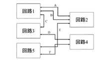
図11に示すように、従来の通信システムにおいて、回路1〜5は加算器および乗算器などの演算器や比較器などを有し、予め定められた手順に従って処理を行うものである。また、ここでは、A、B、C、D、EおよびFはそれぞれ、同期通信を行うために用いられる同期チャネルである。 As shown in FIG. 11, in a conventional communication system,
回路1は、同期チャネルAおよびBを介して回路2と接続されていると共に、同期チャネルCを介して回路3とも接続されている。また、回路3は同期チャネルDを介して回路4と接続されている。また、回路2は同期チャネルEを介して回路5と接続されている。さらに、回路5は同期チャネルFを介して回路4と接続されている。 The
図12は、図11に示す同期チャネルAを用いて回路1,2間でデータaの受け渡しを行う従来の同期チャネル通信システムの基本構成例を示すブロック図である。 FIG. 12 is a block diagram showing a basic configuration example of a conventional synchronization channel communication system that transfers data a between the
Send命令およびReceive命令は同期通信を表すために用いられる動作記述であり、Send(A,a)はReceive(A)に対して通信路(同期チャネル)Aを介して同期データaを送信することを示し、Receive(A)はSend(A,a)から通信路Aを介して同期データaを受信することを示している。 The Send command and the Receive command are operation descriptions used to represent synchronous communication, and Send (A, a) transmits synchronous data a to the Receive (A) via the communication channel (synchronous channel) A. Receive (A) indicates that the synchronization data a is received from the Send (A, a) via the communication path A.
図12に示す動作記述1は、回路1でSend(A,a)が実行されることを示しており、動作記述2は回路2でReceive(A)が実行されることを示している。同期チャネルA内のdataA信号は通信データ信号である。また、txA信号はSend命令が実行されたことを示す信号であり、HighのときにSend命令が実行されたことを示す。さらに、rxA信号はReceive命令が実行されたことを示す信号であり、HighのときReceive命令が実行されたことを示す。 An
図13は、図12に示す同期チャネル通信システムにおいて、同期データの送り出し側の回路が受け取り側の回路よりも先に準備ができて、Send命令がReceive命令よりも先に実行される場合の通信方法例を示すタイミング図である。 FIG. 13 shows communication in the synchronization channel communication system shown in FIG. 12 when the circuit on the synchronization data sending side is ready before the circuit on the receiving side, and the Send instruction is executed before the Receive instruction. FIG. 6 is a timing diagram illustrating an example method.
図13に示すように、回路1は、Send命令が実行されると、T11においてdataA信号にデータaを送出し、txA信号をHighにして、rxA信号がHighになるまで待機する。また、回路2は、Receive命令が実行されると、T13においてrxA信号をHighにする。 As shown in FIG. 13, when the Send instruction is executed, the
次に、回路1は、rxA信号がHighであることを確認すると、T14においてtxA信号をLowにする。また、回路2は、txA信号がHighであることを確認すると、dataA信号からデータaを受け取り、T14においてrxA信号をLowにする。 Next, when the
図14は、図12に示す同期チャネル通信システムにおいて、同期データの受け取り側の回路が送り出し側の回路よりも先に準備ができて、Receive命令がSend命令よりも先に実行された場合の通信方法例を示すタイミング図である。 FIG. 14 shows communication in the synchronous channel communication system shown in FIG. 12 when the circuit on the synchronization data receiving side is ready before the circuit on the sending side, and the Receive instruction is executed before the Send instruction. FIG. 6 is a timing diagram illustrating an example method.
図14に示すように、回路2は、Receive命令が実行されると、T21においてrxA信号をHighにして、txA信号がHighになるまで待機する。また、回路1は、Send命令が実行されると、T23においてdataA信号にデータaを送出し、txA信号をHighにする。 As shown in FIG. 14, when the Receive instruction is executed, the
次に、回路2は、txA信号がHighであることを確認すると、データ信号からデータaを受け取り、T24においてrxA信号をLowにする。また、回路1は、rxA信号がHighであることを確認すると、T24においてtxA信号をLowにする。 Next, when the
なお、図12に示すブロックにおいて、Send命令とReceive命令とが同時に実行された場合には、txA信号とrxA信号とが同時にHighになり、次のサイクルでtxA信号およびrxA信号の両方がLowになる。 In the block shown in FIG. 12, when the Send instruction and the Receive instruction are executed simultaneously, the txA signal and the rxA signal become High at the same time, and both the txA signal and the rxA signal become Low in the next cycle. Become.
次に、複数の回路間で同期通信によりデータ転送を行う他の方法として、通信を行う回路間にバスを設けるバス通信方法がある。 Next, as another method for transferring data between a plurality of circuits by synchronous communication, there is a bus communication method in which a bus is provided between the circuits performing communication.
このバスを用いたバス通信方法について、以下に、図15〜図21を用いて説明する。 A bus communication method using this bus will be described below with reference to FIGS.
図15は、バスを用いた従来のバス通信システムの構成を示すブロック図である。 FIG. 15 is a block diagram showing a configuration of a conventional bus communication system using a bus.
図15に示すように、この従来のバス通信システムにおいて、回路1〜5は加算器および乗算器などの演算器や比較器などを有し、予め定められた手順に従って処理を行うものである。また、バスインタフェース51a〜55aは、回路1〜5を共通バスに接続して共通バスを介して通信を行うためのものであり、バスプロトコルに従ってデータの書き込み/読み出し処理を制御する。ここで、共通バスに対して書き込み/読み出し要求を行うインタフェースをマスタインタフェース、共通バスからの書き込み/読み出し要求に対して応答するインタフェースをスレーブインタフェースとする。また、システム中で、マスタインタフェースを有する回路をマスタ回路、スレーブインタフェースを有する回路をスレーブ回路とする。 As shown in FIG. 15, in this conventional bus communication system,
このバス通信システムでは、一定期間、一つのマスタ回路がバスを占有し、スレーブ回路との間でデータ転送を行う。バス調停回路56は、一つのマスタ回路に対してバス転送を許可するものであり、同時に複数のマスタ回路がバスを使用しようとしている場合に、どのマスタ回路に占有権を与えるかを決定する。なお、システムの中でマスタ回路として動作する回路が一つしかない場合には、バス調停回路56は設けなくてもよい。 In this bus communication system, one master circuit occupies a bus for a certain period and performs data transfer with a slave circuit. The
また、ここでは、A、B、C、D、EおよびFはそれぞれ、同期通信を行うために用いられる同期ポートである。この同期ポートは、実際には、共通バスのアドレス空間に割り当てられたアドレスを意味する。同期ポートは、マスタ回路が通信先を指定するために用いるものであり、スレーブ回路側のバスインターフェイスに割り当てられている。 Here, A, B, C, D, E, and F are synchronization ports used for performing synchronous communication. This synchronous port actually means an address assigned to the address space of the common bus. The synchronization port is used by the master circuit to specify the communication destination, and is assigned to the bus interface on the slave circuit side.
図15に示す回路51はマスタ回路であり、回路52〜55はスレーブ回路である。スレーブ回路52はスレーブインターフェイス(バスインターフェイス)52aにアドレスAおよびBが割り当てられており、スレーブ回路53はスレーブインターフェイス53aにアドレスCおよびDが割り当てられている。また、スレーブ回路54はスレーブインターフェイス54aにアドレスFが割り当てられており、スレーブ回路55はスレーブインターフェイス55aにアドレスEが割り当てられている。 A
図16は、Send命令を実行する側の回路をマスタ回路とするような従来のバス通信システムの基本構成例を示すブロック図である。 FIG. 16 is a block diagram showing an example of the basic configuration of a conventional bus communication system in which the circuit on the side executing the Send instruction is a master circuit.
図16に示すように、動作記述1は回路1の動作を表す記述であり、回路1でSend(A,a)が実行されることを示している。また、動作記述2は回路2の動作を表す記述であり、回路2でReceive(A)が実行されることを示している。wdataA信号およびrdataA信号は通信データ信号である。また、wtxA信号およびrtxA信号はSend命令が実行されたことを示す信号であり、HighのときにSend命令が実行されたことを示す。さらに、wrxA信号およびrrxA信号はReceive命令が実行されたことを示す信号であり、HighのときReceive命令が実行されたことを示す。 As illustrated in FIG. 16, the
共通バス信号は、BUSaddr信号、BUSwdata信号、BUSwen信号およびBUSack信号によって構成される。BUSaddr信号はアドレスを指定するための信号であり、BUSwdata信号は書き込みデータ信号である。また、BUSwen信号は書き込み要求信号であり、Highのときに書き込み要求を出していることを示す。BUSack信号は通信終了信号であり、Highのときにバス転送が終了したことを示す。 The common bus signal includes a BUSaddr signal, a BUSwdata signal, a BUSwen signal, and a BUSack signal. The BUSaddr signal is a signal for designating an address, and the BUSwdata signal is a write data signal. The BUSwen signal is a write request signal and indicates that a write request is issued when High. The BUSack signal is a communication end signal, and indicates that the bus transfer has ended when High.
図16のバス通信システムでは、BUSwdata1信号およびBUSwdata2信号が共通バスのBUSwdata信号に接続され、BUSaddr1信号およびBUSaddr2信号が共通バスのBUSaddr信号に接続されている。また、BUSwen1信号およびBUSwen2信号が共通バスのBUSwen信号に接続され、BUSack1信号およびBUSack2信号が共通バスのBUSack信号に接続されている。 In the bus communication system of FIG. 16, the BUSwdata1 signal and the BUSwdata2 signal are connected to the BUSwdata signal of the common bus, and the BUSaddr1 signal and the BUSaddr2 signal are connected to the BUSaddr signal of the common bus. In addition, the BUSwen1 signal and the BUSwen2 signal are connected to the BUSwen signal of the common bus, and the BUSack1 signal and the BUSack2 signal are connected to the BUSack signal of the common bus.
以下に、回路1とマスタインタフェース1との間の通信に図13の方法を用い、回路2とスレーブインタフェース2との間の通信に図14の方法を用いた場合について、インタフェース部の動作を説明する。 The operation of the interface unit will be described below in the case where the method of FIG. 13 is used for communication between the
wdataA信号およびrdataA信号は、図13および図14のdataAに対応し、wtxA信号およびrtxA信号は図13および図14のtxA信号に対応し、wrxA信号およびrrxA信号は図13および図14のrxA信号に対応する。 The wdataA signal and the rdataA signal correspond to the dataA in FIGS. 13 and 14, the wtxA signal and the rtxA signal correspond to the txA signal in FIGS. 13 and 14, and the wrxA signal and the rrxA signal correspond to the rxA signal in FIGS. Corresponding to
図17は、図16に示すバス通信システムにおいて、同期データの送り出し側の回路が受け取り側の回路よりも先に準備ができて、Send命令がReceive命令よりも先に実行された場合のバス通信方法例を示すタイミング図である。なお、リセット後、BUSwen信号、BUSack信号、wtxA信号、wrxA信号、rtxA信号およびrrxA信号の初期値はLowレベルとする。 FIG. 17 is a diagram showing a bus communication in the case where the synchronous data sending circuit is ready before the receiving circuit and the Send instruction is executed before the Receive instruction in the bus communication system shown in FIG. FIG. 6 is a timing diagram illustrating an example method. Note that after resetting, the initial values of the BUSwen signal, BUSack signal, wtxA signal, wrxA signal, rtxA signal, and rrxA signal are set to the Low level.
図17に示すように、まず、T31において、回路1がwtxA信号(Send命令実行信号)をHighにすると、マスタインタフェース1は、どの同期ポートへの要求かを判断する。T32において、マスタインターフェイス1は、共通バスに対してBUSaddr信号にアドレスA、BUSwdata信号にデータaを送出し、BUSwen信号(書き込み要求信号)をHighにして、BUSack信号(通信終了信号)がHighになるまで待機する。 As shown in FIG. 17, first, at T31, when the
次に、T33において、回路2がrrxA信号(Receive命令実行信号)をHighにすると、スレーブインタフェース2は、BUSaddr信号がアドレスAで、かつ、BUSwen信号がHigh(アドレスAへの書き込み要求)であることを確認する。T34において、スレーブインターフェイス2は、BUSack信号(通信終了信号)を1サイクルの間Highにし、さらに、rdataA信号にBUSwdata信号のデータaを送出し、rtxA信号(Send命令実行信号)を1サイクルの間Highにする。 Next, at T33, when the
マスタインタフェース1は、BUSack信号がHighになると、T34においてwrxA信号(Receive命令実行信号)を1サイクルの間Highにする。T35で同期通信が完了する。 When the BUSack signal becomes High, the
図18は、図16に示すバス通信システムにおいて、同期データの受け取り側の回路が送り出し側の回路よりも先に準備ができて、Receive命令がSend命令よりも先に実行された場合のバス通信方法例を示すタイミング図である。なお、リセット後、BUSwen信号、BUSack信号、wtxA信号、wrxA信号、rtxA信号およびrrxA信号の初期値はLowレベルとする。 FIG. 18 shows a bus communication in the case where the synchronous data receiving circuit is ready before the sending circuit in the bus communication system shown in FIG. 16 and the Receive instruction is executed before the Send instruction. FIG. 6 is a timing diagram illustrating an example method. Note that after resetting, the initial values of the BUSwen signal, BUSack signal, wtxA signal, wrxA signal, rtxA signal, and rrxA signal are set to the Low level.
図18に示すように、まず、T41において、回路2がrrxA(Receive命令実行信号)をHighにすると、スレーブインタフェース2は、アドレスAへの書き込み要求があるまで待機する。 As shown in FIG. 18, first, at T41, when the
次に、T42において、回路1がwtxA信号(Send命令実行信号)をHighにすると、マスタインタフェース1は、どの同期ポートへの要求かを判断する。T43において、マスタインターフェイス1は、共通バスに対してBUSaddr信号にアドレスA、BUSwdata信号にデータaを送出し、BUSwen信号(書き込み要求信号)をHighにして、BUSack信号(通信終了信号)がHighになるまで待機する。 Next, in T42, when the
さらに、T44において、スレーブインタフェース2は、BUSaddr信号がアドレスAで、かつ、BUSwen信号がHigh(アドレスAへの書き込み要求)であることを確認して、BUSack信号(通信終了信号)を1サイクルの間Highにし、さらに、rdataA信号にBUSwdata信号のデータaを送出し、rtxA信号(Send命令実行信号)を1サイクルの間Highにする。マスタインタフェース1は、BUSack信号(通信終了信号)がHighになると、T44においてwrxA信号(Receive命令実行信号)を1サイクルの間Highにする。T45で同期通信が完了する。 Further, at T44, the
上記図17および図18に示す同期通信例において、マスタ回路がすぐにバスの占有権が得られない場合でも、バスの占有権が得られるまで、wrx信号をLowにしておけば、同様に同期通信が可能である。 In the synchronous communication examples shown in FIG. 17 and FIG. 18, even if the master circuit cannot immediately obtain the right to occupy the bus, if the wrx signal is kept low until the right to occupy the bus is obtained, the synchronization is similarly performed. Communication is possible.
図19は、Receive命令を実行する側の回路をマスタ回路とするような従来のバス通信システムの基本構成例を示すブロック図である。 FIG. 19 is a block diagram showing an example of a basic configuration of a conventional bus communication system in which a circuit on the side executing a Receive instruction is a master circuit.
図19に示すように、動作記述1は回路1の動作を表す記述であり、回路1でReceive(A)が実行されることを示している。また、動作記述2は回路2の動作を表す記述であり、回路2でSend(A,a)が実行されることを示している。wdataA信号およびrdataA信号は通信データ信号である。また、wtxA信号およびrtxAはSend命令が実行されたことを示す信号であり、HighのときにSend命令が実行されたことを示す。さらに、wrxA信号およびrrxA信号はReceive命令が実行されたことを示す信号であり、HighのときReceive命令が実行されたことを示す。 As illustrated in FIG. 19, the
共通バス信号は、BUSaddr信号、BUSrdata信号、BUSren信号およびBUSack信号によって構成される。BUSaddr信号はアドレスを指定するための信号であり、BUSrdata信号は読み出しデータ信号である。また、BUSren信号は読み出し要求信号であり、Highのときに読み出し要求を出していることを示す。BUSack信号は通信終了信号であり、Highのときにバス転送が終了したことを示す。 The common bus signal includes a BUSaddr signal, a BUSrdata signal, a BUSren signal, and a BUSack signal. The BUSaddr signal is a signal for designating an address, and the BUSrdata signal is a read data signal. The BUSren signal is a read request signal and indicates that a read request is issued when the signal is High. The BUSack signal is a communication end signal, and indicates that the bus transfer has ended when High.
図19のバス通信システムでは、BUSrdata1信号およびBUSrdata2信号が共通バスのBUSrdata信号に接続され、BUSaddr1信号およびBUSaddr2信号が共通バスのBUSaddr信号に接続されている。また、BUSren1信号およびBUSren2信号が共通バスのBUSren信号に接続され、BUSack1信号およびBUSack2信号が共通バスのBUSack信号に接続されている。 In the bus communication system of FIG. 19, the BUSrdata1 signal and the BUSrdata2 signal are connected to the BUSrdata signal of the common bus, and the BUSaddr1 signal and the BUSaddr2 signal are connected to the BUSaddr signal of the common bus. The BUSren1 signal and the BUSren2 signal are connected to the BUSren signal of the common bus, and the BUSack1 signal and the BUSack2 signal are connected to the BUSack signal of the common bus.
以下に、回路1とマスタインタフェース1との間の通信に図13の方法を用い、回路2とスレーブインタフェース2との間の通信に図14の方法を用いた場合について、インタフェース部の動作を説明する。 The operation of the interface unit will be described below in the case where the method of FIG. 13 is used for communication between the
wdataA信号およびrdataA信号は、図13および図14のdataAに対応し、wtxA信号およびrtxA信号は図13および図14のtxA信号に対応し、wrxA信号およびrrxA信号は図13および図14のrxA信号に対応している。 The wdataA signal and the rdataA signal correspond to the dataA in FIGS. 13 and 14, the wtxA signal and the rtxA signal correspond to the txA signal in FIGS. 13 and 14, and the wrxA signal and the rrxA signal correspond to the rxA signal in FIGS. It corresponds to.
図20は、図19に示すバス通信システムにおいて、同期データの送り出し側の回路が受け取り側の回路よりも先に準備ができて、Send命令がReceive命令よりも先に実行された場合の通信方法例を示すタイミング図である。なお、リセット後、BUSren信号、BUSack信号、wtxA信号、wrxA信号、rtxA信号およびrrxA信号の初期値はLowレベルとする。 FIG. 20 shows a communication method in the case where the synchronous data sending circuit is ready before the receiving circuit and the Send command is executed before the Receive command in the bus communication system shown in FIG. It is a timing diagram which shows an example. Note that after resetting, the initial values of the BUSren signal, BUSack signal, wtxA signal, wrxA signal, rtxA signal, and rrxA signal are set to the Low level.
図20に示すように、まず、T51において、回路2がwtxA信号(Send命令実行信号)をHighにすると、スレーブインタフェース2は、アドレスAへの読み出し要求があるまで待機する。 As shown in FIG. 20, first, at T51, when the
次に、T52において、回路1がrrxA信号(Receive命令実行信号)をHighにすると、マスタインタフェース1は、どの同期ポートへの要求かを判断する。T53において、マスタインターフェイス1は、共通バスに対してBUSaddr信号にアドレスAを送出し、BUSren信号(読み出し要求信号)をHighにして、BUSack信号(通信終了信号)がHighになるまで待機する。 Next, at T52, when the
さらに、T54において、スレーブインタフェース2は、BUSaddr信号がアドレスAで、かつ、BUSren信号がHigh(アドレスAへの読み出し要求)であることを確認して、共通バスに対してBUSrdata信号にデータaを送出し、BUSack信号(通信終了信号)を1サイクルの間Highにし、さらにwrxA信号(Receive命令実行信号)を1サイクルの間Highにする。 Further, at T54, the
マスタインタフェース1は、BUSack信号がHighになると、T54においてrdataA信号にBUSrdata信号のデータaを送出し、rtxA信号(Send命令実行信号)を1サイクルの間だけHighにする。T55で同期通信が完了する。 When the BUSack signal becomes High, the
図21は、図19に示すバス通信システムにおいて、同期データの受け取り側の回路が送り出し側の回路よりも先に準備ができて、Receive命令がSend命令よりも先に実行された場合の通信方法例を示すタイミング図である。なお、リセット後、BUSwen信号、BUSack信号、wtxA信号、wrxA信号、rtxA信号およびrrxA信号の初期値はLowとする。 FIG. 21 shows a communication method in the case where the synchronous data receiving circuit is ready before the sending circuit and the Receive instruction is executed before the Send instruction in the bus communication system shown in FIG. It is a timing diagram which shows an example. Note that after resetting, the initial values of the BUSwen signal, BUSack signal, wtxA signal, wrxA signal, rtxA signal, and rrxA signal are set to Low.
図21に示すように、まず、T61において、回路1がrrxA信号(Receive命令実行信号)をHighにすると、マスタインタフェース1は、どの同期ポートへの要求かを判断する。 As shown in FIG. 21, first, at T61, when the
次に、T62において、マスタインターフェイス1は、共通バスに対してBUSaddr信号にアドレスAを送出し、BUSren信号(読み出し要求信号)をHighにして、BUSack信号(通信終了信号)がHighになるまで待機する。 Next, at T62, the
さらに、T63において、回路2がwtxA信号(Send命令実行信号)をHighにすると、スレーブインタフェース2は、BUSaddr信号がアドレスAで、かつ、BUSren信号がHigh(アドレスAへの読み出し要求)であることを確認する。T64において、スレーブインターフェイス2は、BUSack信号(通信終了信号)を1サイクルの間Highにし、さらに、共通バスに対してBUSrdata信号にデータaを送出し、wrxA信号(Receive命令実行信号)を1サイクルの間だけHighにする。 In T63, when the
マスタインタフェース1は、BUSack信号(通信終了信号)がHighになると、T64においてrdataA信号にBUSrdata信号のデータaを送出し、rtxA信号(Send命令実行信号)を1サイクルの間Highにする。T65で同期通信が完了する。 When the BUSack signal (communication end signal) becomes High, the
上記図20および図21に示す同期通信例において、マスタ回路がすぐにバスの占有権が得られない場合でも、バスの占有権が得られるまで、rtx信号をLowにしておけば、同様に同期通信が可能である。 In the synchronous communication examples shown in FIG. 20 and FIG. 21, even if the master circuit cannot obtain the right to occupy the bus immediately, if the rtx signal is kept low until the right to occupy the bus is obtained, the synchronization is similarly performed. Communication is possible.
なお、上記説明では、一つの回路がマスタインターフェイスまたはスレーブインタフェースの一方を有する例について示したが、マスタインタフェースおよびスレーブインタフェースの両方を有する構成も可能である。
しかしながら、上述した従来の同期チャネル通信方法では、同期チャネルの数に比例して回路間の配線が増えていく。このため、同期チャネルが多数用いられる場合には、回路間の配線が非常に多くなり、チップ面積が極端に大きくなったり、レイアウトができなくなったりするおそれがある。 However, in the conventional synchronization channel communication method described above, the wiring between circuits increases in proportion to the number of synchronization channels. For this reason, when a large number of synchronization channels are used, the wiring between circuits becomes very large, and there is a possibility that the chip area becomes extremely large or the layout cannot be performed.
また、上述した従来のバス通信方法では、同期ポートが多数用いられても、上記従来の同期チャネル通信方法のように配線が増えることはないが、複数の回路が共通バスに接続されている場合には、以下のようなデッドロックが発生するおそれがある。 In the conventional bus communication method described above, even if a large number of synchronization ports are used, the number of wirings does not increase as in the conventional synchronization channel communication method, but a plurality of circuits are connected to a common bus. May cause the following deadlock.
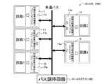
例えば図22に示すように、Receive命令を実行する回路をマスタ回路とする従来のバス通信システムにおいて、回路1ではReceive(A)が実行され、回路3ではReceive(B)が実行され、回路2ではSend(A,a)が実行された後、Send(B,b)が実行されるようなバス通信システムの構成について考える。 For example, as shown in FIG. 22, in a conventional bus communication system in which a circuit that executes a Receive instruction is a master circuit, Receive (A) is executed in
図22に示すバス通信システムにおいて、回路1よりも先に回路3のReceive命令が実行され、マスタインタフェース3に共通バスの占有権が与えられて、同期ポートBに対してデータの読み出し要求が行われた場合でも、データ読み出し先の回路2では、同期ポートAによる同期通信が確立していないと、同期ポートBによる同期通信は実行されず、応答信号を返すことができない。 In the bus communication system shown in FIG. 22, the Receive instruction of the
このとき、スレーブインタフェース2では、同期ポートAに対する読み出し要求を待っている状態であるが、マスタインタフェース1から同期ポートAに対する読み出し要求が出されていても、マスタインタフェース3によって共通バスが占有されているため、バス調停回路56は、マスタインタフェース1に共通バスの占有権を与えることができない。このため、スレーブインタフェース2では、永久に同期ポートAに対する読み出し要求を待っている状態が続き、共通バスが占有されたまま、デッドロックが起こってしまう。 At this time, the
ここで、一定のサイクル以上、あるマスタ回路(マスタインターフェイス)によって共通バスが占有されると、共通バスとの接続を一旦切断し、他のマスタ回路にバスの占有権を与えるような機構が組み込まれているバス調停回路を用いることによって、デッドロックが生じないようにすることが考えられるが、この場合でも、共通バスとの接続を切断するまでの間のサイクルは無駄になってしまう。 Here, when a common bus is occupied by a certain master circuit (master interface) for a certain cycle or longer, a mechanism is built in that disconnects the connection to the common bus and gives the bus ownership to other master circuits. Although it is conceivable to prevent the occurrence of deadlock by using the bus arbitration circuit, the cycle until disconnection from the common bus is wasted even in this case.
本発明は、上記従来の問題を解決するもので、回路間の配線を少なくし、かつデッドロックを防いで効率よく同期通信を行うことができるバス通信システムを提供することを目的とする。 SUMMARY OF THE INVENTION The present invention solves the above-described conventional problems, and an object of the present invention is to provide a bus communication system that can efficiently perform synchronous communication while reducing wiring between circuits and preventing deadlock.
本発明のバス通信システムは、マスタ回路とスレーブ回路間でバスを介して同期通信によるデータ転送を可能とするバス通信システムにおいて、複数のマスタ回路から転送要求が出されている場合、連続して同じアドレスに転送要求を出すマスタ回路に対して、連続して予め定められた回数以上、バスの占有権を与えないように調停するバス調停回路が設けられ、該スレーブ回路は、該マスタ回路から転送要求を受けた場合、該マスタ回路にバス転送終了を通知すると共にデータ転送準備ができているかどうかを通知し、該マスタ回路は、該データ転送準備ができているとの通知を受けた場合、データ転送処理を終了し、該データ転送準備ができていないとの通知を受けた場合、該スレーブ回路への転送要求を再度実行し、該スレーブ回路は、該マスタ回路から転送要求を受け、かつ該マスタ回路にデータ転送準備ができていないとの通知をした場合、予め定められたサイクル数だけ待った後、未だデータ転送準備ができていない場合、該マスタ回路にバス転送終了を通知すると共にデータ転送準備ができていないとの通知をし、待っている途中でデータ転送準備ができた場合には、直ちに該マスタ回路にバス転送終了を通知すると共にデータ転送準備ができているとの通知をするものであり、そのことにより上記目的が達成される。
The bus communication system of the present invention is a bus communication system that enables data transfer by synchronous communication between a master circuit and a slave circuit via a bus. When transfer requests are issued from a plurality of master circuits, the bus communication system continuously A bus arbitration circuit is provided for arbitrating a master circuit that issues a transfer request to the same address so as not to give the right to occupy a bus continuously for a predetermined number of times. When a transfer request is received, the master circuit is notified of the end of bus transfer and whether data transfer is ready, and the master circuit is notified that the data transfer is ready , it ends the data transfer process, when receiving the notification that no can the data transfer preparation,performs the transfer request to the slave circuitagain, the slave circuit When receiving a transfer request from the master circuit and notifying the master circuit that the data transfer is not ready, after waiting for a predetermined number of cycles, if the data transfer is not ready yet, the master circuit Notifying the circuit of the end of bus transfer and notifying that the data transfer is not ready. If the data transfer is ready while waiting, it immediately notifies the master circuit of the end of the bus transfer and data. The notification is made that the transfer is ready, and the above object is achieved.
また、好ましくは、本発明のバス通信システムおいて、前記待っている途中でデータ転送準備ができた場合に、前記マスタ回路にバス転送終了を通知する前に、データを受け取るかまたはデータを送信する。Also, preferably,be had your bus communication system of the presentinvention, the transmission if the data can be transferred ready while you are waiting above, before notifying the termination bus transfer to the master circuit, or receives the data or the data To do .
さらに、好ましくは、本発明のバス通信システムおけるマスタ回路側から、前記スレーブ回路にデータ書き込み処理を実行させる場合、該マスタ回路から書き込みデータを送り出し、該スレーブ回路で書き込みデータを受け取るデータ転送処理において、
前記スレーブ回路は、該マスタ回路から前記転送要求としてデータ書き込み要求があった場合、該マスタ回路にバス転送終了を通知すると共にデータ書き込み準備ができているかどうかを通知し、
該マスタ回路は、該スレーブ回路から、データ書き込み準備ができているとの通知を受けた場合、該データ書き込み処理を終了し、該スレーブ回路からデータ書き込み準備ができていないとの通知を受けた場合、該スレーブ回路にデータ書き込み要求を再度出す。Further preferably, in the data transfer process in which the master circuit side in the bus communication system of the present invention causes the slave circuit to execute data write processing, the write data is sent from the master circuit and the write data is received by the slave circuit. ,
When there is a data write request from the master circuit as the transfer request, the slave circuit notifies the master circuit of the completion of the bus transfer and notifies whether the data write is ready,
When the master circuit receives a notification from the slave circuit that the data writing is ready, the master circuit finishes the data writing process and receives a notification from the slave circuit that the data writing preparation is not ready. In this case, a data write request is issued again to the slave circuit.
さらに、好ましくは、本発明のバス通信システムおけるマスタ回路側から、前記スレーブ回路からのデータ読み出し処理を実行させる場合、該スレーブ回路から読み出しデータを送り出し、該マスタ回路で読み出しデータを受け取るデータ転送処理において、前記スレーブ回路は、該マスタ回路から前記転送要求としてデータ読み出し要求があった場合、該マスタ回路にバス転送終了を通知すると共にデータ読み出し準備ができているかどうかを通知し、
該マスタ回路は、該スレーブ回路からデータ読み出し準備ができているとの通知を受けた場合、該データ読み出し処理を終了し、該スレーブ回路からデータ読み出し準備ができていないとの通知を受けた場合、該スレーブ回路にデータ読み出し要求を再度出す。Further preferably, in the case where data reading processing from the slave circuit is executed from the master circuit side in the bus communication system of the present invention, data transfer processing for sending read data from the slave circuit and receiving read data by the master circuit When the slave circuit receives a data read request as the transfer request, the slave circuit notifies the master circuit of the completion of the bus transfer and notifies whether the data read is ready.
When the master circuit receives a notification from the slave circuit that data readiness is ready, the master circuit terminates the data read processing and receives a notification from the slave circuit that data readiness is not ready The data read request is issued again to the slave circuit.
さらに、好ましくは、本発明のバス通信システムおけるバス調停回路は、複数のマスタ回路から転送要求が出されているときに、該複数のマスタ回路に優先順位を割り当て、優先順位が高いマスタ回路から順にバスの占有権を与え、優先順位が高いマスタ回路に対して同じアドレスに予め定められた回数、連続してバスの占有権を与えた場合に、その連続してバスの占有権が与えられたマスタ回路の優先順位を一旦下げて、他のマスタ回路にバスの占有権を与えるように調停する。 Further preferably, the bus arbitration circuit in the bus communication system of the present invention assigns a priority to the plurality of master circuits when a transfer request is issued from the plurality of master circuits, and starts from a master circuit having a high priority. When the right to occupy the bus is given in sequence and the right to occupy the bus continuously for a predetermined number of times for the master circuit with the highest priority, the right to occupy the bus is continuously given. The priority order of the master circuit is once lowered, and arbitration is performed so as to give the bus mastership to other master circuits.
さらに、好ましくは、本発明のバス通信システムおけるバス調停回路は、複数のマスタ回路から転送要求が出されているときに、該複数のマスタ回路に優先順位を割り当て、優先順位が高いマスタ回路から順にバスの占有権を与え、優先順位が高いマスタ回路に対して同じアドレスに予め定められた回数、連続してバスの占有権を与えた場合に、優先順位に関係なく、ランダムにマスタ回路にバスの占有権を与えるように調停する。 Further preferably, the bus arbitration circuit in the bus communication system of the present invention assigns a priority to the plurality of master circuits when a transfer request is issued from the plurality of master circuits, and starts from a master circuit having a high priority. When the bus ownership is given to the master circuit in a predetermined number of times at the same address for the master circuit with the highest priority, the master circuit is randomly assigned to the master circuit regardless of the priority. Arbitrate to give bus ownership.
さらに、好ましくは、本発明のバス通信システムおけるマスタ回路は、バスに対して複数のデータ転送要求を同時にする場合に、予め定められた回数以上、連続して同じデータ転送要求が続かないように調停する内部調停回路を有している。 Further, preferably, the master circuit in the bus communication system of the present invention prevents the same data transfer request from continuing continuously for a predetermined number of times when a plurality of data transfer requests are simultaneously made to the bus. It has an internal arbitration circuit that arbitrates.
さらに、好ましくは、本発明のバス通信システムおける内部調停回路は、複数のデータ転送要求があるときに、該複数のデータ転送要求に優先順位を割り当て、該優先順位が高いデータ転送要求から順にデータ転送要求を実行させ、優先順位が高いデータ転送要求に対して予め定められた回数、連続して同じデータ転送要求を実行した場合に、そのデータ転送要求の優先順位を一旦下げて、他のデータ転送要求を実行させるように調停する。 Further preferably, the internal arbitration circuit in the bus communication system of the present invention assigns a priority to the plurality of data transfer requests when there are a plurality of data transfer requests, and performs data transfer in order from the data transfer request having the highest priority. When a transfer request is executed and the same data transfer request is executed continuously for a predetermined number of times for a data transfer request with a high priority, the priority of the data transfer request is lowered once and other data Arbitrate to execute the transfer request.
さらに、好ましくは、本発明のバス通信システムおける内部調停回路は、複数のデータ転送要求があるときに、該複数のデータ転送要求に優先順位を割り当て、該優先順位が高いデータ転送要求から順にデータ転送要求を実行し、優先順位が高いデータ転送要求に対して予め定められた回数、連続して同じデータ転送要求を実行した場合に、優先順位に関係なく、ランダムに他のデータ転送要求を実行させるように調停する。 Further preferably, the internal arbitration circuit in the bus communication system of the present invention assigns a priority to the plurality of data transfer requests when there are a plurality of data transfer requests, and performs data transfer in order from the data transfer request having the highest priority. When a transfer request is executed and the same data transfer request is executed continuously for a predetermined number of times for a data transfer request with a high priority, another data transfer request is executed at random regardless of the priority. Mediate so that
上記構成により、以下に、本発明の作用について説明する。 The operation of the present invention will be described below with the above configuration.
本発明にあっては、マスタ回路とスレーブ回路との間でバスを介して同期通信によりデータ転送を行うバス通信システム(バス通信装置)において、複数のマスタ回路から転送要求が出されているときに、スレーブ回路によって、バス通信(バス転送)が終了したか否かの通知(バス転送終了通知)すると共に、スレーブ回路側でデータ転送準備ができているかどうかを通知する。マスタ回路は、データ転送準備が完了している場合(データ転送準備ができている場合)にはデータ転送を終了し、データ転送準備が完了していない場合(データ転送準備ができていない場合)にはデータ転送要求出力を再度行う。 In the present invention, when a transfer request is issued from a plurality of master circuits in a bus communication system (bus communication device) that performs data transfer by synchronous communication between a master circuit and a slave circuit via a bus. In addition, the slave circuit notifies whether or not the bus communication (bus transfer) has ended (bus transfer end notification) and notifies whether the slave circuit side is ready for data transfer. The master circuit terminates data transfer when data transfer preparation is complete (when data transfer preparation is complete), and data transfer preparation is not complete (when data transfer preparation is not complete) In this case, the data transfer request is output again.
マスタ回路から転送要求を受けたときにスレーブ回路のデータ転送準備ができていない場合には、共通バスが一旦開放される。このとき、バス調停回路は、同じアドレスに対して転送要求を出しているマスタ回路に連続して予め定められた回数(n=0以上の整数)以上、占有権を与えず、他のマスタ回路にバス占有権を与えることができる。このため、従来のようなデッドロックを生じることなく、バスをより有効に利用することができる。 If the slave circuit is not ready for data transfer when a transfer request is received from the master circuit, the common bus is temporarily released. At this time, the bus arbitration circuit does not give the occupation right more than a predetermined number of times (an integer greater than or equal to n = 0) continuously to the master circuit that has issued a transfer request to the same address, and other master circuits Can be given bus ownership. For this reason, the bus can be used more effectively without causing the conventional deadlock.
バス調停回路は、例えば、複数のマスタ回路に優先順位を割り当て、優先順位が高い転送要求を有するマスタ回路から順にバスの占有権を与える。複数のマスタ回路から転送要求が出ている場合に、優先順位が高いマスタ回路からから同じアドレスに対して連続して予め定められた回数(m=1以上の整数)以上、占有権を与えると、そのマスタ回路の優先順位を一旦下げるか、または、乱数によってランダムに別のマスタ回路を選択し、他のマスタ回路に占有権を与えるようにする。 For example, the bus arbitration circuit assigns priorities to a plurality of master circuits, and gives the right to occupy the buses in order from the master circuit having a transfer request with a higher priority. When transfer requests are issued from a plurality of master circuits, if an occupation right is given for a predetermined number of times (an integer greater than or equal to 1) continuously from the master circuit having a higher priority to the same address. Then, the priority of the master circuit is lowered once, or another master circuit is selected at random by a random number, and an occupation right is given to the other master circuit.
また、一つのマスタ回路からバスに対して複数のデータ転送要求が同時に発生する場合には、予め定められた回数(m=1以上の整数)以上、連続して同じデータ転送が続かないように、マスタ回路内部で調停する内部調停回路がマスタ回路毎に設けられている。 Further, when a plurality of data transfer requests are simultaneously generated from one master circuit to the bus, the same data transfer is not continued continuously for a predetermined number of times (an integer equal to or greater than 1). An internal arbitration circuit that arbitrates within the master circuit is provided for each master circuit.
この内部調停回路では、データ転送要求に優先順位を割り当て、優先順位が高いデータ転送要求から順にデータ転送要求を実行する。複数のデータ転送要求がある場合に、優先順位が高いデータ転送に予め定められた回数、連続して同じデータ転送要求を実行すると、そのデータ転送要求の優先順位を一旦下げるか、または、乱数によってランダムに別のデータ転送要求を選択し、他のデータ転送要求を実行するようにする。 In this internal arbitration circuit, a priority is assigned to the data transfer request, and the data transfer request is executed in order from the data transfer request having the highest priority. When there are a plurality of data transfer requests, if the same data transfer request is executed consecutively for a predetermined number of times for data transfer with a high priority, the priority of the data transfer request is lowered once or by a random number A different data transfer request is selected at random, and another data transfer request is executed.
本発明のバス通信装置においては、例えば、データを送り出す方がマスタ回路となり、データを受け取る方がスレーブ回路となって、マスタ回路がスレーブ回路に対して書き込み処理を行うことにより、同期通信によるデータ転送を行う。マスタ回路から同期通信データの書き込み要求が出されたとき、指定されたスレーブ回路は、同期通信データの受け取り準備ができている場合には、データを受け取って、直ちにバス通信を終了させるため、通信終了信号によりバス転送の終了を通知する。また、受け取り準備ができていない場合には、nサイクルの間、待ってから通信を終了させるようにしてもよい。nサイクルの途中で受け取り準備ができた場合には、データを受け取って、直ちにバス通信を終了させる。nが0の場合には、待たずに、直ちにバス通信を終了させる。 In the bus communication device of the present invention, for example, the one that sends data becomes a master circuit, the one that receives data becomes a slave circuit, and the master circuit performs a write process on the slave circuit, so that data by synchronous communication is obtained. Perform the transfer. When a request for writing synchronous communication data is issued from the master circuit, the designated slave circuit receives data and immediately terminates bus communication if it is ready to receive synchronous communication data. The end of the bus transfer is notified by the end signal. If it is not ready to receive, the communication may be terminated after waiting for n cycles. If it is ready to receive in the middle of n cycles, the data is received and the bus communication is immediately terminated. If n is 0, the bus communication is immediately terminated without waiting.
バス転送の終了を通知するときに、スレーブ回路は、マスタ回路に対して同期通信データを受け取ったか否かの情報を転送完了信号によって通知する。受け取り準備ができている場合には、データを受け取って、受け取りが完了したことを通知し、受け取り準備ができていない場合には、受け取り準備ができていないことを通知する。 When notifying the end of the bus transfer, the slave circuit notifies the master circuit of information indicating whether or not the synchronous communication data has been received by a transfer completion signal. If the data is ready to be received, the data is received to notify that the data has been received. If the data is not ready to be received, the data is notified that the data is not ready to be received.
マスタ回路は、バス転送の終了通知を受けると、転送完了信号から、再度データ転送を行うか否かを判断する。データ転送要求が完了していれば、この時点で同期通信処理を終了する。データ転送要求が完了していなければ、同期通信のデータ転送要求を繰り返し行う。 When the master circuit receives the completion notification of the bus transfer, it determines from the transfer completion signal whether or not to transfer the data again. If the data transfer request has been completed, the synchronous communication process is terminated at this point. If the data transfer request is not completed, the synchronous communication data transfer request is repeatedly performed.
このとき、バス調停回路は、他のマスタ回路がデータ転送要求を出していれば、他のマスタ回路にバスの占有権を与えることにより、バスを有効に利用できてデッドロックが生じることがなくなる。 At this time, if another master circuit has issued a data transfer request, the bus arbitration circuit can effectively use the bus without causing a deadlock by giving the other master circuit the right to occupy the bus. .
次に、データを受け取る方がマスタ回路となり、データを送り出す方がスレーブ回路となって、マスタ回路がスレーブ回路に対して読み出し処理を行うことにより、同期通信によりデータ転送処理を行うことができる。 Next, the one that receives data becomes the master circuit, the one that sends out data becomes the slave circuit, and the master circuit performs read processing on the slave circuit, whereby data transfer processing can be performed by synchronous communication.
この場合、マスタ回路から同期通信データの読み出し要求が出されたとき、指定されたスレーブ回路は、同期通信データの送信準備ができている場合には、データを送信して、直ちにバス通信を終了させるため、通信終了信号によりバス転送の終了を通知する。送信準備ができていない場合には、nサイクルの間、待ってから通信を終了させる。nサイクルの途中に送信準備ができた場合には、データを送信して、直ちにバス通信を終了させる。nが0の場合には、待たずに、直ちにバス通信を終了させる。 In this case, when a read request for synchronous communication data is issued from the master circuit, the designated slave circuit transmits data and immediately terminates bus communication if it is ready to transmit synchronous communication data. Therefore, the end of bus transfer is notified by a communication end signal. If transmission is not ready, communication is terminated after waiting for n cycles. If the transmission is ready in the middle of n cycles, data is transmitted and the bus communication is immediately terminated. If n is 0, the bus communication is immediately terminated without waiting.
バス転送の終了を通知するときに、スレーブ回路は、マスタ回路に対して同期通信データを送信したか否かの情報を転送完了信号によって通知する。送信準備ができている場合には、データを送信して、送信が完了したことを通知し、送信準備ができていない場合には、送信準備ができていないことを通知する。 When notifying the end of the bus transfer, the slave circuit notifies the master circuit whether or not the synchronous communication data has been transmitted by a transfer completion signal. When the transmission is ready, the data is transmitted to notify that the transmission is completed. When the transmission is not ready, the data is notified that the transmission is not ready.
マスタ回路は、バス転送の終了通知を受けると、転送完了信号から、データ転送を再度行うか否かを判断する。データ転送が完了していれば、この時点で同期通信処理を終了する。データ転送が完了していなければ、同期通信のデータ転送要求を繰り返し行う。 When the master circuit receives the notification of the completion of the bus transfer, it determines from the transfer completion signal whether or not to perform the data transfer again. If the data transfer has been completed, the synchronous communication process is terminated at this point. If the data transfer is not completed, the data transfer request for synchronous communication is repeatedly performed.
このとき、バス調停回路は、他のマスタ回路がデータ転送要求を出していれば、他のマスタ回路にバスの占有権を与えることにより、バスを有効に利用できてデッドロックが生じることがなくなる。 At this time, if another master circuit has issued a data transfer request, the bus arbitration circuit can effectively use the bus without causing a deadlock by giving the other master circuit the right to occupy the bus. .
以上により、本発明によれば、同期通信を行う回路間に共通バスを設けて回路間の配線を少なくすることができる。また、データ転送の準備状態や転送完了を通知して必要なときのみ共通バスを占有し、共通バスを占有し続けることがないため、効率よく同期通信を行うバス通信システムを実現することができる。 As described above, according to the present invention, it is possible to reduce the wiring between circuits by providing a common bus between circuits performing synchronous communication. In addition, a bus communication system that efficiently performs synchronous communication can be realized because the common bus is occupied only when necessary by notifying the data transfer preparation state and transfer completion, and does not continue to occupy the common bus. .
以下に、本発明のバス通信システムの実施形態について、図面を参照しながら説明する。 Embodiments of a bus communication system according to the present invention will be described below with reference to the drawings.
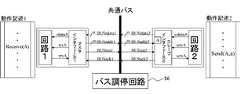
図1は、本発明の一実施形態であるバス通信システムの要部構成を示すブロック図である。 FIG. 1 is a block diagram showing a main configuration of a bus communication system according to an embodiment of the present invention.
図1に示すように、本実施形態のバス通信システム20において、複数の回路11〜15が共有バスを介して接続されており、共有バスにはバス調停回路16が接続されている。 As shown in FIG. 1, in the
複数の回路11〜15にはそれぞれ回路1〜5がそれぞれ設けられている。回路1〜5はそれぞれ、加算器および乗算器などの演算器や比較器などからなり、予め定められた手順に従って処理を行うものである。また、複数の回路11〜15にはそれぞれバスインタフェース11a〜15aがそれぞれ設けられている。バスインタフェース11a〜15aは、回路1〜5を共通バスに接続して共通バスを介して通信を行うためのものであり、バスプロトコルに従ってデータの書き込み/読み出し処理を制御する。なお、ここでは、共通バスに対して書き込み/読み出し要求を行うインタフェースをマスタインタフェース、共通バスからの書き込み/読み出し要求に対して応答するインタフェースをスレーブインタフェースとする。また、システムの中で、マスタインタフェースを有する回路をマスタ回路、スレーブインタフェースを有する回路をスレーブ回路とする。なお、図1には、実際に、更に多くのマスタ回路およびスレーブ回路が共有バスを介して接続されているが、ここでは、説明を簡略化するために、一つのマスタ回路11、四つのスレーブ回路12〜15のみを示している。 The plurality of
このバス通信システム20では、一つのマスタ回路が一定期間バスを占有し、スレーブ回路との間でデータ転送を行う。バス調停回路16は、一つのマスタ回路に対してバス転送を許可するものであり、同時に複数のマスタ回路がバスを使用しようとしている場合に、どのマスタ回路に占有権を与えるかを決定する機能を有する。 In the
また、ここでは、A、B、C、D、EおよびFはそれぞれ、同期通信を行うために用いられる同期ポートである。これらの同期ポートは、実際には、共通バスのアドレス空間に割り当てられたアドレスを意味する。同期ポートは、マスタ回路が通信先を指定するために用いるものであり、スレーブ回路側のバスインターフェイスに割り当てられている。 Here, A, B, C, D, E, and F are synchronization ports used for performing synchronous communication. These synchronization ports actually mean addresses assigned to the address space of the common bus. The synchronization port is used by the master circuit to specify the communication destination, and is assigned to the bus interface on the slave circuit side.
図1に示す回路11はマスタ回路であり、回路12〜15はスレーブ回路である。スレーブ回路12はスレーブインターフェイス(バスインターフェイス)12aにアドレスAおよびBが割り当てられており、スレーブ回路13はスレーブインターフェイス13aにアドレスCおよびDが割り当てられている。また、スレーブ回路14はスレーブインターフェイス14aにアドレスFが割り当てられており、スレーブ回路15はスレーブインターフェイス15aにアドレスEが割り当てられている。 A
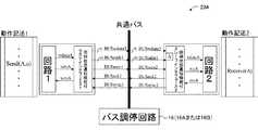
図2は、図1のバス通信システムにおいて、Send命令を実行する側の回路をマスタ回路とするようなバス通信システムの基本構成を示すブロック図である。 FIG. 2 is a block diagram showing a basic configuration of the bus communication system in which the circuit on the side executing the Send instruction is a master circuit in the bus communication system of FIG.
図2に示すように、バス通信システム20Aにおいて、動作記述1は回路1の動作を表す記述であり、回路1でSend(A,a)が実行されることを示している。また、動作記述2は回路2の動作を表す記述であり、回路2でReceive(A)が実行されることを示している。wdataA信号およびrdataA信号は通信データ信号である。また、wtxA信号およびrtxAはSend命令が実行されたことを示す信号(以下、Send命令実行信号という)であり、HighのときにSend命令が実行されたことを示す。さらに、wrxA信号およびrrxA信号はReceive命令が実行されたことを示す信号(以下、Receive命令実行信号という)であり、HighのときReceive命令が実行されたことを示す。 As shown in FIG. 2, in the
共通バス信号は、図15で説明したBUSaddr信号、BUSwdata信号、BUSwen信号およびBUSack信号に加えて、BUSsync信号よって構成される。BUSaddr信号はアドレスを指定するための信号であり、BUSwdata信号は書き込みデータ信号である。また、BUSwen信号は書き込み要求信号であり、Highのときに書き込み要求を出していることを示す。BUSack信号は通信終了信号であり、Highのときにバス転送が終了したことを示す。さらに、BUSsync信号は同期通信転送完了信号であり、Highのときに同期通信のデータ転送が完了したことを示す。BUSsync信号はBUSren信号に含まれていてもよい。 The common bus signal is configured by a BUSsync signal in addition to the BUSaddr signal, the BUSwdata signal, the BUSwen signal, and the BUSack signal described with reference to FIG. The BUSaddr signal is a signal for designating an address, and the BUSwdata signal is a write data signal. The BUSwen signal is a write request signal and indicates that a write request is issued when High. The BUSack signal is a communication end signal, and indicates that the bus transfer has ended when High. Furthermore, the BUSsync signal is a synchronous communication transfer completion signal, and indicates that synchronous communication data transfer has been completed when High. The BUSsync signal may be included in the BUSren signal.
図2のバス通信システム20Aでは、BUSwdata1信号およびBUSwdata2信号が共通バスのBUSwdata信号に接続され、BUSaddr1信号およびBUSaddr2信号が共通バスのBUSaddr信号に接続される。また、BUSwen1信号およびBUSwen2信号が共通バスのBUSwen信号に接続され、BUSack1信号およびBUSack2信号が共通バスのBUSack信号に接続される。さらに、BUSsync1信号およびBUSsync2信号は共通バスのBUSsync信号に接続される。 In the
以下に、図2の回路1とマスタインタフェース1との間の通信と回路2とスレーブインタフェース2との間の通信に、図13および図14のタイミングで示される通信方法を用いた場合について、インタフェースの動作を説明する。ここでは、その一例として、マスタ回路から書き込み要求があったときに、スレーブ回路でデータの受け取り準備ができていなかった場合に、バス転送を終了させるまでのサイクル数を0回(バス転送を即時終了する場合)とする。 In the following, the communication method shown in the timing of FIGS. 13 and 14 is used for communication between the
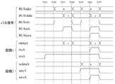
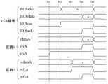
図3は、図2に示すバス通信システム20Aにおいて、同期データの送り出し側の回路が受け取り側の回路よりも先に準備ができて、Send命令がReceive命令よりも先に実行された場合の本実施形態のバス通信方法例を示すタイミング図である。なお、リセット後、BUSwen信号、BUSack信号、BUSsync信号、wtxA信号、wrxA信号、rtxA信号およびrrxA信号の初期値はロウ(Low)レベルとする。 FIG. 3 shows a case where, in the
図3に示すように、まず、T71において、回路1がwtxA信号(Send命令実行信号)をハイ(High)レベルにすると、マスタインタフェース1は、どの同期ポートへの要求かを判断する。T72において、マスタインターフェイス1は、共通バスに対してBUSaddr信号(アドレス指定信号)にアドレスA、BUSwdata信号(書き込みデータ信号)にデータaを送出し、BUSwen信号(書き込み要求信号)をHighにして書き込み処理を実行し、BUSack信号(通信終了信号)がHighになるまで待機する。 As shown in FIG. 3, first, at T71, when the
スレーブインタフェース2は、アドレスAに対する書き込み要求があると判断すると、T73において、直ちにBUSack信号(通信終了信号)を1サイクルの間だけHighにして、バスの通信処理を終了させる。それと同時に、BUSsync信号(同期通信完了信号)にrrxA信号(Receive命令実行信号)の状態を送出する。この場合、rrxA信号(Receive命令実行信号)がLowであるため、受け取り準備ができていないことを意味する。 When determining that there is a write request for the address A, the
一方、マスタインタフェース1は、T73においてBUSack信号(通信終了信号)がHighになると、wrxA信号(Receive命令実行信号)にBUSsync信号(同期通信完了信号)の状態を送出する。この場合、rrxA信号(Receive命令実行信号)がLowであるためBUSsync信号もLowである。このため、wrxA信号(Receive命令実行信号)をLowにする。また、データの送り先がまだ受け取り準備ができていなかったと判断し、T75において再度書き込み処理を実行する。即ち、T75において、T72の場合と同様に、マスタインターフェイス1は、共通バスに対してBUSaddr信号(アドレス指定信号)にアドレスA、BUSwdata信号(書き込みデータ信号)にデータaを送出し、BUSwen信号(書き込み要求信号)をHighにして書き込み処理を実行し、BUSack信号(通信終了信号)がHighになるまで待機する。 On the other hand, when the BUSack signal (communication end signal) becomes High at T73, the
スレーブインタフェース2は、アドレスAに対する書き込み要求があると判断すると、T76において、直ちにBUSack信号(通信終了信号)を1サイクルの間だけHighにして、バスの通信処理を終了させる。それと同時に、BUSsync信号にrrxA信号(Receive命令実行信号)の状態を送出する。この場合、rrxA信号(Receive命令実行信号)はT75からHighであるため、データの受け取りが完了したことを意味する。さらに、rdataA信号にBUSwdata信号のデータaを送出し、rtxA信号(Send命令実行信号)を1サイクルの間だけHighにする。 When determining that there is a write request for the address A, the
マスタインタフェース1は、T76においてBUSack信号(通信終了信号)がHighになると、T77においてBUSsync信号(同期通信完了信号)の状態を判断する。この場合、BUSsync信号(同期通信完了信号)がHighであるため、データの送り先がデータを受け取ったと判断し、書き込み処理を終了する。また、マスタインターフェイス1は、BUSack信号(通信終了信号)がHighであるT76からT77の間、wrxA信号(Receive命令実行信号)にBUSsync信号(同期通信完了信号)の状態を送出する。このとき、BUSsync信号(同期通信完了信号)はHighであるので、wrxA信号(Receive命令実行信号)をHighにする。T77で同期通信が完了する。 When the BUSack signal (communication end signal) becomes High at T76, the
ここで、従来のバス通信システムを用いた場合、T73の時点ではBUSack信号(通信終了信号)はLowのままであり、BUSack信号(通信終了信号)がHighになるのはT76である。よって、T73からT76の間は共通バスが占有されたままであり、この間に他のマスタ回路が共通バスを使用しようとしても、使用することができない。 Here, when the conventional bus communication system is used, the BUSack signal (communication end signal) remains Low at time T73, and the BUSack signal (communication end signal) becomes High at T76. Therefore, the common bus remains occupied from T73 to T76, and even if another master circuit tries to use the common bus during this period, it cannot be used.
これに対して、本実施形態によれば、T74の時点でバスを一旦開放しているので、他のマスタ回路に占有権を与えることが可能であり、デッドロックを起こさず、バスをより有効に利用することができる。 On the other hand, according to the present embodiment, since the bus is opened once at T74, it is possible to give the exclusive right to other master circuits, and the bus is more effective without causing deadlock. Can be used.
ここで、デッドロックを起こさずにバスを有効に利用するためには、同じアドレスへのアクセスを行うマスタ回路に対して、連続して占有権を与えないような機能を有するバス調停回路16を設ける。 Here, in order to use the bus effectively without causing a deadlock, the
例えば、通常は予め定められた優先順位が高いマスタ回路から順に占有権を与えて、複数のマスタ回路からバス要求が出されている場合には、予め定められた回数以上占有権を与えたマスタ回路の優先順位を一旦下げることにより、マスタ回路に対して順番にバスの占有権を与える方法(図4)や、ランダムにバスの占有権を与える方法(図5)などが挙げられる。 For example, normally, when an exclusive right is given in order from a master circuit having a predetermined priority, and a bus request is issued from a plurality of master circuits, a master that has given the exclusive right more than a predetermined number of times. There are a method of giving the bus exclusive right in order to the master circuit (FIG. 4), a method of randomly giving the bus exclusive right (FIG. 5), etc. by lowering the priority of the circuit once.
図4は、図1のバス調停回路16において、バスの占有権を一旦下げる方法を用いたバス調停回路の構成例を示すブロック図である。 FIG. 4 is a block diagram showing a configuration example of a bus arbitration circuit using a method for temporarily reducing the bus occupation right in the
図4に示すように、バス調停回路16Aは、マスタ制御部161A、優先順位設定部162A、優先順位制御部163およびカウンタ164を有している。 As shown in FIG. 4, the bus arbitration circuit 16A includes a
マスタ制御部161Aは、マスタ回路からのバス要求(データ転送要求)の有無を判定し、バス要求が発生していれば、優先順位制御部163から与えられる優先順位が高いマスタ回路に対してバスの占有権を与えるためにバス認可信号を出力する。 The
優先順位設定部162Aは、バス通信システム20内のマスタ回路の優先順位を設定する。 The priority
優先順位制御部163は、カウンタ164に接続されており、どのマスタ回路に占有権が与えられているかを監視して、連続して同じマスタ回路に占有権が与えられた場合に、その回数をカウンタ164によってカウントする。そのカウントされたカウント値が予め定められた回数(所定回数)になると、占有権が与えられているマスタ回路の優先順位を一番低くする。 The
図5は、図1のバス調停回路16において、バスの占有権をランダムに与える方法を用いたバス調停回路の構成例を示すブロック図である。 FIG. 5 is a block diagram showing a configuration example of a bus arbitration circuit using a method of randomly giving the bus occupation right in the
図5に示すように、バス調停回路16Bは、マスタ制御部161B、優先順位設定部162B、カウンタ164および乱数発生部165を有している。 As illustrated in FIG. 5, the
マスタ制御部161Bは、マスタ回路からのバス要求(データ転送要求)の有無を判定し、バス要求が発生していれば、優先順位設定部162Bから与えられる優先順位が高いマスタ回路に対してバスの占有権を与えるためにバス認可信号を出力する。また、マスタ制御部161Bは、カウンタ164に接続されており、どのマスタ回路に占有権が与えられているかを監視して、連続して同じマスタ回路に占有権が与えられた場合に、その回数をカウンタ164によってカウントする。そのカウントされたカウント値が予め定められた回数(所定回数)になると、優先順位に関係なく、乱数生成部165から与えられる乱数値により、ランダムにマスタ回路に対してバスの占有権を与えるためにバス認可信号を出力する。 The
優先順位設定部162Bは、バス通信システム20内のマスタ回路の優先順位を設定する。 The priority
乱数生成部165は、バス通信システム20内において同期通信を行うマスタ回路の数の範囲内で乱数を生成する。 The random
図6は、図2に示すバス通信システム20Aにおいて、同期データの受け取り側の回路が送り出し側の回路よりも先に準備ができて、Receive命令がSend命令よりも先に実行された場合の通信方法例を示すタイミング図である。なお、リセット後、BUSwen信号、BUSack信号、BUSsync信号、wtxA信号、wrxA信号、rtxA信号およびrrxA信号の初期値はLowとする。 FIG. 6 shows communication in the
図6に示すように、まず、T81において、回路2がrrxA信号(Receive命令実行信号)をHighにすると、スレーブインタフェース2は、アドレスAへの書き込み要求があるまで待機する。 As shown in FIG. 6, first, at T81, when the
次に、T84において、回路1がwtxA信号(Send命令実行信号)をHighにすると、マスタインタフェース1は、どの同期ポートへの要求か判断する。 Next, at T84, when the
さらに、T85において、マスタインターフェイス1は、共通バスに対してBUSaddr信号にアドレスA、BUSwdata信号にデータaを送出し、BUSwen信号(書き込み要求信号)をHighにして、BUSack信号(通信終了信号)がHighになるまで待機する。 Further, at T85, the
スレーブインタフェース2は、アドレスAへの書き込み要求があると判断すると、T86において直ちにBUSack信号(通信終了信号)を1サイクルの間だけHighにする。それと同時に、BUSsync信号(同期通信完了信号)にrrxA信号(Receive命令実行信号)の状態を送出する。この場合、rrxA信号(Receive命令実行信号)がHighであるため、データの受け取りが完了したことを意味する。さらに、rdataA信号にBUSwdata信号のデータaを送出し、rtxA信号(Send命令実行信号)を1サイクルの間だけHighにする。 When determining that there is a write request to the address A, the
マスタインタフェース1は、T86においてBUSack信号(通信終了信号)がHighになると、wrxA信号(Receive命令実行信号)にBUSsync信号(同期通信完了信号)の状態を送出する。このとき、BUSsync信号(同期通信完了信号)はHighであるので、wrxA信号(Receive命令実行信号)をHighにする。また、マスタインターフェイス1は、BUSsync信号(同期通信完了信号)の状態を判断し、BUSsync信号(同期通信完了信号)がHighであるため、データの送り先がデータを受け取ったと判断し、書き込み処理を終了する。T87で同期通信が完了する。 When the BUSack signal (communication end signal) becomes High at T86, the
上記図3および図6に示す例において、マスタ回路がすぐにバスの占有権が得られない場合でも、バスの占有権が得られるまで、wrx信号をLowにしておけば、同様に同期通信が可能である。 In the example shown in FIG. 3 and FIG. 6, even if the master circuit cannot obtain the right to occupy the bus immediately, if the wrx signal is set low until the right to occupy the bus is obtained, synchronous communication is similarly performed. Is possible.
図7は、図1のバス通信システムにおいて、Receive命令を実行する側の回路をマスタ回路とするようなバス通信システムの基本構成を示すブロック図である。 FIG. 7 is a block diagram showing a basic configuration of the bus communication system in which the circuit on the side executing the Receive instruction is the master circuit in the bus communication system of FIG.
図7に示すように、動作記述1は回路1の動作を表す記述であり、回路1でReceive(A)が実行されることを示している。また、動作記述2は回路2の動作を表す記述であり、回路2でSend(A,a)が実行されることを示している。wdataA信号およびrdataA信号は通信データ信号である。また、wtxA信号およびrtxAはSend命令が実行されたことを示す信号(以下、Send命令実行信号という)であり、HighのときにSend命令が実行されたことを示す。さらに、wrxA信号およびrrxA信号はReceive命令が実行されたことを示す信号(以下、Receive命令実行信号という)であり、HighのときReceive命令が実行されたことを示す。 As shown in FIG. 7, the
共通バス信号は、図19で説明したBUSaddr信号、BUSrdata信号、BUSren信号およびBUSack信号に加えて、BUSsync信号よって構成される。BUSaddr信号はアドレスを指定するための信号(以下、アドレス指定信号という)であり、BUSrdata信号は読み出しデータ信号である。また、BUSren信号は読み出し要求信号であり、Highのときに読み出し要求を出していることを示す。BUSack信号は通信終了信号であり、Highのときにバス転送が終了したことを示す。さらに、BUSsync信号は同期通信完了信号であり、Highのときに同期通信のデータ転送が完了したことを示す。BUSsync信号はBUSren信号に含まれていてもよい。 The common bus signal includes a BUSsync signal in addition to the BUSaddr signal, the BUSrdata signal, the BUSren signal, and the BUSack signal described with reference to FIG. The BUSaddr signal is a signal for designating an address (hereinafter referred to as an address designating signal), and the BUSrdata signal is a read data signal. The BUSren signal is a read request signal and indicates that a read request is issued when the signal is High. The BUSack signal is a communication end signal, and indicates that the bus transfer has ended when High. Further, the BUSsync signal is a synchronous communication completion signal, and indicates that the data transfer of the synchronous communication is completed when High. The BUSsync signal may be included in the BUSren signal.
図7のバス通信システム20Bでは、BUSrdata1信号およびBUSrdata2信号が共通バスのBUSrdata信号に接続され、BUSaddr1信号およびBUSaddr2信号が共通バスのBUSaddr信号に接続されている。また、BUSren1信号およびBUSren2信号が共通バスのBUSren信号に接続され、BUSack1信号およびBUSack2信号が共通バスのBUSack信号に接続されている。さらに、BUSsync1信号およびBUSsync2信号は共通バスのBUSsync信号に接続されている。 In the
以下に、回路1とマスタインタフェース1との間の通信に図13の方法を用い、回路2とスレーブインタフェース2との間の通信に図14の方法を用いた場合について、インタフェース部の動作を説明する。ここでは、その一例として、マスタ回路から読み出し要求があったときに、スレーブ回路でデータの読み出し準備ができていなかった場合に、バス転送を終了させるまでのサイクル数を0回(バス転送を即時終了)とする。 The operation of the interface unit will be described below in the case where the method of FIG. 13 is used for communication between the
図8は、図7に示すバス通信システム20Bにおいて、同期データの送り出し側の回路が受け取り側の回路よりも先に準備ができて、Send命令がReceive命令よりも先に実行された場合の通信方法例を示すタイミング図である。なお、リセット後、BUSren信号、BUSack信号、BUSsync信号、wtxA信号、wrxA信号、rtxA信号およびrrxA信号の初期値はLowとする。 FIG. 8 shows communication in the
図8に示すように、まず、T91において、回路2がwtxA信号(Send命令実行信号)をHighにすると、スレーブインタフェース2は、アドレスAへの書き込み要求があるまで待機する。 As shown in FIG. 8, first, at T91, when the
次に、T94において、回路1がrrxA信号(Receive命令実行信号)をHighにすると、マスタインタフェース1は、どの同期ポートへの要求か判断する。T95において、マスタインターフェイス1は、共通バスに対してBUSaddr信号にアドレスAを送出し、BUSren信号(読み出し要求信号)をHighにして、BUSack信号(通信終了信号)がHighになるまで待機する。 Next, at T94, when the
スレーブインタフェース2は、アドレスAへの読み出し要求があると判断すると、T96において直ちにバスの通信処理を終了させるため、BUSack信号(通信終了信号)を1サイクルの間だけHighにし、wdata信号のデータaをBUSrdata信号に送出する。それと同時に、BUSsync信号(同期通信完了信号)にwtxA信号(Send命令実行信号)の状態を送出する。この場合、wtxA信号(Send命令実行信号)がHighであるため、データの送信が完了したことを意味する。さらに、wrxA信号(Receive命令実行信号)を1サイクルの間だけHighにする。 When the
マスタインタフェース1は、T96においてBUSack信号(通信終了信号)がHighになると、rtxA信号(Send命令実行信号)にBUSsync信号(同期通信完了信号)の状態を送出する。このとき、BUSsync信号(同期通信完了信号)はHighであるので、rtxA信号(Send命令実行信号)をHighにする。さらに、マスタインターフェイス1は、BUSrdata信号のデータaをrdata信号に送出し、BUSsync信号(同期通信完了信号)の状態を判断して、BUSsync信号(同期通信完了信号)がHighであるため、読み出し処理を終了する。T97で同期通信が完了する。 When the BUSack signal (communication end signal) becomes High at T96, the
図9は、図7に示すバス通信システム20Bにおいて、同期データの受け取り側の回路が送り出し側の回路よりも先に準備ができて、Receive命令がSend命令よりも先に実行された場合の通信方法例を示すタイミング図である。なお、リセット後、BUSren信号、BUSack信号、BUSsync信号、wtxA信号、wrxA信号、rtxA信号およびrrxA信号の初期値はLowレベルとする。 FIG. 9 shows communication in the
図9に示すように、まず、T101において、回路1がrrxA信号(Receive命令実行信号)をHighにすると、マスタインタフェース1は、どの同期ポートからの要求かを判断する。T102において、マスタインターフェイス1は、共通バスに対してBUSaddr信号にアドレスAを送出し、BUSren信号(読み出し要求信号)をHighにして読み出し処理を実行し、BUSack信号(通信終了信号)がHighになるまで待機する。 As shown in FIG. 9, first, at T101, when the
スレーブインタフェース2は、アドレスAに対する読み出し要求があると判断すると、T103において、直ちにBUSack信号(通信終了信号)を1サイクルの間だけHighにして、バスの通信処理を終了させる。それと同時に、BUSsync信号(同期通信完了信号)にwtxA信号(Send命令実行信号)の状態を送出する。この場合、wtxA信号(Send命令実行信号)がLowであるため、読み出しデータがまだ準備できていないことを意味する。 When determining that there is a read request for the address A, the
マスタインタフェース1では、T103でBUSack信号(通信終了信号)がHighになると、rtxA信号(Send命令実行信号)にBUSsync信号(同期通信完了信号)の状態を送出する。この場合、BUSsync信号(同期通信完了信号)はLowであるため、rtxA信号(Send命令実行信号)をLowにする。また、データの読み出し準備ができていなかったと判断し、T105で再度読み出し処理を実行する。即ち、T105で、マスタインターフェイス1は、共通バスに対してBUSaddr信号にアドレスAを送出し、BUSren信号(読み出し要求信号)をHighにして読み出し処理を実行し、BUSack信号(通信終了信号)がHighになるまで待機する。 In the
一方、スレーブインタフェース2は、アドレスAへの読み出し要求があると判断すると、T106で直ちにバスの通信処理を終了させるため、BUSack信号(通信終了信号)を1サイクルの間だけHighにし、wdata信号のデータaをBUSrdata信号に送出する。これと同時に、BUSsync信号(同期通信完了信号)にwtxA信号(Send命令実行信号)の状態を送出する。この場合、wtxA信号(Send命令実行信号)がHighであるため、データの送信が完了したことを意味する。さらに、wrxA信号(Receive命令実行信号)を1サイクルの間だけHighにする。 On the other hand, when the
マスタインタフェース1は、T106でBUSack信号(画像終了信号)がHighになると、rtxA信号(Send命令実行信号)にBUSsync信号(同期通信完了信号)の状態を送出する。このとき、BUSsync信号(同期通信完了信号)はHighであるので、rtxA信号(Send命令実行信号)をHighにする。さらに、マスタインターフェイス1は、BUSrdata信号のデータaをrdata信号に送出し、BUSsync信号(同期通信完了信号)の状態を判断して、BUSsync信号(同期通信完了信号)がHighであるため、読み出し処理を終了する。T107で同期通信が完了する。 When the BUSack signal (image end signal) becomes High at T106, the
上記図7および図9に示す例において、マスタ回路がすぐにバスの占有権が得られない場合でも、バスの占有権が得られるまで、rtx信号をLowにしておけば、同様に同期通信が可能である。 In the example shown in FIG. 7 and FIG. 9, even if the master circuit cannot obtain the right to occupy the bus immediately, if the rtx signal is kept low until the right to occupy the bus is obtained, synchronous communication is similarly performed. Is possible.
以上では、一つの回路がマスタインターフェイスまたはスレーブインタフェースの一方を有する例について説明したが、一つの回路内にマスタインタフェースとスレーブインタフェースの両方を有する構成も可能である。 In the above, an example in which one circuit has one of a master interface and a slave interface has been described. However, a configuration having both a master interface and a slave interface in one circuit is also possible.
また、一つのマスタ回路から複数の同期ポートを用いた同期通信によって、スレーブインタフェースに対して複数の同期ポートへの読み出し要求または書き込み要求が同時に生じるような場合には、マスタインタフェース内に内部調停回路を設けて、同じ同期ポートに対して予め定められた回数以上アクセスが続かないように調停することが好ましい。 In addition, when a synchronous request using a plurality of synchronization ports from one master circuit causes simultaneous read requests or write requests to a plurality of synchronization ports to the slave interface, an internal arbitration circuit is provided in the master interface. It is preferable to arbitrate so that the same synchronization port is not accessed more than a predetermined number of times.
例えば、通常は予め定められた優先順位が高いデータ転送から順にデータ転送を実行し、複数のデータ転送要求が出されている場合には、予め定められた回数以上実行したデータ転送の優先順位を一旦下げることにより、アクセスされる同期ポートを順番に変化させてデータ転送を順番に行う方法や、ランダムにデータ転送を行う方法などが挙げられる。 For example, normally, data transfer is executed in order from a data transfer with a predetermined high priority, and when a plurality of data transfer requests are issued, the priority of the data transfer executed over a predetermined number of times is set. For example, a method of performing data transfer in order by changing the synchronization port to be accessed in order by changing the access port once, a method of performing data transfer at random, and the like.
図10は、問題が生じた図22の従来のバス通信システム構成に対応して、本発明のバス通信システムを適用したシステム構成を示すブロック図である。 FIG. 10 is a block diagram showing a system configuration to which the bus communication system of the present invention is applied in response to the conventional bus communication system configuration of FIG. 22 in which a problem has occurred.
図10では、Receive側をマスタ回路とする場合の通信方法例について説明する。図10に示すように、このバス通信システムでは、回路1でReceive(A)の命令が実行され、回路3でReceive(B)の命令が実行され、回路2ではSend(A,a)の命令が実行された後に、Send(B,b)の命令が実行される。 FIG. 10 illustrates an example of a communication method when the Receive side is a master circuit. As shown in FIG. 10, in this bus communication system, the Receive (A) instruction is executed in the
本発明のバス通信システムによれば、回路1よりも先に回路3のReceive命令が実行され、バス調停回路16からマスタインタフェース3にバスの占有権が与えられて同期ポートBに対してデータの読み出し要求が行なわれた場合でも、データ読み出し先のスレーブインタフェース2ではデータの送信準備ができていないことを通知する応答信号を返すため、バス通信は一旦完了する。 According to the bus communication system of the present invention, the Receive instruction of the
この間に、マスタインタフェース1から同期ポートAに対する読み出し要求が出されて、調停回路16によってマスタインタフェース1に占有権が与えられると、スレーブインタフェース2が同期ポートAに対する読み出し要求を待っている状態であれば、同期ポートAによる同期通信が確立し、これに続いて同期ポートBによる同期通信も確立することが可能となるため、デッドロックが起こることはない。 During this time, when a read request for the synchronous port A is issued from the
以上により、本発明の実施形態によれば、スレーブインターフェイス2は、マスタ回路からデータ転送要求を受けたときにデータ転送可能であれば、直ちにバス転送の終了とデータ転送の完了をスレーブインターフェイス1側に通知し、データ転送が可能でなければ、予め定められたサイクル数だけ待った後、データ転送が更に可能でなければ、バス転送の終了とデータ転送が可能でないことを通知する。待っている途中で転送可能になれば、直ちにバス転送の終了とデータ転送の完了とを通知する。このとき、バス調停回路16は、複数のマスタ回路から転送要求が出されたときに、同じアドレスに転送要求しているマスタ回路に、連続して予め定められた回数以上、バスの占有権を与えないように調停する。これによって、共通バスにより回路間の配線を少なくし、従来は生じていたデッドロックを防いで、より効率よく同期通信を行うことができる。 As described above, according to the embodiment of the present invention, the
以上のように、本発明の好ましい実施形態を用いて本発明を例示してきたが、本発明は、この実施形態に限定して解釈されるべきものではない。本発明は、特許請求の範囲によってのみその範囲が解釈されるべきであることが理解される。当業者は、本発明の具体的な好ましい実施形態の記載から、本発明の記載および技術常識に基づいて等価な範囲を実施することができることが理解される。本明細書において引用した特許、特許出願および文献は、その内容自体が具体的に本明細書に記載されているのと同様にその内容が本明細書に対する参考として援用されるべきであることが理解される。 As mentioned above, although this invention has been illustrated using preferable embodiment of this invention, this invention should not be limited and limited to this embodiment. It is understood that the scope of the present invention should be construed only by the claims. It is understood that those skilled in the art can implement an equivalent range based on the description of the present invention and the common general technical knowledge from the description of specific preferred embodiments of the present invention. Patents, patent applications, and documents cited herein should be incorporated by reference in their entirety, as if the contents themselves were specifically described herein. Understood.
複数の回路間でバスを介して同期通信によりデータ転送を行うバス通信システムの分野において、同期通信を行う回路間に共通バスを設けて回路間の配線を少なくすることができ、必要なときのみ共通バスを占有し、共通バスを占有し続けることがないため、効率よく同期通信を行うバス通信システムを実現することが可能となる。本発明は、複数の回路間で同期通信を行う大規模集積回路に広く適用することが可能である。 In the field of bus communication systems that transfer data by synchronous communication via a bus between multiple circuits, a common bus can be provided between the circuits that perform synchronous communication, reducing the wiring between the circuits, and only when necessary Since the common bus is occupied and does not continue to occupy the common bus, it is possible to realize a bus communication system that performs efficient synchronous communication. The present invention can be widely applied to large-scale integrated circuits that perform synchronous communication between a plurality of circuits.
11 マスタ回路
12〜15 スレーブ回路
11a マスタインターフェイス
12a〜15a スレーブインターフェイス
16,16A,16B バス調停回路
161A,161B マスタ制御部
162A,162B 優先順位設定部
163 優先順位制御部
164 カウンタ
165 乱数発生部
20,20A,20B バス通信システム
11 master circuit 12-15
Claims (9)
Translated fromJapanese複数のマスタ回路から転送要求が出されている場合、連続して同じアドレスに転送要求を出すマスタ回路に対して、連続して予め定められた回数以上、バスの占有権を与えないように調停するバス調停回路が設けられ、
該スレーブ回路は、該マスタ回路から転送要求を受けた場合、該マスタ回路にバス転送終了を通知すると共にデータ転送準備ができているかどうかを通知し、
該マスタ回路は、該データ転送準備ができているとの通知を受けた場合、データ転送処理を終了し、該データ転送準備ができていないとの通知を受けた場合、該スレーブ回路への転送要求を再度実行するものであり、
該スレーブ回路は、該マスタ回路から転送要求を受け、かつ該マスタ回路にデータ転送準備ができていないとの通知をした場合、予め定められたサイクル数だけ待った後、未だデータ転送準備ができていない場合、該マスタ回路にバス転送終了を通知すると共にデータ転送準備ができていないとの通知をし、待っている途中でデータ転送準備ができた場合には、直ちに該マスタ回路にバス転送終了を通知すると共にデータ転送準備ができているとの通知をするバス通信システム。In a bus communication system that enables data transfer by synchronous communication between a master circuit and a slave circuit via a bus,
When transfer requests are issued from multiple master circuits, arbitration is performed so that the master circuit that issues transfer requests to the same address in succession does not give the bus exclusive right more than a predetermined number of times. A bus arbitration circuit is provided,
When the slave circuit receives a transfer request from the master circuit, the slave circuit notifies the master circuit of the end of the bus transfer and notifies whether the data transfer is ready,
When the master circuit receives a notification that the data transfer is ready, the master circuit ends the data transfer process. When the master circuit receives a notification that the data transfer is not ready, the master circuit transfers the data to the slave circuit.is intended to perform the requested again,
When the slave circuit receives a transfer request from the master circuit and notifies the master circuit that the data transfer is not ready, the slave circuit waits for a predetermined number of cycles and is not ready for data transfer yet. If not, the master circuit is notified of the end of the bus transfer and also notified that the data transfer is not ready. If the data transfer is ready while waiting, the bus transfer is immediately completed to the master circuit. And a bus communication systemfor notifying that data transfer is ready .
前記スレーブ回路は、該マスタ回路から前記転送要求としてデータ書き込み要求があった場合、該マスタ回路にバス転送終了を通知すると共にデータ書き込み準備ができているかどうかを通知し、
該マスタ回路は、該スレーブ回路から、データ書き込み準備ができているとの通知を受けた場合、該データ書き込み処理を終了し、該スレーブ回路からデータ書き込み準備ができていないとの通知を受けた場合、該スレーブ回路にデータ書き込み要求を再度出す請求項1または2に記載のバス通信システム。When the master circuit side causes the slave circuit to execute a data write process, in the data transfer process to send the write data from the master circuit and receive the write data in the slave circuit,
When there is a data write request from the master circuit as the transfer request, the slave circuit notifies the master circuit of the completion of the bus transfer and notifies whether the data write is ready,
When the master circuit receives a notification from the slave circuit that the data writing is ready, the master circuit finishes the data writing process and receives a notification from the slave circuit that the data writing preparation is not ready. 3. The bus communication system according to claim 1, wherein the data write request is issued again to the slave circuit.
前記スレーブ回路は、該マスタ回路から前記転送要求としてデータ読み出し要求があった場合、該マスタ回路にバス転送終了を通知すると共にデータ読み出し準備ができているかどうかを通知し、
該マスタ回路は、該スレーブ回路からデータ読み出し準備ができているとの通知を受けた場合、該データ読み出し処理を終了し、該スレーブ回路からデータ読み出し準備ができていないとの通知を受けた場合、該スレーブ回路にデータ読み出し要求を再度出す請求項1または2に記載のバス通信システム。When performing data read processing from the slave circuit from the master circuit side, in the data transfer processing to send read data from the slave circuit and receive read data in the master circuit,
When there is a data read request as the transfer request from the master circuit, the slave circuit notifies the master circuit of the completion of bus transfer and notifies whether the data read is ready,
When the master circuit receives a notification from the slave circuit that data readiness is ready, the master circuit terminates the data read processing and receives a notification from the slave circuit that data readiness is not ready 3. The bus communication system according to claim 1, wherein a data read request is issued again to the slave circuit.
The internal arbitration circuit, when there are a plurality of data transfer requests, assigns a priority to the plurality of data transfer requests, executes the data transfer request in order from the data transfer request with the highest priority, 8. The bus according to claim 7, wherein when the same data transfer request is continuously executed for a predetermined number of times in response to the transfer request, arbitration is performed so that another data transfer request is executed at random regardless of the priority order. Communications system.
Priority Applications (2)
| Application Number | Priority Date | Filing Date | Title |
|---|---|---|---|
| JP2003435840AJP4055903B2 (en) | 2003-12-26 | 2003-12-26 | Bus communication system |
| US11/020,124US20050165988A1 (en) | 2003-12-26 | 2004-12-27 | Bus communication system |
Applications Claiming Priority (1)
| Application Number | Priority Date | Filing Date | Title |
|---|---|---|---|
| JP2003435840AJP4055903B2 (en) | 2003-12-26 | 2003-12-26 | Bus communication system |
Publications (2)
| Publication Number | Publication Date |
|---|---|
| JP2005196306A JP2005196306A (en) | 2005-07-21 |
| JP4055903B2true JP4055903B2 (en) | 2008-03-05 |
Family
ID=34791761
Family Applications (1)
| Application Number | Title | Priority Date | Filing Date |
|---|---|---|---|
| JP2003435840AExpired - Fee RelatedJP4055903B2 (en) | 2003-12-26 | 2003-12-26 | Bus communication system |
Country Status (2)
| Country | Link |
|---|---|
| US (1) | US20050165988A1 (en) |
| JP (1) | JP4055903B2 (en) |
Families Citing this family (2)
| Publication number | Priority date | Publication date | Assignee | Title |
|---|---|---|---|---|
| JP4275085B2 (en)* | 2005-02-17 | 2009-06-10 | 株式会社ソニー・コンピュータエンタテインメント | Information processing apparatus, information processing method, and data stream generation method |
| JP6600518B2 (en)* | 2015-09-28 | 2019-10-30 | ルネサスエレクトロニクス株式会社 | Bus system |
Family Cites Families (17)
| Publication number | Priority date | Publication date | Assignee | Title |
|---|---|---|---|---|
| JP3411300B2 (en)* | 1992-02-18 | 2003-05-26 | 株式会社日立製作所 | Information processing device |
| JPH05324544A (en)* | 1992-05-15 | 1993-12-07 | Hitachi Ltd | Bus control method |
| US6026455A (en)* | 1994-02-24 | 2000-02-15 | Intel Corporation | Architecture and method for providing guaranteed access for a retrying bus master to a data transfer bridge connecting two buses in a computer system |
| US5706446A (en)* | 1995-05-18 | 1998-01-06 | Unisys Corporation | Arbitration system for bus requestors with deadlock prevention |
| US5761445A (en)* | 1996-04-26 | 1998-06-02 | Unisys Corporation | Dual domain data processing network with cross-linking data queues and selective priority arbitration logic |
| US5894562A (en)* | 1996-10-28 | 1999-04-13 | Motorola, Inc. | Method and apparatus for controlling bus arbitration in a data processing system |
| US5896539A (en)* | 1997-04-14 | 1999-04-20 | International Business Machines Corporation | Method and system for controlling access to a shared resource in a data processing system utilizing dynamically-determined weighted pseudo-random priorities |
| JPH10293744A (en)* | 1997-04-18 | 1998-11-04 | Nec Corp | Pci bus system |
| US6006303A (en)* | 1997-08-28 | 1999-12-21 | Oki Electric Industry Co., Inc. | Priority encoding and decoding for memory architecture |
| US6442632B1 (en)* | 1997-09-05 | 2002-08-27 | Intel Corporation | System resource arbitration mechanism for a host bridge |
| GB9719047D0 (en)* | 1997-09-08 | 1997-11-12 | Sgs Thomson Microelectronics | Arbitration system |
| US6073199A (en)* | 1997-10-06 | 2000-06-06 | Cisco Technology, Inc. | History-based bus arbitration with hidden re-arbitration during wait cycles |
| US6199131B1 (en)* | 1997-12-22 | 2001-03-06 | Compaq Computer Corporation | Computer system employing optimized delayed transaction arbitration technique |
| US6397279B1 (en)* | 1998-01-07 | 2002-05-28 | Vlsi Technology, Inc. | Smart retry system that reduces wasted bus transactions associated with master retries |
| US6078338A (en)* | 1998-03-11 | 2000-06-20 | Compaq Computer Corporation | Accelerated graphics port programmable memory access arbiter |
| US7174401B2 (en)* | 2002-02-28 | 2007-02-06 | Lsi Logic Corporation | Look ahead split release for a data bus |
| US7240142B2 (en)* | 2004-10-06 | 2007-07-03 | Tellabs Petaluma, Inc. | Master electronics card with an adaptive bandwidth circuit |
- 2003
- 2003-12-26JPJP2003435840Apatent/JP4055903B2/ennot_activeExpired - Fee Related
- 2004
- 2004-12-27USUS11/020,124patent/US20050165988A1/ennot_activeAbandoned
Also Published As
| Publication number | Publication date |
|---|---|
| JP2005196306A (en) | 2005-07-21 |
| US20050165988A1 (en) | 2005-07-28 |
Similar Documents
| Publication | Publication Date | Title |
|---|---|---|
| JP5231400B2 (en) | Multiprocessor gateway | |
| WO2005091812A2 (en) | Pvdm (packet voice data module) generic bus protocol | |
| TWI662416B (en) | Efficient peer-to-peer communication support in soc fabrics | |
| JP2009538070A (en) | Communication module | |
| US6131135A (en) | Arbitration method for a system with two USB host controllers | |
| JPH10507023A (en) | Shared memory system | |
| JP3769413B2 (en) | Disk array controller | |
| US11652761B2 (en) | Switch for transmitting packet, network on chip having the same, and operating method thereof | |
| CN105988968A (en) | Semiconductor device | |
| US7336700B2 (en) | System bus transceiver interface | |
| US20120124260A1 (en) | CLOSED LOOP DYNAMIC INTERCONNECT BUS ALLOCATION METHOD AND ARCHITECTURE FOR A MULTI LAYER SoC | |
| US7020733B2 (en) | Data bus system and method for performing cross-access between buses | |
| JP4055903B2 (en) | Bus communication system | |
| US9672168B2 (en) | System interconnection of system-on-chip | |
| EP0886218B1 (en) | Time multiplexed scheme for deadlock resolution in distributed arbitration | |
| US7007122B2 (en) | Method for pre-emptive arbitration | |
| EP2588965B1 (en) | Method, apparatus and system for maintaining transaction coherecy in a multiple data bus platform | |
| JPH08314854A (en) | Data transfer system and related apparatus | |
| US20030041176A1 (en) | Data transfer algorithm that does not require high latency read operations | |
| CN115525596A (en) | Multi-master switching high-speed interconnection backplane bus and its control method and processing system | |
| CN112134814A (en) | A board-level interconnection network structure and communication method | |
| JP5028817B2 (en) | Bus system | |
| KR20040032732A (en) | Data bus system and method for performing cross-access between buses | |
| JPH064401A (en) | Memory access circuit | |
| EP1459191B1 (en) | Communication bus system |
Legal Events
| Date | Code | Title | Description |
|---|---|---|---|
| A977 | Report on retrieval | Free format text:JAPANESE INTERMEDIATE CODE: A971007 Effective date:20070628 | |
| A131 | Notification of reasons for refusal | Free format text:JAPANESE INTERMEDIATE CODE: A131 Effective date:20070705 | |
| A521 | Written amendment | Free format text:JAPANESE INTERMEDIATE CODE: A523 Effective date:20070824 | |
| TRDD | Decision of grant or rejection written | ||
| A01 | Written decision to grant a patent or to grant a registration (utility model) | Free format text:JAPANESE INTERMEDIATE CODE: A01 Effective date:20071205 | |
| A61 | First payment of annual fees (during grant procedure) | Free format text:JAPANESE INTERMEDIATE CODE: A61 Effective date:20071205 | |
| R150 | Certificate of patent or registration of utility model | Free format text:JAPANESE INTERMEDIATE CODE: R150 | |
| FPAY | Renewal fee payment (event date is renewal date of database) | Free format text:PAYMENT UNTIL: 20101221 Year of fee payment:3 | |
| FPAY | Renewal fee payment (event date is renewal date of database) | Free format text:PAYMENT UNTIL: 20101221 Year of fee payment:3 | |
| FPAY | Renewal fee payment (event date is renewal date of database) | Free format text:PAYMENT UNTIL: 20111221 Year of fee payment:4 | |
| FPAY | Renewal fee payment (event date is renewal date of database) | Free format text:PAYMENT UNTIL: 20111221 Year of fee payment:4 | |
| FPAY | Renewal fee payment (event date is renewal date of database) | Free format text:PAYMENT UNTIL: 20121221 Year of fee payment:5 | |
| LAPS | Cancellation because of no payment of annual fees |