JP4053619B2 - High power chirp pulse amplifier and compressor - Google Patents
High power chirp pulse amplifier and compressorDownload PDFInfo
- Publication number
- JP4053619B2 JP4053619B2JP15010496AJP15010496AJP4053619B2JP 4053619 B2JP4053619 B2JP 4053619B2JP 15010496 AJP15010496 AJP 15010496AJP 15010496 AJP15010496 AJP 15010496AJP 4053619 B2JP4053619 B2JP 4053619B2
- Authority
- JP
- Japan
- Prior art keywords
- pulse
- chirped
- fiber
- power
- optical
- Prior art date
- Legal status (The legal status is an assumption and is not a legal conclusion. Google has not performed a legal analysis and makes no representation as to the accuracy of the status listed.)
- Expired - Lifetime
Links
Images


Classifications
- H—ELECTRICITY
- H01—ELECTRIC ELEMENTS
- H01S—DEVICES USING THE PROCESS OF LIGHT AMPLIFICATION BY STIMULATED EMISSION OF RADIATION [LASER] TO AMPLIFY OR GENERATE LIGHT; DEVICES USING STIMULATED EMISSION OF ELECTROMAGNETIC RADIATION IN WAVE RANGES OTHER THAN OPTICAL
- H01S3/00—Lasers, i.e. devices using stimulated emission of electromagnetic radiation in the infrared, visible or ultraviolet wave range
- H01S3/05—Construction or shape of optical resonators; Accommodation of active medium therein; Shape of active medium
- H01S3/06—Construction or shape of active medium
- H01S3/063—Waveguide lasers, i.e. whereby the dimensions of the waveguide are of the order of the light wavelength
- H01S3/067—Fibre lasers
- H01S3/06708—Constructional details of the fibre, e.g. compositions, cross-section, shape or tapering
- H—ELECTRICITY
- H01—ELECTRIC ELEMENTS
- H01S—DEVICES USING THE PROCESS OF LIGHT AMPLIFICATION BY STIMULATED EMISSION OF RADIATION [LASER] TO AMPLIFY OR GENERATE LIGHT; DEVICES USING STIMULATED EMISSION OF ELECTROMAGNETIC RADIATION IN WAVE RANGES OTHER THAN OPTICAL
- H01S3/00—Lasers, i.e. devices using stimulated emission of electromagnetic radiation in the infrared, visible or ultraviolet wave range
- H01S3/005—Optical devices external to the laser cavity, specially adapted for lasers, e.g. for homogenisation of the beam or for manipulating laser pulses, e.g. pulse shaping
- H01S3/0057—Temporal shaping, e.g. pulse compression, frequency chirping
- H—ELECTRICITY
- H01—ELECTRIC ELEMENTS
- H01S—DEVICES USING THE PROCESS OF LIGHT AMPLIFICATION BY STIMULATED EMISSION OF RADIATION [LASER] TO AMPLIFY OR GENERATE LIGHT; DEVICES USING STIMULATED EMISSION OF ELECTROMAGNETIC RADIATION IN WAVE RANGES OTHER THAN OPTICAL
- H01S3/00—Lasers, i.e. devices using stimulated emission of electromagnetic radiation in the infrared, visible or ultraviolet wave range
- H01S3/05—Construction or shape of optical resonators; Accommodation of active medium therein; Shape of active medium
- H01S3/06—Construction or shape of active medium
- H01S3/063—Waveguide lasers, i.e. whereby the dimensions of the waveguide are of the order of the light wavelength
- H01S3/067—Fibre lasers
- H01S3/06708—Constructional details of the fibre, e.g. compositions, cross-section, shape or tapering
- H01S3/06729—Peculiar transverse fibre profile
- H—ELECTRICITY
- H01—ELECTRIC ELEMENTS
- H01S—DEVICES USING THE PROCESS OF LIGHT AMPLIFICATION BY STIMULATED EMISSION OF RADIATION [LASER] TO AMPLIFY OR GENERATE LIGHT; DEVICES USING STIMULATED EMISSION OF ELECTROMAGNETIC RADIATION IN WAVE RANGES OTHER THAN OPTICAL
- H01S3/00—Lasers, i.e. devices using stimulated emission of electromagnetic radiation in the infrared, visible or ultraviolet wave range
- H01S3/05—Construction or shape of optical resonators; Accommodation of active medium therein; Shape of active medium
- H01S3/06—Construction or shape of active medium
- H01S3/063—Waveguide lasers, i.e. whereby the dimensions of the waveguide are of the order of the light wavelength
- H01S3/067—Fibre lasers
- H01S3/06754—Fibre amplifiers
- H—ELECTRICITY
- H01—ELECTRIC ELEMENTS
- H01S—DEVICES USING THE PROCESS OF LIGHT AMPLIFICATION BY STIMULATED EMISSION OF RADIATION [LASER] TO AMPLIFY OR GENERATE LIGHT; DEVICES USING STIMULATED EMISSION OF ELECTROMAGNETIC RADIATION IN WAVE RANGES OTHER THAN OPTICAL
- H01S3/00—Lasers, i.e. devices using stimulated emission of electromagnetic radiation in the infrared, visible or ultraviolet wave range
- H01S3/09—Processes or apparatus for excitation, e.g. pumping
- H01S3/091—Processes or apparatus for excitation, e.g. pumping using optical pumping
- H01S3/094—Processes or apparatus for excitation, e.g. pumping using optical pumping by coherent light
- H01S3/094003—Processes or apparatus for excitation, e.g. pumping using optical pumping by coherent light the pumped medium being a fibre
- Y—GENERAL TAGGING OF NEW TECHNOLOGICAL DEVELOPMENTS; GENERAL TAGGING OF CROSS-SECTIONAL TECHNOLOGIES SPANNING OVER SEVERAL SECTIONS OF THE IPC; TECHNICAL SUBJECTS COVERED BY FORMER USPC CROSS-REFERENCE ART COLLECTIONS [XRACs] AND DIGESTS
- Y10—TECHNICAL SUBJECTS COVERED BY FORMER USPC
- Y10S—TECHNICAL SUBJECTS COVERED BY FORMER USPC CROSS-REFERENCE ART COLLECTIONS [XRACs] AND DIGESTS
- Y10S372/00—Coherent light generators
- Y10S372/703—Optical isolater
Landscapes
- Physics & Mathematics (AREA)
- Electromagnetism (AREA)
- Engineering & Computer Science (AREA)
- Plasma & Fusion (AREA)
- Optics & Photonics (AREA)
- Lasers (AREA)
Description
Translated fromJapanese【0001】
【発明の属する技術分野】
本発明は、超短光パルスのチャープパルス増幅装置の技術分野に属し、特に、クラッドが励起されたファイバーを使用する高出力なチャープパルス増幅と、そのコンプレッサーとに関する。
【0002】
【従来の技術】
希土類でドーブされた単一モードのファイバーは、1985年にはじめて製造されて以来、最も広く使われている固体レーザーメディア(媒体)となった。この主な理由は明らかで、1987年にすでに示されたこのメディアの長距離通信装置のための光学増幅器としてのすぐれた性能にある。希土類ドープ・ファイバーは、また、より高度な応用例、例えば、革命的な電気通信装置として期待されているソリトン・ベースの通信装置用の増幅器にも使われている。
【0003】
初期には、連続波レーザー源として、これらファイバーの性能を最適化する研究がなされた。希土類ドープ・ファイバーレーザーの連続波を最適化する努力はまた、スニッツァーその他の米国特許4815079に開示されている様に、高出力を得るための簡単なデバイスとしての二重クラッドファイバー構造の提案をも生んだ。
【0004】
二重クラッドファイバー構造では、ポンプ源として低輝度ダイオードアレイが使用でき、ポンプ光は、ファイバーの芯(コア)でなくて、クラッドの中へ入射される。かくして、マルチモードのダイオードレーザーから単一モードのファイバーレーザーへの輝度変換が高効率で達成されている。クラッドポンプのファイバーレーザーのたった1つの短所は、コア寸法対クラッド寸法の比率により有効吸収(effective absorption)が減少することで、この有効吸収は通常1:100程度の減少比である。したがって、(二重クラッドファイバー構造で)高効率なファイバーレーザーを作るためには、単一クラッドのファイバー構造の100倍の長さのファイバーを使わねばならない。
【0005】
前記の応用例のいずれにおいても、単一モードの希土類ドープ・ファイバーから高エネルギーで高ピークパワーのパルスを引き出すということについては、考慮されていない。これらの従来技術にあっては、レーザー信号は連続波である。その他の従来技術のクラッドポンプ装置は、数pJのエネルギーの数10ピコセカンドの幅をもった信号を増幅するものである(例えば、ソリトン通信装置等)。
【0006】
しかしながら、非線形の光学的応用のための実用的な光源としてファイバーレーザーを考える場合、これらの連続波や準連続波装置が発生するパワーレベルは不充分である。たとえば、典型的な高効率光学的パラメーター発振器には、パルスエネルギー約10nJのサブピコセカンドのパルスが必要である。かくして、これらの増幅器の長さの故に、広い範囲の「許容できない非線形効果」が生じ、また、1kWをこえるピークパワーをもったパルスの入手が妨げられる。それゆえ、二重クラッドポンプファイバーレーザーをその様な装置に導入すると、作動に悪影響が出る。
【0007】
それでも、超高速技術を実用化するためには、小型で一体型のユニットにより、超短(フェムトセカンドからピコセカンド)で高エネルギー(ナノジュールからマイクロジュール)で平均パワーの高い(100mW〜1W)パルスを発生させることが、キーテクノロジーとして肝要である。さらに、商業的に成功するには、この様なデバイスは、比較的低コストで量産に適しておらねばならず、しかも頑丈なものでなければならない。
【0008】
以上の特性を実現するために、超短光パルスのファイバーレーザーと小型半導体とが開発されている。さらに、これらのデバイスを作動させるために、超短パルス発生技術その他の技術が開発された。たとえば、放出波長の高速チューニング、ゲインースイッチングまたはモードロッキングを使い、半導体レーザーダイオードから、ピコセカンドやフェムトセカンドのパルスを発生させることができる。ただし今のところでは、ファイバーレーザーからのフェムトセカンドおよびピコセカンドのパルスの発生は、モードロッキングによってのみ可能である。
【0009】
ハイブリッド(上記技術の複合)のアプローチもまた可能である。その場合、まず高速チューニングまたはゲインスイッチされたレーザーダイオードで、先ず長いパルスを発生させ、次にそれを、光ファイバーまたはファイバー増幅器を使ってソリトン効果により、短くしている。
従来技術としての前述の技術開発については、次の複数の文献(1〜5)に報告されている。
1. A.ガルバナスカス他による「ダイオードレーザーおよびファイバーベース装置によるナノジュールエネレギーのフェムトセカンド光パルスの発生」、アプライド・フィジックスレター、1993年9月27日。
2. N.ステルマクその他による「Q−スイッチされた連続波入射のAlGaAsレーザーからの超短パルス発生」、同誌1991年8月5日。
3. P.デルフィットその他による「ハイブリッドモードロックされた半導体ダイオードレーザー/増幅器装置による200fs光パルスの発生とキャビティー中パルス進化」、オプティックス、1992年5月1日。
4. M.ファーマンによる「単一モード希土類ドープファイバーにもとづく超短パルス源」、アプライド・フィジックス、1993年6月21日。
5. M.ナカザワ他による「配分フィードバックレーザーダイオードによるフェムトセカンド光パルス発生」、エレクトロニックスレターズ、1990年11月20日。
【0010】
前記の方法でこれらのデバイスを作動させると超短パルスは出るが、しかし、多くの実用的応用には、前記の方法によるよりもさらに高いエネルギーと平均パワーをもったパルスが必要である。一般に、半導体レーザー源の最高パワーとパルスエネルギーは、非線形効果、ゲイン飽和および「致命損傷(catastrophic damage)の低い限界値」により、約10mW〜100pJに制限されている。それに反して、ファイバーはマイクロジュールに達するパルスエネルギーと1Wをこえる平均パワーが出せる。しかしながら、モードロックされたファイバーレーザーは特定の条件範囲で、非線形効果に依存するので、限定されたパルスエネルギー(100pJ〜1nJ)および、比較的低い平均パワー(100mW以下)に制限される。ファイバー中でのフェムトセカンドおよびピコセカンドパルスの直接的な増幅も非線形効果の限界値が低いので、約1nJ以下に制限される。
【0011】
チャープパルス増幅(CPA)技術にファイバー増幅器を利用すれば、前述の低いエネルギーおよびパワーの問題を解決できる可能性がある。ファイバー増幅器でのチャープパルス増幅によれば、小型のファイバーおよびレーザーダイオード源のパルスエネルギーおよび平均パワーのレベルを、現在の多くの大型科学レーザーのレベルに引き上げることができる。
【0012】
チャープパルス増幅(CPA)法では、超短パルスが伸長されて増幅されたのち、最終的に伝送の前に再圧縮される。すると、比較的長い持続時間のパルスを伸長することにより、増幅器内でのピークパワーが比較的低く保たれるので、非線形効果とパルスの崩壊とを防ぐことができる。
しかし、光ファイバーとファイバー増幅器の物性のために、ファイバー内でのチャープパルス増幅の実施については、いくつかの解決せねばならぬ問題や制限がある。すなわち、高ピークパワーで生じる非線形効果、ASEで制限されるゲイン、ゲイン幅減少効果による再圧縮された時間の増大、限定されたポンプパワーによる出力パワーの制限、小型コンプレッサー(圧縮器)とストレッチャー(伸長器)との組合せによるパルスの初期時間への再圧縮などの問題や制限である。
【0013】
本発明の発明者らは、以前にも10〜100mWの平均出力パワーで、マイクロジュールのピコセカンドとフェムトセカンドの光パルスのエネルギー増幅にファイバー増幅器つきチャープパルス増幅法を応用した。この研究に関しては、次の文献(6〜7)に記載されている。
6. A.ガルバナスカス、M.E.ファーマン、P.ブリクスト、A.テレクセンおよびD.ハーターによる「高エネルギー超短パルスのハイブリッドダイオード・レーザーファイバー増幅器源」、オプティックスレター19、1043(1994年)。
7. A.ガルバナスカスによる「小型超高出力レーザー装置」、レーザーおよびその応用に関する光学技術協会コンファレンス( Int. Soc. of Optical Engineering conf. on Lasers and Appl.) OE LASE 94, サンノゼ、1995年、原稿番号2377−14。
【0014】
【発明が解決しようとする課題】
高エネルギーパルスを得るための主な方法は、光学ゲートを増幅段の間で使って60dB以上の高ゲインを得ることにあった。パルスは、バルク式コンプレッサーおよびストレッチャーを使って伸長され、再圧縮される。
高パワー超短パルス技術の実施の技術的課題は、ファイバー増幅器の高エネルギーと高パワーの間にトレードオフ関係があること、そしてこれら2つに関する制限が異なることでよく理解できる。
【0015】
エネルギー増幅器はポンプパワーに反して、収容されているエネルギーを効率よく引出す様に設計されている。高パルスエネルギーに高ポンプパワーは必要でない。事実、低い反復率を使って増幅されたパルスの平均出力パワーを犠牲にすることで最高増幅ゲインは保つことができる。これに反して、高パワーの増幅出力をうるためには、ポンプ光の高パワー化と高いパルス反復率での効率のよいパワー抽出が必要である。
【0016】
そこで本発明は、ファイバーチャープパルス増幅により、装置全体の小型サイズと低コストとを維持しながら、100mW〜10Wレベルの高い平均出力パワーを達成する高出力チャープパルス増幅装置を提供することを、解決すべき課題とする。また本発明は、上記高出力チャープパルス増幅装置に使用して好適なコンプレッサーを提供することをも、併せて解決すべき課題とする。
【0017】
【課題を解決するための手段およびその作用・効果】
本発明による解決手段としての装置では、ポンプ用としてマルチモードのダイオードーレーザーを使用しており、クラッドポンプされたファイバーを用いたチャープパルス増幅によって高パワーの出力が達成される。その結果、本発明の高出力チャープパルス増幅装置によれば、高いポンプパワーと高出力パワーとをかなり低コストで得ることができる。本明細書および添付の図面に開示され特許請求されている新規装置は、増幅された光パルスの短い持続時間と品質を保ちながら、クラッドポンプファイバー増幅器のチャープパルス増幅装置との適切な統合を実現するものである。
【0018】
さらに、本明細書等に開示されている実施例は、パルス圧縮のためのハイブリッドファイバー格子と回折格子の組合せを、増幅され再圧縮された超短光パルスの最高ピークパワーを犠牲にすることなく、小型な装置で実現することを示している。以下の実施例には、高パワーレーザーパルスのための高パワーアンプとして二重クラッドファイバー構造の使用を可能にする装置デザインが開示されている。これらの実施例には、いくつかのチャープパルス増幅技術の誘導形式を利用している。
【0019】
すなわち、例えばチャープ・ファイバー・ブラッグ格子(chirped fiber Bragg gratings)を使用するなどして、超短光パルスは、二重クラッド増幅器での増幅に先立って長い「時間的長さ」に分散的に伸長されている。これによって、二重クラッド増幅器内でのピークパワーは低く抑えられており、カー型の非線形性も最小に抑制されている。そして、最初のもの(格子)と反対にチャープされているチャープファイバーブラッグ格子の中で、パルスを再圧縮することで元のパルス幅が復元される。
【0020】
その結果、二重クラッドファイバー構造の高連続波パワー能力は単一モードファイバーの高エネルギー収容能力と組合され、超高ピークパワーおよび超高パルスエネルギーのパルスが、今までにない簡単さで発生される。ここに開示されている本発明の技術は、例えば前記のスニッツァーその他の特許に示されている偏心コア(オフセンターコア)のように特殊なファイバーデザインを、必要とはしていない。本発明の装置では、ファイバーコアは、従来の様にクラッドの中央に置かれていてかまわない。例えば、ポンプ光の導波路として、シリコンゴムなどの低い指数(屈折率)の材料でファイバークラッドを包んでおきさえすればよい。この様なファイバーデザインには、光ファイバー用のアクリレートコートが出現する以前から広く使われていた、低指数(低屈折率)のコートを有する従来のファイバーも含まれている。
【0021】
【発明の実施の形態】
本発明の高出力チャープパルス増幅装置およびコンプレッサーの実施の形態については、当業者に実施可能な理解が得られるよう、以下の実施例等で明確かつ充分に説明する。
〔実施例1および実施例2〕
(二重クラッドファイバー)
先ず、本発明の実施例1としての高出力チャープパルス増幅装置に使用する二重クラッドファイバーについて説明する。
【0022】
図1に、本発明の実施に適する二重クラッドファイバーが示されている。図1に示されているのファイバーは、開口数(Numerical Aperture)の小さい小径をもつ単一モード中央コアC1で芯が形成されている。そして単一モード中央コアC1は、それより大きなマルチモードのコアC2(より大きな開口数のもの)で周囲をとりかこまれている。マルチモード・コアC2は、さらにその周囲を第2のクラッドC3で囲まれており、この第2のクラッドC3の周囲はファイバーコートC4で囲まれている。したがって、マルチモード・コアC2は、単一モードコアC1内に信号を留めておく(逃がさない)ためのクラッディングと、伝搬するポンプ光のためのマルチモード導波路との両方の役割を果たす。一般に、この様なファイバーの断面は、完全に軸対称であってもよいし、前記のスニッツァーその他の特許にあるように何らかの非対称が入ったものでもよい。
【0023】
しかしながら、前述のように非対称性は中央コアのポンプ吸収を強めるために有用ではあるが、本発明者らは、本発明の装置によれば対称なファイバーでも同様の結果が得られることを実験的に発見している。
(従来技術によるポンプおよび増幅器)
連続波装置(CWシステム)においては、二重クラッドファイバーが低輝度ポンプビームを高輝度ビームに変換するために使われてきた。
【0024】
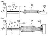
このコンセプトは、図2(a)と図2(b)とに対照的に図示されている。
すなわち、図2(a)に示すように、単一立体モードのポンプダイオード200の出力(単一モードポンプビームSB)は、単一モードファイバー205に結合(カップリング)される。単一モードファイバー205には、単一モードコア210と単一クラッド215とが含まれている。単一モードファイバー205は、その両端で二色性ミラー220によって仕切られている。このような仕組の難点は低いポンプ力の他にもあり、単一モードレーザーダイオード200の出力SBの非対称性と大きな開口数とが、軸対称の低開口数ファイバーのモードと合致しにくいので、高い結合効率が発揮され難い。
【0025】
一方、上記結合効率の向上は、図2(b)に示すように、二重クラッドファイバー230を使用することにより達成できる。図2(b)の仕組では、単一モードダイオード200(図2(a)参照)の代わりに、レーザーダイオードアレイ225を使用する。ダイオードアレイ225の低輝度ポンプビームLBは、二重クラッドファイバー230に入射する。二重クラッドファイバー230の両端も、二色性ミラー220で仕切られている。二重クラッドファイバー230は、図1の二重クラッドファイバーと同じでよい。
【0026】
さらに、図2(b)の仕組みでは、効率の良いポンプビームLBとマルチモードコアC2との結合(カップリング)は、開口数(N.A.)とポンプビームLBおよびマルチモードコアC2の寸法と合わせることにより達成できる。ポンプビームLBは、中央コアC1中の複数の希土類のイオンにより、ファイバー230に沿って(伝搬するうちに)吸収される。2つの二色性ミラー220は、信号の波長では光線の一部を反射しポンプ波長では光線を透過するので、高パワーで低輝度のポンプビームLBは、連続波(Continuous Wave)の高パワーかつ高輝度の単一空間モードビームSSOに変換される。
【0027】
これに対し、従来の単一モードファイバー増幅器は、ポンプ用と単一波長の両方を単一の横方向モードで伝搬するように設計されている。このためにポンプ源は、効率よい単一モードファイバーコアとの結合に適した高品質円形出力ビーム源のみに絞られる。そのようなビーム源(例えば980nmと1480nmのレーザーダイオードMOPAおよびピグテールレーザーダイオード)は、現在のところ、50mW〜1Wのポンプパワーしか出せない。この単一モード源からの最高ポンプパワーは、レーザーの面(ファセット)の致命的損傷(カタストロフィック・ダメージ)のために制限されてしまう。
【0028】
ここで、既存のマルチストライプ・レーザー・ダイオードアレイおよびバーは、10W以上のポンプ力を提供することができ、単一モードのビーム源よりも価格が1ケタ低廉である。しかしながら、幾何学的サイズが大きい発光面のゆえに、輝度が低いこととビームの非対称性とにより、効率よい単一モードファイバーとの結合が阻害されてしまう。
【0029】
(実施例1,2の高出力チャープパルス増幅装置)
本発明の新規な装置においては、この問題はクラッドポンプファイバーの使用によって克服されている。
図3には、実施例1としての単一パスのパワー増幅による二段クラッドポンプチャープパルス増幅装置が示されている。一方、図4には、実施例2としての二重パス・パワーアンプによる装置が示され、図3と同様な要素には同じ符号がつけられている。二重パス・パワーアンプは、後段からより効率的にパワーを抽出するので好適である。
【0030】
図3および図4に示すように、実施例1および実施例2のそれぞれの増幅装置は、チャープパルス源10、プリアンプ段20、パワーアンプ段30a,30b、およびコンプレッサー40(図3には図示せず)から構成されている。また、図3には、ポンプダイオードアレイ50と光学要素60aとが示されており、両者50,60aは、チャープパルス源10からの光をコア70に焦点を結ばせるとともに、ダイオードアレイ50からの光を第1のクラッド80へ入射させるために使われている。この二重パスの仕組と格子コンプレッサー(図略)とを結合する光学的仕組60bには、図4に示すように、偏光ビームスプリッター90と(1/4)波長板100,110とが含まれている。
【0031】
本発明によるチャープパルス増幅(CPA)装置では、図3および図4に示されているように、光学的フィードバックが既知(公知)の方法でなされている。すなわち、単一ビームを単一モードのコアへ入射し、ポンプビームをマルチモードのクラッドへ入射することで同様の輝度変換が達成され、フェムトセカンドまたはピコセカンドの低パワービームは、高パワーのビームに変換される。
【0032】
その結果、本装置による出力パワーの向上は、従来の単一モード形状のファイバーチャープパルス増幅に比べ、1桁以上である。
〔実施例3〕
(格子について)
たとえば、ダイオードレーザーの高速チューニング、または、超短パルス源からのパルスを一対の回折格子またはチャープブラッグ格子で伸長することで、チャープパルスを直接発生させることができる。パルスは、増幅の後に同様のコンプレッサーで再圧縮される。(コンプレッサーには、)もともと頑丈で高信頼性のチャープパルス増幅用の小型全ファイバー回路が使えるので、チャープブラッグ格子の採用が好適である。ただし、現在のところ、ブラッグ格子は光ファイバー内でしか効率よく使用することができないので、増幅され圧縮されたパルスの最高ピークパワーと格子の長さとの間には、トレードオフ関係がある。増幅の後、伸長されたパルスのピークパワーを低く保つためにはパルス長は充分長くあるべきである。したがって、増幅されたパルスのエネルギーはファイバー格子の長さに関係する。一方、ファイバー格子が長いと圧縮された高ピークパワーのパルスとの相互作用区間が長くなり、あるエネルギーレベル(パルスと格子パラメーターとによって異なるが100nJ〜1μJ程度)では、コンプレッサー自身の非線形効果により得られるパルスエネルギーが制限されてしまう。
【0033】
(実施例3のコンプレッサー)
本発明の実施例3としての好適な光学装置(コンプレッサー)は、図5に示すように、ファイバー格子コンプレッサー510および回折格子コンプレッサー520のハイブリッドの組合せが使われている。増幅され伸長されたパルス500は、まず、ファイバーコンプレッサー(510)の非線形効果の限界以下の時間(約10〜50ps)にファイバー格子コンプレッサー510で予備圧縮(プリコンプレス)される。最終的な圧縮は、比較的短いパルスを圧縮するように設計された極めて小型の回折格子コンプレッサー520により実現される。従来の金属反射格子が、回折格子コンプレッサー520として使用できる。ただし、現在入手できる透過回折格子も、反射格子より小型で頑丈な仕組に使えるので好適である。
【0034】
小型の半導体とファイバーレーザー源からの典型的なパワーは、しばしば10〜100μWのレベルであり、これでは100mW〜1Wの出力パワー域で作動するパワーアンプを飽和するには不充分である。したがって、飽和に達して効率よくパワー抽出をするためには、信号レベルが第二段の入力サイドで1〜10mWになるようにプリアンプが必要となる。しかしながら、1〜50mW高出力パワーを発揮する特定のファイバー発振器が設計されており、このパワーはプリアンプなしでパワーアンプを飽和するのに充分な大きさである。
【0035】
本発明の装置は、連続波(cw)信号ではなく、むしろ反復パルスを増幅するものである。それゆえ、両方の増幅段階で光学格子技術を使わずに自然放出の増幅を抑制するためには、その(反復パルスの)反復率が充分に高い(1〜100MHz)ことが必要である。
〔実施例4および実施例5〕
(実施例4および実施例5の概要)
本発明により、実施例4としてのマルチストライプ・ダイオードで励起されたEr/Ybコドープ(codoped)フィバー増幅器によるチャープパルス増幅装置と、実施例5としてのErドープ・クラッド・ポンプファイバー増幅器による高平均パワーチャープパルス増幅装置とが構成される。これらの装置は、それぞれ図6(実施例4)および図7(実施例5)を参照して、下記のように説明される。ただし、これらの実施例はErドープ・ファイバーについて述べられてはいるが、ここに記述されている本発明は、希土類(例えばNd,Tm,Yb,Pr等)ドープのファイバーのいずれにでも応用することができる。
【0036】
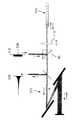
(実施例4の構成と作用)
実施例4は、広い面積のダイオードでポンプされたEr/Ybコドープ二重クラッドファイバーによるピコセカンド・チャープパルス増幅装置である。 発明者らによって考案されたクラッドポンプのピコセカンド・チャープパルス増幅装置の仕組が、実施例4として図6に示されている。本実施例において、増幅ファイバー650の中央コアC1(図1参照)には、ポンプ光Pを効率よく吸収し中央コアC1内で光励起をEr3+イオンに移すために、Yb3+がコドープされている。これにより、大面積のダイオード・レーザーからの高効率ポンプ結合が可能になる。コアのErドープレベルは概ね1000ppmであった。
【0037】
本実施例の特徴は、ポンプ波Pおよび信号波Sを分離/組合せするために、二重クラッドファイバー650の入力端に二色性ミラー655が使われている点である。すなわち、ポンプ光Pを加えるために2つの二色性ミラー655がクラッドポンプ・ファイバー650の一方の端部におかれる。これに対し、従来の単一モードファイバー装置では、ファイバー波長分割マルチプレクサ(Wavelength Division Multiplexer)が使用される。
【0038】
(本実施例の)二重クラッドの場合には、信号光Sが単一モードでありポンプ光Pがマルチモードであるから、標準の波長分割マルチプレクサは使用できない。(ただし、マルチモードのポンプを内側のクラッドへ導き、中央コア内での信号の伝搬を維持する特別設計のマルチモード波長分割マルチプレクサがある。同じ効果を得るために、二色性ミラー以外の方法も使用できる。)
本実施例においては、波長可変(tunable)レーザーダイオード600の放出光Sを直接周波数チャープすることによって、チャープパルスが得られた。この装置は、50〜100mWの平均パワーが得られ、概ね1μJのエネルギーのパルスが得られるように設計された。その二段増幅器の設計により、概ね30dBの大きな信号ゲインと効率よいパワー抽出とが可能になった。
【0039】
第1段増幅器610は、ピグテール・レーザーダイオード630からの波長1.48μmの50mWでポンプされた標準単一モード・Erドープファイバー620を使って組立てられた。第二段パワーアンプ640は、二重パス形式である。100×1μmの光放出面積の1W広域レーザーダイオード(図示せず)が、二色性ミラー655を通して増幅ファイバー650のクラッドに結合されている。(二色性ミラー655では、)波長980nmのポンプ光Pの99%以上が透過され、波長1550nmの信号光Sの98%は反射された。増幅ファイバー650のファイバー長さは5mであった。信号光Sは、二色性ミラー655とその反対側の(増幅ファイバー650の)端部を通して、増幅ファイバー650の中央コア(C1)と結合された。偏光ビームスプリッター690と二つの波長板660,665によって増幅されたビームは、入射ビームから分離され、コンプレッサー670へと送られた。
【0040】
ここで、図6において、波長板660はλ/4デバイスとして示されている。ただし、λ/4−λ/2の配置も使用できる。
コンプレッサー670は回折格子対およびファイバー内チャープブラッグ格子のうちいずれかである。付加的な2つの波長板660,665によりコンプレッサー670から反射されたビームは、装置の出力端へと導かれる。
【0041】
前記の実施例の変形も可能である。たとえば、偏光ビームスプリッター690および波長板(またはファラデー回転子)660,665の仕組は、再入射した光の偏光に影響を与えない(insensitive to polarization)光学アイソレーターで置き換えても良く、置き換えにより仕組みが単純化される。
【0042】
レーザーダイオード600からのパルスのチャープバンド幅は7nmであった。パルスのスペクトルは、増幅ファイバー650のゲインスペクトルの1530nmピークに位置していた。第1段610からの0.5mWの平均パワーは、第二段640を飽和するのに充分であった。
最高出力飽和パワーは、800kHzの反復率で84mWであった。60kHzで、平均パワー60mWでのパルスエネルギーは、0.98μJの最高値に達した。二重パス・クラッドポンプファイバー650の非線型効果の限界(スレッショルド)により、これ以上のパルスエネルギーの増加は制限された。コンプレッサー670を通して50%のパワーが透過した。
【0043】
パワーとパルスエネルギー特性は、A.ガルバナスカスによる「高エネルギー超短パルスのハイブリッドダイオード−レーザーファイバー増幅器源」(オプチックスレター、1994年7月15日)に報告されている、レーザーダイオードMOPAポンプ単一モードファイバー増幅器から得られる特性に近いものであった。
【0044】
本実施例による上記装置の明らかな利点は、パワーアンプのポンプ源のコストが1ケタ低いことである。また、この仕組で使われた1W広域レーザーダイオードは、ほとんど同じコストで、10Wポンプ力以上のはるかに強力なダイオードアレイで置き換えることができる。加えて、この装置の両段ともクラッドポンプ式に設計することもできる。
【0045】
(高出力フェムトセカンド・チャープパルス増幅)
コドープされたファイバーの不利な点は、単一ドープのシリカファイバーに比べて、そのゲインバンド幅と、ポンプからの信号へのパワー変換の効率とが減少することである。さらに、フェムトセカンドのチャープパルス増幅装置でのファイバー増幅器の作動は、狭小バンド幅の信号の増幅よりもはるかに複雑である。広バンド幅フェムトセカンド・パルスの増幅のためのチャープパルス増幅装置は、増幅され再圧縮されたパルスのスペクトル歪みおよび時間歪みを減らすように設計されねばならない。
【0046】
例えば、標準のErドープファイバーのロールオフが1562nm以上であるのに比べて、前記のEr/Ybコドープの装置のゲインスペクトルのロールオフは1543nm以上である。これは、典型的には1550nmより長い波長の近辺にあるモードロックのファイバーレーザーパルスの増幅に、大きく影響する。そのようなパルスの増幅後に、かなりのスペクトルの狭小化と形状変化が起き、その結果再圧縮されたパルスの質が落ちる。
【0047】
ファイバー増幅器のゲインスペクトル(誘導放出断面スペクトル)のゲインのピークに合うようにパルススペクトルが最適に選ばれると、ゲインの狭小化は最小になる。また、同じ目的で、ゲインバンド幅はパルススペクトルよりもはるかに広くするべきである。一つの解決策は、増幅器のスペクトル応答を平滑化するように、ファイバー増幅器を飽和パワー域で作動させることである。この点では、両段とも飽和状態で作動する二段増幅が有利である。また、光学フィルターを使って増幅中にパルススペクトルの形を変え、それによってファイバー増幅器のスペクトル特性に合わせることも可能である。もう1つの解決策は、フラットで幅広いゲインを得るために、または、異なったファイバーを組合せるために、異なった主材料(ホスト)またはドープ剤(ドーパント)を使うことである。
【0048】
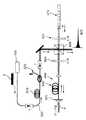
(実施例5の構成および作用)
実施例5では、図7に示すように、フェムトセカンド台の増幅を行うために、ポンプクラッドの直径がコドープ・ファイバーのポンプクラッドの直径より小さい、単一ドープファイバーが使われている。
パワーアンプ700は、高レベルにドープされた(Er3+ドープレベル:100ppm)二重クラッドErファイバー710から構成されている。ここで、中央コアC1(図1参照)のみがErドープされている。内側クラッドは直径が20μmなので、Yb3+をコドープしなくても効率の良いクラッドポンプができる。このファイバー710は、単一ドープのシリカファイバーの幅広いゲインと高いポンプ−信号の変換効率を有している。また、そのゲインスペクトルはこのモードロックファイバー発振器のスペクトルに合致(マッチ)しているので、望ましくないスペクトル狭小化を減らすことができる。ファイバー710は、980nmで1.6Wのトータルパワーを出す2つの極性マルチプレックス単一モードMOPAレーザーダイオード(図示せず)で、ポンプされている。本実施例のクラッドポンプ手段では、単一モードポンプの極めて高効率(約100%)の入力結合が確保される。
【0049】
マルチモードレーザーダイオードビームの効率よい結合は、また、例えばW.クラークソン他による「高出力ダイオードバーのための新規なビーム形成法」(CLEO’94)に開示されたビーム形成法によっても実現できる。
本実施例における単一ドープファイバー使用の利点は、シリカガラス以外の主材料が使えることである。例えば、Erでドープされたフッ化ガラスファイバーも、クラッドの小さい二重クラッドファイバーとして製造できる。このフッ化物主材料は、そのゲインバンド幅がシリカベースのErドープファイバーのそれよりも約2〜3倍であると言う利点を持っている。これは、ゲインの狭小化効果を大きく減少するために極めて重要である。フッ化物のファイバーによれば、チャープパルス増幅装置を通った後のパルスの時間は100fsにも下げられる。
【0050】
図7の仕組において、チャープパルス増幅のパルス源(図示せず)は、調節可能な反復率5〜50MHzで200fsFWHMと20pJエネルギーの初期パルスを出す受動モードロックファイバー発振器である。パルスは、5mmの長さの正チャープされた17nmバンド幅のファイバーブラッグ格子720により、約50psに伸長される。反射されたパルスは、ファイバーピグテール偏光ビームスプリッター(FPBS)740とファイバー偏光コントローラー750(バルクPBSと波長板の代わり)とを使って、プリアンプ730へ入射される。パワーアンプ700の飽和に充分なレベルへ入力パワーを増加させるためには、プリアンプ730が使われる。
【0051】
パワーアンプ700は、前述のEr/Ybコドープ装置と同じ二重パス様式に仕組まれている。第7図の実施例5の特徴は、格子伸長器720とコンプレッサー760の間の装置の中の他のすべてのファイバーの負の分散を補償するために、所定の長さの正分散ファイバーがプリアンプ段730の前に含まれていることである。
【0052】
パワーアンプ700へ入射された平均入力パワーは、10mWに達した。パワーアンプ700は、平均信号パワーを0.45Wのレベルへ強化(ブースト)する。負にチャープされたファイバーブラッグ格子760での再圧縮後、平均出力パワーは0.26Wに達した。この歩留りは、格子の反射率が約80%であることと、格子のファイバーピグテールへの結合効率が約80%であることとの故に、60%に制限された。そして、50MHzの反復率で5.2nJのパルスエネルギーが得られた。反復率を下げると、パルスエネルギーは20nJに増えた。これは、伸長されたパルスの持続時間を非線形効果に抗して維持するためには、最大限のパルスエネルギであった。再圧縮後のパルス幅は380fsであった。初期の200fsのこのパルス時間増大は、ファイバーアンプ700のゲインバンド幅が制限に起因するゲイン狭小化の結果である。
【0053】
第7図の高出力ファイバーチャープパルス増幅装置(CPAシステム)において、各パラメーターは、第二段の終点で非線形効果を除去または減少するように設計されている。適切に設計された装置においては、飽和した出力パワーに対応するパルスフルーエンスは、ファイバーコア内での非線形相互作用の限界におけるフルーエンスよりも小さくあるべきである。高いフルーエンスレベルで生じる非線形性は、(短いパルスの)自己位相変調、(長いパルスの)変調不安定性、および誘導ラマン散乱である。前二者の影響は、光学材料の屈折率の光強度依存性によるものである。これらの一般的影響としてスペクトルの幅広化と位相の非線形性とが誘発され、その結果、再圧縮されたパルスは幅広くなり形状変更される。典型的に言って、サテライトパルス、変調サイドバンドおよびパルスエネルギーのかなりの部分を含む低強度のバックグラウンドが形成される。誘導ラマン散乱は、パルスエネルギーを増幅バンドの外のスペクトルバンドへと散らし、圧縮できない背景とパルスエネルギーの損失とを生じる。
【0054】
(実施例1〜5のまとめ)
本発明の各実施例においては、ファイバー増幅器の長さを減らし、ドープレベルを上げることで非線形の相互作用の長さを減らして、これらの非線形の影響を防いでいる。あわせて、伝搬モードの横方向立体的広がりを大きくしたクラッドポンプファイバーを適切に設計することでその影響を減らし、そして効率の良いパルス伸長を使うことにより、高ピークのパワーを避けている。
【0055】
また、パルスの反復率は、高いパワーレベルでのピーク影響を下げるように調整されている。本発明の各装置では、コドープなしでクラッドを励起する場合、最初のクラッド内でのポンプのはねかえり数(バウンド数)が十分に多くなり、(光線が)ドープされた中央コアを横切る際に効率よく吸収されるよう、ファイバーの長さを充分に長くしておくべきである。このことは、ファイバーの長さ、中央コアのドープレベル、およびクラッドの直径と中央コアの直径との比を適切に選ぶことによってのみ低減される非線形相互作用のためには、ファイバーの長さを短くしたいという要求と、調整(マッチ)することが可能である。
【0056】
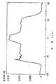
第二段のファイバー710の最適な長さは、ドープレベル1000ppmの場合、3.8mであった。図8には、ファイバー710のポンプクラッドと中央コアの横方向形状とが示されている。中央コアと第1のクラッドの屈折率の差は、標準単一モードファイバーよりも40%大きい横方向モードを与えるように選ばれた。モード直径のこれ以上の増大は、高次オーダーのクラッドモードへの散乱の増大で制限された。この最適化の結果、パルス伸長および再圧縮に使用された5mmの線形にチャープされた(二つの)ファイバー格子が、モードロックパルスの最も高い反復率でもって、充分に低いピークパワーを与えた。上述のパルスとゲインスペクトルとのマッチングに関する考慮のために、格子反射スペクトルはゲインスペクトルのピークと一致するように選ばれた。
【0057】
本発明は特定の前記の実施例によって説明されたが、様々な変形や修正が可能である。したがって、そのような変形、修正のすべてが本発明の範囲に属することがこの分野の専門家に理解されるべきである。
【図面の簡単な説明】
【図1】 クラッドポンプ用の二重クラッドファイバの構造を示す断面図
【図2】 従来技術によるポンプおよび増幅器の構成を示す組図
(a)単一モード型のポンプ装置の模式図
(b)マルチモード型の増幅器の模式図
【図3】 実施例1の高出力チャープパルス増幅装置の構成を示す模式図
【図4】 実施例2の高出力チャープパルス増幅装置の構成を示す模式図
【図5】 実施例3のチャープパルスコンプレッサーの構成を示す模式図
【図6】 実施例4のパルス増幅装置の実験装置の構成を示す模式図
【図7】 実施例5のパルス増幅装置の実験装置の構成を示す模式図
【図8】 実施例3,4用のファイバー特性の横断プロフィール・グラフ
【符号の説明】
C1:単一モード中央コア(芯) C2:マルチモード・コア
C3:第2のクラッド C4:ファイバーコート
SB:単一モードポンプビーム LB:低輝度ポンプビーム
SS:単一モード出力ビーム SSO:単一空間モード出力ビーム
S:信号光(信号波)、放射光 P:ポンプ光(ポンプ波)
200:単一立体モードのポンプダイオード 205:単一モードファイバー
210:単一モードコア 215:単一クラッド 220:二色性ミラー
225:レーザーダイオードアレイ 230:二重クラッドファイバー
10:チャープパルス源 20:プリアンプ段
30a,30b:パワーアンプ段 40:コンプレッサー
50:ポンプダイオードアレイ 60a:光学要素 60b:光学的仕組
70:コア 80:第1のクラッド 90:偏光ビームスプリッター
100,110:(1/4)波長板 500:入力パルス
510:ファイバー格子コンプレッサー 520:回折格子コンプレッサー
600:チューナブル・レーザーダイオード 610:第1段増幅器
620:標準単一モード・Erドープファイバー
630:ピグテール・レーザーダイオード 640:第2段パワーアンプ
650:増幅ファイバー(二重クラッドファイバー) 655:二色性ミラー
660,665:波長板(λ/4デバイス) 670:コンプレッサー
690:偏光ビームスプリッター
700:パワーアンプ 705:二色性ミラー
710:二重クラッドErファイバー 720:格子伸長器
730:プリアンプ 740:ファイバーピグテール偏光ビームスプリッター(FPBS) 750:ファイバー極性コントローラー
760:負にチャープされたファイバーブラッグ格子[0001]
BACKGROUND OF THE INVENTION
The present invention belongs to the technical field of an ultrashort optical pulse chirped pulse amplifying apparatus, and particularly relates to a high-power chirped pulse amplification using a fiber in which a cladding is excited and a compressor thereof.
[0002]
[Prior art]
Single mode fibers doped with rare earths have been the most widely used solid-state laser media since they were first manufactured in 1985. The main reason for this is obvious: its excellent performance as an optical amplifier for the long distance communication device of this media already shown in 1987. Rare earth doped fibers are also used in more advanced applications such as amplifiers for soliton-based communication devices that are expected as revolutionary telecommunication devices.
[0003]
Initially, work was done to optimize the performance of these fibers as a continuous wave laser source. Efforts to optimize the continuous wave of rare-earth doped fiber lasers also proposed a double-clad fiber structure as a simple device to obtain high power, as disclosed in Snitzer et al. US Pat. No. 4,815,079. I was born.
[0004]
In the double clad fiber structure, a low-intensity diode array can be used as a pump source, and the pump light is incident into the clad rather than the fiber core. Thus, luminance conversion from a multimode diode laser to a single mode fiber laser has been achieved with high efficiency. The only disadvantage of the cladding pump fiber laser is that the effective absorption is reduced by the ratio of the core dimension to the cladding dimension, which is usually a reduction ratio of about 1: 100. Therefore, to make a highly efficient fiber laser (with a double clad fiber structure), a
[0005]
In none of the above applications is it considered to extract high energy, high peak power pulses from a single mode rare earth doped fiber. In these prior arts, the laser signal is a continuous wave. Other conventional clad pump devices amplify signals having a width of several tens of picoseconds of energy of several pJ (for example, soliton communication devices).
[0006]
However, nonlinear opticalMeet When considering a fiber laser as a practical light source for use, the power levels generated by these continuous wave and quasi-continuous wave devices are insufficient. For example, a typical high efficiency optical parameter oscillator requires subpicosecond pulses with a pulse energy of about 10 nJ. Thus, due to the length of these amplifiers, a wide range of “unacceptable non-linear effects” occurs, and the availability of pulses with peak power exceeding 1 kW is prevented. Therefore, the introduction of a double clad pump fiber laser into such a device will adversely affect operation.
[0007]
Nevertheless, in order to put ultra-high-speed technology into practical use, a small and integrated unit enables ultra-short (femtosecond to picosecond), high energy (nanojoule to microjoule) and high average power (100mW to 1W). Generating pulses is essential as a key technology. Furthermore, to be commercially successful, such a device must be suitable for mass production at a relatively low cost and must be robust.
[0008]
In order to realize the above characteristics, an ultrashort optical fiber laser and a small semiconductor have been developed. In addition, ultra-short pulse generation techniques and other techniques have been developed to operate these devices. For example, picosecond or femtosecond pulses can be generated from a semiconductor laser diode using fast tuning of the emission wavelength, gain switching or mode locking. However, for now, femtosecond and picosecond pulses from fiber lasers can only be generated by mode locking.
[0009]
A hybrid (combination of the above techniques) approach is also possible. In that case, a long pulse is first generated with a laser diode that is fast-tuned or gain-switched, and then shortened by the soliton effect using an optical fiber or fiber amplifier.
The aforementioned technical development as the prior art is reported in the following documents (1-5).
1. A. “Generation of nanojoule energy femtosecond light pulses by diode laser and fiber-based devices” by Galvanascus et al., Applied Physics Letter, September 27, 1993.
2. N. "Short pulse generation from a Q-switched continuous wave incident AlGaAs laser" by Stelmac et al., August 5, 1991, ibid.
3. P. Delfit et al., “Generation of 200 fs light pulses and evolution of pulses in a cavity with a hybrid mode-locked semiconductor diode laser / amplifier device”, Optics, May 1, 1992.
4). M.M. Furman, “Ultra-short pulse source based on single-mode rare-earth doped fiber”, Applied Physics, June 21, 1993.
5. M.M. "Femtosecond optical pulse generation by distributed feedback laser diode" by Nakazawa et al., Electronic Letters, November 20, 1990.
[0010]
Operating these devices in the manner described above will produce ultrashort pulses, but many practical applications require pulses with higher energy and average power than by the methods described above. In general, the maximum power and pulse energy of a semiconductor laser source is limited to about 10 mW to 100 pJ due to non-linear effects, gain saturation, and “low limit of catastrophic damage”. On the other hand, the fiber can produce pulse energy reaching microjoules and average power exceeding 1W. However, mode-locked fiber lasers are limited to limited pulse energy (100 pJ to 1 nJ) and relatively low average power (100 mW or less) because they depend on nonlinear effects in a specific range of conditions. Direct amplification of femtosecond and picosecond pulses in the fiber is also limited to about 1 nJ or less due to the low limit of nonlinear effects.
[0011]
Chirp pulse amplification (CPA The use of fiber amplifiers in the technology may solve the low energy and power problems described above. Chirped pulse amplification in fiber amplifiers can raise the pulse energy and average power levels of small fiber and laser diode sources to the level of many current large scientific lasers.
[0012]
In the chirped pulse amplification (CPA) method, after ultrashort pulses are expanded and amplified, they are finally recompressed before transmission. Then, by extending the pulse having a relatively long duration, the peak power in the amplifier is kept relatively low, so that nonlinear effects and pulse collapse can be prevented.
However, due to the physical properties of optical fibers and fiber amplifiers, there are several problems and limitations that must be solved when performing chirped pulse amplification in the fiber. That is, non-linear effects caused by high peak power, gain limited by ASE, increase in recompression time due to gain width reduction effect, limited pumppower There are problems and limitations such as limitation of output power due to, and recompression of pulses to the initial time by a combination of a small compressor and a stretcher.
[0013]
The inventors of the present invention have previously applied the chirped pulse amplification method with fiber amplifier to the energy amplification of microjoule picosecond and femtosecond optical pulses with an average output power of 10 to 100 mW. This study is described in the following documents (6-7).
6). A. Galvanuscus, M.M. E. Furman, P.A. Brixto, A. Telexen and D.C. "High energy ultrashort pulse hybrid diode laser fiber amplifier source" by Herter, Optics Letter 19, 1043 (1994).
7). A. Galvanascus “Small Ultra High Power Laser Device”, Int. Soc. Of Optical Engineering conf. On Lasers and Appl. OE LASE 94, San Jose, 1995, manuscript number 2377-14 .
[0014]
[Problems to be solved by the invention]
The main method for obtaining a high energy pulse was to obtain a high gain of 60 dB or more using an optical gate between the amplification stages. The pulses are decompressed and recompressed using a bulk compressor and stretcher.
The technical challenge of implementing high power ultrashort pulse technology is well understood by the trade-off relationship between high energy and high power of the fiber amplifier and the limitations on these two are different.
[0015]
The energy amplifier is designed to efficiently extract the stored energy against the pump power. High pump power is not required for high pulse energy. In fact, the highest amplification gain can be maintained at the expense of the average output power of pulses amplified using a low repetition rate. On the other hand, in order to obtain a high power amplified output,light High powerConversion Efficient power extraction with a high pulse repetition rate is necessary.
[0016]
Accordingly, the present invention solves the problem of providing a high output chirp pulse amplification device that achieves a high average output power of 100 mW to 10 W level while maintaining a small size and low cost of the entire device by fiber chirp pulse amplification. It should be a challenge. Another object of the present invention is to provide a compressor that is suitable for use in the high-power chirped pulse amplification device.
[0017]
[Means for solving the problems and their functions and effects]
In the apparatus as a solution according to the present invention, a multimode diode laser is used for the pump, and the cladding is used.pump High power output can be achieved by chirped pulse amplification using the formed fiber. As a result, according to the high output chirped pulse amplification device of the present invention, high pump power and high output power can be obtained at a considerably low cost. The novel device disclosed and claimed in this specification and the accompanying drawings provides proper integration of the clad pump fiber amplifier with the chirped pulse amplifier while maintaining the short duration and quality of the amplified optical pulse To do.
[0018]
In addition, the embodiments disclosed herein, etc., provide a hybrid fiber grating and diffraction grating combination for pulse compression without sacrificing the highest peak power of amplified and recompressed ultrashort optical pulses. This shows that it can be realized with a small device. The following example discloses a device design that allows the use of a double clad fiber structure as a high power amplifier for high power laser pulses. These embodiments utilize inductive forms of several chirped pulse amplification techniques.
[0019]
That is, for example, using chirped fiber Bragg gratings, ultrashort optical pulses are extended dispersively to a long “time length” prior to amplification in a double-clad amplifier. Has been. As a result, the peak power in the double clad amplifier is kept low, and the Kerr type nonlinearity is also minimized. Then, the original pulse width is restored by recompressing the pulse in a chirped fiber Bragg grating chirped opposite to the first one (grating).
[0020]
As a result, the high continuous-wave power capability of the double-clad fiber structure is combined with the high energy capacity of single-mode fiber, and ultra-high peak power and ultra-high pulse energy pulses are generated with unprecedented ease. The The technology of the present invention disclosed herein does not require a special fiber design, such as the eccentric core (off-center core) shown in the above-mentioned Snitzer et al. In the apparatus of the present invention, the fiber core may be placed at the center of the clad as in the prior art. For example, it is only necessary to wrap the fiber clad with a low index (refractive index) material such as silicon rubber as a waveguide of pump light. Such fiber designs include conventional fibers with low index (low refractive index) coatings that were widely used before the advent of acrylate coatings for optical fibers.
[0021]
DETAILED DESCRIPTION OF THE INVENTION
The embodiments of the high-power chirped pulse amplifying apparatus and the compressor of the present invention will be described clearly and sufficiently in the following examples and the like so that a person skilled in the art can understand which can be implemented.
[Example 1 and Example 2]
(Double clad fiber)
First, a double clad fiber used in the high-power chirped pulse amplifying apparatus as Example 1 of the present invention will be described.
[0022]
FIG. 1 shows a double clad fiber suitable for the practice of the present invention. The fiber shown in FIG. 1 is cored with a single mode central core C1 having a small diameter with a small numerical aperture. The single mode central core C1 is surrounded by a larger multimode core C2 (with a larger numerical aperture). The multi-mode core C2 is further surrounded by a second cladding C3, and the second cladding C3 is surrounded by a fiber coat C4. Therefore, the multimode core C2 serves as both a cladding for keeping a signal in the single mode core C1 (not letting it escape) and a multimode waveguide for propagating pump light. In general, the cross section of such a fiber may be completely axisymmetric or may have some asymmetry as in the above-mentioned Snitzer et al.
[0023]
However, as mentioned above, asymmetry is useful to enhance the pump absorption of the central core, but we have experimentally demonstrated that similar results can be obtained with a symmetric fiber according to the device of the present invention. Have found it.
(Pumps and amplifiers according to the prior art)
In continuous wave devices (CW systems), double clad fibers have been used to convert a low intensity pump beam into a high intensity beam.
[0024]
This concept is illustrated in contrast to FIGS. 2 (a) and 2 (b).
That is, as shown in FIG. 2A, the output (single mode pump beam SB) of the
[0025]
On the other hand, the improvement in the coupling efficiency can be achieved by using a double
[0026]
Further, in the mechanism shown in FIG. 2B, the coupling (coupling) between the efficient pump beam LB and the multimode core C2 is performed by the numerical aperture (NA) and the dimensions of the pump beam LB and the multimode core C2. This can be achieved by combining with The pump beam LB is absorbed along the fiber 230 (as it propagates) by a plurality of rare earth ions in the central core C1. Since the two
[0027]
In contrast, conventional single mode fiber amplifiers are designed to propagate both pump and single wavelength in a single transverse mode. For this reason, the pump source is limited to only a high quality circular output beam source suitable for coupling with an efficient single mode fiber core. Such beam sources (e.g. 980 nm and 1480 nm laser diodes MOPA and pigtail laser diodes) currently can only deliver pump powers between 50 mW and 1 W. The maximum pump power from this single mode source is limited due to catastrophic damage of the laser facet (facet).
[0028]
Here, existing multi-stripe laser diode arrays and bars can provide pump power of 10 W or more, and are one order of magnitude cheaper than single mode beam sources. However, due to the light emitting surface having a large geometric size, the low luminance and the asymmetry of the beam hinder efficient coupling with the single mode fiber.
[0029]
(High-power chirp pulse amplification device of Examples 1 and 2)
In the novel device of the present invention, this problem is overcome by the use of a clad pump fiber.
FIG. 3 shows a two-stage clad pump chirp pulse amplifying apparatus using single-path power amplification as the first embodiment. On the other hand, FIG. 4 shows a device using a double pass power amplifier as the second embodiment, and the same elements as those in FIG. The double-pass power amplifier is suitable because it extracts power more efficiently from the subsequent stage.
[0030]
As shown in FIGS. 3 and 4, each of the amplifying devices of the first and second embodiments includes a
[0031]
In the chirped pulse amplification (CPA) apparatus according to the present invention, as shown in FIGS. 3 and 4, optical feedback is performed in a known (known) manner. That is, a single beam is incident on a single mode core and a pump beam is incident on a multimode clad to achieve a similar luminance conversion. A femtosecond or picosecond low power beam is a high power beam. Is converted to
[0032]
As a result, the improvement in output power by the present apparatus is more than one digit compared with the conventional single-mode shaped fiber chirped pulse amplification.
Example 3
(About the lattice)
For example, a chirped pulse can be generated directly by fast tuning of a diode laser or stretching a pulse from an ultrashort pulse source with a pair of diffraction gratings or a chirped Bragg grating. The pulses are recompressed with a similar compressor after amplification. The use of a chirped Bragg grating is preferred because a compact, all-fiber circuit for chirped pulse amplification that is inherently robust and reliable can be used. At present, however, the Bragg grating can only be used efficiently in an optical fiber, so there is a trade-off between the maximum peak power of the amplified and compressed pulse and the length of the grating. After amplification, the pulse length should be long enough to keep the peak power of the stretched pulse low. Thus, the energy of the amplified pulse is related to the length of the fiber grating. On the other hand, if the fiber grating is long, the interaction section with the compressed high peak power pulse becomes long, and at a certain energy level (depending on the pulse and the lattice parameter, about 100 nJ to 1 μJ), the nonlinearity of the compressor itselfform The pulse energy obtained by the effect is limited.
[0033]
(Compressor of Example 3)
As a preferred optical apparatus (compressor) as Example 3 of the present invention, a hybrid combination of a
[0034]
Typical power from small semiconductor and fiber laser sources is often on the level of 10-100 μW, which is insufficient to saturate power amplifiers operating in the 100 mW-1 W output power range. Therefore, in order to reach saturation and efficiently extract power, a preamplifier is required so that the signal level is 1 to 10 mW on the input side of the second stage. However, specific fiber oscillators that exhibit 1-50 mW high output power have been designed, and this power is large enough to saturate the power amplifier without a preamplifier.
[0035]
The device of the present invention is not a continuous wave (cw) signal, but rather amplifies repetitive pulses. Therefore, in order to suppress spontaneous emission amplification without using optical grating technology in both amplification stages, it is necessary that its repetition rate (repetitive pulse) be sufficiently high (1-100 MHz).
Example 4 and Example 5
(Overview of Example 4 and Example 5)
According to the present invention, a chirped pulse amplifying device using an Er / Yb co-doped fiber amplifier excited by a multi-strip diode as Example 4 and a high average power using an Er-doped clad pump fiber amplifier as Example 5 And a chirped pulse amplifier. Each of these devicesFigure 6 (Embodiment 4) and FIG. 7 (Embodiment 5) will be described as follows. However, although these examples are described for Er-doped fibers, the invention described herein applies to any rare-earth (eg, Nd, Tm, Yb, Pr, etc.) doped fibers. be able to.
[0036]
(Configuration and operation of Example 4)
Example 4 is wideLarge area It is a picosecond chirped pulse amplifying device with Er / Yb co-doped double clad fiber pumped with a diode. A mechanism of a picosecond chirp pulse amplifying device of a clad pump devised by the inventors is shown in FIG. In the present embodiment, the central core C1 (see FIG. 1) of the
[0037]
The feature of this embodiment is that a
[0038]
In the case of the double clad (in this embodiment), since the signal light S is a single mode and the pump light P is a multimode, a standard wavelength division multiplexer cannot be used. (However, there is a specially designed multimode wavelength division multiplexer that guides the multimode pump to the inner cladding and maintains signal propagation in the central core. To achieve the same effect, other than dichroic mirrors Can also be used.)
In this example,Tunable wavelength (Tunable) A chirp pulse was obtained by directly frequency chirping the emitted light S of the
[0039]
The
[0040]
Here, in FIG. 6, the
The
[0041]
Variations of the above embodiment are possible. For example, the structure of the
[0042]
The chirp bandwidth of the pulse from the
The maximum output saturation power was 84 mW at a repetition rate of 800 kHz. The pulse energy at an average power of 60 mW at 60 kHz reached a maximum value of 0.98 μJ. Further increases in pulse energy were limited by the non-linear effect threshold of the double pass clad
[0043]
The power and pulse energy characteristics are Close to the characteristics obtained from a laser diode MOPA pump single-mode fiber amplifier as reported in Galvanascus “High-energy ultrashort pulse hybrid diode-laser fiber amplifier source” (Optics Letter, 15 July 1994) It was a thing.
[0044]
The obvious advantage of the device according to this embodiment is that the cost of the power amplifier pump source is one digit lower. Also, the 1W wide-area laser diode used in this setup can be replaced with a much more powerful diode array of over 10W pump power at almost the same cost. In addition, both stages of the device can be designed as a clad pump type.
[0045]
(High-power femtosecond chirp pulse amplification)
The disadvantage of co-doped fibers is that their gain bandwidth and efficiency of power conversion from the pump to the signal is reduced compared to single-doped silica fibers. Furthermore, the operation of fiber amplifiers in femtosecond chirped pulse amplifiers is much more complex than amplifying narrow bandwidth signals. Chirped pulse amplifiers for the amplification of wide bandwidth femtosecond pulses must be designed to reduce the spectral and time distortion of amplified and recompressed pulses.
[0046]
For example, the roll-off of the gain spectrum of the Er / Yb co-doped device is 1543 nm or higher compared to a standard Er-doped fiber roll-off of 1562 nm or higher. This greatly affects the amplification of mode-locked fiber laser pulses, typically in the vicinity of wavelengths longer than 1550 nm. After amplification of such pulses, considerable spectral narrowing and shape changes occur, resulting in poor quality of the recompressed pulses.
[0047]
When the pulse spectrum is optimally selected to match the gain peak of the fiber amplifier gain spectrum (stimulated emission cross-sectional spectrum), gain narrowing is minimized. Also, for the same purpose, the gain bandwidth should be much wider than the pulse spectrum. One solution is to operate the fiber amplifier in the saturation power range so as to smooth the spectral response of the amplifier. In this respect, a two-stage amplification in which both stages operate in saturation is advantageous. It is also possible to use an optical filter to change the shape of the pulse spectrum during amplification, thereby matching the spectral characteristics of the fiber amplifier. Another solution is to use different main materials (hosts) or dopants (dopants) to obtain flat and broad gains or to combine different fibers.
[0048]
(Configuration and operation of Example 5)
In Example 5, as shown in FIG. 7, a single-doped fiber having a pump cladding diameter smaller than that of the co-doped fiber pump cladding is used to perform femtosecond stage amplification.
The
[0049]
Efficient coupling of multimode laser diode beams is also described, for example, in W.W. This can also be achieved by the beamforming method disclosed in Clarkson et al., “New Beamforming Method for High Power Diode Bars” (CLEO '94).
The advantage of using a single doped fiber in this embodiment is that a main material other than silica glass can be used. For example, Er-doped fluoride glass fiber can also be produced as a double clad fiber with a small cladding. This fluoride main material has the advantage that its gain bandwidth is about 2-3 times that of silica-based Er-doped fibers. This is extremely important in order to greatly reduce the gain narrowing effect. With the fluoride fiber, the pulse time after passing through the chirped pulse amplifier is reduced to 100 fs.
[0050]
Of FIG. In structure, the chirped pulse amplification pulse source (not shown) is a passive mode-locked fiber oscillator that emits an initial pulse of 200 fs FWHM and 20 pJ energy at an adjustable repetition rate of 5-50 MHz. The pulse is stretched to approximately 50 ps by a 5 mm long positively chirped 17 nm bandwidth fiber Bragg grating 720. The reflected pulse is transmitted through a fiber pigtail polarization beam splitter (FPBS) 740 and a fiber.Polarization Using a controller 750 (instead of bulk PBS and wave plate), the light is incident on the
[0051]
The
[0052]
The average input power incident on the
[0053]
In the high power fiber chirp pulse amplifier (CPA system) of FIG. 7, each parameter is designed to eliminate or reduce non-linear effects at the end of the second stage. In a properly designed device, the pulse corresponding to the saturated output powerFluence At the limits of nonlinear interactions within the fiber coreFluence Should be smaller than. highFluence Non-linearities that occur at the level are self-phase modulation (for short pulses), modulation instability (for long pulses), and stimulated Raman scattering. The influence of the former two is due to the light intensity dependence of the refractive index of the optical material. These general effects induce spectral broadening and phase non-linearity so that the recompressed pulse becomes wider and reshaped. Typically, a low intensity background is formed that includes satellite pulses, modulation sidebands, and a significant portion of pulse energy. Stimulated Raman scattering dissipates pulse energy into spectral bands outside the amplification band, resulting in an incompressible background and loss of pulse energy.
[0054]
(Summary of Examples 1-5)
In each embodiment of the present invention, the length of the fiber amplifier is reduced and the doping level is increased to reduce the length of the non-linear interaction to prevent these non-linear effects. In addition, by properly designing a clad pump fiber with a large lateral spread of the propagation mode, the effect is reduced, and by using efficient pulse stretching, high peak power is avoided.
[0055]
The pulse repetition rate is adjusted to reduce the peak effect at high power levels. In each device of the present invention, when the cladding is excited without co-doping, the pump bounce number (bound number) in the first cladding is sufficiently high and efficient in traversing the (central) doped core. The length of the fiber should be long enough to absorb well. This means that for non-linear interactions, which can be reduced only by proper selection of the fiber length, the central core doping level, and the ratio of the cladding diameter to the central core diameter, the fiber length can be reduced. It is possible to make adjustments (matches) with requests for shortening.
[0056]
The optimum length of the
[0057]
Although the invention has been described in terms of the specific embodiments described above, various variations and modifications are possible. Therefore, it should be understood by those skilled in the art that all such variations and modifications are within the scope of the present invention.
[Brief description of the drawings]
FIG. 1 is a cross-sectional view showing the structure of a double clad fiber for a clad pump
FIG. 2 is a set diagram showing the configuration of a pump and an amplifier according to the prior art.
(A) Schematic diagram of single-mode pump device
(B) Schematic diagram of multi-mode amplifier
FIG. 3 is a schematic diagram showing the configuration of the high-power chirped pulse amplification device according to the first embodiment.
FIG. 4 is a schematic diagram showing a configuration of a high-power chirped pulse amplifier according to a second embodiment.
FIG. 5 is a schematic diagram showing the configuration of a chirped pulse compressor of Example 3.
FIG. 6 is a schematic diagram showing the configuration of an experimental apparatus for the pulse amplification apparatus according to the fourth embodiment.
FIG. 7 is a schematic diagram showing a configuration of an experimental apparatus for the pulse amplification apparatus according to the fifth embodiment.
FIG. 8: Cross-sectional profile graph of fiber properties for Examples 3 and 4
[Explanation of symbols]
C1: Single mode central core (core) C2: Multimode core
C3: Second clad C4: Fiber coat
SB: Single mode pump beam LB: Low brightness pump beam
SS: Single mode output beam SSO: Single spatial mode output beam
S: Signal light (signal wave), radiation light P: Pump light (pump wave)
200: pump diode of single three-dimensional mode 205: single mode fiber
210: Single mode core 215: Single clad 220: Dichroic mirror
225: Laser diode array 230: Double clad fiber
10: Chirp pulse source 20: Preamplifier stage
30a, 30b: Power amplifier stage 40: Compressor
50:
70: Core 80: First clad 90: Polarizing beam splitter
100, 110: (1/4) wave plate 500: input pulse
510: Fiber grating compressor 520: Diffraction grating compressor
600: Tunable laser diode 610: First stage amplifier
620: Standard single mode Er-doped fiber
630: Pigtailed laser diode 640: Second stage power amplifier
650: amplification fiber (double clad fiber) 655: dichroic mirror
660, 665: Wave plate (λ / 4 device) 670: Compressor
690: Polarizing beam splitter
700: Power amplifier 705: Dichroic mirror
710: Double clad Er fiber 720: Grating stretcher
730: Preamplifier 740: Fiber pigtail polarization beam splitter (FPBS) 750: Fiber polarity controller
760: Negatively chirped fiber Bragg grating
Claims (13)
Translated fromJapanese二重クラッドファイバーを備え、前記光パルス源から前記チャープ光パルスを受光するように構成され、該チャープ光パルスのエネルギーと平均パワーを増加させることで該チャープ光パルスを増幅し、増幅されたチャープ光パルスを出力するパワーアンプと、
前記パワーアンプをポンプするための光ポンプ源と、
前記パワーアンプから受光した前記増幅されたチャープ光パルスを圧縮し前記持続時間を短くし、高エネルギ超短パルスを出力するコンプレッサーとを有する高エネルギ超短光パルスを発生する高パワーチャープパルス増幅装置において、
前記チャープ光パルスを増幅するために該チャープ光パルスを前記二重クラッドファイバーの入力端に伝達する伝達手段と、前記光ポンプ源の出力が該二重クラッドファイバーの中に入射するように該光ポンプ源を該二重クラッドファイバーにカップリングする結合手段と、該二重クラッドファイバーの出力端から該チャープ光パルスを前記コンプレッサーへ伝達するために、該コンプレッサーに該二重クラッドファイバーの出力端をカップリングする結合手段と、をさらに備え、
前記光ポンプ源は、ブロードエリアレーザーダイオードおよびレーザーダイオードアレイのうち一つを備え、
前記コンプレッサーは、ファイバー格子および回折格子の複合的組合せからなることを特徴とする、高パワーチャープパルス増幅装置。An optical pulse source for generating a chirped optical pulse having a predetermined duration;
With double KuraddofaLee bars, it is composed from the optical pulse source so as to receive the chirped optical pulse, and amplifying the chirped optical pulses by increasing the energy and average power of the chirped optical pulse, which is amplified A power amplifier that outputs chirped light pulses;
An optical pump source for pumping the power amplifier;
A high power chirped pulse amplifying device for generating a high energy ultrashort light pulse having a compressor that compresses the amplified chirped light pulse received from the power amplifier to shorten the duration and outputs a high energy ultrashort pulse In
Transmitting means for transmitting the chirped light pulse to the input end of the double clad fiber to amplify the chirped light pulse; and the light so that the output of the optical pumpsource is incident on the double clad fiber. Coupling means for coupling a pumpsource to the double-clad fiber, and an output end of the double-clad fiber to the compressor for transmitting the chirped light pulse from the output end of the double-clad fiber to the compressor. And coupling means for coupling,
The optical pumpsource comprises one of a broad area laser diode and a laser diode array,
The high-power chirped pulse amplifying apparatus according to claim 1, wherein the compressor is a composite combination of a fiber grating and a diffraction grating.
二重クラッドファイバーを備え、前記光パルス源から前記チャープ光パルスを受光するように構成され、該チャープ光パルスのエネルギーと平均パワーを増加させることで該チャープ光パルスを増幅し、増幅されたチャープ光パルスを出力するパワーアンプと、
前記パワーアンプをポンプするための光ポンプ源と、
前記パワーアンプから受光した前記増幅されたチャープ光パルスを圧縮し前記持続時間を短くし、高エネルギ超短パルスを出力するコンプレッサーとを有する高エネルギ超短光パルスを発生する高パワーチャープパルス増幅装置において、
前記チャープ光パルスを増幅するために該チャープ光パルスを前記二重クラッドファイバーの入力端に伝達する伝達手段と、前記光ポンプ源の出力が該二重クラッドファイバーの中に入射するように該光ポンプ源を該二重クラッドファイバーにカップリングする結合手段と、該二重クラッドファイバーの出力端から該チャープ光パルスを前記コンプレッサーへ伝達するために、該コンプレッサーに該二重クラッドファイバーの出力端をカップリングする結合手段と、をさらに備え、
前記二重クラッドファイバーの前記入力端は、該二重クラッドファイバーの出力端と一致していることを特徴とする超短パルスを発生する高パワーチャープパルス増幅装置。An optical pulse source for generating a chirped optical pulse having a predetermined duration;
With double KuraddofaLee bars, it is composed from the optical pulse source so as to receive the chirped optical pulse, and amplifying the chirped optical pulses by increasing the energy and average power of the chirped optical pulse, which is amplified A power amplifier that outputs chirped light pulses;
An optical pump source for pumping the power amplifier;
A high power chirped pulse amplifying device for generating a high energy ultrashort optical pulse having a compressor that compresses the amplified chirped light pulse received from the power amplifier to shorten the duration and outputs a high energy ultrashort pulse In
Transmitting means for transmitting the chirped light pulse to the input end of the double clad fiber to amplify the chirped light pulse, and the light so that the output of the optical pumpsource is incident on the double clad fiber. A coupling means for coupling a pumpsource to the double-clad fiber; and an output end of the double-clad fiber to the compressor for transmitting the chirped light pulse from the output end of the double-clad fiber to the compressor. Coupling means for coupling,
The high power chirped pulse amplification device for generating an ultrashort pulse, wherein the input end of the double clad fiber coincides with the output end of the double clad fiber.
二重クラッドファイバーを備え、前記光パルス源から前記チャープ光パルスを受光するように構成され、該チャープ光パルスのエネルギーと平均パワーを増加させることで該チャープ光パルスを増幅し、増幅されたチャープ光パルスを出力するパワーアンプと、
前記パワーアンプをポンプするための光ポンプ源と、
前記パワーアンプから受光した前記増幅されたチャープ光パルスを圧縮し前記持続時間を短くし、高エネルギ超短パルスを出力するコンプレッサーとを有する高エネルギ超短光パルスを発生する高パワーチャープパルス増幅装置において、
前記パワーアンプに結合されている偏光ビームスプリッターをさらに有し、
前記コンプレッサーは、該偏光ビームスプリッターの第1面に結合されており、
前記パワーアンプは、前記第1面に背向している第2面で該偏光ビームスプリッターに結合されていることを特徴とする高パワーチャープパルス増幅装置。An optical pulse source for generating a chirped optical pulse having a predetermined duration;
With double KuraddofaLee bars, it is composed from the optical pulse source so as to receive the chirped optical pulse, and amplifying the chirped optical pulses by increasing the energy and average power of the chirped optical pulse, which is amplified A power amplifier that outputs chirped light pulses;
An optical pump source for pumping the power amplifier;
A high power chirped pulse amplifying device for generating a high energy ultrashort light pulse having a compressor that compresses the amplified chirped light pulse received from the power amplifier to shorten the duration and outputs a high energy ultrashort pulse In
A polarizing beam splitter coupled to the power amplifier;
The compressor is coupled to the first surface of the polarizing beam splitter;
The power amplifier is coupled to the polarization beam splitter at a second surface facing away from the first surface.
前記コンプレッサーと該偏光ビームスプリッターとの間に配設されている第2の波長板と、
をさらに備えていることを特徴とする、請求項4記載の高出力チャープパルス増幅装置。A first wave plate disposed between the polarizing beam splitter and the power amplifier;
A second wave plate disposed between the compressor and the polarizing beam splitter;
The high-power chirped pulse amplification device according to claim 4, further comprising:
前記プリアンプは、単一モードのドープファイバーとレーザーダイオードポンプとを備えており、
第1アイソレーターが、前記プリアンプの入力箇所に配設されており、
第2アイソレーターが、前記プリアンプの出力箇所に配設されていることを特徴とする、請求項目6記載の高出力チャープパルス増幅装置。A preamplifier disposed in front of the power amplifier;
The preamplifier includes a single mode doped fiber and a laser diode pump,
A first isolator is disposed at the input location of the preamplifier;
7. The high-power chirped pulse amplification device according to claim 6, wherein a second isolator is disposed at an output location of the preamplifier.
二重クラッドファイバーを備え、前記光パルス源から前記チャープ光パルスを受光するように構成され、該チャープ光パルスのエネルギーと平均パワーを増加させることで該チャープ光パルスを増幅し、増幅されたチャープ光パルスを出力するパワーアンプと、
前記パワーアンプをポンプするための光ポンプ源と、
前記パワーアンプから受光した前記増幅されたチャープ光パルスを圧縮し前記持続時間を短くし、高エネルギ超短パルスを出力するコンプレッサーとを有する高エネルギ超短光パルスを発生する高パワーチャープパルス増幅装置において、
前記コンプレッサーはさらに、前記パワーアンプから前記チャープ光パルスを受光して、該チャープ光パルスの前記持続時間をファイバー格子の非線形効果が開始しない持続時間に短縮するべく圧縮するファイバー格子と、
前記ファイバー格子で圧縮された前記チャープ光パルスを受光して、前記持続時間をさらに圧縮するべく該チャープ光パルスをさらに圧縮する回折格子と
を有することを特徴とする高パワーチャープパルス増幅装置。An optical pulse source for generating a chirped optical pulse having a predetermined duration;
With double KuraddofaLee bars, it is composed from the optical pulse source so as to receive the chirped optical pulse, and amplifying the chirped optical pulses by increasing the energy and average power of the chirped optical pulse, which is amplified A power amplifier that outputs chirped light pulses;
An optical pump source for pumping the power amplifier;
A high power chirped pulse amplifying device for generating a high energy ultrashort optical pulse having a compressor that compresses the amplified chirped light pulse received from the power amplifier to shorten the duration and outputs a high energy ultrashort pulse In
The compressor further receives the chirped light pulse from the power amplifier and compresses the chirped light pulse to reduce the duration of the chirped light pulse to a duration where the nonlinear effect of the fiber grating does not start; and
A high power chirped pulse amplifying device comprising: a diffraction grating that receives the chirped light pulse compressed by the fiber grating and further compresses the chirped light pulse to further compress the duration.
前記偏光ビームスプリッターと前記ファイバー格子との間に配設されている波長板と、
を備えていることを特徴とする、請求項10記載の高パワーチャープパルス増幅装置。A polarizing beam splitter disposed between the fiber grating and the diffraction grating;
A wave plate disposed between the polarizing beam splitter and the fiber grating;
The high power chirp pulse amplification device according to claim 10, comprising:
Applications Claiming Priority (2)
| Application Number | Priority Date | Filing Date | Title |
|---|---|---|---|
| US08/445287 | 1995-05-19 | ||
| US08/445,287US5696782A (en) | 1995-05-19 | 1995-05-19 | High power fiber chirped pulse amplification systems based on cladding pumped rare-earth doped fibers |
Related Child Applications (1)
| Application Number | Title | Priority Date | Filing Date |
|---|---|---|---|
| JP2007245302ADivisionJP2008034867A (en) | 1995-05-19 | 2007-09-21 | High power chirped pulse amplifier, and compressor |
Publications (3)
| Publication Number | Publication Date |
|---|---|
| JPH09105964A JPH09105964A (en) | 1997-04-22 |
| JPH09105964A5 JPH09105964A5 (en) | 2007-03-15 |
| JP4053619B2true JP4053619B2 (en) | 2008-02-27 |
Family
ID=23768325
Family Applications (3)
| Application Number | Title | Priority Date | Filing Date |
|---|---|---|---|
| JP15010496AExpired - LifetimeJP4053619B2 (en) | 1995-05-19 | 1996-05-20 | High power chirp pulse amplifier and compressor |
| JP2007245302APendingJP2008034867A (en) | 1995-05-19 | 2007-09-21 | High power chirped pulse amplifier, and compressor |
| JP2013071382APendingJP2013153196A (en) | 1995-05-19 | 2013-03-29 | High output chirp pulse amplifier and compressor |
Family Applications After (2)
| Application Number | Title | Priority Date | Filing Date |
|---|---|---|---|
| JP2007245302APendingJP2008034867A (en) | 1995-05-19 | 2007-09-21 | High power chirped pulse amplifier, and compressor |
| JP2013071382APendingJP2013153196A (en) | 1995-05-19 | 2013-03-29 | High output chirp pulse amplifier and compressor |
Country Status (3)
| Country | Link |
|---|---|
| US (1) | US5696782A (en) |
| JP (3) | JP4053619B2 (en) |
| DE (1) | DE19619983B4 (en) |
Families Citing this family (156)
| Publication number | Priority date | Publication date | Assignee | Title |
|---|---|---|---|---|
| US5867305A (en)* | 1996-01-19 | 1999-02-02 | Sdl, Inc. | Optical amplifier with high energy levels systems providing high peak powers |
| US5862287A (en)* | 1996-12-13 | 1999-01-19 | Imra America, Inc. | Apparatus and method for delivery of dispersion compensated ultrashort optical pulses with high peak power |
| US5847816A (en)* | 1997-01-14 | 1998-12-08 | Mcdonnell Douglas Corporation | Fiber optic micro-doppler ladar system and operating method therefor |
| US6263003B1 (en) | 1997-02-14 | 2001-07-17 | Alliedsignal Inc. | High-power cladding-pumped broadband fiber source and amplifier |
| US6151338A (en)* | 1997-02-19 | 2000-11-21 | Sdl, Inc. | High power laser optical amplifier system |
| US5892615A (en)* | 1997-03-17 | 1999-04-06 | Sdl, Inc. | Output power enhancement in optical fiber lasers |
| US5905745A (en)* | 1997-03-17 | 1999-05-18 | Sdl, Inc. | Noise suppression in cladding pumped fiber lasers |
| US5867304A (en)* | 1997-04-25 | 1999-02-02 | Imra America, Inc. | Use of aperiodic quasi-phase-matched gratings in ultrashort pulse sources |
| US6198568B1 (en)* | 1997-04-25 | 2001-03-06 | Imra America, Inc. | Use of Chirped Quasi-phase-matched materials in chirped pulse amplification systems |
| US6160568A (en)* | 1997-05-27 | 2000-12-12 | Sdl, Inc. | Laser marking system and method of energy control |
| US6215800B1 (en) | 1998-01-14 | 2001-04-10 | Northrop Grumman Corporation | Optical parametric oscillator with dynamic output coupler |
| US6104733A (en)* | 1998-03-11 | 2000-08-15 | Lucent Technologies Inc. | Multi-stage optical fiber amplifier having high conversion efficiency |
| US6167067A (en)* | 1998-04-03 | 2000-12-26 | Northrop Grumman Corporation | Optical parametric oscillator with monolithic dual PPLN elements with intrinsic mirrors |
| US6252892B1 (en) | 1998-09-08 | 2001-06-26 | Imra America, Inc. | Resonant fabry-perot semiconductor saturable absorbers and two photon absorption power limiters |
| US6556346B1 (en) | 1998-09-22 | 2003-04-29 | Corning O.T.I.Spa | Optical amplifying unit and optical transmission system |
| US6275512B1 (en)* | 1998-11-25 | 2001-08-14 | Imra America, Inc. | Mode-locked multimode fiber laser pulse source |
| JP2000252558A (en)* | 1999-02-26 | 2000-09-14 | Sumitomo Electric Ind Ltd | Optical fiber for optical amplification and method of manufacturing the same |
| US6282014B1 (en) | 1999-06-09 | 2001-08-28 | Northrop Grumman Corporation | Cascade optical parametric oscillator for down-conversion |
| US6603598B1 (en)* | 1999-09-29 | 2003-08-05 | Corning O.T.I. Inc. | Optical amplifying unit and optical transmission system |
| DE19964083C2 (en)* | 1999-12-27 | 2002-02-07 | Forschungsverbund Berlin Ev | Laser amplifier system with time-proportional frequency modulation |
| US6834134B2 (en)* | 2000-04-11 | 2004-12-21 | 3M Innovative Properties Company | Method and apparatus for generating frequency modulated pulses |
| US6885683B1 (en) | 2000-05-23 | 2005-04-26 | Imra America, Inc. | Modular, high energy, widely-tunable ultrafast fiber source |
| US7190705B2 (en) | 2000-05-23 | 2007-03-13 | Imra America. Inc. | Pulsed laser sources |
| US7088756B2 (en)* | 2003-07-25 | 2006-08-08 | Imra America, Inc. | Polarization maintaining dispersion controlled fiber laser source of ultrashort pulses |
| US6693924B2 (en)* | 2000-07-31 | 2004-02-17 | Kigre, Inc. | Optical fiber laser structure and system based on ASE pumping of cladding element |
| SE520213C2 (en)* | 2000-12-07 | 2003-06-10 | Radians Innova Ab | Optical coupler for external cavity laser, has polarization selective beam-splitter through which linearly polarized light is incident on diffraction grating with optimum efficiency, when propagating in preset direction |
| US6570704B2 (en)* | 2001-03-14 | 2003-05-27 | Northrop Grumman Corporation | High average power chirped pulse fiber amplifier array |
| US9151232B2 (en) | 2001-03-27 | 2015-10-06 | General Electric Company | Control system and method |
| US6775053B2 (en)* | 2001-04-12 | 2004-08-10 | The Regents Of The University Of California | High gain preamplifier based on optical parametric amplification |
| US20030072053A1 (en)* | 2001-10-11 | 2003-04-17 | The Boeing Company | Closed-loop optical network system and an associated transceiver and method for transmitting a plurality of optical signals |
| US6741388B2 (en)* | 2001-12-13 | 2004-05-25 | The Regents Of The University Of California | Coherent white light amplification |
| US6873454B2 (en) | 2001-12-13 | 2005-03-29 | The Regents Of The University Of California | Hybrid chirped pulse amplification system |
| US6791743B2 (en)* | 2001-12-13 | 2004-09-14 | The Regents Of The University Of California | High average power scaling of optical parametric amplification through cascaded difference-frequency generators |
| US6870664B2 (en)* | 2001-12-13 | 2005-03-22 | The Regents Of The University Of California | Nondegenerate optical parametric chirped pulse amplifier |
| GB2395353B (en)* | 2002-02-18 | 2004-10-13 | Univ Southampton | Pulsed light sources |
| US6909538B2 (en) | 2002-03-08 | 2005-06-21 | Lightwave Electronics | Fiber amplifiers with depressed cladding and their uses in Er-doped fiber amplifiers for the S-band |
| EP1509207B1 (en)* | 2002-05-31 | 2009-04-29 | Desitin Arzneimittel GmbH | Pharmaceutical composition containing oxcarbazepine and having a controlled active substance release |
| US6959022B2 (en)* | 2003-01-27 | 2005-10-25 | Ceramoptec Gmbh | Multi-clad optical fiber lasers and their manufacture |
| US7224518B2 (en)* | 2003-02-25 | 2007-05-29 | Toptica Photonics Ag | Fiber-optic amplification of light pulses |
| DE102004009066B4 (en)* | 2003-02-25 | 2007-01-25 | Toptica Photonics Ag | Device for generating tunable light pulses |
| US7361171B2 (en) | 2003-05-20 | 2008-04-22 | Raydiance, Inc. | Man-portable optical ablation system |
| US7095772B1 (en)* | 2003-05-22 | 2006-08-22 | Research Foundation Of The University Of Central Florida, Inc. | Extreme chirped/stretched pulsed amplification and laser |
| US7131968B2 (en)* | 2003-06-02 | 2006-11-07 | Carl Zeiss Meditec Ag | Apparatus and method for opthalmologic surgical procedures using a femtosecond fiber laser |
| US7257302B2 (en)* | 2003-06-03 | 2007-08-14 | Imra America, Inc. | In-line, high energy fiber chirped pulse amplification system |
| US7414780B2 (en) | 2003-06-30 | 2008-08-19 | Imra America, Inc. | All-fiber chirped pulse amplification systems |
| US7113327B2 (en)* | 2003-06-27 | 2006-09-26 | Imra America, Inc. | High power fiber chirped pulse amplification system utilizing telecom-type components |
| US7367969B2 (en) | 2003-08-11 | 2008-05-06 | Raydiance, Inc. | Ablative material removal with a preset removal rate or volume or depth |
| US7143769B2 (en) | 2003-08-11 | 2006-12-05 | Richard Stoltz | Controlling pulse energy of an optical amplifier by controlling pump diode current |
| US7115514B2 (en) | 2003-10-02 | 2006-10-03 | Raydiance, Inc. | Semiconductor manufacturing using optical ablation |
| US9022037B2 (en) | 2003-08-11 | 2015-05-05 | Raydiance, Inc. | Laser ablation method and apparatus having a feedback loop and control unit |
| US8921733B2 (en) | 2003-08-11 | 2014-12-30 | Raydiance, Inc. | Methods and systems for trimming circuits |
| US8173929B1 (en) | 2003-08-11 | 2012-05-08 | Raydiance, Inc. | Methods and systems for trimming circuits |
| DE10357432A1 (en)* | 2003-12-09 | 2005-07-07 | Heidelberger Druckmaschinen Ag | Method and device for imaging a printing form |
| ATE445244T1 (en)* | 2003-10-24 | 2009-10-15 | Koheras As | OPTICAL SYSTEM FOR PROVIDING SHORT LASER PULSES |
| US7413847B2 (en) | 2004-02-09 | 2008-08-19 | Raydiance, Inc. | Semiconductor-type processing for solid-state lasers |
| US6990270B2 (en) | 2004-02-11 | 2006-01-24 | Fitel U.S.A. Corp. | Fiber amplifier for generating femtosecond pulses in single mode fiber |
| US7711013B2 (en)* | 2004-03-31 | 2010-05-04 | Imra America, Inc. | Modular fiber-based chirped pulse amplification system |
| US7486705B2 (en) | 2004-03-31 | 2009-02-03 | Imra America, Inc. | Femtosecond laser processing system with process parameters, controls and feedback |
| US7804864B2 (en) | 2004-03-31 | 2010-09-28 | Imra America, Inc. | High power short pulse fiber laser |
| WO2011123205A1 (en) | 2010-03-30 | 2011-10-06 | Imra America, Inc. | Laser-based material processing apparatus and methods |
| DE102004027625A1 (en)* | 2004-06-05 | 2006-01-05 | Trumpf Laser Gmbh + Co. Kg | High power fiber laser amplifier and fiber laser oscillator |
| US7885311B2 (en)* | 2007-03-27 | 2011-02-08 | Imra America, Inc. | Beam stabilized fiber laser |
| US20060000814A1 (en) | 2004-06-30 | 2006-01-05 | Bo Gu | Laser-based method and system for processing targeted surface material and article produced thereby |
| US7349452B2 (en) | 2004-12-13 | 2008-03-25 | Raydiance, Inc. | Bragg fibers in systems for the generation of high peak power light |
| KR100668289B1 (en)* | 2004-12-14 | 2007-01-16 | 한국전자통신연구원 | Fiber optic |
| WO2006077588A2 (en) | 2005-01-20 | 2006-07-27 | Elbit Systems Electro-Optics Elop Ltd. | Laser obstacle detection and display |
| JP4804767B2 (en)* | 2005-02-18 | 2011-11-02 | オリンパス株式会社 | Ultra-short pulse laser transmitter |
| US7440173B2 (en)* | 2005-06-30 | 2008-10-21 | Polar Onyx, Inc. | All fiber laser solution for spectral broadening and pulse stretching in a chirped pulse amplification fiber system |
| WO2007008576A2 (en)* | 2005-07-08 | 2007-01-18 | Taro Pharmaceuticals U.S.A., Inc. | Oxcarbazepine formulation |
| US8135050B1 (en) | 2005-07-19 | 2012-03-13 | Raydiance, Inc. | Automated polarization correction |
| JP5507841B2 (en)* | 2005-09-21 | 2014-05-28 | エコール ポリテクニーク/デジェアエル | Optical pulse amplifier with high peak and high average power |
| US7245419B2 (en) | 2005-09-22 | 2007-07-17 | Raydiance, Inc. | Wavelength-stabilized pump diodes for pumping gain media in an ultrashort pulsed laser system |
| GB0520853D0 (en)* | 2005-10-14 | 2005-11-23 | Gsi Lumonics Ltd | Optical fibre laser |
| JP3987554B2 (en)* | 2005-11-03 | 2007-10-10 | 光州科学技術院 | High repetition rate femtosecond playback amplifier |
| US7308171B2 (en) | 2005-11-16 | 2007-12-11 | Raydiance, Inc. | Method and apparatus for optical isolation in high power fiber-optic systems |
| US8045259B2 (en)* | 2005-11-18 | 2011-10-25 | Nkt Photonics A/S | Active optical fibers with wavelength-selective filtering mechanism, method of production and their use |
| US7436866B2 (en)* | 2005-11-30 | 2008-10-14 | Raydiance, Inc. | Combination optical isolator and pulse compressor |
| JP4913396B2 (en)* | 2005-12-09 | 2012-04-11 | 古河電気工業株式会社 | Ultra-short pulse light source |
| US7787175B1 (en)* | 2006-01-20 | 2010-08-31 | Raydiance, Inc. | Pulse selecting in a chirped pulse amplification system |
| US8189971B1 (en) | 2006-01-23 | 2012-05-29 | Raydiance, Inc. | Dispersion compensation in a chirped pulse amplification system |
| US9130344B2 (en) | 2006-01-23 | 2015-09-08 | Raydiance, Inc. | Automated laser tuning |
| US7444049B1 (en) | 2006-01-23 | 2008-10-28 | Raydiance, Inc. | Pulse stretcher and compressor including a multi-pass Bragg grating |
| US8232687B2 (en) | 2006-04-26 | 2012-07-31 | Raydiance, Inc. | Intelligent laser interlock system |
| US7822347B1 (en) | 2006-03-28 | 2010-10-26 | Raydiance, Inc. | Active tuning of temporal dispersion in an ultrashort pulse laser system |
| JP5467864B2 (en) | 2006-05-11 | 2014-04-09 | エスピーアイ レーザーズ ユーケー リミテッド | Device for providing light radiation |
| WO2008091898A1 (en)* | 2007-01-23 | 2008-07-31 | Imra America, Inc. | Ultrashort laser micro-texture printing |
| US20090285245A1 (en)* | 2007-05-04 | 2009-11-19 | Jian Liu | Fiber-based ultrafast laser |
| US8154793B2 (en)* | 2007-05-25 | 2012-04-10 | Cornell University | Nonlinear chirped pulse fiber amplifier with pulse compression |
| US7733922B1 (en) | 2007-09-28 | 2010-06-08 | Deep Photonics Corporation | Method and apparatus for fast pulse harmonic fiber laser |
| US7903326B2 (en) | 2007-11-30 | 2011-03-08 | Radiance, Inc. | Static phase mask for high-order spectral phase control in a hybrid chirped pulse amplifier system |
| WO2009117451A1 (en)* | 2008-03-21 | 2009-09-24 | Imra America, Inc. | Laser-based material processing methods and systems |
| US8125704B2 (en) | 2008-08-18 | 2012-02-28 | Raydiance, Inc. | Systems and methods for controlling a pulsed laser by combining laser signals |
| US9347271B2 (en)* | 2008-10-17 | 2016-05-24 | Foro Energy, Inc. | Optical fiber cable for transmission of high power laser energy over great distances |
| US8498538B2 (en) | 2008-11-14 | 2013-07-30 | Raydiance, Inc. | Compact monolithic dispersion compensator |
| FR2939974A1 (en)* | 2008-12-17 | 2010-06-18 | Centre Nat Rech Scient | IMPULSIVE FIBER OPTICAL LASER FOR HIGH ENERGY SUB PICOSECOND PULSES IN L-BAND AND LASER TOOL FOR OPHTHALMIC SURGERY |
| US8730570B2 (en) | 2009-07-01 | 2014-05-20 | Calmar Optcom, Inc. | Optical pulse compressing based on chirped fiber bragg gratings for pulse amplification and fiber lasers |
| US8780440B2 (en)* | 2009-08-03 | 2014-07-15 | Lawrence Livermore National Security, Llc | Dispersion compensation in chirped pulse amplification systems |
| US8730568B2 (en) | 2010-09-13 | 2014-05-20 | Calmar Optcom, Inc. | Generating laser pulses based on chirped pulse amplification |
| KR20140018183A (en) | 2010-09-16 | 2014-02-12 | 레이디안스, 아이엔씨. | Laser based processing of layered materials |
| US8554037B2 (en) | 2010-09-30 | 2013-10-08 | Raydiance, Inc. | Hybrid waveguide device in powerful laser systems |
| JP5833299B2 (en)* | 2010-11-02 | 2015-12-16 | 株式会社ディスコ | Laser processing equipment |
| US8787410B2 (en) | 2011-02-14 | 2014-07-22 | Imra America, Inc. | Compact, coherent, high brightness light sources for the mid and far IR |
| US8537866B2 (en) | 2011-05-20 | 2013-09-17 | Calmar Optcom, Inc. | Generating laser pulses of narrow spectral linewidth based on chirping and stretching of laser pulses and subsequent power amplification |
| US10239160B2 (en) | 2011-09-21 | 2019-03-26 | Coherent, Inc. | Systems and processes that singulate materials |
| US9553421B2 (en) | 2012-10-16 | 2017-01-24 | Imra America, Inc. | Compact ultra-short pulse source amplifiers |
| WO2014120292A1 (en) | 2012-10-19 | 2014-08-07 | Imra America, Inc. | Noise detection, diagnostics, and control of mode-locked lasers |
| WO2014079478A1 (en) | 2012-11-20 | 2014-05-30 | Light In Light Srl | High speed laser processing of transparent materials |
| US9701564B2 (en) | 2013-01-15 | 2017-07-11 | Corning Incorporated | Systems and methods of glass cutting by inducing pulsed laser perforations into glass articles |
| EP2754524B1 (en) | 2013-01-15 | 2015-11-25 | Corning Laser Technologies GmbH | Method of and apparatus for laser based processing of flat substrates being wafer or glass element using a laser beam line |
| US20140198377A1 (en)* | 2013-01-15 | 2014-07-17 | Omron Corporation | Laser oscillator |
| EP2781296B1 (en) | 2013-03-21 | 2020-10-21 | Corning Laser Technologies GmbH | Device and method for cutting out contours from flat substrates using a laser |
| CN103474870A (en)* | 2013-09-23 | 2013-12-25 | 湖南大学 | Method for generating picosecond laser pulses |
| US9676167B2 (en) | 2013-12-17 | 2017-06-13 | Corning Incorporated | Laser processing of sapphire substrate and related applications |
| US9815730B2 (en) | 2013-12-17 | 2017-11-14 | Corning Incorporated | Processing 3D shaped transparent brittle substrate |
| US9701563B2 (en) | 2013-12-17 | 2017-07-11 | Corning Incorporated | Laser cut composite glass article and method of cutting |
| US11556039B2 (en) | 2013-12-17 | 2023-01-17 | Corning Incorporated | Electrochromic coated glass articles and methods for laser processing the same |
| US10442719B2 (en) | 2013-12-17 | 2019-10-15 | Corning Incorporated | Edge chamfering methods |
| US20150165560A1 (en) | 2013-12-17 | 2015-06-18 | Corning Incorporated | Laser processing of slots and holes |
| US9850160B2 (en) | 2013-12-17 | 2017-12-26 | Corning Incorporated | Laser cutting of display glass compositions |
| US9687936B2 (en) | 2013-12-17 | 2017-06-27 | Corning Incorporated | Transparent material cutting with ultrafast laser and beam optics |
| US10293436B2 (en) | 2013-12-17 | 2019-05-21 | Corning Incorporated | Method for rapid laser drilling of holes in glass and products made therefrom |
| WO2015130651A1 (en) | 2014-02-28 | 2015-09-03 | Imra America, Inc. | Multi-wavelength, ultrashort pulse generation and delivery, with applications in microscopy |
| CN106687419A (en) | 2014-07-08 | 2017-05-17 | 康宁股份有限公司 | Methods and apparatuses for laser processing materials |
| EP3169479B1 (en) | 2014-07-14 | 2019-10-02 | Corning Incorporated | Method of and system for arresting incident crack propagation in a transparent material |
| US9617180B2 (en) | 2014-07-14 | 2017-04-11 | Corning Incorporated | Methods and apparatuses for fabricating glass articles |
| CN208586209U (en) | 2014-07-14 | 2019-03-08 | 康宁股份有限公司 | A system for forming contoured multiple defects in a workpiece |
| KR20170028943A (en)* | 2014-07-14 | 2017-03-14 | 코닝 인코포레이티드 | System for and method of processing transparent materials using laser beam focal lines adjustable in length and diameter |
| JP6788571B2 (en) | 2014-07-14 | 2020-11-25 | コーニング インコーポレイテッド | Interface blocks, systems and methods for cutting transparent substrates within a wavelength range using such interface blocks. |
| US9531147B2 (en)* | 2014-11-21 | 2016-12-27 | Photonics Industries Int'l. | Pulse picking laser |
| US10047001B2 (en) | 2014-12-04 | 2018-08-14 | Corning Incorporated | Glass cutting systems and methods using non-diffracting laser beams |
| CN104362500B (en)* | 2014-12-04 | 2018-10-02 | 南京朗研光电科技有限公司 | A kind of high-energy ultrashort pulse fiber laser |
| CN107406293A (en) | 2015-01-12 | 2017-11-28 | 康宁股份有限公司 | The substrate through heat tempering is cut by laser using Multiphoton Absorbtion method |
| HUE055461T2 (en) | 2015-03-24 | 2021-11-29 | Corning Inc | Laser cutting and processing of display glass compositions |
| JP2018516215A (en) | 2015-03-27 | 2018-06-21 | コーニング インコーポレイテッド | Gas permeable window and manufacturing method thereof |
| JP7082042B2 (en) | 2015-07-10 | 2022-06-07 | コーニング インコーポレイテッド | A method for continuously forming holes in a flexible substrate sheet and related products. |
| JP2017148829A (en)* | 2016-02-24 | 2017-08-31 | サイバーレーザー株式会社 | Ultra-short pulsed laser processing apparatus |
| SG11201809797PA (en) | 2016-05-06 | 2018-12-28 | Corning Inc | Laser cutting and removal of contoured shapes from transparent substrates |
| US10410883B2 (en) | 2016-06-01 | 2019-09-10 | Corning Incorporated | Articles and methods of forming vias in substrates |
| US10794679B2 (en) | 2016-06-29 | 2020-10-06 | Corning Incorporated | Method and system for measuring geometric parameters of through holes |
| KR20190035805A (en) | 2016-07-29 | 2019-04-03 | 코닝 인코포레이티드 | Apparatus and method for laser processing |
| EP3507057A1 (en) | 2016-08-30 | 2019-07-10 | Corning Incorporated | Laser processing of transparent materials |
| US10730783B2 (en) | 2016-09-30 | 2020-08-04 | Corning Incorporated | Apparatuses and methods for laser processing transparent workpieces using non-axisymmetric beam spots |
| EP3529214B1 (en) | 2016-10-24 | 2020-12-23 | Corning Incorporated | Substrate processing station for laser-based machining of sheet-like glass substrates |
| US10752534B2 (en) | 2016-11-01 | 2020-08-25 | Corning Incorporated | Apparatuses and methods for laser processing laminate workpiece stacks |
| US10688599B2 (en) | 2017-02-09 | 2020-06-23 | Corning Incorporated | Apparatus and methods for laser processing transparent workpieces using phase shifted focal lines |
| EP3586410B1 (en)* | 2017-03-29 | 2024-01-24 | IPG Photonics Corporation | Chirped pulse amplification laser system |
| US10580725B2 (en) | 2017-05-25 | 2020-03-03 | Corning Incorporated | Articles having vias with geometry attributes and methods for fabricating the same |
| US11078112B2 (en) | 2017-05-25 | 2021-08-03 | Corning Incorporated | Silica-containing substrates with vias having an axially variable sidewall taper and methods for forming the same |
| US10626040B2 (en) | 2017-06-15 | 2020-04-21 | Corning Incorporated | Articles capable of individual singulation |
| JP7023629B2 (en)* | 2017-07-07 | 2022-02-22 | 株式会社ディスコ | Laser processing equipment |
| WO2019023015A1 (en) | 2017-07-25 | 2019-01-31 | Imra America, Inc. | Multi-pulse amplification |
| US12180108B2 (en) | 2017-12-19 | 2024-12-31 | Corning Incorporated | Methods for etching vias in glass-based articles employing positive charge organic molecules |
| US11554984B2 (en) | 2018-02-22 | 2023-01-17 | Corning Incorporated | Alkali-free borosilicate glasses with low post-HF etch roughness |
| US11323105B2 (en) | 2018-06-15 | 2022-05-03 | Fermi Research Alliance, Llc | Method and system for arbitrary optical pulse generation |
| CN113498567A (en)* | 2019-03-29 | 2021-10-12 | 株式会社藤仓 | Active element-added optical fiber, resonator, and fiber laser device |
| CN119674681A (en)* | 2024-12-18 | 2025-03-21 | 北京工业大学 | A high-power and high-energy femtosecond chirped pulse amplification system based on co-band pumping |
Family Cites Families (17)
| Publication number | Priority date | Publication date | Assignee | Title |
|---|---|---|---|---|
| US3729690A (en)* | 1961-10-27 | 1973-04-24 | American Optical Corp | Means for producing and amplifying optical energy |
| US5363463A (en)* | 1982-08-06 | 1994-11-08 | Kleinerman Marcos Y | Remote sensing of physical variables with fiber optic systems |
| US4546476A (en)* | 1982-12-10 | 1985-10-08 | The Board Of Trustees Of The Leland Stanford Junior University | Fiber optic amplifier |
| GB2161612B (en)* | 1984-07-11 | 1988-02-03 | Stc Plc | Optical fibre transmission systems |
| US4815079A (en)* | 1987-12-17 | 1989-03-21 | Polaroid Corporation | Optical fiber lasers and amplifiers |
| JP2520961B2 (en)* | 1989-07-31 | 1996-07-31 | 日本電信電話株式会社 | Ultrashort optical pulse generator |
| JP2596620B2 (en)* | 1990-01-09 | 1997-04-02 | 日本電信電話株式会社 | Optical fiber amplifier |
| JP2979329B2 (en)* | 1990-02-15 | 1999-11-15 | 信越化学工業株式会社 | Optical amplification fiber |
| JP2751123B2 (en)* | 1990-06-01 | 1998-05-18 | 日本電信電話株式会社 | Erbium-doped optical fiber and excitation method thereof |
| JP3292729B2 (en)* | 1990-11-26 | 2002-06-17 | 三菱電機株式会社 | Optical fiber type optical amplifier |
| US5235606A (en)* | 1991-10-29 | 1993-08-10 | University Of Michigan | Amplification of ultrashort pulses with nd:glass amplifiers pumped by alexandrite free running laser |
| JPH05152654A (en)* | 1991-11-29 | 1993-06-18 | Nippon Telegr & Teleph Corp <Ntt> | Optical fiber amplifier |
| RU2142184C1 (en)* | 1993-10-13 | 1999-11-27 | Италтел С.п.А. | High-power optical fiber amplifier pumped with multimode laser source |
| US5400350A (en)* | 1994-03-31 | 1995-03-21 | Imra America, Inc. | Method and apparatus for generating high energy ultrashort pulses |
| US5499134A (en)* | 1994-08-24 | 1996-03-12 | Imra America | Optical pulse amplification using chirped Bragg gratings |
| US5530709A (en)* | 1994-09-06 | 1996-06-25 | Sdl, Inc. | Double-clad upconversion fiber laser |
| US5473622A (en)* | 1994-12-29 | 1995-12-05 | At&T Corp. | Cladding-pumped MOPA structure |
- 1995
- 1995-05-19USUS08/445,287patent/US5696782A/ennot_activeExpired - Lifetime
- 1996
- 1996-05-17DEDE19619983Apatent/DE19619983B4/ennot_activeExpired - Lifetime
- 1996-05-20JPJP15010496Apatent/JP4053619B2/ennot_activeExpired - Lifetime
- 2007
- 2007-09-21JPJP2007245302Apatent/JP2008034867A/enactivePending
- 2013
- 2013-03-29JPJP2013071382Apatent/JP2013153196A/enactivePending
Also Published As
| Publication number | Publication date |
|---|---|
| JPH09105964A (en) | 1997-04-22 |
| JP2008034867A (en) | 2008-02-14 |
| JP2013153196A (en) | 2013-08-08 |
| DE19619983B4 (en) | 2011-02-24 |
| US5696782A (en) | 1997-12-09 |
| DE19619983A1 (en) | 1996-11-21 |
Similar Documents
| Publication | Publication Date | Title |
|---|---|---|
| JP4053619B2 (en) | High power chirp pulse amplifier and compressor | |
| US10014645B2 (en) | Inexpensive variable rep-rate source for high-energy, ultrafast lasers | |
| US6990270B2 (en) | Fiber amplifier for generating femtosecond pulses in single mode fiber | |
| US8031396B2 (en) | Modular, high energy, widely-tunable ultrafast fiber source | |
| US7233607B2 (en) | Pulsed light sources | |
| US7508853B2 (en) | Yb: and Nd: mode-locked oscillators and fiber systems incorporated in solid-state short pulse laser systems | |
| Galvanauskas | Compact ultrahigh-power laser systems | |
| Papadopoulos et al. | High-energy pulse generation using stretcher-free fiber nonlinear amplifiers | |
| Fermann et al. | High-power compact ultrafast fiber lasers |
Legal Events
| Date | Code | Title | Description |
|---|---|---|---|
| A521 | Request for written amendment filed | Free format text:JAPANESE INTERMEDIATE CODE: A523 Effective date:20031217 | |
| A911 | Transfer to examiner for re-examination before appeal (zenchi) | Free format text:JAPANESE INTERMEDIATE CODE: A911 Effective date:20040108 | |
| A912 | Re-examination (zenchi) completed and case transferred to appeal board | Free format text:JAPANESE INTERMEDIATE CODE: A912 Effective date:20040220 | |
| A601 | Written request for extension of time | Free format text:JAPANESE INTERMEDIATE CODE: A601 Effective date:20061023 | |
| A602 | Written permission of extension of time | Free format text:JAPANESE INTERMEDIATE CODE: A602 Effective date:20061101 | |
| A521 | Request for written amendment filed | Free format text:JAPANESE INTERMEDIATE CODE: A523 Effective date:20070126 | |
| A524 | Written submission of copy of amendment under article 19 pct | Free format text:JAPANESE INTERMEDIATE CODE: A524 Effective date:20070126 | |
| RD03 | Notification of appointment of power of attorney | Free format text:JAPANESE INTERMEDIATE CODE: A7423 Effective date:20070627 | |
| RD04 | Notification of resignation of power of attorney | Free format text:JAPANESE INTERMEDIATE CODE: A7424 Effective date:20070629 | |
| A601 | Written request for extension of time | Free format text:JAPANESE INTERMEDIATE CODE: A601 Effective date:20070702 | |
| A602 | Written permission of extension of time | Free format text:JAPANESE INTERMEDIATE CODE: A602 Effective date:20070705 | |
| A521 | Request for written amendment filed | Free format text:JAPANESE INTERMEDIATE CODE: A523 Effective date:20070921 | |
| A521 | Request for written amendment filed | Free format text:JAPANESE INTERMEDIATE CODE: A523 Effective date:20071019 | |
| A61 | First payment of annual fees (during grant procedure) | Free format text:JAPANESE INTERMEDIATE CODE: A61 Effective date:20071206 | |
| FPAY | Renewal fee payment (event date is renewal date of database) | Free format text:PAYMENT UNTIL: 20101214 Year of fee payment:3 | |
| R150 | Certificate of patent or registration of utility model | Free format text:JAPANESE INTERMEDIATE CODE: R150 | |
| FPAY | Renewal fee payment (event date is renewal date of database) | Free format text:PAYMENT UNTIL: 20101214 Year of fee payment:3 | |
| FPAY | Renewal fee payment (event date is renewal date of database) | Free format text:PAYMENT UNTIL: 20111214 Year of fee payment:4 | |
| FPAY | Renewal fee payment (event date is renewal date of database) | Free format text:PAYMENT UNTIL: 20121214 Year of fee payment:5 | |
| FPAY | Renewal fee payment (event date is renewal date of database) | Free format text:PAYMENT UNTIL: 20131214 Year of fee payment:6 | |
| R250 | Receipt of annual fees | Free format text:JAPANESE INTERMEDIATE CODE: R250 | |
| R250 | Receipt of annual fees | Free format text:JAPANESE INTERMEDIATE CODE: R250 | |
| R250 | Receipt of annual fees | Free format text:JAPANESE INTERMEDIATE CODE: R250 | |
| EXPY | Cancellation because of completion of term |