JP4052952B2 - Image processing apparatus, image processing method, program, and storage medium - Google Patents
Image processing apparatus, image processing method, program, and storage mediumDownload PDFInfo
- Publication number
- JP4052952B2 JP4052952B2JP2003016324AJP2003016324AJP4052952B2JP 4052952 B2JP4052952 B2JP 4052952B2JP 2003016324 AJP2003016324 AJP 2003016324AJP 2003016324 AJP2003016324 AJP 2003016324AJP 4052952 B2JP4052952 B2JP 4052952B2
- Authority
- JP
- Japan
- Prior art keywords
- image processing
- resolution
- unit
- image
- processing
- Prior art date
- Legal status (The legal status is an assumption and is not a legal conclusion. Google has not performed a legal analysis and makes no representation as to the accuracy of the status listed.)
- Expired - Fee Related
Links
Images


Landscapes
- Character Discrimination (AREA)
- Compression Of Band Width Or Redundancy In Fax (AREA)
Description
Translated fromJapanese【0001】
【発明の属する技術分野】
本発明は、画像処理装置、画像処理方法、プログラム及び記憶媒体に関する。
【0002】
【従来の技術】
画像入力技術およびその出力技術の進歩により、画像に対して高精細化の要求が、近年非常に高まっている。例えば、画像入力装置として、デジタルカメラ(Digital Camera)を例にあげると、300万以上の画素数を持つ高性能な電荷結合素子(CCD:Charge Coupled Device)の低価格化が進み、普及価格帯の製品においても広く用いられるようになってきた。そして、このピクセル数の増加傾向は、なおしばらくは続くと言われている。
【0003】
一方、画像出力・表示装置に関しても、例えば、レーザプリンタ、インクジェットプリンタ、昇華型プリンタ等のハード・コピー分野における製品、そして、CRTやLCD(液晶表示デバイス)、PDP(プラズマ表示デバイス)等のフラットパネルディスプレイのソフト・コピー分野における製品の高精細化・低価格化は目を見張るものがある。
【0004】
こうした高性能・低価格な画像入出力製品の市場投入効果によって、高精細画像の大衆化が始まっており、今後はあらゆる場面で、高精細画像の需要が高まると予想されている。実際、パーソナルコンピュータ(Personal Computer)やインターネットをはじめとするネットワークに関連する技術の発達は、こうしたトレンドをますます加速させている。特に最近は、携帯電話やノートパソコン等のモバイル機器の普及速度が非常に大きく、高精細な画像を、あらゆる地点から通信手段を用いて伝送あるいは受信する機会が急増している。
【0005】
これらを背景に、高精細画像の取扱いを容易にする画像圧縮伸長技術に対する高性能化あるいは多機能化の要求は、今後ますます強くなっていくことは必至と思われる。
【0006】
そこで、近年においては、こうした要求を満たす画像圧縮方式の一つとして、高圧縮率でも高画質な画像を復元可能なJPEG2000という新しい方式が規格化されつつある。かかるJPEG2000においては、画像を矩形領域(タイル)に分割することにより、少ないメモリ環境下で圧縮伸長処理を行うことが可能である。すなわち、個々のタイルが圧縮伸長プロセスを実行する際の基本単位となり、圧縮伸長動作はタイル毎に独立に行うことができる。
【0007】
一般に、紙文書(原稿)を電子化して保存するような場合には、以下に示すような処理を順番に実行することになる。まず、紙文書(原稿)をスキャナやデジタルスチルカメラ等の画像入力装置を使用して一枚ずつ読み込む。次いで、読み込んだ画像データをJPEGやJPEG2000等の圧縮符号に画像圧縮装置を使用して変換する。最後に、圧縮処理した圧縮符号を記憶装置に記憶保存する。
【0008】
ところで、このような手順により記憶装置に記憶保存された圧縮符号に対し、文字認識処理を行うOCR(Optical Character Reader)処理等の画像処理が施される場合がある。このような画像処理においては、画像処理品質を高品質に維持すべく、処理に供される画像の解像度を予め指定するようにしたものがある。例えば、特許文献1には、文字の種類や文字の大きさから最適な解像度を決定して文字認識処理を行うようにした技術が開示されている。
【0009】
【特許文献1】
特開2002-24766公報
【0010】
【発明が解決しようとする課題】
ところが、画像データからレイアウト情報等も再現したHTML形式ファイルやワープロ形式ファイルを生成するような場合には、文字認識処理のみならず、画像中から文字領域と文字領域以外の領域とを識別する領域識別処理や、ファイルにタイトル付けを行うためのタイトル抽出処理等の各種の画像処理が必要になってくる。そのため、文字認識処理に適した高解像度の画像を用いた場合には、文字認識処理においては精度の高い文字認識処理結果を得ることができるが、領域識別処理やタイトル抽出処理においては高い解像度の画像が必要とされないことから、無駄な処理が発生して処理速度が低下するという問題が生じる。また、領域識別処理やタイトル抽出処理に適した低解像度の画像を用いた場合には、処理速度の高速化を図ることはできるが、文字認識処理においては文字認識の精度が低下するという問題が生じてしまう。
【0011】
本発明の目的は、各種の画像処理における画像処理品質を高品質に維持しつつ、各種画像処理の処理速度の高速化を図ることができる画像処理装置、画像処理方法、プログラムおよび記憶媒体を提供することである。
【0012】
【課題を解決するための手段】
本発明の画像処理装置は、画像データを1又は複数に分割した矩形領域毎に画素値を離散ウェーブレット変換して階層的に圧縮符号化された圧縮符号を用い、画像処理を行う画像処理装置であって、画像処理毎に対応する画像処理手段に対し、前記画像処理手段毎に規定された解像度に係る階層の圧縮符号を選択して提供する解像度選択手段を有し、前記規定された解像度は、文字認識処理を行う文字認識手段、タイトル抽出処理を行うタイトル抽出手段、及び、領域識別処理を行う領域識別手段に対応する順に高い。
【0013】
したがって、画像処理を行う各種の画像処理手段に対し、各画像処理に用いるのに適した解像度に係る階層の圧縮符号が提供されることにより、各種の画像処理における画像処理品質を高品質に維持しつつ、各種画像処理の処理速度の高速化を図ることが可能になる。
【0014】
本発明の画像処理方法は、画像データを1又は複数に分割した矩形領域毎に画素値を離散ウェーブレット変換して階層的に圧縮符号化された圧縮符号を用い、画像処理を行う画像処理方法であって、画像処理を行う複数の画像処理手段に対し、前記画像処理手段毎に規定された解像度に係る階層の圧縮符号を選択して提供する解像度選択ステップを有し、前記規定された解像度は、文字認識処理を行う文字認識手段、タイトル抽出処理を行うタイトル抽出手段、及び、領域識別処理を行う領域識別手段に対応する順に高い。
【0015】
本発明のプログラムは、本発明の画像処理方法をコンピュータに実行させるプログラムである。
【0016】
本発明の記憶媒体は、本発明のプログラムを記憶したコンピュータ読み取り可能な記憶媒体である。
【0036】
【発明の実施の形態】
本発明の実施の一形態を図1ないし図13に基づいて説明する。
【0037】
最初に、本発明の前提となる「階層符号化アルゴリズム」及び「JPEG2000アルゴリズム」の概要について説明する。
【0038】
図1は、JPEG2000方式の基本となる階層符号化アルゴリズムを実現するシステムの機能ブロック図である。このシステムは、色空間変換・逆変換部101、2次元ウェーブレット変換・逆変換部102、量子化・逆量子化部103、エントロピー符号化・復号化部104、タグ処理部105の各機能ブロックにより構成されている。
【0039】
このシステムが従来のJPEGアルゴリズムと比較して最も大きく異なる点の一つは変換方式である。JPEGでは離散コサイン変換(DCT:Discrete Cosine Transform)を用いているのに対し、この階層符号化アルゴリズムでは、2次元ウェーブレット変換・逆変換部102において、離散ウェーブレット変換(DWT:Discrete Wavelet Transform)を用いている。DWTはDCTに比べて、高圧縮領域における画質が良いという長所を有し、この点が、JPEGの後継アルゴリズムであるJPEG2000でDWTが採用された大きな理由の一つとなっている。
【0040】
また、他の大きな相違点は、この階層符号化アルゴリズムでは、システムの最終段に符号形成を行うために、タグ処理部105の機能ブロックが追加されていることである。このタグ処理部105で、画像の圧縮動作時には圧縮データが圧縮符号として生成され、伸長動作時には伸長に必要な圧縮符号の解釈が行われる。そして、圧縮符号によって、JPEG2000は様々な便利な機能を実現できるようになった。例えば、ブロック・ベースでのDWTにおけるオクターブ分割に対応した任意の階層(デコンポジション・レベル)で、静止画像の圧縮伸長動作を自由に停止させることができるようになる(後述する図3参照)。
【0041】
原画像の入出力部分には、色空間変換・逆変換101が接続される場合が多い。例えば、原色系のR(赤)/G(緑)/B(青)の各コンポーネントからなるRGB表色系や、補色系のY(黄)/M(マゼンタ)/C(シアン)の各コンポーネントからなるYMC表色系から、YUVあるいはYCbCr表色系への変換又は逆変換を行う部分がこれに相当する。
【0042】
次に、JPEG2000アルゴリズムについて説明する。
【0043】
カラー画像は、一般に、図2に示すように、原画像の各コンポーネント111(ここではRGB原色系)が、矩形をした領域によって分割される。この分割された矩形領域は、一般にブロックあるいはタイルと呼ばれているものであるが、JPEG2000では、タイルと呼ぶことが一般的であるため、以下、このような分割された矩形領域をタイルと記述することにする(図2の例では、各コンポーネント111が縦横4×4、合計16個の矩形のタイル112に分割されている)。このような個々のタイル112(図2の例で、R00,R01,…,R15/G00,G01,…,G15/B00,B01,…,B15)が、画像データの圧縮伸長プロセスを実行する際の基本単位となる。従って、画像データの圧縮伸長動作は、コンポーネント毎、また、タイル112毎に、独立に行われる。
【0044】
画像データの符号化時には、各コンポーネント111の各タイル112のデータが、図1の色空間変換・逆変換部101に入力され、色空間変換を施された後、2次元ウェーブレット変換部102で2次元ウェーブレット変換(順変換)が施されて、周波数帯に空間分割される。
【0045】
図3には、デコンポジション・レベル数が3の場合の、各デコンポジション・レベルにおけるサブバンドを示している。すなわち、原画像のタイル分割によって得られたタイル原画像(0LL)(デコンポジション・レベル0)に対して、2次元ウェーブレット変換を施し、デコンポジション・レベル1に示すサブバンド(1LL,1HL,1LH,1HH)を分離する。そして引き続き、この階層における低周波成分1LLに対して、2次元ウェーブレット変換を施し、デコンポジション・レベル2に示すサブバンド(2LL,2HL,2LH,2HH)を分離する。順次同様に、低周波成分2LLに対しても、2次元ウェーブレット変換を施し、デコンポジション・レベル3に示すサブバンド(3LL,3HL,3LH,3HH)を分離する。図3では、各デコンポジション・レベルにおいて符号化の対象となるサブバンドを、網掛けで表してある。例えば、デコンポジション・レベル数を3としたとき、網掛けで示したサブバンド(3HL,3LH,3HH,2HL,2LH,2HH,1HL,1LH,1HH)が符号化対象となり、3LLサブバンドは符号化されない。
【0046】
次いで、指定した符号化の順番で符号化の対象となるビットが定められ、図1に示す量子化・逆量子化部103で対象ビット周辺のビットからコンテキストが生成される。
【0047】
この量子化の処理が終わったウェーブレット係数は、個々のサブバンド毎に、「プレシンクト」と呼ばれる重複しない矩形に分割される。これは、インプリメンテーションでメモリを効率的に使うために導入されたものである。図4に示したように、一つのプレシンクトは、空間的に一致した3つの矩形領域からなっている。更に、個々のプレシンクトは、重複しない矩形の「コード・ブロック」に分けられる。これは、エントロピー・コーディングを行う際の基本単位となる。
【0048】
ウェーブレット変換後の係数値は、そのまま量子化し符号化することも可能であるが、JPEG2000では符号化効率を上げるために、係数値を「ビットプレーン」単位に分解し、画素あるいはコード・ブロック毎に「ビットプレーン」に順位付けを行うことができる。
【0049】
ここで、図5はビットプレーンに順位付けする手順の一例を示す説明図である。図5に示すように、この例は、原画像(32×32画素)を16×16画素のタイル4つで分割した場合で、デコンポジション・レベル1のプレシンクトとコード・ブロックの大きさは、各々8×8画素と4×4画素としている。プレシンクトとコード・ブロックの番号は、ラスター順に付けられており、この例では、プレンシクトが番号0から3まで、コード・ブロックが番号0から3まで割り当てられている。タイル境界外に対する画素拡張にはミラーリング法を使い、可逆(5,3)フィルタでウェーブレット変換を行い、デコンポジション・レベル1のウェーブレット係数値を求めている。
【0050】
また、タイル0/プレシンクト3/コード・ブロック3について、代表的な「レイヤ」構成の概念の一例を示す説明図も図5に併せて示す。変換後のコード・ブロックは、サブバンド(1LL,1HL,1LH,1HH)に分割され、各サブバンドにはウェーブレット係数値が割り当てられている。
【0051】
レイヤの構造は、ウェーブレット係数値を横方向(ビットプレーン方向)から見ると理解し易い。1つのレイヤは任意の数のビットプレーンから構成される。この例では、レイヤ0,1,2,3は、各々、1,3,1,3のビットプレーンから成っている。そして、LSB(Least Significant Bit:最下位ビット)に近いビットプレーンを含むレイヤ程、先に量子化の対象となり、逆に、MSB(Most Significant Bit:最上位ビット)に近いレイヤは最後まで量子化されずに残ることになる。LSBに近いレイヤから破棄する方法はトランケーションと呼ばれ、量子化率を細かく制御することが可能である。
【0052】
図1に示すエントロピー符号化・復号化部104では、コンテキストと対象ビットから確率推定によって、各コンポーネント111のタイル112に対する符号化を行う。こうして、原画像の全てのコンポーネント111について、タイル112単位で符号化処理が行われる。最後にタグ処理部105は、エントロピー符号化・復号化部104からの全符号化データを1本の符号列データに結合するとともに、それにタグを付加する処理を行う。
【0053】
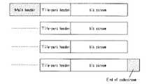
図6には、この符号列データの1フレーム分の概略構成を示している。この符号列データの先頭と各タイルの符号データ(bit stream)の先頭にはヘッダ(メインヘッダ(Main header)、タイル境界位置情報等であるタイルパートヘッダ(tile part header))と呼ばれるタグ情報が付加され、その後に、各タイルの符号化データが続く。なお、メインヘッダ(Main header)には、符号化パラメータや量子化パラメータが記述されている。そして、符号列データの終端には、再びタグ(end of codestream)が置かれる。また、図7は、符号化されたウェーブレット係数値が収容されたパケットをサブバンド毎に表わしたコードストリーム構造を示すものである。図7に示すように、タイルによる分割処理を行っても、あるいはタイルによる分割処理を行わなくても、同様のパケット列構造を持つことになる。
【0054】
一方、符号化データの復号化時には、画像データの符号化時とは逆に、各コンポーネント111の各タイル112の符号列データから画像データを生成する。この場合、タグ処理部105は、外部より入力した符号列データに付加されたタグ情報を解釈し、符号列データを各コンポーネント111の各タイル112の符号列データに分解し、その各コンポーネント111の各タイル112の符号列データ毎に復号化処理(伸長処理)を行う。このとき、符号列データ内のタグ情報に基づく順番で復号化の対象となるビットの位置が定められるとともに、量子化・逆量子化部103で、その対象ビット位置の周辺ビット(既に復号化を終えている)の並びからコンテキストが生成される。エントロピー符号化・復号化部104で、このコンテキストと符号列データから確率推定によって復号化を行い、対象ビットを生成し、それを対象ビットの位置に書き込む。このようにして復号化されたデータは周波数帯域毎に空間分割されているため、これを2次元ウェーブレット変換・逆変換部102で2次元ウェーブレット逆変換を行うことにより、画像データの各コンポーネントの各タイルが復元される。復元されたデータは色空間変換・逆変換部101によって元の表色系の画像データに変換される。
【0055】
以上が、「JPEG2000アルゴリズム」の概要である。
【0056】
以下、本発明の実施の一形態について説明する。なお、ここでは、JPEG2000を代表とする画像圧縮伸長技術に関する例について説明するが、言うまでもなく、本発明は以下の説明の内容に限定されるものではない。
【0057】
本実施の形態のサーバコンピュータ及びクライアントコンピュータは、そのコンピュータにインストールされるか、あるいは解釈されて実行される画像処理プログラムによって動作制御されて各種の画像処理を実行する。本実施の形態では、そのような画像処理プログラムを記憶する記憶媒体も紹介する。
【0058】
図8は、本実施の形態におけるシステム構築例を示す模式図である。
【0059】
本実施の形態の画像データ処理システムでは、画像処理装置であるサーバコンピュータ2にLAN(Local Area Network)等のネットワーク3を介してクライアントコンピュータ4が複数台接続されたサーバクライアントシステム1を想定する。このサーバクライアントシステム1は、スキャナやデジタルカメラ等の画像入力装置5及びプリンタ等の画像出力装置6をネットワーク3上でシェアし得る環境が整えられている。また、ネットワーク3上には、マルチファンクションペリフェラルと称されるMFP7が接続され、このMFP7が画像入力装置5や画像出力装置6として機能するように環境が構築されていても良い。
【0060】
このようなサーバクライアントシステム1は、例えばイントラネット8を介して別のサーバクライアントシステム1とのデータ通信可能に構築され、インターネット通信網9を介して外部環境とデータ通信可能に構築されている。
【0061】
サーバコンピュータ2は、文書管理サーバ2aとデータ変換サーバ2bとで構成されている。文書管理サーバ2aは、各種文書の画像イメージを画像データとして記憶する文書管理機能を発揮するものである。データ変換サーバ2bは、例えば画像データからテキストデータを抽出するOCR(Optical Character Reader)処理等の各種のデータ変換機能を発揮するものである。
【0062】
以下においては、本発明の特長的な機能を発揮する画像処理装置であるサーバコンピュータ2(特に、データ変換サーバ2b)について説明する。
【0063】
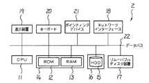
図9は、本実施の形態における画像処理装置としてのサーバコンピュータ2のモジュール構成図である。サーバコンピュータ2は、情報処理を行うCPU(Central Processing Unit)11、情報を格納するROM(Read Only Memory)12及びRAM(Random Access Memory)13等の一次記憶装置14、後述する圧縮符号を記憶する記憶部であるHDD(Hard Disk Drive)15等の二次記憶装置16、情報を保管したり外部に情報を配布したり外部から情報を入手するためのCD−ROMドライブ等のリムーバブルディスク装置17、ネットワーク3を介して画像入力装置5や外部の他のコンピュータと通信により情報を伝達するためのネットワークインターフェース18、処理経過や結果等を操作者に表示するCRT(Cathode Ray Tube)やLCD(Liquid Crystal Display)等の表示装置19、並びに操作者がCPU11に命令や情報等を入力するためのキーボード20、マウス等のポインティングディバイス21等から構成されており、これらの各部間で送受信されるデータをバスコントローラ22が調停して動作する。
【0064】
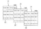
本実施の形態においては、サーバコンピュータ2のHDD15に圧縮符号化された画像データが記憶保持される。なお、サーバコンピュータ2のHDD15に記憶保持されている画像データは、「JPEG2000アルゴリズム」に従って生成された圧縮符号である。より具体的には、圧縮符号は、図10に示すような矩形領域(タイル)に分割された分割画像を圧縮符号化して一次元に並べることにより、図11に示すような構成になる。図11において、SOCは、コードストリームの開始を示すマーカセグメントである。また、MHは、メインヘッダであり、コードストリーム全体に共通する値を格納している。コードストリーム全体に共通する値としては、例えばタイル横量、タイル縦量、画像横量、画像縦量などが記録されている。MHに続くデータは、各タイルを符号化したデータであり、図11では図10に示すタイルの番号に従って主走査方向/副走査方向に各タイルを圧縮したデータが並べられている。圧縮符号の最後にあるEOCマーカは、圧縮符号の最後であることを示すマーカセグメントである。
【0065】
また、図12は「JPEG2000アルゴリズム」に従って生成された圧縮符号の解像度モデルを示す説明図である。図12に示すように、「JPEG2000アルゴリズム」に従って生成された圧縮符号においては、一つの画像ファイル内で低解像度データと高解像度データとに分けることが可能になっている。なお、図12では2種類の解像度だけを示しているが、実際には、全てのデータを1とすると、DWTにおけるオクターブ分割に対応した任意の階層(デコンポジション・レベル)に応じて、1/2,1/4,1/8,1/16,・・・,1/2nと複数の低解像度部分に係る圧縮符号を抽出することが可能である。
【0066】
このようなサーバコンピュータ2では、ユーザが電源を投入するとCPU11がROM12内のローダーというプログラムを起動させ、HDD15よりオペレーティングシステムというコンピュータのハードウェアとソフトウェアとを管理するプログラムをRAM13に読み込み、このオペレーティングシステムを起動させる。このようなオペレーティングシステムは、ユーザの操作に応じてプログラムを起動したり、情報を読み込んだり、保存を行ったりする。オペレーティングシステムのうち代表的なものとしては、Windows(登録商標)、UNIX(登録商標)等が知られている。これらのオペレーティングシステム上で走る動作プログラムをアプリケーションプログラムと呼んでいる。
【0067】
ここで、サーバコンピュータ2は、アプリケーションプログラムとして、画像処理プログラムをHDD15に記憶している。この意味で、HDD15は、画像処理プログラムを記憶する記憶媒体として機能する。
【0068】
また、一般的には、サーバコンピュータ2のHDD15等の二次記憶装置16にインストールされる動作プログラムは、CD−ROMやDVD−ROM等の光情報記録メディアやFD等の磁気メディア等に記録され、この記録された動作プログラムがHDD15等の二次記憶装置16にインストールされる。このため、CD−ROM等の光情報記録メディアやFD等の磁気メディア等の可搬性を有する記憶媒体も、画像処理プログラムを記憶する記憶媒体となり得る。さらには、画像処理プログラムは、例えばネットワークインターフェース18を介して外部から取り込まれ、HDD15等の二次記憶装置16にインストールされても良い。
【0069】
サーバコンピュータ2は、オペレーティングシステム上で動作する画像処理プログラムが起動すると、この画像処理プログラムに従い、CPU11が各種の演算処理を実行して各部を集中的に制御する。サーバコンピュータ2のCPU11が実行する各種の演算処理のうち、本実施の形態の特長的な処理について以下に説明する。
【0070】
ここで、サーバコンピュータ2のCPU11が実行する各種の演算処理により実現される機能について説明する。図13に示すように、画像処理装置であるサーバコンピュータ2のデータ変換サーバ2bにおいては、本実施の形態の特徴的な機能を発揮する解像度選択手段である解像度選択部31、及び各種の画像処理機能を行う画像処理手段である領域識別部32、2値化部33、文字認識部34、タイトル抽出部35が、CPU11が実行する各種の演算処理により実現されている。なお、リアルタイム性が重要視される場合には、処理を高速化する必要がある。そのためには、論理回路(図示せず)を別途設け、論理回路の動作により各種機能を実現するようにするのが望ましい。
【0071】
領域識別部32、2値化部33、文字認識部34、タイトル抽出部35については、周知の画像処理を実行するものであるため、簡単に説明する。
【0072】
領域識別部32は、領域識別手段として機能するものであって、圧縮符号を復号した画像中から文字領域と文字領域以外の領域(写真や図など)とを識別する。2値化部33は、領域識別部32により識別された文字領域の画像を2値画像として切り出す。そして、このようにして切り出された2値画像は、文字認識部34に送られる。文字認識部34は、文字認識手段として機能するものであって、いわゆるOCR(Optical Character Reader)処理を実行するものである。文字認識部34は、切り出された2値画像を、文字画像と文字コードとの組みを予め記憶した辞書ファイルと比較(パターンマッチング)し、相違度の小さい文字画像又は類似度の大きな文字画像に組み合わされた文字コードをOCR処理結果として出力する。
【0073】
また、タイトル抽出部35は、タイトル抽出手段として機能するものであって、圧縮符号を復号した画像中からタイトル領域を抽出するとともに、当該タイトル領域の文字を認識して抽出する。タイトル領域の文字認識は、文字認識部34と同様に、いわゆるOCR(Optical Character Reader)処理により実行される。
【0074】
以上のような各部の処理を経ることで、画像データからレイアウト情報等も再現したHTML形式ファイルやワープロ形式ファイルが生成される。また、このファイルには、タイトル抽出部35より抽出されたタイトルが付けられている。
【0075】
ところで、文字認識部34においては、400dpi程度の高い解像度の画像が必要とされる。また、領域識別部32においては、100dpi程度の低い解像度の画像でも処理が可能とされている。ただし、領域識別処理の中において、表抽出処理や傾き角度検出処理を行う場合には罫線情報を用いることから、比較的高い解像度の画像が必要となる。さらに、タイトル抽出部35においては、タイトル文字のような大きな文字を抽出することから、200dpi程度の低い解像度の画像でも処理が可能とされている。
【0076】
そこで、本実施の形態においては、各部(領域識別部32、2値化部33、文字認識部34、タイトル抽出部35)における処理に用いるのに最適な解像度を予め規定しておき、解像度選択部31によって、この最適な解像度の画像を選択するようにしたものである。具体的には、解像度選択部31は、直交変換にDWTを使ったJPEG2000アルゴリズムによって圧縮符号化された圧縮符号から、各部(領域識別部32、2値化部33、文字認識部34、タイトル抽出部35)における処理に用いるのに適した解像度の圧縮符号を選択する。「JPEG2000アルゴリズム」によれば、図3や図7等で前述したように、解像度に関してサブバンド階層構造を有することになる。そこで、本実施の形態の解像度選択部31においては、「JPEG2000アルゴリズム」の離散ウェーブレット変換処理によるサブバンド構造を利用し、各部(領域識別部32、2値化部33、文字認識部34、タイトル抽出部35)における処理に用いるのに適した解像度の圧縮符号を選択することが可能になっている。
【0077】
したがって、本実施の形態においては、解像度選択部31は、領域識別部32に対しては100dpiの低解像度画像に係る圧縮符号を選択して提供し、2値化部33及び文字認識部34に対しては400dpiの高解像度画像に係る圧縮符号を選択して提供し、タイトル抽出部35に対しては200dpiの低解像度画像に係る圧縮符号を選択して提供する。
【0078】
ここに、画像処理を行う各種の画像処理手段に対し、各画像処理に用いるのに適した解像度に係る階層の圧縮符号を提供するようにしたことにより、各種の画像処理における画像処理品質を高品質に維持しつつ、各種画像処理の処理速度の高速化を図ることができる。
【0079】
なお、本実施の形態においては、CPU11が実行する各種の演算処理により実現される各種の画像処理機能を行う画像処理手段として、領域識別部32、2値化部33、文字認識部34、タイトル抽出部35を説明したが、これに限るものではない。例えば、傾き角度検出機能や表抽出機能等を実現するものにも適用することができる。
本実施の形態によれば、画像データを1又は複数に分割した矩形領域毎に画素値を離散ウェーブレット変換して階層的に圧縮符号化された圧縮符号を用い、各種の画像処理を行う画像処理装置において、画像処理を行う各種の画像処理手段に対し、各画像処理に応じて予め規定された解像度に係る階層の圧縮符号を選択して提供する解像度選択手段を備え、画像処理を行う各種の画像処理手段に対し、各画像処理に用いるのに適した解像度に係る階層の圧縮符号を提供するようにしたことにより、各種の画像処理における画像処理品質を高品質に維持しつつ、各種画像処理の処理速度の高速化を図ることができる。
本実施の形態によれば、請求項1記載の画像処理装置において、前記解像度選択手段は、前記画像処理手段の一つが文字認識処理を行う文字認識手段である場合には、高解像度に係る階層の圧縮符号を選択して前記文字認識手段に提供することにより、いわゆるOCR(Optical Character Reader)処理である文字認識処理においては、高い解像度の画像が必要とされることから、高解像度に係る階層の圧縮符号を選択することで、精度の高い文字認識処理結果を得ることができる。
本実施の形態において、前記解像度選択手段は、前記画像処理手段の一つが領域識別処理を行う領域識別手段である場合には、低解像度に係る階層の圧縮符号を選択して前記領域識別手段に提供することにより、画像中から文字領域と文字領域以外の領域とを識別する領域識別処理においては、高い解像度の画像が必要とされないことから、低解像度に係る階層の圧縮符号を選択することで、領域識別処理結果の精度を維持しつつ、高速な処理を可能にすることができる。
本実施の形態において、前記解像度選択手段は、前記画像処理手段の一つがタイトル抽出処理を行うタイトル抽出手段である場合には、低解像度に係る階層の圧縮符号を選択して前記タイトル抽出手段に提供することにより、画像中からそのタイトル文字を抽出するタイトル抽出処理においては、タイトル文字のような大きな文字を抽出するために高い解像度の画像が必要とされないことから、低解像度に係る階層の圧縮符号を選択することで、タイトル抽出処理結果の精度を維持しつつ、高速な処理を可能にすることができる。
【0080】
【発明の効果】
各種の画像処理における画像処理品質を高品質に維持しつつ、各種画像処理の処理速度の高速化を図ることができる。
【図面の簡単な説明】
【図1】本発明の前提となるJPEG2000方式の基本となる階層符号化アルゴリズムを実現するシステムの機能ブロック図である。
【図2】原画像の各コンポーネントの分割された矩形領域を示す説明図である。
【図3】デコンポジション・レベル数が3の場合の、各デコンポジション・レベルにおけるサブバンドを示す説明図である。
【図4】プレシンクトを示す説明図である。
【図5】ビットプレーンに順位付けする手順の一例を示す説明図である。
【図6】符号列データの1フレーム分の概略構成を示す説明図である。
【図7】符号化されたウェーブレット係数値が収容されたパケットをサブバンド毎に表わしたコードストリーム構造を示す説明図である。
【図8】本発明の実施の一形態のシステム構築例を示す模式図である。
【図9】画像処理装置としてのサーバコンピュータのモジュール構成図である。
【図10】二次元に分割された分割画像の一例を示す説明図である。
【図11】その分割画像に基づいて「JPEG2000アルゴリズム」に従って生成された圧縮符号を示す説明図である。
【図12】「JPEG2000アルゴリズム」に従って生成された圧縮符号の解像度モデルを示す説明図である。
【図13】画像処理プログラムに基づいてCPUが実行する処理により実現される機能を示す機能ブロック図である。
【符号の説明】
2 画像処理装置
15 記憶媒体
31 解像度選択手段
32 画像処理手段、領域識別手段
33 画像処理手段
34 画像処理手段、文字認識手段
35 画像処理手段、タイトル抽出手段[0001]
BACKGROUND OF THE INVENTION
The present invention relates to an image processing apparatus,Image processing method,The present invention relates to a program and a storage medium.
[0002]
[Prior art]
Due to advances in image input technology and output technology, the demand for higher definition of images has increased greatly in recent years. For example, taking a digital camera as an example of an image input device, the price of a high-performance charge coupled device (CCD) having a number of pixels of 3 million or more has progressed, and the spread price range has increased. It has come to be widely used in products. And it is said that this increasing trend in the number of pixels will continue for a while.
[0003]
On the other hand, for image output / display devices, for example, products in the hard copy field such as laser printers, ink jet printers, sublimation printers, and flats such as CRTs, LCDs (liquid crystal display devices), and PDPs (plasma display devices). The high definition and low price of products in the soft copy field of panel displays are remarkable.
[0004]
Due to the market launch of these high-performance, low-priced image input / output products, high-definition images have become popular, and it is expected that demand for high-definition images will increase in all situations. In fact, the development of technologies related to networks such as personal computers and the Internet is accelerating these trends. In particular, recently, mobile devices such as mobile phones and notebook personal computers have become very popular, and opportunities for transmitting or receiving high-definition images from any point using communication means are rapidly increasing.
[0005]
Against this background, it is inevitable that the demand for higher performance or higher functionality for image compression / decompression technology that facilitates the handling of high-definition images will become stronger in the future.
[0006]
Thus, in recent years, a new method called JPEG2000, which can restore high-quality images even at a high compression rate, is being standardized as one of image compression methods that satisfy these requirements. In JPEG2000, it is possible to perform compression / decompression processing in a small memory environment by dividing an image into rectangular regions (tiles). That is, each tile becomes a basic unit for executing the compression / decompression process, and the compression / decompression operation can be performed independently for each tile.
[0007]
In general, when a paper document (original) is stored electronically, the following processes are executed in order. First, a paper document (original) is read one by one using an image input device such as a scanner or a digital still camera. Next, the read image data is converted into a compression code such as JPEG or JPEG2000 using an image compression apparatus. Finally, the compressed compression code is stored and saved in the storage device.
[0008]
By the way, image processing such as OCR (Optical Character Reader) processing for performing character recognition processing may be performed on the compressed code stored and stored in the storage device by such a procedure. In such image processing, there is one in which the resolution of an image subjected to processing is designated in advance in order to maintain high image processing quality. For example,
[0009]
[Patent Document 1]
JP2002-24766
[0010]
[Problems to be solved by the invention]
However, in the case of generating an HTML format file or a word processor format file in which layout information and the like are reproduced from image data, not only character recognition processing but also an area for identifying a character area and an area other than a character area from an image Various image processing such as identification processing and title extraction processing for assigning a title to a file is required. Therefore, when a high-resolution image suitable for character recognition processing is used, a high-accuracy character recognition processing result can be obtained in character recognition processing, but high resolution in region identification processing and title extraction processing. Since an image is not required, there arises a problem that wasteful processing occurs and processing speed decreases. In addition, when a low-resolution image suitable for region identification processing or title extraction processing is used, the processing speed can be increased, but there is a problem that character recognition accuracy is reduced in character recognition processing. It will occur.
[0011]
An object of the present invention is to provide an image processing apparatus capable of increasing the processing speed of various image processing while maintaining high image processing quality in various image processing,Image processing method,To provide a program and a storage medium.
[0012]
[Means for Solving the Problems]
The image processing apparatus of the present inventionFor each rectangular area obtained by dividing the image data into one or a plurality of pixels, pixel values are subjected to discrete wavelet transform, and compression codes hierarchically encoded are used.Image processingImage processing deviceBecause,Image processingCorresponding to eachFor image processing meansFor each image processing meansResolution selection means for selecting and providing a compression code of a hierarchy related to a prescribed resolutionThe prescribed resolution is higher in the order corresponding to the character recognition means for performing character recognition processing, the title extraction means for performing title extraction processing, and the area identification means for performing region identification processing..
[0013]
Accordingly, by providing a compression code of a hierarchy relating to a resolution suitable for use in each image processing to various image processing means for performing image processing, the image processing quality in various image processing is maintained at a high quality. However, it is possible to increase the processing speed of various image processing.
[0014]
The image processing method of the present invention is an image processing method for performing image processing using a compression code that is hierarchically compression-coded by performing discrete wavelet transform on pixel values for each rectangular area obtained by dividing image data into one or a plurality of rectangular areas. And a resolution selection step of selecting and providing a compression code of a hierarchy related to the resolution defined for each of the image processing means to a plurality of image processing means for performing image processing, wherein the specified resolution is , Character recognition means for performing character recognition processing, title extraction means for performing title extraction processing, and region identification means for performing region identification processing, in descending order..
[0015]
The program of the present invention is a program for causing a computer to execute the image processing method of the present invention..
[0016]
The storage medium of the present invention is a computer-readable storage medium storing the program of the present invention..
[0036]
DETAILED DESCRIPTION OF THE INVENTION
An embodiment of the present invention will be described with reference to FIGS.
[0037]
First, an outline of the “hierarchical encoding algorithm” and the “JPEG2000 algorithm” which are the premise of the present invention will be described.
[0038]
FIG. 1 is a functional block diagram of a system that implements a hierarchical encoding algorithm that is the basis of the JPEG2000 system. This system includes color space transform /
[0039]
One of the biggest differences between this system and the conventional JPEG algorithm is the conversion method. In JPEG, discrete cosine transform (DCT) is used. In this hierarchical coding algorithm, the two-dimensional wavelet transform /
[0040]
Another major difference is that in this hierarchical encoding algorithm, a functional block of the
[0041]
In many cases, color space conversion /
[0042]
Next, the JPEG2000 algorithm will be described.
[0043]
As shown in FIG. 2, in a color image, each component 111 (RGB primary color system here) of an original image is generally divided by a rectangular area. This divided rectangular area is generally called a block or a tile. In JPEG2000, it is generally called a tile. Therefore, such a divided rectangular area is hereinafter referred to as a tile. (In the example of FIG. 2, each component 111 is divided into a total of 16
[0044]
At the time of encoding image data, the data of each
[0045]
FIG. 3 shows subbands at each decomposition level when the number of decomposition levels is three. In other words, the tile original image (0LL) (decomposition level 0) obtained by tile division of the original image is subjected to two-dimensional wavelet transform, and the subbands (1LL, 1HL, 1LH shown in the decomposition level 1) , 1HH). Subsequently, the low-frequency component 1LL in this hierarchy is subjected to two-dimensional wavelet transformation to separate the subbands (2LL, 2HL, 2LH, 2HH) indicated by the
[0046]
Next, the bits to be encoded are determined in the specified encoding order, and the context is generated from the bits around the target bits by the quantization /
[0047]
The wavelet coefficients that have undergone the quantization process are divided into non-overlapping rectangles called “precincts” for each subband. This was introduced to use memory efficiently in implementation. As shown in FIG. 4, one precinct consists of three rectangular regions that are spatially coincident. Further, each precinct is divided into non-overlapping rectangular “code blocks”. This is the basic unit for entropy coding.
[0048]
The coefficient values after wavelet transform can be quantized and encoded as they are, but in JPEG2000, in order to increase the encoding efficiency, the coefficient values are decomposed into “bit plane” units, and each pixel or code block is divided. Ranking can be performed on “bitplanes”.
[0049]
Here, FIG. 5 is an explanatory diagram showing an example of a procedure for ranking the bit planes. As shown in FIG. 5, this example is a case where the original image (32 × 32 pixels) is divided into four 16 × 16 pixel tiles, and the size of the precinct and code block at the
[0050]
An explanatory diagram showing an example of the concept of a typical “layer” configuration for
[0051]
The layer structure is easy to understand when the wavelet coefficient values are viewed from the horizontal direction (bit plane direction). One layer is composed of an arbitrary number of bit planes. In this example, layers 0, 1, 2, and 3 are made up of bit planes of 1, 3, 1, and 3, respectively. A layer including a bit plane close to LSB (Least Significant Bit) is subject to quantization first. Conversely, a layer close to MSB (Most Significant Bit) is quantized to the end. It will remain without being. A method of discarding from a layer close to the LSB is called truncation, and the quantization rate can be finely controlled.
[0052]
The entropy encoding /
[0053]
FIG. 6 shows a schematic configuration for one frame of the code string data. Tag information called a header (main header, tile part header which is tile boundary position information, etc.) is provided at the head of the code string data and the head of the code data (bit stream) of each tile. Appended, followed by the encoded data for each tile. In the main header, coding parameters and quantization parameters are described. A tag (end of codestream) is placed again at the end of the code string data. FIG. 7 shows a code stream structure in which packets containing encoded wavelet coefficient values are represented for each subband. As shown in FIG. 7, the same packet string structure is obtained regardless of whether the tile division process is performed or the tile division process is not performed.
[0054]
On the other hand, when the encoded data is decoded, the image data is generated from the code string data of each
[0055]
The above is the outline of the “JPEG2000 algorithm”.
[0056]
Hereinafter, an embodiment of the present invention will be described. Although an example relating to an image compression / decompression technique represented by JPEG2000 will be described here, it goes without saying that the present invention is not limited to the contents of the following description.
[0057]
The server computer and the client computer according to the present embodiment execute various types of image processing by being controlled by an image processing program that is installed in the computer or interpreted and executed. In this embodiment, a storage medium for storing such an image processing program is also introduced.
[0058]
FIG. 8 is a schematic diagram showing an example of system construction in the present embodiment.
[0059]
The image data processing system according to the present embodiment assumes a
[0060]
Such a
[0061]
The
[0062]
Hereinafter, the server computer 2 (particularly, the data conversion server 2b) that is an image processing apparatus that exhibits the characteristic functions of the present invention will be described.
[0063]
FIG. 9 is a module configuration diagram of the
[0064]
In the present embodiment, image data that has been compression-encoded is stored and held in the
[0065]
FIG. 12 is an explanatory diagram showing a resolution model of a compression code generated according to the “JPEG2000 algorithm”. As shown in FIG. 12, a compression code generated according to the “JPEG2000 algorithm” can be divided into low resolution data and high resolution data within one image file. Although only two types of resolution are shown in FIG. 12, in reality, if all data are set to 1, according to an arbitrary hierarchy (decomposition level) corresponding to octave division in DWT, 1 / 2, 1/4, 1/8, 1/16, ..., 1/2nIt is possible to extract compression codes related to a plurality of low resolution portions.
[0066]
In such a
[0067]
Here, the
[0068]
In general, an operation program installed in the
[0069]
In the
[0070]
Here, functions realized by various arithmetic processes executed by the
[0071]
The
[0072]
The
[0073]
The title extraction unit 35 functions as a title extraction unit, extracts a title area from an image obtained by decoding a compression code, and recognizes and extracts characters in the title area. Character recognition in the title area is performed by so-called OCR (Optical Character Reader) processing, as with the
[0074]
Through the processing of each unit as described above, an HTML format file or a word processor format file in which layout information and the like are reproduced from the image data is generated. Further, the title extracted by the title extraction unit 35 is attached to this file.
[0075]
Incidentally, the
[0076]
Therefore, in the present embodiment, an optimal resolution to be used for processing in each unit (
[0077]
Therefore, in the present embodiment, the
[0078]
Here, by providing a compression code of a hierarchy relating to a resolution suitable for use in each image processing to various image processing means for performing image processing, image processing quality in various image processing is improved. The processing speed of various image processing can be increased while maintaining the quality.
[0079]
In the present embodiment, as image processing means for performing various image processing functions realized by various arithmetic processes executed by the
According to the present embodiment, image processing for performing various types of image processing using a compression code that is hierarchically compression-coded by discrete wavelet transform of pixel values for each rectangular area obtained by dividing image data into one or a plurality of rectangular areas The apparatus includes a resolution selection unit that selects and provides a compression code of a hierarchy related to a predetermined resolution according to each image processing for various image processing units that perform image processing, and performs various types of image processing. By providing the image processing means with the compression code of the hierarchy related to the resolution suitable for use in each image processing, various image processing can be performed while maintaining high image processing quality in various image processing. The processing speed can be increased.
According to the present embodiment, in the image processing apparatus according to
In the present embodiment, when one of the image processing units is a region identification unit that performs a region identification process, the resolution selection unit selects a compression code of a hierarchy related to a low resolution, and sends it to the region identification unit. By providing the area identification process for identifying the character area and the area other than the character area from the image, a high resolution image is not required. It is possible to perform high-speed processing while maintaining the accuracy of the region identification processing result.
In the present embodiment, when one of the image processing means is a title extraction means for performing a title extraction process, the resolution selection means selects a compression code of a hierarchy related to a low resolution and sends it to the title extraction means. By providing the title extraction process that extracts the title character from the image, a high-resolution image is not required to extract a large character such as the title character. By selecting a code, it is possible to perform high-speed processing while maintaining the accuracy of the title extraction processing result..
[0080]
【The invention's effect】
While maintaining high image processing quality in various image processing, it is possible to increase the processing speed of various image processing.
[Brief description of the drawings]
FIG. 1 is a functional block diagram of a system that realizes a hierarchical encoding algorithm that is the basis of the JPEG2000 system that is a premise of the present invention.
FIG. 2 is an explanatory diagram showing a divided rectangular area of each component of the original image.
FIG. 3 is an explanatory diagram showing subbands at each decomposition level when the number of decomposition levels is 3. FIG.
FIG. 4 is an explanatory diagram showing a precinct.
FIG. 5 is an explanatory diagram showing an example of a procedure for ranking bit planes;
FIG. 6 is an explanatory diagram illustrating a schematic configuration of one frame of code string data.
FIG. 7 is an explanatory diagram showing a code stream structure in which a packet containing an encoded wavelet coefficient value is represented for each subband.
FIG. 8 is a schematic diagram showing a system construction example according to an embodiment of the present invention.
FIG. 9 is a module configuration diagram of a server computer as an image processing apparatus.
FIG. 10 is an explanatory diagram illustrating an example of a divided image divided two-dimensionally.
FIG. 11 is an explanatory diagram showing a compression code generated according to the “JPEG2000 algorithm” based on the divided image.
FIG. 12 is an explanatory diagram showing a resolution model of a compression code generated according to the “JPEG2000 algorithm”.
FIG. 13 is a functional block diagram illustrating functions realized by processing executed by a CPU based on an image processing program.
[Explanation of symbols]
2 Image processing device
15 storage media
31 Resolution selection means
32 Image processing means, area identification means
33 Image processing means
34 Image processing means, character recognition means
35 Image processing means, title extraction means
Claims (6)
Translated fromJapanese画像処理毎に対応する画像処理手段に対し、前記画像処理手段毎に規定された解像度に係る階層の圧縮符号を選択して提供する解像度選択手段を有し、
前記規定された解像度は、文字認識処理を行う文字認識手段、タイトル抽出処理を行うタイトル抽出手段、及び、領域識別処理を行う領域識別手段に対応する順に高い画像処理装置。Using hierarchical compression coded compressed code by discrete wavelet transform pixel value image data for each rectangular region is divided into one or more,an image processing apparatus that performsimage processing,
A resolution selection unitthat selects and provides a compression code of a layer related to the resolution defined foreach image processing unit, with respectto the image processing unitcorresponding to each image processing;
The prescribed resolution is an image processing devicehaving a higher resolutionin the order corresponding to a character recognition unit that performs character recognition processing, a title extraction unit that performs title extraction processing, and a region identification unit that performs region identification processing.
前記解像度選択手段は、前記オクターブ分割による階層に対応する、前記画像データの2のべき乗分の1毎の解像度に対応するパケットを、選択する請求項1記載の画像処理装置。The compression code is compression encoded for each layer corresponding to the octave division that repeats the discrete wavelet transform recursively for the low frequency component in the vertical direction among the transform coefficients generated by the discrete wavelet transform, The hierarchy is a compression code composed of a plurality of packets corresponding to each hierarchy,
The image processing apparatus accordingto claim 1, wherein the resolution selecting unit selects a packet corresponding to a resolution of every power of 2 of the image data corresponding to the hierarchy by the octave division .
画像処理を行う複数の画像処理手段に対し、前記画像処理手段毎に規定された解像度に係る階層の圧縮符号を選択して提供する解像度選択ステップを有し、
前記規定された解像度は、文字認識処理を行う文字認識手段、タイトル抽出処理を行うタイトル抽出手段、及び、領域識別処理を行う領域識別手段に対応する順に高い画像処理方法。An image processing method for performing image processing using a compression code hierarchically compression-coded by discrete wavelet transform of pixel values for each rectangular region obtained by dividing image data into one or a plurality of regions,
A resolution selection step of selecting and providing a compression code of a hierarchy relating to the resolution defined for each of the image processing means for a plurality of image processing means for performing image processing;
The defined resolution is an image processing method in which the character recognition means for performing character recognition processing, the title extraction means for performing title extraction processing, and the region identification means for performing region identification processing are in descending order .
Priority Applications (1)
| Application Number | Priority Date | Filing Date | Title |
|---|---|---|---|
| JP2003016324AJP4052952B2 (en) | 2003-01-24 | 2003-01-24 | Image processing apparatus, image processing method, program, and storage medium |
Applications Claiming Priority (1)
| Application Number | Priority Date | Filing Date | Title |
|---|---|---|---|
| JP2003016324AJP4052952B2 (en) | 2003-01-24 | 2003-01-24 | Image processing apparatus, image processing method, program, and storage medium |
Publications (2)
| Publication Number | Publication Date |
|---|---|
| JP2004229095A JP2004229095A (en) | 2004-08-12 |
| JP4052952B2true JP4052952B2 (en) | 2008-02-27 |
Family
ID=32903815
Family Applications (1)
| Application Number | Title | Priority Date | Filing Date |
|---|---|---|---|
| JP2003016324AExpired - Fee RelatedJP4052952B2 (en) | 2003-01-24 | 2003-01-24 | Image processing apparatus, image processing method, program, and storage medium |
Country Status (1)
| Country | Link |
|---|---|
| JP (1) | JP4052952B2 (en) |
Families Citing this family (2)
| Publication number | Priority date | Publication date | Assignee | Title |
|---|---|---|---|---|
| JP5137759B2 (en) | 2008-09-18 | 2013-02-06 | キヤノン株式会社 | Image processing device |
| CN116110056B (en)* | 2022-12-29 | 2023-09-26 | 北京百度网讯科技有限公司 | Information extraction method and device, electronic equipment and storage medium |
- 2003
- 2003-01-24JPJP2003016324Apatent/JP4052952B2/ennot_activeExpired - Fee Related
Also Published As
| Publication number | Publication date |
|---|---|
| JP2004229095A (en) | 2004-08-12 |
Similar Documents
| Publication | Publication Date | Title |
|---|---|---|
| JP4064196B2 (en) | Client computer, server computer, program, storage medium, image data processing system, and image data processing method | |
| JP4111926B2 (en) | Image processing apparatus, program, storage medium, and image transmission method | |
| JP4111268B2 (en) | Thumbnail image display method, server computer, client computer, and program | |
| JP4128438B2 (en) | Image processing apparatus, program, storage medium, and image editing method | |
| JP4093405B2 (en) | Image processing apparatus, program, and storage medium | |
| US7526134B2 (en) | Image processing apparatus, program, recording medium, and data decompression method | |
| US7627185B2 (en) | Hierarchically compressing and coding and storing image data | |
| US7526133B2 (en) | Image processing apparatus, image processing program, and storage medium | |
| US20030068089A1 (en) | Image processing system processing code data | |
| US20040161156A1 (en) | Image processing apparatus, method, program and medium storing image processing program | |
| JP4723543B2 (en) | Image processing apparatus, image processing method, program, and storage medium | |
| JP4052952B2 (en) | Image processing apparatus, image processing method, program, and storage medium | |
| JP4280508B2 (en) | Misalignment correction apparatus, image processing apparatus, program, storage medium, and misalignment correction method | |
| JP4014085B2 (en) | Image processing apparatus, program, and storage medium | |
| JP4489474B2 (en) | Image processing apparatus, program, and recording medium | |
| JP4323178B2 (en) | Search object restriction device, image processing apparatus, program, storage medium, and search object restriction method | |
| JP3961966B2 (en) | Unnecessary part removing apparatus, image processing apparatus, program, storage medium, and unnecessary part removing method | |
| JP4093870B2 (en) | Image processing apparatus, program, and storage medium | |
| JP2004056648A (en) | Image processing apparatus, document management system, program, and storage medium | |
| JP4374063B2 (en) | Image processing apparatus, program, and storage medium | |
| JP4010957B2 (en) | Image processing apparatus, program, storage medium, and image forming apparatus |
Legal Events
| Date | Code | Title | Description |
|---|---|---|---|
| RD04 | Notification of resignation of power of attorney | Free format text:JAPANESE INTERMEDIATE CODE: A7424 Effective date:20041008 | |
| A621 | Written request for application examination | Free format text:JAPANESE INTERMEDIATE CODE: A621 Effective date:20051116 | |
| RD01 | Notification of change of attorney | Free format text:JAPANESE INTERMEDIATE CODE: A7421 Effective date:20051021 | |
| RD01 | Notification of change of attorney | Free format text:JAPANESE INTERMEDIATE CODE: A7421 Effective date:20060905 | |
| A977 | Report on retrieval | Free format text:JAPANESE INTERMEDIATE CODE: A971007 Effective date:20070803 | |
| A131 | Notification of reasons for refusal | Free format text:JAPANESE INTERMEDIATE CODE: A131 Effective date:20070807 | |
| A521 | Request for written amendment filed | Free format text:JAPANESE INTERMEDIATE CODE: A523 Effective date:20071009 | |
| TRDD | Decision of grant or rejection written | ||
| A01 | Written decision to grant a patent or to grant a registration (utility model) | Free format text:JAPANESE INTERMEDIATE CODE: A01 Effective date:20071106 | |
| A61 | First payment of annual fees (during grant procedure) | Free format text:JAPANESE INTERMEDIATE CODE: A61 Effective date:20071204 | |
| FPAY | Renewal fee payment (event date is renewal date of database) | Free format text:PAYMENT UNTIL: 20101214 Year of fee payment:3 | |
| R150 | Certificate of patent or registration of utility model | Free format text:JAPANESE INTERMEDIATE CODE: R150 | |
| FPAY | Renewal fee payment (event date is renewal date of database) | Free format text:PAYMENT UNTIL: 20101214 Year of fee payment:3 | |
| FPAY | Renewal fee payment (event date is renewal date of database) | Free format text:PAYMENT UNTIL: 20111214 Year of fee payment:4 | |
| FPAY | Renewal fee payment (event date is renewal date of database) | Free format text:PAYMENT UNTIL: 20111214 Year of fee payment:4 | |
| FPAY | Renewal fee payment (event date is renewal date of database) | Free format text:PAYMENT UNTIL: 20121214 Year of fee payment:5 | |
| FPAY | Renewal fee payment (event date is renewal date of database) | Free format text:PAYMENT UNTIL: 20131214 Year of fee payment:6 | |
| LAPS | Cancellation because of no payment of annual fees |