JP4051727B2 - Camera with display function - Google Patents
Camera with display functionDownload PDFInfo
- Publication number
- JP4051727B2 JP4051727B2JP19250197AJP19250197AJP4051727B2JP 4051727 B2JP4051727 B2JP 4051727B2JP 19250197 AJP19250197 AJP 19250197AJP 19250197 AJP19250197 AJP 19250197AJP 4051727 B2JP4051727 B2JP 4051727B2
- Authority
- JP
- Japan
- Prior art keywords
- display
- mode
- microprocessor
- time limit
- time
- Prior art date
- Legal status (The legal status is an assumption and is not a legal conclusion. Google has not performed a legal analysis and makes no representation as to the accuracy of the status listed.)
- Expired - Lifetime
Links
Images


Classifications
- G—PHYSICS
- G03—PHOTOGRAPHY; CINEMATOGRAPHY; ANALOGOUS TECHNIQUES USING WAVES OTHER THAN OPTICAL WAVES; ELECTROGRAPHY; HOLOGRAPHY
- G03B—APPARATUS OR ARRANGEMENTS FOR TAKING PHOTOGRAPHS OR FOR PROJECTING OR VIEWING THEM; APPARATUS OR ARRANGEMENTS EMPLOYING ANALOGOUS TECHNIQUES USING WAVES OTHER THAN OPTICAL WAVES; ACCESSORIES THEREFOR
- G03B7/00—Control of exposure by setting shutters, diaphragms or filters, separately or conjointly
- G03B7/26—Power supplies; Circuitry or arrangement to switch on the power source; Circuitry to check the power source voltage
- H—ELECTRICITY
- H04—ELECTRIC COMMUNICATION TECHNIQUE
- H04N—PICTORIAL COMMUNICATION, e.g. TELEVISION
- H04N23/00—Cameras or camera modules comprising electronic image sensors; Control thereof
- H04N23/60—Control of cameras or camera modules
- H04N23/65—Control of camera operation in relation to power supply
- H04N23/651—Control of camera operation in relation to power supply for reducing power consumption by affecting camera operations, e.g. sleep mode, hibernation mode or power off of selective parts of the camera
- H—ELECTRICITY
- H04—ELECTRIC COMMUNICATION TECHNIQUE
- H04N—PICTORIAL COMMUNICATION, e.g. TELEVISION
- H04N23/00—Cameras or camera modules comprising electronic image sensors; Control thereof
- H04N23/60—Control of cameras or camera modules
- H04N23/63—Control of cameras or camera modules by using electronic viewfinders
- H04N23/631—Graphical user interfaces [GUI] specially adapted for controlling image capture or setting capture parameters
- G—PHYSICS
- G09—EDUCATION; CRYPTOGRAPHY; DISPLAY; ADVERTISING; SEALS
- G09G—ARRANGEMENTS OR CIRCUITS FOR CONTROL OF INDICATING DEVICES USING STATIC MEANS TO PRESENT VARIABLE INFORMATION
- G09G2330/00—Aspects of power supply; Aspects of display protection and defect management
- G09G2330/02—Details of power systems and of start or stop of display operation
- G09G2330/021—Power management, e.g. power saving
- G09G2330/022—Power management, e.g. power saving in absence of operation, e.g. no data being entered during a predetermined time
- G—PHYSICS
- G09—EDUCATION; CRYPTOGRAPHY; DISPLAY; ADVERTISING; SEALS
- G09G—ARRANGEMENTS OR CIRCUITS FOR CONTROL OF INDICATING DEVICES USING STATIC MEANS TO PRESENT VARIABLE INFORMATION
- G09G3/00—Control arrangements or circuits, of interest only in connection with visual indicators other than cathode-ray tubes
- G09G3/20—Control arrangements or circuits, of interest only in connection with visual indicators other than cathode-ray tubes for presentation of an assembly of a number of characters, e.g. a page, by composing the assembly by combination of individual elements arranged in a matrix no fixed position being assigned to or needed to be assigned to the individual characters or partial characters
- G09G3/34—Control arrangements or circuits, of interest only in connection with visual indicators other than cathode-ray tubes for presentation of an assembly of a number of characters, e.g. a page, by composing the assembly by combination of individual elements arranged in a matrix no fixed position being assigned to or needed to be assigned to the individual characters or partial characters by control of light from an independent source
- G09G3/3406—Control of illumination source
Landscapes
- Engineering & Computer Science (AREA)
- Multimedia (AREA)
- Signal Processing (AREA)
- Human Computer Interaction (AREA)
- Physics & Mathematics (AREA)
- General Physics & Mathematics (AREA)
- Studio Devices (AREA)
- Indication In Cameras, And Counting Of Exposures (AREA)
Description
Translated fromJapanese【0001】
【発明の属する技術分野】
本発明は、画像データもしくは表示データ(文字情報など)の表示手段を有するカメラに関する。特に、動作モードなどの設定変更に応じて、表示手段の消灯時間を可変するカメラに関する。
【0002】
【従来の技術】
近年、撮像素子を用いて被写体像を光電変換し、光電変換された画像データを記録媒体などに記録する電子カメラが知られている。
この種の電子カメラには、ファインダの代用として被写体像をモニタ表示するための液晶パネルや、記録媒体上の画像データを再生表示するための液晶パネルなどを備えたものも多い。この液晶パネルの裏面側には、白色光源であるバックライトが配置される。
【0003】
一般に、このようなバックライトは消費電力が大きいため、内部電池の使用時間が顕著に短くなる。そこで、装置の無操作状態が継続した場合には、バックライトを消灯して、節電状態に入るものが知られている(特開平6−119090号公報)。
【0004】
【発明が解決しようとする課題】
一般に、カメラは種々の使用状況や使用場面ごとに、操作者の外部操作を行う頻度が大きく異なる。また、操作者が液晶パネルの表示を頻繁に必要とする局面と、液晶パネルの表示をさほど必要としない局面とが存在する。
【0005】
ところが、上述したような従来例では、バックライトを消灯して節電状態に入る時間(以下「表示制限時間」という)が、一律に設定される。
そのため、ある局面では、操作者がしばらく時間をおいて次の操作を行おうとした際に、既にバックライトが消灯しており、操作を円滑に続行できないという不具合があった。
【0006】
また、別の局面では、操作者が液晶パネルの表示を必要としていないにもかかわらず、バックライトの点灯を無駄に継続しているという不具合があった。
一方、操作者の地理的な条件などにより、電池のコストや入手のしやすさなどは大きく異なる。
そのため、ある地理的な条件においては、カメラの操作性をある程度犠牲にしても、電池の使用時間を長く確保したいという要望があった。
【0007】
また、別の地理的な条件においては、電池の使用時間を多少短縮しても、カメラの操作性を優先させたいという要望があった。
そこで、請求項1に記載の発明では、カメラの使用場面に応じて表示制限時間を自動的に変更する「表示機能を有するカメラ」を提供することを目的とする。
【0008】
【課題を解決するための手段】
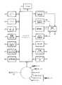
図1は、請求項1に記載の発明に対応する原理ブロック図である。以下、図1に対応付けて、上記課題の解決手段を説明する。
【0009】
請求項1に記載の発明は、カメラの動作モードとして、被写体の撮影および記録を行うための撮影モードと、撮影モードにおいて撮像もしくは記録された画像データを外部に転送するための通信モードとを有し、前記撮影モードおよび前記通信モードを含む複数の動作モードを外部操作に応じて切り換えるモード設定手段1と、モード設定手段1を介して設定された動作モードに対応して、カメラの動作を制御する動作制御手段2と、カメラの動作に応じて生成される画像データもしくは表示データを画面表示する表示手段3とを備えた表示機能を有するカメラにおいて、複数の動作モードに対して表示制限時間を割り当てることにより予め作成された、動作モードと表示制限時間との対応関係を記憶する記憶手段4と、記憶手段4に記憶された対応関係に基づいて、現時点の動作モードに割り当てられる表示制限時間を求める時間設定手段5と、無操作状態における表示手段3の表示継続時間を計測し、該表示継続時間が時間設定手段5において求めた表示制限時間を越えた場合に、表示手段3の表示輝度を低減もしくは消灯する節電手段6とを備え、記憶手段に記憶された対応関係では、撮影モードにおける表示制限時間は複数の時間の中から手動設定可能であり、通信モードにおける表示制限時間は撮影モードにおける表示制限時間よりも短い単一の時間であることを特徴とする。
【0010】
(作用)
請求項1にかかわるカメラは、撮影モードと、その他の動作モードとを有する。
記憶手段4には、これらの動作モードと予め定められた表示制限時間との対応関係が記録される。
時間設定手段5は、この記憶手段4の対応関係を参照して、現時点の動作モードに割り当てられた表示制限時間をもとめる。
【0011】
節電手段6は、無操作状態における表示手段3の表示継続時間を計測する。この節電手段6は、該表示継続時間が時間設定手段5において求めた表示制限時間を越えた場合に、表示手段3の表示輝度を低減もしくは消灯する。
このような作用により、操作者が、モード設定手段1を操作して動作モードを切り換えるたびに、表示制限時間の値が自動的に変化する。
【0012】
さらに、請求項1にかかわるカメラでは、撮影モードから通信モードへ設定変更を行うと、表示制限時間の設定が自動的に短縮される。
通常、通信モードでは、通信期間中、表示手段3の表示画像を注視する必要性がさほどない。
したがって、通信モードにおいて表示制限時間を短縮することにより、通信モードの操作性をさほど犠牲にすることなく、表示手段3の電力消費を効率的に抑えることができる。
【0013】
一方、撮影モードにおける表示制限時間は、通信モードの事情と独立して長めに設定することができる。したがって、撮影モードの表示制限時間は、通信モードのように極端に短く設定する必要がなく、撮影モード中に表示手段3がたびたび消灯するなどの不具合は生じない。
【0014】
【発明の実施の形態】
以下、図面に基づいて本発明における実施の形態を説明する。
(第1の実施形態)
図2は、第1の実施形態を示す概略ブロック図である。なお、第1の実施形態は、請求項1に記載の発明に対応する実施形態である。
【0015】
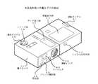
図3は、本実施形態の外観を示す斜視図である。
図2および図3において、電子カメラ31の前面には、撮影レンズ32が配置され、撮影レンズ32の光軸上には、撮像素子33が配置される。
撮像素子33の画像出力端子は、γ変換やAD変換などを行う画像処理回路(図示せず)を介してマイクロプロセッサ34に接続される。
【0016】
マイクロプロセッサ34の制御端子には、絞り駆動部35,フォーカスレンズ駆動部36およびズームレンズ駆動部37が接続される。これらの駆動部35〜37は、撮影レンズ32内部のレンズ群をそれぞれ前後に駆動する。
また、電子カメラ31の上面には、レリーズ釦39,選択ダイアル40および回転ダイアル41が配置される。これら操作部材39〜41の出力端子は、マイクロプロセッサ34にそれぞれ接続される。なお、回転ダイアル41は、公知の複合操作部材であり、正逆回転により2相エンコーダパルスが発生し、ダイアルの回転中心に向かう押圧操作により接点パルスが発生するものである。
【0017】
さらに、電子カメラ31の上面には、コマ番号や露出情報などを表示するデータ表示部42と、画像を表示する画像表示部43が配置される。これらの表示部42,43の制御入力端子は、マイクロプロセッサ34にそれぞれ接続される。
また、電子カメラ31の前面には、閃光部44,パッシブ測距部45,ファインダ46およびIrDA投受光部47がそれぞれ配置される。これらの閃光部44,パッシブ測距部45およびIrDA投受光部47は、マイクロプロセッサ34にそれぞれ接続される。
【0018】
その他、マイクロプロセッサ34には、設定情報などを記録する不揮発性のメモリ48と、画像情報を記録するメモリカード49と、表示継続時間の計測を行う計時回路50とが接続される。
なお、請求項1に記載の発明と第1の実施形態との対応関係については、モード設定手段1は選択ダイアル40に対応し、動作制御手段2はマイクロプロセッサ34の「動作モードに従って撮像素子33などを制御する機能」に対応し、表示手段3は画像表示部43に対応し、記憶手段4はマイクロプロセッサ34内部の記憶回路およびメモリ48に対応し、時間設定手段5はマイクロプロセッサ34の「現時点の動作モードに割り当てられた表示制限時間を求める機能」に対応し、節電手段6は計時回路50およびマイクロプロセッサ34の「表示継続時間が表示制限時間を越えると画像表示部43のバックライトを消灯する機能」に対応する。
【0019】
以下、各動作モードごとに電子カメラ31の動作を説明する。
(撮影モード)
図4は、撮影モードの動作を説明する流れ図である。
まず最初に、選択ダイアル40の操作により電子カメラ31に主電源が投入されると、マイクロプロセッサ34は、図4に示すステップS1から動作を開始する。
【0020】
すなわち、マイクロプロセッサ34は、計時回路50における表示継続時間の計測値Tdをリセットする(図4S1)。
次に、マイクロプロセッサ34は、選択ダイアル40から動作モードの設定を取り込む(図4S2)。ここでの動作モードは、次のような5種類の動作モードに分類される。
【0021】
(1)MODE1・・撮影モードの1つ。予め記憶されている「撮影条件の組み合わせ」をそのまま使用する。
(2)MODE2・・撮影モードの1つ。節電のために画像表示部43のバックライトを常時消灯する。撮影時のフレーミングは、光学式ファインダを専ら使用する。
(3)MODE3・・撮影モードの1つ。手動設定された撮影条件を使用する。
(4)再生モード・・メモリカード49に記録された画像データを読み出し、画像表示部43に表示するモード。
(5)通信モード・・IrDA投受光部47を利用して、外部機器に画像データを転送するモード。
【0022】
ここで、動作モードが撮影モード以外に設定されていた場合、マイクロプロセッサ34は、各対応する制御ステップに動作を移行する(図4S3)。すなわち、再生モードに設定されていた場合、マイクロプロセッサ34は、図7に示すステップS21に動作を移行する。また、通信モードに設定されていた場合、マイクロプロセッサ34は、図8に示すステップS31に動作を移行する。
【0023】
一方、撮影モードに設定されていた場合、マイクロプロセッサ34は、回転ダイアル41が1秒以上押されていたか否かを判定する(図4S4)。
ここで、回転ダイアル41が1秒以上押されていた場合、マイクロプロセッサ34は、撮影条件などの手動設定を行うためのメニュー処理を次のように実行する(図4S5)。
【0024】
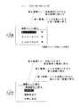
まず、マイクロプロセッサ34は、図5に示すような第1階層のメニューを画像表示部43に表示する。この状態で、操作者は回転ダイアル41を回転してメニュー項目の選択を変更し、回転ダイアル41を押してメニュー項目を選択する。
【0025】
このようなメニュー選択操作に従って、マイクロプロセッサ34は、図5および図6に示す下位階層のメニューを画像表示部43に順次表示する。マイクロプロセッサ34は、この階層的なメニュー選択の結果を取り込み、メモリ48内の設定情報に記録する。
【0026】
次に、マイクロプロセッサ34は、コマ番号などの表示データをデータ表示部42に表示する(図4S6)。
ここで、電子カメラ31が節電モード(上記のMODE2)に設定されていると(図4S7のYES側)、マイクロプロセッサ34は、後述するモニタ表示の処理を省いて、図4に示すステップS11に動作を移行する。
【0027】
一方、電子カメラ31が節電モード以外(上記のMODE1,3)に設定されていると(図4S7のNO側)、マイクロプロセッサ34は、パッシブ測距部45の測距値に基づいて、撮影レンズ32を合焦させる(図4S8)。
この状態で、マイクロプロセッサ34は、モニタ表示を行うために、撮像素子33を電子シャッタ動作させて、モニタ画像を取り込む(図4S9)。マイクロプロセッサ34は、このモニタ画像を画像表示部43に表示する(図4S10)。
【0028】
このような処理の後、マイクロプロセッサ34は、レリーズ釦39が全押しされているか否かを判定する(図4S11)。
ここで、レリーズ釦39が全押しされていない場合(図4S11のNO側)、マイクロプロセッサ34は、後述する撮影動作を省いて、ステップS2に動作を戻す。
【0029】
一方、レリーズ釦39が全押しされている場合(図4S11のYES側)、マイクロプロセッサ34は、撮影動作を次のように実行する。
まず、マイクロプロセッサ34は、パッシブ測距部45の測距値に基づいて、撮影レンズ32を合焦状態まで移動させる(図4S12)。
次に、マイクロプロセッサ34は、撮像素子33を電子シャッタ動作させて、画像データを取り込む(図4S13)。マイクロプロセッサ34は、このように取り込まれた画像データを画像圧縮した後、メモリカード49に記録する(図4S14)。
【0030】
このような撮影動作が完了した後、マイクロプロセッサ34は、ステップS2に動作を戻す。
以上説明した一連の制御ステップによって、撮影モードの動作が実行される。
次に、再生モードの動作を説明する。
(再生モード)
図7は、再生モードの動作を説明する流れ図である。
【0031】
図7において、マイクロプロセッサ34は、まず計時回路50における表示継続時間の計測値Tdをリセットする(図7S21)。
次に、マイクロプロセッサ34は、選択ダイアル40から動作モードの設定を取り込む(図7S22)。
ここで、動作モードが再生モード以外に設定されていた場合、マイクロプロセッサ34は、各対応する制御ステップに動作を移行する(図7S23)。すなわち、撮影モードに設定されていた場合、マイクロプロセッサ34は、図4に示すステップS1に動作を移行する。また、通信モードに設定されていた場合、マイクロプロセッサ34は、図8に示すステップS31に動作を移行する。
【0032】
一方、再生モードに設定されている場合、マイクロプロセッサ34は、回転ダイアル41の回転操作に応じて、データ表示部42に表示するコマ番号の値を増減させる(図7S24)。
次に、マイクロプロセッサ34は、回転ダイアル41が押されたか否かを判定する(図7S25)。
【0033】
ここで、回転ダイアル41が押されていない場合(図7S25のNO側)、マイクロプロセッサ34は、後述する再生動作を省いて、ステップS22に動作を戻す。
一方、回転ダイアル41が押された場合(図7S25のYES側)、マイクロプロセッサ34は、現在のコマ番号が示す画像データをメモリカード49から読み出し、画像伸長した後に画像表示部43に再生表示する(図7S26)。このような再生動作の後に、マイクロプロセッサ34は、ステップS22に動作を戻す。
【0034】
以上説明した一連の制御ステップによって、再生モードの動作が実行される。
次に、通信モードの動作を説明する。
(通信モード)
図8は、通信モードの動作を説明する流れ図である。
図8において、マイクロプロセッサ34は、まず計時回路50における表示継続時間の計測値Tdをリセットする(図8S31)。
【0035】
次に、マイクロプロセッサ34は、選択ダイアル40から動作モードの設定を取り込む(図8S32)。
ここで、動作モードが通信モード以外に設定されていた場合、マイクロプロセッサ34は、各対応する制御ステップに動作を移行する(図8S33)。すなわち、撮影モードに設定されていた場合、マイクロプロセッサ34は、図4に示すステップS1に動作を移行する。また、再生モードに設定されていた場合、マイクロプロセッサ34は、図7に示すステップS21に動作を移行する。
【0036】
一方、通信モードに設定されていた場合、マイクロプロセッサ34は、回転ダイアル41の回転操作に応じて、データ表示部42に表示するコマ番号の値を増減させる(図8S34)。
次に、マイクロプロセッサ34は、回転ダイアル41が押されたか否かを判定する(図8S35)。
【0037】
ここで、回転ダイアル41が押されていない場合(図8S35のNO側)、マイクロプロセッサ34は、後述する通信動作を省いて、ステップS32に動作を戻す。
一方、回転ダイアル41が押された場合(図8S35のYES側)、マイクロプロセッサ34は、現在のコマ番号が示す画像データをメモリカード49から読み出し、画像伸長した後に画像表示部43に再生表示する(図8S36)。
【0038】
この状態で、マイクロプロセッサ34は、メモリカード49から読み出した画像データを、IrDA投受光部47を介して外部機器に転送出力する(図8S37)。
このような通信動作の完了後に、マイクロプロセッサ34は、ステップS32に動作を戻す。
【0039】
以上説明した一連の制御ステップによって、通信モードの動作が実行される。
次に、バックライト消灯に関する処理を説明する。
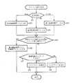
(バックライト消灯に関するタイマー割り込み処理)
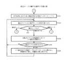
図9は、バックライト消灯に関するタイマー割り込み処理を説明する流れ図である。なお、このような割り込み処理は、マイクロプロセッサ34によって所定時間おき(例えば、1秒おき)に実行される。
【0040】
図9においてまず最初に、マイクロプロセッサ34は、メモリ48内に記憶された時間Tsを、表示制限時間Tにセットする。ここでの時間Tsは、図5に示したメニュー処理の中の「タイマーセット」において手動設定される時間値であり、デフォルト状態では「1分」に設定されている(図9S41)。
ここでの「1分」は、デフォルト状態において撮影モードに予め割り当てられる表示制限時間に該当する。
【0041】
次に、マイクロプロセッサ34は、選択ダイアル40の状態を取り込み、現時点の動作モードが、再生モードか否かを判定する(図9S42)。もしも、再生モードの場合、マイクロプロセッサ34は、表示制限時間Tを「3分」に変更する(図9S43)。
ここでの「3分」は、再生モードに対して予め割り当てられる表示制限時間に該当する。
【0042】
さらに、マイクロプロセッサ34は、選択ダイアル40の状態を取り込み、現時点の動作モードが、通信モードか否かを判定する(図9S44)。もしも、通信モードの場合、マイクロプロセッサ34は、表示制限時間Tを「20秒」に変更する(図9S45)。
ここでの「20秒」は、通信モードに対して予め割り当てられる表示制限時間に該当する。
【0043】
このような処理の後、マイクロプロセッサ34は、前回のタイマー割り込み以降、スイッチ等の外部操作に対する処理を行ったか否かを判断する(図9S46)。
もしも、スイッチ等が外部操作されていた場合(図9S46のYES側)、計時回路50における表示継続時間の計測値Tdをリセットして、割り込み処理を終了する(図9S47)。
【0044】
一方、スイッチ等が外部操作されていない場合(図9S46のNO側)、マイクロプロセッサ34は、表示継続時間Tdが表示制限時間Tを越えたか否かを判定する(図9S48)。
表示継続時間Tdが表示制限時間Tを越えていない場合(図9S48のNO側)、画像表示部43のバックライトを点灯させた状態で、割り込み処理を終了する(図9S49)。
【0045】
一方、表示継続時間Tdが表示制限時間Tを越えている場合(図9S48のYES側)、画像表示部43のバックライトを消灯して、割り込み処理を終了する(図9S50)。
このようなタイマー割り込み処理の実行により、各動作モードごとに割り当てられた表示制限時間Tを越えた時点で、画像表示部43のバックライトが消灯する。
【0046】
(第1の実施形態の効果など)
以上説明した動作により、第1の実施形態では、操作者が、選択ダイアル40を操作して動作モードを切り換えるたびに、表示制限時間の値が自動的に変化する。
特に、撮影モードから再生モードへ設定変更を行うと、表示制限時間の設定が自動的に延長される。したがって、再生画像の鑑賞中などにバックライトが勝手に消灯してしまうなどの不具合を極力解消することができる。
【0047】
また、撮影モードから通信モードへ設定変更を行うと、表示制限時間の設定が自動的に短縮される。したがって、通信中におけるバックライトの電力消費を極力抑えることができる。
次に、別の実施形態を説明する。
(第2の実施形態)
図10は、第2の実施形態におけるタイマー割り込み処理を示す流れ図である。
【0048】
なお、第2の実施形態における電子カメラの構成は、第1の実施形態の構成(図2および図3)と同様なので、ここでの重複説明を省略する。また、第2の実施形態における各動作モードの動作は、第1の実施形態の動作(図4,図7および図8)と同様なので、ここでの重複説明を省略する。
【0049】
以下、第2の実施形態における動作上の特徴点について説明する。
まず、図10に示すタイマー割り込み処理が開始すると、マイクロプロセッサ34は、メモリ48内に記憶された使用言語を取り込む。ここでの使用言語は、図5に示したメニュー処理の中の「LANGUAGE」において手動設定される使用言語であり、デフォルト状態では「英語」に設定されている。
【0050】
次に、マイクロプロセッサ34は、現時点の使用言語に割り当てられる表示制限時間を求めて、表示制限時間Tに設定する(図10S51)。
すなわち、使用言語が「日本語」の場合には、表示制限時間Tは「3分」に設定される(図10S52)。
また、使用言語が「英語」の場合には、表示制限時間Tは「20秒」に設定される(図10S53)。
【0051】
一方、使用言語が「その他の言語」の場合には、表示制限時間Tは「1分」に設定される(図10S54)。
このような処理の後、マイクロプロセッサ34は、前回のタイマー割り込み以降に、スイッチ等の外部操作に対する処理が行われたか否かを判断する(図10S55)。
【0052】
もしも、スイッチ等の外部操作がなされていた場合(図10S55のYES側)、計時回路50における表示継続時間の計測値Tdをリセットして、割り込み処理を終了する(図9S47)。
一方、スイッチ等が外部操作されていない場合(図10S55のNO側)、マイクロプロセッサ34は、表示継続時間Tdが表示制限時間Tを越えたか否かを判定する(図10S57)。
【0053】
表示継続時間Tdが表示制限時間Tをまだ越えていない場合(図10S57のNO側)、画像表示部43のバックライトを点灯させた状態のまま、割り込み処理を終了する(図10S58)。
一方、表示継続時間Tdが表示制限時間Tを越えている場合(図10S57のNO側)、画像表示部43のバックライトを消灯して、割り込み処理を終了する(図10S59)。
【0054】
このようなタイマー割り込み処理の実行により、使用言語ごとに割り当てられた表示制限時間Tを越えた時点で、画像表示部43のバックライトが消灯する。
以上説明した動作により、第2の実施形態では、操作者が、回転ダイアル41を操作して使用言語を切り換えるたびに、表示制限時間の値が自動的に変化する。
したがって、使用言語から操作者の地理的な条件をある程度配慮して、適当な表示制限時間を自動的に設定することが可能となる。
【0055】
なお、上述した実施形態では、表示制限時間の設計値を具体的に挙げて説明しているが、当然ながら、これらの設計値に発明が限定されるものではない。
また、上述した実施形態では、バックライトを消灯しているが、これに限定されるものではない。例えば、バックライトの照度を下げてもよい。
【0056】
その他、反射型液晶パネルのように自発的に発光しないタイプの表示部については、表示部の駆動電力を低減して、表示パターンのコントラストを低減したり、表示パターンを消灯してもよい。
さらに、上述した実施形態では、動作モードもしくは使用言語のどちらか一方に基づいて、表示制限時間Tを決定しているが、これに限定されるものではない。例えば、「動作モードおよび使用言語の組み合わせ」ごとに表示制限時間Tを細かく決定するようにしてもよい。
【0057】
【発明の効果】
請求項1に記載の発明では、撮影モードでは表示制限時間を複数の時間の中から手動設定可能とし、加えて、撮影モードから通信モードへモード変更を行うと、表示制限時間が撮影モード時よりも短縮された所定時間に自動設定される。したがって、撮影モードにおいては操作者の使用状況に応じた表示制限時間の設定が可能であり、通信モードにおいては操作性をさほど犠牲にすることなく、通信中における表示手段の電力消費を極力抑えることができる。
【図面の簡単な説明】
【図1】 請求項1に記載の発明に対応する原理ブロック図である。
【図2】第1の実施形態を示す概略ブロック図である。
【図3】本実施形態の外観を示す斜視図である。
【図4】撮影モードの動作を説明する流れ図である。
【図5】メニュー処理の項目を示す説明図である。
【図6】メニュー処理の表示例を示す図である。
【図7】再生モードの動作を説明する流れ図である。
【図8】通信モードの動作を説明する流れ図である。
【図9】バックライト消灯に関するタイマー割り込み処理を説明する流れ図である。
【図10】第2の実施形態におけるタイマー割り込み処理を示す流れ図である。
【符号の説明】
1 モード設定手段
2 動作制御手段
3 表示手段
4 記憶手段
5 時間設定手段
6 節電手段
11 撮影手段
12 表示手段
13 言語設定手段
14 記憶手段
15 時間設定手段
16 節電手段
31 電子カメラ
32 撮影レンズ
33 撮像素子
34 マイクロプロセッサ
35 絞り駆動部
36 フォーカスレンズ駆動部
37 ズームレンズ駆動部
39 レリーズ釦
40 選択ダイアル
41 回転ダイアル
42 データ表示部
43 画像表示部
44 閃光部
45 パッシブ測距部
46 ファインダ
47 IrDA投受光部
48 メモリ
49 メモリカード
50 計時回路[0001]
BACKGROUND OF THE INVENTION
The present invention relates to a camera having display means for image data or display data (such as character information). In particular, the present invention relates to a camera that varies the turn-off time of display means in accordance with a change in settings such as operation mode.
[0002]
[Prior art]
2. Description of the Related Art In recent years, there has been known an electronic camera that photoelectrically converts a subject image using an image sensor and records the photoelectrically converted image data on a recording medium or the like.
Many electronic cameras of this type include a liquid crystal panel for displaying a subject image on a monitor as a substitute for a finder, and a liquid crystal panel for reproducing and displaying image data on a recording medium. A backlight which is a white light source is disposed on the back side of the liquid crystal panel.
[0003]
In general, since such a backlight consumes a large amount of power, the usage time of the internal battery is remarkably shortened. In view of this, it is known that when the non-operating state of the apparatus continues, the backlight is turned off to enter the power saving state (Japanese Patent Laid-Open No. 6-119090).
[0004]
[Problems to be solved by the invention]
In general, the frequency at which an operator performs an external operation varies greatly depending on various usage situations and usage scenes. In addition, there are situations where the operator frequently needs to display the liquid crystal panel, and situations where the display of the liquid crystal panel is not so necessary.
[0005]
However, in the conventional example as described above, the time for turning off the backlight and entering the power saving state (hereinafter referred to as “display limit time”) is uniformly set.
Therefore, in one situation, when the operator tried to perform the next operation after a while, the backlight was already turned off, and the operation could not be continued smoothly.
[0006]
Further, in another aspect, there is a problem that the backlight is turned on unnecessarily even though the operator does not need to display the liquid crystal panel.
On the other hand, the cost and availability of batteries vary greatly depending on the geographical conditions of the operator.
Therefore, under certain geographical conditions, there has been a demand for ensuring a long battery use time even if the operability of the camera is sacrificed to some extent.
[0007]
In another geographical condition, there has been a demand to give priority to the operability of the camera even if the battery usage time is somewhat shortened.
Therefore, in the invention described in
[0008]
[Means for Solving the Problems]
FIG. 1 is a principle block diagram corresponding to thefirst aspect of the present invention. The means for solving the above problem will be described below in association with FIG.
[0009]
The invention described in
[0010]
(Function)
The camera according to
The
The time setting means 5 refers to the correspondence relationship of the storage means 4 and obtains the display time limit assigned to the current operation mode.
[0011]
The power saving means 6 measures the display continuation time of the display means 3 in the no-operation state. The power saving means 6 reduces or turns off the display brightness of the display means 3 when the display duration exceeds the display time limit obtained by the time setting means 5.
By such an action, every time the operator operates the
[0012]
Furthermore, in the camera according to the first aspect, when the setting is changed from the shooting mode to the communication mode, the setting of the display time limit is automatically shortened.
Usually, in the communication mode, there is not much need to watch the display image of the display means 3 during the communication period.
Therefore, by shortening the display time limit in the communication mode, the power consumption of the
[0013]
On the other hand, the display time limit in the photographing mode can be set longer independently of the circumstances of the communication mode. Therefore, it is not necessary to set the display time limit in the shooting mode to be extremely short as in the communication mode, and there is no problem that the
[0014]
DETAILED DESCRIPTION OF THE INVENTION
Embodiments of the present invention will be described below with reference to the drawings.
(First embodiment)
FIG.2 is a schematic block diagram showing the first embodiment. The first embodiment is an embodiment corresponding to the invention described in
[0015]
FIG.3 is a perspective view showing the appearance of the present embodiment.
2 and3 , a photographing
The image output terminal of the
[0016]
A
A
[0017]
Furthermore, on the upper surface of the electronic camera 31, a
Further, a
[0018]
In addition, a
As for the correspondence relationship between the invention described in
[0019]
Hereinafter, the operation of the electronic camera 31 will be described for each operation mode.
(Shooting mode)
FIG.4 is a flowchart for explaining the operation in the photographing mode.
First, when the main power is supplied to the electronic camera 31 by the operation of the
[0020]
That is, the
Next, the
[0021]
(1)
(2) MODE2 ··· One of the shooting modes. In order to save power, the backlight of the image display unit 43 is always turned off. An optical finder is used exclusively for framing during shooting.
(3) MODE3 ... one of the shooting modes. Use manually set shooting conditions.
(4) Playback mode: A mode in which image data recorded on the
(5) Communication mode: Mode in which image data is transferred to an external device using the IrDA light emitting / receiving
[0022]
Here, when the operation mode is set to other than the photographing mode, the
[0023]
On the other hand, when the photographing mode is set, the
Here, when the rotary dial 41 is pressed for 1 second or longer, the
[0024]
First, the
[0025]
In accordance with such menu selection operation, the
[0026]
Next, the
Here, the electronic camera 31 is set in the power saving mode (MODE2 above) (YES side in FIG.4 S7), the
[0027]
On the other hand, when the electronic camera 31 is set to a mode other than the power saving mode (
In this state, the
[0028]
After such processing, the
Here, when the
[0029]
On the other hand, when the
First, the
Next, the
[0030]
After such a photographing operation is completed, the
The shooting mode operation is executed by the series of control steps described above.
Next, the operation in the playback mode will be described.
(Playback mode)
FIG.7 is a flowchart for explaining the operation in the reproduction mode.
[0031]
In FIG.7 , the
Next, the
Here, when the operation mode is set to a mode other than the reproduction mode, the
[0032]
On the other hand, when the playback mode is set, the
Next, the
[0033]
Here, when the rotary dial 41 is not pressed (NO side in FIG.7 S25), the
On the other hand, when the rotary dial 41 is pressed (YES side of S25 in FIG.7 ), the
[0034]
The playback mode operation is executed by the series of control steps described above.
Next, the operation in the communication mode will be described.
(Communication mode)
FIG.8 is a flowchart for explaining the operation in the communication mode.
In FIG.8 , the
[0035]
Next, the
Here, when the operation mode is set to other than the communication mode, the
[0036]
On the other hand, when the communication mode is set, the
Next, the
[0037]
Here, if the rotary dial 41 is not pressed (NO side in FIG.8 S35), the
On the other hand, when the rotary dial 41 is pressed (YES side of S35 in FIG.8 ), the
[0038]
In this state, the
After completion of such communication operation, the
[0039]
The communication mode operation is executed by the series of control steps described above.
Next, processing relating to backlight turn-off will be described.
(Timer interrupt processing for backlight off)
FIG.9 is a flowchart for explaining timer interrupt processing related to backlight turn-off. Such an interrupt process is executed by the
[0040]
In FIG.9 , first, the
Here, “1 minute” corresponds to a display time limit assigned in advance to the shooting mode in the default state.
[0041]
Next, the
Here, “3 minutes” corresponds to a display time limit assigned in advance to the playback mode.
[0042]
Further, the
Here, “20 seconds” corresponds to a display time limit assigned in advance to the communication mode.
[0043]
After such processing, the
If the switch or the like has been externally operated (YES side of S46 in FIG.9 ), the display duration measurement value Td in the time measuring circuit 50 is reset, and the interrupt process is terminated (S47 in FIG.9 ).
[0044]
On the other hand, when the switch or the like is not externally operated (NO side of S46 in FIG.9 ), the
When the display continuation time Td does not exceed the display limit time T (NO side in FIG.9 S48), the interrupt process is terminated with the backlight of the image display unit 43 turned on (S49 in FIG.9 ).
[0045]
On the other hand, when the display continuation time Td exceeds the display limit time T (YES side of S48 in FIG.9 ), the backlight of the image display unit 43 is turned off and the interrupt process is terminated (S50 in FIG.9 ).
By executing the timer interruption process, the backlight of the image display unit 43 is turned off when the display limit time T assigned for each operation mode is exceeded.
[0046]
(Effects of the first embodiment)
With the operation described above, in the first embodiment, the value of the display time limit automatically changes every time the operator operates the
In particular, when the setting is changed from the shooting mode to the playback mode, the display time limit setting is automatically extended. Therefore, it is possible to eliminate problems such as the backlight turning off without permission during viewing of the reproduced image.
[0047]
Further, when the setting is changed from the shooting mode to the communication mode, the setting of the display time limit is automatically shortened. Therefore, the power consumption of the backlight during communication can be suppressed as much as possible.
Next, another embodiment will be described.
(Second Embodiment)
FIG.10 is a flowchart showing timer interrupt processing in the second embodiment.
[0048]
Note that the configuration of the electronic camera in the second embodiment is the same as the configuration of the first embodiment (FIGS.2 and3 ), and a duplicate description is omitted here. Further, the operation in each operation mode in the second embodiment is the same as the operation in the first embodiment (FIGS.4 ,7, and8 ), and therefore, repeated description thereof is omitted here.
[0049]
Hereinafter, the operational feature in the second embodiment will be described.
First, when the timer interrupt process shown in FIG.10 is started, the
[0050]
Next, the
That is, when the language used is “Japanese”, the display time limit T is set to “3 minutes” (S52 in FIG.10 ).
If the language used is “English”, the display limit time T is set to “20 seconds” (S53 in FIG.10 ).
[0051]
On the other hand, when the language used is “other languages”, the display time limit T is set to “1 minute” (S54 in FIG.10 ).
After such processing, the
[0052]
If an external operation such as a switch has been performed (YES side of S55 in FIG.10 ), the display duration measurement value Td in the timer circuit 50 is reset, and the interrupt process is terminated (S47 in FIG.9 ).
On the other hand, when the switch or the like is not externally operated (NO side in FIG.10 S55), the
[0053]
When the display continuation time Td has not yet exceeded the display limit time T (NO side in FIG.10 S57), the interrupt process is terminated while the backlight of the image display unit 43 is turned on (S58 in FIG.10 ).
On the other hand, when the display continuation time Td exceeds the display limit time T (NO side in FIG.10 S57), the backlight of the image display unit 43 is turned off and the interrupt process is terminated (S59 in FIG.10 ).
[0054]
By executing the timer interruption process, the backlight of the image display unit 43 is turned off when the display limit time T assigned for each language used is exceeded.
By the operation described above, in the second embodiment, the value of the display time limit automatically changes every time the operator operates the rotary dial 41 to switch the language used.
Therefore, it is possible to automatically set an appropriate display time limit in consideration of the operator's geographical condition from the language used to some extent.
[0055]
In the above-described embodiment, the design values of the display time limit are specifically described. However, the invention is naturally not limited to these design values.
In the above-described embodiment, the backlight is turned off, but the present invention is not limited to this. For example, the illuminance of the backlight may be lowered.
[0056]
In addition, for a display unit that does not emit light spontaneously, such as a reflective liquid crystal panel, the driving power of the display unit may be reduced to reduce the contrast of the display pattern, or the display pattern may be turned off.
Furthermore, in the above-described embodiment, the display time limit T is determined based on either the operation mode or the language used, but the present invention is not limited to this. For example, the display time limit T may be determined finely for each “combination of operation mode and language used”.
[0057]
【The invention's effect】
In the first aspect of the present invention, in the shooting mode, the display time limit can be manually set from a plurality of times. In addition, when the mode is changed from the shooting mode to the communication mode, the display time limit is longer than that in the shooting mode. Is also automatically set to a shortened predetermined time. Therefore, in the shooting mode, it is possible to set the display time limit according to the usage status of the operator, and in the communication mode, the power consumption of the display means during communication is minimized as much as possible without sacrificing operability. Can do.
[Brief description of the drawings]
FIG. 1 is a principle block diagram corresponding to thefirst aspect of the present invention;
FIG. 2is a schematic block diagram showing a first embodiment.
FIG. 3is a perspective view showing an appearance of the present embodiment.
FIG. 4is a flowchart illustrating an operation in a shooting mode.
FIG. 5is an explanatory diagram showing items of menu processing;
FIG. 6is a diagram illustrating a display example of menu processing.
FIG. 7is a flowchart illustrating an operation in a reproduction mode.
FIG. 8is a flowchart illustrating an operation in a communication mode.
FIG. 9is a flowchart illustrating timer interrupt processing related to backlight turn-off.
FIG. 10is a flowchart showing timer interrupt processing in the second embodiment.
[Explanation of symbols]
1 Mode setting means
2 Operation control means
3 Display means
4 storage means
5 Time setting means
6 Power-saving
Claims (1)
Translated fromJapanese前記モード設定手段を介して設定された動作モードに対応して、カメラの動作を制御する動作制御手段と、
前記カメラの動作に応じて生成される画像データもしくは表示データを画面表示する表示手段と
を備えた表示機能を有するカメラにおいて、
前記複数の動作モードに対して表示制限時間を割り当てることにより予め作成された、動作モードと表示制限時間との対応関係を記憶する記憶手段と、
前記記憶手段に記憶された前記対応関係に基づいて、現時点の動作モードに割り当てられる表示制限時間を求める時間設定手段と、
無操作状態における前記表示手段の表示継続時間を計測し、該表示継続時間が前記時間設定手段において求めた表示制限時間を越えた場合に、前記表示手段の表示輝度を低減もしくは消灯する節電手段とを備え、
前記記憶手段に記憶された前記対応関係では、前記撮影モードにおける表示制限時間は複数の時間の中から手動設定可能であり、前記通信モードにおける表示制限時間は前記撮影モードにおける表示制限時間よりも短い単一の時間である
ことを特徴とする表示機能を有するカメラ。The camera operation mode includes a shooting mode for shooting and recording a subject, and a communication mode for transferring image data captured or recorded in the shooting mode to the outside. The shooting mode and the communication Mode setting means for switching a plurality of operation modes including modes according to an external operation;
Operation control means for controlling the operation of the camera corresponding to the operation mode set via the mode setting means;
In a camera having a display function comprising display means for displaying on a screen image data or display data generated according to the operation of the camera,
Storage means for storing a correspondence relationship between the operation mode and the display time limit created in advance by assigning a display time limit to the plurality of operation modes;
Time setting means for obtaining a display time limit assigned to the current operation mode based on the correspondence stored in the storage means;
A power saving means for measuring the display duration of the display means in a non-operation state and reducing or extinguishing the display brightness of the display means when the display duration exceeds the display limit time obtained by the time setting means; With
Wherein stored in the storage means in correspondence,the display time limit in the shooting mode is possible manual setting from among a plurality of time, the display time limit in the communication modeis shorter than the display time limit in the shooting mode A camera having a display function characterizedby a single time .
Priority Applications (2)
| Application Number | Priority Date | Filing Date | Title |
|---|---|---|---|
| JP19250197AJP4051727B2 (en) | 1997-07-17 | 1997-07-17 | Camera with display function |
| US09/102,907US6016407A (en) | 1997-07-17 | 1998-06-23 | Energy saving electronic device |
Applications Claiming Priority (1)
| Application Number | Priority Date | Filing Date | Title |
|---|---|---|---|
| JP19250197AJP4051727B2 (en) | 1997-07-17 | 1997-07-17 | Camera with display function |
Publications (2)
| Publication Number | Publication Date |
|---|---|
| JPH1138494A JPH1138494A (en) | 1999-02-12 |
| JP4051727B2true JP4051727B2 (en) | 2008-02-27 |
Family
ID=16292363
Family Applications (1)
| Application Number | Title | Priority Date | Filing Date |
|---|---|---|---|
| JP19250197AExpired - LifetimeJP4051727B2 (en) | 1997-07-17 | 1997-07-17 | Camera with display function |
Country Status (2)
| Country | Link |
|---|---|
| US (1) | US6016407A (en) |
| JP (1) | JP4051727B2 (en) |
Families Citing this family (20)
| Publication number | Priority date | Publication date | Assignee | Title |
|---|---|---|---|---|
| US6795929B2 (en)* | 1990-03-23 | 2004-09-21 | Matsushita Electric Industrial Co., Ltd. | Data processing apparatus |
| JPH1188742A (en)* | 1997-09-09 | 1999-03-30 | Olympus Optical Co Ltd | Electronic camera |
| US6320573B1 (en)* | 1998-10-30 | 2001-11-20 | Eastman Kodak Company | Driving a memory display in a camera |
| US6952229B1 (en)* | 1999-04-13 | 2005-10-04 | Seiko Epson Corporation | Digital camera having input devices and a display capable of displaying a plurality of set information items |
| US7231083B1 (en)* | 1999-10-29 | 2007-06-12 | Intel Corporation | Controlling processor-based systems using a digital camera |
| JP4343373B2 (en)* | 2000-01-14 | 2009-10-14 | 富士フイルム株式会社 | Photo service system and digital camera |
| JP2002072330A (en)* | 2000-08-24 | 2002-03-12 | Minolta Co Ltd | Camera |
| GB2371907A (en)* | 2001-02-03 | 2002-08-07 | Hewlett Packard Co | Controlling the use of portable cameras |
| JP2003078789A (en)* | 2001-09-05 | 2003-03-14 | Fuji Photo Film Co Ltd | Digital camera |
| JP2003131760A (en)* | 2001-10-25 | 2003-05-09 | Casio Comput Co Ltd | Power control device and power control method |
| US7098772B2 (en)* | 2002-05-28 | 2006-08-29 | Cohen Richard S | Method and apparatus for remotely controlling a plurality of devices |
| AU2003252369A1 (en)* | 2002-08-05 | 2004-02-23 | Nikon Corporation | Camera and image correction device |
| US7221865B2 (en) | 2002-11-25 | 2007-05-22 | Olympus Corporation | Electronic camera, information device and portable information apparatus |
| US7808548B1 (en) | 2004-04-15 | 2010-10-05 | O2Micro International Limited | Power management for digital devices |
| JP4505740B2 (en) | 2005-05-16 | 2010-07-21 | ソニー株式会社 | Imaging apparatus and method for starting the same |
| US7813170B2 (en)* | 2005-11-11 | 2010-10-12 | Kabushiki Kaisha Toshiba | Semiconductor memory device capable of memorizing multivalued data |
| JP2007180673A (en)* | 2005-12-27 | 2007-07-12 | Sony Corp | Imaging apparatus and imaging apparatus control method, and computer program |
| JP5434327B2 (en)* | 2009-07-17 | 2014-03-05 | 株式会社ニコン | Imaging device |
| CN103037153A (en)* | 2011-09-30 | 2013-04-10 | 联想(北京)有限公司 | Monitoring method based on camera and electronic device with camera |
| JP6084026B2 (en) | 2012-12-17 | 2017-02-22 | オリンパス株式会社 | Imaging apparatus, notification method, notification program, and recording medium |
Family Cites Families (9)
| Publication number | Priority date | Publication date | Assignee | Title |
|---|---|---|---|---|
| JPS5557830A (en)* | 1978-10-23 | 1980-04-30 | Canon Inc | Power supply holding device of camera |
| JPS57195230A (en)* | 1981-05-28 | 1982-11-30 | Konishiroku Photo Ind Co Ltd | Driving device of camera and the like |
| US4636056A (en)* | 1983-10-06 | 1987-01-13 | Canon Kabushiki Kaisha | Electrical power supply circuit in a camera |
| JPS63170627A (en)* | 1986-07-22 | 1988-07-14 | Asahi Optical Co Ltd | Camera power supply control device |
| US5162839A (en)* | 1989-12-05 | 1992-11-10 | Nikon Corporation | Camera having a light press timer |
| JPH06119090A (en)* | 1992-10-07 | 1994-04-28 | Hitachi Ltd | Power saving control method |
| KR960015043B1 (en)* | 1992-10-16 | 1996-10-24 | 삼성항공산업 주식회사 | Camera automatic power off device and its driving method |
| US5389998A (en)* | 1993-04-08 | 1995-02-14 | Eastman Kodak Company | Camera power supply system |
| JPH08122885A (en)* | 1994-10-18 | 1996-05-17 | Nikon Corp | Display device |
- 1997
- 1997-07-17JPJP19250197Apatent/JP4051727B2/ennot_activeExpired - Lifetime
- 1998
- 1998-06-23USUS09/102,907patent/US6016407A/ennot_activeExpired - Lifetime
Also Published As
| Publication number | Publication date |
|---|---|
| US6016407A (en) | 2000-01-18 |
| JPH1138494A (en) | 1999-02-12 |
Similar Documents
| Publication | Publication Date | Title |
|---|---|---|
| JP4051727B2 (en) | Camera with display function | |
| JP5276308B2 (en) | Imaging apparatus and control method thereof | |
| JP5173453B2 (en) | Imaging device and display control method of imaging device | |
| JP2002344794A (en) | Digital camera | |
| US6710808B1 (en) | Image sensing apparatus | |
| US6965410B1 (en) | Image sensing apparatus employing dark image data to correct dark noise | |
| JP3632668B2 (en) | Digital camera | |
| JP2003116031A (en) | Information recorder/reproducer | |
| JP2005217861A (en) | Digital camera | |
| JPH08289180A (en) | Electronic still camera | |
| JP4574087B2 (en) | Imaging apparatus, control method thereof, control program thereof, and storage medium | |
| JP2005260879A (en) | Digital camera | |
| JP4298088B2 (en) | Imaging apparatus and control method thereof | |
| JP4525834B2 (en) | Image output device | |
| JP2001352510A (en) | Digital camera | |
| JP2003309745A (en) | Digital camera | |
| JP4410405B2 (en) | Imaging device | |
| JP4034603B2 (en) | Digital camera | |
| JP2004120204A (en) | Digital camera | |
| JP2001352479A (en) | Electronic camera system | |
| JP2001268508A (en) | Image pickup device, its data recording method and computer readable recording medium | |
| JP4003316B2 (en) | Camera with pedometer | |
| JP2001251544A (en) | Digital camera | |
| JP3956459B2 (en) | Image output device | |
| JP3989657B2 (en) | camera |
Legal Events
| Date | Code | Title | Description |
|---|---|---|---|
| A621 | Written request for application examination | Free format text:JAPANESE INTERMEDIATE CODE: A621 Effective date:20040709 | |
| A977 | Report on retrieval | Free format text:JAPANESE INTERMEDIATE CODE: A971007 Effective date:20060928 | |
| A131 | Notification of reasons for refusal | Free format text:JAPANESE INTERMEDIATE CODE: A131 Effective date:20061010 | |
| A521 | Request for written amendment filed | Free format text:JAPANESE INTERMEDIATE CODE: A523 Effective date:20061211 | |
| A02 | Decision of refusal | Free format text:JAPANESE INTERMEDIATE CODE: A02 Effective date:20070403 | |
| A521 | Request for written amendment filed | Free format text:JAPANESE INTERMEDIATE CODE: A523 Effective date:20070606 | |
| A911 | Transfer to examiner for re-examination before appeal (zenchi) | Free format text:JAPANESE INTERMEDIATE CODE: A911 Effective date:20070920 | |
| TRDD | Decision of grant or rejection written | ||
| A01 | Written decision to grant a patent or to grant a registration (utility model) | Free format text:JAPANESE INTERMEDIATE CODE: A01 Effective date:20071113 | |
| A61 | First payment of annual fees (during grant procedure) | Free format text:JAPANESE INTERMEDIATE CODE: A61 Effective date:20071126 | |
| FPAY | Renewal fee payment (event date is renewal date of database) | Free format text:PAYMENT UNTIL: 20101214 Year of fee payment:3 | |
| R150 | Certificate of patent or registration of utility model | Free format text:JAPANESE INTERMEDIATE CODE: R150 | |
| FPAY | Renewal fee payment (event date is renewal date of database) | Free format text:PAYMENT UNTIL: 20101214 Year of fee payment:3 | |
| FPAY | Renewal fee payment (event date is renewal date of database) | Free format text:PAYMENT UNTIL: 20131214 Year of fee payment:6 | |
| FPAY | Renewal fee payment (event date is renewal date of database) | Free format text:PAYMENT UNTIL: 20131214 Year of fee payment:6 | |
| S531 | Written request for registration of change of domicile | Free format text:JAPANESE INTERMEDIATE CODE: R313531 | |
| FPAY | Renewal fee payment (event date is renewal date of database) | Free format text:PAYMENT UNTIL: 20131214 Year of fee payment:6 | |
| R350 | Written notification of registration of transfer | Free format text:JAPANESE INTERMEDIATE CODE: R350 | |
| R250 | Receipt of annual fees | Free format text:JAPANESE INTERMEDIATE CODE: R250 | |
| R250 | Receipt of annual fees | Free format text:JAPANESE INTERMEDIATE CODE: R250 | |
| R250 | Receipt of annual fees | Free format text:JAPANESE INTERMEDIATE CODE: R250 | |
| EXPY | Cancellation because of completion of term |