JP4051699B2 - GPS mobile phone - Google Patents
GPS mobile phoneDownload PDFInfo
- Publication number
- JP4051699B2 JP4051699B2JP2002133580AJP2002133580AJP4051699B2JP 4051699 B2JP4051699 B2JP 4051699B2JP 2002133580 AJP2002133580 AJP 2002133580AJP 2002133580 AJP2002133580 AJP 2002133580AJP 4051699 B2JP4051699 B2JP 4051699B2
- Authority
- JP
- Japan
- Prior art keywords
- person
- positioning
- mobile phone
- notification area
- positionee
- Prior art date
- Legal status (The legal status is an assumption and is not a legal conclusion. Google has not performed a legal analysis and makes no representation as to the accuracy of the status listed.)
- Expired - Fee Related
Links
- 238000000034methodMethods0.000claimsdescription27
- 238000013459approachMethods0.000claimsdescription13
- 238000010586diagramMethods0.000description9
- 238000005259measurementMethods0.000description8
- 230000000694effectsEffects0.000description5
- 230000005540biological transmissionEffects0.000description4
- 230000006870functionEffects0.000description4
- 125000002066L-histidyl groupChemical group[H]N1C([H])=NC(C([H])([H])[C@](C(=O)[*])([H])N([H])[H])=C1[H]0.000description2
- 238000004891communicationMethods0.000description2
- 238000001514detection methodMethods0.000description2
- 238000010295mobile communicationMethods0.000description1
Images


Classifications
- G—PHYSICS
- G01—MEASURING; TESTING
- G01S—RADIO DIRECTION-FINDING; RADIO NAVIGATION; DETERMINING DISTANCE OR VELOCITY BY USE OF RADIO WAVES; LOCATING OR PRESENCE-DETECTING BY USE OF THE REFLECTION OR RERADIATION OF RADIO WAVES; ANALOGOUS ARRANGEMENTS USING OTHER WAVES
- G01S5/00—Position-fixing by co-ordinating two or more direction or position line determinations; Position-fixing by co-ordinating two or more distance determinations
- G01S5/02—Position-fixing by co-ordinating two or more direction or position line determinations; Position-fixing by co-ordinating two or more distance determinations using radio waves
- G01S5/0284—Relative positioning
- G—PHYSICS
- G01—MEASURING; TESTING
- G01S—RADIO DIRECTION-FINDING; RADIO NAVIGATION; DETERMINING DISTANCE OR VELOCITY BY USE OF RADIO WAVES; LOCATING OR PRESENCE-DETECTING BY USE OF THE REFLECTION OR RERADIATION OF RADIO WAVES; ANALOGOUS ARRANGEMENTS USING OTHER WAVES
- G01S5/00—Position-fixing by co-ordinating two or more direction or position line determinations; Position-fixing by co-ordinating two or more distance determinations
- G01S5/0009—Transmission of position information to remote stations
- G01S5/0072—Transmission between mobile stations, e.g. anti-collision systems
- G—PHYSICS
- G01—MEASURING; TESTING
- G01S—RADIO DIRECTION-FINDING; RADIO NAVIGATION; DETERMINING DISTANCE OR VELOCITY BY USE OF RADIO WAVES; LOCATING OR PRESENCE-DETECTING BY USE OF THE REFLECTION OR RERADIATION OF RADIO WAVES; ANALOGOUS ARRANGEMENTS USING OTHER WAVES
- G01S2205/00—Position-fixing by co-ordinating two or more direction or position line determinations; Position-fixing by co-ordinating two or more distance determinations
- G01S2205/001—Transmission of position information to remote stations
- G01S2205/008—Transmission of position information to remote stations using a mobile telephone network
Landscapes
- Physics & Mathematics (AREA)
- Engineering & Computer Science (AREA)
- General Physics & Mathematics (AREA)
- Radar, Positioning & Navigation (AREA)
- Remote Sensing (AREA)
- Navigation (AREA)
- Mobile Radio Communication Systems (AREA)
- Traffic Control Systems (AREA)
- Position Fixing By Use Of Radio Waves (AREA)
Description
Translated fromJapanese【0001】
【発明の属する技術分野】
本発明は、自装置及び被測位者の位置を測定する機能を有し、自装置への被測位者の接近を検出することができる携帯電話機その他の携帯情報端末装置と、その携帯情報端末装置を用いて、被測位者の測位者への接近を測位者に報知する方法に関する。
【0002】
【従来の技術】
GPS(Global Positioning System)を搭載することにより、相手方の位置を使用者に知らせることができる携帯情報端末装置が種々提案されている。
【0003】
例えば、特開平9−178833号公報は、相手方の位置を知らせることができる端末装置を提案している。
【0004】
第一の端末装置から第二の端末装置の現在位置を要求する信号が出力されると、第一の端末装置に最も近い第一の基地局はこの信号をサーバに転送する。サーバはこの信号を受信すると、第二の端末装置の現在位置を第二の基地局を介して受信し、サーバに内蔵されているデータベースから第一及び第二の端末装置の現在位置を含む地図データを読み出し、その地図データを第一及び第二の端末装置に送信する。
【0005】
また、特開平9−189562号公報が提案する移動性端末装置は、GPSアンテナで受信した信号に基づき、自装置の位置を検出し、検出された位置に基づく地図情報をメモリから読み出し、表示画面に地図情報とともに自装置の位置を表示する。さらに、移動性端末装置は、他の端末装置からの位置及び移動方向情報を受信し、それをGPS装置に出力し、表示画面に他の端末装置の位置をも表示する。
【0006】
特開平11−2675号公報は、複数の測位衛星から送信されるデータを用いて、第一の移動体と第二の移動体との間の相対位置を検出する相対位置検出システムを提案している。この相対位置検出システムは、第一の移動体と第二の移動体との共通使用度の高い測位衛星を選択して使用するように、第一の移動体の測位手段及び第二の移動体の測位手段を制御する。
【0007】
特開2001−59740号公報は、相手方の位置情報を得ることができる移動体通信装置を提案している。第一の携帯電話機の使用者が第二の携帯電話機の電話番号を第一の携帯電話機に入力し、「位置表示キー」を押すと、第一の携帯電話機はその電話番号と位置要求信号とを基地局を介して制御局に送信する。制御局は、データベースから第二の携帯電話機の位置データを取り出し、それを第一の携帯電話機に送信する。第一の携帯電話機はこの位置データを受信した後、自機の位置データを入力する。さらに、第一の携帯電話機は第二の携帯電話機の位置付近の地図データをメモリから読み出し、表示画面に地図と第一及び第二の携帯電話機の位置とを重ね合わせて表示する。
【0008】
【発明が解決しようとする課題】
上述の従来の携帯情報端末装置において、相手方の測位をしながら、相手方の接近を検知するためには、その相手方に対して、定期的に、現在位置を示す情報の提供を要求し、常に、その動向を把握していなければならなかった。
【0009】
そのため、相手方が未だ接近していない場合であっても、測位者は、その相手方に対して、現在位置を示す情報の提供を要求することが多々あった。このため、相手方は何度もGPS測位を行わなければならず、作業的、金銭的及び動作的負荷を少なからず負っていた。
【0010】
また、測位者としても、相手方に対して不必要な測位を行わせることにより、同様の負荷を負う結果となっていた。
【0011】
本発明は、このような問題点に鑑みてなされたものであり、無用に測位を行うことなく、相手方の位置を検出することができる携帯電話機を提供することを目的とする。
【0012】
【課題を解決するための手段】
この目的を達成するため、本発明は、被測位者を測位し、当該被測位者が測位者の周囲に設定された報知エリア内に進入したときに、前記測位者に前記被測位者の前記報知エリア内への進入を報知するGPS搭載携帯電話機であって、前記被測位者が前記報知エリアに到達する時間を、前記被測位者が前記報知エリアに到達する前の段階で推定し、該推定を行ってからその推定時間が経過した時に前記被測位者を測位することを特徴とするGPS搭載携帯電話機を提供する。
【0014】
前記被測位者が前記報知エリアに到達する時間は、例えば、前記報知エリアと前記被測位者との間の距離と、前記測位者及び前記被測位者の移動速度とを算出し、これらの距離及び移動速度に基づいて、推定することができる。
【0015】
GPS搭載携帯電話機は、前記被測位者が前記報知エリアに到達する時間を推定した後に、前記測位者の移動速度が変化した場合、前記測位者の変化後の移動速度を再計算し、再計算された移動速度に基づいて、前記被測位者が前記報知エリアに到達する時間を再推定するように構成することができる。
【0016】
さらに、本発明は、GPS搭載携帯電話機を用いて被測位者の測位者への接近を検知する方法であって、被測位者を測位する過程と、前記被測位者が測位者の周囲に設定された報知エリア内に進入したか否かを判定する過程と、前記被測位者が前記報知エリアに進入したときに、前記測位者に前記被測位者の前記報知エリア内への進入を報知する過程と、前記被測位者が前記報知エリアに到達する時間を、前記被測位者が前記報知エリアに到達する前の段階で推定する過程と、前記推定を行ってからその推定時間が経過した時に前記被測位者を測位する過程と、を備える方法を提供する。
【0018】
本方法は、前記報知エリアと前記被測位者との間の距離と、前記測位者及び前記被測位者の移動速度とを算出する過程と、前記距離及び前記移動速度に基づいて、前記被測位者が前記報知エリアに到達する時間を推定する過程と、を備えることが好ましい。
【0019】
本方法は、前記被測位者が前記報知エリアに到達する時間を推定した後に、前記測位者の移動速度が変化した場合、前記測位者の変化後の移動速度を再計算する過程と、再計算された移動速度に基づいて、前記被測位者が前記報知エリアに到達する時間を再推定する過程と、を備えることが好ましい。
【0020】
本発明によれば、GPSを搭載した携帯電話機において、被測位者が測位者の周囲に設定された報知エリアに到達すると、その旨が測位者に報知される。このため、測位者は自ら意識することなく、被測位者の接近を認識することができる。
【0021】
また、本発明においては、1回目に被測位者の現在位置を測位した後、所定の時間が経過したときに、再び、被測位者の現在位置を測位する。このため、被測位者の現在位置を確認するために、無用な測位を行うことを回避することができる。
【0022】
さらに、測位者の移動速度が変化し、最初に推定した被測位者の接近時刻が変化した場合であっても、測位者と被測位者との移動速度から被測位者の接近時刻を再度推定するため、不必要に多くの測位を行う必要がなくなる。
【0023】
【発明の実施の形態】
図2は、本発明の第一の実施形態に係る自律自動測位機能付きGPS搭載携帯電話機100の構成を示すブロック図である。
【0024】
図2を参照すると、本実施形態に係る携帯電話機100は、携帯電話網からデータを受信し、さらに、携帯電話網にデータを送信するための携帯電話用アンテナ1と、アンテナ1から受信したデータを復調し、または、送信するデータを変調する携帯電話送受信部2と、GPS衛星から送信される電波をキャッチするGPSアンテナ3と、GPSアンテナ3を介して受信したGPSデータに基づいて、携帯電話機100の現在位置を示す経度及び緯度を含む位置情報を算出するGPS部4と、携帯電話機100の各種動作の制御を行う制御部5と、測位者(すなわち、携帯電話機100)及び被測位者の移動速度の推定に用いる測位間隔時間を計測するとともに、被測位者の位置を再測位するまでの時間を刻むタイマー部6と、被測位者ID(電話番号)を選択し、または、キーで入力する入力部7と、測位者と被測位者との間の2地点間距離を計算する距離計算部8と、測位者及び被測位者の移動速度並びに被測位者の再測位タイミング時間を計算する速度/時間計算部9と、被測位者ID(電話番号)及び測位した位置情報その他のデータを記憶する記憶部10と、被測位者が測位者の近傍エリアに到達したことを測位者に知らせる報知部11と、から構成されている。
【0025】
タイマー部6は、第一タイマー6A、第二タイマー6B及び第三タイマー6Cを備えている。
【0026】
また、報知部11は、音声を発して測位者に知らせる音声発生手段、光を発して測位者に知らせる発光手段、振動することにより測位者に知らせる振動手段のうちの少なくとも何れか一つを備えている。あるいは、報知部11は、これらの手段の他に、何らかの方法で測位者に被測位者の到達の事実を知らせる手段を有していてもよい。
【0027】
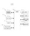
図1は、本発明の第一の実施形態に係る自律自動測位機能付きGPS搭載携帯電話機100が第三者の位置測位を行う測位システムの一例を示すブロック図である。
【0028】
本測位システムは、測位者(甲)のGPS搭載携帯電話機である第一の携帯電話機101と、被測位者(乙)のGPS搭載携帯電話機である第二の携帯電話機109と、第一の携帯電話機101と第二の携帯電話機109の各々のGPS部4に電波を送信しているGPS衛星108a、108b、108c及び108dと、第一の携帯電話機101と第二の携帯電話機109の各々及び他の携帯電話機103の携帯電話送受信部2がアクセスする携帯電話網102と、インターネット網106を介して第一の携帯電話機101からの第三者測位要求を受けたときに、対象端末である第二の携帯電話機109に位置測位の指示要求を出し、また、対象端末から受けた位置情報を測位要求を出した第一の携帯電話機101に送信するサーバー107と、から構成されている。
【0029】
第一及び第二の携帯電話機101、109は何れも上述の第一の実施形態に係る携帯電話機100からなる。
【0030】
以下、図1に示した測位システムにおける第一の携帯電話機101の動作の一例について説明する。
【0031】
第一の携帯電話機101に内蔵されたGPS部4は、GPS衛星108a、108b及び108cからの信号を断続的に受信する。
【0032】
第一の携帯電話機101は、無線を介して携帯電話網102に接続されており、携帯電話機103や公衆電話網(PSTN)104に接続された電話端末105と音声通信を行う。あるいは、第一の携帯電話機101は、インターネット網106に接続されたサーバー107とデータ通信を行ったり、または、サーバー107を介して被測位端末機である第二の携帯電話機109と位置情報のデータ通信を行う。
【0033】
第二の携帯電話機109は、サーバー107から位置情報の受信の要求があった場合には、GPS衛星108b、108c及び108dからの信号を受信し、自機の位置情報をサーバー107に返信する。
【0034】
図3は、第一の携帯電話機101の被測位者追跡及び被測位者接近報知を行うまでの動作を示すフローチャートであり、図4は、被測位者が第一の携帯電話機101に接近したときの状況を示す概念図である。以下、第一の携帯電話機101の第三者追跡及び第三者接近報知の動作について、図3及び図4を用いて説明する。
【0035】
まず、被測位者を決定するために、測位者である第一の携帯電話機101において、被測位者の第二の携帯電話機109のID情報(例えば、電話番号)を入力部7を介して直接的にキー入力し、あるいは、記憶部10に保存されているアドレス帳から選択して入力する。ここで決定した被測位者のID情報を記憶部10に記憶させ(ステップS101)、これから実施する測位が何番目の測位であるかを示す内部フラグ「flag」を「0」に初期化する(ステップS102)。
【0036】
次に、先に入力した被測位者のID情報を含むデータを携帯電話送受信部2において変調した後、被測位者の測位を要求する被測位者測位要求信号としてサーバー107に送信する(ステップS103)。
【0037】
その後、第一の携帯電話機101は、被測位者の緯度及び経度を示す情報からなる被測位者の現在地位置情報Y1をサーバー107から受信し、その受信データを携帯電話送受信部2において復調した後、記憶部10に保存する(ステップS104)。
【0038】
被測位者の位置情報Y1を受信すると、制御部5は、タイマー部6の被測位者測位間隔計測用の第一タイマー6Aの動作を開始させる(ステップS105)。
【0039】
次に、携帯電話機101は、自機の現在位置を測位する。すなわち、GPSアンテナ3を介してGPS衛星108a、108b及び108cからの信号を受信し、GPS部4において、自機の緯度及び経度を示す情報からなる自機の現在地位置情報X1を算出し、記憶部10に自己位置情報として保存する(ステップS106)。
【0040】
自己位置を算出した後、制御部5は、タイマー部6の自己測位間隔計測用の第二タイマー6Bを動作させる(ステップS107)。
【0041】
被測位者の現在位置情報Y1と自己位置情報X1を取得した後、制御部5は、これらのデータを距離計算部8に入力し、被測位者と自機との間の直線距離を計算する(ステップS108)。
【0042】
このようにして算出した被測位者と自機との間の直線距離に応じて、被測位者が測位者の近傍に近付いているか否かが判定される。例えば、測位者を中心とする半径100mの円内を測位者の近傍、すなわち、報知エリアとして設定した場合には、被測位者が報知エリア内にいるか否かが判定される(ステップS109)。
【0043】
距離計算部8において算出された被測位者と測位者との間の距離が100m以内であれば(ステップS109のYES)、制御部5は、タイマー部6の動作中のタイマー、すなわち、第一タイマー6A及び第二タイマー6Bを停止させる(ステップS110)。
【0044】
次いで、制御部5は、第一タイマー6A及び第二タイマー6Bをリセットするとともに、記憶部10に保存した被測位者のID情報、被測位者の現在位置情報Y1及び自己位置情報X1を削除する(ステップS111)。
【0045】
次いで、制御部5は、報知部11を作動させることにより、測位者に対して、被測位者が測位者の100m以内の近傍にいる事実を報知する(ステップS112)。
【0046】
距離計算部8において算出された測位者と被測位者との間の距離が100mよりも大きく(ステップS109のNO)、かつ、内部フラグflagが0であれば(ステップS113のYES)、内部フラグflagを1にした後(ステップS114)、2番目の測位の実施に移る。
【0047】
2番目の測位は、1番目の測位と同様に、まず、被測位者のその後の位置情報を測位することから開始される。
【0048】
制御部5は、記憶部10に保存してある被測位者のID情報を呼び出し、その被測位者のID情報を携帯電話送受信部2において変調した後、被測位者測位要求信号としてサーバー107に送信する(ステップS115)。
【0049】
1番目の測位の場合と同様に、サーバー107から被測位者の現在位置情報Y2を受信すると(ステップS116)、制御部5は、今まで動作していたタイマー部6の第一タイマー6Aを停止させ(ステップS117)、第一タイマー6Aの値及び受信した被測位者の現在位置情報Y2を記憶部10に保存する。
【0050】
次に、2番目の自機の位置の測位を行うため、制御部5は、GPSアンテナ3を介してGPSデータを受信する。GPS部4は、受信したデータに基づいて、自機の緯度及び経度を示す自己位置情報X2を算出し(ステップS118)、動作中のタイマー部6の第二タイマー6Bを停止させる(ステップS119)。
【0051】
制御部5は、第二タイマーBの値及び算出した自己位置情報X2を記憶部10に保存する。
【0052】
2番目の被測位者位置情報Y2と自己位置情報X2とを取得した後、制御部5は、これらのデータを距離計算部8に入力し、自機と被測位者との間の直線距離を計算する(ステップS108)。
【0053】
距離計算部8において算出された被測位者と測位者との間の距離が100m以内であれば(ステップS109のYES)、制御部5は、タイマー部6の動作中のタイマーを停止させる(ステップS110)。ただし、今回は動作中のタイマーはない。
【0054】
次いで、制御部5は、第一タイマー6A及び第二タイマー6Bをリセットするとともに、記憶部10に保存した被測位者のID情報、被測位者の現在位置情報Y1及びY2並びに自己位置情報X1及びX2を削除する(ステップS111)。
【0055】
次いで、制御部5は、報知部11を作動させることにより、測位者に対して、被測位者が測位者の100m以内の近傍にいる事実を報知する(ステップS112)。
【0056】
距離計算部8において算出された被測位者と測位者との間の距離が100mよりも大きい場合には(ステップS109のNO)、この段階では内部フラグflagが1であるので(ステップS113のNO)、制御部5は、被測位者及び測位者の移動速度Vb1及びVa1の計算処理を行う。
【0057】
すなわち、制御部5は、記憶部10から被測位者及び測位者の2回分の測位データY1、Y2、X1、X2及び各々の測位間隔時間データ(第一タイマー6Aの値及び第二タイマー6Bの値)を呼び出し、速度/時間計算部9において、被測位者及び測位者の移動速度Vb1及びVa1を算出する(ステップS120)。
【0058】
次に、制御部5は、図4に示すように、報知エリアと2番目の被測位者の現在位置情報Y2が示す位置との間の距離Sを被測位者及び測位者が各々の移動速度Vb1及びVa1で互いに向かい合って移動していると仮定した場合に、被測位者が報知エリアに到達する時間tを速度/時間計算部9において推定する(ステップS121)。
【0059】
例えば、Vb1=15km/h、Va1=5km/h、S=10.1kmである場合には、
t=(10.1−0.1)/(15+5)=0.5
となる。すなわち、被測位者が報知エリアに到達するのは30分後と推定される。
【0060】
到達時間tを算出した後、制御部5は、タイマー部6の第三タイマー6Cに到達時間tをセットすることにより、第三タイマー6Cの動作を開始する(ステップS122)。
【0061】
第三タイマー6Cの動作開始から時間tが経過し、第三タイマー6Cの値が0になると(ステップS123のYES)、制御部5は、第三タイマー6Cを停止させるとともに、第一タイマー6A及び第二タイマー6Bの動作を開始させ(ステップS124)、被測位者の現在位置の測位を行う。
【0062】
次いで、制御部5は、記憶部10に保存してある測位者及び被測位者それぞれの1番目測位データを削除し、2番目測位データを1番目測位データとして記憶部10に再保存する(ステップS125)。
【0063】
次に、前述の2番目の測位からの動作と同様にして、被測位者及び測位者の位置情報を取得する(ステップS115−S119)。
【0064】
測位者と被測位者との間の距離が100m以内であれば、制御部5は、報知部11を作動させ(ステップS108−S112)、測位者と被測位者との間の距離が100mを超えている場合には(ステップS109のNO、ステップS113のNO)、制御部5は、速度/時間計算部9において被測位者及び測位者の速度をそれぞれ算出する(ステップS120)。
【0065】
今回の速度算出においては、被測位者及び測位者の移動時間として、前回推定した到達時間と第一タイマー6Aの値との和及び前回推定した到達時間と第二タイマー6Bの値との和をそれぞれ用いる。また、起点位置としては記憶部10に入れ替え保存した1番目の測位データを、終点位置としては今回測位し、記憶部10に新たに2番目のデータとして保存した測位データを用いて、速度を算出する。
【0066】
その後、被測位者と測位者との間の距離と各々の移動速度とに基づいて、前回と同様にして、到達時間を推定し(ステップS121)、次回の再測位の時間を決定する。
【0067】
以下、被測位者が測位者の報知エリア内に到達するまで同様の動作を繰り返す(ステップS122からステップS109のYESまで)。
【0068】
図5は、本発明の第二の実施形態に係る自律自動測位機能付きGPS搭載携帯電話機200の構成を示すブロック図である。
【0069】
図2を参照すると、本実施形態に係る携帯電話機100は、携帯電話網からデータを受信し、さらに、携帯電話網にデータを送信するための携帯電話用アンテナ1と、アンテナ1から受信したデータを復調し、または、送信するデータを変調する携帯電話送受信部2と、GPS衛星から送信される電波をキャッチするGPSアンテナ3と、GPSアンテナ3を介して受信したGPSデータに基づいて、携帯電話機100の現在位置を示す経度及び緯度を含む位置情報を算出するGPS部4と、携帯電話機100の各種動作の制御を行う制御部5と、測位者(すなわち、携帯電話機100)及び被測位者の移動速度の推定に用いる測位間隔時間を計測するとともに、被測位者の位置を再測位するまでの時間を刻むタイマー部6と、被測位者ID(電話番号)を選択し、または、キーで入力する入力部7と、測位者と被測位者との間の2地点間距離を計算する距離計算部8と、測位者及び被測位者の移動速度並びに被測位者の再測位タイミング時間を計算する速度/時間計算部9と、被測位者ID(電話番号)及び測位した位置情報その他のデータを記憶する記憶部10と、被測位者が測位者の近傍エリアに到達したことを測位者に知らせる報知部11と、速度測定スイッチ21と、移動位置計算部22と、から構成されている。
【0070】
タイマー部6は、第一の実施形態に係る携帯電話機100の場合と同様に、第一タイマー6A、第二タイマー6B及び第三タイマー6Cを備えている。
【0071】
また、報知部11は、第一の実施形態に係る携帯電話機100の場合と同様に、音声を発して測位者に知らせる音声発生手段、光を発して測位者に知らせる発光手段、振動することにより測位者に知らせる振動手段のうちの少なくとも何れか一つを備えている。
【0072】
すなわち、本実施形態に係る携帯電話機200は、第一の実施形態に係る携帯電話機100と比較して、速度測定スイッチ21と移動位置計算部22とを追加的に備えている。
【0073】
図6は、第二の実施形態における第一の携帯電話機101の被測位者追跡及び被測位者接近報知を行うまでの動作を示す部分的なフローチャートである。図3に示した第一の実施形態における第一の携帯電話機101の動作と比較して、ステップS201−S209が新たに追加されている。
【0074】
被測位者の次回測位時間を推定した後、実際に再測位を行うまでの間(ステップS123のNOからステップS201のNOまでの間)に測位者の移動速度が大きく変化する場合がある。このような場合に、測位者が自己速度を再計算したいと考えたときには(ステップS201のYES)、測位者は、携帯電話機200の速度測定スイッチ21を押下することにより、以下のように、自己速度を再計算し、それを次回の被測位者測定時間に反映させることができる。
【0075】
速度測定スイッチ21が押下されると(ステップS202)、携帯電話機200は、GPSアンテナ3を介してGPS衛星108a、108b、108cからの信号を受信し、GPS部4において自機の緯度及び経度を示す情報からなる自己位置情報X3を算出し、記憶部10に保存する(ステップS203)。
【0076】
その後、制御部5は、タイマー部6の自己測位間隔計測用の第二タイマー6Bを動作させる(ステップS204)。
【0077】
同様にして、次の自己位置測位を開始し、自己位置情報X4を算出した後、記憶部10に保存する(ステップS205)。
【0078】
2回の自己位置情報X3及びX4の算出が完了すると、制御部5は、タイマー部6の第二タイマー6B及び第三タイマー6Cを停止させる(ステップS206)。
【0079】
制御部5は、この時のタイマー部6の第三タイマー6Cの値を読み出す(ステップS207)。
【0080】
次いで、制御部5は、移動位置計算部22において、この第三タイマー6Cの値と前回算出した被測位者の速度データと自己位置情報X2と被測位者の現在位置情報Y2とに基づいて、図7に示すように、被測位者が直線的に移動したと仮定した場合の現時点における移動位置Y3を推定する(ステップS208)。
【0081】
この被測位者の推定移動位置Y3と、被測位者の移動速度Vb1と、2つの自己位置情報X3及びX4から計算した測位者の移動速度Va2と、現在の自己位置情報X4とに基づいて、制御部5は、速度/時間計算部9において、被測位者の報知エリアまでの到達時間を再計算する(ステップS209)。
【0082】
制御部5は、到達時間を算出すると、これをタイマー部6の第三タイマー6Cに入力し(ステップS122)、到達時間が経過した後(ステップS123のYES)、第三タイマー6Cを停止させ、被測位者の現在位置の測位を行う(ステップS125)。
【0083】
以上のように、本実施形態によれば、途中で測位者の移動速度が変化した場合であっても、その速度変化を吸収することができ、次回の被測位者の測位タイミングに反映させることができる。
【0084】
【発明の効果】
以上のように、本発明によれば、次のような効果を得ることができる。
【0085】
第1の効果は、被測位者(第三者)の接近を報知するために、被測位者(第三者)の位置を常に測位する必要がないことである。
【0086】
その理由は、第三者の移動速度と測位者の移動速度とを算出することにより、第三者が接近する時間を推定し、その推定時刻を次の測位時と定めるからである。
【0087】
第2の効果は、GPS測位に伴う消費電流を軽減することができることである。
【0088】
その理由は、第三者の接近推定時刻を計算しているため、それ以外に不必要なGPS測位を行うことがないためである。
【0089】
第3の効果は、被測位者の測位の際に、被測位者の端末装置にGPS測位をさせることに伴う負荷を軽減することができることである。
【0090】
その理由は、被測位者を測位するタイミングを最適に決定しているため、被測位者の端末装置に不要な測位を行わせる必要性を発生させないためである。
【図面の簡単な説明】
【図1】本発明の第一の実施形態に係る携帯電話機を用いた測位システムのブロック図である。
【図2】本発明の第一の実施形態に係る携帯電話機のブロック図である。
【図3】本発明の第一の実施形態に係る携帯電話機の測位システムにおける動作を示すフローチャートである。
【図4】測位者と被測位者との位置関係を示す概念図である。
【図5】本発明の第二の実施形態に係る携帯電話機のブロック図である。
【図6】本発明の第二の実施形態に係る携帯電話機の測位システムにおける動作を示す部分的なフローチャートである。
【図7】測位者と被測位者との位置関係を示す概念図である。
【符号の説明】
1 携帯電話用アンテナ
2 携帯電話送受信部
3 GPSアンテナ
4 GPS部
5 制御部
6 タイマー部
7 入力部
8 距離計算部
9 速度/時間計算部
10 記憶部
11 報知部
21 速度測定スイッチ
22 移動位置計算部
100 第一の実施形態に係る携帯電話機
101 第一の携帯電話機
102 携帯電話網
103 携帯電話端末
104 公衆電話網
105 電話端末
106 インターネット網
107 サーバー
108a、108b、108c GPS衛星
109 第二の携帯電話機
200 第二の実施形態に係る携帯電話機[0001]
BACKGROUND OF THE INVENTION
The present invention has a function of measuring the positions of its own device and a person to be measured, and is capable of detecting the approach of the person to be measured to the own device, and a portable information terminal device thereof. It is related with the method of alert | reporting to a positioning person the approach of a to-be-measured person to a positioning person.
[0002]
[Prior art]
Various portable information terminal devices that can inform the user of the position of the other party by installing a GPS (Global Positioning System) have been proposed.
[0003]
For example, Japanese Patent Application Laid-Open No. 9-178833 proposes a terminal device that can inform the position of the other party.
[0004]
When a signal requesting the current position of the second terminal device is output from the first terminal device, the first base station closest to the first terminal device transfers this signal to the server. When the server receives this signal, it receives the current position of the second terminal device via the second base station, and a map including the current positions of the first and second terminal devices from the database built in the server. Data is read and the map data is transmitted to the first and second terminal devices.
[0005]
Further, the mobile terminal device proposed in Japanese Patent Laid-Open No. 9-189562 detects the position of the own device based on the signal received by the GPS antenna, reads out the map information based on the detected position from the memory, and displays the display screen. The location of the device is displayed together with the map information. Further, the mobile terminal device receives position and movement direction information from other terminal devices, outputs it to the GPS device, and also displays the position of the other terminal device on the display screen.
[0006]
Japanese Patent Laid-Open No. 11-2675 proposes a relative position detection system for detecting a relative position between a first moving body and a second moving body using data transmitted from a plurality of positioning satellites. Yes. In this relative position detection system, the positioning means and the second moving body of the first moving body are selected so as to select and use a positioning satellite having a high common usage between the first moving body and the second moving body. Control the positioning means.
[0007]
Japanese Patent Application Laid-Open No. 2001-59740 proposes a mobile communication device that can obtain position information of the other party. When the user of the first mobile phone inputs the telephone number of the second mobile phone to the first mobile phone and presses the “position display key”, the first mobile phone receives the phone number and the position request signal. Is transmitted to the control station via the base station. The control station retrieves the position data of the second mobile phone from the database and transmits it to the first mobile phone. After receiving the position data, the first mobile phone inputs its own position data. Further, the first mobile phone reads out map data in the vicinity of the position of the second mobile phone from the memory, and displays the map and the positions of the first and second mobile phones superimposed on the display screen.
[0008]
[Problems to be solved by the invention]
In the above-described conventional portable information terminal device, in order to detect the approach of the other party while positioning the other party, the other party is periodically requested to provide information indicating the current position, I had to keep track of that trend.
[0009]
For this reason, even when the other party has not yet approached, the positioning person often requests the other party to provide information indicating the current position. For this reason, the other party had to perform GPS positioning many times, and was burdened with work, money, and operational load.
[0010]
In addition, as a positioning person, by causing unnecessary positioning to be performed on the other party, a similar load was imposed.
[0011]
The present invention has been made in view of such problems, and an object of the present invention is to provide a mobile phone that can detect the position of the other party without performing unnecessary positioning.
[0012]
[Means for Solving the Problems]
In order to achieve this object, the present invention measures the positionee, and when the positionee enters a notification area set around the positioner, the positioner is notified of the positionee. GPS-equipped mobile phone that reports entry into the notification areaThe time when the measured person reaches the notification area is estimated at a stage before the measured person reaches the notification area, and when the estimated time has elapsed after the estimation is performed, A GPS-equipped mobile phone characterized by positioning a positionee I will provide a.
[0014]
The time for the person to be measured to reach the notification area is, for example, calculating the distance between the notification area and the person to be measured and the moving speed of the person to be measured and the person to be measured, and these distances. And can be estimated based on the moving speed.
[0015]
The GPS mobile phone recalculates and recalculates the moving speed after the change of the positioning person when the moving speed of the positioning person changes after estimating the time for the measured person to reach the notification area. On the basis of the travel speed, the time for the positionee to reach the notification area can be re-estimated.
[0016]
Furthermore, the present invention is a method for detecting the approach of a measured person to a positioning person using a GPS-equipped mobile phone, the process of positioning the measured person, and the positioning person set around the positioning person A process of determining whether or not the user has entered the notification area, and when the person to be measured enters the notification area, the person who has entered the notification area is notified of the person who has entered the notification area. Process,The process of estimating the time required for the positionee to reach the notification area at a stage before the positionee reaches the notification area, and the position measurement when the estimated time has elapsed since the estimation was performed. The process of positioning the person, A method comprising:
[0018]
The method includes calculating a distance between the notification area and the measured person, a moving speed of the positioning person and the measured person, and the measured position based on the distance and the moving speed. It is preferable that the method includes estimating the time for the person to reach the notification area.
[0019]
The method includes a step of recalculating the moving speed after the change of the positioning person when the moving speed of the positioning person changes after estimating the time for the measured person to reach the notification area; It is preferable that the method further comprises a step of re-estimating the time for the positionee to reach the notification area based on the travel speed.
[0020]
According to the present invention, in a mobile phone equipped with a GPS, when a person to be measured reaches a notification area set around the person who is positioning, that fact is notified to the positioner. For this reason, the positioning person can recognize the approach of the positioning person without being conscious of himself / herself.
[0021]
In the present invention, after the first position of the current position of the positionee is measured, the current position of the positionee is again measured when a predetermined time has elapsed. For this reason, it is possible to avoid performing unnecessary positioning in order to confirm the current position of the person to be measured.
[0022]
In addition, even if the moving speed of the positioning person changes and the approaching time of the first estimated person changes, the approaching time of the positioning person is estimated again from the moving speed of the positioning person and the positioning person. Therefore, it is not necessary to perform unnecessarily many positioning.
[0023]
DETAILED DESCRIPTION OF THE INVENTION
FIG. 2 is a block diagram showing a configuration of the GPS-equipped
[0024]
Referring to FIG. 2, a
[0025]
The
[0026]
In addition, the
[0027]
FIG. 1 is a block diagram showing an example of a positioning system in which a GPS-equipped
[0028]
This positioning system includes a first
[0029]
Each of the first and second
[0030]
Hereinafter, an example of the operation of the first
[0031]
The
[0032]
The first
[0033]
When there is a request for receiving location information from the
[0034]
FIG. 3 is a flowchart showing the operation of the first
[0035]
First, in order to determine a person to be measured, the first
[0036]
Next, the mobile terminal transmitting / receiving
[0037]
Thereafter, the first
[0038]
When receiving the position information Y1 of the person to be measured, the
[0039]
Next, the
[0040]
After calculating the self position, the
[0041]
After acquiring the current position information Y1 and the self-position information X1 of the person to be measured, the
[0042]
It is determined whether or not the person to be measured is approaching the vicinity of the person to be measured in accordance with the straight line distance between the person to be measured and his / her own device thus calculated. For example, when a circle with a radius of 100 m centering on the positioning person is set as the vicinity of the positioning person, that is, as the notification area, it is determined whether or not the measured person is in the notification area (step S109).
[0043]
If the distance between the measured person and the position person calculated by the
[0044]
Next, the
[0045]
Next, the
[0046]
If the distance between the positioning person and the person to be measured calculated by the
[0047]
Similar to the first positioning, the second positioning is started by first positioning the subsequent position information of the person to be measured.
[0048]
The
[0049]
As in the case of the first positioning, when receiving the current position information Y2 of the measured person from the server 107 (step S116), the
[0050]
Next, the
[0051]
The
[0052]
After acquiring the second positionee position information Y2 and the self-position information X2, the
[0053]
If the distance between the measured person and the position person calculated by the
[0054]
Next, the
[0055]
Next, the
[0056]
If the distance between the measured person and the position person calculated by the
[0057]
That is, the
[0058]
Next, as shown in FIG. 4, the
[0059]
For example, when Vb1 = 15 km / h, Va1 = 5 km / h, and S = 10.1 km,
t = (10.1-0.1) / (15 + 5) = 0.5
It becomes. That is, it is estimated that it is 30 minutes after the positionee reaches the notification area.
[0060]
After calculating the arrival time t, the
[0061]
When the time t has elapsed from the start of the operation of the
[0062]
Next, the
[0063]
Next, in the same manner as the operation from the second positioning described above, the position information of the positioning subject and the positioning person is acquired (steps S115 to S119).
[0064]
If the distance between the positioning person and the positioning person is within 100 m, the
[0065]
In this speed calculation, as the movement time of the positionee and the positioning person, the sum of the previously estimated arrival time and the value of the
[0066]
Thereafter, based on the distance between the measured person and the positioning person and the respective moving speeds, the arrival time is estimated similarly to the previous time (step S121), and the next re-positioning time is determined.
[0067]
Hereinafter, the same operation is repeated until the measured person reaches the informing area of the positioning person (from step S122 to YES in step S109).
[0068]
FIG. 5 is a block diagram showing a configuration of a GPS-equipped
[0069]
Referring to FIG. 2, a
[0070]
The
[0071]
In addition, as in the case of the
[0072]
That is, the
[0073]
FIG. 6 is a partial flowchart showing an operation of the first
[0074]
There is a case where the moving speed of the positioning person changes greatly during the period from when the next positioning time of the positioning person is estimated until the actual positioning is performed again (from NO at step S123 to NO at step S201). In such a case, when the positioning person wants to recalculate his / her own speed (YES in step S201), the positioning person presses the
[0075]
When the
[0076]
Thereafter, the
[0077]
Similarly, the next self-positioning is started, self-position information X4 is calculated, and then stored in the storage unit 10 (step S205).
[0078]
When the calculation of the self-position information X3 and X4 twice is completed, the
[0079]
The
[0080]
Next, the
[0081]
Based on the estimated movement position Y3 of the positioning person, the movement speed Vb1 of the positioning person, the movement speed Va2 of the positioning person calculated from the two self-position information X3 and X4, and the current self-position information X4, In the speed /
[0082]
After calculating the arrival time, the
[0083]
As described above, according to the present embodiment, even if the moving speed of the positioning person changes midway, the speed change can be absorbed and reflected in the positioning timing of the next positioning person. Can do.
[0084]
【The invention's effect】
As described above, according to the present invention, the following effects can be obtained.
[0085]
The first effect is that there is no need to always measure the position of the person to be measured (third party) in order to notify the approach of the person to be measured (third party).
[0086]
The reason is that by calculating the moving speed of the third party and the moving speed of the positioning person, the time for the third person to approach is estimated, and the estimated time is determined as the next positioning time.
[0087]
The second effect is that current consumption associated with GPS positioning can be reduced.
[0088]
The reason is that since the estimated approach time of a third party is calculated, unnecessary unnecessary GPS positioning is not performed.
[0089]
A third effect is that it is possible to reduce a load caused by causing the terminal device of the person to be measured to perform GPS positioning when the person to be measured is positioning.
[0090]
The reason is that since the timing for positioning the measured person is optimally determined, it is not necessary to cause the terminal apparatus of the measured person to perform unnecessary positioning.
[Brief description of the drawings]
FIG. 1 is a block diagram of a positioning system using a mobile phone according to a first embodiment of the present invention.
FIG. 2 is a block diagram of the mobile phone according to the first embodiment of the present invention.
FIG. 3 is a flowchart showing an operation in the positioning system of the mobile phone according to the first embodiment of the present invention.
FIG. 4 is a conceptual diagram showing a positional relationship between a positioning person and a positioning person.
FIG. 5 is a block diagram of a mobile phone according to a second embodiment of the present invention.
FIG. 6 is a partial flowchart showing an operation in the positioning system of the mobile phone according to the second embodiment of the present invention.
FIG. 7 is a conceptual diagram showing a positional relationship between a positioning person and a positioning person.
[Explanation of symbols]
1 Mobile phone antenna
2 Mobile phone transceiver
3 GPS antenna
4 GPS section
5 Control unit
6 Timer section
7 Input section
8 Distance calculator
9 Speed / time calculator
10 storage unit
11 Notification unit
21 Speed measurement switch
22 Moving position calculator
100 Mobile phone according to the first embodiment
101 First mobile phone
102 Mobile phone network
103 Mobile phone terminal
104 public telephone network
105 Telephone terminal
106 Internet network
107 servers
108a, 108b, 108c GPS satellites
109 Second mobile phone
200 Mobile phone according to the second embodiment
Claims (6)
Translated fromJapanese前記被測位者が前記報知エリアに到達する時間を、前記被測位者が前記報知エリアに到達する前の段階で推定し、該推定を行ってからその推定時間が経過した時に前記被測位者を測位することを特徴とするGPS搭載携帯電話機。GPS equipped to measure the positionee and notify the positioning person of the positionee's entry into the notification area when the positionee enters the notification area set around the positioner. A mobile phone,
Estimating the time for the positionee to reach the notification area at a stage before the positionee reaches the notification area, and when the estimated time has passed since the estimation, A GPS-equipped mobile phonecharacterized by positioning .
被測位者を測位する過程と、The process of positioning the subject,
前記被測位者が測位者の周囲に設定された報知エリア内に進入したか否かを判定する過程と、A process of determining whether or not the measured person has entered a notification area set around the positioning person;
前記被測位者が前記報知エリアに進入したときに、前記測位者に前記被測位者の前記報知エリア内への進入を報知する過程と、When the measured person enters the notification area, a process of notifying the positioning person of the entry of the measured person into the notification area;
前記被測位者が前記報知エリアに到達する時間を、前記被測位者が前記報知エリアに到達する前の段階で推定する過程と、A process of estimating the time required for the positionee to reach the notification area at a stage before the positionee reaches the notification area;
前記推定を行ってからその推定時間が経過した時に前記被測位者を測位する過程と、A process of positioning the positionee when the estimated time has elapsed since the estimation was performed;
を備えることを特徴とする方法。A method comprising the steps of:
前記距離及び前記移動速度に基づいて、前記被測位者が前記報知エリアに到達する時間を推定する過程と、
を備えることを特徴とする請求項4に記載の方法。Calculating the distance between the notification area and the measured person, and the moving speed of the measured person and the measured person;
A process of estimating a time for the positionee to reach the notification area based on the distance and the moving speed;
The method ofclaim 4, comprising :
再計算された移動速度に基づいて、前記被測位者が前記報知エリアに到達する時間を再推定する過程と、
を備えることを特徴とする請求項4または5に記載の方法。After estimating the time for the positionee to reach the notification area, if the moving speed of the positioning person has changed, the process of recalculating the moving speed after the change of the positioning person,
Based on the recalculated moving speed, a process of re-estimating the time for the positionee to reach the notification area;
The method accordingto claim 4 or 5 , comprising:
Priority Applications (2)
| Application Number | Priority Date | Filing Date | Title |
|---|---|---|---|
| JP2002133580AJP4051699B2 (en) | 2002-05-09 | 2002-05-09 | GPS mobile phone |
| US10/429,876US20030211853A1 (en) | 2002-05-09 | 2003-05-06 | GPS-mounted mobile telephone |
Applications Claiming Priority (1)
| Application Number | Priority Date | Filing Date | Title |
|---|---|---|---|
| JP2002133580AJP4051699B2 (en) | 2002-05-09 | 2002-05-09 | GPS mobile phone |
Publications (2)
| Publication Number | Publication Date |
|---|---|
| JP2003329760A JP2003329760A (en) | 2003-11-19 |
| JP4051699B2true JP4051699B2 (en) | 2008-02-27 |
Family
ID=29397429
Family Applications (1)
| Application Number | Title | Priority Date | Filing Date |
|---|---|---|---|
| JP2002133580AExpired - Fee RelatedJP4051699B2 (en) | 2002-05-09 | 2002-05-09 | GPS mobile phone |
Country Status (2)
| Country | Link |
|---|---|
| US (1) | US20030211853A1 (en) |
| JP (1) | JP4051699B2 (en) |
Families Citing this family (18)
| Publication number | Priority date | Publication date | Assignee | Title |
|---|---|---|---|---|
| US7474896B2 (en) | 2000-07-14 | 2009-01-06 | Norman Mohi | Locating system and method |
| US9392406B2 (en) | 2005-02-03 | 2016-07-12 | Trueposition, Inc. | Method and system for location-based monitoring of a mobile device |
| US8565788B2 (en)* | 2005-02-03 | 2013-10-22 | Mexens Intellectual Property Holding Llc | Method and system for obtaining location of a mobile device |
| US8065079B2 (en)* | 2005-03-31 | 2011-11-22 | Qualcomm Incorporated | System and method for indicating reminders via a portable computing device |
| JP4948594B2 (en)* | 2007-03-07 | 2012-06-06 | パナソニック株式会社 | Portable terminal device and portable terminal system |
| JP2011252720A (en)* | 2010-05-31 | 2011-12-15 | Ntt Docomo Inc | Positioning device and positioning method |
| US9332393B2 (en) | 2011-12-23 | 2016-05-03 | Elwha Llc | Computational systems and methods for locating a mobile device |
| US9357496B2 (en) | 2011-12-23 | 2016-05-31 | Elwha Llc | Computational systems and methods for locating a mobile device |
| US9591437B2 (en) | 2011-12-23 | 2017-03-07 | Elwha Llc | Computational systems and methods for locating a mobile device |
| US9031584B2 (en) | 2011-12-23 | 2015-05-12 | Elwha, Llc | Computational systems and methods for locating a mobile device |
| US9161310B2 (en)* | 2011-12-23 | 2015-10-13 | Elwha Llc | Computational systems and methods for locating a mobile device |
| US9194937B2 (en) | 2011-12-23 | 2015-11-24 | Elwha Llc | Computational systems and methods for locating a mobile device |
| US9154908B2 (en) | 2011-12-23 | 2015-10-06 | Elwha Llc | Computational systems and methods for locating a mobile device |
| US9482737B2 (en) | 2011-12-30 | 2016-11-01 | Elwha Llc | Computational systems and methods for locating a mobile device |
| US9087222B2 (en) | 2011-12-23 | 2015-07-21 | Elwha Llc | Computational systems and methods for locating a mobile device |
| US20130303195A1 (en)* | 2011-12-23 | 2013-11-14 | Elwha Llc | Computational Systems and Methods for Locating a Mobile Device |
| US9801033B1 (en)* | 2016-04-08 | 2017-10-24 | Vivint, Inc. | Family member tracking |
| JP2024157966A (en)* | 2023-04-26 | 2024-11-08 | キヤノン株式会社 | DISPLAY CONTROL SYSTEM, INFORMATION PROCESSING APPARATUS, METHOD, AND COMPUTER PROGRAM |
Family Cites Families (11)
| Publication number | Priority date | Publication date | Assignee | Title |
|---|---|---|---|---|
| JPH0822247A (en)* | 1994-07-06 | 1996-01-23 | Sony Corp | Navigation device |
| JPH09189562A (en)* | 1996-01-11 | 1997-07-22 | Canon Inc | Position recognition display device and control method thereof |
| CA2265875C (en)* | 1996-09-09 | 2007-01-16 | Dennis Jay Dupray | Location of a mobile station |
| AU6453598A (en)* | 1997-03-10 | 1998-09-29 | Global Research Systems, Inc. | Advanced notification systems and methods utilizing a computer network |
| JP2868500B1 (en)* | 1998-02-13 | 1999-03-10 | 日本電気移動通信株式会社 | Mobile station location notification system and method |
| JP3707311B2 (en)* | 1999-08-25 | 2005-10-19 | 株式会社デンソー | Mobile communication device and mobile communication system |
| JP3424626B2 (en)* | 1999-11-26 | 2003-07-07 | 日本電気株式会社 | Moving object collision prediction device |
| FI108372B (en)* | 2000-06-30 | 2002-01-15 | Nokia Corp | Method and apparatus for position measurement |
| JP2002190091A (en)* | 2000-12-20 | 2002-07-05 | Pioneer Electronic Corp | Travel time setting method and apparatus, and route calculation method and apparatus using the same |
| US6882309B2 (en)* | 2001-07-18 | 2005-04-19 | Fast Location. Net, Llc | Method and system for processing positioning signals based on predetermined message data segment |
| US20030030561A1 (en)* | 2001-08-08 | 2003-02-13 | Byron Yafuso | Method and apparatus for wireless tracking and communication |
- 2002
- 2002-05-09JPJP2002133580Apatent/JP4051699B2/ennot_activeExpired - Fee Related
- 2003
- 2003-05-06USUS10/429,876patent/US20030211853A1/ennot_activeAbandoned
Also Published As
| Publication number | Publication date |
|---|---|
| US20030211853A1 (en) | 2003-11-13 |
| JP2003329760A (en) | 2003-11-19 |
Similar Documents
| Publication | Publication Date | Title |
|---|---|---|
| JP4051699B2 (en) | GPS mobile phone | |
| KR101353755B1 (en) | Satellite positioning system receivers and methods | |
| US9232356B2 (en) | Locator system | |
| CN1288423C (en) | Position message management system | |
| KR100913881B1 (en) | System and method for providing location information of a portable communication terminal | |
| KR20060008917A (en) | Location system and method | |
| JP2005223436A (en) | Mobile terminal and position information exchange system | |
| KR20050099983A (en) | Mobile information terminal and communication system | |
| KR20030046656A (en) | Method and Device for Automatically Notifying Location-Information using Mobile Communication Terminal with GPS Receiving Function | |
| US20050020241A1 (en) | Locator system | |
| CN100442910C (en) | Location reminder method | |
| JP4379704B2 (en) | Radio wave environment information processing server, portable terminal, radio wave environment notification system, and radio wave environment notification method | |
| KR101503833B1 (en) | Communication terminal and method for managing location information of base station thereof | |
| KR20030053928A (en) | Method for informing of arrival/exit of specific area and mobile phone implementing the same | |
| JP3609017B2 (en) | Communications system | |
| KR100558984B1 (en) | Control Method of Vehicle Mounted Navigation System | |
| KR100583425B1 (en) | Location information service method through mobile communication terminal | |
| JP2011101239A (en) | Position information acquisition device of portable terminal device and program | |
| KR20070045002A (en) | How to provide route information |
Legal Events
| Date | Code | Title | Description |
|---|---|---|---|
| A621 | Written request for application examination | Free format text:JAPANESE INTERMEDIATE CODE: A621 Effective date:20050422 | |
| A131 | Notification of reasons for refusal | Free format text:JAPANESE INTERMEDIATE CODE: A131 Effective date:20070727 | |
| A521 | Written amendment | Free format text:JAPANESE INTERMEDIATE CODE: A523 Effective date:20070919 | |
| TRDD | Decision of grant or rejection written | ||
| A01 | Written decision to grant a patent or to grant a registration (utility model) | Free format text:JAPANESE INTERMEDIATE CODE: A01 Effective date:20071112 | |
| A61 | First payment of annual fees (during grant procedure) | Free format text:JAPANESE INTERMEDIATE CODE: A61 Effective date:20071125 | |
| FPAY | Renewal fee payment (event date is renewal date of database) | Free format text:PAYMENT UNTIL: 20101214 Year of fee payment:3 | |
| R150 | Certificate of patent or registration of utility model | Free format text:JAPANESE INTERMEDIATE CODE: R150 | |
| FPAY | Renewal fee payment (event date is renewal date of database) | Free format text:PAYMENT UNTIL: 20101214 Year of fee payment:3 | |
| FPAY | Renewal fee payment (event date is renewal date of database) | Free format text:PAYMENT UNTIL: 20111214 Year of fee payment:4 | |
| FPAY | Renewal fee payment (event date is renewal date of database) | Free format text:PAYMENT UNTIL: 20111214 Year of fee payment:4 | |
| FPAY | Renewal fee payment (event date is renewal date of database) | Free format text:PAYMENT UNTIL: 20121214 Year of fee payment:5 | |
| FPAY | Renewal fee payment (event date is renewal date of database) | Free format text:PAYMENT UNTIL: 20121214 Year of fee payment:5 | |
| FPAY | Renewal fee payment (event date is renewal date of database) | Free format text:PAYMENT UNTIL: 20131214 Year of fee payment:6 | |
| S111 | Request for change of ownership or part of ownership | Free format text:JAPANESE INTERMEDIATE CODE: R313113 | |
| R350 | Written notification of registration of transfer | Free format text:JAPANESE INTERMEDIATE CODE: R350 | |
| R250 | Receipt of annual fees | Free format text:JAPANESE INTERMEDIATE CODE: R250 | |
| LAPS | Cancellation because of no payment of annual fees |