JP4047948B2 - Fluid test sensor for use in a dispensing device - Google Patents
Fluid test sensor for use in a dispensing deviceDownload PDFInfo
- Publication number
- JP4047948B2 JP4047948B2JP14737597AJP14737597AJP4047948B2JP 4047948 B2JP4047948 B2JP 4047948B2JP 14737597 AJP14737597 AJP 14737597AJP 14737597 AJP14737597 AJP 14737597AJP 4047948 B2JP4047948 B2JP 4047948B2
- Authority
- JP
- Japan
- Prior art keywords
- sensor
- edge
- cavity
- test
- lid
- Prior art date
- Legal status (The legal status is an assumption and is not a legal conclusion. Google has not performed a legal analysis and makes no representation as to the accuracy of the status listed.)
- Expired - Fee Related
Links
- 238000012360testing methodMethods0.000titleclaimsabstractdescription91
- 239000012530fluidSubstances0.000titleclaimsabstractdescription22
- 230000013011matingEffects0.000claimsdescription12
- 239000011253protective coatingSubstances0.000claims11
- 230000001681protective effectEffects0.000claims1
- 239000011888foilSubstances0.000abstractdescription61
- 239000008280bloodSubstances0.000description31
- 210000004369bloodAnatomy0.000description31
- WQZGKKKJIJFFOK-GASJEMHNSA-NGlucoseNatural productsOC[C@H]1OC(O)[C@H](O)[C@@H](O)[C@@H]1OWQZGKKKJIJFFOK-GASJEMHNSA-N0.000description23
- 239000008103glucoseSubstances0.000description23
- 239000002274desiccantSubstances0.000description19
- NJPPVKZQTLUDBO-UHFFFAOYSA-NnovaluronChemical compoundC1=C(Cl)C(OC(F)(F)C(OC(F)(F)F)F)=CC=C1NC(=O)NC(=O)C1=C(F)C=CC=C1FNJPPVKZQTLUDBO-UHFFFAOYSA-N0.000description16
- 239000000463materialSubstances0.000description14
- 239000003153chemical reaction reagentSubstances0.000description13
- 230000002411adverseEffects0.000description5
- 239000000126substanceSubstances0.000description5
- 230000002093peripheral effectEffects0.000description3
- 239000011324beadSubstances0.000description2
- 230000015572biosynthetic processEffects0.000description2
- 238000006243chemical reactionMethods0.000description2
- 239000012634fragmentSubstances0.000description2
- NOESYZHRGYRDHS-UHFFFAOYSA-NinsulinChemical compoundN1C(=O)C(NC(=O)C(CCC(N)=O)NC(=O)C(CCC(O)=O)NC(=O)C(C(C)C)NC(=O)C(NC(=O)CN)C(C)CC)CSSCC(C(NC(CO)C(=O)NC(CC(C)C)C(=O)NC(CC=2C=CC(O)=CC=2)C(=O)NC(CCC(N)=O)C(=O)NC(CC(C)C)C(=O)NC(CCC(O)=O)C(=O)NC(CC(N)=O)C(=O)NC(CC=2C=CC(O)=CC=2)C(=O)NC(CSSCC(NC(=O)C(C(C)C)NC(=O)C(CC(C)C)NC(=O)C(CC=2C=CC(O)=CC=2)NC(=O)C(CC(C)C)NC(=O)C(C)NC(=O)C(CCC(O)=O)NC(=O)C(C(C)C)NC(=O)C(CC(C)C)NC(=O)C(CC=2NC=NC=2)NC(=O)C(CO)NC(=O)CNC2=O)C(=O)NCC(=O)NC(CCC(O)=O)C(=O)NC(CCCNC(N)=N)C(=O)NCC(=O)NC(CC=3C=CC=CC=3)C(=O)NC(CC=3C=CC=CC=3)C(=O)NC(CC=3C=CC(O)=CC=3)C(=O)NC(C(C)O)C(=O)N3C(CCC3)C(=O)NC(CCCCN)C(=O)NC(C)C(O)=O)C(=O)NC(CC(N)=O)C(O)=O)=O)NC(=O)C(C(C)CC)NC(=O)C(CO)NC(=O)C(C(C)O)NC(=O)C1CSSCC2NC(=O)C(CC(C)C)NC(=O)C(NC(=O)C(CCC(N)=O)NC(=O)C(CC(N)=O)NC(=O)C(NC(=O)C(N)CC=1C=CC=CC=1)C(C)C)CC1=CN=CN1NOESYZHRGYRDHS-UHFFFAOYSA-N0.000description2
- 238000012544monitoring processMethods0.000description2
- 238000007789sealingMethods0.000description2
- 238000010998test methodMethods0.000description2
- -1108Chemical compound0.000description1
- 102000004877InsulinHuman genes0.000description1
- 108090001061InsulinProteins0.000description1
- 238000004159blood analysisMethods0.000description1
- 230000000295complement effectEffects0.000description1
- 206010012601diabetes mellitusDiseases0.000description1
- 229940079593drugDrugs0.000description1
- 239000003814drugSubstances0.000description1
- 238000001125extrusionMethods0.000description1
- 238000009459flexible packagingMethods0.000description1
- 238000007373indentationMethods0.000description1
- 229940125396insulinDrugs0.000description1
- 239000007788liquidSubstances0.000description1
- 238000000034methodMethods0.000description1
- 238000012806monitoring deviceMethods0.000description1
- 238000004806packaging method and processMethods0.000description1
- 239000008188pelletSubstances0.000description1
- 239000000843powderSubstances0.000description1
- 238000009877renderingMethods0.000description1
- 238000000926separation methodMethods0.000description1
- 208000024891symptomDiseases0.000description1
Images


Classifications
- B—PERFORMING OPERATIONS; TRANSPORTING
- B01—PHYSICAL OR CHEMICAL PROCESSES OR APPARATUS IN GENERAL
- B01L—CHEMICAL OR PHYSICAL LABORATORY APPARATUS FOR GENERAL USE
- B01L99/00—Subject matter not provided for in other groups of this subclass
- G—PHYSICS
- G01—MEASURING; TESTING
- G01N—INVESTIGATING OR ANALYSING MATERIALS BY DETERMINING THEIR CHEMICAL OR PHYSICAL PROPERTIES
- G01N33/00—Investigating or analysing materials by specific methods not covered by groups G01N1/00 - G01N31/00
- G01N33/48—Biological material, e.g. blood, urine; Haemocytometers
- G01N33/483—Physical analysis of biological material
- G01N33/487—Physical analysis of biological material of liquid biological material
- G01N33/4875—Details of handling test elements, e.g. dispensing or storage, not specific to a particular test method
- Y—GENERAL TAGGING OF NEW TECHNOLOGICAL DEVELOPMENTS; GENERAL TAGGING OF CROSS-SECTIONAL TECHNOLOGIES SPANNING OVER SEVERAL SECTIONS OF THE IPC; TECHNICAL SUBJECTS COVERED BY FORMER USPC CROSS-REFERENCE ART COLLECTIONS [XRACs] AND DIGESTS
- Y10—TECHNICAL SUBJECTS COVERED BY FORMER USPC
- Y10T—TECHNICAL SUBJECTS COVERED BY FORMER US CLASSIFICATION
- Y10T436/00—Chemistry: analytical and immunological testing
- Y10T436/11—Automated chemical analysis
- Y10T436/110833—Utilizing a moving indicator strip or tape
- Y—GENERAL TAGGING OF NEW TECHNOLOGICAL DEVELOPMENTS; GENERAL TAGGING OF CROSS-SECTIONAL TECHNOLOGIES SPANNING OVER SEVERAL SECTIONS OF THE IPC; TECHNICAL SUBJECTS COVERED BY FORMER USPC CROSS-REFERENCE ART COLLECTIONS [XRACs] AND DIGESTS
- Y10—TECHNICAL SUBJECTS COVERED BY FORMER USPC
- Y10T—TECHNICAL SUBJECTS COVERED BY FORMER US CLASSIFICATION
- Y10T436/00—Chemistry: analytical and immunological testing
- Y10T436/11—Automated chemical analysis
- Y10T436/112499—Automated chemical analysis with sample on test slide
Landscapes
- Health & Medical Sciences (AREA)
- Engineering & Computer Science (AREA)
- Biomedical Technology (AREA)
- Life Sciences & Earth Sciences (AREA)
- Chemical & Material Sciences (AREA)
- Physics & Mathematics (AREA)
- Medicinal Chemistry (AREA)
- General Health & Medical Sciences (AREA)
- Molecular Biology (AREA)
- Urology & Nephrology (AREA)
- Biophysics (AREA)
- Food Science & Technology (AREA)
- Optics & Photonics (AREA)
- Analytical Chemistry (AREA)
- Biochemistry (AREA)
- Hematology (AREA)
- General Physics & Mathematics (AREA)
- Immunology (AREA)
- Pathology (AREA)
- Clinical Laboratory Science (AREA)
- Chemical Kinetics & Catalysis (AREA)
- Investigating Or Analysing Biological Materials (AREA)
- Closures For Containers (AREA)
- Sampling And Sample Adjustment (AREA)
- Measurement Of The Respiration, Hearing Ability, Form, And Blood Characteristics Of Living Organisms (AREA)
Abstract
Description
Translated fromJapanese【0001】
【発明の属する技術分野】
本発明は一般に、流体監視センサに関し、より詳細には、血中グルコース又は血液中に含まれる他の分析対象物を分析するのに使用される、センサが、分配装置に装填されたセンサパックのキャビティから放出されるとき、分配装置の正しい動作を妨害するおそれのあるセンサパック材料の破片が分離しないように構成された新規で改良されたセンサに関する。
【0002】
【従来の技術】
種々の症状の糖尿病に病む人達は、日常的に自らの血液を試験して血中グルコース濃度を測定しなければならない。そのような試験の結果を使用して、もしあるとするならば、どのようなインスリン又は他の薬剤を投与する必要があるのかを決めることができる。あるタイプの血中グルコース試験システムでは、センサを使用して血液試料を試験する。
【0003】
そのようなセンサは、ほぼ平坦な矩形である場合があり、二つのはめ合いプラスチック部片、すなわち台部及び蓋部から形成されている。センサには、前端もしくは試験端及び後端がある。センサは、血中グルコースと反応する生感知性物質又は試薬物質を含有する。センサの試験端は、試験される流体、たとえば、人の指を何かで刺したのち指の表面に溜る血の中に配置される。試験するのに十分な量の流体が、毛管作用により、センサのはめ合い部片の間を試験端から試薬物質まで延びる毛管路の中に引き込まれる。そして、流体はセンサ中の試薬物質と化学反応を起こし、その結果、試験される血液中のグルコース濃度を示す電気信号が、センサの外部に位置する接点に供給される。
【0004】
センサの接点で発生した電気信号を監視機器に結合するためには、センサの試験端を試験される流体の中に配置する前に、センサをセンサホルダに挿入しなければならない。ホルダは、センサをホルダに挿入したときにセンサ上の接点に結合される、対応するはめ合い接点を有している。その結果、ホルダは、センサと、試験結果を蓄積及び/又は解析する監視機器との間のインタフェースとして働く。
【0005】
使用する前に、センサは、センサ中の試薬物質の完全性を保証するために、適切な湿度レベルに維持されなければならない。センサは、適切な湿度レベルに維持することができるよう、引きはがし式のパッケージに1個ずつ包装することができる。たとえば、ブリスタ型の包装方法を使用してもよい。これに関連して、パッケージは、パッケージ中に適切な湿度又は乾燥レベルを維持するための乾燥剤を含むことができる。血中グルコースを試験するために個々のセンサを使用するためには、シールを引きはがすことによってパッケージを開封しなければならない。あるいはまた、パッケージによっては、使用者がパッケージの片側に力を加えて、その反対側でセンサをして箔を破裂又は破れさせる必要がある。察知しうるように、これらのパッケージの開封が難しいこともある。そのうえ、ひとたびパッケージを開封したならば、使用者は、センサをセンサホルダの中に配置し、血液試料を試験するために使用するときに、そのセンサが破損していたり汚染されていたりしないことを確認しなければならない。
【0006】
センサ分配装置に装填されたセンサパックの中からセンサを個々に感知位置に分配するためのセンサ分配装置が開発された。そのようなタイプのセンサパックの一つは、センサ保持キャビティ又は凹みが中に形成されているほぼ円形の台部を含む。各センサ保持キャビティは、センサ1個を受けるものであり、乾燥剤が中に配置された対応する乾燥剤キャビティと流通している。乾燥剤は、センサが使用される前にセンサ中の試薬物質が悪影響を受けることのないよう、対応するセンサキャビティが適切な湿度又は乾燥レベルに維持されることを保証するため、キャビティ中に配置される。箔が、台部に対し、台部の外周縁全体及びセンサ保持キャビティと乾燥剤キャビティとの各組の全周にわたってヒートシールされて、センサ保持キャビティ及び乾燥剤キャビティをシールしている。その結果、個々のセンサは乾燥状態に維持され、加えて、1個のセンサキャビティの開封が他のセンサキャビティの乾燥状態に悪影響を及ぼさないよう、互いに隔離される。
【0007】
円形のセンサパックは、送り機構を有するセンサ分配装置に装填することができる。送り機構を作動させ、装置の試験位置に向けて前に動かすと、センサパック中のセンサの1個がセンサパックから放出され、感知位置に配される。これに関して、送り機構が前に動かされるとき、ナイフ刃を取り付けた駆動装置が、センサパック中のセンサキャビティのうち、ナイフ刃と一直線上の位置にある1個に向かって動く。ナイフ刃は、そのセンサキャビティを覆っている箔を突き刺し、そのキャビティ中に配置されたセンサの後端と係合する。駆動装置が前に押され続けると、ナイフ刃は、センサキャビティを覆う箔をさらに切り裂き、センサをセンサキャビティから外に放出(押し出しやはじき出しを含む概念)して、センサキャビティを覆う外側箔からセンサの傾斜した前縁を突き破らせる。センサは、センサキャビティの外に押し出されるとき、センサキャビティの台の傾斜した支持壁に沿って移動するため、ナイフ刃によって前進させられるときでも、箔をセンサパックの台部に固着するヒートシールの中に押し込まれずに済む。箔を通りぬけてセンサを運ぶのに要する力は、一部には、センサの前部の特定の形状によって決まる。
【0008】
センサの試験端が装置の試験端から突出しながら、センサがその試験位置に案内される。試験位置に来ると、装置中の接点がセンサ上の対応する接点とはまり合う。センサ分配装置は、試験される血液にセンサを挿入したときにセンサから得られるデータを処理することができるよう、装置の接点に電気的に結合されたマイクロプロセッサ又は他のデータ処理回路を含んでいる場合がある。そして、処理されたデータは、装置のスクリーンに表示することもできるし、他の分析機器における使用に備えて記憶することもできる。
【0009】
流体を分析したのち、送り機構を使用して、使用済みのセンサを分配装置の試験端から放出することができる。その後、送り機構をその待機位置に引っ込ませると、結果的にセンサパックの回転がもたらされて、別のセンサキャビティが駆動機構のナイフ刃と一直線に並び、一連の操作を再び開始すると、別のセンサ1個をセンサパックから放出することができるようになる。
【0010】
先に示したように、センサは、それらの間に試薬物質をはさむ、はめ合いプラスチックの蓋部及び台部からなる。センサの蓋及び台の両部分の試験端形状は、センサが、センサパックのセンサキャビティを覆う薄い箔を最小限の力で突き破ることができるような形状でなければならない。しかし、蓋部及び台部の試験端の縁は、センサがセンサキャビティから箔を通りぬけて放出されるとき、箔の破片(センサキャビティを覆う箔から剥離する箔の小片)の破断を生じさせるおそれがある。剥離した箔の破片は、毛管路をふさいで試験される流体がセンサに流れ込むことを妨げたり、装置又はセンサ接点を短絡させ、それにより、装置を作動不能にしたりするおそれがある。
【0011】
そのような箔の破片の形成は、センサの試験端のはめ合いプラスチック部片(すなわち、蓋及び台)の形状及び空間的関係によって生じる傾向にある。蓋と台とが互いに対して縦方向(すなわち、センサの後端から前端への方向)に十分にずれていないとき、台と蓋とは、箔が切断されるのではなく、はさみ様の作用によって裁断されるような2枚の切れ刃を形成する。このはさみ様作用は、センサキャビティを覆う箔から箔の小片又は破片を生じさせる傾向にある。センサの横軸に対する蓋及び/又は台の角度もまた、箔の破片の形成に寄与するおそれがある。たとえば、蓋及び台の試験端がセンサの横軸に対して連続的な角度で(通常は鈍角で)傾いているとき、箔から破片が破断するかもしれない。センサキャビティを覆う箔から剥離した箔の破片がセンサ装置の作動に悪影響を及ぼすおそれがあるという事実を考慮すると、センサがセンサキャビティから放出されるときに、箔の破片が剥離しないことを保証することが有利であろう。
【0012】
【発明が解決しようとする課題】
したがって、本発明の目的は、血中グルコース又は血液に含まれる他の分析対象物を分析するのに使用される、センサ分配装置に装填されたセンサパックから放出されるようにされている新規で改良されたセンサを提供することにある。本発明の他の目的は、センサをセンサパックから放出しやすくするような形状の前部試験端を有する新規で改良された血中グルコースセンサを提供し;プラスチックのはめ合い台部片及び蓋部片から形成される血中グルコースセンサであって、その前部試験端が、センサをセンサパック中のセンサキャビティから放出させるときの箔の破片の発生を最小限にする形状である新規で改良された血中グルコースセンサを提供し;プラスチックのはめ合い台部片及び蓋部片から形成される血中グルコースセンサであって、その台及び蓋の前縁が互いに関連して配置され、センサをセンサパック中のセンサキャビティから放出させるときの箔の破片の発生を最小限にすると同時に、最小限の力でセンサをセンサキャビティから放出させることができるようにする特定の斜角を有する新規で改良された血中グルコースセンサを提供することにある。
【0013】
【課題を解決するための手段】
本発明のこれら及び他多くの目的によると、本発明は、センサ分配装置に使用されるセンサパックのセンサキャビティの中に格納されるようにされているセンサに具現化される。センサは、ほぼ平坦な矩形であり、一方がセンサの台を形成し、他方がセンサの蓋を形成するプラスチック材料の2個のはめ合い部片から形成されている。センサには、前試験端から後放出端まで延びる縦軸があり、縦軸に対して垂直な方向に横軸がセンサの側縁の間を延びている。血中グルコースと反応する生感知性物質又は試薬物質が、センサ中、台と蓋との間に配置されている。センサの試験端は、十分な量の流体が、毛管作用により、センサのはめ合い部片の間を試験端から試薬物質まで延びる毛管路の中に引き込まれるよう、試験される流体の中に配置されるようされている。流体はセンサ中の試薬物質と化学反応を起こし、その結果、試験される血液中のグルコース濃度を示す電気信号が、センサに設けられた接点に供給される。
【0014】
センサの後エジェクタ端は、センサがセンサパックのセンサキャビティから放出されるとき、センサ分配装置のナイフ刃と係合する切欠きを有している。蓋の前試験縁は、蓋の前試験縁が実質的に一つの切れ刃を有するのに十分なほど台の前試験縁の縦方向の前方にくるよう、センサの台の前試験縁よりも前に張り出している。センサの、台及び蓋の前縁に隣接する側縁は、約25°で斜めにカットされている。台及び蓋の両方の前縁はセンサの横軸に対して傾斜している。台の前縁は、斜めにカットされた側部からセンサの残りの幅全体にかけて、横軸に対して約10°の角度で延びている。蓋の前縁もまたセンサの横軸に対して斜めであるが、前縁は二つの異なる角部を有している。前蓋縁の第一主要部は、斜めにカットされた側部からセンサの幅の有意部分にかけて、センサの横軸に対して約15°で延びている。蓋の前縁の他の部分は、センサの横軸に対して約25°の角度で延び、その結果、斜めにカットした側部から反対側の側縁に、センサがキャビティから放出されるとき、センサが配置されているセンサキャビティを覆っている箔を突き刺す比較的尖った先端が形成される。
【0015】
センサの台にかぶさる蓋の張り出しならびにセンサの蓋及び台の前縁の特定の角度が、センサをして、センサが放出されるセンサキャビティを覆う箔を許容範囲内の力によって突き破らせることを可能にする。他方、台にかぶさる蓋の張り出しの特定の形状ならびに台及び蓋の前縁の斜角が、センサが、センサが格納されているセンサキャビティから放出されるとき、箔の破片がセンサパックの箔部から剥離しないことを保証する。
【0016】
【発明の実施の形態】
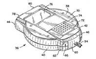
まず、図面を具体的に参照すると、本発明を具現化する複数のセンサ又は試験要素34(図9〜10)が配置されているセンサパック32(図5〜8)が装填されている血中グルコースセンサ分配装置30(図1〜4)が示されている。センサ分配装置30は、上ケース38及び下ケース40を有する外側ハウジング36を含む。上ケース38は下ケース40に対してクラムシェル式に枢転することができ、センサパック32をハウジング36の中に配置することができるようになっている。センサパック32をハウジング36に装填した状態で、ハウジング36の上ケース38に設けられたスライドアクチュエータ42を、上ケース38の後端44に隣接する待機位置(図1〜3)から、上ケース38の前端又は試験端46に隣接する作動位置又は試験位置(図4)に向けて手でスライドさせる。スライドアクチュエータ42はまた、センサ分配装置30をデータ処理又は表示モードに入れるためにも動かすことができる。
【0017】
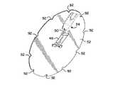
スライドアクチュエータ42の試験位置への移動が、ナイフ刃アセンブリ48(図11に示す)をセンサパック32に対して動かす。ナイフ刃アセンブリ48に設けられたナイフ刃50が、複数のセンサキャビティ54A〜Jの、ナイフ刃50と一直線に並ぶ、センサパック32の台部56中の1個、たとえばキャビティ54Jを覆う、箔52の部分を突き刺す。キャビティ54Jに配置されたセンサ34がナイフ刃50と係合し、その結果、ナイフ刃50が、センサキャビティ54Jを覆う箔52をさらに切断し、センサ34をセンサキャビティ54Jから放出する。
【0018】
センサ34がセンサキャビティ54Jから完全に放出されたのち、センサ34は、センサ分配装置30の試験端46から突出したその試験位置に収まる(図4)。センサ34に設けられた接点58が、ハウジング36の中で、上ケース38に配置された電子回路(図示せず)に連結されている。この回路は、血中グルコース試験手順の間に得られたデータを処理、記憶及び/又は表示するためのマイクロプロセッサなどを含んでもよい。
【0019】
ひとたび血液分析試験が完了したならば、センサ34をハウジング36から解放し、スライドアクチュエータ42を、上ケース38の後端44に隣接するその待機位置に向けて反対方向に手で引き込む。スライドアクチュエータ42がその待機位置に引き込まれる結果、センサパック32の回転が起こり、それにより、センサキャビティ54A〜Jの次の1個がナイフ刃50と一直線に並ぶ位置に配されて、次のセンサキャビティ54I中のセンサ34を次の血中グルコース試験手順に使用することができるようになる。
【0020】
図1〜4に見てとれるように、センサ分配ハウジング36の上ケース38及び下ケース40は、互いに対して枢転されるように適合された、相補的でほぼ丸形の容器である。上ケース38及び下ケース40は、下ケース40の前部又は試験部62に枢転可能に取り付けられたラッチ60により、図1〜4に示すようなそれらの閉形状に維持される。ラッチ60を上向きに枢転させると、ラッチは、上ケース38の前部又は試験端部66の凹み64にパチッとはまり、それにより、上ケース38と下ケース40とを閉形状に固定する。
【0021】
上ケース38は、その外側上壁70に、前部66から後部44に隣接するところまで延びる凹み68を有している。スライドアクチュエータ42がこの凹み68の中に取り付けられて、スライドアクチュエータを前端46に向けて前にスライドさせたり、後端44に向けて引き込んだりできるようになっている。スライドラッチ72がスライドアクチュエータ42に取り付けられ、センサ分配装置30を使用する人がスライドラッチ72及びスライドアクチュエータ42を動かしやすくするための面を提供する複数の盛り上がったこぶ74を有している。
【0022】
スライドラッチ72の移動が、分配装置30が二つの作動モードのいずれに入れられるかを決定する。第一モード又は試験モードでは、スライドラッチ72は、図1、2及び4に示す位置に配される。第二モード又はデータ処理モードでは、スライドラッチ72は、スライドアクチュエータ42に対して横方向にスライドさせたところにある。
【0023】
スライドラッチ72がその試験モード位置にあると、スライドアクチュエータ42を試験端46に向けて動かすにつれ、ナイフ刃アセンブリ48が、箔52及びセンサパック32中のセンサ34の1個に対して動かされる。他方、分配装置30をそのデータ処理モードに入れるためにスライドラッチ72をスライドアクチュエータ42に対して横方向にスライドさせているときには、スライドアクチュエータ42を試験端46に向けて動かしても、ナイフ刃アセンブリ48は動かない。代わりに、スライドアクチュエータ42を上ケース38の前端46に向けて動かすと、分配装置30の状態及び実行中の試験に関するデータ及び他の情報が、上ケース38の後端46の近くで凹み68の中に配されたレンズ76越しに見えるようになる(図4を参照)。装置30がそのデータ処理モード又は表示モードにあるときにレンズ76越しに見える表示は、一部には、後端44に配置された作動ボタン78及び80によって制御される。たとえば、ボタン78及び80を押下すると、表示される試験情報を見たり、入力したりすることができる。
【0024】
分配装置30に使用されるセンサ34は、円形の台部56と、対応する形状の箔52とから形成されているセンサパック32に包装される。センサキャビティ54A〜Jは台部56の凹みとして形成され、センサキャビティ54A〜Jのそれぞれがセンサ34の1個を収容するようになっている。センサキャビティ54Aに関して図6に示すように、センサキャビティ54A〜Jのそれぞれは、センサキャビティ54Aの内端84から外端86まで延びる底支持壁82を有している。この支持壁82は、内端84から外端86まで延びるにつれ、わずかに上向きに傾斜している。支持壁82のこの傾斜の結果として、センサ34がセンサキャビティ54A〜Jから放出されるとき、センサ34がわずかに持ち上げられて、箔52及び台部56の外周沿いの台部56に箔52を固着するヒートシール部分を避ける、又はその上を通過する(pass above)ようになる。
【0025】
各センサキャビティ54A〜Jは、乾燥剤キャビティ88A〜Jの対応する1個と液体導通関係にある。各乾燥剤キャビティ88A〜Jは、台部56に設けられた、センサキャビティ54A〜Jの対応する1個に隣接する小さな凹みから形成されている。センサキャビティ54A〜Jが適切な湿度レベルに維持されることを保証するために、乾燥剤が乾燥剤キャビティ88A〜Jに配置されて、個々のセンサキャビティ54A〜Jに配置されたセンサ34中の試薬物質が使用の前に悪影響を受けることのないようにしている。乾燥剤は、小さな袋もしくは丸いビーズ物質又は乾燥剤キャビティ88A〜Jに容易に配置することができる他いかなる形態であってもよい。乾燥剤キャビティ88A〜Jのそれぞれに配置されるそのような乾燥剤の量は、センサキャビティ54A〜Jを乾燥状態に維持するのに要する量に依存するであろう。用いることができる乾燥剤の一つのタイプは、商品名NATRASORB の下で販売され、粉末、ペレット及びビーズの形態で利用することができる。
【0026】
切欠き90が台部56の外周縁に形成されている。箔52が台部56にシールされると、箔52の外周縁沿いの切欠き92が切欠き90と整合し、それにより、センサパック32の外周縁に、一体化した一連の切欠きを形成する。切欠き90及び92によって形成される各切欠きは、台部56のセンサキャビティ54A〜Jの1個と関連して、センサパック32を分配装置30に取り付けたとき、センサパック32を回転させると、センサキャビティ54A〜Jの各1個がナイフ刃アセンブリ48のナイフ刃50と順次に適切に整合して、センサキャビティ54A〜Jの中のセンサ34の個々をセンサキャビティ54A〜Jから放出することができるようになる。
【0027】
箔52は、台部56の上面を覆うためのもので、箔52の外周縁全体を台部56の外周縁に対してヒートシールすることにより、台部56に取り付けられる。箔52はまた、個々のセンサ34が乾燥状態に維持され、互いに隔離されるよう、センサ保持キャビティ54A〜Jと乾燥剤キャビティ88A〜Jとの各組の全周囲でもヒートシールされて、センサ保持キャビティ54A〜J及び乾燥剤キャビティ88A〜Jをシールしている。その結果、センサキャビティ54A〜Jの1個の開封が他のセンサキャビティ54A〜Jのいずれかの乾燥状態に影響することはない。箔52は、センサキャビティ54A〜J及び乾燥剤キャビティ88A〜Jを十分にシールすると同時に、センサ34がセンサキャビティ54A〜Jから押し出されるときにナイフ刃50によって本当に切断され、センサ34によって突き刺される材料を提供するいかなる材料からなるものでもよい。箔52に使用することができる一つのタイプの箔は、Alusuisse Flexible Packaging社によって販売されているAL−191−01箔である。
【0028】
図8に示すように、センサパック32の台部56は、その下面の、センサキャビティ54A〜Jよりも内側にラベル区域94を含む。導電性ラベル96がこのラベル区域94に配置され、センサパック32をセンサ分配装置30に装填しているとき、感知することができる較正及び生成の情報を提供する。
【0029】
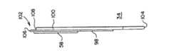
センサパック32は、10個のセンサ34をセンサキャビティ54A〜Jのそれぞれに1個ずつ収容するためのものである。図9及び10に示すように、各センサ34は、ほぼ平坦な矩形であり、はめ合いプラスチック片、すなわち蓋98及び台100から形成され、前端又は試験端102から後端又は放出端104まで延びている。各センサ34には、センサ34の前端又は試験端102からセンサ34のはめ合い部片98及び100の間に配置された生感知性又は試薬物質に延びる毛管路が設けられている。センサ34の試験端102が流体(たとえば、指を何かで刺したのち指先に溜る血)の中に配置されると、その流体の一部が毛管作用によって毛管路に引き込まれて、試験するのに十分な量の流体がセンサ34に引き込まれるようになる。そして、この流体はセンサ34中の試薬物質と化学反応を起こして、試験される血液中のグルコース濃度を示す電気信号が接点58に供給され、ひいては、感知装置30中の回路に供給される。
【0030】
以下さらに詳細に論じるように、蓋98の前縁又は先頭縁106は、台100の前縁又は尾縁108に対して縦方向にずらされ、前縁106及び108は、センサ34がナイフ刃50によってセンサキャビティ54Jから押し出されるとき、センサ34の前端102が、箔52の破片を剥離させることなく、たとえばセンサキャビティ54Jを覆う箔52の切断されていない部分を突き刺すような特定の角形状を有している。センサ34の後端104は、ナイフ刃50がセンサ34をセンサキャビティ54Jから放出するときにナイフ刃50がそこに配置される小さな切欠き110を含む。切欠き110は、ナイフ刃50がセンサ34と接触するための目標区域を提供し、ひとたびナイフ刃50が切欠き110と接触すると、ナイフ刃50はセンサ34の中心に来る。センサ34の蓋98に設けられた接点58は、センサ34を、図4に示すその試験位置に動かしたとき、センサ分配装置30の内部の回路と連結される。その結果、試験中にセンサ34で生成された情報を記憶したり、解析したりすることができる。
【0031】
上記に示したように、蓋98の前試験縁又は先頭縁106及び台100の前試験縁又は尾縁108の特定の形状ならびにそれらの互いに対する配置が、箔52から破片を剥離させることなく、センサ34をセンサキャビティ54A〜Jから放出するのに有意である。具体的には、図9に示すセンサ34は、後端104から前端102まで延びる縦軸112と、縦軸112に対して垂直な方向に、側縁116から側縁118まで延びる横軸114とを有している。蓋98の前試験縁106は、蓋98の前試験縁106が、蓋98の前試験縁106が、センサキャビティ54Jを覆う箔52を切断するための離れた別個の切れ刃を実質的に形成するのに十分なほど、台100の前試験縁108よりも縦軸112の方向に前に出るよう、センサ34の台100の前試験縁108よりも前に張り出している。センサ34の一つの実施態様では、前縁106及び108は、前縁106と前縁108とが互いに隣接するよう、互いに対して少なくとも1000分の10インチずらされているが、また、センサ34の縦軸112の方向にも互いに対してわずかにずらされている。
【0032】
台100及び蓋98の両方の側縁116の前部120は、縦軸112に対して約25°(図9の角度A)で斜めにカットされている。蓋98及び台100それぞれの前縁106及び108は、センサ34の横軸114に対して傾いている。図9からわかるように、台100の前縁108は、斜めにカットされた前部120から、横軸114に対して約10°(図9の角度B)で、センサ34の残りの全幅にかけて側縁118まで延びている。蓋98の前縁106もまた、センサ34の横軸114に対して斜めであるが、これは、二つの別個の角部分を有している。前蓋縁106の主要部122は、センサ34の横軸114に対して約15°(図9の角度C)で、前部120からセンサ34の幅の有意部分にかけて側縁118まで延びている。蓋98の前縁106の残り部分124は、主要部122から、センサ34の横軸114に対してより大きな約25°(図9の角度D)で延びている。その結果、残りの部分124は、比較的尖った先端126を側縁118に形成している。
【0033】
尖端126は、センサ34がセンサキャビティ54Jから放出されるとき、尖端126が、はじめは最小限の力で、センサ34が配置されているセンサキャビティ54Jを覆う箔52を突き刺すよう、蓋の縁106にナイフ状部分を提供する。センサ34がセンサキャビティ54Jから放出され続けると、斜めの縁部124が箔52を切り裂き続ける。場合によっては、蓋の縁106が台の縁108よりも前にあるとしても、箔52の小片又は破片部が形成し始める。しかし、箔52のこの破片部は、箔52の残り部分から完全にちぎれることはない。それどころか、センサ34が放出される間、角度のより小さい部分122が箔52と係合し始めると、破片部は箔52の上に反り返る。箔の破片が箔52の上に反り返った状態では、破片は、箔52の残り部分から完全に離れることはなく、センサ34を用いて実施される試験に悪影響を及ぼさない位置に残る。
【0034】
センサ34の台100に対する蓋98の張り出しと、台100の前縁108の特定の角と、蓋98の前縁106の部分122及び124の斜角とが、センサ34が放出されるとき、センサ34が、箔52の破片を箔52から剥離させることなく、センサキャビティ54Jを覆う箔52を突き刺すことを可能にする。それにもかかわらず、前縁106及び108の斜角ならびに前縁106と前縁108との空間的関係が、許容しうる最小限の力で、センサ34をキャビティ54Jから放出することを可能にする。
【0035】
例示した実施態様の詳細を参照しながら本発明を説明したが、そのような詳細は、請求の範囲に定める本発明の範囲を限定しようとするものではない。たとえば、センサ34は、装置30とともに、血中グルコース以外の流体を試験するために使用することもできる。実際、センサ34は、試薬物質によって分析することができるものならば、いかなるタイプの化学物質流体の分析にも使用することができる。
【図面の簡単な説明】
【図1】血中グルコースセンサ分配装置の斜視図である。
【図2】図1の血中グルコースセンサ分配装置の平面図である。
【図3】図1の血中グルコースセンサ分配装置の底面図である。
【図4】図1の血中グルコースセンサ分配装置を、試験位置にある状態で示す斜視図である。
【図5】図1の血中グルコースセンサ分配装置に使用されるセンサパックを、センサパックの箔部をセンサパックの台部から離した状態で、各センサキャビティに配置されたセンサとともに示す分解斜視図である。
【図6】図5のセンサパックの台部の斜視図である。
【図7】図5のセンサパックの台部の側面図である。
【図8】図5のセンサパックの台部の底面図である。
【図9】本発明を具現化するセンサの平面図である。
【図10】図9のセンサの側面図である。
【図11】図5のセンサパック中のセンサの1個とナイフ刃との係合を示す図である。
【符号の説明】
30 センサ分配装置
32 センサパック
34 センサ
48 ナイフ刃アセンブリ
54A〜J センサキャビティ
88A〜J 乾燥剤キャビティ
98 蓋
100 台
104 後端
106、108 前縁[0001]
BACKGROUND OF THE INVENTION
The present invention relates generally to fluid monitoring sensors, and more particularly to a sensor pack used to analyze blood glucose or other analytes contained in blood in a sensor pack loaded in a dispensing device. It relates to a new and improved sensor configured to prevent separation of sensor pack material debris that may interfere with correct operation of the dispensing device when released from the cavity.
[0002]
[Prior art]
People with various symptoms of diabetes must routinely test their blood to determine blood glucose levels. The results of such tests can be used to determine what, if any, insulin or other drug needs to be administered. One type of blood glucose test system uses a sensor to test a blood sample.
[0003]
Such sensors may be substantially flat rectangles and are formed from two mating plastic pieces, a pedestal and a lid. The sensor has a front end or a test end and a rear end. The sensor contains a biosensing or reagent material that reacts with blood glucose. The test end of the sensor is placed in the fluid to be tested, for example, blood that accumulates on the surface of the finger after the finger has been stabbed with something. A sufficient amount of fluid to be tested is drawn by capillary action into a capillary channel that extends between the mating pieces of the sensor from the test end to the reagent material. The fluid then chemically reacts with the reagent substance in the sensor, so that an electrical signal indicating the glucose concentration in the blood to be tested is supplied to a contact located outside the sensor.
[0004]
In order to couple the electrical signal generated at the sensor contacts to the monitoring instrument, the sensor must be inserted into the sensor holder prior to placing the test end of the sensor into the fluid being tested. The holder has a corresponding mating contact that is coupled to a contact on the sensor when the sensor is inserted into the holder. As a result, the holder serves as an interface between the sensor and a monitoring device that stores and / or analyzes the test results.
[0005]
Prior to use, the sensor must be maintained at an appropriate humidity level to ensure the integrity of the reagent material in the sensor. The sensors can be packaged one by one in a tear-away package so that they can be maintained at an appropriate humidity level. For example, a blister type packaging method may be used. In this regard, the package can include a desiccant to maintain an appropriate humidity or dry level in the package. In order to use individual sensors to test blood glucose, the package must be opened by tearing off the seal. Alternatively, some packages require the user to apply a force on one side of the package and cause the sensor to rupture or tear the foil on the other side. As can be appreciated, opening these packages can be difficult. In addition, once the package has been opened, the user must place the sensor in the sensor holder and make sure that the sensor is not damaged or contaminated when used to test a blood sample. Must be confirmed.
[0006]
A sensor distribution device has been developed for individually distributing sensors to sensing positions from among sensor packs loaded in the sensor distribution device. One such type of sensor pack includes a generally circular pedestal having a sensor holding cavity or recess formed therein. Each sensor holding cavity receives one sensor and is in circulation with a corresponding desiccant cavity in which the desiccant is disposed. Desiccant is placed in the cavity to ensure that the corresponding sensor cavity is maintained at the appropriate humidity or dry level so that the reagent material in the sensor is not adversely affected before the sensor is used. Is done. The foil is heat sealed to the pedestal over the entire outer periphery of the pedestal and the entire perimeter of each set of sensor holding and desiccant cavities to seal the sensor holding and desiccant cavities. As a result, the individual sensors are kept dry and, in addition, they are isolated from one another so that opening of one sensor cavity does not adversely affect the dryness of the other sensor cavities.
[0007]
The circular sensor pack can be loaded into a sensor dispensing device having a feed mechanism. When the feed mechanism is activated and moved forward toward the test position of the device, one of the sensors in the sensor pack is released from the sensor pack and placed in the sensing position. In this regard, when the feed mechanism is moved forward, the drive with the knife blade attached moves toward one of the sensor cavities in the sensor pack that is in line with the knife blade. The knife blade pierces the foil covering the sensor cavity and engages the rear end of the sensor disposed in the cavity. As the drive continues to be pushed forward, the knife blade further tears the foil covering the sensor cavity, releases the sensor out of the sensor cavity (concept including extrusion and ejection), and the sensor from the outer foil covering the sensor cavity Break through the slanted leading edge. When the sensor is pushed out of the sensor cavity, it moves along the inclined support wall of the sensor cavity platform, so that even when advanced by a knife blade, the heat seal that secures the foil to the platform of the sensor pack. No need to be pushed in. The force required to carry the sensor through the foil is determined in part by the specific shape of the front of the sensor.
[0008]
While the test end of the sensor protrudes from the test end of the device, the sensor is guided to its test position. When in the test position, the contacts in the device are mated with the corresponding contacts on the sensor. The sensor dispensing device includes a microprocessor or other data processing circuit electrically coupled to the contacts of the device so that data obtained from the sensor can be processed when the sensor is inserted into the blood being tested. There may be. The processed data can then be displayed on the screen of the device or stored for use in other analytical instruments.
[0009]
After analyzing the fluid, a feed mechanism can be used to release the used sensor from the test end of the dispensing device. Subsequent retracting of the feed mechanism to its standby position results in rotation of the sensor pack, and when another sensor cavity is aligned with the knife blade of the drive mechanism and begins a series of operations again, One sensor can be released from the sensor pack.
[0010]
As indicated above, the sensor consists of a mating plastic lid and base with a reagent material between them. The test end shape of both the sensor lid and pedestal parts must be such that the sensor can penetrate the thin foil covering the sensor cavity of the sensor pack with minimal force. However, the edge of the test end of the lid and pedestal causes breakage of the foil piece (the piece of foil that peels off the foil covering the sensor cavity) when the sensor is released from the sensor cavity through the foil. There is a fear. Stripped foil debris can block the capillary passage and prevent the fluid being tested from flowing into the sensor, or short circuit the device or sensor contact, thereby rendering the device inoperable.
[0011]
The formation of such foil fragments tends to be caused by the shape and spatial relationship of the mating plastic pieces (ie, lid and platform) at the test end of the sensor. When the lid and the base are not sufficiently displaced in the vertical direction relative to each other (that is, the direction from the rear end to the front end of the sensor), the base and the lid do not cut the foil, but rather scissors Two cutting edges that can be cut by are formed. This scissor-like action tends to produce foil strips or debris from the foil covering the sensor cavity. The angle of the lid and / or platform relative to the horizontal axis of the sensor can also contribute to the formation of foil fragments. For example, debris may break from the foil when the lid and pedestal test ends are tilted at a continuous angle (usually at an obtuse angle) relative to the horizontal axis of the sensor. Taking into account the fact that the foil debris peeled off the foil covering the sensor cavity can adversely affect the operation of the sensor device, it ensures that the foil debris does not delaminate when the sensor is released from the sensor cavity It would be advantageous.
[0012]
[Problems to be solved by the invention]
Accordingly, an object of the present invention is a novel that is intended to be released from a sensor pack loaded into a sensor dispensing device used to analyze blood glucose or other analytes contained in blood. It is to provide an improved sensor. Another object of the present invention is to provide a new and improved blood glucose sensor having a front test end shaped to facilitate release of the sensor from the sensor pack; plastic mating base piece and lid A new and improved blood glucose sensor formed from a strip, the front test end of which is shaped to minimize the occurrence of foil debris when the sensor is released from the sensor cavity in the sensor pack A blood glucose sensor formed from a plastic mating base piece and a lid piece, the front edge of the base and lid being arranged relative to each other, the sensor being a sensor The sensor can be released from the sensor cavity with minimal force while minimizing the occurrence of foil debris when released from the sensor cavity in the pack And to provide a blood glucose sensor, which is a new and improved with Unisuru certain oblique angle.
[0013]
[Means for Solving the Problems]
In accordance with these and many other objects of the present invention, the present invention is embodied in a sensor adapted to be stored in a sensor cavity of a sensor pack used in a sensor dispensing device. The sensor is a substantially flat rectangle, formed from two mating pieces of plastic material, one forming the sensor platform and the other forming the sensor lid. The sensor has a vertical axis extending from the front test end to the rear discharge end, and the horizontal axis extends between the side edges of the sensor in a direction perpendicular to the vertical axis. A biosensory or reagent substance that reacts with blood glucose is placed in the sensor between the platform and the lid. The test end of the sensor is placed in the fluid to be tested so that a sufficient amount of fluid is drawn by capillary action into the capillary passage that extends between the mating pieces of the sensor from the test end to the reagent material. It is supposed to be. The fluid undergoes a chemical reaction with the reagent substance in the sensor, so that an electrical signal indicative of the glucose concentration in the blood being tested is supplied to a contact provided on the sensor.
[0014]
The rear ejector end of the sensor has a notch that engages the knife blade of the sensor dispensing device when the sensor is ejected from the sensor cavity of the sensor pack. The front test edge of the lid is more than the front test edge of the sensor platform so that the front test edge of the lid is sufficiently longitudinally forward of the front test edge of the platform to be sufficient to have a single cutting edge. Projecting forward. The side edges of the sensor adjacent to the front edge of the platform and lid are cut obliquely at about 25 °. The leading edges of both the base and the lid are inclined with respect to the horizontal axis of the sensor. The front edge of the pedestal extends at an angle of about 10 ° with respect to the horizontal axis from the diagonally cut side to the entire remaining width of the sensor. The front edge of the lid is also oblique with respect to the horizontal axis of the sensor, but the front edge has two different corners. The first main portion of the front lid edge extends at approximately 15 ° with respect to the horizontal axis of the sensor from the diagonally cut side to a significant portion of the sensor width. The other part of the front edge of the lid extends at an angle of about 25 ° with respect to the horizontal axis of the sensor so that the sensor is ejected from the cavity from the diagonally cut side to the opposite side edge. A relatively pointed tip is formed that pierces the foil covering the sensor cavity where the sensor is located.
[0015]
The overhang of the lid over the sensor pedestal and the specific angle of the sensor lid and the leading edge of the pedestal allows the sensor to break through the foil covering the sensor cavity from which the sensor is released with an acceptable force. enable. On the other hand, the specific shape of the overhang of the lid over the base and the bevel of the front edge of the base and lid is such that when the sensor is ejected from the sensor cavity in which the sensor is housed, Guarantee that it will not peel from.
[0016]
DETAILED DESCRIPTION OF THE INVENTION
First, with specific reference to the drawings, blood is loaded with a sensor pack 32 (FIGS. 5-8) on which a plurality of sensors or test elements 34 (FIGS. 9-10) embodying the present invention are arranged. A glucose sensor dispensing device 30 (FIGS. 1-4) is shown. The
[0017]
Movement of the
[0018]
After the
[0019]
Once the blood analysis test is complete, the
[0020]
As can be seen in FIGS. 1-4, the
[0021]
The
[0022]
The movement of the
[0023]
When the
[0024]
The
[0025]
Each
[0026]
A
[0027]
The
[0028]
As shown in FIG. 8, the
[0029]
The
[0030]
As discussed in more detail below, the leading or
[0031]
As indicated above, the particular shape of the front test edge or leading
[0032]
The
[0033]
The
[0034]
The overhang of the
[0035]
Although the invention has been described with reference to details of the illustrated embodiments, such details are not intended to limit the scope of the invention as defined in the claims. For example,
[Brief description of the drawings]
FIG. 1 is a perspective view of a blood glucose sensor dispensing device.
2 is a plan view of the blood glucose sensor dispensing device of FIG. 1. FIG.
3 is a bottom view of the blood glucose sensor dispensing device of FIG. 1. FIG.
4 is a perspective view showing the blood glucose sensor dispensing device of FIG. 1 in a state of being in a test position. FIG.
5 is an exploded perspective view showing the sensor pack used in the blood glucose sensor dispensing apparatus of FIG. 1 together with the sensors disposed in the sensor cavities in a state where the foil portion of the sensor pack is separated from the base portion of the sensor pack. FIG.
6 is a perspective view of a base portion of the sensor pack of FIG. 5. FIG.
7 is a side view of a base portion of the sensor pack of FIG. 5. FIG.
8 is a bottom view of the base portion of the sensor pack of FIG. 5. FIG.
FIG. 9 is a plan view of a sensor embodying the present invention.
10 is a side view of the sensor of FIG. 9. FIG.
11 is a view showing the engagement between one of the sensors in the sensor pack of FIG. 5 and a knife blade. FIG.
[Explanation of symbols]
30 Sensor distributor
32 Sensor pack
34 sensors
48 Knife Blade Assembly
54A-J Sensor cavity
88A-J Desiccant cavity
98 lid
100 units
104 Rear end
106,108 leading edge
Claims (17)
Translated fromJapanese該縦軸に沿って延び、該保護被覆を切断するための前切断縁を有する該要素の第一の部分と、
該縦軸に沿って延び、後縁を有する該要素の第二の部分とを含み、
該要素が該キャビティから放出されつつあるとき、該前切断縁が該保護被覆を突き刺すことを特徴とする試験要素。A package containing the test element, the package forms a sealed cavity by a protective coating, the test elementisaccommodated in thedischarge(eject)capable within the cavityfrom thecavity,the element from the rear end of the element Having a longitudinal axis extending to the front end of the test element,
A first portion of the element extending along the longitudinal axis and havinga frontcutting edgefor cutting the protective coating ;
A second portion of the element extending along the longitudinal axis and having a trailing edge;
A test element characterized in thatthe front cutting edge pierces theprotective coating when the element is being ejected from the cavity .
該要素の該縦軸に沿って延び、前台縁を有する台部と、
該要素の該縦軸に沿って延び、前蓋切断縁を有する、該台部とはまり合う蓋部とを含み、
該前蓋切断縁及び該前台縁が、該横軸及び互いに対して傾斜していて、それにより、該前蓋切断縁が、該要素が該キャビティから放出されつつあるとき、該保護被覆の破片を該保護被覆から分離させることなく該保護被覆を切断する突端を有することを特徴とする試験要素。A packaged test element, wherein the package forms a cavity sealed by a protective coating, the test element beinghoused in the cavity so as to beejectablefrom the cavity and fromthe rear end of the test element A longitudinal axis extending to the front end of the test element and a transverse axis extending between opposing side edges of the element in a direction perpendicular to the longitudinal axis, the test element comprising:
A platform extending along the longitudinal axis of the element and having a front rim;
A mating lid portion extending along the longitudinal axis of the element and having a front lidcutting edge;
Theprotective cover debris when the front lidcutting edge and the front base edge are inclined relative to the transverse axis and each other so that the front lidcutting edge is being ejected from the cavity A test element having a tip for cutting theprotective coating without separating theprotective coating from theprotective coating .
該後端から該前端に延び、該保護被覆を切断するために該センサの該前端に沿って第一の前切断縁を有する、該センサの第一の表面と、
該後端から該前端に隣接するところまで延び、該センサの該前端に隣接した第二の前縁を有する、該センサの第二の表面とを含み、
その結果、該第一の前切断縁が、該縦軸に沿って、該第二の前縁に隣接し、該第二の前縁よりも前にあるところまで延び、該第一の前切断縁が該第二の前縁よりも前に張り出し、該第二の前縁が、該横軸に対して約10°の角度で延び、該第一の前切断縁が、該横軸に対して約15°の角度で延びる第一の縁部と、該横軸に対して約25°の角度で延びる第二の縁部とを有することを特徴とする流体試験センサ。A packaged fluid test sensor, wherein the packageforms a cavity sealed by aprotective coating, and the test sensor ishoused in the cavity so as to beejectablefrom the cavity, fromthe rear end of the sensor A vertical axis extending to the front end of the sensor and a horizontal axis extending between opposing side edges of the sensor in a direction perpendicular to the vertical axis, the sensor comprising:
A first surface of the sensor extending from the rear end to the front end and having a first frontcutting edge along the front end of the sensorto cut the protective coating ;
A second surface of the sensor extending from the rear end to adjacent the front end and having a second front edge adjacent to the front end of the sensor;
As a result, prior tocutting edge of the first is, along the said longitudinal axis, adjacent the leading edge of the second, extended far in front than the front edge of the second, said firstpre-cut An edge projects ahead of the second leading edge, the second leading edge extends at an angle of about 10 ° relative to the transverse axis, and the first leadingcutting edge is oriented relative to the transverse axis A fluid test sensor having a first edge extending at an angle of about 15 ° and a second edge extending at an angle of about 25 ° relative to the transverse axis.
Applications Claiming Priority (2)
| Application Number | Priority Date | Filing Date | Title |
|---|---|---|---|
| US08/659360 | 1996-06-06 | ||
| US08/659,360US5660791A (en) | 1996-06-06 | 1996-06-06 | Fluid testing sensor for use in dispensing instrument |
Publications (3)
| Publication Number | Publication Date |
|---|---|
| JPH1062424A JPH1062424A (en) | 1998-03-06 |
| JPH1062424A5 JPH1062424A5 (en) | 2005-04-14 |
| JP4047948B2true JP4047948B2 (en) | 2008-02-13 |
Family
ID=24645086
Family Applications (1)
| Application Number | Title | Priority Date | Filing Date |
|---|---|---|---|
| JP14737597AExpired - Fee RelatedJP4047948B2 (en) | 1996-06-06 | 1997-06-05 | Fluid test sensor for use in a dispensing device |
Country Status (8)
| Country | Link |
|---|---|
| US (1) | US5660791A (en) |
| EP (1) | EP0811843B1 (en) |
| JP (1) | JP4047948B2 (en) |
| AT (1) | ATE527535T1 (en) |
| AU (1) | AU709487B2 (en) |
| CA (1) | CA2198946C (en) |
| DK (1) | DK0811843T3 (en) |
| ES (1) | ES2373214T3 (en) |
Families Citing this family (145)
| Publication number | Priority date | Publication date | Assignee | Title |
|---|---|---|---|---|
| NZ524206A (en)* | 1997-12-04 | 2004-05-28 | Roche Diagnostics Corp | Instrument for determining the concentration of a medically significant component of a sample |
| US6391005B1 (en) | 1998-03-30 | 2002-05-21 | Agilent Technologies, Inc. | Apparatus and method for penetration with shaft having a sensor for sensing penetration depth |
| US7416699B2 (en) | 1998-08-14 | 2008-08-26 | The Board Of Trustees Of The Leland Stanford Junior University | Carbon nanotube devices |
| US20050037505A1 (en)* | 2000-05-11 | 2005-02-17 | James Samsoondar | Spectroscopic method and apparatus for analyte measurement |
| US7138089B2 (en)* | 2000-07-20 | 2006-11-21 | Hypoguard Limited | Test device for analyzing blood glucose or other analytes in bodily fluids |
| US6827899B2 (en)* | 2000-08-30 | 2004-12-07 | Hypoguard Limited | Test device |
| US8641644B2 (en) | 2000-11-21 | 2014-02-04 | Sanofi-Aventis Deutschland Gmbh | Blood testing apparatus having a rotatable cartridge with multiple lancing elements and testing means |
| US6752817B2 (en)* | 2001-03-26 | 2004-06-22 | Bayer Corporation | Split pressure ring for lancing device and method of operation |
| US6988996B2 (en) | 2001-06-08 | 2006-01-24 | Roche Diagnostics Operatons, Inc. | Test media cassette for bodily fluid testing device |
| US9427532B2 (en) | 2001-06-12 | 2016-08-30 | Sanofi-Aventis Deutschland Gmbh | Tissue penetration device |
| US7041068B2 (en) | 2001-06-12 | 2006-05-09 | Pelikan Technologies, Inc. | Sampling module device and method |
| EP1395185B1 (en) | 2001-06-12 | 2010-10-27 | Pelikan Technologies Inc. | Electric lancet actuator |
| US7981056B2 (en) | 2002-04-19 | 2011-07-19 | Pelikan Technologies, Inc. | Methods and apparatus for lancet actuation |
| US9795747B2 (en) | 2010-06-02 | 2017-10-24 | Sanofi-Aventis Deutschland Gmbh | Methods and apparatus for lancet actuation |
| US8337419B2 (en) | 2002-04-19 | 2012-12-25 | Sanofi-Aventis Deutschland Gmbh | Tissue penetration device |
| JP4209767B2 (en) | 2001-06-12 | 2009-01-14 | ペリカン テクノロジーズ インコーポレイテッド | Self-optimized cutting instrument with adaptive means for temporary changes in skin properties |
| US7344507B2 (en) | 2002-04-19 | 2008-03-18 | Pelikan Technologies, Inc. | Method and apparatus for lancet actuation |
| US7749174B2 (en) | 2001-06-12 | 2010-07-06 | Pelikan Technologies, Inc. | Method and apparatus for lancet launching device intergrated onto a blood-sampling cartridge |
| US9226699B2 (en) | 2002-04-19 | 2016-01-05 | Sanofi-Aventis Deutschland Gmbh | Body fluid sampling module with a continuous compression tissue interface surface |
| US7611899B2 (en)* | 2001-08-13 | 2009-11-03 | Bayer Healthcare Llc | Sensor release for a sensor dispensing instrument |
| US7323141B2 (en)* | 2001-08-13 | 2008-01-29 | Bayer Healthcare Llc | Button layout for a testing instrument |
| US7723113B2 (en)* | 2001-08-20 | 2010-05-25 | Bayer Healthcare Llc | Packaging system for test sensors |
| US6997343B2 (en)* | 2001-11-14 | 2006-02-14 | Hypoguard Limited | Sensor dispensing device |
| US20030111357A1 (en)* | 2001-12-13 | 2003-06-19 | Black Murdo M. | Test meter calibration |
| US7004928B2 (en) | 2002-02-08 | 2006-02-28 | Rosedale Medical, Inc. | Autonomous, ambulatory analyte monitor or drug delivery device |
| DE20213607U1 (en) | 2002-02-21 | 2003-07-03 | Paul Hartmann AG, 89522 Heidenheim | Blood analyzer for the determination of an analyte |
| DE10245721A1 (en)* | 2002-02-21 | 2003-12-11 | Hartmann Paul Ag | Blood analyzer device comprises needles, test media, analyzer and display, and has carrier turned with respect to main body, to position needle and test media |
| US20030169426A1 (en)* | 2002-03-08 | 2003-09-11 | Peterson Timothy A. | Test member orientation |
| CA2419905C (en) | 2002-03-18 | 2016-01-05 | Bayer Healthcare, Llc | Storage cartridge for biosensors |
| US6881578B2 (en)* | 2002-04-02 | 2005-04-19 | Lifescan, Inc. | Analyte concentration determination meters and methods of using the same |
| US7976476B2 (en) | 2002-04-19 | 2011-07-12 | Pelikan Technologies, Inc. | Device and method for variable speed lancet |
| US8784335B2 (en) | 2002-04-19 | 2014-07-22 | Sanofi-Aventis Deutschland Gmbh | Body fluid sampling device with a capacitive sensor |
| US7909778B2 (en) | 2002-04-19 | 2011-03-22 | Pelikan Technologies, Inc. | Method and apparatus for penetrating tissue |
| US9795334B2 (en) | 2002-04-19 | 2017-10-24 | Sanofi-Aventis Deutschland Gmbh | Method and apparatus for penetrating tissue |
| US7229458B2 (en) | 2002-04-19 | 2007-06-12 | Pelikan Technologies, Inc. | Method and apparatus for penetrating tissue |
| US8372016B2 (en) | 2002-04-19 | 2013-02-12 | Sanofi-Aventis Deutschland Gmbh | Method and apparatus for body fluid sampling and analyte sensing |
| US8267870B2 (en) | 2002-04-19 | 2012-09-18 | Sanofi-Aventis Deutschland Gmbh | Method and apparatus for body fluid sampling with hybrid actuation |
| US7892183B2 (en) | 2002-04-19 | 2011-02-22 | Pelikan Technologies, Inc. | Method and apparatus for body fluid sampling and analyte sensing |
| US7491178B2 (en) | 2002-04-19 | 2009-02-17 | Pelikan Technologies, Inc. | Method and apparatus for penetrating tissue |
| US9314194B2 (en) | 2002-04-19 | 2016-04-19 | Sanofi-Aventis Deutschland Gmbh | Tissue penetration device |
| US8579831B2 (en) | 2002-04-19 | 2013-11-12 | Sanofi-Aventis Deutschland Gmbh | Method and apparatus for penetrating tissue |
| US7674232B2 (en) | 2002-04-19 | 2010-03-09 | Pelikan Technologies, Inc. | Method and apparatus for penetrating tissue |
| US9248267B2 (en) | 2002-04-19 | 2016-02-02 | Sanofi-Aventis Deustchland Gmbh | Tissue penetration device |
| US7331931B2 (en) | 2002-04-19 | 2008-02-19 | Pelikan Technologies, Inc. | Method and apparatus for penetrating tissue |
| US8360992B2 (en) | 2002-04-19 | 2013-01-29 | Sanofi-Aventis Deutschland Gmbh | Method and apparatus for penetrating tissue |
| US7547287B2 (en) | 2002-04-19 | 2009-06-16 | Pelikan Technologies, Inc. | Method and apparatus for penetrating tissue |
| US7708701B2 (en) | 2002-04-19 | 2010-05-04 | Pelikan Technologies, Inc. | Method and apparatus for a multi-use body fluid sampling device |
| US7297122B2 (en) | 2002-04-19 | 2007-11-20 | Pelikan Technologies, Inc. | Method and apparatus for penetrating tissue |
| US8702624B2 (en) | 2006-09-29 | 2014-04-22 | Sanofi-Aventis Deutschland Gmbh | Analyte measurement device with a single shot actuator |
| US7901362B2 (en) | 2002-04-19 | 2011-03-08 | Pelikan Technologies, Inc. | Method and apparatus for penetrating tissue |
| US7232451B2 (en) | 2002-04-19 | 2007-06-19 | Pelikan Technologies, Inc. | Method and apparatus for penetrating tissue |
| US8221334B2 (en) | 2002-04-19 | 2012-07-17 | Sanofi-Aventis Deutschland Gmbh | Method and apparatus for penetrating tissue |
| US7343188B2 (en)* | 2002-05-09 | 2008-03-11 | Lifescan, Inc. | Devices and methods for accessing and analyzing physiological fluid |
| US20030211619A1 (en)* | 2002-05-09 | 2003-11-13 | Lorin Olson | Continuous strip of fluid sampling and testing devices and methods of making, packaging and using the same |
| CN100498320C (en)* | 2002-05-23 | 2009-06-10 | 爱科来株式会社 | Analytical tool, analytical device, analytical tool set, and method for manufacturing analytical tool set |
| US7250095B2 (en)* | 2002-07-11 | 2007-07-31 | Hypoguard Limited | Enzyme electrodes and method of manufacture |
| AU2003234944A1 (en)* | 2002-08-27 | 2004-03-18 | Bayer Healthcare, Llc | Methods of Determining Glucose Concentration in Whole Blood Samples |
| IES20020794A2 (en)* | 2002-10-04 | 2003-02-19 | Minroc Techn Promotions Ltd | A down-the-hole hammer |
| US7572237B2 (en) | 2002-11-06 | 2009-08-11 | Abbott Diabetes Care Inc. | Automatic biological analyte testing meter with integrated lancing device and methods of use |
| US8574895B2 (en) | 2002-12-30 | 2013-11-05 | Sanofi-Aventis Deutschland Gmbh | Method and apparatus using optical techniques to measure analyte levels |
| US7264139B2 (en)* | 2003-01-14 | 2007-09-04 | Hypoguard Limited | Sensor dispensing device |
| US7132041B2 (en)* | 2003-02-11 | 2006-11-07 | Bayer Healthcare Llc | Methods of determining the concentration of an analyte in a fluid test sample |
| US7052652B2 (en) | 2003-03-24 | 2006-05-30 | Rosedale Medical, Inc. | Analyte concentration detection devices and methods |
| DE602004028463D1 (en) | 2003-05-30 | 2010-09-16 | Pelikan Technologies Inc | METHOD AND DEVICE FOR INJECTING LIQUID |
| US7850621B2 (en) | 2003-06-06 | 2010-12-14 | Pelikan Technologies, Inc. | Method and apparatus for body fluid sampling and analyte sensing |
| WO2006001797A1 (en) | 2004-06-14 | 2006-01-05 | Pelikan Technologies, Inc. | Low pain penetrating |
| US7364699B2 (en)* | 2003-06-18 | 2008-04-29 | Bayer Healthcare Llc | Containers for reading and handling diagnostic reagents and methods of using the same |
| US20040267299A1 (en)* | 2003-06-30 | 2004-12-30 | Kuriger Rex J. | Lancing devices and methods of using the same |
| WO2005018425A2 (en) | 2003-08-20 | 2005-03-03 | Facet Technologies, Llc | Blood sampling device |
| WO2005018454A2 (en) | 2003-08-20 | 2005-03-03 | Facet Technologies, Llc | Multi-lancet device with sterility cap repositioning mechanism |
| US8282576B2 (en) | 2003-09-29 | 2012-10-09 | Sanofi-Aventis Deutschland Gmbh | Method and apparatus for an improved sample capture device |
| EP1680014A4 (en) | 2003-10-14 | 2009-01-21 | Pelikan Technologies Inc | METHOD AND DEVICE FOR A VARIABLE USER INTERFACE |
| US8007656B2 (en)* | 2003-10-24 | 2011-08-30 | Bayer Healthcare Llc | Enzymatic electrochemical biosensor |
| US8221332B2 (en) | 2003-11-12 | 2012-07-17 | Facet Technologies, Llc | Multi-lancet cartridge and lancing device |
| US8668656B2 (en) | 2003-12-31 | 2014-03-11 | Sanofi-Aventis Deutschland Gmbh | Method and apparatus for improving fluidic flow and sample capture |
| US7822454B1 (en) | 2005-01-03 | 2010-10-26 | Pelikan Technologies, Inc. | Fluid sampling device with improved analyte detecting member configuration |
| US20050150763A1 (en)* | 2004-01-09 | 2005-07-14 | Butters Colin W. | Biosensor and method of manufacture |
| EP1713926B1 (en)* | 2004-02-06 | 2012-08-01 | Bayer HealthCare, LLC | Oxidizable species as an internal reference for biosensors and method of use |
| KR101191093B1 (en)* | 2004-02-06 | 2012-10-15 | 바이엘 헬쓰케어, 엘엘씨 | Fluid testing sensor having vents for directing fluid flow |
| US7807043B2 (en)* | 2004-02-23 | 2010-10-05 | Oakville Hong Kong Company Limited | Microfluidic test device |
| US7377904B2 (en) | 2004-04-16 | 2008-05-27 | Facet Technologies, Llc | Cap displacement mechanism for lancing device and multi-lancet cartridge |
| WO2006011062A2 (en) | 2004-05-20 | 2006-02-02 | Albatros Technologies Gmbh & Co. Kg | Printable hydrogel for biosensors |
| US9775553B2 (en) | 2004-06-03 | 2017-10-03 | Sanofi-Aventis Deutschland Gmbh | Method and apparatus for a fluid sampling device |
| WO2005120365A1 (en) | 2004-06-03 | 2005-12-22 | Pelikan Technologies, Inc. | Method and apparatus for a fluid sampling device |
| WO2006007451A1 (en)* | 2004-06-17 | 2006-01-19 | Bayer Healthcare Llc | Detecting incomplete fill of biosensors |
| US7582262B2 (en)* | 2004-06-18 | 2009-09-01 | Roche Diagnostics Operations, Inc. | Dispenser for flattened articles |
| RU2007114892A (en)* | 2004-09-20 | 2008-10-27 | БАЙЕР ХЕЛТКЭА ЭлЭлСи (US) | PLASTIC KNIFE FOR SENSOR DISPENSER |
| JP2008517297A (en)* | 2004-10-20 | 2008-05-22 | バイエル・ヘルスケア・エルエルシー | Cartridge for holding and dispensing test sensors |
| WO2006065899A1 (en) | 2004-12-13 | 2006-06-22 | Bayer Healthcare Llc | A method of differentiating between blood and control solutions containing a common analyte |
| US8652831B2 (en) | 2004-12-30 | 2014-02-18 | Sanofi-Aventis Deutschland Gmbh | Method and apparatus for analyte measurement test time |
| AU2006220770A1 (en)* | 2005-03-04 | 2006-09-14 | Bayer Healthcare Llc | Stabilizing the activity of PQQ-dependent glucose dehydrogenase in electrochemical biosensors |
| EP1877778A1 (en)* | 2005-03-22 | 2008-01-16 | Bayer HealthCare LLC | Packaging container for test sensors |
| US7913838B2 (en) | 2005-03-22 | 2011-03-29 | Bayer Healthcare Llc | Packaging container for test sensors |
| ES2552083T3 (en) | 2005-04-08 | 2015-11-25 | Bayer Healthcare Llc | Oxidizable species as internal reference in control solutions for biosensors |
| US20060281187A1 (en) | 2005-06-13 | 2006-12-14 | Rosedale Medical, Inc. | Analyte detection devices and methods with hematocrit/volume correction and feedback control |
| JP5385607B2 (en) | 2005-07-20 | 2014-01-08 | バイエル・ヘルスケア・エルエルシー | Gated current measuring instrument |
| US8801631B2 (en) | 2005-09-30 | 2014-08-12 | Intuity Medical, Inc. | Devices and methods for facilitating fluid transport |
| EP1928302B1 (en) | 2005-09-30 | 2012-08-01 | Intuity Medical, Inc. | Fully integrated wearable or handheld monitor |
| KR101577176B1 (en) | 2005-09-30 | 2015-12-14 | 바이엘 헬스케어 엘엘씨 | Gated voltammetry analyte determination |
| USD580285S1 (en)* | 2006-01-13 | 2008-11-11 | Invitrogen Corporation | Fluorometer |
| EP1984724A4 (en) | 2006-01-24 | 2015-07-08 | Life Technologies Corp | DEVICE AND METHODS FOR QUANTIFYING SUBSTANCES TO BE ANALYZED |
| US8940246B2 (en) | 2006-03-13 | 2015-01-27 | Nipro Diagnostics, Inc. | Method and apparatus for coding diagnostic meters |
| US8388906B2 (en)* | 2006-03-13 | 2013-03-05 | Nipro Diagnostics, Inc. | Apparatus for dispensing test strips |
| US11559810B2 (en) | 2006-03-13 | 2023-01-24 | Trividia Health, Inc. | Method and apparatus for coding diagnostic meters |
| US8388905B2 (en)* | 2006-03-13 | 2013-03-05 | Nipro Diagnostics, Inc. | Method and apparatus for coding diagnostic meters |
| US8529751B2 (en) | 2006-03-31 | 2013-09-10 | Lifescan, Inc. | Systems and methods for discriminating control solution from a physiological sample |
| ATE514942T1 (en) | 2006-04-10 | 2011-07-15 | Bayer Healthcare Llc | CORRECTION OF OXYGEN EFFECTS IN A TEST SENSOR USING REAGENTS |
| US7993512B2 (en)* | 2006-07-11 | 2011-08-09 | Bayer Healthcare, Llc | Electrochemical test sensor |
| EP2049898A2 (en)* | 2006-07-31 | 2009-04-22 | Bayer Healthcare, LLC | Packaging system for testing devices |
| US7797987B2 (en)* | 2006-10-11 | 2010-09-21 | Bayer Healthcare Llc | Test sensor with a side vent and method of making the same |
| ES2825036T3 (en) | 2006-10-24 | 2021-05-14 | Ascensia Diabetes Care Holdings Ag | Transient decay amperometry |
| US20080133059A1 (en)* | 2006-12-05 | 2008-06-05 | Bayer Healthcare Llc | Table-driven test sequence |
| WO2008085251A1 (en)* | 2007-01-05 | 2008-07-17 | Bayer Healthcare Llc | Electrochemical test sensor with light guide |
| EP2122346A1 (en)* | 2007-03-12 | 2009-11-25 | Bayer Healthcare, LLC | Test-sensor cartridge |
| WO2008111937A1 (en)* | 2007-03-12 | 2008-09-18 | Bayer Healthcare Llc | Analyte-testing instruments |
| EP1970006A1 (en)* | 2007-03-14 | 2008-09-17 | Roche Diagnostics GmbH | Analysis system for determining a analyte in a body fluid and disposable integrated sample extraction and analysis element |
| US8083677B2 (en)* | 2007-09-24 | 2011-12-27 | Baxter International Inc. | Access disconnect detection using glucose |
| US8778168B2 (en) | 2007-09-28 | 2014-07-15 | Lifescan, Inc. | Systems and methods of discriminating control solution from a physiological sample |
| AU2011224097B2 (en)* | 2007-09-28 | 2012-09-20 | Lifescan, Inc. | Systems and methods for discriminating control solution from a physiological sample |
| WO2009076302A1 (en) | 2007-12-10 | 2009-06-18 | Bayer Healthcare Llc | Control markers for auto-detection of control solution and methods of use |
| US8603768B2 (en) | 2008-01-17 | 2013-12-10 | Lifescan, Inc. | System and method for measuring an analyte in a sample |
| EP2265324B1 (en) | 2008-04-11 | 2015-01-28 | Sanofi-Aventis Deutschland GmbH | Integrated analyte measurement system |
| US9833183B2 (en) | 2008-05-30 | 2017-12-05 | Intuity Medical, Inc. | Body fluid sampling device—sampling site interface |
| US8394637B2 (en)* | 2008-06-02 | 2013-03-12 | Roche Diagnostics Operations, Inc. | Handheld analyzer for testing a sample |
| US20090305317A1 (en)* | 2008-06-05 | 2009-12-10 | Brauer Jacob S | User interface for testing device |
| EP3984454A1 (en) | 2008-06-06 | 2022-04-20 | Intuity Medical, Inc. | Medical diagnostic devices and methods |
| WO2009148624A1 (en) | 2008-06-06 | 2009-12-10 | Intuity Medical, Inc. | Detection meter and mode of operation |
| US8551320B2 (en) | 2008-06-09 | 2013-10-08 | Lifescan, Inc. | System and method for measuring an analyte in a sample |
| US9375169B2 (en) | 2009-01-30 | 2016-06-28 | Sanofi-Aventis Deutschland Gmbh | Cam drive for managing disposable penetrating member actions with a single motor and motor and control system |
| US9517027B2 (en) | 2009-07-10 | 2016-12-13 | Facet Techonologies, Llc | Advancement mechanism for cartridge-based devices |
| EP2506768B1 (en) | 2009-11-30 | 2016-07-06 | Intuity Medical, Inc. | Calibration material delivery devices and methods |
| USD639975S1 (en)* | 2009-12-18 | 2011-06-14 | Abbott Point Of Care, Inc. | Cartridge for sample analysis |
| US8550295B2 (en)* | 2010-02-22 | 2013-10-08 | Roche Diagnostics Operations, Inc. | Container for dispensing a single test strip |
| US8965476B2 (en) | 2010-04-16 | 2015-02-24 | Sanofi-Aventis Deutschland Gmbh | Tissue penetration device |
| CA2803797A1 (en) | 2010-06-25 | 2011-12-29 | Intuity Medical, Inc. | Analyte monitoring methods and systems |
| USD653981S1 (en) | 2010-08-06 | 2012-02-14 | Life Technologies Corporation | Fluorometer |
| US9782114B2 (en) | 2011-08-03 | 2017-10-10 | Intuity Medical, Inc. | Devices and methods for body fluid sampling and analysis |
| WO2013096268A1 (en) | 2011-12-20 | 2013-06-27 | Bayer Heal Thcare Llc | Linear, cartridge-based glucose measurement system |
| US9097700B2 (en) | 2011-12-29 | 2015-08-04 | Bayer Healthcare Llc | Glucose measurement system with high-capacity cartridge and capability of more frequent replenishment |
| WO2013180755A1 (en) | 2012-05-31 | 2013-12-05 | Bayer Healthcare Llc | Multistrip cartridge |
| US9383333B2 (en) | 2012-05-31 | 2016-07-05 | Ascensia Diabetes Care Holdings Ag | Replaceable multistrip cartridge and biosensor meter |
| CA2904689A1 (en) | 2013-03-12 | 2014-10-09 | Bayer Healthcare Llc | Test strip meter with a mechanism for pushing the test strip against an optical reader |
| US9376708B2 (en) | 2013-03-13 | 2016-06-28 | Ascensia Diabetes Care Holdings Ag | Bottled glucose sensor with no handling |
| WO2014205412A1 (en) | 2013-06-21 | 2014-12-24 | Intuity Medical, Inc. | Analyte monitoring system with audible feedback |
| WO2015195487A1 (en) | 2014-06-19 | 2015-12-23 | Bayer Healthcare Llc | Sensor clip for stacked sensor dispensing system, and system using the same |
Family Cites Families (10)
| Publication number | Priority date | Publication date | Assignee | Title |
|---|---|---|---|---|
| US3932133A (en)* | 1973-07-31 | 1976-01-13 | Olympus Optical Co., Ltd. | System for detecting the particular chemical component of a test fluid |
| US4273639A (en)* | 1979-06-20 | 1981-06-16 | Eastman Kodak Company | Capillary bridge in apparatus for determining ionic activity |
| JPS6142107Y2 (en)* | 1979-11-30 | 1986-11-29 | ||
| JPS61198041A (en)* | 1985-02-28 | 1986-09-02 | Konishiroku Photo Ind Co Ltd | Biochemical-analyzing instrument |
| US4948737A (en)* | 1989-01-05 | 1990-08-14 | Eastman Kodak Company | Cartridge for properly receiving test elements |
| US5500375A (en)* | 1993-04-13 | 1996-03-19 | Serex, Inc. | Integrated packaging-holder device for immunochromatographic assays in flow-through or dipstick formats |
| DE59410388D1 (en)* | 1993-04-23 | 2004-10-21 | Roche Diagnostics Gmbh | Floppy disk with test elements arranged in a circle |
| DE4326931A1 (en)* | 1993-08-11 | 1995-02-16 | Hoechst Ag | Device for removing solid dosage forms from blister packs |
| US5630986A (en)* | 1995-01-13 | 1997-05-20 | Bayer Corporation | Dispensing instrument for fluid monitoring sensors |
| US5510266A (en)* | 1995-05-05 | 1996-04-23 | Bayer Corporation | Method and apparatus of handling multiple sensors in a glucose monitoring instrument system |
- 1996
- 1996-06-06USUS08/659,360patent/US5660791A/ennot_activeExpired - Lifetime
- 1997
- 1997-03-03CACA002198946Apatent/CA2198946C/ennot_activeExpired - Lifetime
- 1997-06-03ATAT97108865Tpatent/ATE527535T1/ennot_activeIP Right Cessation
- 1997-06-03EPEP97108865Apatent/EP0811843B1/ennot_activeExpired - Lifetime
- 1997-06-03DKDK97108865.3Tpatent/DK0811843T3/enactive
- 1997-06-03ESES97108865Tpatent/ES2373214T3/ennot_activeExpired - Lifetime
- 1997-06-05AUAU24717/97Apatent/AU709487B2/ennot_activeExpired
- 1997-06-05JPJP14737597Apatent/JP4047948B2/ennot_activeExpired - Fee Related
Also Published As
| Publication number | Publication date |
|---|---|
| CA2198946A1 (en) | 1997-12-06 |
| EP0811843B1 (en) | 2011-10-05 |
| CA2198946C (en) | 2003-05-20 |
| DK0811843T3 (en) | 2012-07-16 |
| AU2471797A (en) | 1997-12-11 |
| EP0811843A2 (en) | 1997-12-10 |
| EP0811843A3 (en) | 2004-06-23 |
| AU709487B2 (en) | 1999-08-26 |
| US5660791A (en) | 1997-08-26 |
| ATE527535T1 (en) | 2011-10-15 |
| JPH1062424A (en) | 1998-03-06 |
| ES2373214T3 (en) | 2012-02-01 |
Similar Documents
| Publication | Publication Date | Title |
|---|---|---|
| JP4047948B2 (en) | Fluid test sensor for use in a dispensing device | |
| KR100394899B1 (en) | Dispensing instrument for fluid monitoring sensors | |
| JP3499364B2 (en) | Device for handling multiple sensors in a glucose monitor system | |
| US5575403A (en) | Dispensing instrument for fluid monitoring sensors | |
| US5810199A (en) | Dispensing instrument for fluid monitoring sensor | |
| JP4048088B2 (en) | Mechanism for blood glucose sensor dispensing device | |
| JP3980444B2 (en) | Blood glucose sensor dispensing device with pull / push activation mechanism | |
| JP4052898B2 (en) | Sensor release for blood glucose sensor dispensing device | |
| JP4049634B2 (en) | Blood glucose sensor dispensing device with modular electronics assembly | |
| JP3619602B2 (en) | Apparatus for handling multiple sensors in a glucose monitor system | |
| EP0877250B1 (en) | Dispensing instrument for fluid monitoring sensors | |
| EP1877191B1 (en) | Sensor release mechanism for a meter | |
| US20070257050A1 (en) | Blood Glucose Sensor Dispensing Instrument Having a Serrated Knife | |
| CA2531255C (en) | Dispensing instrument for fluid monitoring sensors |
Legal Events
| Date | Code | Title | Description |
|---|---|---|---|
| A521 | Request for written amendment filed | Free format text:JAPANESE INTERMEDIATE CODE: A523 Effective date:20040603 | |
| A621 | Written request for application examination | Free format text:JAPANESE INTERMEDIATE CODE: A621 Effective date:20040603 | |
| A131 | Notification of reasons for refusal | Free format text:JAPANESE INTERMEDIATE CODE: A131 Effective date:20070619 | |
| A601 | Written request for extension of time | Free format text:JAPANESE INTERMEDIATE CODE: A601 Effective date:20070911 | |
| A602 | Written permission of extension of time | Free format text:JAPANESE INTERMEDIATE CODE: A602 Effective date:20070914 | |
| A521 | Request for written amendment filed | Free format text:JAPANESE INTERMEDIATE CODE: A523 Effective date:20071018 | |
| TRDD | Decision of grant or rejection written | ||
| A01 | Written decision to grant a patent or to grant a registration (utility model) | Free format text:JAPANESE INTERMEDIATE CODE: A01 Effective date:20071113 | |
| A61 | First payment of annual fees (during grant procedure) | Free format text:JAPANESE INTERMEDIATE CODE: A61 Effective date:20071126 | |
| FPAY | Renewal fee payment (event date is renewal date of database) | Free format text:PAYMENT UNTIL: 20101130 Year of fee payment:3 | |
| R150 | Certificate of patent or registration of utility model | Free format text:JAPANESE INTERMEDIATE CODE: R150 | |
| LAPS | Cancellation because of no payment of annual fees |