JP4046370B2 - 3D shape drawing method - Google Patents
3D shape drawing methodDownload PDFInfo
- Publication number
- JP4046370B2 JP4046370B2JP00349696AJP349696AJP4046370B2JP 4046370 B2JP4046370 B2JP 4046370B2JP 00349696 AJP00349696 AJP 00349696AJP 349696 AJP349696 AJP 349696AJP 4046370 B2JP4046370 B2JP 4046370B2
- Authority
- JP
- Japan
- Prior art keywords
- view
- point
- line segment
- dimensional shape
- generated
- Prior art date
- Legal status (The legal status is an assumption and is not a legal conclusion. Google has not performed a legal analysis and makes no representation as to the accuracy of the status listed.)
- Expired - Lifetime
Links
Images


Classifications
- G—PHYSICS
- G06—COMPUTING OR CALCULATING; COUNTING
- G06T—IMAGE DATA PROCESSING OR GENERATION, IN GENERAL
- G06T19/00—Manipulating 3D models or images for computer graphics
- G06T19/20—Editing of 3D images, e.g. changing shapes or colours, aligning objects or positioning parts
- G—PHYSICS
- G06—COMPUTING OR CALCULATING; COUNTING
- G06T—IMAGE DATA PROCESSING OR GENERATION, IN GENERAL
- G06T17/00—Three dimensional [3D] modelling, e.g. data description of 3D objects
- G—PHYSICS
- G06—COMPUTING OR CALCULATING; COUNTING
- G06T—IMAGE DATA PROCESSING OR GENERATION, IN GENERAL
- G06T2219/00—Indexing scheme for manipulating 3D models or images for computer graphics
- G06T2219/028—Multiple view windows (top-side-front-sagittal-orthogonal)
- G—PHYSICS
- G06—COMPUTING OR CALCULATING; COUNTING
- G06T—IMAGE DATA PROCESSING OR GENERATION, IN GENERAL
- G06T2219/00—Indexing scheme for manipulating 3D models or images for computer graphics
- G06T2219/20—Indexing scheme for editing of 3D models
- G06T2219/2021—Shape modification
Landscapes
- Engineering & Computer Science (AREA)
- Physics & Mathematics (AREA)
- Computer Graphics (AREA)
- Software Systems (AREA)
- General Physics & Mathematics (AREA)
- Theoretical Computer Science (AREA)
- Architecture (AREA)
- Computer Hardware Design (AREA)
- General Engineering & Computer Science (AREA)
- Geometry (AREA)
- Processing Or Creating Images (AREA)
- Digital Computer Display Output (AREA)
Description
Translated fromJapanese【0001】
【発明の属する技術分野】
本発明は3次元形状の作図方法に関し、特にマウスやキーボードなどの2次元的入力装置しか持たない現在のコンピュータ上で動作する3次元CAD(コンピュータ援用設計)システムにおいて3次元のモデル(設計データ)を2次元的入力手段にて入力するようにした3次元形状の作図方法に関する。
【0002】
近年、3次元CADシステムでは、3次元形状の入力のし易さを追求し、エンドユーザ(設計者自身)でも簡単に、かつ直観的に入力できる機能が求められている。
【0003】
【従来の技術】
一般的に、3次元形状を2次元的入力装置で入力することは難しく、一種の熟練技術が必要とされている。それぞれのシステムによって、入力方法が異なるため、トレーニングなしに、だれでもが3次元形状の入力操作を行うことは非常に難しい現状にある。
【0004】
3次元の形状を作図する際の従来の入力方法としては、たとえば、3次元座標値を直接入力する座標入力方法がある。これは、座標入力された座標値を線で繋いで3次元形状を作っていく原始的な方法である。スイープまたはスイングと呼ばれる方法は、2次元のCAD的操作によって、まず、輪郭線を作成し、その輪郭線をある方向に移動または回転させた場合の軌跡によって3次元の形状を作成するものである。また、CSG(Constructive Solid Geometry)またはフィーチャと呼ばれる方法は、あらかじめ定義された直方体や円柱などの比較的単純な形状の基本立体、すなわち、プリミティブを組み合わせることによって3次元の形状を作成していくものである。いずれの方法も、たとえば曲面など、すべての物体の形状を完全に表現することができるものではない。さらに、3次元の形状を3面図から起こす方法もある。これは、あらかじめ作成された3面図を基に各面の同一点に相当する座標を指示することで自動的に3次元化した形状を作成するものである。
【0005】
【発明が解決しようとする課題】
通常、設計者は、2次元の図面の入力方法に関しては、知識もあるし、訓練されている。しかし、3次元で設計を行う場合は、新たに上記のような従来の入力方法での設計方法を習得しなくてはならず、時間と労力を要するという問題点があった。
【0006】
本発明はこのような点に鑑みてなされたものであり、3次元モデルを分かりやすい操作によって、すなわち、2次元のCAD的3面図作成操作によって生成することができる3次元形状の作図方法を提供することを目的とする。
【0007】
【課題を解決するための手段】
図1は上記目的を達成する本発明方法の原理説明図である。
本発明の3次元形状の作図方法によれば、1つの画面上に3つの面をL字状に配置して表示し、その3つの面上にそれぞれ平面図、正面図および側面図の3面図を作成することで3次元形状を作図していくとき、まず、第1の面上に図形をあらかじめ作図する(ステップS1)。次いで、隣接する第1の面および第2の面を通過するヘアカーソルを使用して、第1の面の図形の第1の要素と特定の関係を持たせた第1の作図点を第2の面上に定義し(ステップS2)、第2の面上にヘアカーソルによって第1の面の図形の第1の要素と特定の関係を持たせた第2の作図点を指定して第1の作図点および第2の作図点から第1の面に作図された図形の第1の要素の厚さ方向を表す第2の要素を定義する(ステップS3)。そして、第1の面上の第1の要素と第2の面上の第2の要素とによって規定される第3の要素を生成して、これを第3の面上に表示する(ステップS4)。これにより、平面図、正面図または側面図のいずれかを通常の2次元の作図方法により作図しておき、作図された図形を基にこれに関連させた図形を、最初に作図した面に隣接する面に作図することによってさらに別の面に新たに図形を生成して表示することが可能になる。
【0008】
【発明の実施の形態】
まず、本発明の概略について図面を参照して説明する。
図1は本発明方法の原理を説明したフローチャートである。
【0009】
本発明による3次元形状の作図方法が使用されるシステムは、1つの画面上に3つの面がL字状に配置して表示され、その3つの面上にはそれぞれ平面図、正面図および側面図の3面図を別個に作成することができ、これら3つの面に作成した図形によって3次元形状を作図する。
【0010】
3次元形状を作図するには、まず、平面図、正面図または側面図のいずれか1つの面とする第1の面上に通常の2次元の作図方法にて所望の図形をあらかじめ作図する(ステップS1)。次に、隣接する第1の面および第2の面を通過するヘアカーソルを使用して、第1の面の図形の第1の要素と特定の関係を持たせた第1の作図点を第2の面上に定義する(ステップS2)。その後、第2の面上にヘアカーソルにより第1の面の図形の第1の要素と特定の関係を持たせた第2の作図点を指定してすることによりこれら第1の作図点および第2の作図点から第1の面に作図された図形の厚さ方向の形状を表す第2の要素を定義する(ステップS3)。そして、第1の面上の図形の第1の要素と第2の面上の第2の要素とによって規定される第3の要素を生成して、これを第3の面上に表示する(ステップS4)。
【0011】
このように本発明の方法によれば、最初に、平面図、正面図または側面図のいずれかを通常の2次元の作図方法により作図しておき、次に、作図された図形を基にこれに関連させた図形を、最初に作図した面に隣接する面に作図することによってさらに別の面に新たに図形を生成して表示することが可能になる。
【0012】
次に、本発明の実施の形態を、CADシステムに適用した場合を例にして説明する。
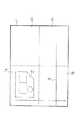
図2は3次元形状の作図方法の第1ステップの画面表示例を示す図である。
【0013】
図示のCADシステムの画面表示例によれば、表示領域1は4つの領域に分割され、平面図を作成する領域1aと、正面図を作成する領域1bと、側面図を作成する領域1cと、3次元形状の斜視図を表示する領域1dとによって構成されている。この例では、既に、平面図を作成する領域1aに、通常の2次元のCAD作図方法によって平面図が作成されており、その作成された図形2が表示されている。つまり、3次元形状の作図方法の第1ステップの状態を示している。また、分割された2つの領域に渡って上下方向および左右方向に延びているクロスヘアカーソル3が表示されている。このクロスヘアカーソル3は、その交点がたとえばマウスの操作に追従して移動し、これに伴って2本のヘアカーソルも互いに直角方向に画面上を移動する。
【0014】
図3は3次元形状の作図方法の第2ステップの画面表示例を示す図である。
次のステップでは、平面図の領域1aに作成された図形2のたとえば左辺の線分Se1を別の面、ここでは、正面図の領域1bに作成する。すなわち、クロスヘアカーソル3の縦方向のヘアカーソルを図形2の線分Se1に一致させながら、正面図の領域1b内にて、クロスヘアカーソル3の交点の位置P1に一点目の指示を与える。これによって、正面図の領域1b内に、図形2の輪郭線の左辺の線分Se1を含む図形の上側の稜または下側の稜を指示したことになる。
【0015】
図4は3次元形状の作図方法の第3ステップの画面表示例を示す図である。
次のステップでは、クロスヘアカーソル3の縦方向のヘアカーソルを位置P1に合わせた状態で、正面図の領域1b内の縦方向のヘアカーソル上でクロスヘアカーソル3を移動させ、所望の位置P2にて2点目の指示を与える。図示の例では、正面図の領域1b内にて、位置P2は位置P1の下方に位置しているので、1点目は図形2の線分Se1の上側の稜を指示し、2点目は図形2の線分Se1の下側の稜を指示したことになり、これらの2点指示によって図形2の厚さを定義したことになる。なお、線分創成の方法としては、上記のように「2点指定」によるものの他、「1点+方向および長さ指定」によるものなどがあるが、ここでは、「2点指定」の直線入力モードを使用する。
【0016】
図5は3次元形状の作図方法の第4ステップの画面表示例を示す図である。
前のステップで、位置P1および位置P2が指定されるとそれらの位置を端点とする線分Se2が正面図の領域1bに表示される。その後、正面図の領域1bにおける線分Se2の図形座標と平面図の領域1aにおける図形2の線分Se1の図形座標とによって規定される図形3次元形状Wが生成されて、領域1dに生成された3次元形状Wがワイヤフレームの形で表示される。さらに、生成された3次元形状Wを側面図に投影して得られた矩形が側面図の領域1cに表示される。この場合、矩形の2辺の長さが線分Se2および線分Se1に等しい形状になる。また、側面図の領域1cに表示される矩形は、その上辺の座標が正面図の領域1b内の位置P1と同じになり、下辺の座標が正面図の領域1b内の位置P2と同じになるよう位置決めされて表示される。
【0017】
図6は最終的に3次元形状が作図された画面表示例を示す図である。
上記の第2ないし第4ステップを平面図の領域1aの図形2の他の図形要素について同じように繰り返し実施することで、最終的には図6に示したような画面表示になり、領域1dに3次元ワイヤフレームモデルWが表示され、領域1cには側面図が生成されて表示される。なお、上記の例では、作図の順序として、先に平面図を作成しておき、この平面図を基にして正面図を作成したが、この順序に限定されず、作図途中で、新規に作図する面を正面図または側面図に適宜切り換えて新たな線分または図形要素を作成し、これら正面図または側面図の線分または図形要素を基にして平面図あるいは側面図または正面図を作成するようにしてもよい。
【0018】
3面図作成過程で、ある面内で既に作成された図形を基にして、他の面内で線分を創成する際に、ヘアカーソルによって既に作成された図形の線分または図形要素を認識することになる。上記の例では、他の面内で創成しようとする線分に対応する図形の線分がヘアカーソルの方向に一致している場合を示した。すなわち、平面図の領域1aにおける図形2の線分Se1はクロスヘアカーソル3の縦方向のヘアカーソルと同じ方向に配置されている。この場合は、正面図の領域1bに、縦方向のヘアカーソルを線分Se1に位置決めしながら位置P1およびP2を作成し、これら位置P1およびP2を端点とする線分Se2を作成する。平面図の線分Se1に対応して線分Se2の垂直線を正面図に描画した場合には、3次元ワイヤフレームモデルでは矩形の枠になり、側面図ではこれら線分Se1およびSe2を2辺とする矩形になる。描画する際の座標は、平面図および正面図上で捉えられた座標値を基に3次元形状が計算され、側面図への投影処理が行われて画面の所定の面に表示される。次に、縦方向のヘアカーソルとは別の方向に配置されている図形要素に対応した他の面における図形などの作成方法について以下に説明する。
【0019】
図7は水平線分を描く場合の画面表示例を示す図である。
図示の例では、平面図の領域1aに線分Se3が既に作成されていて、これに対応した図形を正面図の領域1bに作成する場合を示している。この場合、まず、クロスヘアカーソル3を移動して縦方向のヘアカーソルを線分Se3のたとえば左側の端点位置P3に合わせながら、正面図の領域1b内にて位置P4を指示し、同様に、線分Se3の右側の端点位置P5に合わせ、かつ、横方向のヘアカーソルを位置P4に合わせながら、正面図の領域1b内にて位置P6を指示する。これにより、位置P4およびP6を端点とする線分Se4が描画される。その後、平面図および正面図における線分Se3,Se4の座標からそれに対応する3次元形状の線分Se5が生成され、表示領域1dに描画される。さらに、線分Se5の側面図への投影処理が行われて点の要素が生成され、側面図の領域1cの座標位置P7にその点が表示される。
【0020】
図8は矩形を描く場合の画面表示例を示す図である。
図示の例では、平面図の領域1aに線分Se6が既に作成されていて、これに対応した矩形を正面図の領域1bに創成する場合を示している。この場合、まず、クロスヘアカーソル3を移動して縦方向のヘアカーソルを線分Se6のたとえば左側の端点位置P8に合わせながら、正面図の領域1b内にて位置P9を指示し、今度は、縦方向のヘアカーソルを線分Se6の右側の端点位置P10に合わせながら、正面図の領域1b内に位置P11を指示する。これにより、位置P9およびP11を対角線の端点とする矩形R1が創成される。その後、平面図における線分Se6の座標および正面図における矩形R1の座標からそれに対応する3次元ワイヤフレームモデルが生成されて、表示領域1dに3次元ワイヤフレームモデルが矩形の枠として描画される。そして、3次元ワイヤフレームモデルの側面図への投影処理にて線分Se7が生成され、側面図の領域1cに表示される。
【0021】
図9は円を基に矩形を描く場合の画面表示例を示す図である。
図示の例では、平面図の領域1aに円Cが既に作成されていて、これに対応した矩形を正面図の領域1bに創成する場合を示している。この場合、まず、クロスヘアカーソル3を移動して縦方向のヘアカーソルを円Cのたとえば左側の接点位置P12に合わせながら、正面図の領域1b内にて位置P13を指示し、次に、縦方向のヘアカーソルを円Cの反対側の接点位置P14に合わせながら、正面図の領域1b内に位置P15を指示する。これにより、位置P13およびP15を対角線の端点とする矩形R2が創成される。そして、平面図における円Cの円周の座標および正面図における矩形R2の座標からそれに対応する円筒の3次元ワイヤフレームモデルが生成され、その円筒の枠が表示領域1dに描画される。側面図の領域1cには、3次元ワイヤフレームモデルの側面図への投影処理にて生成された矩形R3が表示される。
【0022】
図10は点を基に線分を描く場合の画面表示例を示す図である。
図示の例では、平面図の領域1aにたとえば2本の線分が交差する点が既に作成されていて、これに対応した線分を正面図の領域1bに創成する場合を示している。この場合、まず、クロスヘアカーソル3を移動して縦方向のヘアカーソルを2本の線分が交差する点の位置P16に合わせながら、正面図の領域1b内にて位置P17を指示し、続いて、その位置P16に合わせながら別の位置P18を指示する。これにより、正面図の領域1bに位置P17およびP18を端点とする線分Se8が創成される。その後、平面図における点の座標および正面図における線分Se8の座標からそれに対応する3次元モデルの線分Se9が生成されて表示領域1dに描画される。また、3次元モデルの側面図への投影処理にて生成された線分Se10が側面図の領域1cに表示される。
【0023】
このようにして、各面、すなわち、平面図、正面図および側面図に表示される線分、円、円弧、点などの図形要素は、CADシステムのメモリ上で構造体の配列として管理されている。以下、その構造体の配列例について説明する。
【0024】
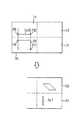
図11は図形要素のデータ構造の例を示す図である。
図形要素データは、要素を識別する番号と要素タイプに応じてそれぞれ定義された値との組によって管理されている。たとえば、図形の要素タイプが線分の場合は、構造体4aのように、要素IDと、線分の長さと、始点x座標と、始点y座標と、方向ベクトルxと、方向ベクトルyと、その他属性等とから定義される。要素タイプが円の場合は、構造体4bのように、要素IDと、半径と、中心x座標と、中心y座標と、その他属性等とから定義される。要素タイプが円弧の場合は、構造体4cのように、要素IDと、半径と、中心x座標と、中心y座標と、始角と、終角と、その他属性等とから定義されている。これらの図形要素データは、インデックスやリンクリストなどの一般的な方法にて管理されている。
【0025】
これらの図形要素データにアクセスするのは、オペレータがグラフィックディスプレイ装置上に表示されている図形要素を編集したり参照したりする場合である。このような場合には、通常、マウスポインタを図形要素に十分近い位置に合わせ、さらに、マウスボタンを押下するような操作によって、図形要素にアクセスする。これは、内部的には、マウス座標、またはマウスボタンを押下したときにカーソルボタンの位置する画面上の座標であるヒット座標と、メモリ上に管理されている全図形要素データとの比較検索操作により行われる。
【0026】
オペレータ操作の認識は主にマウスカーソル操作による。とりわけ、本発明では、3面図および3次元データの作成が目的なので、クロスヘアカーソルもしくは同等の機能を提供することができるある種のフィードバック手段が必要になる。これは、いずれも製図版上で設計する場合と同じような操作になる。画面上では編集または参照対象の図形要素をオペレータに認識させるフィードバック手段として、クロスヘアカーソルおよびこれにより検索された図形要素の強調表示(ハイライト)が一般的である。たとえば、図3において、平面図の線分Se1を参照して正面図を作成しようとするとき、その線分Se1は参照対象として検索された線分であるとして他の線分と区別するためにハイライト表示される。
【0027】
また、機械製図において、図面を描く場合、多くの場合は三角法の3面図である。つまり、3次元物体を3つの座標平面に投影し、さらにその3つの投影図は1枚の紙に配置される。3つの座標軸は、紙面上は通常は暗黙の了解がなされており、特に描画しないことになっている。ちなみに、平面図はxy軸、正面図はyz軸、側面図はzx軸の座標平面となる。ここで、平面図上のある要素を参照して正面図上に図形要素を作成した場合にはz軸の座標データが発生する。このときのデータの構造は、たとえば要素タイプが線分の場合、図11の構造体4aに始点z座標が追加されることになる。
【0028】
オペレータの操作に基づいて3次元データの座標を決定する手順について説明する。なお、以下の手順の説明において、説明を簡単にするため、平面図には既に図形要素が存在しているものとし、カーソル位置は正面図の領域内にあり、側面図には要素が存在していないものとする。
【0029】
図12は図形要素を作成するときの処理を示すフローチャートである。
平面図にある図形要素を参照して正面図に図形要素を作成する場合は、まず、参照対象の図形要素が検出されたかどうか、つまり、平面図において、クロスヘアカーソルのz軸方向の平面図にある図形要素の中に要素が存在するかどうかがチェックされ(ステップS11)、図形要素が検出されれば、その要素をハイライトしてその要素が選択の候補に上がっていることをオペレータに通知する(ステップS12)。ここで、マウスボタンが押下されると、そのハイライトしている要素は要素作成のために参照される要素として選択される(ステップS13)。次に、正面図にて作成しようとする図形要素は何であるかが判断される。まず、CADコマンドの中から、線分作成コマンドが選択されているかどうかが判断される(ステップS14)。ここで、もし、線分作成コマンドが選択されていると、線分作成処理に進み(ステップS15)、線分作成コマンドでなければ、円作成コマンドが選択されているかどうかが判断される(ステップS16)。ここで、円作成コマンドが選択されていると、円作成処理に進み(ステップS17)、円作成コマンドでなければ、矩形作成コマンドが選択されているかどうかが判断される(ステップS18)。ここで、矩形作成コマンドが選択されていると、矩形作成処理に進み(ステップS19)、矩形作成コマンドでなければ、円弧などのその他のコマンド処理を行う(ステップS20)。
【0030】
図13は線分作成処理を示すフローチャートである。
線分作成コマンドが選択されている場合、まず、カーソルを平面図のハイライトしている要素に合わせながら正面図にマウスボタンの押下によって1点目を入力する(ステップS21)。ここで、平面図において選択されてハイライトしている要素のタイプが判断される。まず、平面図で選択されている要素は線分であるかどうかが判断される(ステップS22)。ここで、要素タイプが線分であると判断されると、作成しようとする線分の他方の端点である2点目の入力があった後、3次元矩形の作成処理が行われ(ステップS23)、そして、作成された3次元矩形の側面図への投影処理が行われる(ステップS24)。要素タイプが線分でなく点であると判断された場合には(ステップS25)、2点目の入力が行われた後、3次元線分の作成処理が行われ(ステップS26)、作成された3次元線分の側面図への投影処理が行われる(ステップS27)。要素タイプが線分でも点でもなく円であると判断された場合には(ステップS28)、2点目の入力が行われた後、3次元円筒の作成処理が行われ(ステップS29)、作成された3次元円筒の側面図への投影処理が行われる(ステップS30)。
【0031】
なお、図12のステップS17の円作成処理およびステップS19の矩形作成処理においても、図13に示した線分作成処理と同様の処理が行われるので、ここでは線分作成処理のみにとどめ、円作成処理および矩形作成処理については省略する。
【0032】
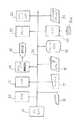
図14は本発明を実施するためのワークステーションのハードウエア構成の一例を示す図である。
図14において、ワークステーションは、プロセッサ11と、読み取り専用メモリ(ROM)12と、メインメモリ(RAM)13と、グラフィック制御回路14および表示装置15と、マウス16と、キーボード17と、タブレット18と、ハードディスク装置(HDD)19と、磁気テープ装置(MTD)20と、プロッタ21と、プリンタ22と、カラーハードコピー23とで構成され、これらの構成要素はそれぞれのインタフェースコントローラ(図示していない)およびバス24により相互に結合されている。
【0033】
プロセッサ11はワークステーション全体を統括的に制御する。読み取り専用メモリ12にはたとえば立ち上げ時に必要なプログラムなどが格納されている。メインメモリ13にはシステムプログラム、3次元モデル作成用CADシステムのアプリケーションプログラムなどが展開されている他に、作図、投影図あるいは編集中の要素データなどが生成、格納される。
【0034】
グラフィック制御回路14はフレームメモリなどを有し、メインメモリ13内で生成された2次元の線分データ、円データ、円弧データ、楕円データ、スプラインデータ、投影図データなどの各種図形要素データを表示信号に変換し、表示装置15に送る。表示装置15は、受けた表示信号を基にして図形要素から成る図面を表示する。
【0035】
マウス16は表示装置15の画面上に表示されているクロスヘアカーソルを移動させ、ボタンをクリックすることによってクロスヘアカーソルの交点またはヘアカーソルの下に存在する画面上の図形要素を選択したり、要素作成時の入力位置を指示するためのポインティングデバイスである。キーボード17は3次元ワイヤフレームモデルの視点方向を指定する数値データ、3面図のデータを保存するときのファイル名などを入力するのに使用される。
【0036】
ハードディスク装置19は、システムプログラム、3次元モデル作成用CADシステムの線分作成プログラム、円作成プログラム、矩形作成プログラムなどを含むアプリケーションプログラム、製図に必要な各種図形要素データなどが格納されている。磁気テープ装置20は磁気テープ20aに記憶されている設計図などのデータを入力したり、作成された設計図などのデータを磁気テープ20aに記憶させることができる外部記憶装置である。
【0037】
また、作成された設計図のデータは、プロッタ21、プリンタ22またはカラーハードコピー23によって出図することができる。
【0038】
【発明の効果】
以上説明したように本発明では、3面図の中の1つの面にて図形要素をあらかじめ作図しておき、他の面で作図する場合には、先に作図された図形に関連させて要素を作成していくことにより、残りの面には先の2つの面で作成された図形の座標を基にして生成された要素が表示されるようにした。このため、他の面の要素を参照して新たに要素を作図する場合には、2次元のCADシステムのような操作によって実施することができる。
【図面の簡単な説明】
【図1】 本発明方法の原理を説明したフローチャートである。
【図2】 3次元形状の作図方法の第1ステップの画面表示例を示す図である。
【図3】 3次元形状の作図方法の第2ステップの画面表示例を示す図である。
【図4】 3次元形状の作図方法の第3ステップの画面表示例を示す図である。
【図5】 3次元形状の作図方法の第4ステップの画面表示例を示す図である。
【図6】 最終的に3次元形状が作図された画面表示例を示す図である。
【図7】 水平線分を描く場合の画面表示例を示す図である。
【図8】 矩形を描く場合の画面表示例を示す図である。
【図9】 円を基に矩形を描く場合の画面表示例を示す図である。
【図10】 点を基に線分を描く場合の画面表示例を示す図である。
【図11】 図形要素のデータ構造の例を示す図である。
【図12】 図形要素を作成するときの処理を示すフローチャートである。
【図13】 線分作成処理を示すフローチャートである。
【図14】 本発明を実施するためのワークステーションのハードウエア構成の一例を示す図である。
【符号の説明】
1 表示領域
1a 平面図の領域
1b 正面図の領域
1c 側面図の領域
1d 3次元形状の斜視図表示領域
2 図形
3 クロスヘアカーソル[0001]
BACKGROUND OF THE INVENTION
The present invention relates to a method for drawing a three-dimensional shape, and in particular, a three-dimensional model (design data) in a three-dimensional CAD (computer aided design) system operating on a current computer having only a two-dimensional input device such as a mouse or a keyboard. The present invention relates to a method for drawing a three-dimensional shape in which a two-dimensional input means is input.
[0002]
In recent years, a three-dimensional CAD system has pursued ease of inputting a three-dimensional shape, and a function that can be easily and intuitively input by an end user (designer himself) has been demanded.
[0003]
[Prior art]
Generally, it is difficult to input a three-dimensional shape with a two-dimensional input device, and a kind of skill is required. Since each system has a different input method, it is very difficult for anyone to input a three-dimensional shape without training.
[0004]
As a conventional input method for drawing a three-dimensional shape, for example, there is a coordinate input method for directly inputting a three-dimensional coordinate value. This is a primitive method of creating a three-dimensional shape by connecting coordinate values that have been input with a line. In a method called sweep or swing, a contour is first created by a two-dimensional CAD-like operation, and a three-dimensional shape is created by a trajectory when the contour is moved or rotated in a certain direction. . Also, the method called CSG (Constructive Solid Geometry) or feature is to create a 3D shape by combining basic primitives of relatively simple shapes such as predefined rectangular parallelepipeds and cylinders, that is, primitives. It is. Neither method can completely represent the shape of all objects such as curved surfaces. Further, there is a method of generating a three-dimensional shape from a three-dimensional view. In this method, a three-dimensional shape is automatically created by designating coordinates corresponding to the same point on each surface based on a three-surface diagram created in advance.
[0005]
[Problems to be solved by the invention]
Typically, designers have knowledge and are trained in how to input a two-dimensional drawing. However, when designing in three dimensions, there is a problem that it is necessary to newly learn a design method using the conventional input method as described above, which requires time and labor.
[0006]
The present invention has been made in view of such points, and a drawing method of a three-dimensional shape that can be generated by an easy-to-understand operation of a three-dimensional model, that is, by a two-dimensional CAD-like three-dimensional drawing creation operation. The purpose is to provide.
[0007]
[Means for Solving the Problems]
FIG. 1 is a diagram illustrating the principle of the method of the present invention that achieves the above object.
According to the drawing method of a three-dimensional shape of the present invention, three surfaces are arranged and displayed in an L shape on one screen, and three surfaces of a plan view, a front view, and a side view are displayed on the three surfaces, respectively. When drawing a three-dimensional shape by creating a figure, first, a figure is drawn in advance on the first surface (step S1). Then, using the hair cursor passing through the adjacent first surface and second surface, the first construction point having a specific relationship with the first element of the graphic of the first surface is second The first drawing point is specified on the second surface (step S2), and the second drawing point having a specific relationship with the first element of the graphic on the first surface is designated on the second surface by the hair cursor. A second element representing the thickness direction of the first element of the graphic drawn on the first surface from the drawing point and the second drawing point is defined (step S3). Then, a third element defined by the first element on the first surface and the second element on the second surface is generated and displayed on the third surface (step S4). ). As a result, either a plan view, a front view, or a side view is drawn by a normal two-dimensional drawing method, and a figure related to the figure based on the drawn figure is adjacent to the first drawing surface. By drawing on the surface to be drawn, it is possible to newly generate and display a graphic on another surface.
[0008]
DETAILED DESCRIPTION OF THE INVENTION
First, an outline of the present invention will be described with reference to the drawings.
FIG. 1 is a flowchart illustrating the principle of the method of the present invention.
[0009]
In the system in which the drawing method of the three-dimensional shape according to the present invention is used, three surfaces are arranged in an L shape on one screen, and a plan view, a front view, and a side surface are displayed on the three surfaces, respectively. Three plane views of the figure can be created separately, and a three-dimensional shape is drawn by the figures created on these three planes.
[0010]
In order to draw a three-dimensional shape, a desired figure is first drawn in advance by a normal two-dimensional drawing method on a first surface which is one of a plan view, a front view, and a side view ( Step S1). Next, using a hair cursor passing through the adjacent first surface and second surface, the first construction point having a specific relationship with the first element of the graphic of the first surface is 2 is defined on the surface (step S2). After that, by designating the second drawing point having a specific relationship with the first element of the graphic of the first surface with the hair cursor on the second surface, the first drawing point and the first drawing point are designated. A second element representing the shape in the thickness direction of the figure drawn on the first surface from the drawing point of 2 is defined (step S3). And the 3rd element prescribed | regulated by the 1st element of the figure on the 1st surface and the 2nd element on the 2nd surface is produced | generated, and this is displayed on a 3rd surface ( Step S4).
[0011]
As described above, according to the method of the present invention, first, any one of a plan view, a front view, and a side view is drawn by a normal two-dimensional drawing method, and then this is based on the drawn figure. It is possible to generate and display a new graphic on another surface by drawing the graphic related to the item on the surface adjacent to the surface drawn first.
[0012]
Next, a case where the embodiment of the present invention is applied to a CAD system will be described as an example.
FIG. 2 is a diagram showing a screen display example of the first step of the method for drawing a three-dimensional shape.
[0013]
According to the screen display example of the illustrated CAD system, the
[0014]
FIG. 3 is a diagram showing a screen display example of the second step of the drawing method of the three-dimensional shape.
In the next step, for example, the left-side line segment Se1 of the
[0015]
FIG. 4 is a diagram showing a screen display example of the third step of the method for drawing a three-dimensional shape.
In the next step, with the vertical hair cursor of the
[0016]
FIG. 5 is a diagram showing a screen display example of the fourth step of the method for drawing a three-dimensional shape.
When the position P1 and the position P2 are designated in the previous step, a line segment Se2 having these positions as end points is displayed in the area 1b of the front view. Thereafter, a graphic three-dimensional shape W defined by the graphic coordinates of the line segment Se2 in the area 1b of the front view and the graphic coordinates of the line segment Se1 of the graphic 2 in the area 1a of the plan view is generated and generated in the area 1d. The three-dimensional shape W is displayed in the form of a wire frame. Furthermore, the generated three-dimensional shape W isSide view A rectangle obtained by projecting onto the side is displayed in a region 1c of the side view. In this case, the length of the two sides of the rectangle is equal to the line segment Se2 and the line segment Se1. The rectangle displayed in the side view region 1c has the same upper side coordinates as the position P1 in the front view region 1b and the lower side coordinates the same as the position P2 in the front view region 1b. Is positioned and displayed.
[0017]
FIG. 6 is a diagram showing a screen display example in which a three-dimensional shape is finally drawn.
Above2 The fourth step is repeated in the same manner for the other graphic elements of the graphic 2 in the area 1a in the plan view, so that the screen display as shown in FIG. 6 is finally obtained, and the three-dimensional wire is displayed in the area 1d. The frame model W is displayed, and a side view is generated and displayed in the area 1c. In the above example, as a drawing order, a plan view was created in advance, and a front view was created based on this plan view. However, the order is not limited to this. Create a new line segment or graphic element by switching the face to beFront view Or you may make it create a top view, a side view, or a front view based on the line segment or figure element of a side view.
[0018]
Recognize line segments or graphic elements already created by the hair cursor when creating a line segment in another plane based on a figure already created in one plane in the process of creating a three-view drawing Will do. In the above example, the case is shown in which the line segment of the figure corresponding to the line segment to be created in the other plane matches the direction of the hair cursor. That is, the line segment Se <b> 1 of the graphic 2 in the region 1 a in the plan view is arranged in the same direction as the longitudinal hair cursor of the
[0019]
FIG. 7 is a diagram showing a screen display example when a horizontal line segment is drawn.
In the illustrated example, the line segment Se3 has already been created in the area 1a of the plan view, and the corresponding figure is created in the area 1b of the front view. In this case, first, the position P4 is indicated in the area 1b of the front view while moving the
[0020]
FIG. 8 is a diagram showing a screen display example when a rectangle is drawn.
In the illustrated example, the line segment Se6 has already been created in the area 1a of the plan view, and a corresponding rectangle is created in the area 1b of the front view. In this case, first, the
[0021]
FIG. 9 is a diagram showing a screen display example when a rectangle is drawn based on a circle.
In the illustrated example, a circle C has already been created in the area 1a of the plan view, and a corresponding rectangle is created in the area 1b of the front view. In this case, first, the position P13 is indicated in the area 1b of the front view while the
[0022]
FIG. 10 is a diagram showing a screen display example when a line segment is drawn based on a point.
In the illustrated example, a point where, for example, two line segments intersect in the area 1a of the plan view has already been created, and a corresponding line segment is created in the area 1b of the front view. In this case, first, the position P17 is indicated in the area 1b of the front view while the
[0023]
In this way, graphic elements such as line segments, circles, arcs, and dots displayed on each plane, that is, the plan view, the front view, and the side view, are managed as an array of structures on the CAD system memory. Yes. Hereinafter, an example of the arrangement of the structures will be described.
[0024]
FIG. 11 is a diagram showing an example of the data structure of graphic elements.
The graphic element data is managed by a combination of a number for identifying the element and a value defined according to the element type. For example, if the shape element type is a line segment,Structure Like 4a, it is defined from the element ID, the length of the line segment, the start point x coordinate, the start point y coordinate, the direction vector x, the direction vector y, and other attributes. If the element type is a circle,Structure Like 4b, it is defined from the element ID, radius, center x coordinate, center y coordinate, and other attributes. If the element type is arc,Structure Like 4c, it is defined from the element ID, radius, center x coordinate, center y coordinate, start angle, end angle, and other attributes. These graphic element data are managed by a general method such as an index or a link list.
[0025]
The graphic element data is accessed when the operator edits or refers to the graphic element displayed on the graphic display device. In such a case, the graphic element is usually accessed by an operation such that the mouse pointer is positioned sufficiently close to the graphic element and the mouse button is pressed. This is internally when you press the mouse coordinates or mouse buttoncursor This is performed by a comparison search operation between hit coordinates, which are coordinates on the screen where the button is located, and all graphic element data managed in the memory.
[0026]
The recognition of the operator operation is mainly based on the mouse cursor operation. In particular, since the present invention aims to create three-dimensional views and three-dimensional data, a cross-hair cursor or some kind of feedback means that can provide an equivalent function is required. This is the same operation as when designing on the drafting plate. On the screen, as a feedback means for allowing an operator to recognize a graphic element to be edited or referred to, a crosshair cursor and highlighting (highlighting) of the graphic element retrieved thereby are generally used. For example, in FIG. 3, when creating a front view with reference to the line segment Se1 in the plan view, the line segment Se1 is distinguished from other line segments because it is a line segment searched as a reference object. Highlighted.
[0027]
Further, in drawing a machine, when drawing a drawing, in many cases, it is a trihedral view of trigonometry. That is, a three-dimensional object is projected onto three coordinate planes, and the three projections are arranged on a single sheet of paper. The three coordinate axes are usually implicitly understood on the paper, and are not drawn in particular. Incidentally, the plan view is the coordinate plane of the xy axis, the front view is the yz axis, and the side view is the coordinate plane of the zx axis. When a graphic element is created on the front view with reference to an element on the plan view, z-axis coordinate data is generated. For example, when the element type is a line segment, the data structure at this time is shown in FIG.Structure The starting point z coordinate is added to 4a.
[0028]
A procedure for determining the coordinates of the three-dimensional data based on the operation of the operator will be described. In the following description of the procedure, to simplify the explanation, it is assumed that the graphic element already exists in the plan view, the cursor position is in the area of the front view, and the element exists in the side view. Shall not.
[0029]
FIG. 12 is a flowchart showing a process for creating a graphic element.
When creating a graphic element in the front view with reference to a graphic element in the plan view, first, whether or not the graphic element to be referenced was detected,Plan view In step S11, it is checked whether an element exists in the graphic element in the plan view of the crosshair cursor in the z-axis direction (step S11). If a graphic element is detected, the element is highlighted and the element is The operator is notified that the selection is up (step S12). Here, when the mouse button is pressed, the highlighted element is selected as an element to be referenced for element creation (step S13). Next, it is determined what figure element is to be created in the front view. First, it is determined whether or not a line segment creation command is selected from the CAD commands (step S14). If the line creation command is selected, the process proceeds to the line creation process (step S15). If it is not the line creation command, it is determined whether the circle creation command is selected (step S15). S16). If the circle creation command is selected, the process proceeds to circle creation processing (step S17). If it is not the circle creation command, it is determined whether the rectangle creation command is selected (step S18). If the rectangle creation command is selected, the process proceeds to the rectangle creation process (step S19). If it is not the rectangle creation command, other command processes such as an arc are performed (step S20).
[0030]
FIG. 13 is a flowchart showing line segment creation processing.
When the line segment creation command is selected, first, the first point is input to the front view by pressing the mouse button while aligning the cursor with the highlighted element in the plan view (step S21). Here, the type of element selected and highlighted in the plan view is determined. First, it is determined whether or not the element selected in the plan view is a line segment (step S22). Here, if it is determined that the element type is a line segment, after the second input, which is the other end point of the line segment to be created, is input, a 3D rectangle creation process is performed (step S23). ), And a projection process to the side view of the created three-dimensional rectangle is performed (step S24). When it is determined that the element type is not a line segment but a point (step S25), after the second point is input, a three-dimensional line segment creation process is performed (step S26). The projection processing onto the side view of the three-dimensional line segment is performed (step S27). If it is determined that the element type is not a line segment or a point but a circle (step S28), after the second point is input, a three-dimensional cylinder creation process is performed (step S29). A projection process to the side view of the three-dimensional cylinder is performed (step S30).
[0031]
In the circle creation process in step S17 and the rectangle creation process in step S19 in FIG. 12, the same process as the line segment creation process shown in FIG. 13 is performed, so only the line segment creation process is performed here. The creation process and the rectangle creation process are omitted.
[0032]
FIG. 14 is a diagram showing an example of a hardware configuration of a workstation for carrying out the present invention.
In FIG. 14, the workstation includes a processor 11, a read only memory (ROM) 12, a main memory (RAM) 13, a
[0033]
The processor 11 comprehensively controls the entire workstation. The read-
[0034]
The
[0035]
The mouse 16 moves the crosshair cursor displayed on the screen of the
[0036]
The
[0037]
Further, the data of the created blueprint can be output by the
[0038]
【The invention's effect】
As described above, in the present invention, when a graphic element is drawn in advance on one side of a three-sided view and drawn on another side, the element is related to the previously drawn figure. By creating the above, the elements generated based on the coordinates of the graphic created on the previous two faces are displayed on the remaining faces. For this reason, when a new element is drawn with reference to an element on another surface, it can be implemented by an operation like a two-dimensional CAD system.
[Brief description of the drawings]
FIG. 1 is a flowchart illustrating the principle of a method of the present invention.
FIG. 2 is a diagram showing a screen display example of a first step of a method for drawing a three-dimensional shape.
FIG. 3 is a diagram showing a screen display example of a second step of a method for drawing a three-dimensional shape.
FIG. 4 is a diagram showing a screen display example of a third step of a method for drawing a three-dimensional shape.
FIG. 5 is a diagram showing a screen display example of a fourth step of the method for drawing a three-dimensional shape.
FIG. 6 is a diagram illustrating a screen display example in which a three-dimensional shape is finally drawn.
FIG. 7 is a diagram illustrating an example of a screen display when a horizontal line segment is drawn.
FIG. 8 is a diagram showing a screen display example when a rectangle is drawn.
FIG. 9 is a diagram illustrating a screen display example when a rectangle is drawn based on a circle.
FIG. 10 is a diagram illustrating a screen display example when a line segment is drawn based on a point.
FIG. 11 is a diagram illustrating an example of a data structure of a graphic element.
FIG. 12 is a flowchart showing processing when creating a graphic element.
FIG. 13 is a flowchart showing line segment creation processing;
FIG. 14 is a diagram illustrating an example of a hardware configuration of a workstation for carrying out the present invention.
[Explanation of symbols]
1 display area
1a Plan view area
1b Front view area
1c Side view area
1d Perspective view display area of 3D shape
2 figures
3 Crosshair cursor
Claims (7)
Translated fromJapaneseコンピュータが、
ポインティングデバイスからの指示に基づいて前記3つの面の内の第1の面上に図形を作成して表示する第1の作図ステップと、
前記第1の面と該第1の面に隣接する第2の面とを通過するヘアカーソルの下に、前記第1の作図ステップで表示した図形の第1の要素が存在しているときに、前記ポインティングデバイスからの指示に基づいて前記第2の面上に第1および第2の作図点を前記第1の要素と特定の関係を持たせて順次定義する定義ステップと、
前記定義ステップで定義した前記第1および第2の作図点から第2の要素を作成して前記第2の面上に表示する第2の作図ステップと、
前記第1の要素と前記第2の要素とによって規定される3次元形状を前記第2の面に隣接する第3の面に投影処理することにより第3の要素を生成して前記第3の面上に表示する第3の作図ステップと、
を実行することを特徴とする3次元形状の作図方法。A method of drawing a three-dimensional shape in which three planes are arranged and displayed in an L shape on one screen, and three plane views, a front view and a side view are created on the three planes, respectively. ,
Computer
A first drawing step of creating and displaying a graphic on a first surface of the three surfaces based on an instruction from a pointing device;
When the first element of the graphic displayed in the first drawing step exists under the hair cursor passing through the first surface and the second surface adjacent to the first surface. A definition step of sequentially defining the first and second drawing points on the second surface in a specific relationship with the first element based on an instruction from the pointing device;
A second drawing step of creating a second element from the first and second drawing points defined in the definition step and displaying the second element on the second surface;
It said first element and said second element and is thethree-dimensional shape of the third elementand the third to generate theby projection processing in the third surface adjacent said second surface defined by A third drawing step to display on the surface;
A method of drawing a three-dimensional shape, characterized in that
を更に実行することを特徴とする請求項1記載の3次元形状の作図方法。A fourth drawing step of creating and displaying a perspective view of a three-dimensional shape defined by the first to third elements on a fourth surface adjacent to the first to third surfaces; The method for drawing a three-dimensional shape according to claim 1, wherein:
前記第3の作図ステップは、前記ヘアカーソルを前記第1の要素に一致させた状態で前記定義ステップが前記第1および第2の作図点を定義し、前記要素タイプ判断ステップが前記第1の要素の要素タイプを線分と判断した場合に、前記第3の面上に前記第1の要素と前記第2の作図ステップが前記第1および第2の作図点から生成する前記第2の要素とによって規定される矩形を投影処理することにより矩形の前記第3の要素を生成して表示する In the third drawing step, the defining step defines the first and second drawing points in a state where the hair cursor is matched with the first element, and the element type determining step is the first drawing step. When the element type of an element is determined to be a line segment, the second element generated from the first and second drawing points on the third surface by the first element and the second drawing step The third element of the rectangle is generated and displayed by projecting the rectangle defined by
ことを特徴とする請求項1記載の3次元形状の作図方法。 The method for drawing a three-dimensional shape according to claim 1.
前記第3の作図ステップは、前記定義ステップが、前記ヘアカーソルを前記第1の要素の一端点および他端点に一致させた状態で、前記第1および第2の作図点をそれぞれ定義し、前記要素タイプ判断ステップが前記第1の要素の要素タイプを線分と判断した場合に、前記第3の面上に前記第1の要素と前記第2の作図ステップが前記第1および第2の作図点から生成する前記第2の要素とによって規定される点を投影処理することにより点の前記第3の要素を生成して表示する In the third drawing step, the defining step defines the first and second drawing points in a state where the hair cursor is matched with one end point and the other end point of the first element, respectively, When the element type determination step determines that the element type of the first element is a line segment, the first element and the second drawing step on the third surface are the first and second drawings. The third element of the point is generated and displayed by projecting a point defined by the second element generated from the point
ことを特徴とする請求項1記載の3次元形状の作図方法。 The method for drawing a three-dimensional shape according to claim 1.
前記第3の作図ステップは、前記定義ステップが、前記ヘアカーソルを前記第1の要素の一端点および他端点に一致させた状態で、前記第1および第2の作図点をそれぞれ定義し、前記要素タイプ判断ステップが前記第1の要素の要素タイプを線分と判断した場合に、前記第3の面上に前記第1の要素と前記第2の作図ステップが前記第1および第2の作図点から生成する矩形の前記第2の要素とによって規定される線分を投影処理することにより線分の前記第3の要素を生成して表示する In the third drawing step, the defining step defines the first and second drawing points in a state where the hair cursor is matched with one end point and the other end point of the first element, respectively, When the element type determination step determines that the element type of the first element is a line segment, the first element and the second drawing step on the third surface are the first and second drawings. The third element is generated and displayed by projecting a line segment defined by the second element of the rectangle generated from the point.
ことを特徴とする請求項1記載の3次元形状の作図方法。 The method for drawing a three-dimensional shape according to claim 1.
前記第3の作図ステップは、前記ヘアカーソルを前記第1の要素に一致させた状態で前記定義ステップが前記第1および第2の作図点をそれぞれ定義し、前記要素タイプ判断ステップが前記第1の要素の要素タイプを点と判断した場合に、前記第3の面上に前記第2の作図ステップが前記第1および第2の作図点から生成する前記第2の要素によって規定される線分を投影処理することにより線分の前記第3の要素を生成して表示する In the third drawing step, the defining step defines the first and second drawing points in a state where the hair cursor is matched with the first element, and the element type judging step is the first drawing step. When the element type of the element is determined to be a point, a line segment defined by the second element generated by the second drawing step from the first and second drawing points on the third surface The third element is generated and displayed by projecting
ことを特徴とする請求項1記載の3次元形状の作図方法。 The method for drawing a three-dimensional shape according to claim 1.
前記第3の作図ステップは、前記ヘアカーソルを前記第1の要素の一端点および他端点に一致させた状態で、前記定義ステップが前記第1および第2の作図点をそれぞれ定義し、前記要素タイプ判断ステップが前記第1の要素の要素タイプを円と判断した場合に、前記第3の面上に前記円の直径と前記第2の作図ステップが前記第1および第2の作図点から生成する矩形の前記第2の要素とによって規定される矩形を投影処理することにより矩形の前記第3の要素を生成して表示する In the third drawing step, the definition step defines the first and second drawing points in a state where the hair cursor is matched with one end point and the other end point of the first element. When the type determination step determines that the element type of the first element is a circle, the diameter of the circle on the third surface and the second drawing step are generated from the first and second drawing points. The third element of the rectangle is generated and displayed by projecting a rectangle defined by the second element of the rectangle
ことを特徴とする請求項1記載の3次元形状の作図方法。 The method for drawing a three-dimensional shape according to claim 1.
Priority Applications (3)
| Application Number | Priority Date | Filing Date | Title |
|---|---|---|---|
| JP00349696AJP4046370B2 (en) | 1996-01-12 | 1996-01-12 | 3D shape drawing method |
| US08/674,513US5852442A (en) | 1996-01-12 | 1996-07-02 | Method of drawing a three-dimensional object |
| GB9614954AGB2309142B (en) | 1996-01-12 | 1996-07-16 | Drawing three-dimensional objects in computer-aided design systems |
Applications Claiming Priority (1)
| Application Number | Priority Date | Filing Date | Title |
|---|---|---|---|
| JP00349696AJP4046370B2 (en) | 1996-01-12 | 1996-01-12 | 3D shape drawing method |
Publications (2)
| Publication Number | Publication Date |
|---|---|
| JPH09190551A JPH09190551A (en) | 1997-07-22 |
| JP4046370B2true JP4046370B2 (en) | 2008-02-13 |
Family
ID=11558960
Family Applications (1)
| Application Number | Title | Priority Date | Filing Date |
|---|---|---|---|
| JP00349696AExpired - LifetimeJP4046370B2 (en) | 1996-01-12 | 1996-01-12 | 3D shape drawing method |
Country Status (3)
| Country | Link |
|---|---|
| US (1) | US5852442A (en) |
| JP (1) | JP4046370B2 (en) |
| GB (1) | GB2309142B (en) |
Families Citing this family (13)
| Publication number | Priority date | Publication date | Assignee | Title |
|---|---|---|---|---|
| KR100232278B1 (en)* | 1996-07-05 | 1999-12-01 | 노부히로 세키 | Apparatus of drawing a cubic view |
| US5969721A (en)* | 1997-06-03 | 1999-10-19 | At&T Corp. | System and apparatus for customizing a computer animation wireframe |
| US6445974B1 (en)* | 1998-12-30 | 2002-09-03 | Intergraph Corporation | CAD-neutral application programming interface |
| US6603486B1 (en)* | 1999-09-13 | 2003-08-05 | Solidworks Corporation | Electronic drawing data translation |
| DE50102743D1 (en)* | 2000-04-11 | 2004-08-05 | Oce Printing Systems Gmbh | METHOD AND SYSTEM FOR REGISTERING PROCESSING OF PRINT DATA |
| US7620915B2 (en)* | 2004-02-13 | 2009-11-17 | Ludwig Lester F | Electronic document editing employing multiple cursors |
| CN100437594C (en)* | 2005-09-02 | 2008-11-26 | 鸿富锦精密工业(深圳)有限公司 | Figure element operating system and method |
| US7346408B2 (en)* | 2005-09-06 | 2008-03-18 | Esko Ip Nv | Two-dimensional graphics for incorporating on three-dimensional objects |
| US20090115782A1 (en)* | 2007-11-05 | 2009-05-07 | Darren Scott Irons | Display of Analytic Objects and Geometric Objects |
| CN101464870B (en)* | 2007-12-21 | 2011-03-23 | 鸿富锦精密工业(深圳)有限公司 | Cross-drawings copying system and method for stamping mold parts |
| WO2009135183A1 (en)* | 2008-05-02 | 2009-11-05 | Zentech, Inc. | Automated generation of 3d models from 2d computer-aided design (cad) drawings |
| US20150097829A1 (en)* | 2013-10-09 | 2015-04-09 | Cherif Atia Algreatly | 3D Modeling Using Unrelated Drawings |
| JP2017126240A (en)* | 2016-01-15 | 2017-07-20 | 日立Geニュークリア・エナジー株式会社 | Three-dimensional model display system and display method |
Family Cites Families (9)
| Publication number | Priority date | Publication date | Assignee | Title |
|---|---|---|---|---|
| US4685070A (en)* | 1984-08-03 | 1987-08-04 | Texas Instruments Incorporated | System and method for displaying, and interactively excavating and examining a three dimensional volume |
| NL8600831A (en)* | 1986-04-02 | 1987-11-02 | Oce Nederland Bv | METHOD FOR GENERATING AND EDITING MODELS OF TWO OR THREE DIMENSIONAL OBJECTS IN A COMPUTER AND DISPLAYING THESE MODELS ON A DISPLAY. |
| US4933865A (en)* | 1986-12-20 | 1990-06-12 | Fujitsu Limited | Apparatus for recognition of drawn shapes or view types for automatic drawing input in CAD system |
| US5265197A (en)* | 1988-12-23 | 1993-11-23 | Kabushiki Kaisha Toshiba | Geometric modeling apparatus |
| JP2892423B2 (en)* | 1990-02-28 | 1999-05-17 | 株式会社日立製作所 | Image display device and image display method |
| US5299307A (en)* | 1990-08-17 | 1994-03-29 | Claris Corporation | Controls for drawing images on computer displays |
| US5528735A (en)* | 1993-03-23 | 1996-06-18 | Silicon Graphics Inc. | Method and apparatus for displaying data within a three-dimensional information landscape |
| JP3333319B2 (en)* | 1994-06-03 | 2002-10-15 | 三菱電機株式会社 | 2D and 3D integrated CAD system |
| US5577176A (en)* | 1994-11-23 | 1996-11-19 | Computervision Corporation | Method and apparatus for displaying a cursor along a two dimensional representation of a computer generated three dimensional surface |
- 1996
- 1996-01-12JPJP00349696Apatent/JP4046370B2/ennot_activeExpired - Lifetime
- 1996-07-02USUS08/674,513patent/US5852442A/ennot_activeExpired - Lifetime
- 1996-07-16GBGB9614954Apatent/GB2309142B/ennot_activeExpired - Lifetime
Also Published As
| Publication number | Publication date |
|---|---|
| US5852442A (en) | 1998-12-22 |
| JPH09190551A (en) | 1997-07-22 |
| GB2309142A (en) | 1997-07-16 |
| GB9614954D0 (en) | 1996-09-04 |
| GB2309142B (en) | 2000-03-29 |
Similar Documents
| Publication | Publication Date | Title |
|---|---|---|
| US5371845A (en) | Technique for providing improved user feedback in an interactive drawing system | |
| EP0248919B1 (en) | Method for generating representations of 3-dimensional objects and system performing this method | |
| US6016147A (en) | Method and system for interactively determining and displaying geometric relationships between three dimensional objects based on predetermined geometric constraints and position of an input device | |
| JP4046370B2 (en) | 3D shape drawing method | |
| JP3599386B2 (en) | Edge mixing method | |
| JP2853355B2 (en) | 3D graphic data generator | |
| US5815150A (en) | Display apparatus | |
| JP2828271B2 (en) | Shape generation method in CAD system | |
| EP0535894A2 (en) | Apparatus and method for transforming a graphic pattern | |
| JP3672352B2 (en) | Three-dimensional configuration editing method and three-dimensional configuration editing apparatus | |
| JP3732174B2 (en) | Three-dimensional configuration editing method and three-dimensional configuration editing apparatus | |
| JPH0973476A (en) | Three-dimensional shape information input device | |
| JP2723058B2 (en) | Line-symmetric figure input device | |
| JP2755501B2 (en) | CAD system shape editing device | |
| JPH05134729A (en) | System for displaying dimension and parts number on three-dimensional image in cad/cam | |
| JP3591892B2 (en) | Character string display method and character string display device | |
| JP2836217B2 (en) | Parametric figure registration processing method | |
| JPS6334670A (en) | Three-dimensional coordinate value extraction method | |
| JPH04246786A (en) | 3D shape manipulation method | |
| JPH05314240A (en) | Three-dimensional shape data display method | |
| JPH07182400A (en) | 3D drawing method | |
| JPH0855244A (en) | 3D figure data input method | |
| JPH04372065A (en) | Interactive cad device | |
| JPH08305740A (en) | Graphic processing method and graphic processing apparatus | |
| JPH1031760A (en) | Graphic processing unit |
Legal Events
| Date | Code | Title | Description |
|---|---|---|---|
| A131 | Notification of reasons for refusal | Free format text:JAPANESE INTERMEDIATE CODE: A131 Effective date:20041130 | |
| A521 | Written amendment | Free format text:JAPANESE INTERMEDIATE CODE: A523 Effective date:20050127 | |
| A02 | Decision of refusal | Free format text:JAPANESE INTERMEDIATE CODE: A02 Effective date:20050802 | |
| A521 | Written amendment | Free format text:JAPANESE INTERMEDIATE CODE: A523 Effective date:20050928 | |
| A911 | Transfer to examiner for re-examination before appeal (zenchi) | Free format text:JAPANESE INTERMEDIATE CODE: A911 Effective date:20051017 | |
| A912 | Re-examination (zenchi) completed and case transferred to appeal board | Free format text:JAPANESE INTERMEDIATE CODE: A912 Effective date:20051104 | |
| A521 | Written amendment | Free format text:JAPANESE INTERMEDIATE CODE: A523 Effective date:20071026 | |
| A61 | First payment of annual fees (during grant procedure) | Free format text:JAPANESE INTERMEDIATE CODE: A61 Effective date:20071120 | |
| FPAY | Renewal fee payment (event date is renewal date of database) | Free format text:PAYMENT UNTIL: 20101130 Year of fee payment:3 | |
| R150 | Certificate of patent or registration of utility model | Free format text:JAPANESE INTERMEDIATE CODE: R150 | |
| FPAY | Renewal fee payment (event date is renewal date of database) | Free format text:PAYMENT UNTIL: 20101130 Year of fee payment:3 | |
| FPAY | Renewal fee payment (event date is renewal date of database) | Free format text:PAYMENT UNTIL: 20111130 Year of fee payment:4 | |
| FPAY | Renewal fee payment (event date is renewal date of database) | Free format text:PAYMENT UNTIL: 20111130 Year of fee payment:4 | |
| FPAY | Renewal fee payment (event date is renewal date of database) | Free format text:PAYMENT UNTIL: 20121130 Year of fee payment:5 | |
| FPAY | Renewal fee payment (event date is renewal date of database) | Free format text:PAYMENT UNTIL: 20121130 Year of fee payment:5 | |
| FPAY | Renewal fee payment (event date is renewal date of database) | Free format text:PAYMENT UNTIL: 20131130 Year of fee payment:6 | |
| EXPY | Cancellation because of completion of term |