JP4044810B2 - Gas supply device for surface treatment - Google Patents
Gas supply device for surface treatmentDownload PDFInfo
- Publication number
- JP4044810B2 JP4044810B2JP2002249105AJP2002249105AJP4044810B2JP 4044810 B2JP4044810 B2JP 4044810B2JP 2002249105 AJP2002249105 AJP 2002249105AJP 2002249105 AJP2002249105 AJP 2002249105AJP 4044810 B2JP4044810 B2JP 4044810B2
- Authority
- JP
- Japan
- Prior art keywords
- gas
- raw material
- passage
- surface treatment
- pipe
- Prior art date
- Legal status (The legal status is an assumption and is not a legal conclusion. Google has not performed a legal analysis and makes no representation as to the accuracy of the status listed.)
- Expired - Fee Related
Links
- 238000004381surface treatmentMethods0.000titleclaimsdescription34
- 239000002994raw materialSubstances0.000claimsdescription49
- 238000009834vaporizationMethods0.000claimsdescription11
- 230000008016vaporizationEffects0.000claimsdescription11
- 238000005304joiningMethods0.000claimsdescription5
- 239000007791liquid phaseSubstances0.000claimsdescription3
- 239000007789gasSubstances0.000description128
- XLYOFNOQVPJJNP-UHFFFAOYSA-NwaterSubstancesOXLYOFNOQVPJJNP-UHFFFAOYSA-N0.000description55
- 238000000034methodMethods0.000description35
- 239000007788liquidSubstances0.000description18
- 238000012545processingMethods0.000description13
- 230000005587bubblingEffects0.000description7
- 238000005259measurementMethods0.000description7
- 238000010926purgeMethods0.000description7
- 238000010438heat treatmentMethods0.000description6
- 238000002156mixingMethods0.000description6
- 238000003860storageMethods0.000description6
- 230000000052comparative effectEffects0.000description5
- 238000009833condensationMethods0.000description5
- 230000005494condensationEffects0.000description5
- 239000004065semiconductorSubstances0.000description4
- 239000000758substrateSubstances0.000description4
- OKKJLVBELUTLKV-UHFFFAOYSA-NMethanolChemical compoundOCOKKJLVBELUTLKV-UHFFFAOYSA-N0.000description3
- 238000005530etchingMethods0.000description3
- 238000002474experimental methodMethods0.000description3
- 239000000463materialSubstances0.000description3
- 230000002093peripheral effectEffects0.000description3
- 239000007921spraySubstances0.000description3
- LFQSCWFLJHTTHZ-UHFFFAOYSA-NEthanolChemical compoundCCOLFQSCWFLJHTTHZ-UHFFFAOYSA-N0.000description2
- 238000004380ashingMethods0.000description2
- 238000004140cleaningMethods0.000description2
- 230000000694effectsEffects0.000description2
- 238000001704evaporationMethods0.000description2
- 239000011344liquid materialSubstances0.000description2
- 229920006395saturated elastomerPolymers0.000description2
- 238000011144upstream manufacturingMethods0.000description2
- 239000006200vaporizerSubstances0.000description2
- IJGRMHOSHXDMSA-UHFFFAOYSA-NAtomic nitrogenChemical compoundN#NIJGRMHOSHXDMSA-UHFFFAOYSA-N0.000description1
- BOTDANWDWHJENH-UHFFFAOYSA-NTetraethyl orthosilicateChemical compoundCCO[Si](OCC)(OCC)OCCBOTDANWDWHJENH-UHFFFAOYSA-N0.000description1
- 150000001298alcoholsChemical class0.000description1
- 230000006837decompressionEffects0.000description1
- 238000010586diagramMethods0.000description1
- 229910001873dinitrogenInorganic materials0.000description1
- 230000005684electric fieldEffects0.000description1
- 230000008020evaporationEffects0.000description1
- 239000010419fine particleSubstances0.000description1
- 230000004907fluxEffects0.000description1
- 238000002488metal-organic chemical vapour depositionMethods0.000description1
- 239000000203mixtureSubstances0.000description1
- 238000012986modificationMethods0.000description1
- 230000004048modificationEffects0.000description1
- 239000002245particleSubstances0.000description1
- BDERNNFJNOPAEC-UHFFFAOYSA-Npropan-1-olChemical compoundCCCOBDERNNFJNOPAEC-UHFFFAOYSA-N0.000description1
- 238000005507sprayingMethods0.000description1
- 238000004804windingMethods0.000description1
Images


Landscapes
- Chemical Vapour Deposition (AREA)
- Drying Of Semiconductors (AREA)
Description
Translated fromJapanese【0001】
【発明の属する技術分野】
この発明は、半導体基板等の表面処理に用いる原料ガスを処理装置へ供給するガス供給装置に関し、特に、常圧下でグロー放電によりプラズマを生成して被処理物に吹き付け、CVD、洗浄、アッシング、エッチング等の表面処理を行なうシステムにおいて、液体の第1原料を気化させるとともに第2原料ガスと混合して供給するのに適した装置に関する。
【0002】
【従来の技術】
半導体基板のプラズマ表面処理の一例として、液体の第1原料を気化させ、更に他の第2原料ガスと混合する等して、プラズマ処理装置へ供給するものがある。この処理装置のプラズマ化空間が減圧されている場合には、気化後の再液化等の問題があまり無く、原料供給の装置構成が比較的容易である。一方、減圧設備を要し、コストもかさむため、近年、そのような設備が不要な常圧下でプラズマ処理する装置が種々開発されている。かかる常圧の処理装置では、液体原料の供給量等の精度を確保するのが難しく、改善の余地が残されている。
【0003】
ところで、表面処理用の液体原料供給手段として、液体原料を微粒化させて噴霧する所謂液体噴霧方式(特開2000−199066号公報等参照)や、液体原料中にガスを注入して泡立たせ、液体原料を気泡中に蒸発させて飽和蒸気を作る所謂バブリング方式(特開平4−261020号公報、特開平4−14827号公報等参照)や、液体原料を液体マスフローコントローラー(以下「MFC」という。)で計量後、気化器で気化させる所謂液体計量方式等が知られている。しかし、液体噴霧方式は、微粒とは言ってもガス状態に比べると粒径が大きく、噴霧濃度のばらつきも大きいので、高精度プロセスには不向きである。バブリング方式は、原料の温度、圧力、液面高さ、気泡の径などの細かい条件で蒸発量が変わり、管理が難しい。液体計量方式は、液体の小さな計量誤差が気化されると1000倍もの大きな誤差となる。また、計量した液体を100%気化させることを要する。
【0004】
以上の各方式に対して、所謂直接気化方式は、高精度が期待でき、常温プラズマ処理装置の原料供給手段として適していると考えられる。この方式では、液体の第1原料を気化させた後、気体MFCで計量し、別途、第2原料ガスを他の気体MFCで計量し、これら計量後の第1、第2原料を混合して処理装置へ導入する。
【0005】
【発明が解決しようとする課題】
上記の直接気化方式では、気化後の第1原料を通す管の外周にリボンヒータを巻き付けて加熱している。しかし、リボンヒータの巻きむらがあると、その部分の管内周面に第1原料が結露(再液化)し、混合割合や流量等の供給精度を確保できなくなってしまう。
この発明は、上記事情に鑑みてなされたものであり、その目的とするところは、所謂直接気化方式において、常圧プラズマ等の表面処理装置への処理用混合ガスの供給精度を確実に高く維持することにある。
【0006】
【課題を解決するための手段】
上記問題点を解決するために、本発明に係る表面処理用ガス供給装置は、容器状の装置本体と、気化されるべき液相の第1原料を溜めたタンクと、このタンクから気化した第1原料ガスを計量して所望流量にする第1計量手段と、この第1計量手段から延びる第1原料ガス路と、第2原料源からの第2原料ガスを計量して所望流量にする第2計量手段と、この第2計量手段から延び、上記第1原料ガス路と合流される第2原料ガス路と、これら原料ガス路の合流部から表面処理装置へ延びる混合ガス路とを備え、上記タンク、及び上記第1計量手段、並びに上記第1原料ガス路の上記合流部を含む全長域が、上記装置本体に収容され、この装置本体の内部が、上記第1原料の気化温度より高温に保持されていることを特徴とする。これによって、計量後の第1原料ガスが第2原料ガスと合流する前に再液化(結露)するのを確実に防止でき、ひいては表面処理装置への処理用混合ガスの供給精度を確実に高く維持することができ、高精度な表面処理を行なうことができる。
【0007】
上記第1、第2計量手段によって、上記第1原料ガス路と第2原料ガス路の流量比がこれらの流路断面積比と略等しくなるように調節されていることが望ましい。これによって、第1原料ガス路における第1原料ガスの流速と、第2原料ガス路における第2原料ガスの流速を互いに等しくすることができ、ひいては第1、第2原料ガスどうしを安定的に混合させることができる。
【0008】
上記合流部において、上記第1原料ガス路と第2原料ガス路の一方の下流端が、他方の路の内部に該他方の路と同軸をなして、しかも該他方の路の下流方向へ開口するようにして収容され、他方の路に上記混合ガス路がストレートに連なっていることが望ましい。これによって、一方のガスを他方のガスに均一に、しかもスムーズに混合でき、合流部の辺りで一方のガスが滞留しないようにすることができ、滞留による再液化を確実に防止することができる。ひいては、混合ガスの供給精度を一層確実に確保することができる。
【0009】
【発明の実施の形態】
以下、本発明の一実施形態を、図面を参照して説明する。
図1は、本実施形態に係るプラズマ表面処理システムS1を示したものである。システムS1は、常圧プラズマ表面処理装置10と、この処理装置10へのガス供給装置20とを備えている。処理装置10には、常圧環境下において半導体基板W(被処理物)と対向されるノズルヘッド11が設けられている。このノズルヘッド11内の一対の電極(図示せず)間に、上記供給装置20からの表面処理用ガスが導入されるとともに、電極間に例えばパルス状の電界が印加されて、上記導入ガスがグロー放電によりプラズマ化される。このプラズマ流が、半導体基板Wに吹付けられ、エッチング等の表面処理が施されるようになっている。
【0010】
表面処理用ガス供給装置20について説明する。
ガス供給装置20は、装置本体としての恒温槽21(気化器)と、この恒温槽21内に収容された貯水タンク22(第1原料タンク)及び水蒸気MFC23(第1計量手段)と、恒温槽21の外部に配置されたプロセスガスタンク30(第2原料源)及びプロセスガスMFC31(第2計量手段)とを備えている。
【0011】
槽21外のタンク30には、プロセスガス(第2原料ガス)として例えばCF4が貯留されている。タンク30は、MFC31の入口ポートに連なっている。MFC31は、タンク30からのCF4ガスの質量を計量し、所望流量にする。MFC31の出口ポートは、槽21の外面に配されたインレットポート21INに連ねられている。槽21の内部には、インレットポート21INから延びるプロセスガス管26(第2原料ガス路)が配管されている。プロセスガス管26には、エアコントロールバルブV26が設けられている。
【0012】
恒温槽21では、水が気化されて上記プロセスガスに添加、混合され、表面処理用の混合ガスが作られるようになっている。詳述すると、恒温槽21は、外部から断熱されるとともに、槽内ヒータ40(槽内加温手段)が組み込まれている。これによって、槽21の内部全体が、一定の温度に保たれている。この温度は、水の常圧下での気化温度より高くなるように(例えば110℃に)設定されている。
【0013】
槽21内のタンク22には、例えば電気伝導率0.1μS/cmの純水(液相の第1原料)が貯えられている。水面より上側のタンク22内には、水から蒸発した水蒸気(第1原料ガス)のみが存在し、空気等の不純ガスは殆ど含まれていない。槽21内において、タンク22の上端部からMFC23へ向けて計量前水蒸気管24が延びている。水蒸気管24には、2つのエアコントロールバルブV241,V242が上流側から順次設けられている。各バルブV241,V242には、リボンヒータ41,42(バルブ加温手段)が巻き付けられている。これらバルブV241,V242の間の水蒸気管24から排出管29が延び、槽21の外面に配された排出ポート21EXに連なっている。排出管29には、エアコントロールバルブV29が設けられている。水蒸気管24と排出管29との接合部には、圧力センサP1が設けられている。槽21の外面には、パージポート21PGが設けられ、このパージポート21PGから延びるパージ管28が、バルブV242より下流側の水蒸気管24に連なっている。パージ管28には、エアコントロールバルブV28が設けられている。
【0014】
水蒸気管24の下流端は、MFC23の入口ポートに連なっている。MFC23は、水蒸気管24ひいてはタンク22からの水蒸気の質量を計量し、所望流量にする。MFC23の出口ポートから計量後水蒸気管25(第1原料ガス路)が延びている。水蒸気管25の下流端は、上記プロセスガス管26と合流している。この合流部を含む水蒸気管25の全長域が、恒温槽21の内部に収容されている。
水蒸気管25には、エアコントロールバルブV25が設けられている。バルブV25には、リボンヒータ43(バルブ加温手段)が巻き付けられている。
【0015】
槽21内において、上記合流部から混合ガス管27(混合ガス路)が延びている。混合ガス管27は、槽21の外面に配されたアウトレットポート21OUTに連なっている。このアウトレットポート21OUTからガス導入管13が延び、上記ノズルヘッド11の電極間のプラズマ化空間に連なっている。
【0016】
上記プロセスガス管26と水蒸気管25との合流構造を更に詳述する。図2に示すように、プロセスガス管26と混合ガス管27とは、1本の共通のガス管20Xで構成されている。この共通ガス管20Xのストレートな中途部に、上記水蒸気管25の下流端部が接合されている。この接合部を境にして、それより上流側のガス管20Xがプロセスガス管26として提供され、下流側のガス管20Xが混合ガス管27として提供されている。
【0017】
水蒸気管25は、共通ガス管20Xより細くなっている。すなわち、水蒸気管25の流路断面積をA25とし、プロセスガス管26の流路断面積(=混合ガス路の流路断面積)をA26とすると、A25<A26になっている。水蒸気管25は、共通ガス管20Xの管壁を貫通して、管20X内に入り込むとともに、管20Xの管軸L20X上においてL字状に折り曲げられている。これにより、細い蒸気管25の下流端が、太い共通ガス管20Xと同軸をなして、下流の混合ガス管27の側へ向けて開口されている。
【0018】
上記のように構成された表面処理用ガス供給装置20の動作について説明する。
予め、窒素ガス等のパージガスをパージポート21PGから送り込むことにより、管24,25等の内部をパージする。更に、排出ポート21EXに真空ポンプを接続して、水面より上側のタンク22内や管24,25内の不明ガスを吸引、排気する。
【0019】
そのうえで、槽内ヒータ40をオンすることによって、恒温槽21内を水の気化温度より高い所望温度(例えば110℃)まで加温していく。これによって、貯水タンク22及びその内部の純水も加温されていく。この加温過程では、バルブV241,V29を開く一方、バルブV242を閉じておく。これによって、貯水タンク22内は、常圧に保たれる。また、リボンヒータ41〜43をオンし、蒸気管24,25のバルブV241,V242,V25を上記槽21内より高い所望温度(例えば120℃)まで個別的に加温していく。
【0020】
恒温槽21内ひいては貯水タンク22が所望の110℃で平衡に達した時、タンク22内の水は、100℃になっている。これによって、水が蒸発、気化し、水面より上側のタンク22内が飽和水蒸気で満たされる。ここで、蒸気管24,25のバルブV241,V242,V25を開く。(バルブV28,V29は閉にする。)これにより、飽和水蒸気が、タンク22から計量前蒸気管24を通ってMFC23へ送られていく。この時、蒸気管24も110℃まで加温されているので、水蒸気が蒸気管24の内周面に結露(再液化)することはない。更に、バルブV241,V242は、より高温の120℃に加温されているので、水蒸気がこれらバルブV241,V242内で結露するのを確実に防止できる。
【0021】
併行して、プロセスガス管26のバルブV26を開くとともに、槽21外のタンク30からCF4ガスをMFC31へ送る。
こうして飽和水蒸気又はCF4ガスを受け入れた2つのMFC23,31は、互いに協働して、次式が満たされるように各々からの送出流量を調節する。
Q25:Q26=A25:A26 …(式1)
ここで、Q25は、MFC23から蒸気管25へ送出される水蒸気の流量であり、Q26は、MFC31からインレットポート21INひいてはプロセスガス管26へ送出されるCF4ガスの流量である。勿論、水蒸気流量Q25は、水蒸気MFC23によって調節され、CF4ガスQ26は、プロセスガスMFC31によって調節される。A25及びA26は、上述した通り、各管25,26の流路断面積である。これによって、蒸気管25における飽和水蒸気の流速と、プロセスガス管26におけるCF4ガスの流速を互いに等しくすることができる。
【0022】
ここで、蒸気管25は、その全長にわたって110℃の高温に保たれているので、水蒸気が蒸気管25の内周面に結露することはない。これによって、蒸気管25を通過中の水蒸気の流量をMFC23で計量した正確な値に維持することができる。更に、バルブV25は、より高温の120℃に加温されているので、水蒸気がバルブV25内で結露することはなく、水蒸気の流量を正確な値に一層確実に維持することができる。
この結果、管25,26どうしの合流部において、プロセスガス管26からのCF4ガスに蒸気管25からの水蒸気を正確な分量で添加、混合することができる。
【0023】
しかも、上述したように、これらCF4ガス及び水蒸気は互いに等速になるように調節されているので、安定的に混合させることができる。また、蒸気管25の下流端が、共通ガス管20X内に同軸をなして収容されているので、水蒸気を均一に混合することができる。更に、蒸気管25の下流端開口が、下流側の混合ガス管27を向いているので、エジェクト効果によって、水蒸気の流速φ1を混合ガス管27のCF4ガスの流束φ2内に吸い込まれるようにしてスムーズに溶け込ませることができる。これによって、合流部の辺りで水蒸気が局所的に滞留しないようにすることができ、滞留による水蒸気の結露を確実に防止することができる。
この結果、極めて高精度な混合比や流量の表面処理用混合ガスを確実に得ることができる。ひいては、この混合ガスを導入管13を介して処理装置10のノズルヘッド11へ供給することにより、表面処理を高精度に行なうことができる。なお、混合ガス中の水蒸気は分圧が小さいので、導入管13内で結露することはない。
表面処理用ガス供給装置20では、貯水タンク22での気化用の加温手段と蒸気管24,25での結露防止用の加温手段とが、共通のヒータ40で構成されているので、部品点数の削減及び構成の簡素化を図ることできる。
【0024】
本発明は、上記実施形態に限定されず、種々の改変が可能である。
例えば、上記実施形態では、第1原料ガス路(管25)の下流端が第2原料ガス路(管26)内に収容されて合流され、第2原料ガス路(管26)が混合ガス路(管27)とストレートに連なっているが、これに代えて、第2原料ガス路の下流端が、第1原料ガス路の内部に収容されて合流され、第1原料ガス路に混合ガス路がストレートに連なっていてもよい。
気化されるべき液体の第1原料は、洗浄、アッシング、エッチング、CVD等の用途に応じて適宜選定することができる。例えば、純水の他、低級アルコール(メタノール、エタノール、プロパノール等)を用いてもよく、酸化膜原料としてはTEOS、TEMOSを用いてもよく、MOCVD用原料としてはβ−ジケトン系原料を用いてもよい。
本発明は、常圧下でのプラズマ表面処理に限定されず、真空チャンバー等を用いた減圧下でのプラズマ表面処理にも適用できる。
プラズマを用いた表面処理以外の表面処理にも広く適用できる。
【0025】
【実施例】
本発明の実施例を説明する。
[実施例1]
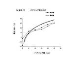
図1に示すガス供給装置20を用い、常温・常圧環境(25℃、湿度40%、760torr)で実験を行なった。プロセスガスとして340ccmのCF4を流し、これに添加する水蒸気量を変えて、プラズマ表面処理装置10に入る直前の導入路13で湿度(露点)を測定した。測定には鏡面式露点計を用いた。
結果を図3に示す。理論値からのずれは1%以内に抑えることができ、正確な混合ガス供給を安定的に行ない得ることが判明した。
[実施例2]
同様にして、プロセスガスとして80ccmのCF4を流し、露点測定を行なった。結果を図4に示す。理論値からのずれは1%以内に抑えることができ、正確な混合ガス供給を安定的に行ない得ることが判明した。プロセスガス小流量でも対応可能であることが確認できた。
【0026】
[比較例1]
比較例1として、所謂バブリング方式の装置を用い、常温・常圧環境(25℃、湿度40%、760torr)で実験を行なった。100ccmのプロセスガスを2つに分流し、0〜25ccmをバブリング容器の純水中に送りバブリングさせて水蒸気を含ませる一方、残りの100〜75ccmはバブリング容器をバイパスさせ、その後、これら2つの分流を合流させ、プラズマ表面処理装置の直前で露点温度を測定した。
結果を図5に示す。バブリング量と露点温度との再現性は得られず、理論値からのずれは大きかった。特にバブリング量が多くなるとばらつきが一層広がってしまった。この方式では水添加量を正確に制御するのは困難であると判明した。
[比較例2]
比較例2として、所謂液体計量方式の装置を用い、常温・常圧環境(25℃、湿度40%、760torr)で実験を行なった。純水1ccを液体MFCで計量した後、気化させ、これを100ccmのプロセスガスと混合し、プラズマ表面処理装置へ供給することを試みた。しかし、配管内で結露(再液化)が生じ、混合ガスの安定供給は難しかった。プロセスガスが小流量では対応困難であると判明した。
【0027】
【発明の効果】
以上説明したように、本発明によれば、計量後の第1原料ガスが第2原料ガスと合流、混合される前に再液化するのを確実に防止でき、ひいては表面処理装置への処理用混合ガスの供給精度を高くすることができ、高精度な表面処理を行なうことができる。
【図面の簡単な説明】
【図1】本発明の一実施形態に係るプラズマ表面処理システムの概略構成図である。
【図2】上記システムのプラズマガス管と蒸気管との合流部の断面図である。
【図3】本発明の実施例1の結果を示すグラフである。
【図4】本発明の実施例2の結果を示すグラフである。
【図5】比較例2の結果を示すグラフである。
【符号の説明】
10 プラズマ表面処理装置
20 表面処理用ガス供給装置
21 恒温槽(装置本体)
22 貯水タンク(第1原料タンク)
23 水蒸気MFC(第1計量手段)
25 計量後蒸気管(第1原料ガス路)
26 プロセスガス管(第2原料ガス路)
27 混合ガス管(混合ガス路)
30 プロセスガスタンク(第2原料源)
31 プロセスガスMFC(第2計量手段)
L20X プロセスガス管及び混合ガス管の共通の管軸[0001]
BACKGROUND OF THE INVENTION
The present invention relates to a gas supply apparatus that supplies a raw material gas used for surface treatment of a semiconductor substrate or the like to a processing apparatus, and in particular, generates plasma by glow discharge under normal pressure and sprays it on an object to be processed, CVD, cleaning, ashing, The present invention relates to an apparatus suitable for vaporizing a liquid first raw material and supplying it by mixing with a second raw material gas in a system for performing surface treatment such as etching.
[0002]
[Prior art]
As an example of the plasma surface treatment of the semiconductor substrate, there is a method of supplying a plasma processing apparatus by vaporizing a liquid first raw material and further mixing it with another second raw material gas. When the plasmaization space of this processing apparatus is depressurized, there are not many problems such as re-liquefaction after vaporization, and the apparatus configuration for raw material supply is relatively easy. On the other hand, since a decompression facility is required and the cost is increased, in recent years, various apparatuses for performing plasma processing under normal pressure that do not require such facility have been developed. In such a normal pressure processing apparatus, it is difficult to ensure the accuracy of the supply amount of the liquid raw material, and there remains room for improvement.
[0003]
By the way, as a liquid raw material supply means for surface treatment, a so-called liquid spraying method (see Japanese Patent Application Laid-Open No. 2000-199066) in which liquid raw material is atomized and sprayed, gas is injected into the liquid raw material, and foamed. A so-called bubbling method (see JP-A-4-2612020, JP-A-4-14827, etc.) for producing a saturated vapor by evaporating a liquid material into bubbles, and a liquid material is referred to as a liquid mass flow controller (hereinafter referred to as “MFC”). In other words, a so-called liquid measuring method in which vaporization is performed with a vaporizer after measurement is known. However, the liquid spray method is not suitable for a high-accuracy process because the particle size is large compared to the gas state and the variation in spray concentration is large even though it is a fine particle. The bubbling method is difficult to manage because the evaporation amount changes depending on fine conditions such as the temperature, pressure, liquid level, and bubble diameter of the raw material. In the liquid metering system, when a small liquid measurement error is vaporized, the error becomes 1000 times larger. Moreover, it is necessary to vaporize 100% of the measured liquid.
[0004]
For each of the above methods, the so-called direct vaporization method can be expected to have high accuracy, and is considered suitable as a raw material supply means for a room temperature plasma processing apparatus. In this method, after the liquid first raw material is vaporized, it is measured with a gas MFC, and the second raw material gas is separately measured with another gas MFC, and the first and second raw materials after mixing are mixed. Install in the processing equipment.
[0005]
[Problems to be solved by the invention]
In the above direct vaporization method, a ribbon heater is wound around the outer periphery of the tube through which the first raw material after vaporization is passed and heated. However, if there is uneven winding of the ribbon heater, the first raw material is condensed (reliquefaction) on the inner peripheral surface of that portion, and supply accuracy such as mixing ratio and flow rate cannot be secured.
The present invention has been made in view of the above circumstances, and an object of the present invention is to ensure that the supply accuracy of the processing gas mixture to the surface processing apparatus such as atmospheric pressure plasma is maintained high in a so-called direct vaporization system. There is to do.
[0006]
[Means for Solving the Problems]
In order to solve the above problems, a surface treatment gas supply device according to the present invention includes a container-like device body, a tank storing a liquid-phase first raw material to be vaporized, and a first gasified from the tank. A first metering means for metering one source gas to a desired flow rate, a first source gas path extending from the first metering means, and a second source gas from a second source source for metering to a desired flow rate. 2 metering means, a second source gas path that extends from the second metering means and merges with the first source gas path, and a mixed gas path that extends from the junction of these source gas paths to the surface treatment device, The tank, the first metering means, and the full length region including the merging portion of the first raw material gas path are accommodated in the apparatus main body, and the interior of the apparatus main body is higher than the vaporization temperature of the first raw material. It is characterized by being held in. As a result, it is possible to reliably prevent re-liquefaction (condensation) of the first raw material gas after measurement before joining the second raw material gas, and thus reliably increase the supply accuracy of the processing mixed gas to the surface treatment apparatus. The surface treatment can be performed with high accuracy.
[0007]
It is desirable that the flow rate ratio between the first raw material gas passage and the second raw material gas passage is adjusted by the first and second metering means so as to be approximately equal to the flow passage cross-sectional area ratio. Thus, the flow rate of the first source gas in the first source gas path and the flow rate of the second source gas in the second source gas path can be made equal to each other, and the first and second source gases can be stably connected. Can be mixed.
[0008]
In the merging portion, one downstream end of the first raw material gas passage and the second raw material gas passage is coaxial with the other passage inside the other passage, and opens in the downstream direction of the other passage. It is desirable that the mixed gas passage is connected straight to the other passage. Thereby, one gas can be mixed with the other gas uniformly and smoothly, and one gas can be prevented from staying around the junction, and reliquefaction due to stay can be reliably prevented. . As a result, the supply accuracy of the mixed gas can be further ensured.
[0009]
DETAILED DESCRIPTION OF THE INVENTION
Hereinafter, an embodiment of the present invention will be described with reference to the drawings.
FIG. 1 shows a plasma surface treatment system S1 according to this embodiment. The system S1 includes an atmospheric pressure plasma
[0010]
The surface treatment
The
[0011]
For example, CF4 is stored as a process gas (second source gas) in the
[0012]
In the
[0013]
The tank 22 in the
[0014]
The downstream end of the
The
[0015]
In the
[0016]
The merging structure of the
[0017]
The
[0018]
The operation of the surface treatment
In advance, a purge gas such as nitrogen gas is sent from the
[0019]
Then, by turning on the
[0020]
When the inside of the
[0021]
In parallel, the Directors opening the valve V26 of the
The two
Q25 : Q26 = A25 : A26 (Formula 1)
Here, Q25 is the flow rate of water vapor sent from the
[0022]
Here, since the
As a result, the water vapor from the
[0023]
In addition, as described above, the CF4 gas and the water vapor are adjusted so as to have the same speed, so that they can be mixed stably. Moreover, since the downstream end of the
As a result, it is possible to reliably obtain a mixed gas for surface treatment with a highly accurate mixing ratio and flow rate. As a result, by supplying this mixed gas to the nozzle head 11 of the
In the surface treatment
[0024]
The present invention is not limited to the above embodiment, and various modifications can be made.
For example, in the above-described embodiment, the downstream end of the first source gas passage (tube 25) is accommodated in the second source gas passage (tube 26) and merged, and the second source gas passage (tube 26) is the mixed gas passage. However, instead of this, the downstream end of the second raw material gas passage is accommodated and merged in the first raw material gas passage, and the mixed gas passage is connected to the first raw material gas passage. May be straight.
The liquid first raw material to be vaporized can be appropriately selected according to the use such as cleaning, ashing, etching, and CVD. For example, in addition to pure water, lower alcohols (methanol, ethanol, propanol, etc.) may be used, TEOS and TEMOS may be used as oxide film materials, and β-diketone materials are used as MOCVD materials. Also good.
The present invention is not limited to plasma surface treatment under normal pressure, but can also be applied to plasma surface treatment under reduced pressure using a vacuum chamber or the like.
It can be widely applied to surface treatment other than surface treatment using plasma.
[0025]
【Example】
Examples of the present invention will be described.
[Example 1]
Using the
The results are shown in FIG. The deviation from the theoretical value can be suppressed to within 1%, and it has been found that accurate mixed gas supply can be stably performed.
[Example 2]
Similarly, 80 ccm of CF4 was flowed as a process gas, and dew point measurement was performed. The results are shown in FIG. The deviation from the theoretical value can be suppressed to within 1%, and it has been found that accurate mixed gas supply can be stably performed. It was confirmed that it was possible to cope with a small flow rate of process gas.
[0026]
[Comparative Example 1]
As Comparative Example 1, a so-called bubbling apparatus was used, and an experiment was performed in a normal temperature / normal pressure environment (25 ° C.,
The results are shown in FIG. The reproducibility between the bubbling amount and the dew point temperature was not obtained, and the deviation from the theoretical value was large. In particular, as the bubbling amount increased, the variation further spread. This method proved difficult to accurately control the amount of water added.
[Comparative Example 2]
As Comparative Example 2, a so-called liquid metering system was used, and an experiment was performed in a normal temperature / normal pressure environment (25 ° C.,
[0027]
【The invention's effect】
As described above, according to the present invention, it is possible to reliably prevent the first raw material gas after measurement from being liquefied before joining and mixing with the second raw material gas, and thus for processing to the surface treatment apparatus. The supply accuracy of the mixed gas can be increased, and highly accurate surface treatment can be performed.
[Brief description of the drawings]
FIG. 1 is a schematic configuration diagram of a plasma surface treatment system according to an embodiment of the present invention.
FIG. 2 is a cross-sectional view of a joining portion of a plasma gas pipe and a steam pipe in the system.
FIG. 3 is a graph showing the results of Example 1 of the present invention.
FIG. 4 is a graph showing the results of Example 2 of the present invention.
5 is a graph showing the results of Comparative Example 2. FIG.
[Explanation of symbols]
DESCRIPTION OF
22 Water storage tank (first raw material tank)
23 Water vapor MFC (first metering means)
25 Steam pipe after measurement (first raw material gas passage)
26 Process gas pipe (second raw material gas passage)
27 Mixed gas pipe (mixed gas path)
30 Process gas tank (second raw material source)
31 Process gas MFC (second metering means)
Common tube axis for L20X process gas pipe and mixed gas pipe
Claims (2)
Translated fromJapanese上記タンク、及び上記第1計量手段、並びに上記第1原料ガス路の上記合流部を含む全長域が、上記装置本体に収容され、この装置本体の内部が、上記第1原料の気化温度より高温に保持されており、
上記第1、第2計量手段によって、上記第1原料ガス路と第2原料ガス路の流量比がこれらの流路断面積比と略等しくなるように調節されていることを特徴とする表面処理用ガス供給装置。A container-like device body, a tank in which a liquid-phase first raw material to be vaporized is stored, a first metering means for metering the first raw material gas vaporized from the tank to a desired flow rate, and the first metering A first source gas path extending from the means, a second metering means for metering the second source gas from the second source source to a desired flow rate, and extending from the second metering means and joining the first source gas path A second raw material gas passage, and a mixed gas passage extending from the junction of these raw material gas passages to the surface treatment device,
The tank, the first metering means, and the full length region including the merging portion of the first raw material gas path are accommodated in the apparatus main body, and the interior of the apparatus main body is higher than the vaporization temperature of the first raw material. Held inthe
Surface treatment characterized in that the flow rate ratio between the first source gas passage and the second source gas passage is adjusted by the first and second metering means so as to be substantially equal to the cross-sectional area ratio of these passages. Gas supply device.
Priority Applications (1)
| Application Number | Priority Date | Filing Date | Title |
|---|---|---|---|
| JP2002249105AJP4044810B2 (en) | 2002-08-28 | 2002-08-28 | Gas supply device for surface treatment |
Applications Claiming Priority (1)
| Application Number | Priority Date | Filing Date | Title |
|---|---|---|---|
| JP2002249105AJP4044810B2 (en) | 2002-08-28 | 2002-08-28 | Gas supply device for surface treatment |
Publications (2)
| Publication Number | Publication Date |
|---|---|
| JP2004087952A JP2004087952A (en) | 2004-03-18 |
| JP4044810B2true JP4044810B2 (en) | 2008-02-06 |
Family
ID=32056314
Family Applications (1)
| Application Number | Title | Priority Date | Filing Date |
|---|---|---|---|
| JP2002249105AExpired - Fee RelatedJP4044810B2 (en) | 2002-08-28 | 2002-08-28 | Gas supply device for surface treatment |
Country Status (1)
| Country | Link |
|---|---|
| JP (1) | JP4044810B2 (en) |
Families Citing this family (4)
| Publication number | Priority date | Publication date | Assignee | Title |
|---|---|---|---|---|
| JP4763443B2 (en)* | 2004-12-20 | 2011-08-31 | 東北リコー株式会社 | Diketone polymer and process for producing the same |
| JP2006294571A (en)* | 2005-04-14 | 2006-10-26 | Uinzu:Kk | Atmospheric pressure plasma processing apparatus and atmospheric pressure plasma processing method |
| JP4153961B2 (en) | 2006-04-25 | 2008-09-24 | 積水化学工業株式会社 | Etching method of silicon |
| CN109440088A (en)* | 2018-08-23 | 2019-03-08 | 福莱特玻璃集团股份有限公司 | A kind of attemperator for on-line coating glass production |
- 2002
- 2002-08-28JPJP2002249105Apatent/JP4044810B2/ennot_activeExpired - Fee Related
Also Published As
| Publication number | Publication date |
|---|---|
| JP2004087952A (en) | 2004-03-18 |
Similar Documents
| Publication | Publication Date | Title |
|---|---|---|
| US5372754A (en) | Liquid vaporizer/feeder | |
| TWI671425B (en) | Systems and methods for vapor delivery | |
| US8382903B2 (en) | Vaporizer and semiconductor processing system | |
| US8348248B2 (en) | Bubbling supply system for stable precursor supply | |
| JP2016035103A5 (en) | ||
| US20100203244A1 (en) | High accuracy vapor generation and delivery for thin film deposition | |
| TW201805467A (en) | Vapor delivery method and apparatus for solid and liquid precursors | |
| WO2002058141A1 (en) | Carburetor, various types of devices using the carburetor, and method of vaporization | |
| JP2009508332A (en) | Precursor gas transport with carrier gas mixing | |
| US12209310B2 (en) | Concentration control using a bubbler | |
| JPH0888191A (en) | Vaporization sequence method for many liquid precursors used in semiconductor thin film method | |
| JP4044810B2 (en) | Gas supply device for surface treatment | |
| JP4167542B2 (en) | Gas supply apparatus for plasma etching and plasma etching system and method | |
| JPH038330A (en) | Apparatus for vaporizing and supplying liquid material for semiconductor | |
| TW500994B (en) | Method and device for the measured delivery of low volumetric flows | |
| JP4167544B2 (en) | Plasma etching method and apparatus | |
| JPH03126872A (en) | Liquid semiconductor forming material vaporization supply device | |
| JP4445702B2 (en) | Liquid material vaporization supply apparatus, thin film deposition apparatus, and liquid material vaporization supply method to thin film deposition apparatus | |
| JPH07106254A (en) | Device and method for vaporization and supply equipment for liquid raw material | |
| TW202424252A (en) | Liquid-source precursor delivery system apparatus, reactor system, and method of using same | |
| KR100709035B1 (en) | Direct Liquid Injection System for Thin Film Deposition System | |
| KR102196514B1 (en) | System and method capable of maintaining steadily vaporization and preliminary purge | |
| JPH0559426A (en) | Method and apparatus for humidifying atmospheric gas in heat treatment furnace | |
| JPH0536268Y2 (en) | ||
| JPS6327052B2 (en) |
Legal Events
| Date | Code | Title | Description |
|---|---|---|---|
| A621 | Written request for application examination | Free format text:JAPANESE INTERMEDIATE CODE: A621 Effective date:20050617 | |
| A977 | Report on retrieval | Free format text:JAPANESE INTERMEDIATE CODE: A971007 Effective date:20070424 | |
| A131 | Notification of reasons for refusal | Free format text:JAPANESE INTERMEDIATE CODE: A131 Effective date:20070509 | |
| A521 | Written amendment | Free format text:JAPANESE INTERMEDIATE CODE: A523 Effective date:20070621 | |
| TRDD | Decision of grant or rejection written | ||
| A01 | Written decision to grant a patent or to grant a registration (utility model) | Free format text:JAPANESE INTERMEDIATE CODE: A01 Effective date:20071024 | |
| A61 | First payment of annual fees (during grant procedure) | Free format text:JAPANESE INTERMEDIATE CODE: A61 Effective date:20071116 | |
| FPAY | Renewal fee payment (event date is renewal date of database) | Free format text:PAYMENT UNTIL: 20101122 Year of fee payment:3 | |
| FPAY | Renewal fee payment (event date is renewal date of database) | Free format text:PAYMENT UNTIL: 20111122 Year of fee payment:4 | |
| FPAY | Renewal fee payment (event date is renewal date of database) | Free format text:PAYMENT UNTIL: 20111122 Year of fee payment:4 | |
| FPAY | Renewal fee payment (event date is renewal date of database) | Free format text:PAYMENT UNTIL: 20121122 Year of fee payment:5 | |
| LAPS | Cancellation because of no payment of annual fees |