JP4044763B2 - Electronic control system for construction machinery - Google Patents
Electronic control system for construction machineryDownload PDFInfo
- Publication number
- JP4044763B2 JP4044763B2JP2002007144AJP2002007144AJP4044763B2JP 4044763 B2JP4044763 B2JP 4044763B2JP 2002007144 AJP2002007144 AJP 2002007144AJP 2002007144 AJP2002007144 AJP 2002007144AJP 4044763 B2JP4044763 B2JP 4044763B2
- Authority
- JP
- Japan
- Prior art keywords
- communication
- data
- control device
- communication line
- prime mover
- Prior art date
- Legal status (The legal status is an assumption and is not a legal conclusion. Google has not performed a legal analysis and makes no representation as to the accuracy of the status listed.)
- Expired - Lifetime
Links
- 238000010276constructionMethods0.000titleclaimsdescription57
- 230000006854communicationEffects0.000claimsdescription525
- 238000004891communicationMethods0.000claimsdescription524
- 230000005540biological transmissionEffects0.000claimsdescription93
- 238000012806monitoring deviceMethods0.000claimsdescription33
- 238000003860storageMethods0.000claimsdescription24
- 238000012544monitoring processMethods0.000claimsdescription20
- 238000006243chemical reactionMethods0.000claimsdescription19
- 238000001514detection methodMethods0.000claimsdescription8
- 238000000034methodMethods0.000description92
- 238000012545processingMethods0.000description89
- 230000008569processEffects0.000description68
- 239000000446fuelSubstances0.000description47
- 230000005856abnormalityEffects0.000description41
- 239000010705motor oilSubstances0.000description40
- 238000010586diagramMethods0.000description30
- 230000006870functionEffects0.000description23
- 230000004044responseEffects0.000description13
- 239000000498cooling waterSubstances0.000description12
- XLYOFNOQVPJJNP-UHFFFAOYSA-NwaterSubstancesOXLYOFNOQVPJJNP-UHFFFAOYSA-N0.000description7
- 238000009826distributionMethods0.000description6
- 230000000694effectsEffects0.000description6
- 230000002159abnormal effectEffects0.000description4
- 238000009412basement excavationMethods0.000description4
- 230000008859changeEffects0.000description4
- 238000012423maintenanceMethods0.000description4
- 239000002826coolantSubstances0.000description3
- 238000003745diagnosisMethods0.000description3
- 239000000284extractSubstances0.000description3
- 239000003921oilSubstances0.000description3
- 238000011161developmentMethods0.000description2
- 230000006872improvementEffects0.000description2
- 238000004519manufacturing processMethods0.000description2
- 230000007246mechanismEffects0.000description2
- 230000004048modificationEffects0.000description2
- 238000012986modificationMethods0.000description2
- 230000007175bidirectional communicationEffects0.000description1
- 230000015556catabolic processEffects0.000description1
- 238000001816coolingMethods0.000description1
- 238000013075data extractionMethods0.000description1
- 238000006731degradation reactionMethods0.000description1
- 238000013461designMethods0.000description1
- 238000006073displacement reactionMethods0.000description1
- 230000001747exhibiting effectEffects0.000description1
- 238000007710freezingMethods0.000description1
- 230000008014freezingEffects0.000description1
- 239000010687lubricating oilSubstances0.000description1
- 230000008450motivationEffects0.000description1
- 238000002360preparation methodMethods0.000description1
- 230000002250progressing effectEffects0.000description1
- 230000009467reductionEffects0.000description1
- 230000002123temporal effectEffects0.000description1
Images


Classifications
- H—ELECTRICITY
- H04—ELECTRIC COMMUNICATION TECHNIQUE
- H04Q—SELECTING
- H04Q9/00—Arrangements in telecontrol or telemetry systems for selectively calling a substation from a main station, in which substation desired apparatus is selected for applying a control signal thereto or for obtaining measured values therefrom
- E—FIXED CONSTRUCTIONS
- E02—HYDRAULIC ENGINEERING; FOUNDATIONS; SOIL SHIFTING
- E02F—DREDGING; SOIL-SHIFTING
- E02F9/00—Component parts of dredgers or soil-shifting machines, not restricted to one of the kinds covered by groups E02F3/00 - E02F7/00
- E02F9/20—Drives; Control devices
- E02F9/22—Hydraulic or pneumatic drives
- E02F9/2246—Control of prime movers, e.g. depending on the hydraulic load of work tools
- E—FIXED CONSTRUCTIONS
- E02—HYDRAULIC ENGINEERING; FOUNDATIONS; SOIL SHIFTING
- E02F—DREDGING; SOIL-SHIFTING
- E02F9/00—Component parts of dredgers or soil-shifting machines, not restricted to one of the kinds covered by groups E02F3/00 - E02F7/00
- E02F9/20—Drives; Control devices
- E02F9/22—Hydraulic or pneumatic drives
- E02F9/2221—Control of flow rate; Load sensing arrangements
- E02F9/2225—Control of flow rate; Load sensing arrangements using pressure-compensating valves
- E02F9/2228—Control of flow rate; Load sensing arrangements using pressure-compensating valves including an electronic controller
- E—FIXED CONSTRUCTIONS
- E02—HYDRAULIC ENGINEERING; FOUNDATIONS; SOIL SHIFTING
- E02F—DREDGING; SOIL-SHIFTING
- E02F9/00—Component parts of dredgers or soil-shifting machines, not restricted to one of the kinds covered by groups E02F3/00 - E02F7/00
- E02F9/20—Drives; Control devices
- E02F9/22—Hydraulic or pneumatic drives
- E02F9/2221—Control of flow rate; Load sensing arrangements
- E02F9/2232—Control of flow rate; Load sensing arrangements using one or more variable displacement pumps
- E02F9/2235—Control of flow rate; Load sensing arrangements using one or more variable displacement pumps including an electronic controller
- E—FIXED CONSTRUCTIONS
- E02—HYDRAULIC ENGINEERING; FOUNDATIONS; SOIL SHIFTING
- E02F—DREDGING; SOIL-SHIFTING
- E02F9/00—Component parts of dredgers or soil-shifting machines, not restricted to one of the kinds covered by groups E02F3/00 - E02F7/00
- E02F9/20—Drives; Control devices
- E02F9/22—Hydraulic or pneumatic drives
- E02F9/2278—Hydraulic circuits
- E02F9/2296—Systems with a variable displacement pump
Landscapes
- Engineering & Computer Science (AREA)
- Mining & Mineral Resources (AREA)
- Civil Engineering (AREA)
- General Engineering & Computer Science (AREA)
- Structural Engineering (AREA)
- Physics & Mathematics (AREA)
- Fluid Mechanics (AREA)
- Computer Networks & Wireless Communication (AREA)
- Operation Control Of Excavators (AREA)
- Combined Controls Of Internal Combustion Engines (AREA)
- Control Of Vehicle Engines Or Engines For Specific Uses (AREA)
Description
Translated fromJapanese【0001】
【発明の属する技術分野】
本発明は、建設機械の原動機、油圧機器等を制御する複数の制御装置を共通の通信ラインを介して互いに接続し、ネットワークを構成してデータの送受信を行う建設機械の電子制御システムに関する。
【0002】
【従来の技術】
近年、建設機械は、性能向上あるいは多用途化に対する要望が大きく、それに対処するために電子制御化が進んでいる。そのため、それに係わる電子制御システムは高速の演算が必要となり、高機能のマイクロコンピュータの使用が不可避となっている。この結果、製造コストの増大や、システムの入出力信号が増加することによる制御装置およびワイヤ・ハーネスの複雑化といった問題が生じつつある。
【0003】
この問題に対処するため、制御対象である建設機械の制御機能を機能単位に分けて機能単位毎に制御装置(制御ユニット)を設ける一方、これらの制御装置をネットワークで結ぶことによって、建設機械全体の制御を行う制御装置を分散化することが検討されている。例えば、特公平8−28911号公報には、エンジン制御装置、ポンプ制御装置等、各機器毎に制御装置を設けるとともに、それら制御装置間を単一の多重伝送シリアル通信回路で結合することによって双方向通信が可能なネットワークを構成し、システムの拡張を容易にした建設機械の電子制御システムが開示されている。
【0004】
【発明が解決しようとする課題】
上記従来技術には、以下のような課題が存在する。
【0005】
一般に、建設機械において駆動源として搭載する原動機(エンジン)及びその制御のためのエンジン制御装置は、生産性の向上やコスト低減等の観点から、通常の自動車用(トラック等)のものを使用している場合が多い。
【0006】
ここで、自動車製造業界においては、上述したのと同様に、性能向上等の要望によって建設機械よりも先行して古くから電子制御化が進んでいる。そして、例えばエンジン制御に関しては、主として故障診断を目的として標準規格化された共通通信規格SAE J1939が策定され、この汎用の通信規格に沿ったインターフェースを備えたエンジン制御装置が使用されている。したがって、近年の建設機械では、このような自動車業界における汎用通信規格に沿ったインターフェースを備えたエンジン及びエンジン制御装置を搭載して用いる場合が多くなっている。
【0007】
このような近年の建設機械に対し上記従来技術を適用した場合、上述したように単一の多重伝送シリアル通信回線にすべての制御装置が接続され相互に通信する形態であることから、エンジン制御装置以外の他の全ての制御装置も、エンジン制御装置と同様に上記汎用の通信規格に沿ったインターフェースを備えることが必要となる。
【0008】
しかしながら、この場合、例えば以下のような不都合が生じる。
【0009】
▲1▼通信データ識別子に係わる不都合
すなわち、上記汎用の通信規格は、元々は自動車用、特に故障診断を目的として規定されたものであるため、自動車での使用を想定して予め多くの通信データ識別子が割り当て予約されている。しかしそれらの通信データ識別子は建設機械用としては不要なものが多いばかりか、逆に建設機械用として必要なものが不足している。なお、独自の通信データを余剰の識別子に割り当てることも許される構成となっているが、データ識別子は有限個であって且つ既にその多くは割り当て済みのため、余剰の識別子自体の数が少ない。このため、新たに建設機械に必要な固有のデータを新たにデータ通信中に加える余地が十分にない。
【0010】
▲2▼通信速度に係わる不都合
上記▲1▼で述べたように、上記汎用の通信規格は元々は自動車用に規定されたものである。しかしながら、建設機械は、自動車と同様の走行機構及びその制御系のみならず、例えば油圧ショベルではブーム、アーム、バケット等からなるフロント装置、上部旋回体等の機構にそれらを駆動する油圧駆動系、さらにそれらを制御する制御系が存在し、自動車に比べて制御のために必要な通信データの量が膨大である。このため、上記汎用の通信規格を用いた場合、その規定された通信速度のままではその膨大な量のデータを十分に通信することができず、建設機械の電子制御用としては通信量が不足してしまう。
【0011】
以上▲1▼及び▲2▼に例を挙げて説明したように、上記従来技術においては、近年の建設機械の電子制御用としては十分に機能させることができない。
【0012】
本発明は、汎用通信規格に沿ったインターフェースを備える近年の建設機械に対しても、十分な電子制御機能を発揮することができる建設機械の電子制御システムを提供することにある。
【0013】
【課題を解決するための手段】
(1)上記目的を達成するために、本発明は、原動機と、複数の作業装置と、前記原動機の駆動力を用いて油圧動力を発生し前記作業装置を駆動する複数の油圧機器とを備える建設機械に設けられ、前記原動機を制御する原動機制御装置及び前記油圧機器を制御する複数の油圧機器制御装置を含む複数の制御装置を有し、これら複数の制御装置を互いに接続しデータの送受信を行う建設機械の電子制御システムにおいて、データ通信のための共通バスとして設けられた汎用通信ラインであって、少なくとも前記原動機制御装置が接続され、汎用の通信規格に沿ったインターフェースに対応する汎用通信ラインと、データ通信のための共通バスとして設けられた専用通信ラインであって、前記複数の油圧機器制御装置が接続され、前記複数の油圧機器制御装置間で直接データの送受信を行うことを可能とする、上記汎用の通信規格とは異なる専用の通信規格に沿ったインターフェースに対応する専用通信ラインと、前記汎用通信ライン及び前記専用通信ラインに接続され、それら2系統の通信ラインのうち一方の通信ラインから受信した通信データを他方の通信ラインの通信規格に沿うように変換し、前記他方の通信ラインに送信する通信中継制御装置とを備え、前記原動機制御装置及び前記複数の油圧機器制御装置は、データの種類毎に設定された所定の通信周期でデータを送信する機能を有し、前記通信中継制御装置は、更に、前記2系統の通信ラインのうち一方の通信ラインから受信した通信データを他方の通信ラインの通信規格に沿うように変換して送信するとき、前記データの送信周期は、前記通信規格によらず、前記所定の通信周期を維持し、前記通信データをその通信周期で他方の通信ラインに送信するものとする。
【0014】
本発明においては、複数の制御装置のうち原動機制御装置については、汎用の通信規格に沿ったインターフェースに対応する汎用通信ラインに接続する一方で、複数の油圧機器制御装置については、汎用の通信規格とは異なる専用の通信規格に沿ったインターフェースに対応する専用通信ラインに接続する。そしてこれら規格の異なる通信ライン相互間でのデータ通信のために通信中継制御装置を設け、これによって一方の通信ラインから受信した通信データを他方の通信ラインの通信規格に沿うように変換して送信するようにする。また、原動機制御装置及び複数の油圧機器制御装置は、データの種類毎に設定された所定の通信周期でデータを送信する機能を有し、通信中継制御装置は、2系統の通信ラインのうち一方の通信ラインから受信した通信データを他方の通信ラインの通信規格に沿うように変換して送信するとき、データの送信周期は、前記通信規格によらず、前記所定の通信周期を維持し、通信データをその通信周期で他方の通信ラインに送信するようにする。
【0015】
このような構成とすることにより、原動機制御装置側では従来通り例えば自動車業界の汎用の通信規格に沿ったインターフェースを備えた構成とする一方で、原動機制御装置以外の油圧機器制御装置等に係わる専用通信ライン側では、汎用の通信規格にとらわれることなく独自の専用通信規格とし、建設機械の制御・情報収集等に最適な通信データの内容・通信周期等を独自に定義して使用することができる。この結果、本発明においては、汎用通信規格に沿ったインターフェースを備える近年の建設機械に適用する場合であっても、十分な電子制御機能を発揮することができる。
【0016】
また上記目的を達成するために、本発明は、原動機と、複数の作業装置と、前記原動機の駆動力を用いて油圧動力を発生し前記作業装置を駆動する複数の油圧機器とを備える建設機械に設けられ、前記原動機を制御する原動機制御装置及び前記油圧機器を制御する複数の油圧機器制御装置を含む複数の制御装置を有し、これら複数の制御装置を互いに接続しデータの送受信を行う建設機械の電子制御システムにおいて、データ通信のための共通バスとして設けられた汎用通信ラインであって、少なくとも前記原動機制御装置が接続され、汎用の通信規格に沿ったインターフェースに対応する汎用通信ラインと、データ通信のための共通バスとして設けられた専用通信ラインであって、前記複数の油圧機器制御装置が接続され、前記複数の油圧機器制御装置間で直接データの送受信を行うことを可能とする、上記汎用の通信規格とは異なる専用の通信規格に沿ったインターフェースに対応する専用通信ラインと、前記汎用通信ライン及び前記専用通信ラインに接続され、それら2系統の通信ラインから受信した通信データを通信規格によらない様式で一旦格納する格納手段、及び、前記2系統の通信ラインのうち一方の通信ラインから受信され前記格納手段に格納された通信データに関する送信要求が他方の通信ラインを介して受信されたとき、その格納されている通信データを前記他方の通信ラインの通信規格に沿うように変換して出力する変換手段を備えた通信管理制御装置とを有し、前記原動機制御装置及び前記複数の油圧機器制御装置は、データの種類毎に設定された所定の通信周期でデータを送信する第1通信機能及び一定の周期でデータ送信要求を送信する第2通信機能とを有し、前記原動機制御装置及び複数の油圧機器制御装置のうちデータ送信側は前記第1通信機能により前記所定の通信周期で前記通信管理制御装置にデータを送信し、前記原動機制御装置及び複数の油圧機器制御装置のうちデータ受信側は、前記第2通信機能により前記一定の周期でデータ送信要求を前記通信管理制御装置に送信し、前記通信管理制御装置からデータを受け取るものとする。
【0017】
これにより、通信管理制御装置は、複数の制御装置やモニタ装置等からの通信データをすべて集約して格納し一元管理することが可能となる。したがって、通信管理制御装置を介しデータ送信側の処理とデータ受信側の処理を独立させることができる。すなわちデータ送信側は自らの通常の制御周期の中でデータを通信管理制御装置側に送信すれば足り、データ受信側は自らの通常の制御周期の中でデータ送信要求を通信管理制御装置側に送信し通信管理制御装置からデータを受け取るだけで足りる。この結果、各制御装置における処理ステップ数を減少することができる。また、例えばデータ送信側ではデータ受信側からのデータ送信要求の割り込みに応じる形でデータを送信する必要は全くなくなるので、送信要求割り込み発生による処理低下を防ぐことができる。またデータ受信側ではデータ送信要求を送ってから実際にデータが送られてくるまでの遅れ時間が短縮されるので通信データ待ちによる処理低下を防ぐことができる。以上のようにして、各制御装置における通信処理負担及び制御処理負担を大きく低減することができる。
【0018】
(3)好ましくは、上記(1)又は(2)において、前記複数の制御装置は前記原動機制御装置と前記油圧機器制御装置との両方を含み、前記汎用通信ラインは前記原動機制御装置に接続され、前記専用通信ラインは前記油圧機器制御装置に接続されている。
【0019】
(4)また好ましくは、上記(1)〜(3)のいずれか1つにおいて、前記専用通信ラインに接続され、建設機械の運転状況を監視するための少なくとも1つのモニタ装置を設ける。
【0020】
(5)また好ましくは、上記(1)〜(4)のいずれか1つにおいて、建設機械の運転状態に係わる状態量を検出する複数のセンサをさらに備え、前記制御装置又は前記モニタ装置のうち少なくとも1つは、前記センサからの検出信号を収集する収集手段を備える。
【0021】
(6)さらに好ましくは、上記(5)において、前記検出信号を収集する制御装置又はモニタ装置は、その収集した検出信号に基づき、建設機械の各部位の稼動情報データ又は故障情報データを作成する情報作成手段を備える。
【0022】
【発明の実施の形態】
以下、本発明の実施の形態を図面を用いて説明する。
【0023】
本発明の第1の実施形態を図1〜図32により説明する。
【0024】
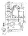
図1は、本発明の第1の実施形態による油圧ショベルの電子制御システムを、油圧ショベル及びこれに搭載される油圧システムと共に示す図である。この図1において、1は油圧ショベルであり、この油圧ショベル1は、下部走行体2、下部走行体2上に旋回可能に設けれられた上部旋回体3、上部旋回体3上に構成された原動機14や油圧ポンプ18等の収納室4、上部旋回体3の後部に設けたカウンタウエイト5、上部旋回体3の前部左側に設けられた運転室6、上部旋回体3の前部中央に設けられた掘削作業装置7を備えている。
【0025】
掘削作業装置7は、上部旋回体3に俯仰動可能に設けられたブーム8と、このブーム8の先端に回動可能に設けられたアーム9と、このアーム9の先端に回動可能に設けられたバケット10と、ブーム8を俯仰動させるブーム操作用の油圧シリンダ11と、アーム9を回動させるアーム操作用の油圧シリンダ12と、バケット10を回動させるバケット操作用の油圧シリンダ13とで構成されている。
【0026】
原動機14はディーゼルエンジンであり、その回転速度をある範囲に維持するための電子式のガバナ装置15を備えている。原動機(以下、適宜「エンジン」という)14の目標回転数Nrはスロットルダイヤル16により設定される。ガバナ装置15はエンジン14の実回転数を検出する機能を有している。
【0027】
油圧ポンプ18はエンジン14によって回転駆動される。また、油圧ポンプ18は可変容量型のポンプであり、その吐出量を変える斜板19を備え、この斜板19には吐出量調整装置20が連結されている。また、斜板19の傾転角を検出する斜板位置検出器21及び油圧ポンプ18の吐出圧力を検出する圧力検出器22が設けられている。
【0028】
エンジン14にはガバナ制御装置17が設けられ、この制御装置17はスロットルダイヤル16からの目標回転数Nrとガバナ装置15で検出された実回転数Neの各信号を入力し、それらの値に基づいて所定の演算を行い、実回転数Neが目標回転数Nrに一致するようにガバナ装置15に制御信号Rを出力する。
【0029】
油圧ポンプ18には車体制御装置23が設けられ、この車体制御装置23は、圧力検出器22によって検出された油圧ポンプ18の吐出圧力Pdと斜板位置検出器21によって検出された斜板19の傾転角θの各信号を入力し、それらの値に基づいて所定の演算を行い、油圧ポンプ18の吐出量調整装置20に斜板19の制御信号Tを出力する。
【0030】
ブーム操作用の油圧シリンダ11、アーム操作用のシリンダ12、バケット操作用のシリンダ13はそれぞれ制御弁24,25,26を介して油圧ポンプ18に接続され、制御弁24,25,26により油圧ポンプ18から各シリンダ11,12,13に供給される圧油の流量及び方向が調整される。
【0031】
制御弁24,25,26に対してはいわゆる電気レバー方式の操作レバー27,28,29が設けられ、各操作レバー27,28,29にレバー信号発生部30,31,32が連結され、これらのレバー信号発生部30,31,32は各操作レバー27,28,29の操作量に対応した電気信号を操作信号X1,X2,X3として出力する。
【0032】
操作信号X1,X2,X3は電気レバー制御装置33に入力され、この制御装置33は操作信号X1,X2,X3に基づいて所定の演算処理を行い、各制御弁24,25,26の操作部24L,24R,25L,25R,26L,26Rに制御信号を出力する。
【0033】
また、エンジン14には潤滑油の圧力を計測するための油圧センサ41、エンジンの冷却用水を冷却するラジエータ51に備えられた水温センサ42が備わり、これらのセンサの検出するエンジンオイル圧力(エンジン油圧)Poil、冷却水温Twの各信号はガバナ制御装置17へ入力され、エンジン14の異常状態監視のために用いられる。
【0034】
更に、この電子制御システムには油圧ショベル1の各機器の状態をモニタリングするためのセンサ類が設置されている。本実施の形態では、燃料残量を計測する燃料レベルセンサ43、及び油圧回路に備わるフィルタ50の目詰まりを検知するための圧力センサ44が設置されており、これらセンサのの検出する燃料レベルFuel、フィルタ圧力Pfltの各信号は車体情報モニタ装置45に入力される。車体情報モニタ装置45は、運転室6内に備わる計器パネル52上にそれらの情報をメータあるいは警報ランプなどの形態で表示する。
【0035】
また、電子制御システムには油圧ショベル1の稼動状況を記憶する稼動情報モニタ装置46が備わり、車体情報モニタ装置45及びガバナ制御装置17が出力した信号を通信で受け、これらを処理することで、油圧ショベル1の稼動時間、稼動状態を時系列的に、あるいは統計的に計測し、記憶する。例えばメンテナンスの際にこの稼働情報データを収集したいときは、例えばこのモニタ装置46にパーソナルコンピュータ(PC)53などの外部機器(外部情報端末)を接続して出力することができる。なおこのとき、各センサあるいは制御装置17,23,33若しくはモニタ装置45,46自体の故障の有無を判定する機能をモニタ装置46に持たせることができ、上記稼動情報データのみならずこの故障情報データもパソコン53等に出力可能としてもよい。
【0036】
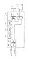
そして、本実施の形態の最も大きな特徴として、データ通信のための共通バスとして、車体制御装置23、電気レバー制御装置33、車体情報モニタ装置45、及び稼動情報モニタ装置46に接続され、制御データ及びモニタデータを通信するための独自規格の通信ライン39と、ガバナ制御装置17に接続された共通規格通信ライン40との2系統が設けられ、さらにこれら通信ライン39,40の間を中継するように通信中継制御装置100が接続されている。
【0037】
ガバナ制御装置17は、汎用の通信規格、例えば自動車業界において主として故障診断を目的として標準規格化された共通通信規格SAE J1939の通信規格に沿ったインターフェースを備えており、これに対応して、通信ライン40は、共通通信規格(汎用通信規格)に沿ったインターフェースに対応するものとなっている。
【0038】
その他の制御装置23,33およびモニタ装置45,46は上記ガバナ制御装置17と異なり、建設機械に適合するように独自の(専用の)通信規格に沿ったインターフェースを備えており、これに対応して通信ライン39は独自通信規格(専用通信規格)に沿ったインターフェースに対応するものとなっている。
【0039】
制御装置23,33及びモニタ装置45,46は通信ライン39を介して制御に必要とする信号(制御データ、モニタデータ等)を相互に送受信するとともに、通信中継制御装置100における変換機能(後述)によって、通信ライン40を介してガバナ制御装置17とも必要な信号を相互に送受信するようになっている。
【0040】
図2はガバナ制御装置17の機能的構成を表す機能ブロック図である。この図2において、制御装置17は、スロットルダイヤル16からの目標回転数信号Nr、油圧センサ41からのエンジン油圧Poil、水温センサ42からの冷却水温Twの各信号を切換え、A/D変換器171へ出力するマルチプレクサ170、マルチプレクサ170から受け取ったアナログ信号をデジタル信号に変換するA/D変換器171、ガバナ装置15からの実回転数Neの信号(パルス信号)を入力するカウンタ175、ROM173に記憶された制御手順のプログラムや制御に必要な定数に従って制御装置17全体を制御する中央演算処理装置(CPU)172、CPU172の行う制御手順のプログラムや制御に必要な定数を格納するリードオンリーメモリー(ROM)173、演算結果あるいは演算途中の数値を一時記憶するランダムアクセスメモリ(RAM)174、デジタル信号ををアナログ信号に変換するD/A変換器178、D/A変換器からの信号をガバナ装置15へ出力するための増幅器1780、通信ライン40を介した通信を制御する通信制御部176で構成される。
【0041】
図3は、車体制御装置23の機能的構成を表す機能ブロック図である。この図3において、制御装置23は、圧力検出器22の吐出圧力Pdと斜板位置検出器21からの斜板傾転角θの各信号を切換てA/D変換器231へ出力するマルチプレクサ230、マルチプレクサから入力したアナログ信号をデジタル信号に変換するA/D変換器231、中央演算処理装置(CPU)232、制御手順のプログラムや制御に必要な定数を格納するリードオンリーメモリー(ROM)233、演算結果あるいは演算途中の数値を一時記憶するランダムアクセスメモリ(RAM)234、油圧ポンプ18の斜板19の制御信号Tを駆動信号増幅器2390を介して斜板位置調節部20へ出力するインターフェース(I/O)239、通信ライン39を介した通信を制御する通信制御部236で構成される。
【0042】
図4は、電気レバー制御装置33の機能的構成を表す機能ブロック図である。この図4において、制御装置33は、操作レバー27,28,29のレバー信号発生部30,31,32からの操作信号X1,X2,X3を切換えA/D変換器331へ出力するマルチプレクサ330、マルチプレクサ330から入力したアナログ信号をデジタル信号に変換するA/D変換器331、ROM333に記憶された制御手順のプログラムや制御に必要な定数に従い制御装置全体を制御する中央演算処理装置(CPU)332、制御手順のプログラムや制御に必要な定数を格納するリードオンリーメモリー(ROM)333、演算結果あるいは演算途中の数値を一時記憶するランダムアクセスメモリ〈RAM)334、コントロールバルブ24,25,26に備えられた電磁比例弁24R,24L,25R,25L,26R,26Lへの駆動信号を増幅器3390〜3395を介して出力するデジタルの駆動信号をアナログ信号に変換するD/A変換器339、通信ライン39を介した通信を制御する通信制御部336で構成される。
【0043】
図5は、車体情報モニタ装置45の構成を表す機能ブロック図である。この図5において、モニタ装置45は、圧力センサ44からのフィルタ圧力Pflt、燃料レベルセンサ43からの燃料レベルFuelの各信号を切換てA/D変換器451へ出力すマルチプレクサ450、マルチプレクサから入力したアナログ信号をデジタル信号に変換するA/D変換器451、ROM453に記憶されたモニタリング手順のプログラムや演算に必要な定数に従いモニタ装置全体を制御する中央演算処理装置(CPU)452、モニタリング手順のプログラムや演算に必要な定数を格納するリードオンリーメモリー(ROM)453、演算結果あるいは演算途中の数値を一時記憶するランダムアクセスメモリ(RAM)454、燃料レベルFuel、フィルタ圧力Pfltの各信号、あるいは他の制御装置、モニタ装置から入力した信号に従い計器パネル52ヘ出力するインターフェース(I/O)458、通信ライン39を介した通信を制御する通信制御部457で構成される。
【0044】
図6は、稼動情報モニタ装置46の機能的構成を表す機能ブロック図である。この図6において、モニタ装置46は、ROM463に記憶されたモニタリング手順のプログラムや演算に必要な定数に従いモニタ装置全体を制御する中央演算処理装置(CPU)462、モニタリング手煩のプログラムや演算に必要な定数を格納するリードオンリーメモリー(ROM)463、演算結果あるいは演算途中の数値を一時記憶するランダムアクセスメモリ(RAM)464、ガバナ制御装置17、モニタ装置45から入力した信号に従い処理されたモニタリングデータを記憶する書き込み可能な不揮発性メモリ(EEPROM)4602、現在時刻を出力するリアルタイムクロック(RTC)4603、通信ライン39を介した通信を制御する通信制御部467、EEPROM4602に記憶されたモニタリングデータをPC53などの外部機器へ通信するための外部通信制御部4601で構成される。
【0045】
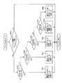
図7は通信中継制御装置100の機能的構成を表す機能ブロック図である。この図7において、通信中継制御装置100は、ROM103(後述)に記憶された制御手順のプログラムや制御に必要な定数に従って制御装置100全体を制御する中央演算処理装置(CPU)102、CPU102の行う制御手順のプログラムや制御に必要な定数を格納するリードオンリーメモリー(ROM)103、演算結果あるいは演算途中の数値を一時記憶するランダムアクセスメモリ(RAM)104、通信ライン39を介した通信を制御する通信制御部106、通信ライン40を介した通信を制御する通信制御部107で構成される。
【0046】
次に、通信ライン39,40による通信について説明する。
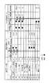
図8は、通信ライン39,40を介して通信するデータの一例を表す図である。この図8において、「IDNo.」は個々のデータにつけられる識別番号である。また○印は各制御装置又はモニタ装置の送信するデータを示しており、●印は各制御装置又はモニタ装置の受信データを示している。
【0047】
図8に示すように、制御系の通信データとしては、目標エンジン回転数Nr及び実エンジン回転数Neがガバナ制御装置17から送信され通信ライン40を経て通信中継制御装置100で変換された後に通信ライン39を経て車体制御装置23にて受信される。また操作信号X1,X2,X3が電気レバー制御装置33から送信され通信ライン39を経て車体制御装置23にて受信される。
【0048】
一方、モニタ系の通信データとしては、実エンジン回転数Ne、エンジン油圧Poil、及びエンジン冷却水温Twが、ガバナ制御装置17から送信され通信ライン40を経て通信中継制御装置100で変換された後に通信ライン39を経て車体情報モニタ装置45及び稼働情報モニタ装置46にて受信される。またフィルタ圧力Pflt及び燃料レベルFuelが、車体情報モニタ装置45から送信され通信ライン39を経て稼働情報モニタ装置46にて受信される。
【0049】
このとき、図中に示す「周期」は、そのデータを受信する制御装置又はモニタ装置側がそのデータを利用したい間隔、つまりデータを更新したい時間間隔を示している。この周期はそのデータが制御上、あるいはモニタリングで必要とされる、あるいはデータの変化速度を鑑みて決定される。例えば、ガバナ制御装置17から車体制御装置23にて受信するエンジン14の目標回転数Nrは一度設定されればほとんど変化しないことから50mS程度の周期で十分であるが、車体制御装置23にて受信するエンジン14の実回転数Neはその変化速度から20mSの周期が必要となる。また、電気レバー制御装置33から車体制御装置23にて送信する操作信号X1,X2,X3は制御装置23における油圧ポンプの目標傾転角θrの演算に必要であるため、その周期は10mS程度が必要となる。
【0050】
図9は、ガバナ制御装置17内の通信制御部176の構成の一例を示す機能ブロック図である。この図9において、図1及び図2に示す符号と同符号のものは同一部分を示す。通信制御部176はデータに付加されたIDNo.と同じ番号でデータを管理する記憶場所を有するメモリ80と、通信コントローラ81と、制御装置17内のCPU172に接続するデータライン82と、受信時において通信コントローラ81からCPU172に受信割り込み信号を送る割り込み信号ライン83と、通信コントローラ81と通信ライン40とを接続する受信ライン84及び送信ライン85で構成されている。
【0051】
なお、詳細な説明を省略するが、他の制御装置23,33及びモニタ装置45,46内の他の通信制御部236,336,457,467もほぼ同様に構成されている。
【0052】
次に、データの送受信方法の詳細を説明する。図8で説明したように、各データは受信側が必要とする所定の周期に従った送信が必要であり、データによって10msec程度から1sec程度まで周期に大きなばらつきがある。そこで、本実施形態においては、周期10〜100msecのデータ送受信、すなわちガバナ制御装置17→通信中継制御装置100→車体制御装置23と通信される目標エンジン回転数Nr及び実エンジン回転数Neや、電気レバー制御装置33→車体制御装置23と通信される操作信号X1,X2,X3や、ガバナ制御装置17→通信中継制御装置100→車体情報モニタ装置45及び稼働情報モニタ装置46と通信される実エンジン回転数Neは、送信側から当該周期ごとに自動的に送信するようにしている(詳細は後述)。
【0053】
一方、残りの周期1secのデータ送受信、すなわちガバナ制御装置17→通信中継制御装置100→車体情報モニタ装置45及び稼働情報モニタ装置46と通信されるエンジン油圧Poil及びエンジン冷却水温Twや、ガバナ制御装置17→車体情報モニタ装置45及び稼働情報モニタ装置46と通信されるフィルタ圧力Pflt及び燃料レベルFuelは、受信側からの送信要求に応じて送信側から送信するようにしている。
【0054】
(1)所定周期ごとの自動送受信(変換あり)
まず、上記した周期ごとの自動送受信の方法について説明する。一例として、ガバナ制御装置17から車体制御装置23へ目標エンジン回転数Nrを通信する場合を例にとり、最初にこの場合におけるガバナ制御装置17側のデータの送信方法を説明する。
【0055】
(1−1)送信
前述したガバナ制御装置17内のCPU172は、タイマ(図示せず)により一定時間毎、例えば1msec毎にタイマ割り込みを発生し、メイン処理(後述)を中断してタイマ割り込み処理プログラムを起動する。図10は、このタイマ割り込み処理プログラムを表すフローチャートである。この図10を用いて以下その処理手順の詳細を説明する。
【0056】
STEP5010:
各データ毎に設けられたカウンタをインクリメント(+1)する。つまりこのSTEPでタイマ割り込みが発生する毎に各カウンタを更新していく。例えばタイマ割り込みが1msec毎に実行されるのであれば各カウンタは1msec毎に更新される。
【0057】
STEP5020:
次に各カウンタの値が図8に示したデータ毎の送信周期に一致したか判定する。一致していない場合はそのままタイマ割り込み処理を終了してメイン処理へ戻る。STEP5020でカウンタ値が周期と一致したと判断された場合はSTEP5030以降へ処理が移る。
【0058】
STEP5030:
周期の一致したデータのカウンタ値をクリア(0)にする。
【0059】
STEP5040:
周期の一致した送信データを通信制御部176のメモリ80上のIDNoに相当する記憶場所に書き込む。
【0060】
STEP5050:
通信制御部176に送信処理を行わせるために通信コントローラ81の通信要求フラグをセットする。このSTEPが終了すると、タイマ割り込み処理を終え、メイン処理へ戻る。このとき、例えば、図8に示されているガバナ制御装置17の送信データ中、目標エンジン回転数Nrは通信周期が50msecなので、このタイマ割り込み処理を50回行う毎にカウンタ値が周期と一致してSTEP5030〜5050が実行されることとなる。
【0061】
以上のCPU172の処理が終了すると図9に示した通信制御部176内の通信コントローラ81が所定の送信処理を行い、制御データを通信ライン40ヘ送信する。図11は、この通信コントローラ81の送信処理動作の内容を表すフローチャートであり、この図11を用いて以下その処理手順の詳細を説明する。
【0062】
STEP6010:
通信コントローラ81内の送信要求フラグがセットされたかを監視し、セットされたら処理をSTEP6020へ進める。
【0063】
STEP6020:
CPU172によって書き込まれたメモリ80内の記憶場所のデータを読み出す。
【0064】
STEP6030:
読み出したデータに記憶場所に相当するIDを付加する。
【0065】
STEP6040:
共通規格の通信ライン40の空き状態を監視し、空いていたらSTEP6050へ処理を進める。
【0066】
STEP6050:
IDを付加したデータを時系列のシリアルデータに変換してデータパケット化し、通信ライン40ヘ送信する。
【0067】
STEP6060:
次のCPUからの送信要求を受け付けられるように通信コントローラ81内の送信要求フラグをリセットする。
【0068】
(1−2)中継及び変換
次に、通信中継制御装置100におけるデータの中継及び変換方法を説明する。
図12は、通信中継制御装置100が行う処理を表すフローチャートである。この図12を用いて以下その処理手順の詳細を説明する。
【0069】
STEP6510:
第2通信制御部107で、共通規格の通信ライン40から送信されてくる全てのデータを含むデータパケットを読み込む。
【0070】
STEP6520:
第2通信制御部107で、読み込んだデータパケットのうちIDNo.がCPU102により予め設定されているIDNo.のものを抽出する。
【0071】
STEP6530:
CPU102で、抽出したデータからIDNoを取り、データを、独自(専用)の規格様式に沿うようにデータパケットに付加される制御情報やデータサイズ、通信周期等を変換する。
【0072】
STEP6540:
CPU102で、変換したデータに、当初付与されていたIDに相当するIDを付加する。
【0073】
STEP6550:
第1通信制御部106で、独自規格の通信ライン39の空き状態を監視し、空いていたらSTEP6560へ処理を進める。
【0074】
STEP6560:
第1通信制御部106で、IDを付加したデータを時系列のシリアルデータに変換してデータパケット化し、通信ライン39ヘ送信する。
【0075】
(1−3)受信
最後に、車体制御装置23におけるデータの受信方法を説明する。図13は、車体制御装置23内の通信制御部236において通信コントローラ81が行う処理を表すフローチャートである。この図13を用いて以下その処理手順の詳細を説明する。
【0076】
STEP7010:
独自規格の通信ライン39から送信されてくる全てのデータを含むデータパケットを読み込む。
【0077】
STEP7020:
読み込んだデータパケットのうちIDNo.が通信コントローラ81にCPU232により予め設定されているIDNo.のものを抽出する。
【0078】
STEP7030:
抽出したデータからIDNoを取り、IDNoに相当するメモリ80内の記憶場所に書き込む。
【0079】
STEP7040:
CPU232に対し受信が完了したことを知らせるために通信コントローラ81内の受信割り込みフラグをセットし、CPU232に対して受信割り込み信号を発生する。
【0080】
CPU232では通信制御部236の通信コントローラ81からの受信割り込み信号を受け、メイン処理(後述)を中断して受信割り込み処理を行う。図14は、この受信割り込み処理を表すフローチャートである。この図14を用いて以下その処理手順の詳細を説明する。
【0081】
STEP8010:
通信制御部236内のメモリ80上のIDNoに相当する所定の記憶場所からデータを読み出し、RAM234へ書き込む。
【0082】
STEP8020:
通信コントローラ81内の受信割り込みフラグをリセットする。
以上説明したようにして、例えばガバナ制御装置17で50msec毎に送信した目標エンジン回転数Nrは、通信中継制御装置100にてデータが送信されてくる周期で変換された後、車体制御装置23において同じ周期で受信処理が行われる。図15は、以上の目標エンジン回転数Nrの通信の全体の流れを概略的にSTEP1001〜STEP1007としてまとめた処理フローである。
【0083】
なお、上記はガバナ制御装置17から車体制御装置23へ50msec毎に送信される目標エンジン回転数Nrを例にとって説明したが、ガバナ制御装置17から車体制御装置23へ送信される実エンジン回転数Neについても、周期が20msec毎であること以外は同様の処理が行われる。
【0084】
また、上記はガバナ制御装置17→通信中継制御装置100→車体制御装置23のデータ通信を例にとって説明したが、変換を伴う他のデータ通信、例えば実エンジン回転数Neがガバナ制御装置17→通信中継制御装置100→車体情報モニタ装置45及び稼動情報モニタ装置46へ周期100msecで通信される場合も、同様の処理、動作により通信ライン40,39を介したデータの送受信を行う。なお、通信中継制御装置100は、共通規格の通信ライン40側から独自規格の通信ライン39側への変換のみならず、その逆の変換も可能であることは言うまでもない。すなわち、独自規格の通信ライン39に接続された制御装置23,33およびモニタ装置45,46から出力される独自通信規格に準ずる通信データのうち、共通規格の通信ライン40上の制御装置17において必要なデータを、共通規格に沿うようにデータパケットに付加される制御情報やデータサイズ、通信周期等を変換し、通信ライン40上に送信する機能も備えている。
【0085】
(2)送信要求指令に応じた送受信(変換あり)
上記(1)は、送信側から所定周期毎に自動的に送信する場合を例にとって説明したが、前述したように、ガバナ制御装置17→通信中継制御装置100→車体情報モニタ装置45及び稼働情報モニタ装置46と通信されるエンジン油圧Poil及びエンジン冷却水温Twは、必要とされる周期が比較的長いことから、受信側からの送信要求に応じて送信側から送信するようにしている。この場合、ガバナ制御装置17は車体情報モニタ装置45及び稼動情報モニタ装置46の通信制御部457,467からの送信要求に応じて送信処理を行うこととなり、具体的にはガバナ制御装置17内のCPU172が上記送信要求に応じて割り込みを発生し、メイン処理(後述)を中断して送信要求割り込み処理プログラムを起動する。
【0086】
図16は、この送信要求割り込み処理プログラムを表すフローチャートであり、図10と同等の手順には同一の符号を付している。この場合、詳細な説明や図示は省略するが、車体情報モニタ装置45の通信制御部457(又は稼動情報モニタ装置46の通信制御部467、以下同様)から例えば1sec周期でガバナ制御装置17に対するエンジン油圧Poil(又はエンジン冷却水温Tw、以下同様)の送信要求指令信号が独自規格の通信ライン39に出力され、通信中継制御装置100のCPU102にて、その送信要求指令信号を、共通規格の通信ライン40における送信要求指令信号として適合するように変換した後、ガバナ制御装置17の通信制御部176にて受信される。
【0087】
このようにして送信要求指令信号が受信されると、図16に示す割り込み処理プログラムが起動し、まず、前述した図10と同様のSTEP5040において、送信データを通信制御部176のメモリ80上のIDNoに相当する記憶場所に書き込む。
【0088】
その後、STEP5050において通信制御部176に送信処理を行わせるために通信コントローラ81の通信要求フラグをセットする。このSTEPが終了すると、タイマ割り込み処理を終え、メイン処理へ戻る。
【0089】
このようにして、通信周期が1secごとにこの割り込み処理が行われSTEP5040及びSTEP5050が実行されることとなる。
【0090】
そして、以上のCPU172の処理が終了すると、前述の(1−1)と同様、ガバナ制御装置17の通信制御部176内の通信コントローラ81が所定の送信処理を行い、制御データを共通規格の通信ライン40ヘ送信する。この処理内容は、前述の図11のフローに示したものと同様のもので足りるので、説明を省略する。そして、これに対応して通信中継制御装置100にて中継・変換処理を行うが、これについても前述の図12のフローに示したものと同様で足りるので、説明を省略する。さらに、最後に車体情報モニタ装置45の通信制御部457にて行う受信処理も、前述の図13及び図14のフローに示したものと同様のもので足りるので、説明を省略する。
【0091】
図17は、以上のエンジン油圧Poilの通信の全体の流れを概略的にSTEP1501〜STEP1514としてまとめた処理フローである。
【0092】
(3)変換を伴わない送受信
上記(1)(2)はいずれも、ガバナ制御装置17から共通規格の通信ライン40を介し通信中継制御装置100で規格に対応した変換を行った後、独自規格の通信ライン39を介し車体制御装置23や車体情報モニタ装置45等にデータ通信を行う場合であったが、共通規格の通信ライン40を介した制御装置23,33及びモニタ装置45,46相互間では、通信中継制御装置100による変換を介さない直接のデータ送受信となる。
【0093】
この場合、上記(1)と同様、必要な周期が比較的短い電気レバー制御装置33→車体制御装置23と通信される操作信号X1,X2,X3については、送信側から当該周期ごとに自動的に送信するようにすればよい。この場合、電気レバー制御装置33内のCPU332にて図10に示したフローと同様のタイマ割り込み処理プログラムを行った後、通信制御部336内の通信コントローラ81が図11に示したフローと同様の(但しSTEP6040の「共通規格の通信ライン」を「独自規格の通信ライン」と読み替える)送信処理手順を行う。そしてこれに応じて車体制御装置23の通信制御部236の通信コントローラ81では図13に示したフローと同様の受信処理手順を行った後、これに応じてCPU23で図14に示したフローと同様の受信割り込み処理を行えば足りる。
【0094】
また、必要な周期が比較的長いガバナ制御装置17→車体情報モニタ装置45及び稼働情報モニタ装置46と通信されるフィルタ圧力Pflt及び燃料レベルFuelについては、さらに、上記(1)と同様にして、受信側からの送信要求に応じて送信側から送信するようにすればよい(詳細な説明は省略)。
【0095】
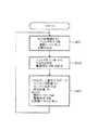
次に、各制御装置17,23,33及びモニタ装置45,46のメイン処理について説明する。
【0096】
まず、ガバナ制御装置17のメイン処理を図18を用いて説明する。
【0097】
図18は、ガバナ制御装置17のROM173に格納された制御プログラムを表すフローチャートである。ROM173は電源ON時にこの制御プログラムを起動し、次のような処理を行う。
【0098】
STEP1701:
制御演算に必要な定数をROM173から読み込む。
【0099】
STEP1702:
A/D変換器を介し、スロットルダイヤル16からの目標回転数Nr、エンジン油圧Poil、冷却水温Twの各信号を読み込む。
【0100】
STEP1703:
ガバナ装置15からのエンジン14の実回転数Neの信号をカウンタ175を介して入力する。
【0101】
STEP1704:
目標回転数Nrに実回転数Neが一致するようにガバナ装置15に制御信号Rを出力し、エンジン14の回転数が制御がされる。
【0102】
STEP1702へ戻り、処理を繰り返す。
【0103】
次に、車体制御装置23のメイン処理を図19を用いて説明する。
【0104】
図19は、車体制御装置23のROM233に格納された制御プログラムを表すフローチャートである。ROM233は電源ON時にこの制御プログラムを起動し、次のような処理を行う。
【0105】
STEP2301:
制御演算に必要な定数をROM233から読み込む。
【0106】
STEP2302:
A/D変換器を介し、圧力検出器22からの吐出圧力Pd及び斜板位置検出器21からの斜板傾転角θの各信号を読み込む。
【0107】
STEP2303:
前述したように通信中継制御装置100での変換を介しガバナ制御装置17から取得したNr,Neの通信データを用いエンジン14の負荷状態を演算する。
【0108】
STEP2304:
独自通信規格の通信ライン39を介し電気レバー制御装置33から直接取得したX1,X2,X3の通信データを用い油圧ポンプ18に要求される圧油の吐出量を演算する。
【0109】
STEP2305:
先に演算した油圧ポンプの要求吐出量を基にエンジンの負荷状態、及びPdから油圧ポンプが可能な吐出量を演算し、その吐出量から目標傾転角θrを計算する。
【0110】
STEP2306:
目標傾転角θrに斜板傾転角θが一致するように斜板位置調節部20に制御信号を出力し、油圧ポンプ18の斜板19の傾転角を制御する。
【0111】
STEP2302に戻り、処理を繰り返す。
【0112】
次に、電気レバー制御装置33のメイン処理を図20を用いて説明する。
【0113】
図20は、電気レバー制御装置33のROM333に格納された制御プログラムを表すフローチャートである。ROM333は電源ON時にこの制御プログラムを起動し、次のような処理を行う。
【0114】
STEP3301:
制御演算に必要な定数をROM333から読み込む。
【0115】
STEP3302:
A/D変換器331を介し、操作レバー27,28,29からの操作信号X1,X2,X3を読み込む。
【0116】
STEP3303:
操作信号X1,X2,X3に応じたバルブ操作量の演算を行う。
【0117】
STEP3304:
D/A変換器337、増幅器3390〜3395を介してコントロールバルブを駆動する比例弁24R〜26Lへ操作指令を出力し、STEP3302へ戻る。
【0118】
次に、車体情報モニタ装置45のメイン処理を図21を用いて説明する。
【0119】
図21は、車体情報モニタ装置45のROM453に格納された制御プログラムを表すフローチャートである。ROM453は電源ON時にこの制御プログラムを起動し、次のような処理を行う。
【0120】
STEP4501:
A/D変換器451を介してフィルタ圧力Pflt、燃料レベルFuelの各信号を入力する。
【0121】
STEP4502:
フィルタ圧力から目詰まりを判定し、警報信号Wfltを設定する。
【0122】
STEP4503:
I/O458を介して、前述したように通信中継制御装置100での変換を介し通信ライン39より入力したエンジン14の実回転数、エンジン油圧Poil、及び冷却水温Twと、先にSTEP4501で入力した燃料レベルFuel、警報信号Wfltの各値を計器パネルに表示する。
【0123】
STEP4501へ戻る。
【0124】
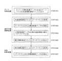
次に、稼動情報モニタ装置46のメイン処理を図22〜図30を用いて説明する。
【0125】
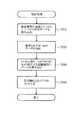
図22は、稼動情報モニタ装置46のROM463に記憶されている制御プログラムを表すフローチャートである。
【0126】
まず、モニタ装置46に電源が入りプログラムがスタートすると、ブロック9000の初期値設定が行われる。ここでは、後のブロック9100〜9400で使用されるエンジン稼動フラグ、エンジン油圧異常フラグ、フィルタ圧力異常フラグ、燃料残量警告フラグをOFF状態に設定する。
【0127】
次に、ブロック9100のエンジン稼動記録処理が行われる。その処理の詳細を図23に示す。以下、図23に従ってブロック9100の処理を説明する。
【0128】
STEP9101:
まず、前述したような通信中継制御装置100での変換を介し通信ライン39から受信したエンジン14の実回転数(エンジン回転数)Neがエンジンの稼動判定回転数N0より大きいか判定する。NeがN0より大きい場合、処理はSTEP9102へ進む。NeがN0より小さい場合はSTEP9106へ進む。この場合の稼動判定回転数N0は例えばエンジン14のアイドル回転数よりやや低いところに設定しておく。
【0129】
STEP9102:
エンジン回転数Neが稼動判定回転数N0より大きい場合、前回この処理が行われたときにエンジン14が稼動していたか否かを示すエンジン稼動フラグがON(稼動していたの意味)かどうか判定する。ONであった場合、前回と状態の変化が無いということなのでブロック9100の処理は終了する。OFFであった場合、処理はSTEP9103へ進む。初期状態ではこのエンジン稼動フラグはOFFなので、必ずSTEP9103へ進む。
【0130】
STEP9103:
エンジン稼動フラグをONにし、エンジン14が稼動したことを示す。
【0131】
STEP9104:
RTC4603より現在時刻を読み込む。
【0132】
STEP9105:
EEPROM4602にエンジンスタート時刻を記録する。EEPROM内では例えば図24に示したエンジン稼動記録のように「年、月、日、時刻、START」の形で記録する。そしてブロック9100を終了する。
【0133】
STEP9106:
一方、STEP9101でエンジン14の実回転数Neが稼動判定回転数N0より小さいと判定された場合、STEP9106が実行される。ここではエンジン稼動フラグがOFFであったか判定する。OFFであった場合は前回と変化が無いと言うことなのでブロック9100の処理は終了する。エンジン稼動フラグがONであった場合、処理はSTEP9107へ進む。
【0134】
STEP9107:
エンジン稼動フラグをOFFにし、エンジンが停止したことを示す。
【0135】
STEP9108:
RTC4603より現在時刻を読み込む。
【0136】
STEP9109:
EEPROM4602にエンジンストップ時刻を記録する。先に示したようにEEPROM内では例えば図24に示したエンジン稼動記録のように「年、月、日、時刻、STOP」の形で記録する。
【0137】
STEP9110:
次に、EEPROM4602のエンジン稼動記録に記憶されている最新のエンジンスタート時間を読み出し、その時刻と今回のエンジンストップ時刻の差で稼動時間を演算する。図24の例では最新のエンジンスタート時間は2000年1月28日、AM9時10分であり、今回のエンジンストップ時刻が2000年1月28日、PM4時30分なのでその差は7時間20分となる。この時間がエンジン14が稼動していた時間である。
【0138】
STEP9111:
次にEEPROM4602内に記憶されているエンジン累積稼動時間を読み出し、STEP9110で演算した稼動時間を加算して再度EEPROM4602内のエンジン累積稼動時間に記憶する。そしてブロック9100を終了する。
【0139】
ブロック9100を終了すると、次にブロック9200を実行する。図25は、ブロック9200の詳細手順を表すフローチャートである。以下、図25に従ってブロック9200を説明する。
【0140】
STEP9201:
まず、エンジン14が稼動中であるかをエンジン稼動フラグがONになっているかどうかで判定する。エンジン14が稼動していない(エンジン稼動フラグがOFFの)の場合はブロック9200を終了する。エンジン稼動中であればSTEP9202へ処理を進める。
【0141】
STEP9202:
前述のようにガバナ制御装置17から通信中継制御装置100での変換を経て通信ライン39を介し受信したエンジン油圧Poilが異常判定圧力P0より低いか判定する。低い場合は異常であると判定し、STEP9203へ処理を進める。エンジン油圧Poilが異常判定圧力P0より高い場合は、正常と判断してSTEP9207へ処理を進める。
【0142】
STEP9203:
STEP9202で異常と判断された場合、現在のエンジン油圧異常フラグがONであるか判定する。ONであった場合は異常状態が継続しているのでそのままブロック9200を終了する。エンジン油圧異常フラグがONでない、つまり、OFFであると判断されるとSTEP9204へ処理を進める。
【0143】
STEP9204:
エンジン油圧異常フラグをONにする。
【0144】
STEP9205:
RTC4603より現在時刻を読み出す。
【0145】
STEP9206:
EEPROM4602に図24に示すようにEEPROM内のエンジン油圧異常の記憶場所にエンジン油圧異常発生時刻を「年、月、日、時、分 ON」の形式で記憶する。そして、ブロック9200を終了する。
【0146】
この稼動情報モニタ装置46が起動した時は初期値設定9000でエンジン油圧異常フラグはOFFに設定される。従って、起動してから最初のエンジン油圧異常が発生した時点でSTEP9202−9203−9204−9205−9206の処理が行われ、エンジン油圧異常フラグがONになる。
【0147】
STEP9207:
一方、STEP9202においてエンジン油圧に異常が無い(Poil≧P0)と判断された場合、エンジン油圧異常フラグがOFFか判定する。OFFであればエンジン油圧が正常な状態が継続しているのでそのままブロック9200を終了する。エンジン油圧異常フラグがOFFでない、つまり、前回の処理サイクルまでエンジン油圧異常が起きていた場合はSTEP9208へ処理を進める。
【0148】
STEP9208:
エンジン油圧異常フラグをOFFにする。
【0149】
STEP9209:
RTC4603より現在時刻を読み出す。
【0150】
STEP9210:
EEPROM4602に図24に示すようにEEPROM内のエンジン油圧異常の記憶場所にエンジン油圧異常解除時刻を「年、月、日、時、分 OFF」の形式で記憶する。そして、ブロック9200を終了する。
【0151】
以上の説明のようにエンジン油圧の異常が発生または解除される毎に図24に示したようにEEPROM4602に記録していく。
【0152】
ブロック9200を終了すると、次にブロック9300を実行する。図26は、ブロック9300の詳細手順を表すフローチャートである。以下、図26に従ってブロック9300を説明する。
【0153】
STEP9301:
まず、エンジン14が稼動中であるかをエンジン稼動フラグがONになっているかどうかで判定する。エンジン14が稼動していない(エンジン稼動フラグがOFFの)の場合はブロック9300を終了する。エンジン稼動中であればSTEP9302へ処理を進める。
【0154】
STEP9302:
独自規格の通信ライン39を介し車体情報モニタ装置45から直接受信したフィルタ圧力Pfltが異常判定圧力P1より高いか判定する。高い場合は異常であると判定し、STEP9303へ処理を進める。フィルタ圧力Pfltが異常判定圧力P1より低い場合は、正常と判断してSTEP9307へ処理を進める。
【0155】
STEP9303:
STEP9302で異常と判断された場合、現在のフィルタ圧力異常フラグがONであるか判定する。ONであった場合は異常状態が継続しているのでそのままブロック9300を終了する。フィルタ圧力異常フラグがONでない、つまり、OFFであると判断されるとSTEP9304へ処理を進める。
【0156】
STEP9304:
フィルタ圧力異常フラグをONにする。
【0157】
STEP9305:
RTC4603より現在時刻を読み出す。
【0158】
STEP9306:
EEPROM4602に図24に示すようにEEPROM内のフィルタ圧力異常の記憶場所にフィルタ圧力異常発生時刻を「年、月、日、時、分 ON」の形式で記憶する。そして、ブロック9300を終了する。
【0159】
この稼動情報モニタ装置46が起動した時は初期値設定9000でフィルタ圧力異常フラグはOFFに設定される。従って、起動してから最初のフィルタ圧力異常が発生した時点でSTEP9302−9303−9304−9305−9306の処理が行われ、フィルタ圧力異常フラグがONになる。
【0160】
STEP9307:
一方、STEP9302においてフィルタ圧力に異常が無い(Pflt<P1)と判断された場合、フィルタ圧力異常フラグがOFFか判定する。OFFであればフィルタ圧力が正常な状態が継続しているのでそのままブロック9300を終了する。フィルタ圧力異常フラグがOFFでない、つまり、前回の処理サイクルまでフィルタ圧力異常が起きていた場合はSTEP9308へ処理を進める。
【0161】
STEP9308:
フィルタ圧力異常フラグをOFFにする。
【0162】
STEP9309:
RTC4603より現在時刻を読み出す。
【0163】
STEP9310:
EEPROM4602に図24に示すようにEEPROM内のフィルタ圧力異常の記憶場所にフィルタ圧力異常解除時刻を「年、月、日、時、分 OFF」の形式で記憶する。そして、ブロック9300を終了する。
【0164】
以上の説明のようにフィルタ圧力の異常が発生または解除される毎に図24に示したようにEEPROM4602に記録していく。
【0165】
ブロック9300を終了すると、次にブロック9400を実行する。図27はブロック9400の詳細手順を表すフローチャートである。以下、図27に従ってブロック9400を説明する。
【0166】
STEP9401:
独自規格の通信ライン39を介し車体情報モニタ装置45より直接受信した燃料レベルFuelが警告判定値F0より低いか判定する。低い場合は警告状態(燃料不足)であると判定し、STEP9402へ処理を進める。燃料レベルFuelが警告判定値F0より高い場合は、正常と判断してSTEP9406へ処理を進める。
【0167】
STEP9402:
STEP9401で警告状態(燃料不足)と判断された場合、現在の燃料残量警告フラグがONであるか判定する。ONであった場合は警告状態が継続しているのでそのままブロック9400を終了する。燃料残量警告フラグがONでない、つまり、OFFであると判断されるとSTEP9403へ処理を進める。
【0168】
STEP9403:
燃料残量警告フラグをONにする。
【0169】
STEP9404:
RTC4603より現在時刻を読み出す。
【0170】
STEP9405:
EEPROM4602に図24に示すようにEEPROM内の燃料残量警告の記憶場所に燃料残量警告発生時刻を「年、月、日、時、分 ON」の形式で記憶する。そして、ブロック9400を終了する。
【0171】
この稼動情報モニタ装置46が起動した時は初期値設定9000で燃料残量警告フラグはOFFに設定される。従って、起動してから最初の燃料残量警告が発生した時点でSTEP9401−9402−9403−9404−9405の処理が行われ、燃料残量警告フラグがONになる。
【0172】
STEP9406:
一方、STEP9401において燃料残量に燃料不足が無い(Fuel>F0)と判断された場合、燃料残量警告フラグがOFFか判定する。OFFであれば燃料残量が正常な状態が継続しているのでそのままブロック9400を終了する。燃料残量警告フラグがOFFでない、つまり、前回の処理サイクルまで燃料残量警告が起きていた場合はSTEP9407へ処理を進める。
【0173】
STEP9407:
燃料残量警告フラグをOFFにする。
【0174】
STEP9408:
RTC4603より現在時刻を読み出す。
【0175】
STEP9409:
EEPROM4601に図24に示すようにEEPROM内の燃料残量警告の記憶場所に燃料残量警告解除時刻を「年、月、日、時、分 OFF」の形式で記憶する。そして、ブロック9400を終了する。
【0176】
以上の説明のように燃料残量の警告が発生または解除される毎に図24に示したようにEEPROM4602に記録していく。
【0177】
ブロック9400を終了すると、次にブロック9500を実行する。図28はブロック9500の詳細手順を表すフローチャートである。以下、図28に従ってブロック9500を説明する。
【0178】
STEP9501:
まず、エンジン14が稼動中であるかをエンジン稼動フラグがONになっているかどうかで判定する。エンジン14が稼動していない(エンジン稼動フラグがOFFの)の場合はブロック9500を終了する。エンジン稼動中であればSTEP9302へ処理を進める。
【0179】
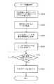
STEP9502〜9505:
前述のようにして通信中継制御装置100での変換を経て通信ライン39を介し受信した冷却水温Twが、
(1)Tw≧Tmax
(2)Tmax>Tw≧T2
(3)T2>Tw≧T1
(4)T1>Tw≧T0
(5)T0>Tw
の5領域のどこに当てはまるかを判定する。判定の結果、
(1)Tw≧Tmax…STEP9507へ
(2)Tmax>Tw≧T2…STEP9508へ
(3)T2>Tw≧T1…STEP9509へ
(4)T1>Tw≧T0…STEP9510へ
(5)T0>Tw…STEP9506へ
処理を進める。
【0180】
STEP9506〜9510:
図24の水温頻度分布に示すようにそれぞれの記憶場所にモニタ装置46のブロック9100〜9600の処理周期Δt時間(単位は例えばmS)を加算していく。例えばSTEP9502において、冷却水温TwがTmax以上であると判断された場合には処理はSTEP9507へ進む。そして、STEP9507においてEEPROM4602内の水温頻度分布のTw≧Tmaxの記憶場所に記録されている時間にΔtを加算する。
【0181】
この処理を継続して行くに従って、水温頻度分布の記憶場所には図24に示すように冷却水温の時間が累積され時間的な冷却水温の頻度分布が記録される。図24の例では、
(1)Tw≧Tmax…10hr
(2)Tmax>Tw≧T2…190hr
(3)T2>Tw≧T1…310hr
(4)T1>Tw≧T0…520hr
(5)T0>Tw…220hr
のようになっており、エンジン累積稼動時間1250hrである中で520hrがT1>Tw≧T0の範囲に入っていることが分かる。
【0182】
ここで使用している判定値Tmax,T2,T1,T0は機械本体の機種別に設定すればよい。例えばTmaxは設計上のオーバーヒート温度、T0は氷点温度0°C、他はTmaxからT0を等分した値のように決めればよい。
【0183】
以上でブロック9500を終了する。
【0184】
ブロック9500を終了すると、処理はブロック9600へ進む。ブロック9600はブロック9100〜9500でEEPROM4602に記録した各情報をモニタ装置46にパーソナルコンピュータ(PC)53を接続して出力する処理を示している。PC53は常に接続するのではなく、サービス員が車体の整備を行うときにモニタ装置46通信部4601の端子にPC53を接続して情報を出力する。
【0185】
図29は、稼動情報モニタ装置46の外部通信制御部4601の内部構成を表す機能ブロック図である。この図29において、外部通信制御部4601はPC53からシリアル信号のデータを受信するとこれをデジタルデータに変換して受信レジスタ90に記憶する。受信レジスタ90にデータが入力されると受信コントローラ91内の受信完了フラグがセットされる。CPU462はその受信完了フラグを監視することでデータの入力を知ることができる。また、CPU462からデータを送信する場合は、送信コントローラ93内にある送信レジスタの空き状態を示す送信フラグが空き状態(セット)されているかを監視し、送信フラグがセットされていることが確認できた場合にCPU462は送信レジスタ92にデジタルの送信データを書き込める。外部通信制御部4601は送信レジスタ92にデータが書き込まれると、自動的にシリアルのデータに変換してPCへ送信する。データは例えば文字コードであり、命令(コマンド)あるいは数値などを文字コードで送受信する。
【0186】
以上の外部通信制御部4601の機能を用いてPC53への通信を行う。図30は、外部通信制御部4601の行う処理手順を表すフローチャートである。
【0187】
STEP9601:
まず、外部通信制御部4601の受信フラグを見ることで、PC53からコマンド(文字コード)を受信していないか判定する。コマンドを受信していなければブロック9600を終了する。コマンドを受信していた場合はSTEP9602以下へ処理を進める。
【0188】
STEP9602〜9606:
文字コードをコマンドとして解釈する。それらの処理は次のようになる。
【0189】
(1)STEP9602:
コマンド(文字コード)が“T”…STEP9607へ
(2)STEP9603:
コマンド(文字コード)が“E”…STEP9608へ
(3)STEP9604:
コマンド(文字コード)が“P”…STEP9609へ
(4)STEP9605:
コマンド(文字コード)が“F”…STEP9610へ
(5)STEP9606:
コマンド(文字コード)が“W”…STEP9611へ
(6)STEP9606:
コマンド(文字コード)が“W”以外…ブロック9600終了
STEP9607〜9611:
コマンドが判定されるとSTEP9607〜9611において、図24に示すEEPROM4602内の記録データをPC53へ出力する。出力方法ば、例えば記録されている内容を文字コード列に変換し、第3通信部4621内の送信コントローラ93内の送信フラグの状況を確認しながら送信レジスタ92に一文字ずつ送り、送信レジスタ92がシリアルデータに変換してPC53へ送る。または、文字コードに変換せず、数値のまま送信しても良い。
【0190】
例えば、STEP9602でコマンドが“T”であると判定された場合はSTEP9607においてEEPROM内のエンジン稼動記録からエンジンのスタート、ストップ時刻及び累積稼動時間をPC53へ送信する。
【0191】
PC53にも外部通信制御部4601と同様の通信部が備わっており、同様の処理によってデータを読み込む。
【0192】
以上でブロック9600を終了する。
【0193】
ブロック9600を終了すると処理はブロック9100へ戻る。モニタ装置46ではブロック9100〜9600の処理を繰り返し行う。その繰り返し時間が、先に水温頻度分布のところで説明した処理周期Δt時間となる。
【0194】
以上において、掘削作業装置7、上部旋回体3、及び下部走行体2が各請求項記載の作業装置を構成し、原動機14、油圧ポンプ18、油圧シリンダ11,12,13等が油圧機器を構成する。
【0195】
また、ガバナ制御装置17が原動機を制御する原動機制御装置を構成するとともに、複数の制御装置のうち特定の制御装置を構成する。また車体制御装置23及び電気レバー制御装置33が、油圧機器を制御する油圧機器制御装置を構成するとともに、複数の制御装置のうち特定のもの以外の制御装置を構成する。
【0196】
さらに、共通規格通信ライン40が、複数の制御装置のうち特定のものに接続され、汎用の通信規格に沿ったインターフェースに対応する汎用通信ラインを構成し、独自規格通信ライン39が、複数の制御装置のうち前記特定のもの以外のものに接続され、上記汎用の通信規格とは異なる専用の通信規格に沿ったインターフェースに対応する専用通信ライン専用通信ラインを構成する。
【0197】
さらに、各制御装置17,23やモニタ装置45,46の行うSTEP1702,STEP2302,STEP4501は、センサからの検出信号を収集する収集手段を構成し、STEP9100〜9500は、収集した検出信号に基づき、建設機械の各部位の稼動情報データ又は故障情報データを作成する情報作成手段を構成する。
【0198】
以上のように構成した本実施の形態によれば、以下のような効果がある。
【0199】
▲1▼汎用通信規格に沿った近年の建設機械への適合性
上述したように、本発明においては、ガバナ制御装置17については、汎用の通信規格(共通通信規格)に沿ったインターフェースに対応する通信ライン40に接続する一方で、その他の制御装置23,33及びモニタ装置45,46については、汎用の通信規格とは異なる専用の通信規格(独自通信規格)に沿ったインターフェースに対応する通信ライン39に接続する。そしてこれら規格の異なる通信ライン39,40相互間でのデータ通信のために通信中継制御装置100を設け、これによって一方の通信ラインから受信した通信データを他方の通信ラインの通信規格に沿うように変換して送信するようにする。
【0200】
このような2系統通信ライン39,40の構成とすることにより、ガバナ制御装置17側では従来通り自動車業界の汎用の通信規格に沿ったインターフェースを備えた構成とする一方で、他の制御装置23,33に係わる通信ライン39側では、汎用の通信規格にとらわれることなく独自の専用通信規格とし、建設機械の制御・情報収集等に最適な通信データの内容・通信周期等を独自に定義して使用することができる。この結果、本実施形態においては、汎用通信規格に沿ったインターフェースを備える近年の建設機械に適用する場合であっても、十分な電子制御機能を発揮することができる。
【0201】
▲2▼コストダウン
2つの通信ライン39,40に分けたことで、通信のデータ量、通信頻度は各々の通信ライン39,40に分散されるので、極端な高速の通信ラインや演算処理装置を必要とせずに、各構成機器の複雑化を避け、コストダウンを図ることができる。
【0202】
▲3▼システムとしての拡張性
2つの通信ライン39,40に分けたことで、例えばどちらか一方の通信ライン上に機能追加のために新しく制御装置を追加しても、他方の通信ラインのデータ通信量、通信頻度に影響を与えることがない、拡張性に優れた柔軟なシステムを構築することができる。特に、上記のように独自規格の通信ライン39側では独自の通信データを必要に応じて定義できることにより、建設機械のシステムとしての拡張性が向上する。
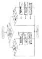
【0203】
例えば、建設機械独自の制御機器の例として、車体情報モニタ装置26と稼動情報モニタ装置27で管理・記録されている情報をオペレータに提供する多機能表示装置54を追加する場合、通常、建設機械用のこの種の表示装置54は独自通信規格に沿ったインターフェースを備えていることから、例えば図31に示すようにそのまま独自規格の通信ライン39上に接続すれば足りる。これによって機能追加時の工数低減が図れる効果もある。
【0204】
一方、共通規格の通信ライン40側でも、例えばGPS装置を用いて油圧ショベルの車体の位置情報を稼動情報モニタ装置46に記録したい場合、共通通信規格に沿ったインターフェースを備えた汎用のGPS装置55を図32に示すように共通規格の通信ライン40に接続するとともに、通信中継制御装置100と稼動情報モニタ装置46において位置情報を処理できるようにソフトウェアを変更するだけでよく、汎用規格側についても優れた拡張性を得ることができる。なおこの場合も機能追加時の工数低減が図れることは言うまでもない。
【0205】
▲4▼モデルチェンジ等への追従性
さらに、例えば原動機14のモデルチェンジ等によりそれまで搭載していた汎用通信規格のインターフェースがそれまでとは異なる通信規格のインターフェースに変更された場合あるいは汎用通信規格自体に変更が加えられた場合、例えば前述の特公平8−28911号公報のように全ての制御装置に同一の通信規格のインターフェースを備える構成の場合、原動機制御装置のみならず他の全ての制御装置も一斉にインターフェースの変更を余儀なくされ、開発効率の低下、開発コストの増大等に繋がる。これに対して本実施形態によれば、上記のように共通通信規格に沿った通信ライン40と独自通信規格に沿った通信ライン39との2系統に分けていることにより、上記のように通信規格が変更された場合等でも独自の通信規格に沿った通信ライン39側には全く影響が及ばないので、通信規格の変更による制御装置のソフトおよびハードの変更を最小限に抑えることができる。
【0206】
本発明の第2の実施形態を図33〜図36により説明する。本実施形態は、各制御装置及びモニター装置からの通信データを一元管理できる機能を持つ通信管理制御装置100′を設けた実施形態である。第1の実施形態と同等の部分には同一の符号を付し、適宜説明を省略する。
【0207】
図33は、本発明の第2の実施形態による油圧ショベルの電子制御システムを、油圧ショベル及びこれに搭載される油圧システムと共に示す図であり、先の第1の実施形態の図1に相当する図である。この図33において、本実施形態では、第1の実施形態の通信中継制御装置100にデータベース(後述)を設けることにより、各制御装置及びモニター装置からの通信データを一元管理できる機能を持つ通信管理制御装置100′としたものである。
【0208】
図34は、その通信管理制御装置100′の機能的構成を表す機能ブロック図である。この図34において、先の図7に示した上記通信中継制御装置100と異なる点は、先の第1の実施形態と同様にして共通規格の通信ライン40を介し受信するガバナ制御装置17等からの通信データ及び独自規格の通信ライン39を介し受信する制御装置23,33及びモニタ装置45,46からの通信データを格納するデータベース101を備えた主記憶装置105を設けたことと、先の図6に示した稼動情報モニタ装置46の外部通信制御部4601とほぼ同様の機能を備えた外部通信制御部108を設けたことである。これにより、通信管理制御装置100′は、共通規格の通信ライン40および独自規格の通信ライン39上を流れる全通信データの集積管理機能を備えることができる。
【0209】
すなわち、詳細な説明を省略するが、本実施形態では、通信管理制御装置100′の通信制御部107及び106は、共通規格の通信ライン40上を流れる通信データパケットおよび独自規格の通信ライン39上を流れる通信データパケットを常に監視してそれら全てを取得し、各々の通信規格の様式に従ってデータパケットからデータを抽出し、それら全データを通信規格に依らない様式でデータベース101に逐次保存する。
【0210】
そして、それら保存されたデータの中から、各制御装置17,23,33又はモニタ装置45,46が受信したいデータに関する送信要求を通信ライン39,40を介して通信制御部107又は106に送信し、これに応じてCPU102がその送信を要求した側の通信規格にデータ変換した後、通信制御部106又は107から通信ライン40,39を介して送信する。
【0211】
一例として、ガバナ制御装置17から送信したエンジン油圧Poilをデータベース101に格納後、変換して稼働情報モニタ装置46にて受信する場合を例にとり図35及び図36により説明する。
【0212】
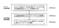
図35は、ガバナ制御装置17及び通信管理制御装置100′相互間のデータ通信の概略処理手順を表す図であり、図36は、通信管理制御装置100′及び稼働情報モニタ装置46相互間のデータ通信の概略処理手順を表す図である。
【0213】
図35において、まず、ガバナ制御装置20が、エンジン油圧データPoilを含むデータパケットを共通規格の通信ライン40上に一定周期で出力する(STEP2101)。
【0214】
これに応じて、通信管理制御装置100′は、共通規格の通信ライン40からエンジン油圧データPoilを含むデータパケットを取得(STEP2102)した後、取得したデータパケットからエンジン油圧データPoilを抽出し、データベース101に格納する(STEP2103)。
【0215】
次に、図36において、稼動情報モニタ装置46が、エンジン油圧データPoilの送信要求を含むデータパケットを独自規格の通信ライン39上に一定周期で出力する(STEP2201)。
【0216】
これに応じて、通信管理制御装置100′は、独自規格の通信ライン39からエンジン油圧データPoilの送信要求を含むデータパケットを取得(STEP2202)した後、取得したデータパケットからエンジン油圧データPoilの送信要求を抽出する(STEP2203)。その後、データベース101に上記STEP2103にて格納してあったエンジン油圧データPoilデータを独自通信規格の様式に変換し、その様式に従ってデータパケット化する(STEP2204)。そして、独自規格の通信ライン39にエンジン油圧データPoilを含む変換後のデータパケットを出力する(STEP2205)。
【0217】
これに応じて、稼動情報モニタ装置46は、独自規格の通信ライン39上からエンジン油圧データPoilを含むデータパケットを取得(STEP2206)した後、取得したデータパケットからエンジン油圧データPoilを抽出する(STEP2207)。
【0218】
以上のようにして、独自規格の通信ライン39及び共通規格の通信ライン40上を流れるすべてのデータは、通信管理制御装置100内のデータベース101にいったん格納され集積される。その後、各制御装置17,23,33及びモニタ装置45,46からの送信要求に応じてその送信側に対応する通信規格様式に変換され、対応する通信ライン39又は40へと送信される。
【0219】
上記において、通信管理制御装置100′の行う図35に示したSTEP2102及びSTEP2103が、請求項2記載の2系統の通信ラインから受信した通信データを一旦格納する格納手段を構成し、STEP2204及びSTEP2205が、2系統の通信ラインのうち一方の通信ラインから受信され格納手段に格納された通信データに関する送信要求が他方の通信ラインを介して受信されたとき、その格納されている通信データを他方の通信ラインの通信規格に沿うように変換して出力する変換手段を構成する。
【0220】
本実施形態によれば、上記第1の実施形態と同様の効果に加え、以下のような効果を奏する。
【0221】
すなわち、通信管理制御装置100′は、上述したようにして複数の制御装置17,23,33やモニタ装置45,46等からの通信データをすべて集約して格納し一元管理することが可能となる。したがって、図35及び図36を用いて上述したように、通信管理制御装置100′を介しデータ送信側の処理とデータ受信側の処理を独立させることができる。すなわちデータ送信側は自らの通常の制御周期の中でデータを通信管理制御装置側に送信すれば足り(上記図35のSTEP2101〜STEP2103参照)、データ受信側は自らの通常の制御周期の中でデータ送信要求を通信管理制御装置側に送信し通信管理制御装置からデータを受け取るだけで足りる(上記図35のSTEP2201〜STEP2203参照)。この結果、各制御装置17,23,33及びモニタ装置45,46における処理ステップ数を減少することができるとともに、例えばデータ送信側でデータ受信側からのデータ送信要求の割り込みに応じる形でデータを送信する必要は全くなくなる(先の第1実施形態で説明した(2)送信要求指令に応じた送受信におけるエンジン油圧Poil又はエンジン冷却水温Twの例を参照)ので、送信要求割り込み発生による処理低下を防ぐことができる。またデータ受信側ではデータ送信要求を送ってから実際にデータが送られてくるまでの遅れ時間が短縮されるので通信データ待ちによる処理低下を防ぐことができる。以上のようにして、各制御装置17,23,33及びモニタ装置45,46における通信処理負担及び制御処理負担を大きく低減することができる。
【0222】
また、上記第1の実施形態では、車体情報モニタ装置45及びガバナ制御装置17が出力した信号を通信ライン39,40を介して稼動情報モニタ装置46で受信し所定の処理を行うことで、油圧ショベル1の稼動時間、稼動状態等を記憶しておき、メンテナンスの際に稼働情報データや故障情報データを収集したいときは、メンテナンス作業者がパーソナルコンピュータ(PC)53等の外部機器をモニタ装置46に接続してそれら情報データ及び故障情報データを出力するようにしていた。この場合、モニタ装置46に一旦取り込み記憶させてから出力させる必要があるとともに、モニタ装置46に取り込まれないデータ・情報については別途各制御装置17,23,33及びモニタ装置45ごとに例えば情報端末との接続インタフェースを予め設けておき、パソコン53等を個別に接続してデータを吸い上げる必要があった。
【0223】
これに対して、本実施形態においては、上記のように通信管理制御装置100′ですべてのデータをデータベース101にて一極管理しているため、上記のような外部へのデータ取り出しにおける煩雑さを生じることなく、前述のように通信管理制御装置100′の外部通信制御部108にパソコン53等を接続しデータベース101に格納されている情報を一括して読み込めば足りる(図33や図34における2点鎖線のパソコン53の図示参照)。したがって、メンテナンス作業の大幅な省力化を図れるとともに、各制御装置ごとに情報端末との接続インターフェースを設ける必要がなくなり、コスト低減を図れる。
【0224】
なお、以上の第1及び第2の実施形態では、データ通信のための共通バスとして、独自通信規格に沿った通信ライン39と共通通信規格に沿った通信ライン40の2系統の共通通信ラインを設けたが、制御データあるいはモニタデータが増加した場合は、通信ライン39あるいは通信ライン40の数を増やし、3系統以上の共通通信ラインとしてもよい。また、通信データの種類として制御データとモニタデータの2種類について述べたが、音響機器その他の付帯設備を搭載した油圧ショベルにあっては、それらのオーディオデータやスイッチ系統のデータを共通規格の通信ライン40側を用いて通信してもよい。
また、以上においては、建設機械の例として油圧ショベルを例にとって説明したが、これに限られず、手動操作レバーを用いて操作するものであれば他の建設機械、例えばクローラクレーン、ホイールローダ等に対しても適用でき、この場合も同様の効果を得る。
【0225】
【発明の効果】
請求項1記載の発明によれば、汎用通信ラインと専用通信ラインの2系統構成とすることにより、原動機制御装置側では従来通り例えば自動車業界の汎用の通信規格に沿ったインターフェースを備えた構成とする一方で、原動機制御装置以外の油圧機器制御装置等に係わる専用通信ライン側では、汎用の通信規格にとらわれることなく独自の専用通信規格とし、建設機械の制御・情報収集等に最適な通信データの内容・通信周期等を独自に定義して使用することができる。この結果、汎用通信規格に沿ったインターフェースを備える近年の建設機械に適用する場合であっても、十分な電子制御機能を発揮することができる。
【0226】
請求項2記載の発明によれば、通信管理制御装置は、複数の制御装置やモニタ装置等からの通信データをすべて集約して格納し一元管理することが可能となる。したがって、通信管理制御装置を介しデータ送信側の処理とデータ受信側の処理を独立させることができるので、各制御装置における通信処理負担及び制御処理負担を大きく低減することができる。
【図面の簡単な説明】
【図1】本発明の第1の実施形態による油圧ショベルの電子制御システムを、油圧ショベル及び油圧システムと共に示す図である。
【図2】図1に示したガバナ制御装置の機能的構成を示す機能ブロック図である。
【図3】図1に示した車体制御装置の機能的構成を示す機能ブロック図である。
【図4】図1に示した電気レバー制御装置の機能的構成を示す機能ブロック図である。
【図5】図1に示した車体情報モニタ装置の機能的構成を示す機能ブロック図である。
【図6】図1に示した稼動情報モニタ装置の機能的構成を示す機能ブロック図である。
【図7】図1に示した通信中継制御装置の機能的構成を表す機能ブロック図である。
【図8】第1の実施の形態における共通通信ラインの通信データを表形式で示す図である。
【図9】第1及び第2通信部の機能的構成を示す機能ブロック図である。
【図10】CPUのタイマ割り込み処理を説明するフローチャートである。
【図11】通信部のデータ送信処理を説明するフローチャートである。
【図12】通信中継制御装置が行う処理を表すフローチャートである。
【図13】通信部のデータ受信処理を説明するフローチャートである。
【図14】CPUの受信割り込み処理を説明するフローチャートである。
【図15】目標エンジン回転数データの通信の全体の流れを概略的にまとめた処理フローである。
【図16】CPUの送信要求割り込み処理を説明するフローチャートである。
【図17】エンジン油圧データの通信の全体の流れを概略的にまとめた処理フローである。
【図18】ガバナ制御装置のメイン処理を説明するフローチャートである。
【図19】車体制御装置のメイン処理を説明するフローチャートである。
【図20】電気レバー制御装置のメイン処理を説明するフローチャートである。
【図21】車体情報モニタ装置のメイン処理を説明するフローチャートである。
【図22】稼動情報モニタ装置のメイン処理の全体の流れを説明するフローチャートである。
【図23】稼動情報モニタ装置のメイン処理におけるエンジン稼動記録処理の詳細を説明するフローチャートである。
【図24】稼動情報モニタ装置のメイン処理によりEEPROMに記録されるデータの様子を示す図である。
【図25】稼動情報モニタ装置のメイン処理におけるエンジン油圧異常記録処理の詳細を説明するフローチャートである。
【図26】稼動情報モニタ装置のメイン処理におけるフィルタ圧力異常記録処理の詳細を説明するフローチャートである。
【図27】稼動情報モニタ装置のメイン処理における燃料残量警告記録処理の詳細を説明するフローチャートである。
【図28】稼動情報モニタ装置のメイン処理における冷却水温頻度分布記録処理の詳細を説明するフローチャートである。
【図29】第3通信部の機能的構成を示す機能ブロック図である。
【図30】稼動情報モニタ装置のメイン処理におけるPC通信処理の詳細を説明するフローチャートである。
【図31】独自規格通信ライン側に建設機械用の表示装置を接続した変形例を表す図である。
【図32】共通規格通信ライン側に汎用GPS装置を接続した変形例を表す図である。
【図33】本発明の第2の実施形態による油圧ショベルの電子制御システムを、油圧ショベル及びこれに搭載される油圧システムと共に示す図である。
【図34】図33に示した通信管理制御装置の機能的構成を表す機能ブロック図である。
【図35】ガバナ制御装置及び通信管理制御装置相互間のデータ通信の概略処理手順を表す図である。
【図36】通信管理制御装置及び稼働情報モニタ装置相互間のデータ通信の概略処理手順を表す図である。
【符号の説明】
1 油圧ショベル(建設機械)
2 下部走行体(作業装置)
3 上部旋回体(作業装置)
7 掘削作業装置(作業装置)
11 油圧シリンダ(油圧機器)
12 油圧シリンダ(油圧機器)
13 油圧シリンダ(油圧機器)
14 原動機(油圧機器)
17 ガバナ制御装置(特定の制御装置、原動機制御装置)
18 油圧ポンプ(油圧機器)
23 車体制御装置(特定のもの以外の制御装置、油圧機器制御装置)
24,25,26 制御弁
27,28,29 操作レバー
33 車体制御装置(特定のもの以外の制御装置、油圧機器制御装置)
39 独自通信規格の通信ライン(専用通信ライン)
40 共通通信規格の通信ライン(汎用通信ライン)
41 油圧センサ
42 水温センサ
43 燃料レベルセンサ
44 圧力センサ
45 車体情報モニタ装置
46 稼動情報モニタ装置
47 表示装置
100 通信中継制御装置
100′通信管理制御装置[0001]
BACKGROUND OF THE INVENTION
The present invention relates to an electronic control system for a construction machine that connects a plurality of control devices that control a prime mover, hydraulic equipment, and the like of a construction machine to each other via a common communication line, and configures a network to transmit and receive data.
[0002]
[Prior art]
In recent years, there is a great demand for construction machines for performance improvement or versatility, and electronic control is progressing to meet such demands. For this reason, the electronic control system related to this requires high-speed computation, and the use of a high-performance microcomputer is inevitable. As a result, problems such as an increase in manufacturing cost and complication of control devices and wire harnesses due to an increase in input / output signals of the system are occurring.
[0003]
In order to deal with this problem, the control function of the construction machine to be controlled is divided into functional units, and a control device (control unit) is provided for each functional unit. It has been studied to decentralize control devices that perform the above control. For example, in Japanese Patent Publication No. 8-28911, a control device is provided for each device such as an engine control device and a pump control device, and the control devices are connected by a single multiplex transmission serial communication circuit. An electronic control system for a construction machine is disclosed in which a network capable of bidirectional communication is configured to facilitate system expansion.
[0004]
[Problems to be solved by the invention]
The prior art has the following problems.
[0005]
In general, a motor (engine) mounted on a construction machine as a drive source and an engine control device for controlling the same are used for ordinary automobiles (trucks, etc.) from the viewpoint of improving productivity and reducing costs. There are many cases.
[0006]
Here, in the automobile manufacturing industry, as described above, electronic control has been advanced for a long time in advance of construction machines due to demands for performance improvement and the like. For example, with respect to engine control, a common communication standard SAE J1939, which has been standardized mainly for the purpose of fault diagnosis, has been formulated, and an engine control apparatus having an interface in accordance with this general-purpose communication standard is used. Accordingly, in recent construction machines, an engine and an engine control device having an interface conforming to the general-purpose communication standard in the automobile industry are often used.
[0007]
When the above prior art is applied to such a recent construction machine, as described above, all control devices are connected to a single multiplex transmission serial communication line and communicate with each other. All other control devices other than the above need to be provided with an interface conforming to the general-purpose communication standard in the same manner as the engine control device.
[0008]
However, in this case, for example, the following inconvenience occurs.
[0009]
(1) Inconvenience related to communication data identifiers
That is, the general-purpose communication standard is originally defined for automobiles, particularly for the purpose of failure diagnosis, and therefore many communication data identifiers are allocated and reserved in advance for use in automobiles. However, many of these communication data identifiers are unnecessary for construction machinery, and conversely, there is a shortage of those necessary for construction machinery. Although it is allowed to assign unique communication data to surplus identifiers, the number of surplus identifiers themselves is small because the number of data identifiers is limited and many of them are already assigned. For this reason, there is not enough room for newly adding unique data necessary for the construction machine during data communication.
[0010]
(2) Inconvenience related to communication speed
As described in (1) above, the general-purpose communication standard is originally specified for automobiles. However, the construction machine is not only a traveling mechanism similar to that of an automobile and its control system, but also a hydraulic drive system that drives them to a mechanism such as a front device composed of a boom, an arm, a bucket, etc. in a hydraulic excavator, Furthermore, there are control systems for controlling them, and the amount of communication data required for control is enormous compared to automobiles. For this reason, when the general-purpose communication standard is used, the enormous amount of data cannot be sufficiently communicated at the specified communication speed, and the communication amount is insufficient for electronic control of construction machines. Resulting in.
[0011]
As described above with reference to examples (1) and (2), the prior art described above cannot function sufficiently for electronic control of recent construction machines.
[0012]
An object of the present invention is to provide an electronic control system for a construction machine capable of exhibiting a sufficient electronic control function even for a recent construction machine having an interface conforming to a general-purpose communication standard.
[0013]
[Means for Solving the Problems]
(1) In order to achieve the above object, the present invention includes a prime mover, a plurality of work devices, and a plurality of hydraulic devices that generate hydraulic power using the driving force of the prime mover to drive the work devices. A prime mover control device for controlling the prime mover provided in the construction machine and the hydraulic equipment is controlled.plural Hydraulic equipment control equipmentPlace In an electronic control system of a construction machine that has a plurality of control devices including, connects these plurality of control devices to each other and transmits and receives data,A general-purpose communication line provided as a common bus for data communication, to which at least the prime mover control device is connected A general-purpose communication line that supports interfaces in accordance with general-purpose communication standards;A dedicated communication line provided as a common bus for data communication, The pluralityHydraulic equipment Control deviceBut Connected,It is possible to directly send and receive data between the plurality of hydraulic equipment control devices, A dedicated communication line corresponding to an interface conforming to a dedicated communication standard different from the general-purpose communication standard, and connected to the general-purpose communication line and the dedicated communication line. From one of these two communication lines, A communication relay control device that converts received communication data to conform to the communication standard of the other communication line and transmits the communication data to the other communication line;The prime mover control device and the plurality of hydraulic equipment control devices have a function of transmitting data at a predetermined communication cycle set for each type of data, and the communication relay control device further includes the two systems. When communication data received from one of the communication lines is converted and transmitted so as to conform to the communication standard of the other communication line, the transmission cycle of the data does not depend on the communication standard and the predetermined communication A cycle is maintained, and the communication data is transmitted to the other communication line in the communication cycle. .
[0014]
In the present invention, a plurality of control devices are used.Chihara The motivation control device is connected to a general-purpose communication line corresponding to an interface in accordance with a general-purpose communication standard,Multiple hydraulic equipment controllers Is connected to a dedicated communication line corresponding to an interface according to a dedicated communication standard different from the general-purpose communication standard. A communication relay control device is provided for data communication between communication lines of different standards, thereby converting the communication data received from one communication line to conform to the communication standard of the other communication line and transmitting To do.The prime mover control device and the plurality of hydraulic equipment control devices have a function of transmitting data at a predetermined communication cycle set for each type of data, and the communication relay control device is one of the two communication lines. When the communication data received from one communication line is converted and transmitted so as to conform to the communication standard of the other communication line, the data transmission cycle is maintained regardless of the communication standard, and the predetermined communication cycle is maintained. Send data to the other communication line in the communication cycle .
[0015]
like thisStructure As a result, the prime mover control device side is configured to have an interface that conforms to general-purpose communication standards in the automobile industry, for example, while the dedicated communication line side is associated with hydraulic equipment control devices other than the prime mover control device. Therefore, it is possible to define and use communication data content / communication cycle that is optimal for construction machine control, information collection, etc., independently of the general-purpose communication standard. As a result, in the present invention, a sufficient electronic control function can be exhibited even when applied to a recent construction machine equipped with an interface conforming to a general-purpose communication standard.
[0016]
In order to achieve the above object, the present invention provides a construction machine comprising a prime mover, a plurality of work devices, and a plurality of hydraulic devices that generate hydraulic power using the driving force of the prime mover to drive the work devices. A prime mover control device for controlling the prime mover and the hydraulic equipmentplural Hydraulic equipment control equipmentPlace In an electronic control system of a construction machine that has a plurality of control devices including, connects these plurality of control devices to each other and transmits and receives data,A general-purpose communication line provided as a common bus for data communication, to which at least the prime mover control device is connected A general-purpose communication line that supports interfaces in accordance with general-purpose communication standards;A dedicated communication line provided as a common bus for data communication, wherein the plurality of hydraulic equipment control devices are connected, and data can be directly transmitted and received between the plurality of hydraulic equipment control devices. , A dedicated communication line corresponding to an interface conforming to a dedicated communication standard different from the general-purpose communication standard, and the communication data received from the two communication lines connected to the general-purpose communication line and the dedicated communication line.In a format that does not depend on communication standards Storage means for once storing, and when a transmission request regarding communication data received from one of the two communication lines and stored in the storage means is received via the other communication line, the storage A communication management control device having conversion means for converting the communication data being converted to the communication standard of the other communication line and outputting the communication data.The prime mover control device and the plurality of hydraulic equipment control devices transmit a data transmission request at a predetermined cycle and a first communication function that transmits data at a predetermined communication cycle set for each data type. The data transmission side of the prime mover control device and the plurality of hydraulic equipment control devices transmits data to the communication management control device at the predetermined communication cycle by the first communication function, and the prime mover control The data receiving side of the apparatus and the plurality of hydraulic equipment control devices transmits a data transmission request to the communication management control device by the second communication function and receives data from the communication management control device. Do .
[0017]
As a result, the communication management control device can collect and store all communication data from a plurality of control devices, monitor devices, and the like for centralized management. Therefore, the processing on the data transmission side and the processing on the data reception side can be made independent through the communication management control device. In other words, it is sufficient for the data transmission side to transmit data to the communication management control device side in its normal control cycle, and the data reception side sends a data transmission request to the communication management control device side in its normal control cycle. It is only necessary to transmit and receive data from the communication management control device. As a result, the number of processing steps in each control device can be reduced. Further, for example, the data transmission side does not need to transmit data at all in response to the data transmission request interrupt from the data reception side, so that it is possible to prevent a decrease in processing due to the transmission request interrupt occurrence. In addition, since the delay time from when a data transmission request is sent to when data is actually sent is shortened at the data receiving side, it is possible to prevent a decrease in processing due to waiting for communication data. As described above, the communication processing load and the control processing load in each control device can be greatly reduced.
[0018]
(3) Preferably, in the above (1) or (2), the plurality of control devices include both the prime mover control device and the hydraulic equipment control device, and the general-purpose communication line is connected to the prime mover control device. The dedicated communication line is connected to the hydraulic equipment control device.
[0019]
(4) Preferably, in any one of the above (1) to (3), at least one monitor device connected to the dedicated communication line for monitoring the operation status of the construction machine is provided.
[0020]
(5) Preferably, in any one of the above (1) to (4), the apparatus further includes a plurality of sensors for detecting a state quantity related to an operation state of the construction machine, and the control device or the monitor device At least one has a collecting means for collecting a detection signal from the sensor.
[0021]
(6) More preferably, in the above (5), the control device or monitor device that collects the detection signal creates operation information data or failure information data of each part of the construction machine based on the collected detection signal. Information preparation means is provided.
[0022]
DETAILED DESCRIPTION OF THE INVENTION
Hereinafter, embodiments of the present invention will be described with reference to the drawings.
[0023]
A first embodiment of the present invention will be described with reference to FIGS.
[0024]
FIG. 1 is a diagram showing an electronic control system for a hydraulic excavator according to a first embodiment of the present invention, together with the hydraulic excavator and a hydraulic system mounted thereon. In FIG. 1,
[0025]
The excavation work device 7 includes a
[0026]
The
[0027]
The
[0028]
The
[0029]
The
[0030]
The
[0031]
The
[0032]
The operation signals X1, X2, and X3 are input to the electric
[0033]
The
[0034]
Further, sensors for monitoring the state of each device of the
[0035]
In addition, the electronic control system is provided with an operation information monitor
[0036]
The most important feature of the present embodiment is that it is connected to the vehicle
[0037]
The
[0038]
The
[0039]
The
[0040]
FIG. 2 is a functional block diagram showing a functional configuration of the
[0041]
FIG. 3 is a functional block diagram showing a functional configuration of the vehicle
[0042]
FIG. 4 is a functional block diagram illustrating a functional configuration of the electric
[0043]
FIG. 5 is a functional block diagram showing the configuration of the vehicle body information monitor
[0044]
FIG. 6 is a functional block diagram showing a functional configuration of the operation information monitor
[0045]
FIG. 7 is a functional block diagram illustrating a functional configuration of the communication
[0046]
Next, communication using the
FIG. 8 is a diagram illustrating an example of data communicated via the
[0047]
As shown in FIG. 8, the communication data of the control system includes communication after the target engine speed Nr and the actual engine speed Ne are transmitted from the
[0048]
On the other hand, as the communication data of the monitor system, the actual engine speed Ne, the engine oil pressure Poil, and the engine cooling water temperature Tw are transmitted from the
[0049]
At this time, the “cycle” shown in the figure indicates an interval at which the control device or the monitor device that receives the data wants to use the data, that is, a time interval at which the data is to be updated. This period is determined in view of the speed at which the data is required for control or monitoring or the data changes. For example, the target rotational speed Nr of the
[0050]
FIG. 9 is a functional block diagram illustrating an example of the configuration of the
[0051]
Although not described in detail, the
[0052]
Next, details of the data transmission / reception method will be described. As described with reference to FIG. 8, each data needs to be transmitted according to a predetermined cycle required by the receiving side, and the cycle varies greatly from about 10 msec to about 1 sec depending on the data. Therefore, in the present embodiment, data transmission / reception with a period of 10 to 100 msec, that is, the target engine speed Nr and the actual engine speed Ne communicated with the
[0053]
On the other hand, data transmission / reception of the remaining
[0054]
(1) Automatic transmission / reception at specified intervals (with conversion)
First, the automatic transmission / reception method for each period will be described. As an example, a case where the target engine speed Nr is communicated from the
[0055]
(1-1) Transmission
The
[0056]
STEP5010:
A counter provided for each data is incremented (+1). In other words, each counter is updated each time a timer interrupt occurs in this STEP. For example, if a timer interrupt is executed every 1 msec, each counter is updated every 1 msec.
[0057]
STEP5020:
Next, it is determined whether the value of each counter coincides with the transmission cycle for each data shown in FIG. If they do not match, the timer interrupt process is terminated and the process returns to the main process. If it is determined in
[0058]
STEP5030:
Clear (0) the counter value of the data with the same period.
[0059]
STEP5040:
The transmission data having the same period is written in the storage location corresponding to the ID No. on the
[0060]
STEP5050:
In order to cause the
[0061]
When the processing of the
[0062]
STEP6010:
It is monitored whether the transmission request flag in the
[0063]
STEP6020:
The data at the storage location in the
[0064]
STEP6030:
An ID corresponding to the storage location is added to the read data.
[0065]
STEP 6040:
The vacant state of the
[0066]
STEP6050:
The data with the ID added is converted into time-series serial data to form a data packet, which is transmitted to the
[0067]
STEP 6060:
The transmission request flag in the
[0068]
(1-2) Relay and conversion
Next, a data relay and conversion method in the communication
FIG. 12 is a flowchart showing processing performed by the communication
[0069]
STEP6510:
The second communication control unit 107 reads a data packet including all data transmitted from the common
[0070]
STEP6520:
The second communication control unit 107 extracts the read data packet whose ID number is preset by the
[0071]
STEP6530:
The
[0072]
STEP 6540:
The
[0073]
STEP 6550:
The first
[0074]
STEP 6560:
The first
[0075]
(1-3) Reception
Finally, a data reception method in the vehicle
[0076]
STEP 7010:
A data packet including all data transmitted from the
[0077]
STEP7020:
Among the read data packets, those whose ID numbers are preset in the
[0078]
STEP 7030:
An ID No is taken from the extracted data and written to a storage location in the
[0079]
STEP 7040:
In order to notify the
[0080]
The
[0081]
STEP8010:
Data is read from a predetermined storage location corresponding to IDNo on the
[0082]
STEP8020:
The reception interrupt flag in the
As described above, for example, the target engine speed Nr transmitted every 50 msec by the
[0083]
The above description has been made by taking the target engine speed Nr transmitted from the
[0084]
Further, the above description has been made by taking the data communication of the
[0085]
(2) Transmission / reception according to the transmission request command (with conversion)
The above (1) has been described by taking as an example a case where transmission is automatically performed at predetermined intervals from the transmission side. However, as described above, the
[0086]
FIG. 16 is a flowchart showing this transmission request interrupt processing program, and the same steps as those in FIG. 10 are denoted by the same reference numerals. In this case, although detailed description and illustration are omitted, an engine for the
[0087]
When the transmission request command signal is received in this way, the interrupt processing program shown in FIG. 16 is started. First, in
[0088]
Thereafter, in
[0089]
In this way, this interrupt process is performed every 1 second in the communication cycle, and
[0090]
When the above processing of the
[0091]
FIG. 17 is a processing flow in which the overall communication flow of the engine hydraulic pressure Poil is summarized as STEP 1501 to STEP 1514.
[0092]
(3) Transmission / reception without conversion
In any of the above (1) and (2), after conversion corresponding to the standard is performed by the communication
[0093]
In this case, as in the above (1), the operation signals X1, X2, and X3 communicated with the electric
[0094]
Further, the filter pressure Pflt and the fuel level Fuel communicated with the
[0095]
Next, the main processing of each
[0096]
First, the main process of the
[0097]
FIG. 18 is a flowchart showing a control program stored in the
[0098]
STEP1701:
Constants necessary for the control calculation are read from the
[0099]
STEP1702:
Via the A / D converter, signals of the target rotational speed Nr, engine oil pressure Poil, and cooling water temperature Tw from the
[0100]
STEP 1703:
A signal of the actual rotational speed Ne of the
[0101]
STEP 1704:
A control signal R is output to the
[0102]
Returning to
[0103]
Next, main processing of the vehicle
[0104]
FIG. 19 is a flowchart showing a control program stored in the
[0105]
STEP2301:
Constants necessary for the control calculation are read from the
[0106]
STEP 2302:
Each signal of the discharge pressure Pd from the
[0107]
STEP 2303:
As described above, the load state of the
[0108]
STEP 2304:
The pressure oil discharge amount required for the
[0109]
STEP 2305:
Based on the required discharge amount of the hydraulic pump calculated in advance, the engine load state and the discharge amount that the hydraulic pump can perform are calculated from Pd, and the target tilt angle θr is calculated from the discharge amount.
[0110]
STEP 2306:
A control signal is output to the swash plate
[0111]
Returning to
[0112]
Next, main processing of the electric
[0113]
FIG. 20 is a flowchart showing a control program stored in the
[0114]
STEP3301:
Constants necessary for control calculation are read from the
[0115]
STEP3302:
The operation signals X1, X2, and X3 from the operation levers 27, 28, and 29 are read via the A /
[0116]
STEP 3303:
The valve operation amount is calculated according to the operation signals X1, X2, and X3.
[0117]
STEP 3304:
An operation command is output to the
[0118]
Next, main processing of the vehicle body
[0119]
FIG. 21 is a flowchart showing a control program stored in the
[0120]
STEP4501:
Each signal of the filter pressure Pflt and the fuel level Fuel is input via the A /
[0121]
STEP4502:
Clogging is determined from the filter pressure, and an alarm signal Wflt is set.
[0122]
STEP4503:
As described above, the actual rotational speed of the
[0123]
Return to STEP4501.
[0124]
Next, the main process of the operation information monitor
[0125]
FIG. 22 is a flowchart showing a control program stored in
[0126]
First, when the
[0127]
Next, the engine operation recording process of
[0128]
STEP 9101:
First, it is determined whether the actual rotational speed (engine speed) Ne of the
[0129]
STEP9102:
If the engine speed Ne is greater than the operation determination speed N0, it is determined whether or not the engine operation flag indicating whether or not the
[0130]
STEP9103:
The engine operation flag is turned on to indicate that the
[0131]
STEP 9104:
Current time is read from RTC4603.
[0132]
STEP 9105:
The engine start time is recorded in the
[0133]
STEP 9106:
On the other hand, if it is determined in
[0134]
STEP 9107:
The engine operation flag is turned off to indicate that the engine has stopped.
[0135]
STEP 9108:
Current time is read from RTC4603.
[0136]
STEP 9109:
The engine stop time is recorded in the
[0137]
STEP 9110:
Next, the latest engine start time stored in the engine operation record of the
[0138]
STEP9111:
Next, the engine accumulated operation time stored in the
[0139]
When
[0140]
STEP9201:
First, it is determined whether the
[0141]
STEP9202:
As described above, it is determined whether the engine oil pressure Poil received from the
[0142]
STEP 9203:
If it is determined in
[0143]
STEP 9204:
Turn on the engine oil pressure abnormality flag.
[0144]
STEP9205:
Read the current time from RTC4603.
[0145]
STEP 9206:
The
[0146]
When this operation information monitor
[0147]
STEP 9207:
On the other hand, if it is determined in
[0148]
STEP 9208:
Turn off the engine oil pressure abnormality flag.
[0149]
STEP 9209:
Read the current time from RTC4603.
[0150]
STEP9210:
The
[0151]
As described above, every time an abnormality in the engine hydraulic pressure occurs or is canceled, it is recorded in the
[0152]
When
[0153]
STEP 9301:
First, it is determined whether the
[0154]
STEP9302:
It is determined whether the filter pressure Pflt received directly from the vehicle body
[0155]
STEP 9303:
If it is determined in
[0156]
STEP 9304:
Set the filter pressure error flag to ON.
[0157]
STEP 9305:
Read the current time from RTC4603.
[0158]
STEP 9306:
The
[0159]
When the operation information monitor
[0160]
STEP 9307:
On the other hand, if it is determined in
[0161]
STEP 9308:
Set the filter pressure error flag to OFF.
[0162]
STEP 9309:
Read the current time from RTC4603.
[0163]
STEP9310:
As shown in FIG. 24, the
[0164]
As described above, every time when the abnormality of the filter pressure is generated or canceled, it is recorded in the
[0165]
When
[0166]
STEP 9401:
It is determined whether the fuel level Fuel directly received from the vehicle body
[0167]
STEP 9402:
If it is determined in
[0168]
STEP 9403:
Turn on the remaining fuel warning flag.
[0169]
STEP9404:
Read the current time from RTC4603.
[0170]
STEP 9405:
As shown in FIG. 24, the remaining time of the remaining fuel warning is stored in the
[0171]
When the operation information monitor
[0172]
STEP 9406:
On the other hand, if it is determined in
[0173]
STEP 9407:
Turn off the remaining fuel warning flag.
[0174]
STEP 9408:
Read the current time from RTC4603.
[0175]
STEP 9409:
As shown in FIG. 24, the remaining fuel amount warning release time is stored in the EEPROM 4601 in the form of “year, month, day, hour, minute OFF” in the storage location of the remaining fuel amount warning in the EEPROM. Then, block 9400 ends.
[0176]
As described above, every time the warning of the remaining fuel amount is generated or canceled, it is recorded in the
[0177]
When
[0178]
STEP 9501:
First, it is determined whether the
[0179]
STEP 9502-9505:
As described above, the cooling water temperature Tw received through the
(1) Tw ≧ Tmax
(2) Tmax> Tw ≧ T2
(3) T2> Tw ≧ T1
(4) T1> Tw ≧ T0
(5) T0> Tw
To which of the five areas is applicable. As a result of the judgment,
(1) Tw ≧ Tmax ... Go to STEP9507
(2) Tmax> Tw ≧ T2... To
(3) T2> Tw ≧ T1... To
(4) T1> Tw ≧ T0 to STEP9510
(5) T0> Tw ... Go to STEP9506
Proceed with the process.
[0180]
STEP 9506-9510:
As shown in the water temperature frequency distribution of FIG. 24, the processing period Δt time (unit: mS, for example) of the
[0181]
As this process continues, the cooling water temperature time is accumulated in the storage location of the water temperature frequency distribution as shown in FIG. 24, and the temporal frequency distribution of the cooling water temperature is recorded. In the example of FIG.
(1) Tw ≧ Tmax… 10 hr
(2) Tmax> Tw ≧ T2 ... 190 hr
(3) T2> Tw ≧ T1 ... 310hr
(4) T1> Tw ≧ T0 ... 520 hr
(5) T0> Tw ... 220hr
It can be seen that 520 hr is in the range of T1> Tw ≧ T0 in the engine accumulated operating time 1250 hr.
[0182]
The determination values Tmax, T2, T1, and T0 used here may be set for each machine body type. For example, Tmax may be determined as a design overheat temperature, T0 may be a freezing point temperature of 0 ° C., and others may be determined as a value obtained by equally dividing T0 from Tmax.
[0183]
The
[0184]
When
[0185]
FIG. 29 is a functional block diagram showing the internal configuration of the external communication control unit 4601 of the operation information monitor
[0186]
Communication with the
[0187]
STEP 9601:
First, it is determined whether a command (character code) is received from the
[0188]
STEP 9602-9606:
Interpret the character code as a command. These processes are as follows.
[0189]
(1) STEP 9602:
Command (character code) is "T" ... Go to
(2) STEP 9603:
Command (character code) is "E" ... Go to
(3) STEP 9604:
The command (character code) is "P" ... Go to
(4) STEP 9605:
Command (character code) is "F" ... Go to STEP9610
(5) STEP 9606:
Command (character code) is "W" ... Go to STEP9611
(6) STEP 9606:
Command (character code) is other than “W”: block 9600 ends
STEP 9607-9611:
When the command is determined, in
[0190]
For example, if it is determined in
[0191]
The
[0192]
Thus, the
[0193]
When
[0194]
In the above, the excavation work device 7, the
[0195]
The
[0196]
Further, the common
[0197]
Further,
[0198]
According to the present embodiment configured as described above, the following effects are obtained.
[0199]
(1) Compatibility with recent construction machines in accordance with general-purpose communication standards
As described above, in the present invention, the
[0200]
By adopting such a configuration of the two-
[0201]
(2) Cost reduction
By dividing into two
[0202]
(3) Expandability as a system
By dividing into two
[0203]
For example, as an example of a control device unique to a construction machine, when a multi-function display device 54 that provides an operator with information managed and recorded by the vehicle body information monitor
[0204]
On the other hand, on the
[0205]
(4) Follow-up to model changes
Furthermore, for example, when the interface of the general-purpose communication standard that has been installed so far is changed to an interface of a communication standard different from that due to the model change of the
[0206]
A second embodiment of the present invention will be described with reference to FIGS. In the present embodiment, a communication
[0207]
FIG. 33 is a diagram showing an electronic control system for a hydraulic excavator according to the second embodiment of the present invention, together with the hydraulic excavator and the hydraulic system mounted thereon, and corresponds to FIG. 1 of the previous first embodiment. FIG. In FIG. 33, in this embodiment, by providing a database (described later) in the communication
[0208]
FIG. 34 is a functional block diagram showing a functional configuration of the communication
[0209]
That is, although detailed description is omitted, in the present embodiment, the
[0210]
Then, a transmission request relating to data that each
[0211]
As an example, the case where the engine oil pressure Poil transmitted from the
[0212]
FIG. 35 is a diagram showing a schematic processing procedure of data communication between the
[0213]
In FIG. 35, first, the
[0214]
In response to this, the communication
[0215]
Next, in FIG. 36, the operation
[0216]
In response to this, the communication
[0217]
In response to this, the operation
[0218]
As described above, all data flowing on the
[0219]
In the above, STEP 2102 and STEP 2103 shown in FIG. 35 performed by the communication
[0220]
According to the present embodiment, in addition to the same effects as those of the first embodiment, the following effects can be obtained.
[0221]
That is, the communication
[0222]
Further, in the first embodiment, the signals output from the vehicle body
[0223]
On the other hand, in the present embodiment, as described above, since all data is managed by the database 101 in the communication
[0224]
In the first and second embodiments described above, two common communication lines, that is, a
In the above, a hydraulic excavator has been described as an example of a construction machine. However, the present invention is not limited to this, and other construction machines such as a crawler crane and a wheel loader may be used as long as they are operated using a manual operation lever. The same effect can be obtained in this case as well.
[0225]
【The invention's effect】
According to the invention described in
[0226]
According to the second aspect of the present invention, the communication management control device can collect and store all communication data from a plurality of control devices, monitor devices, and the like for centralized management. Therefore, the data transmission side processing and the data reception side processing can be made independent through the communication management control device, so that the communication processing load and the control processing load in each control device can be greatly reduced.
[Brief description of the drawings]
FIG. 1 is a diagram showing an electronic control system for a hydraulic excavator according to a first embodiment of the present invention, together with the hydraulic excavator and the hydraulic system.
FIG. 2 is a functional block diagram showing a functional configuration of the governor control device shown in FIG. 1;
FIG. 3 is a functional block diagram showing a functional configuration of the vehicle body control device shown in FIG. 1;
4 is a functional block diagram showing a functional configuration of the electric lever control device shown in FIG. 1; FIG.
FIG. 5 is a functional block diagram showing a functional configuration of the vehicle body information monitoring device shown in FIG. 1;
6 is a functional block diagram showing a functional configuration of the operation information monitoring device shown in FIG. 1. FIG.
7 is a functional block diagram showing a functional configuration of the communication relay control apparatus shown in FIG. 1. FIG.
FIG. 8 is a diagram showing communication data of a common communication line in a tabular format in the first embodiment.
FIG. 9 is a functional block diagram showing a functional configuration of first and second communication units.
FIG. 10 is a flowchart for explaining CPU timer interrupt processing;
FIG. 11 is a flowchart illustrating data transmission processing of a communication unit.
FIG. 12 is a flowchart showing processing performed by the communication relay control apparatus.
FIG. 13 is a flowchart illustrating data reception processing of a communication unit.
FIG. 14 is a flowchart illustrating a reception interrupt process of a CPU.
FIG. 15 is a processing flow schematically summarizing the overall flow of communication of target engine speed data.
FIG. 16 is a flowchart illustrating CPU transmission request interrupt processing;
FIG. 17 is a processing flow schematically summarizing the overall flow of communication of engine oil pressure data.
FIG. 18 is a flowchart illustrating a main process of the governor control device.
FIG. 19 is a flowchart illustrating a main process of the vehicle body control device.
FIG. 20 is a flowchart illustrating a main process of the electric lever control device.
FIG. 21 is a flowchart illustrating a main process of the vehicle body information monitoring device.
FIG. 22 is a flowchart illustrating an overall flow of main processing of the operation information monitoring apparatus.
FIG. 23 is a flowchart illustrating details of an engine operation recording process in a main process of the operation information monitoring apparatus.
FIG. 24 is a diagram showing a state of data recorded in the EEPROM by the main process of the operation information monitoring apparatus.
FIG. 25 is a flowchart illustrating details of an engine oil pressure abnormality recording process in the main process of the operation information monitoring apparatus.
FIG. 26 is a flowchart illustrating details of a filter pressure abnormality recording process in the main process of the operation information monitoring apparatus.
FIG. 27 is a flowchart illustrating details of a remaining fuel amount warning recording process in the main process of the operation information monitoring apparatus.
FIG. 28 is a flowchart for explaining details of a coolant temperature frequency distribution recording process in the main process of the operation information monitoring apparatus.
FIG. 29 is a functional block diagram showing a functional configuration of a third communication unit.
FIG. 30 is a flowchart illustrating details of a PC communication process in the main process of the operation information monitoring apparatus.
FIG. 31 is a diagram showing a modification in which a display device for construction machines is connected to the unique standard communication line side.
FIG. 32 is a diagram illustrating a modification in which a general-purpose GPS device is connected to the common standard communication line side.
FIG. 33 is a diagram showing an electronic control system for a hydraulic excavator according to a second embodiment of the present invention, together with the hydraulic excavator and the hydraulic system mounted thereon.
34 is a functional block diagram showing a functional configuration of the communication management control apparatus shown in FIG. 33. FIG.
FIG. 35 is a diagram illustrating a schematic processing procedure of data communication between a governor control device and a communication management control device.
FIG. 36 is a diagram illustrating a schematic processing procedure of data communication between the communication management control device and the operation information monitoring device.
[Explanation of symbols]
1 Excavator (construction machine)
2 Lower traveling body (working device)
3 Upper swing body (working device)
7 Excavation work equipment (work equipment)
11 Hydraulic cylinder (hydraulic equipment)
12 Hydraulic cylinder (hydraulic equipment)
13 Hydraulic cylinder (hydraulic equipment)
14 prime mover (hydraulic equipment)
17 Governor control device (specific control device, prime mover control device)
18 Hydraulic pump (hydraulic equipment)
23 Car body control devices (control devices other than specified ones, hydraulic equipment control devices)
24, 25, 26 Control valve
27, 28, 29 Operation lever
33 Car body control devices (control devices other than specified ones, hydraulic equipment control devices)
39 Communication line of original communication standard (dedicated communication line)
40 Common communication standard communication line (general-purpose communication line)
41 Hydraulic sensor
42 Water temperature sensor
43 Fuel level sensor
44 Pressure sensor
45 Car body information monitoring device
46 Operation information monitor device
47 Display device
100 Communication relay control device
100 'communication management control device
Claims (6)
Translated fromJapaneseデータ通信のための共通バスとして設けられた汎用通信ラインであって、少なくとも前記原動機制御装置が接続され、汎用の通信規格に沿ったインターフェースに対応する汎用通信ラインと、
データ通信のための共通バスとして設けられた専用通信ライン(39)であって、前記複数の油圧機器制御装置が接続され、前記複数の油圧機器制御装置間で直接データの送受信を行うことを可能とする、上記汎用の通信規格とは異なる専用の通信規格に沿ったインターフェースに対応する専用通信ラインと、
前記汎用通信ライン及び前記専用通信ラインに接続され、それら2系統の通信ラインのうち一方の通信ラインから受信した通信データを他方の通信ラインの通信規格に沿うように変換し、前記他方の通信ラインに送信する通信中継制御装置とを備え、
前記原動機制御装置及び前記複数の油圧機器制御装置は、データの種類毎に設定された所定の通信周期でデータを送信する機能を有し、
前記通信中継制御装置は、更に、前記2系統の通信ラインのうち一方の通信ラインから受信した通信データを他方の通信ラインの通信規格に沿うように変換して送信するとき、前記データの送信周期は、前記通信規格によらず、前記所定の通信周期を維持し、前記通信データをその通信周期で他方の通信ラインに送信することを特徴とする建設機械の電子制御システム。A prime mover control device for controlling the prime mover, provided in a construction machine comprising a prime mover, a plurality of work devices, and a plurality of hydraulic devices that generate hydraulic power using the driving force of the prime mover to drive the work devices; in the having a plurality of control devices includingaplurality of hydraulic equipment controlequipment for controlling the hydraulic equipment, construction machine electronic control system for transmitting and receiving connecting the plurality of control devices to each other data,
A general-purpose communication line provided as a common bus for data communication, to which at least the prime mover control device is connected, and a general-purpose communication line corresponding to an interface conforming toa general-purpose communication standard;
A dedicated communication line (39) provided as a common bus for data communication, wherein the plurality ofhydraulic equipment control devicesare connected, anddata can be directly transmitted and received between the plurality of hydraulic equipment control devices. to a dedicated communication line corresponding to the interface along different dedicated communication standard with the universal communication standards,
The other communication line is connected to the general-purpose communication line and the dedicated communication line and converts communication data received from one of the two communication lines so as to conform to the communication standard of the other communication line. and a communication relay control unit to sendto,
The prime mover control device and the plurality of hydraulic equipment control devices have a function of transmitting data at a predetermined communication cycle set for each type of data,
When the communication relay control device further converts and transmits communication data received from one communication line of the two communication lines so as to conform to the communication standard of the other communication line, the data transmission cycle Is an electronic control system for a construction machinethat maintains the predetermined communication cycle regardless of the communication standard and transmits the communication data to the other communication line in the communication cycle .
データ通信のための共通バスとして設けられた汎用通信ラインであって、少なくとも前記原動機制御装置が接続され、汎用の通信規格に沿ったインターフェースに対応する汎用通信ラインと、
データ通信のための共通バスとして設けられた専用通信ラインであって、前記複数の油圧機器制御装置が接続され、前記複数の油圧機器制御装置間で直接データの送受信を行うことを可能とする、上記汎用の通信規格とは異なる専用の通信規格に沿ったインターフェースに対応する専用通信ラインと、
前記汎用通信ライン及び前記専用通信ラインに接続され、それら2系統の通信ラインから受信した通信データを通信規格によらない様式で一旦格納する格納手段、及び、前記2系統の通信ラインのうち一方の通信ラインから受信され前記格納手段に格納された通信データに関する送信要求が他方の通信ラインを介して受信されたとき、その格納されている通信データを前記他方の通信ラインの通信規格に沿うように変換して出力する変換手段を備えた通信管理制御装置とを有し、
前記原動機制御装置及び前記複数の油圧機器制御装置は、データの種類毎に設定された所定の通信周期でデータを送信する第1通信機能及び一定の周期でデータ送信要求を送信する第2通信機能とを有し、前記原動機制御装置及び複数の油圧機器制御装置のうちデータ送信側は前記第1通信機能により前記所定の通信周期で前記通信管理制御装置にデータを送信し、前記原動機制御装置及び複数の油圧機器制御装置のうちデータ受信側は、前記第2通信機能により前記一定の周期でデータ送信要求を前記通信管理制御装置に送信し、前記通信管理制御装置からデータを受け取ることを特徴とする建設機械の電子制御システム。A prime mover control device for controlling the prime mover, provided in a construction machine comprising a prime mover, a plurality of work devices, and a plurality of hydraulic devices that generate hydraulic power using the driving force of the prime mover to drive the work devices; in the having a plurality of control devices includingaplurality of hydraulic equipment controlequipment for controlling the hydraulic equipment, construction machine electronic control system for transmitting and receiving connecting the plurality of control devices to each other data,
A general-purpose communication line provided as a common bus for data communication, to which at least the prime mover control device is connected, and a general-purpose communication line corresponding to an interface conforming toa general-purpose communication standard;
A dedicated communication line provided as a common bus for data communication, wherein the plurality of hydraulic device control devices are connected, and can directly transmit and receive data between the plurality of hydraulic device control devices . A dedicated communication line corresponding to an interface according to a dedicated communication standard different from the general-purpose communication standard;
A storage means connected to the general-purpose communication line and the dedicated communication line and temporarily storing communication data received from the two communication lines in amanner not based on a communication standard , and one of the two communication lines When a transmission request relating to communication data received from a communication line and stored in the storage means is received via the other communication line, the stored communication data is set to conform to the communication standard of the other communication line.have a with a conversion means for converting and outputting the communication management controlunit,
The prime mover control device and the plurality of hydraulic equipment control devices have a first communication function for transmitting data at a predetermined communication cycle set for each type of data and a second communication function for transmitting a data transmission request at a constant cycle. The data transmission side of the prime mover control device and the plurality of hydraulic equipment control devices transmits data to the communication management control device at the predetermined communication cycle by the first communication function, and the prime mover control device and Of the plurality of hydraulic equipment control devices, the data receiving side transmits a data transmission request to the communication management control device at the predetermined cycle by the second communication function, and receives data from the communication management control device. Electronic control system for construction machinery.
Priority Applications (6)
| Application Number | Priority Date | Filing Date | Title |
|---|---|---|---|
| JP2002007144AJP4044763B2 (en) | 2002-01-16 | 2002-01-16 | Electronic control system for construction machinery |
| KR10-2003-7014464AKR100524362B1 (en) | 2002-01-16 | 2003-01-10 | Electronic Control System for Construction Machine |
| PCT/JP2003/000151WO2003060243A1 (en) | 2002-01-16 | 2003-01-10 | Electronic control system for construction machine |
| CNB038002698ACN1243164C (en) | 2002-01-16 | 2003-01-10 | Electronic control system for construction machine |
| US10/476,250US7289895B2 (en) | 2002-01-16 | 2003-01-10 | Electronic control systems for construction machine |
| EP03700516AEP1467034A4 (en) | 2002-01-16 | 2003-01-10 | Electronic control system for construction machine |
Applications Claiming Priority (1)
| Application Number | Priority Date | Filing Date | Title |
|---|---|---|---|
| JP2002007144AJP4044763B2 (en) | 2002-01-16 | 2002-01-16 | Electronic control system for construction machinery |
Publications (2)
| Publication Number | Publication Date |
|---|---|
| JP2003213730A JP2003213730A (en) | 2003-07-30 |
| JP4044763B2true JP4044763B2 (en) | 2008-02-06 |
Family
ID=19191307
Family Applications (1)
| Application Number | Title | Priority Date | Filing Date |
|---|---|---|---|
| JP2002007144AExpired - LifetimeJP4044763B2 (en) | 2002-01-16 | 2002-01-16 | Electronic control system for construction machinery |
Country Status (6)
| Country | Link |
|---|---|
| US (1) | US7289895B2 (en) |
| EP (1) | EP1467034A4 (en) |
| JP (1) | JP4044763B2 (en) |
| KR (1) | KR100524362B1 (en) |
| CN (1) | CN1243164C (en) |
| WO (1) | WO2003060243A1 (en) |
Families Citing this family (24)
| Publication number | Priority date | Publication date | Assignee | Title |
|---|---|---|---|---|
| KR100758227B1 (en)* | 2002-09-10 | 2007-09-12 | 현대중공업 주식회사 | Construction machine remote management system |
| JP4473609B2 (en) | 2003-06-10 | 2010-06-02 | 株式会社デンソー | Electronic system |
| KR100812503B1 (en)* | 2003-09-03 | 2008-03-11 | 현대중공업 주식회사 | Work load measuring device of wheel loader remote equipment |
| US7533527B2 (en)* | 2004-04-08 | 2009-05-19 | Komatsu Ltd. | Hydraulic drive device for work machine |
| GB2429795B (en)* | 2004-05-07 | 2008-06-04 | Komatsu Mfg Co Ltd | Hydraulic drive apparatus of work machine |
| US7623953B2 (en)* | 2005-06-08 | 2009-11-24 | Caterpillar Inc. | Integrated regeneration and engine controls |
| DE102005059768A1 (en)* | 2005-07-22 | 2007-01-25 | Liebherr-Werk Ehingen Gmbh | Crane, preferably caterpillar or vehicle crane |
| US20080004763A1 (en)* | 2006-06-30 | 2008-01-03 | Caterpillar Inc. | Method and system for preventing excessive tire wear on machines |
| JP4853921B2 (en)* | 2007-02-14 | 2012-01-11 | キャタピラー エス エー アール エル | Aircraft diagnosis system |
| JP2008202221A (en)* | 2007-02-16 | 2008-09-04 | Shin Caterpillar Mitsubishi Ltd | Workload determining method and workload determining system |
| US7890236B2 (en)* | 2007-08-21 | 2011-02-15 | Clark Equipment Company | Automated control module for a power machine |
| US20090158624A1 (en)* | 2007-12-19 | 2009-06-25 | Vermeer Manufacturing Company | Trencher control system |
| EP2072785B1 (en)* | 2007-12-21 | 2011-02-23 | Caterpillar Inc. | Controlling engine speed within a machine |
| US20090224898A1 (en)* | 2008-03-07 | 2009-09-10 | Deere & Company | Relocatable Machine Monitor |
| US7977813B2 (en) | 2008-12-11 | 2011-07-12 | Caterpillar Inc. | System and method for reducing quiescent power draw and machine using same |
| KR101600081B1 (en)* | 2008-12-24 | 2016-03-04 | 두산인프라코어 주식회사 | Method for setting tranmitting period of construction machinery information |
| CN102493520B (en)* | 2011-11-22 | 2014-05-07 | 徐州徐工挖掘机械有限公司 | Method for automatic accumulation of operation time of excavator |
| CN104500246A (en)* | 2014-11-27 | 2015-04-08 | 南车资阳机车有限公司 | Diesel engine power adjustment control system |
| JP6605290B2 (en)* | 2015-10-14 | 2019-11-13 | 日立建機株式会社 | Construction machine control equipment |
| JP6511387B2 (en)* | 2015-11-25 | 2019-05-15 | 日立建機株式会社 | Control device for construction machine |
| JP6437937B2 (en)* | 2016-02-17 | 2018-12-12 | 日立建機株式会社 | Work machine |
| US10480160B2 (en) | 2016-11-09 | 2019-11-19 | Komatsu Ltd. | Work vehicle and method of controlling work vehicle |
| JP7428534B2 (en)* | 2020-02-19 | 2024-02-06 | 本田技研工業株式会社 | Rotation speed calculation device |
| KR102762668B1 (en)* | 2022-07-07 | 2025-02-11 | 안기현 | Control signal exchange system using common signal line |
Family Cites Families (15)
| Publication number | Priority date | Publication date | Assignee | Title |
|---|---|---|---|---|
| JPH0828911B2 (en) | 1990-09-07 | 1996-03-21 | 株式会社小松製作所 | Electronic control circuit for construction machinery |
| US5191653A (en)* | 1990-12-28 | 1993-03-02 | Apple Computer, Inc. | Io adapter for system and io buses having different protocols and speeds |
| JP3299391B2 (en) | 1994-07-13 | 2002-07-08 | 株式会社荏原製作所 | Heat supply device |
| DE19625002B4 (en)* | 1996-06-22 | 2005-03-10 | Daimler Chrysler Ag | Vehicle communication system |
| KR100372081B1 (en)* | 1998-08-12 | 2003-02-12 | 히다치 겡키 가부시키 가이샤 | Electronic control system and control device for construction machine |
| JP4045027B2 (en)* | 1998-08-28 | 2008-02-13 | 日立建機株式会社 | Electronic control system for construction machinery |
| JP3923189B2 (en)* | 1998-08-12 | 2007-05-30 | 日立建機株式会社 | Electronic control system and control device for construction machine |
| US6336067B1 (en) | 1998-08-12 | 2002-01-01 | Hitachi Construction Machinery Co., Ltd. | Electronic control system and control device for construction machine |
| US6189057B1 (en)* | 1998-09-14 | 2001-02-13 | Chrysler Corporation | Motor vehicle accessory interface for transferring serial data with and supplying DC power to external accessory device |
| JP2000354080A (en)* | 1999-04-09 | 2000-12-19 | Komatsu Ltd | Communication control method between electronic devices, construction machine using the same, and electronic circuit of construction machine |
| JP2000297443A (en)* | 1999-04-15 | 2000-10-24 | Komatsu Ltd | Construction machine information management device |
| US6360290B1 (en)* | 1999-06-23 | 2002-03-19 | United Technologies Corporation | Commercial standard digital bus interface circuit |
| US6823457B1 (en)* | 1999-11-22 | 2004-11-23 | International Business Machines Corporation | Method and system for verifying control accesses between a device on a non-proprietary bus and a device on a proprietary bus |
| US7463643B2 (en)* | 2001-03-16 | 2008-12-09 | Siemens Aktiengesellschaft | Applications of a switched data network for real-time and non-real time communication |
| US7778750B2 (en)* | 2002-02-25 | 2010-08-17 | Cummins Inc. | Vehicle communications network adapter |
- 2002
- 2002-01-16JPJP2002007144Apatent/JP4044763B2/ennot_activeExpired - Lifetime
- 2003
- 2003-01-10WOPCT/JP2003/000151patent/WO2003060243A1/enactiveApplication Filing
- 2003-01-10EPEP03700516Apatent/EP1467034A4/ennot_activeWithdrawn
- 2003-01-10KRKR10-2003-7014464Apatent/KR100524362B1/ennot_activeExpired - Fee Related
- 2003-01-10CNCNB038002698Apatent/CN1243164C/ennot_activeExpired - Lifetime
- 2003-01-10USUS10/476,250patent/US7289895B2/ennot_activeExpired - Lifetime
Also Published As
| Publication number | Publication date |
|---|---|
| US20040133327A1 (en) | 2004-07-08 |
| KR100524362B1 (en) | 2005-10-26 |
| EP1467034A1 (en) | 2004-10-13 |
| KR20040012799A (en) | 2004-02-11 |
| CN1509365A (en) | 2004-06-30 |
| WO2003060243A1 (en) | 2003-07-24 |
| CN1243164C (en) | 2006-02-22 |
| EP1467034A4 (en) | 2009-11-11 |
| JP2003213730A (en) | 2003-07-30 |
| US7289895B2 (en) | 2007-10-30 |
Similar Documents
| Publication | Publication Date | Title |
|---|---|---|
| JP4044763B2 (en) | Electronic control system for construction machinery | |
| JP4489258B2 (en) | Electronic control system for construction machinery | |
| JP4246039B2 (en) | Construction machine operation information management device | |
| EP2966612B1 (en) | Management server for work machine and management method for work machine | |
| US7222051B2 (en) | Working machine, failure diagnosis system for work machine and maintenance system for work machines | |
| KR100487598B1 (en) | Failure measure outputting method | |
| WO2015072280A1 (en) | Work machine operating data collection device | |
| US20030093204A1 (en) | Method for managing construction machine, and arithmetic processing apparatus | |
| US6336067B1 (en) | Electronic control system and control device for construction machine | |
| JP2999658B2 (en) | Mobile work machine management system | |
| JP3485378B2 (en) | Lending work machine management system | |
| JPH06330539A (en) | Controlling system for mobile working machine | |
| US20110153142A1 (en) | Vehicle Installed Cement Mixer Control | |
| JP3306214B2 (en) | Mobile work machine management system and mobile work machine | |
| JP2000099143A (en) | Managing system for mobile working machine | |
| JP3836726B2 (en) | Work machine report creation method, creation system, and creation device | |
| JP4045027B2 (en) | Electronic control system for construction machinery | |
| JP7524136B2 (en) | Machinery information collection system | |
| JP4766757B2 (en) | Time calibration device for construction machinery | |
| ITRM20130656A1 (en) | VEHICLE CONTROL AND MANAGEMENT SYSTEM |
Legal Events
| Date | Code | Title | Description |
|---|---|---|---|
| A621 | Written request for application examination | Free format text:JAPANESE INTERMEDIATE CODE: A621 Effective date:20040813 | |
| A131 | Notification of reasons for refusal | Free format text:JAPANESE INTERMEDIATE CODE: A131 Effective date:20070529 | |
| A521 | Request for written amendment filed | Free format text:JAPANESE INTERMEDIATE CODE: A523 Effective date:20070717 | |
| TRDD | Decision of grant or rejection written | ||
| A01 | Written decision to grant a patent or to grant a registration (utility model) | Free format text:JAPANESE INTERMEDIATE CODE: A01 Effective date:20071113 | |
| A61 | First payment of annual fees (during grant procedure) | Free format text:JAPANESE INTERMEDIATE CODE: A61 Effective date:20071116 | |
| R150 | Certificate of patent or registration of utility model | Ref document number:4044763 Country of ref document:JP Free format text:JAPANESE INTERMEDIATE CODE: R150 Free format text:JAPANESE INTERMEDIATE CODE: R150 | |
| FPAY | Renewal fee payment (event date is renewal date of database) | Free format text:PAYMENT UNTIL: 20101122 Year of fee payment:3 | |
| FPAY | Renewal fee payment (event date is renewal date of database) | Free format text:PAYMENT UNTIL: 20111122 Year of fee payment:4 | |
| FPAY | Renewal fee payment (event date is renewal date of database) | Free format text:PAYMENT UNTIL: 20111122 Year of fee payment:4 | |
| FPAY | Renewal fee payment (event date is renewal date of database) | Free format text:PAYMENT UNTIL: 20121122 Year of fee payment:5 | |
| FPAY | Renewal fee payment (event date is renewal date of database) | Free format text:PAYMENT UNTIL: 20121122 Year of fee payment:5 | |
| FPAY | Renewal fee payment (event date is renewal date of database) | Free format text:PAYMENT UNTIL: 20131122 Year of fee payment:6 | |
| EXPY | Cancellation because of completion of term |