JP4040148B2 - Cabbutylt device with cab lowering prevention device - Google Patents
Cabbutylt device with cab lowering prevention deviceDownload PDFInfo
- Publication number
- JP4040148B2 JP4040148B2JP24180497AJP24180497AJP4040148B2JP 4040148 B2JP4040148 B2JP 4040148B2JP 24180497 AJP24180497 AJP 24180497AJP 24180497 AJP24180497 AJP 24180497AJP 4040148 B2JP4040148 B2JP 4040148B2
- Authority
- JP
- Japan
- Prior art keywords
- cab
- stay
- piston rod
- lock lever
- cylinder
- Prior art date
- Legal status (The legal status is an assumption and is not a legal conclusion. Google has not performed a legal analysis and makes no representation as to the accuracy of the status listed.)
- Expired - Fee Related
Links
- 230000002265preventionEffects0.000titleclaimsdescription24
- 210000000078clawAnatomy0.000description19
- 101100494448Caenorhabditis elegans cab-1 geneProteins0.000description17
- 230000033001locomotionEffects0.000description4
- 238000012423maintenanceMethods0.000description4
- 238000007689inspectionMethods0.000description3
- 230000005540biological transmissionEffects0.000description2
- 230000008602contractionEffects0.000description2
- 230000000694effectsEffects0.000description2
- 230000003578releasing effectEffects0.000description2
- 238000004904shorteningMethods0.000description2
- 238000003466weldingMethods0.000description2
- 229910000831SteelInorganic materials0.000description1
- 238000013459approachMethods0.000description1
- 230000000052comparative effectEffects0.000description1
- 238000010586diagramMethods0.000description1
- 239000007769metal materialSubstances0.000description1
- 238000000034methodMethods0.000description1
- 238000012986modificationMethods0.000description1
- 230000004048modificationEffects0.000description1
- 238000005498polishingMethods0.000description1
- 239000010959steelSubstances0.000description1
Images

Classifications
- B—PERFORMING OPERATIONS; TRANSPORTING
- B60—VEHICLES IN GENERAL
- B60G—VEHICLE SUSPENSION ARRANGEMENTS
- B60G2204/00—Indexing codes related to suspensions per se or to auxiliary parts
- B60G2204/40—Auxiliary suspension parts; Adjustment of suspensions
- B60G2204/45—Stops limiting travel
- B—PERFORMING OPERATIONS; TRANSPORTING
- B60—VEHICLES IN GENERAL
- B60G—VEHICLE SUSPENSION ARRANGEMENTS
- B60G2204/00—Indexing codes related to suspensions per se or to auxiliary parts
- B60G2204/40—Auxiliary suspension parts; Adjustment of suspensions
- B60G2204/46—Means for locking the suspension
- B60G2204/4604—Means for locking the suspension mechanically, e.g. using a hook as anticreep mechanism
- B—PERFORMING OPERATIONS; TRANSPORTING
- B60—VEHICLES IN GENERAL
- B60G—VEHICLE SUSPENSION ARRANGEMENTS
- B60G2206/00—Indexing codes related to the manufacturing of suspensions: constructional features, the materials used, procedures or tools
- B60G2206/01—Constructional features of suspension elements, e.g. arms, dampers, springs
- B60G2206/90—Maintenance
- B60G2206/92—Tools or equipment used for assembling
Landscapes
- Component Parts Of Construction Machinery (AREA)
Description
Translated fromJapanese【0001】
【発明の属する技術分野】
本発明は、キャブオーバ形自動車においてキャブをシリンダ装置で持ち上げて転倒(チルト)させるキャブチルト装置であって、持ち上げたキャブが下降することを防止するキャブ下降防止装置が付設されたキャブ下降防止装置付きキャブチルト装置に関する。
【0002】
【従来の技術】
一般に、キャブオーバ形自動車はキャブを持ち上げてチルトさせることにより、エンジン部分の保守点検作業等が容易に行えるように構成されている。この場合、キャブは重量があるため、キャブと車体(フレーム)との間にシリンダ装置を介設し、このシリンダ装置の伸縮作動によりキャブのチルト操作を行うように構成されたキャブチルト装置が使用されることがある。
【0003】
このキャブチルト装置においては、シリンダ装置に故障が発生した時等にキャブが下降する危険を回避するために、キャブ下降防止装置が付設されている。一般的なキャブ下降防止装置は、シリンダ装置のピストンロッドの上端部に枢着されたステーと、ステーに切設された複数の歯と、シリンダ装置のシリンダに枢着され歯に噛合するロックレバーとを備えており、万一、油圧回路の故障等によってピストンロッドが下降し始めた場合にロックレバーがステーの最寄りの歯に噛合することにより、ピストンロッドの下降を阻止するように構成されている。
【0004】
【発明が解決しようとする課題】
従来のキャブ下降防止装置付きキャブチルト装置においては、特性上、シリンダ装置やチェック弁等からの油洩れによる微少の収縮が発生する。このとき、キャブ下降防止装置の解除操作を行うと、ステー端部とロックレバーとの係合部が干渉し合うため、解除されない場合が発生する。解除されない場合には、シリンダ装置を一度伸長作動させてから解除操作を実施した後に、シリンダ装置を短縮作動させてキャブを下降させるという煩わしい手順を実施する必要がある。
【0005】
本発明の目的は、キャブ下降防止装置の拘束を確実に解除させることができるキャブ下降防止装置付きキャブチルト装置を提供することにある。
【0006】
本発明に係るキャブ下降防止装置付きキャブチルト装置は、キャブとフレームとの間に介設されたシリンダ装置によってキャブがチルトされるように構成されているとともに、チルトされたキャブが下降することを防止するキャブ下降防止装置がシリンダ装置に付設されているキャブ下降防止装置付きキャブチルト装置であって、
前記キャブ下降防止装置は、前記キャブに枢着された前記シリンダ装置のピストンロッド上端部に一端部が枢着されたステーと、前記ピストンロッド伸長時に前記ステーの下端面に係合するロックレバーとを備えており、
前記ステーは、前記下端面に前記ロックレバーが係合した時に前記キャブ側に移動可能に構成されていることを特徴とする。
【0007】
前記した手段によれば、ロックレバーの爪部がステーの下端面に干渉している状態において、解除レバーが回動されると、その回動力によってステーはキャブの方向に移動されるため、ロックレバーの爪部がステーの下端面から外れ、ステーおよびピストンロッドはシリンダに対して短縮可能な状態になる。そして、シリンダ装置が短縮作動されると、ステーおよびピストンロッドはシリンダに対して短縮作動するため、キャブは下降し水平の状態に戻ることができる。
【0008】
【発明の実施の形態】
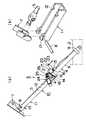
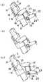
図1は本発明の一実施形態であるキャブ下降防止装置付きキャブチルト装置を示しており、(a)は側面図、(b)は主要部の拡大分解斜視図である。図2および図3はその作用を説明するための説明図である。
【0009】
本実施形態を図1(a)および図1(b)によって説明すると、本発明に係るキャブ下降防止装置付きキャブチルト装置は、キャブと車体(フレーム)との間に介設されてキャブのチルト操作を行うように構成されている。キャブ下降防止装置付きキャブチルト装置3はキャブ1とフレーム2との間に介設されたシリンダ装置4を備えており、シリンダ装置4はピストンロッド5の上端部がキャブ1に装備されたロストモーションリンクレバー装置7にピン8によって連結されており、シリンダ6の下端部がフレーム2にピン9によって回動自在に枢支されている。
【0010】
キャブ下降防止装置10はシリンダ装置4に付設されており、ピストンロッド5の上端部に一端部を枢着されたステー11を備えている。ステー11は剛性を有する金属材料からなり長い略H型鋼形状に形成されており、ステー11の中間部における両端辺には複数の歯12が鋸歯状に切設されている。歯12はそのキャブ側(以下、上側という。)が傾斜し、フレーム側(以下、下側という。)が端辺に対して略直角になるような略半台形形状に形成されている。
【0011】
ステー11のピストンロッド5への枢着端はキャブ1側に移動可能に構成されている。すなわち、ステー11の上端部には長孔13がステー11の長さ方向に長く開設されており、長孔13にはピストンロッド5およびロストモーションリンクレバー装置7に枢着されたピン8が回動かつ摺動自在に挿入されている。
【0012】
図2(a)において、シリンダ6の上端部にはチャンネル形状に形成されたスライドガイド14が、シリンダ6を跨ぐように配されて溶接等によって固定されており、スライドガイド14の内周とシリンダ6の外周との間にはステー11が摺動自在に挿入されている。シリンダ6の上端部におけるスライドガイド14の反対側にはブラケット15が配されて溶接等によって固定されており、ブラケット15には略ラチェット爪形状に形成されたロックレバー17の一端部がピン16によって回動自在に枢支されている。ロックレバー17の自由端部である上端部にはステー11の歯12に噛合自在な爪部18が形成されている。図1(a)において、ロックレバー17にはスプリング19の一端が係止されており、スプリング19の他端はスライドガイド14に係止されている。スプリング19はロックレバー17をその爪部18がステー11に接近する方向に常時付勢するようになっており、ロックレバー17の爪部18はロックレバー17がスプリング19で付勢されることにより、ステー11の歯12に噛合するようになっている。
【0013】
図2(a)において、ロックレバー17を枢支したピン16にはL字形状の解除レバー20がその中間部を回動自在に支承されており、解除レバー20の一方の自由端部である作用側端部21はロックレバー17にステー11の歯12との噛合を解除させる方向に係止されている。解除レバー20の他方の自由端部である力点側端部22にはケーブル23が係止されており、ケーブル23は人力またはアクチュエータ等の機械力により外力を付勢されて解除レバー20をスプリング19に抗して回動させるように構成されている。
【0014】
図1(a)において、スライドガイド14の一方の側面には停止スイッチ24が装備されており、停止スイッチ24の検出子25にはロックレバー17に突設されたプレート26が当接するようになっている。プレート26はロックレバー17がその爪部18がステー11の下端面11aと対向する位置まで回動しきった状態でのみ、停止スイッチ24の検出子25と当接するように設定されており、停止スイッチ24は検出子25にプレート26が当接したことをシリンダ装置4のコントローラ(図示せず)に送信するように設定されている。そして、コントローラは停止スイッチ24からの送信に基づいて、シリンダ装置4のピストンロッド5の伸長作動を停止するように設定されている。
【0015】
次に作用を説明する。
走行中等のキャブ1の通常状態において、キャブ下降防止装置付きキャブチルト装置3はシリンダ装置4のピストンロッド5が短縮されており、キャブ下降防止装置10におけるステー11はその略根元までスライドガイド14に挿入した状態になっている。
【0016】
エンジン部分の保守点検作業等に際して、キャブ1をキャブ下降防止装置付きキャブチルト装置3によってチルトされる場合には、シリンダ装置4のシリンダ6に油圧が供給されることにより、ピストンロッド5が伸長される。この際、ステー11の歯12の上面が上向きに傾斜されているため、ピストンロッド5の伸長に伴って上昇するステー11の歯12に対してロックレバー17は空滑りする状態になり、歯12と爪部18との噛合は発生しない。そして、ピストンロッド5と一緒にステー11が上昇してステー11の下端面11aにロックレバー17の爪部18が落ち込むと、プレート26が検出子25に当接することにより停止スイッチ24が発信するため、コントローラは停止スイッチ24からの送信に基づいて、シリンダ装置4のピストンロッド5の伸長作動を停止させる。この停止作用によって、ピストンロッド5の過度の伸長作動は自動的に防止される。
【0017】
エンジン部分の保守点検作業中等のキャブがチルトされている状態において、シリンダ装置4に故障等が発生し、キャブの荷重を受けてピストンロッド5が短縮しようとした場合、ステー11はこの短縮に追従して下降する状態になる。このとき、ステー11の歯列にスプリング19により常時押接されているロックレバー17における爪部18は、最寄りの歯12に直ちに噛合する。この噛合により、ステー11は歯12、ロックレバー17、ブラケット15を介してシリンダ6に支持された状態になる。これにより、ステー11が連結されているピストンロッド5は短縮を阻止されるため、キャブ1は下降を防止される。したがって、シリンダ装置4の故障時におけるキャブ1の下降による不慮の人身事故等を未然に防止することができる。
【0018】
保守点検作業後等にキャブを下降させたい場合には、ケーブル23によって解除レバー20をロックレバー17を持ち上げる方向に回動させることにより、ロックレバー17の爪部18と歯12との噛合を解除させればよい。ロックレバー17と歯12との噛合によるステー11についての拘束が解除された後に、キャブ1はシリンダ装置4のピストンロッド5の短縮に伴って下降される。
【0019】
ところで、従来においては、図3(a)に示されているように、シリンダ装置に図示しないチェック弁からの油洩れによる微少の収縮が発生し、ロックレバー17の爪部18がステー11の下端面11aに干渉している状態においては、ケーブル23を引いても解除レバー20を回動させることができない場合が発生していた。解除されない場合には、シリンダ装置4を一度伸長作動させることにより、図3(b)に示されているように、ステー11の下端面11aをロックレバー17の爪部18から一度離間させる。それから、図3(c)に示されているように、ケーブル23を引いて解除レバー20を回動させて、ロックレバー17の爪部18とステー11の下端面11aとの係合を解除させる。このようにして、ロックレバー17の爪部18のステー11の下端面11aとの係合を確実に解除させた後に、シリンダ装置4を短縮作動させてキャブ1を下降させていた。
【0020】
本実施形態においては、図1(a)に示されているように、ピストンロッド5のピン8がステー11の長孔13に長手方向に摺動自在に嵌入されていることにより、ステー11がピストンロッド5に対してキャブ1の方向に移動可能に取り付けられているため、たとえ、ロックレバー17の爪部18がステー11の下端面11aに干渉している状態においても、ケーブル23を引いて解除レバー20を回動させることができる。すなわち、ケーブル23が引かれることによって解除レバー20に回動力が作用すると、図2(a)に示されているように、その回動力はロックレバー17に対して爪部18でステー11の下端面11aを押し上げる力を付勢する。この押し上げ力を付勢されたステー11は図2(b)に示されているようにキャブ1の方向に移動することができるため、ステー11は解除レバー20の回動を妨げることなく、キャブ1の方向に移動することになる。解除レバー20が回動されると、図2(c)に示されているように、ロックレバー17が回動されるため、ステー11およびピストンロッド5はシリンダ6に対して短縮可能な状態になる。そして、シリンダ装置4が短縮作動されると、ステー11およびピストンロッド5はシリンダ6に対して短縮作動するため、キャブ1は下降し水平の状態に戻る。
【0021】
以上説明したように、本実施形態によれば、ピストンロッド5のピン8をステー11の長孔13に長手方向に摺動自在に嵌入させることにより、ステー11をピストンロッド5に対してキャブ1の方向に移動させることができるため、たとえ、ロックレバー17の爪部18がステー11の下端面11aに干渉している状態においても、ケーブル23を引いて解除レバー20を回動させてロックレバー17とステー11との係合を解除させることができる。したがって、煩わしい操作を必要とすることなく、ステー11およびピストンロッド5をシリンダ6に対して短縮させてキャブ1を下降させることができる。
【0022】
なお、本発明は前記実施形態に限定されるものではなく、その要旨を逸脱しない範囲において、種々変更可能であることはいうまでもない。
【0023】
例えば、ピストンロッド5のピン8をステー11の長孔13に長手方向に摺動自在に嵌入させることにより、ステー11をピストンロッド5に対してキャブ1の方向に移動可能に構成するに限らず、達磨孔や大径孔等によってステー11をピストンロッド5に対してキャブ1の方向に移動可能に構成してもよい。
【0024】
また、長孔等をピストンロッド5に設けるようにすることができる。すなわち、ピン8をステー11に固着してピストンロッド側に長孔を設けるようにする。この場合でも、前記実施形態と同様の作用効果が得られる。
【0025】
【発明の効果】
以上説明したように、本発明によれば、ロックレバーの爪部がステーの下端面に干渉している状態においても、解除レバーを回動させてロックレバーとステーとの係合を解除させることができるため、煩わしい操作を必要とすることなく、ステーおよびピストンロッドをシリンダに対して短縮させることができ、キャブを容易に下降させることができる。
【図面の簡単な説明】
【図1】本発明の一実施形態であるキャブ下降防止装置付きキャブチルト装置を示しており、(a)は側面図、(b)は主要部の拡大分解斜視図である。
【図2】その作用を説明するための各一部省略一部切断部分側面図であり、(a)は解除レバーによるロックレバーの解除作用を示し、(b)はステーのキャブ方向への移動を示し、(c)は解除後を示している。
【図3】同じく比較例の各一部省略一部切断部分側面図であり、(a)はロックレバーがステー下端面に干渉している状態を示し、(b)はステー下端面をロックレバーから一度離間させる状態を示し、(c)は解除作用を示している。
【符号の説明】
1…キャブ、2…フレーム、3…キャブ下降防止装置付きキャブチルト装置、4…シリンダ装置、5…ピストンロッド、6…シリンダ、7…ロストモーションリンクレバー装置、8…ピン、9…ピン、10…キャブ下降防止装置、11…ステー、11a…下端面、12…歯、13…長孔、14…スライドガイド、15…ブラケット、16…ピン、17…ロックレバー、18…爪部、19…スプリング、20…解除レバー、21…作用側端部、22…力点側端部、23…ケーブル、24…停止スイッチ、25…検出子、26…プレート。[0001]
BACKGROUND OF THE INVENTION
The present invention relates to a cab tilt device that lifts a cab with a cylinder device in a cab-over type automobile and tilts the cab. Relates to the device.
[0002]
[Prior art]
In general, a cab-over type automobile is configured such that maintenance and inspection of an engine portion can be easily performed by lifting and tilting the cab. In this case, since the cab is heavy, a cabylt device is used in which a cylinder device is interposed between the cab and the vehicle body (frame), and the cab is tilted by the expansion and contraction of the cylinder device. Sometimes.
[0003]
In this cabylt device, a cab lowering prevention device is attached in order to avoid the danger of the cab descending when a failure occurs in the cylinder device. A general cab lowering prevention device includes a stay pivoted on an upper end portion of a piston rod of a cylinder device, a plurality of teeth cut on the stay, and a lock lever pivoted on a cylinder of the cylinder device and meshed with the teeth. In the unlikely event that the piston rod starts to descend due to a failure in the hydraulic circuit, etc., the lock lever engages with the tooth closest to the stay to prevent the piston rod from descending. Yes.
[0004]
[Problems to be solved by the invention]
In a conventional cabbutylt device with a cab lowering prevention device, slight contraction due to oil leakage from a cylinder device, a check valve or the like occurs due to characteristics. At this time, when the release operation of the cab lowering prevention device is performed, the engagement portion between the stay end portion and the lock lever interferes with each other, and there is a case where the release is not released. If it is not released, it is necessary to carry out a troublesome procedure of operating the cylinder device once after extending the cylinder device and then performing a release operation and then lowering the cab by operating the cylinder device in a shortened manner.
[0005]
An object of the present invention is to provide a cabbutyl device with a cab lowering prevention device that can reliably release the restraint of the cab lowering prevention device.
[0006]
The cab tilt device with the cab lowering prevention device according to the present invention is configured such that the cab is tilted by a cylinder device interposed between the cab and the frame, and the tilted cab is prevented from descending. cab lowering prevention device which isa cab lowering prevention device with Kyabuchiruto device that is attached to the cylinder device,
The cab lowering prevention device includes a stay having one end pivotally attached to an upper end portion of a piston rod of the cylinder device pivotally attached to the cab, and a lock lever that engages with a lower end surface of the stay when the piston rod is extended. With
The stay is configured to be movable toward the cabwhen the lock lever is engaged with the lower end surface .
[0007]
According to the above means, since the pawl portion of the locking lever is in a state in which interfere with the lower end face of a stay, the release lever is rotated, the stay is to be moved in the direction of a cab by its rotating force,locking The claw part of the lever comes off from the lower end surface of the stay, andthe stay and the piston rod can be shortened with respect to the cylinder. When the cylinder device is shortened, the stay and the piston rod are shortened relative to the cylinder, so that the cab can be lowered and returned to the horizontal state.
[0008]
DETAILED DESCRIPTION OF THE INVENTION
1A and 1B show a cabylt device with a cab lowering prevention device according to an embodiment of the present invention, wherein FIG. 1A is a side view and FIG. 1B is an enlarged exploded perspective view of a main part. 2 and 3 are explanatory diagrams for explaining the operation.
[0009]
Referring to FIGS. 1A and 1B, this embodiment will be described. A cab tilt device with a cab lowering prevention device according to the present invention is interposed between a cab and a vehicle body (frame) and is operated to tilt the cab. Is configured to do. The cab tilt device 3 with the cab lowering prevention device includes a cylinder device 4 interposed between the cab 1 and the frame 2, and the cylinder device 4 has a lost motion link in which the upper end portion of the
[0010]
The cab
[0011]
The pivot end of the stay 11 to the
[0012]
In FIG. 2A, a
[0013]
In FIG. 2 (a), an L-shaped
[0014]
In FIG. 1A, a
[0015]
Next, the operation will be described.
In the normal state of the cab 1 such as during traveling, the cablutt device 3 with the cab lowering prevention device has the
[0016]
When the cab 1 is tilted by the cablutt device 3 with a cab lowering prevention device during maintenance and inspection of the engine portion, the
[0017]
In the state where the cab is tilted, such as during maintenance and inspection of the engine portion, when the cylinder device 4 fails, the stay 11 follows this shortening when the
[0018]
To lower the cab after maintenance work, etc., the
[0019]
In theprior art, as shown in FIG. 3A, the cylinder device is slightly contracted due to oil leakage from a check valve (not shown), and the
[0020]
In this embodiment, as shown in FIG. 1A, the
[0021]
As described above, according to this embodiment, the pin 11 of the
[0022]
Needless to say, the present invention is not limited to the above-described embodiment, and various modifications can be made without departing from the scope of the present invention.
[0023]
For example, the stay 11 can be moved in the direction of the cab 1 with respect to the
[0024]
Further, a long hole or the like can be provided in the
[0025]
【The invention's effect】
As described above, according to the present invention, even when the claw portion of the lock lever interferes with the lower end surface of the stay, the release lever is rotated to release the engagement between the lock lever and the stay. Therefore, the stay and the piston rod can be shortened with respect to the cylinder without requiring a troublesome operation, and the cab can be easily lowered.
[Brief description of the drawings]
BRIEF DESCRIPTION OF DRAWINGS FIG. 1 shows a cabylt device with a cab lowering prevention device according to an embodiment of the present invention, wherein (a) is a side view and (b) is an enlarged exploded perspective view of a main part.
FIGS. 2A and 2B are side views of each partially omitted part for explaining the operation, wherein FIG. 2A shows the release action of the lock lever by the release lever, and FIG. 2B shows the movement of the stay in the cab direction; (C) shows after release.
FIG. 3 is a partially cut-away side view of the comparative example, where FIG. 3 (a) shows a state where the lock lever interferes with the lower end surface of the stay, and FIG. (C) shows the releasing action.
[Explanation of symbols]
DESCRIPTION OF SYMBOLS 1 ... Cab, 2 ... Frame, 3 ... Cabbutylt device with cab lowering prevention device, 4 ... Cylinder device, 5 ... Piston rod, 6 ... Cylinder, 7 ... Lost motion link lever device, 8 ... Pin, 9 ... Pin, 10 ... Cab lowering prevention device, 11 ... stay, 11a ... lower end surface, 12 ... teeth, 13 ... long hole, 14 ... slide guide, 15 ... bracket, 16 ... pin, 17 ... lock lever, 18 ... claw, 19 ... spring, DESCRIPTION OF
Claims (1)
Translated fromJapanese前記キャブ下降防止装置は、前記キャブに枢着された前記シリンダ装置のピストンロッド上端部に一端部が枢着されたステーと、前記ピストンロッド伸長時に前記ステーの下端面に係合するロックレバーとを備えており、
前記ステーは、前記下端面に前記ロックレバーが係合した時に前記キャブ側に移動可能に構成されていることを特徴とするキャブ下降防止装置付きキャブチルト装置。The cab is tilted by a cylinder device interposed between the cab and the frame, and a cab lowering prevention device for preventing the tilted cab from descending is attached to the cylinder device.a cab down prevention device with Kyabuchiruto apparatus,
The cab lowering prevention device includes a stay having one end pivotally attached to an upper end portion of a piston rod of the cylinder device pivotally attached to the cab, and a lock lever that engages with a lower end surface of the stay when the piston rod is extended. With
The stay is configured to be movable to the cab sidewhen the lock lever is engaged with the lower end surface .
Priority Applications (1)
| Application Number | Priority Date | Filing Date | Title |
|---|---|---|---|
| JP24180497AJP4040148B2 (en) | 1997-08-22 | 1997-08-22 | Cabbutylt device with cab lowering prevention device |
Applications Claiming Priority (1)
| Application Number | Priority Date | Filing Date | Title |
|---|---|---|---|
| JP24180497AJP4040148B2 (en) | 1997-08-22 | 1997-08-22 | Cabbutylt device with cab lowering prevention device |
Publications (3)
| Publication Number | Publication Date |
|---|---|
| JPH1159506A JPH1159506A (en) | 1999-03-02 |
| JPH1159506A5 JPH1159506A5 (en) | 2005-05-19 |
| JP4040148B2true JP4040148B2 (en) | 2008-01-30 |
Family
ID=17079763
Family Applications (1)
| Application Number | Title | Priority Date | Filing Date |
|---|---|---|---|
| JP24180497AExpired - Fee RelatedJP4040148B2 (en) | 1997-08-22 | 1997-08-22 | Cabbutylt device with cab lowering prevention device |
Country Status (1)
| Country | Link |
|---|---|
| JP (1) | JP4040148B2 (en) |
Cited By (1)
| Publication number | Priority date | Publication date | Assignee | Title |
|---|---|---|---|---|
| CN108216390A (en)* | 2017-12-04 | 2018-06-29 | 北汽福田汽车股份有限公司 | Driver's cabin strut and vehicle |
Families Citing this family (15)
| Publication number | Priority date | Publication date | Assignee | Title |
|---|---|---|---|---|
| JP3808288B2 (en)* | 2000-07-19 | 2006-08-09 | 本田技研工業株式会社 | Vehicle hood device |
| US6554086B1 (en) | 2000-10-27 | 2003-04-29 | Invacare Corporation | Obstacle traversing wheelchair |
| US7040429B2 (en) | 2001-10-10 | 2006-05-09 | Invacare Corporation | Wheelchair suspension |
| PT2364868E (en)* | 2002-08-16 | 2013-01-31 | Invacare Corp | Vehicle having an anti-dive/lockout mechanism |
| US6851711B2 (en)* | 2002-08-16 | 2005-02-08 | Invacare Corporation | Vehicle having an anti-dive/lockout mechanism |
| US11213441B2 (en) | 2002-10-25 | 2022-01-04 | Invacare Corporation | Suspension for wheeled vehicles |
| US7293801B2 (en) | 2003-08-18 | 2007-11-13 | Invacare Corporation | Self-stabilizing suspension for wheeled vehicles |
| EP2111203B1 (en) | 2007-02-08 | 2011-01-05 | Invacare Corporation | Wheelchair suspension |
| CA2911675C (en) | 2007-02-14 | 2018-09-18 | Invacare Corporation | Stability control system |
| EP2485698B1 (en) | 2009-10-09 | 2017-05-17 | Invacare Corporation | Wheelchair suspension |
| AU2013221283B2 (en) | 2012-02-15 | 2017-05-25 | Invacare Corporation | Wheelchair suspension |
| CN102627126A (en)* | 2012-04-23 | 2012-08-08 | 上汽依维柯红岩商用车有限公司 | Cab lifting-overturning failure protection device |
| JP6790801B2 (en)* | 2016-12-20 | 2020-11-25 | いすゞ自動車株式会社 | Cabilt stay lock device |
| CN106965862B (en)* | 2017-04-28 | 2023-03-17 | 徐州徐工汽车制造有限公司 | Failure protection mechanism for cab lifting and overturning system |
| AU2021228590A1 (en) | 2020-02-25 | 2022-09-22 | Invacare Corporation | Wheelchair and suspension systems |
- 1997
- 1997-08-22JPJP24180497Apatent/JP4040148B2/ennot_activeExpired - Fee Related
Cited By (2)
| Publication number | Priority date | Publication date | Assignee | Title |
|---|---|---|---|---|
| CN108216390A (en)* | 2017-12-04 | 2018-06-29 | 北汽福田汽车股份有限公司 | Driver's cabin strut and vehicle |
| CN108216390B (en)* | 2017-12-04 | 2019-10-22 | 北汽福田汽车股份有限公司 | Driver's cabin strut and vehicle |
Also Published As
| Publication number | Publication date |
|---|---|
| JPH1159506A (en) | 1999-03-02 |
Similar Documents
| Publication | Publication Date | Title |
|---|---|---|
| JP4040148B2 (en) | Cabbutylt device with cab lowering prevention device | |
| CN109382805B (en) | Work support device capable of freely lifting | |
| EP0317117A2 (en) | Hand brake assembly for a vehicle | |
| JPS6327264B2 (en) | ||
| US5803206A (en) | Hoist locking and release apparatus | |
| JPH1088620A (en) | Pedal locking device for loader | |
| US3982636A (en) | Car lifting apparatus | |
| EP0520401A1 (en) | Toggle type parking brake lever apparatus | |
| JP5091498B2 (en) | Tilt cabin stopper structure | |
| GB2034408A (en) | Safety device for hydraulic lifting apparatus | |
| JP2888418B2 (en) | Lighting equipment lifting device | |
| JP3917443B2 (en) | Vehicle maintenance lift | |
| JP4346160B2 (en) | Cab descent prevention device | |
| JP4021884B2 (en) | Emergency stop mechanism of lift device | |
| JP2000006853A (en) | Cab tilt device | |
| JP3120996U (en) | Vehicle-mounted crane | |
| JPS635995Y2 (en) | ||
| JP2513695Y2 (en) | Cab down prevention device | |
| JP7681536B2 (en) | Fall prevention device and lifting cart | |
| JP2556827Y2 (en) | Driver's cab lifting device | |
| JPS6124454Y2 (en) | ||
| JPS6330621Y2 (en) | ||
| JP4671495B2 (en) | Cabylt equipment | |
| JPS6333744Y2 (en) | ||
| JP2582844Y2 (en) | Cab elevator for construction machinery |
Legal Events
| Date | Code | Title | Description |
|---|---|---|---|
| A521 | Written amendment | Free format text:JAPANESE INTERMEDIATE CODE: A523 Effective date:20040707 | |
| A621 | Written request for application examination | Free format text:JAPANESE INTERMEDIATE CODE: A621 Effective date:20040707 | |
| A131 | Notification of reasons for refusal | Free format text:JAPANESE INTERMEDIATE CODE: A131 Effective date:20070807 | |
| A521 | Written amendment | Free format text:JAPANESE INTERMEDIATE CODE: A523 Effective date:20071005 | |
| TRDD | Decision of grant or rejection written | ||
| A01 | Written decision to grant a patent or to grant a registration (utility model) | Free format text:JAPANESE INTERMEDIATE CODE: A01 Effective date:20071106 | |
| A61 | First payment of annual fees (during grant procedure) | Free format text:JAPANESE INTERMEDIATE CODE: A61 Effective date:20071107 | |
| FPAY | Renewal fee payment (event date is renewal date of database) | Free format text:PAYMENT UNTIL: 20101116 Year of fee payment:3 | |
| R150 | Certificate of patent or registration of utility model | Free format text:JAPANESE INTERMEDIATE CODE: R150 | |
| FPAY | Renewal fee payment (event date is renewal date of database) | Free format text:PAYMENT UNTIL: 20101116 Year of fee payment:3 | |
| FPAY | Renewal fee payment (event date is renewal date of database) | Free format text:PAYMENT UNTIL: 20111116 Year of fee payment:4 | |
| FPAY | Renewal fee payment (event date is renewal date of database) | Free format text:PAYMENT UNTIL: 20121116 Year of fee payment:5 | |
| FPAY | Renewal fee payment (event date is renewal date of database) | Free format text:PAYMENT UNTIL: 20131116 Year of fee payment:6 | |
| R250 | Receipt of annual fees | Free format text:JAPANESE INTERMEDIATE CODE: R250 | |
| S531 | Written request for registration of change of domicile | Free format text:JAPANESE INTERMEDIATE CODE: R313531 | |
| R350 | Written notification of registration of transfer | Free format text:JAPANESE INTERMEDIATE CODE: R350 | |
| R250 | Receipt of annual fees | Free format text:JAPANESE INTERMEDIATE CODE: R250 | |
| R250 | Receipt of annual fees | Free format text:JAPANESE INTERMEDIATE CODE: R250 | |
| LAPS | Cancellation because of no payment of annual fees |