JP4038254B2 - Coin game machine coin tray - Google Patents
Coin game machine coin trayDownload PDFInfo
- Publication number
- JP4038254B2 JP4038254B2JP12790697AJP12790697AJP4038254B2JP 4038254 B2JP4038254 B2JP 4038254B2JP 12790697 AJP12790697 AJP 12790697AJP 12790697 AJP12790697 AJP 12790697AJP 4038254 B2JP4038254 B2JP 4038254B2
- Authority
- JP
- Japan
- Prior art keywords
- coin
- opening
- bottom plate
- movable bottom
- locking
- Prior art date
- Legal status (The legal status is an assumption and is not a legal conclusion. Google has not performed a legal analysis and makes no representation as to the accuracy of the status listed.)
- Expired - Fee Related
Links
Images


Landscapes
- Slot Machines And Peripheral Devices (AREA)
Description
Translated fromJapanese【0001】
【発明の属する技術分野】
本発明は、スロットマシンなどのようにコインが払い出されるコインゲーム機のコイン皿の改良に関するものである。
【0002】
【従来の技術】
従来、この種のコインゲーム機のコイン皿はゲーム機本体の下部前面に設けられて、コイン払出装置から払い出されたコインを受け入れるようになっている。そしてコインが溜ったときやゲームを終えるときはコイン皿のコインを何回も指で掻き寄せて、コイン皿の前側壁を乗り越えさせてコイン貯留容器に移し替えている。このために、コイン皿はコインを取り出し易くするように周壁を低く、つまり浅く作られていてコインを収容できる容量が限られていた。
【0003】
【発明が解決しようとする課題】
しかしながら、ゲームでいわゆる「大当たり」が発生して大量のコインが払い出されると忽ちコイン皿からコインが溢れ、ゲームを中断してコインを取り出さねばならないために著しくゲームの興趣を損なうことになる。また、貯ったコインをコイン貯留容器に移し替えるためにコイン皿から何回も掻き出さねばならず、その手間が大変面倒でしかも最近増えた女性客の爪が割れたり傷ついたりするという問題があった。
そこで本発明は、コイン皿からコインを一々手で掻き出してコイン貯留容器に移し替えることなく一気にコイン貯留容器に移し替えることができるコイン皿を提供することを目的としている。
【0004】
【課題を解決するための手段】
本発明は上記目的を達成するために提案されたもので、ゲーム機本体の前面下方にコイン払出装置から払出されたコインを受け入れるコイン皿を有するコインゲーム機において、前記コイン皿の底壁に開口部を設け、該開口部の左右開口端に突出壁を垂設し、該突出壁に係合孔を設けると共に、該開口部を開閉する可動底板を設け、該可動底板の後端側を前記開口部の後端で枢支させ、枠部材を該可動底板の下面に取着し、該枠部材の前端に支持段部を設け、先端に前記係合孔に係合する係止片部が形成された一対の係止部材を枠部材内に左右に往復動可能に設け、一対の作動部材を該枠部材内に前後に往復動可能に設け、該作動部材をコイルばねにより前方に弾発付勢させて該作動部材の先端を前記支持段部の上部に突出させ、該作動部材と前記係止部材とを直交状に連繋させてなり、コイン貯留容器の先端上縁を作動部材の先端に当接させてコイルばねの付勢に抗して該コイン貯留容器を押し付け該作動部材を後退動させることで前記係止部材が互いに内側へ摺動し、係止片部が係合孔から離脱することで可動底板を下傾させて開口部を開放させ、該コイン貯留容器が支持段部に支持された状態でコイン皿に溜っているコインが該コイン貯留容器内に落下するようにしたことを特徴とする。
【0008】
【発明の実施の形態】
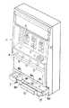
以下に本発明に係わるコインゲーム機のコイン皿の実施の形態を図面と共に説明する。図1は本発明が適用されるスロットマシンの斜視図、図2は断面図でありる。ゲーム機本体1の前面には上部に3個のリール2,2,2が横並びに配列され、その下方にコイン投入口3とスタートレバー4及び3個のストップボタン5,5,5が配置される。そして、ゲーム機本体1の下部中央にコイン払出装置6から払出されたコインの払出口6aが設けられ、このコイン払出口6aの下方にコイン皿7が設けられる。
【0009】
このスロットマシンは、コイン投入口3にコインを投入した後、スタートレバー4を操作して3個のリール2,2,2を回転させ、次いでストップボタン5,5,5を順次押してそれらに対応する前記リール2,2,2を停止させ、その際のリール2,2,2の各外周面に表示した図柄の組み合わせが一定の有効図柄の組み合わせになると所定枚数のコインをコイン払出装置6から払い出し、コイン皿7に受けるようになっている。
【0010】
しかして、前記コイン皿7は合成樹脂製で、四方側壁8a〜8dと底壁9とで上面で開口した箱状に形成される。そして、前記底壁9に開口部10を設けその左右両側を開口部10に向かって傾斜する傾斜底壁9a,9aとしている。
11は前記開口部10を開閉する可動底板であり、該可動底板11には後側端の左右に支軸12,12を突設してこれらの支軸12,12を開口部10の後側端両側に設けた係合凹部13,13に枢支させる。
【0011】
前記可動底板11の前側端にコイン皿7の前側壁8a前面に沿わせる立壁14を立設し、該立壁14の上端に前方へ水平に突出する支持枠15を延設し、該支持枠15の水平片部15aの下面に一対の軸部16,16を突設している。そして前記立壁14の下部には複数のリブ14aで区画された開口窓17を設ける。そして、これらのリブに14a対向位置させて前記可動底板11の上面前部寄りに、断面三角形でしかも前端に向けて次第に高くなる突畝18,18を突設し、コインの移し替えに際してコインを突畝18,18で振り分けさせ、リブ14aに当たることなく開口窓17から落下させるようにしている。
【0012】
19は可動底板11が開口部10を閉塞した状態を保持させる係止部材で、水平片部19aと垂直片部19bとで断面逆L字形状の板材で形成される。そして水平片部19aに前記軸部16,16を遊嵌させる長孔20,20を開設し、該水平片部19aをコイン皿7の前側壁8aに水平に設けた係合溝21に係合させる係止部19cとしている。
【0013】
22は前記係止部材19をガイドするガイド部材である。該ガイド部材22は断面凵形をしており、一端に前記立壁14と面一で開口窓17の一部を塞ぐ垂下壁を設けている。そして、係止部材22を嵌めて前記支持枠15の軸部16,16に対してガイド部材22の下面からそれぞれビス23,23を螺締して固定させる。
【0014】
また係止部材19の垂直片部19bの前側面に短軸24を突設して該短軸24にコイルばね25の一端側を遊嵌させる。該コイルばね25の他端は支持枠15の垂直片部15bの内側面に設けた凹穴26に遊嵌させ、該コイルばね25の弾発付勢で係止部材19の係止部19cをコイン皿7の前側壁8aに設けた係合溝21に係合させ、図5実線で示すように可動底板11で開口部10を閉塞させる。
【0015】
前記開口部10の左右開口端に図3及び図5に示すように突出壁27をそれぞれ垂設し、これらの突出壁27,27の内側面に可動底板11を下傾させた状態を保持させる突条28,28を傾斜させて対設している。さらにコイン皿7の後側壁8cの下端に図6に示すように逆L字形の支持片29を突設している。該支持片29はコイン貯留容器Aの上端縁の鍔部を支持するためのものである。
【0016】
このように構成されるコイン皿7に溜ったコインCを取り出すには、図6に示すようにコイン皿7の下方にコイン貯留容器Aを配しその先端側の上端縁を支持片29に支持させた状態で片手でコイン貯留容器Aを支え、他方の手の指先Fで図4に示すように係止部材19の垂直片部19bをコイルばね25の付勢に抗して前方へ引き寄せることにより、係止部材19を実線位置から鎖線位置へ移動させて係止片19cと係合溝21との係合を解除し、可動底板11が下傾して開口部10を開放すると共に、突条28,28で支持されてコイン皿7に溜っているコインCが可動底板11上をすべりながら立壁14の下部に設けた開口窓16から転落し、コイン皿7のコインCを一気にコイン貯留容器Aに移し替えることができる。
このように、コインを移し替えた後可動底板11を元に戻すには支持枠15を上動させると係止部材19の係止部19cがコイルばね25の付勢に抗して前側壁8aで押されて後退し係合溝21と合致する位置にくるとコイルばね25の付勢により係止部19cと係合溝21が係合して可動底板11が開口部10を閉塞する。
【0017】
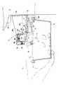
次に可動底板11の開放をコイン貯留容器Aで行なう実施の形態を示す。この実施の形態で前記実施の形態に示したものと同じ構成の個所は同一の符号を付して重複する説明は省略する。30は可動底板11の下面にビス31を介して取着させる枠部材であり、該枠部材30の上面に囲い壁32を立設している。そして枠部材30の前端にコイン貯留容器Aの上端縁を支持する支持段部30aを設け、前記囲い壁32内で左右両側寄りに長方形をなす枠部33,33を一線上に対設して、これらの枠部33,33内に係止部材34,34を載置させる。これらの係止部材34,34には上面にピン35,35を立設し、先端に係止片部34a,34aを形成している。
【0018】
36,36は係止部材34,34上に直交させて係合させる作動部材であり、中央部に係止部材34,34の上面に立設したピン35,35を遊嵌させる長孔37,37を長手方向に対して斜め向きに開設し、先端36a,36aをテーパ面とし、作動部材36,36の後端36b,36bは枠部材30の上面に設けた区画部39,39内に臨ませ、該区画部39,39に装填されるコイルばね40,40で前方に弾発付勢させ前記囲い壁32の前壁32aに設けた切り欠き38,38から先方へ突出させる。そしてこれにともない長孔37,37に遊嵌されたピン35,35により係止部材34,34の係止片部34a,34aも枠部材30の外方へ突出する。
【0019】
前記可動底板11の下面には前記係止部材34,34及び作動部材36,36を往復動可能にガイドさせるガイド壁41,42がそれぞれ2条ずつ平行させて垂設される。また、前記突出壁27,27に係止部材34,34の係止片部34a.34aを係止させる係合孔43,43を設けている。
【0020】
この実施の形態では枠部材30上で区画部39,39内に装填したコイルばね40,40の弾発付勢で係止部材34,34及び作動部材36,36がそれぞれ図9実線位置にあって、係止部材34,34先端の係止片部34a,34aを突出壁27,27の係合孔43,43に係止させて可動底板11で開口部10を閉塞させている。
【0021】
このように開口部10を閉塞している可動底板11を開放させるには図11に示すようにコイン貯留容器Aの先端上縁を作動部材36,36の前端36a,36aに当接し、コイルばね40,40の付勢に抗してコイン貯留容器Aを押し付けて支持段部30aに支持させると長孔37,37に遊嵌させているピン35,35が図10に示すように互いに内側へ引き寄せられることで係止部材34,34を互いに内側へ摺動させ、係止片部34a,34aを係合孔43,43から離脱させ、図12に示すように可動底板11を下傾させて開口部10を開放させ、コイン皿7に溜っているコインを前側壁8a下端と可動底板11との開口44から転落させてコイン貯留容器Aに一気に収容することができる。この際コイン貯留容器Aの鍔部が支持段部30aに支持されているのでコインが一気にコイン貯留容器A内に落下しても、コインをこぼすことなく楽にコイン貯留容器Aを持つことができる。
【0022】
また可動底板11の上面を図13に示すように凸部45aと凹部45bとを交互に設けた凹凸面45に形成することで可動底板11の上面に接するコインCの少なくとも一部が確実に浮き上がって指先Fが掛かり易く、コインCが容易に掻き寄せることができる。
【0023】
【発明の効果】
以上に述べたように本発明に係わるコインゲーム機のコイン皿は底壁に設けた開口部を開閉させる可動底板の後端側を枢支させると共に、可動底板の前端側を係止部材により係止して常に可動底板により開口部を閉塞させ、前記係止部材の係止を解除することで可動底板を下傾させて開口部を開放させるものであるから、コイン皿に溜ったコインを容易にしかも手を汚すことなく迅速にコイン貯留容器に移し替えることができる。さらに、このようにコインを底壁に設けた開口部から取り出すものであるから側壁を高く形成してもコインの取り出しに全く支障はなく、側壁を高くできることでコイン皿のコイン収容量を増加させることができ、コインの移し替えを頻繁に行なわなくてもよくなり、コインの移し替えの都度ゲームを中断して興趣を殺ぐことも解消することができる。
【0024】
また、開閉部材の上面を凹凸面に形成することでコインが指先に掛かり易くなり、例えばゲーム中に残り少なくなったコインを取り出す際にも容易に掻き寄せて取り出すことができる。
【図面の簡単な説明】
【図1】 本発明が適用されるコインゲーム機の斜視図。
【図2】 図1の断面図。
【図3】 コイン皿の分解斜視図。
【図4】 コイン皿の平面断面図。
【図5】 開閉底を開放させる作用を説明するための縦断側面図。
【図6】 コインを移し替える状態の作用説明断面図。
【図7】 他の実施の形態を示すコイン皿の斜視図。
【図8】 他の実施の形態を示す分解斜視図。
【図9】 開閉底を開放させる作用を説明するための正面断面図。
【図10】 同平面断面図。
【図11】 開閉底を開放させる動作を示す縦断面側面図。
【図12】 開閉底を開放させた状態の縦断面側面図。
【図13】 可動底板上面を凹凸面にした正面断面図。
【符号の説明】
1 ゲーム機本体
6 コイン払出装置
7 コイン皿
9 底壁
10 開口部
11 可動底板
12,12 支軸
13,13 係合凹部
27,27 突出壁
30 枠部材
30a 支持段部
34,34 係止部材
34a,34a 係止片部
35,35 ピン
36,36 作動部材
36a,36a 作動部材の先端
37,37 長孔
38,38 切り欠き
40,40 コイルばね
43,43 係合孔
45 凹凸面
A コイン貯留容器[0001]
BACKGROUND OF THE INVENTION
The present invention relates to an improvement in a coin tray of a coin game machine in which coins are paid out, such as a slot machine.
[0002]
[Prior art]
Conventionally, a coin tray of this type of coin game machine is provided on the lower front surface of the game machine body so as to accept coins paid out from a coin payout device. When coins are accumulated or when the game is over, the coins on the coin tray are scraped many times with fingers, over the front side wall of the coin tray and transferred to the coin storage container. For this reason, the coin tray is made so that the peripheral wall is low, that is, shallow so as to make it easy to take out the coin, and the capacity for storing the coin is limited.
[0003]
[Problems to be solved by the invention]
However, when a so-called “big hit” occurs in the game and a large amount of coins are paid out, the coins overflow from the coin tray, and the game must be interrupted to take out the coins, which greatly impairs the interest of the game. Also, in order to transfer the accumulated coins to the coin storage container, it has to be scraped many times from the coin tray, which is very troublesome and the recently increased number of female customers' nails are cracked or damaged there were.
Therefore, an object of the present invention is to provide a coin tray that can be transferred to a coin storage container at once without scraping coins from the coin tray by hand and transferring them to the coin storage container.
[0004]
[Means for Solving the Problems]
The present invention has beenproposed in order to achieve the aboveobject, in a coin gaming machine having a coin tray for receiving the coins paid out to the front downward from the coin payout device of the game machine body, the bottom wall of the coin tray An opening is provided, a protruding wall is vertically suspended at the left and right opening ends of the opening, an engagement hole is provided in the protruding wall, a movable bottom plate that opens and closes the opening is provided, and a rear end side of the movable bottom plate is A locking piece that is pivotally supported at the rear end of the opening, the frame member is attached to the lower surface of the movable bottom plate, a support step is provided at the front end of the frame member, and the front end of the frame member is engaged with the engagement hole. A pair of locking members formed with, are provided in the frame member so as to be able to reciprocate left and right, and a pair of operating members are provided in the frame member so as to be able to reciprocate back and forth, and the operating members are elastically moved forward by a coil spring The operating member is urged to project the tip of the operating member above the support step, and the operating member The locking member is connected in an orthogonal shape, and the upper end edge of the coin storage container is brought into contact with the front end of the operation member to press the coin storage container against the bias of the coil spring. By moving backward, the locking members slide inward from each other, and when the locking piece part is detached from the engagement hole, the movable bottom plate is tilted downward to open the opening, and the coin storage container is The coins stored in the coin tray in a state of being supported by the unit fall into the coin storage container .
[0008]
DETAILED DESCRIPTION OF THE INVENTION
Embodiments of a coin tray of a coin game machine according to the present invention will be described below with reference to the drawings. FIG. 1 is a perspective view of a slot machine to which the present invention is applied, and FIG. 2 is a sectional view. Three
[0009]
In this slot machine, after inserting a coin into the
[0010]
The
Reference numeral 11 denotes a movable bottom plate that opens and closes the
[0011]
A standing wall 14 is erected on the front side end of the movable bottom plate 11 along the front surface of the
[0012]
[0013]
[0014]
A
[0015]
As shown in FIG. 3 and FIG. 5, projecting
[0016]
In order to take out the coins C accumulated in the
As described above, after the coin is transferred, the movable bottom plate 11 is returned to the original position. When the
[0017]
Next, an embodiment in which the movable bottom plate 11 is opened by the coin storage container A will be described. In this embodiment, parts having the same configurations as those shown in the above embodiment are given the same reference numerals, and redundant description is omitted. A
[0018]
[0019]
On the lower surface of the movable bottom plate 11, two
[0020]
In this embodiment, the locking
[0021]
In order to open the movable bottom plate 11 closing the
[0022]
Further, as shown in FIG. 13, the upper surface of the movable bottom plate 11 is formed on the concave /
[0023]
【The invention's effect】
As described above, the coin tray of the coin game machine according to the present invention pivotally supports the rear end side of the movable bottom plate that opens and closes the opening provided in the bottom wall, and the front end side of the movable bottom plate is engaged by the locking member. Since the opening is closed by always closing the opening with the movable bottom plate, and the opening of the movable bottom plate is released by releasing the locking of the locking member, the coins accumulated in the coin tray can be easily Moreover, it can be quickly transferred to the coin storage container without dirtying hands. Further, since the coin is taken out from the opening provided in the bottom wall in this way, even if the side wall is formed high, there is no hindrance to taking out the coin, and the side wall can be raised to increase the coin capacity of the coin tray. The coins do not need to be transferred frequently, and the game can be interrupted each time the coins are transferred to eliminate the interest.
[0024]
Further, by forming the upper surface of the opening / closing member on the uneven surface, the coins can be easily applied to the fingertips, and can be easily scraped and taken out, for example, when taking out the remaining coins during the game.
[Brief description of the drawings]
FIG. 1 is a perspective view of a coin game machine to which the present invention is applied.
FIG. 2 is a cross-sectional view of FIG.
FIG. 3 is an exploded perspective view of a coin tray.
FIG. 4 is a plan sectional view of a coin tray.
FIG. 5 is a vertical side view for explaining the action of opening the open / close bottom.
FIG. 6 is a sectional view for explaining an operation in a state where coins are transferred.
FIG. 7 is a perspective view of a coin tray showing another embodiment.
FIG. 8 is an exploded perspective view showing another embodiment.
FIG. 9 is a front sectional view for explaining the action of opening the open / close bottom.
FIG. 10 is a cross-sectional view of the same plane.
FIG. 11 is a longitudinal sectional side view showing an operation of opening the open / close bottom.
FIG. 12 is a longitudinal sectional side view of the state where the open / close bottom is opened.
FIG. 13 is a front sectional view in which the upper surface of the movable bottom plate is an uneven surface.
[Explanation of symbols]
DESCRIPTION OF SYMBOLS 1 Game machine body 6
27, 27 protruding wall
30 Frame member
30a Supporting step
34, 34 Locking member
34a, 34a Locking piece
35, 35 pins
36, 36 Actuating members
36a, 36a Actuating member tip
37, 37 long hole
38, 38 cutout
40, 40 coil spring
43, 43
A Coin storage container
Claims (1)
Translated fromJapanesePriority Applications (1)
| Application Number | Priority Date | Filing Date | Title |
|---|---|---|---|
| JP12790697AJP4038254B2 (en) | 1997-04-30 | 1997-04-30 | Coin game machine coin tray |
Applications Claiming Priority (1)
| Application Number | Priority Date | Filing Date | Title |
|---|---|---|---|
| JP12790697AJP4038254B2 (en) | 1997-04-30 | 1997-04-30 | Coin game machine coin tray |
Publications (2)
| Publication Number | Publication Date |
|---|---|
| JPH10295875A JPH10295875A (en) | 1998-11-10 |
| JP4038254B2true JP4038254B2 (en) | 2008-01-23 |
Family
ID=14971592
Family Applications (1)
| Application Number | Title | Priority Date | Filing Date |
|---|---|---|---|
| JP12790697AExpired - Fee RelatedJP4038254B2 (en) | 1997-04-30 | 1997-04-30 | Coin game machine coin tray |
Country Status (1)
| Country | Link |
|---|---|
| JP (1) | JP4038254B2 (en) |
Families Citing this family (3)
| Publication number | Priority date | Publication date | Assignee | Title |
|---|---|---|---|---|
| JP4654397B2 (en)* | 2003-12-05 | 2011-03-16 | 株式会社大一商会 | Game machine |
| JP4570024B2 (en)* | 2004-01-27 | 2010-10-27 | サミー株式会社 | Game machine |
| JP2007319242A (en)* | 2006-05-30 | 2007-12-13 | Aruze Corp | Game machine |
- 1997
- 1997-04-30JPJP12790697Apatent/JP4038254B2/ennot_activeExpired - Fee Related
Also Published As
| Publication number | Publication date |
|---|---|
| JPH10295875A (en) | 1998-11-10 |
Similar Documents
| Publication | Publication Date | Title |
|---|---|---|
| US4838454A (en) | Napkin dispenser | |
| US7516831B2 (en) | Coin-operated item vending and game apparatus housing with foreign object removal-enabling means | |
| US6467616B2 (en) | Apparatus for holding a disc-like article | |
| JP4038254B2 (en) | Coin game machine coin tray | |
| JP4106105B2 (en) | Coin game machine coin tray | |
| JPH0652885U (en) | Ball saucer for pachinko machines | |
| US2948379A (en) | Key and coin combination lock | |
| JP3965224B2 (en) | Coin game machine coin tray | |
| JP2000262709A (en) | Ball receiving tray of pachinko machine | |
| JP5467236B2 (en) | Game machine | |
| US3666068A (en) | Coin released mechanism in a vending machine | |
| JP3688565B2 (en) | Ball tray removal device for ball tray in pachinko machine | |
| JP3502418B2 (en) | Ball punching device for ball tray in pachinko machine | |
| JPS6230130Y2 (en) | ||
| JP3741806B2 (en) | Coin removal device for pachislot machines | |
| JP4143612B2 (en) | Coin removal device for pachislot machines | |
| US2896821A (en) | Glass slide dispenser | |
| JP3237062B2 (en) | Gaming machine | |
| JP3759985B2 (en) | vending machine | |
| JP3558671B2 (en) | Ball punching device for lower ball tray in pachinko machine | |
| JP3607173B2 (en) | Ball draining device for ball tray in pachinko machine | |
| JP2003154053A (en) | Token receptacle for pachinko-slot machine | |
| JP4004588B2 (en) | Medal payout mechanism | |
| JPH061751Y2 (en) | Lending device for game media | |
| JP2640833B2 (en) | Prize ball saucer in pachinko machine |
Legal Events
| Date | Code | Title | Description |
|---|---|---|---|
| A621 | Written request for application examination | Free format text:JAPANESE INTERMEDIATE CODE: A621 Effective date:20040408 | |
| A131 | Notification of reasons for refusal | Free format text:JAPANESE INTERMEDIATE CODE: A131 Effective date:20070522 | |
| A521 | Written amendment | Free format text:JAPANESE INTERMEDIATE CODE: A523 Effective date:20070718 | |
| TRDD | Decision of grant or rejection written | ||
| A01 | Written decision to grant a patent or to grant a registration (utility model) | Free format text:JAPANESE INTERMEDIATE CODE: A01 Effective date:20071016 | |
| A61 | First payment of annual fees (during grant procedure) | Free format text:JAPANESE INTERMEDIATE CODE: A61 Effective date:20071105 | |
| R150 | Certificate of patent or registration of utility model | Free format text:JAPANESE INTERMEDIATE CODE: R150 | |
| FPAY | Renewal fee payment (event date is renewal date of database) | Free format text:PAYMENT UNTIL: 20101109 Year of fee payment:3 | |
| FPAY | Renewal fee payment (event date is renewal date of database) | Free format text:PAYMENT UNTIL: 20131109 Year of fee payment:6 | |
| LAPS | Cancellation because of no payment of annual fees |