JP4035803B2 - Mobile packet communication system - Google Patents
Mobile packet communication systemDownload PDFInfo
- Publication number
- JP4035803B2 JP4035803B2JP04178499AJP4178499AJP4035803B2JP 4035803 B2JP4035803 B2JP 4035803B2JP 04178499 AJP04178499 AJP 04178499AJP 4178499 AJP4178499 AJP 4178499AJP 4035803 B2JP4035803 B2JP 4035803B2
- Authority
- JP
- Japan
- Prior art keywords
- node
- packet
- address
- location registration
- registration server
- Prior art date
- Legal status (The legal status is an assumption and is not a legal conclusion. Google has not performed a legal analysis and makes no representation as to the accuracy of the status listed.)
- Expired - Fee Related
Links
Images


Classifications
- H—ELECTRICITY
- H04—ELECTRIC COMMUNICATION TECHNIQUE
- H04W—WIRELESS COMMUNICATION NETWORKS
- H04W92/00—Interfaces specially adapted for wireless communication networks
- H04W92/02—Inter-networking arrangements
- H—ELECTRICITY
- H04—ELECTRIC COMMUNICATION TECHNIQUE
- H04W—WIRELESS COMMUNICATION NETWORKS
- H04W76/00—Connection management
- H04W76/20—Manipulation of established connections
- H—ELECTRICITY
- H04—ELECTRIC COMMUNICATION TECHNIQUE
- H04W—WIRELESS COMMUNICATION NETWORKS
- H04W88/00—Devices specially adapted for wireless communication networks, e.g. terminals, base stations or access point devices
- H04W88/14—Backbone network devices
- H—ELECTRICITY
- H04—ELECTRIC COMMUNICATION TECHNIQUE
- H04W—WIRELESS COMMUNICATION NETWORKS
- H04W92/00—Interfaces specially adapted for wireless communication networks
- H04W92/04—Interfaces between hierarchically different network devices
- H—ELECTRICITY
- H04—ELECTRIC COMMUNICATION TECHNIQUE
- H04W—WIRELESS COMMUNICATION NETWORKS
- H04W92/00—Interfaces specially adapted for wireless communication networks
- H04W92/16—Interfaces between hierarchically similar devices
- H04W92/24—Interfaces between hierarchically similar devices between backbone network devices
Landscapes
- Engineering & Computer Science (AREA)
- Computer Networks & Wireless Communication (AREA)
- Signal Processing (AREA)
- Data Exchanges In Wide-Area Networks (AREA)
- Mobile Radio Communication Systems (AREA)
- Small-Scale Networks (AREA)
Description
Translated fromJapanese【0001】
【発明の属する技術分野】
本発明は、セルラー通信網等の高速移動通信システムにおけるインターネット通信等のデータ通信をサポートする移動パケット通信システムに関する。現在、次世代移動通信システムについての検討が、世界各国の研究機関及び標準化団体等で進められ、次世代移動通信システムにおいては、2Mbps程度までの高速なデータ通信を含むマルチメデイア通信サービスの提供を目指している。
【0002】
特に、インターネットを始めとするパケット通信サービスは、現在の音声中心の通信サービスに代わって、次世代移動通信システムにおける中核的な通信サービスになるものと予想され、更に、移動無線通信網と接続される移動端末とISP(インターネットサービスプロバイダ)やユーザ宅内のLAN等を含む固定局装置とを統合する通信網の検討も始められている。
【0003】
【従来の技術】
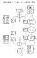
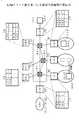
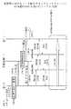
図20は、セルラ通信網における従来の移動パケット通信システムの構成図である。移動パケット通信システムは、移動端末20−1−1〜2、加入者ノード20−2−1〜3、ゲートノード20−3−1〜2及び位置登録サーバ20−4−1〜3により構成され、ゲートノード20−3−1〜2を介して固定網に接続されたISP(インターネットサービスプロバイダ)やユーザ宅内のLAN(ローカルエリアネットワーク)等の固定局装置20−5−1〜2に接続される。
【0004】
位置登録サーバ20−4−1〜3は、移動端末20−1−1〜2の番号(例えばE.164アドレス)の上位桁毎に複数台設置され、各位置登録サーバ20−4−1〜3は、位置登録レジスタ20−6を具備する。なお、E.164はITU−Tで規格化された国際標準の電話番号(端末アドレス)の体系である。
【0005】
位置登録レジスタ20−6は、移動端末20−1−1〜2毎にその現在位置(該移動端末を収容している加入者ノード20−2−1〜3)のアドレス[ADR6〜8]と、移動端末20−1−1〜2が加入契約しているISP又はユーザLANに接続されるゲートノード20−3−1〜2のアドレス[ADR4〜5]とを格納している。
【0006】
各加入者ノード20−2−1〜3及び各ゲートノード20−3−1〜2は、移動端末20−1−1〜2の番号の上位桁から、対応する位置登録サーバ20−4−1〜3のアドレス[ADR1〜3]を検索するためのサーバ検索テーブル20−7を具備する。
【0007】
更に、ゲートノード20−3−1〜2は、外部のISP又はLANから到着したパケットのヘッダ部に格納されているアドレス(即ちIPアドレス)から、移動端末20−1−1〜2の番号に変換するアドレス変換テーブル20−8を具備する。
【0008】
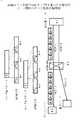
図21は従来の移動パケット通信システムにおける端末移動時の位置登録動作の説明図である。同図において、移動パケット通信システムの構成は図20に示したものと同様であり、同一の符号を付している。位置登録は以下の手順▲1▼〜▲4▼により行なわれる。
【0009】
▲1▼移動端末20−1−1は無線ゾーンの移動に伴い、移動先の無線ゾーンの加入者ノード20−2−1に対して位置登録要求を行う。
▲2▼移動端末20−1−1から位置登録要求メッセージを受けた加入者ノード20−2−1は、該移動端末20−1−1の番号[020−xxx1]の上位桁[020]よりサーバ検索テーブル20−7を用いて対応する位置登録サーバのアドレス[ADR1]を検索する。
【0010】
▲3▼対応する位置登録サーバ20−4−1に位置登録情報(加入者ノード20−2−1のアドレス[ADR6])を転送する。
▲4▼位置登録サーバ20−4−1は、受信した位置登録情報を基に位置登録レジスタ20−6の更新を行う。
【0011】
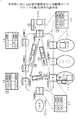
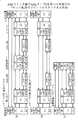
図22はISP又はユーザLAN等の固定局装置20−5−2側から移動端末20−1−1へのパケット転送の動作の説明図である。同図において、移動パケット通信システムの構成は図20に示したものと同様であり、同一の符号を付している。このパケット転送の動作は以下の手順▲1▼〜▲8▼により行なわれる。
【0012】
▲1▼送信先アドレス[1.1.1]のパケットが、ISP又はユーザLAN等の固定局装置20−5−2側からゲートノード20−3−2に到着する。
▲2▼ゲートノード20−3−2は、アドレス変換テーブル20−8により、送信先アドレス[1.1.1]から移動端末の番号[020−xxx1]を検索する。
【0013】
▲3▼更に、ゲートノード20−3−2は、サーバ検索テーブル20−7を用いて検索した移動端末の番号[020−xxx1]から、対応する位置登録サーバ20−4−1のアドレス[ADR1]を検索する。
【0014】
▲4▼ゲートノード1−3−2は、アドレス[ADR1]の位置登録サーバ20−4−1に向けて該当する移動端末の位置情報の通知を要求する。
▲5▼要求を受けた位置登録サーバ20−4−1は、該当する移動端末の番号[020−xxx1]から位置登録レジスタ20−6を検索し、
▲6▼該当する移動端末の位置情報(加入者ノードアドレス=[ADR6])をゲートノード20−3−2に返送する。
【0015】
▲7▼位置情報を受け取ったゲートノード20−3−2は、固定局装置20−5−2側から受け取ったパケットに、移動端末の位置情報(加入者ノードアドレス=[ADR6])を付加して加入者ノード20−2−1に転送する。
【0016】
▲8▼加入者ノードアドレス=[ADR6]の加入者ノード20−2−1は、該パケットを受信し、該パケットから位置情報(加入者ノードアドレス)を削除して送信先移動端末20−1−1へ該パケットを転送する。
【0017】
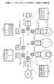
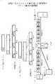
図23は、移動端末20−1−2側からISP又はユーザLAN等の固定局装置20−5−1へのパケット転送の動作の説明図である。同図において、移動パケット通信システムの構成は図20に示したものと同様であり、同一の符号を付している。このパケット転送の動作は以下の手順▲1▼〜▲8▼により行なわれる。
【0018】
▲1▼移動端末20−1−2は加入者ノード20−2−3に通信開始要求を通知する。
▲2▼通信開始要求を受けた加入者ノード20−2−3は、通信開始要求を送出した移動端末の番号[020−xxx2]から、サーバ検索テーブル20−7を用いて対応する位置登録サーバのアドレス[ADR1]を検索する。
【0019】
▲3▼加入者ノード20−2−3は、アドレス[ADR1]の位置登録サーバ20−4−1に向けて、当該移動端末20−1−2が加入契約しているISP又はユーザLANを接続するゲートノード20−3−1〜2のアドレスの通知を要求する。
【0020】
▲4▼要求を受けた位置登録サーバ20−4−1は、位置登録レジスタ20−6を用いて移動端末の番号[020−xxx2]から該当するゲートノードのアドレス[ADR4]を検索し、
▲5▼該当するゲートノードのアドレス[ADR4]を加入者ノード20−2−3に返送する。
【0021】
▲6▼該当するゲートノードのアドレス[ADR4]を受け取った加入者ノード20−2−3は、移動端末20−1−2からのパケットデータにゲートノード20−3−1のアドレス[ADR4]を付加して、当該のゲートノード20−3−1にパケットを転送する。
【0022】
▲7▼ゲートノードアドレス=[ADR4]のゲートノード20−3−1は、該パケットを受信し、ゲートノードアドレスを削除して該パケットを固定局装置20−5−1へ転送する。
【0023】
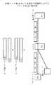
図24は従来の移動パケットシステムと固定局装置との間の通信ルートの説明図である。図の(a)は移動端末から固定局装置へのパケット通信のルートを示し、図の(b)は固定局装置から移動端末へのパケット通信のルートを示している。
【0024】
図の(a)に示すように移動端末24−1から発せられた全てのパケットA,B,Cは、移動パケット網24−2を介し、移動端末毎に定められたゲートノード24−3を必ず経由して固定網24−4のパケットネットワーク(ISP/ユーザLAN)に転送され、そこではじめてパケット毎にルーテイングされ、固定端末、FTP(File Transfer Protocol)、WWW(World Wide Web)等の各送信先プロセスにパケットが転送される。
【0025】
また、図の(b)に示すように、固定網24−4から移動端末24−1へ向かうパケットA,B,Cについても、必ず移動端末毎に定められたゲートノード24−3を経由して、所望の移動端末24−1へ転送される。
【0026】
【発明が解決しようとする課題】
従来の移動パケット通信システムは、移動端末と固定網の特定のISP又はユーザLAN等との間のアクセスラインを提供するが、その前提には、パケット毎にルーテイングを行う固定網が存在する。
【0027】
従って、(1)移動通信網と固定網とを統合する共通のプラットフォームを構築することができないという問題がある。現在では移動通信サービスのキャリアは固定通信サービスを、逆に固定通信サービスのキャリアは移動通信サービスを制度上実施することができないため、個別にプラットフォームを構築するのが一般であるが、将来的にはこのような規制は撤廃される可能性がある。
【0028】
その時、移動通信サービスと固定通信サービスの両方をサポートするキャリアは、移動通信サービス用と固定通信サービス用の2つのプラットフォームを備えなければならず、管理運用が複雑となり、通信サービスのコスト低減を妨げる要因となる。
【0029】
また、(2)前述したように移動通信網と固定網との間で必ず特定のゲートノードを経由することになるので、例えば図25に示すように、実際にはすぐ近くの相手と通信する場合でも、大きく迂回しなければならないケースが起こり得る
。
【0030】
図25は従来の移動パケットシステムと固定網との間の迂回通信ルートの説明図である。同図の(a)は移動端末から固定局装置へのパケット転送の迂回通信ルートを示し、図の(b)は移動端末間パケット転送の迂回通信ルートを示している。
【0031】
図25の(a)に示すように、例えば、横浜に在圏する移動端末25−1−1から移動パケット網25−2と固定網25−4とを介して、例えば、東京、横浜、又は川崎の固定端末、FTP、WWW等の送信先プロセスにパケットA,B,Cを転送する場合、ゲートノード25−3が例えば大坂にあれば、必ず大坂のゲートノード25−3を経由してパケットA,B,Cが転送される。
【0032】
また、図(b)に示すように、例えば横浜に在圏する移動端末25−1−1から同じく横浜に在圏する移動端末25−1−2にパケットA,B,Cを転送する場合でも、大坂に存在するゲートノード25−3を経由してパケットA,B,Cが転送される。
【0033】
このことは、パケット転送の遅延時間を増大させ、通信サービスの品質を低下させるだけでなく、網のトラヒックを圧迫し、他の通信の品質に対しても悪影響を及ぼすといった問題を引き起こす。
【0034】
現在、欧州のETSI(European Telecommunications Standard Institute:欧州電気通信標準化協会)でも移動パケット通信システム(GPRS)の標準化が進められているが、基本的なシステム構成は前述したものと同様であり、従って、同様の問題を含んでいる。
【0035】
一方、インターネットの標準化機関であるIETF(Internet Engineering Task Force )で検討が進められているMobile−IPをベースとした移動パケット通信システムは、既存のインターネットのメカニズムに対し、最少限の変更で移動通信サービスをサポートするメカニズムとして知られている。
【0036】
図26はMobile−IPをベースとした移動パケット通信システムの説明図である。インターネットでは、地域的に閉じた或るエリア(例えばオフイス内)毎に、ドメインが定義されている。IPパケットはドメインまではIPアドレスでルーティングされ、そこからイーサネットバスのMAC(Media Access Control)アドレス等のリンク層のアドレスにより、最終的な端末までパケットが転送される。
【0037】
Moble−IPでは、各ドメイン毎にホームエージェントHA(Home Agent)26−1、及びフォーリンエージェントFA(Foreign Agent )26−2が定義される。各端末は、普段は特定のドメイン(ホームネットワーク)にいることを前提としている。
【0038】
図26に示すように、アドレス[2.2]の移動端末MN(Mobil Node)が他のドメイン(訪問先ネットワーク)へ移動すると、訪問先ネットワーク内のフォーリンエージェントFAを経由して、ホームネットワーク内のホームエージェントHAに移動先のフォーリンエージェントFAのIPアドレス(Care ofAddress:ここでは[3.1])を通知する。
【0039】
アドレス[2.2]の移動端末MN宛のパケットは、一旦ホームネットワーク内のホームエージェントHAで代理受信される。ホームエージェントHAで移動先のフォーリンエージェントFAのIPアドレス[3.1]が付加され、カプセル化して訪問先ネットワークへ転送される。このため、移動端末MN用のIPアドレスの割り当て処理が不要となる。
【0040】
フォーリンエージェントFAでは、付加されたフォーリンエージェントFAのIPアドレスを除去してデカプセル化し、リンク層アドレス(MACアドレス等)で移動端末MNへパケットを配送する。また、移動端末MNからのパケットは、通常のインターネットルールに従い、訪問先ネットワークからダイレクトに転送される。
【0041】
前述したように、Mobile−IPでは既存の固定網でのインターネット通信をベースとしているので、移動通信網と固定網とを統合することが可能である。しかしながら、一旦必ずホームネットワークを経由するので、前述の(2)と同様の問題は残る。
【0042】
更に、Mobile−IPは詳細は割愛するが、もともと高速の移動を考慮していないので、携帯電話システムのような高速の移動には対応できないという問題も広く認識されている。
【0043】
このように、従来の移動パケット通信システムでは、最適なルートを選択しつつ、移動端末と固定局装置網との間のパケット転送を統合する共通のプラットフォームを構築することができなかった。
【0044】
本発明は、これらの問題を解決しようとするものであって、最適なルート選択が可能であるとともに、移動端末と固定局装置との間のパケット転送を共通のプラットフォームにより統合することができる移動パケット通信システムを提供することを目的とする。
【0045】
【課題を解決するための手段】
本発明の移動パケット通信システムは、(1)移動無線通信網により接続される移動端末と、該移動端末を収容する加入者ノードと、インターネットサービスプロバイダ又はローカルエリアネットワークを含む固定局装置と接続されるゲートノードと、パケットの宛先アドレスの上位桁対応に複数台設置される位置登録サーバとから構成され、前記加入者ノード、ゲートノード及び位置登録サーバが相互にネットワークにより接続された移動パケット通信システムであって、
前記各加入者ノード、ゲートノード及び位置登録サーバは、ルーチングのための固有のアドレスを有し、各位置登録サーバは、当該位置登録サーバに対応したパケットの宛先アドレスの上位桁を含むパケットアドレスが付与された移動端末毎に、該移動端末を現在収容している加入者ノードのアドレス、又は該上位桁を含むパケットの宛先アドレスを付与された固定局装置毎に、該固定局装置と接続されるゲートノードのアドレスを格納するレジスタを具備し、前記加入者ノード及び前記ゲートノードは、パケットの宛先アドレスの上位桁から、対応する位置登録サーバのアドレスを検索するテーブルを具備し、移動端末からパケットを受信した加入者ノード又は固定局装置からパケットを受信したゲートノードの発ノードは、該パケットの宛先アドレスの上位桁から対応する位置登録サーバのアドレスを検索し、受信したパケットを該位置登録サーバに転送する手段を備え、
前記位置登録サーバは、受信したパケットの宛先アドレスから、該宛先アドレスに対応した移動端末を収容している加入者ノード、又は該宛先アドレスに対応した固定局装置に接続されるゲートノードの着ノードのアドレスを検索し、検索した着ノードのアドレスを前記発ノードに返送する手段を備え、前記発ノードは、前記位置登録サーバから返送された前記着ノードのアドレスを一時的に保存し、前記移動端末又は前記固定局装置からの同一宛先アドレスの後続のパケットを、前記一時的に保存した着ノードのアドレスを用いて直接着ノードに転送する手段を備えたものである。
【0046】
また、(2)前記位置登録サーバは、前記発ノードから受信したパケットを前記着ノードに転送する手段を備え、前記発ノードは、移動端末又は固定局装置から受信した同一宛先アドレスのパケットの第n(n≧2)番目のパケットであって、前記位置登録サーバから前記着ノードのアドレスが返送された以降の後続のパケットを、前記着ノードに直接転送する手段を備えたものである。
【0047】
また、(3)前記各加入者ノード、ゲートノード及び位置登録サーバは、ルーチングのための固有のインターネットアドレスを有し、前記各加入者ノード、ゲートノード及び位置登録サーバ間のネットワークをルータ網で構成したものである。
【0048】
また、(4)前記各加入者ノード、ゲートノード及び位置登録サーバは、ルーチングのための固有のATMアドレスを有し、前記各加入者ノード、ゲートノード及び位置登録サーバ間のネットワークをATM網の半固定コネクションで構成し、且つ前記各加入者ノード、ゲートノード及び位置登録サーバは、前記パケットをアダプテーションレイヤAALタイプ5のプロトコルを用いて転送する手段を備えたものである。
【0049】
また、(5)前記各加入者ノード、ゲートノード及び位置登録サーバは、ルーチングのための固有のATMアドレスを有し、前記各加入者ノード、ゲートノード及び位置登録サーバ間のネットワークをATM網の半固定コネクションで構成し、且つ前記各加入者ノード、ゲートノード及び位置登録サーバは、前記パケットをアダプテーションレイヤAALタイプ2のプロトコルを用いて転送する手段を備えたものである。
【0050】
また、(6)前記各加入者ノード、ゲートノード及び位置登録サーバは、ルーチングのための固有のアダプテーションレイヤAALタイプ2のアドレスを有し、前記各加入者ノード、ゲートノード及び位置登録サーバ間のネットワークをATM網のアダプテーションレイヤAALタイプ2の半固定コネクションで構成し、且つ前記各加入者ノード、ゲートノード及び位置登録サーバは、前記パケットをアダプテーションレイヤAALタイプ2のプロトコルを用いて転送する手段を備えたものである。
【0051】
また、(7)前記各加入者ノード、ゲートノード及び位置登録サーバは、ルーチングのための固有のATMコネクションレスアドレスを有し、前記各加入者ノード、ゲートノード及び位置登録サーバ間のネットワークをATMコネクションレス網で構成し、且つ前記各加入者ノード、ゲートノード及び位置登録サーバは、前記パケットをアダプテーションレイヤAALタイプ5又はAALタイプ2のプロトコルを用いて転送する手段を備えたものである。
【0052】
また、(8)前記各加入者ノード、ゲートノード及び位置登録サーバ間をATM網のスイッチ切り替え仮想コネクション(SVC)により接続したものである。
【0053】
【発明の実施の形態】
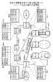
図1は本発明の移動パケット通信システムの構成を示す図である。移動パケット通信システムは、移動無線通信網に接続される移動端末1−1−1〜2、該移動端末1−1−1〜2を収容する加入者ノード1−2−1〜3、固定局装置と接続されるゲートノード1−3−1〜2、移動端末1−1−1〜2の位置を登録する位置登録サーバ1−4−1〜3から構成される。
【0054】
移動端末1−1−1〜2は、ゲートノード1−3−1〜2を介してISP(インターネットサービスプロバイダ)やユーザ宅内のLAN等を含む固定端局装置1−5−1〜2と接続される。
【0055】
位置登録サーバ1−4−1〜3は、移動端末の番号の上位桁毎ではなく、パケットの宛て先アドレス(以下、パケットアドレスという。)の上位桁毎に複数台設置する。ここでパケットアドレスとして、例えばIPv4,IPv6等により規格されたインターネットアドレス(IPアドレス)を使用することができる。
【0056】
なお、IPv4,IPv6(Internet Protocol version 4/6 )は、アドレス空間の拡張とルーティングの負荷の低減を主な目的として改訂されたインターネットプロトコルの標準仕様である。
【0057】
各移動端末1−1−1〜2には、それぞれIPアドレス等のパケットアドレス[1.1.1]、[1.1.2]が割り振られ、またインターネットサービスプロバイダ(ISP)又はユーザLAN等の固定局装置1−5−1〜2には、パケットアドレス[3.1.1〜X]、[3.2.1]が割り振られているものとする。
【0058】
位置登録サーバ1−4−1〜3に設けられる位置登録レジスタ1−6は、それぞれ移動端末対応のパケットアドレス毎に、該移動端末の現在位置(即ち、該移動端末を収容している加入者ノードのアドレス[ADR6〜8])を格納し、また、インターネットサービスプロバイダ又はユーザLAN等の固定局装置対応のパケットアドレス毎に、該固定局装置と接続されているゲートノードのアドレス[ADR4〜5]を格納する。
【0059】
更に、位置登録サーバ1−4−1〜3は、位置登録レジスタ1−6に格納されている加入者ノード又はゲートノードのアドレスを基に、該アドレス先にパケットを転送する機能を具備する。
【0060】
加入者ノード1−2−1〜3及びゲートノード1−3−1〜2には、移動端末1−1−1〜2の番号からではなく、該移動端末1−1−1〜2に対応したパケットアドレスの上位桁から、対応する位置登録サーバのアドレス[ADR1〜3]を検索するサーバ検索テーブル1−7を備えている。
【0061】
図2は本発明における移動端末の位置登録動作の説明図である。同図において、移動パケット通信システムの構成は図1に示したものと同様であり、同一の構成要素には同一符号を付している。移動端末の位置登録動作は以下の手順▲1▼〜▲4▼により行う。
【0062】
▲1▼移動端末1−1−1は無線ゾーンの移動に伴い、移動先の無線ゾーンの加入者ノード1−2−1に対して位置登録要求を行う。
▲2▼移動端末1−1−1からの位置登録要求メッセージを受けた加入者ノード1−2−1は、該移動端末1−1−1に付与されたパケットアドレス[1.1.1]の上位桁[1.X.X]からサーバ検索テーブル1−7を用いて対応する位置登録サーバのアドレス[ADR1]を検索する。ここで、Xは任意の番号を表している。
【0063】
▲3▼加入者ノード1−2−1は、アドレス[ADR1]に対応する位置登録サーバ1−4−1に、位置登録情報(加入者ノード1−2−1のアドレス[ADR6])を転送する。
▲4▼位置登録サーバ1−4−1は、受信した位置登録情報を基に位置登録レジスタ1−6の更新を行う。
【0064】
図3は本発明における固定局装置側から移動端末へのパケットの転送動作の説明図である。同図において、移動パケット通信システムの構成は図1に示したものと同様であり、同一の構成要素には同一符号を付している。
【0065】
インターネットサービスプロバイダ又はユーザLAN等が接続されている固定局装置1−5−2側から移動端末1−1−1へのパケット転送は、以下の手順▲1▼〜▲8▼により行なわれる。
【0066】
▲1▼転送宛先アドレス[1.1.1]のパケットが、インターネットサービスプロバイダ又はユーザLAN等が接続されている固定局装置1−5−2側からゲートノード1−3−2に到着する。
【0067】
▲2▼ゲートノード1−3−2は、サーバ検索テーブル1−7を用いて転送先パケットアドレス[1.1.1]の上位桁[1.X.X]から対応する位置登録サーバのアドレス[ADR1]を検索する。
【0068】
▲3▼ゲートノード1−3−2は、対応する位置登録サーバ1−4−1に向けて、受信したパケットに位置登録サーバのアドレス[ADR1]を付加してパケットを転送する。
【0069】
▲4▼該パケットを受信した位置登録サーバ1−4−1は、位置登録レジスタ1−6を用いて転送先パケットアドレス[1.1.1]から、転送先移動端末を収容している加入者ノードのアドレス[ADR6]を検索する。
【0070】
▲5▼位置登録サーバ1−4−1は、アドレス[ADR6]に対応する加入者ノード1−2−1に向けて、受信したパケットに移動端末の位置情報(加入者ノードアドレス=[ADR6])を付加し直して転送する。
▲6▼更に、位置登録サーバ1−4−1は、検索した移動端末の位置情報(加入者ノードアドレス=[ADR6])を前述のゲートノード1−3−2に返送する。
【0071】
▲7▼ゲートノード1−3−2は受け取った位置情報(加入者ノードアドレス=[ADR6])をキャッシング(一時的に保存)し、固定局装置1−5−2側から受け取る後続のパケットに対しては、キャッシングされた位置情報(加入者ノードアドレス=[ADR6])を読み出してパケットに付加し、加入者ノード1−2−1にダイレクトに転送する。
【0072】
▲8▼位置登録サーバ1−4−1、又はゲートノード1−3−2からパケットを受信した加入者ノード1−2−1は、位置情報(加入者ノードアドレス=[ADR6])を削除し、パケットを移動端末1−1−1へ転送する。
【0073】
図4は、本発明における移動端末から固定局装置側へのパケットの転送動作の説明図である。同図において、移動パケット通信システムの構成は図1に示したものと同様であり、同一の構成要素には同一符号を付している。
【0074】
移動端末1−1−2からインターネットサービスプロバイダ又はユーザLAN等が接続されている固定局装置1−5−1へのパケット転送は、以下の手順▲1▼〜▲8▼により行なわれる。
【0075】
▲1▼転送先パケットアドレス[3.1.1]のパケットが、移動端末1−1−2から加入者ノード1−2−3に到着する。
▲2▼加入者ノード1−2−3は、サーバ検索テーブル1−7を用いて転送先パケットアドレス[3.1.1]の上位アドレス[3.X.X]から対応する位置登録サーバのアドレス[ADR3]を検索する。
【0076】
▲3▼加入者ノード1−2−3は、アドレス[ADR3]に対応する位置登録サーバ1−4−3に向けて、受信したパケットに位置登録サーバのアドレス[ADR3]を付加して転送する。
【0077】
▲4▼該パケットを受信した位置登録サーバ1−4−3は、位置登録レジスタ1−6を用いてパケットアドレス[3.1.1]から対応する配送先のゲートノードのアドレス[ADR4]を検索する。
【0078】
▲5▼位置登録サーバ1−4−3は、アドレス[ADR4]に対応するゲートノード1−3−1に向けて、受信したパケットに配送先情報(ゲートノードアドレス=[ADR4])を付加し直して転送する。
▲6▼更に、位置登録サーバ1−4−3は、検索した配送先情報(ゲートノードアドレス=[ADR4])を前述の加入者ノード1−2−3に返送する。
【0079】
▲7▼加入者ノード1−2−3は、受け取った配送先情報(ゲートノードアドレス=[ADR4])をキャッシングし、移動端末側1−1−2から受け取る後続のパケットに対しては、キャッシングされた配送先情報(加入者ノードアドレス=[ADR4])を読み出してパケットに付加し、ゲートノード1−3−1にダイレクトに転送する。
【0080】
▲8▼位置登録サーバ1−4−3、又は加入者ノード1−2−3からパケットを受信したゲートノード1−3−1は、該配送先情報(ゲ―トノードアドレス=[ADR4])を削除し、パケットを固定局装置1−5−1側へ転送する。
【0081】
このように、固定局装置側から移動端末へのパケット転送と、移動端末から固定局装置側へのパケット転送は、同一体系のパケットアドレスに基づいて同一の動作手順により行うことができる。
【0082】
同一体系のパケットアドレスの移動端末と固定局装置とで扱いが異なるのは、固定局装置に対しては、移動に伴う位置登録の手順が省略される(初期値がそのまま使われる)点だけである。
【0083】
言い換えれば、移動端末同士間のパケット転送や固定局装置同士間のパケット転送も、同様の処理手順で行なうことができる。すなわち、図1乃至図4に示した本発明の構成及び転送動作により、位置登録サーバは最初のパケットのみが経由し後続のパケットは直接に加入者ノード又はゲートノード間の最適な最短ルートで転送することができ、且つ移動端末と固定局装置とを共通のプラットフォームにより接続することができる。
【0084】
なお、加入者ノード又はゲートノード間の最適なルートは、位置登録レジスタ1−6の変更により容易に選択可能である。また、図3及び図4に示したパケット転送において、位置登録サーバは最初のパケットを宛先のノードへ転送し、加入者ノード又はゲートノードは、2番目以降のパケットダイレクトに宛先のノードへ転送したが、位置登録サーバに宛先ノードへのパケット転送機能を備えず、加入者ノード又はゲートノードは、位置登録サーバから宛先ノードのアドレスを受信したのちに最初のパケットから宛先ノードへダイレクトに転送する構成とすることもできる。
【0085】
【実施例】
図5は、ノード間のネットワークとしてIP網(ルータ網)を用いた本発明の実施例の構成図である。この場合、各ノードのアドレスはIP(Internet Protocol )アドレスとなる。
【0086】
図5に示すIP網を用いた実施例は、図1に示した本発明の移動パケット通信システムの各ノードのアドレス[ADR1]〜[ADR8]を、それぞれ各ノード毎に割り振られたIPアドレス[133.1.1]〜[133.1.8]とし、各ノード間をルータ5−1により接続したものである。図5において図1に示した構成と同一の構成要素には同一の符号を付している。
【0087】
また、図5に示す実施例の動作は、図2乃至図4に示した位置登録及びパケット転送の動作において、各ノードのアドレス[ADR1]〜[ADR8]をそれぞれ、各ノード毎のIPアドレス[133.1.1]〜[133.1.8]とすることにより、同様の動作手順で位置登録及びパケット転送の動作が行なわれる。
【0088】
図6は、図5に示すIP網を用いた本発明の実施例におけるノード間のパケット転送の説明図である。同図は加入者ノード6−1からルータ6−2を経由してゲートノード6−3へ転送されるパケットを示している。
【0089】
加入者ノード6−1は、ユーザAパケットに配送先のゲートノードのIPアドレス[α]を付加したパケットAと、ユーザBパケットに同じくIPアドレス[α]を付加したパケットBとを送出する。
【0090】
中継ルータ6−2は、IPアドレス[α]を参照して各パケットを配送先のノードへ転送する。図6は、パケットA及びパケットBのいずれのパケットもゲートノード6−3へ転送される例を示している。
【0091】
図7はIP網を用いた本発明の実施例におけるプロトコルスタックを示す図である。図の(a)はユーザデータの第1番目のパケット転送のプロトコルスタックを示し、図の(b)はユーザデータの第2番目以降のパケット転送のプロトコルスタックを示し、図の(c)は位置登録データのパケット転送のパケットのプロトコルスタックを示している。
【0092】
図の(a)に示すように、第1番目のパケットは位置登録サーバで終端されて転送されるが、第2番目以降のパケットは中継用のルータを介して直接加入者ノード又はゲートノード間で転送される。各ノード、位置登録サーバ及びルータ間は、IPアドレスに基づいてパケットが転送される。
【0093】
図8は、ノード間のネットワークとしてATMスイッチ網を用いた本発明の実施例の構成図である。この実施例は、予め各ノード間をATMスイッチ8−1による半固定コネクション(PVP/PVC)でメッシュリンクにより接続した構成である。この場合、各ノードのアドレスはATMアドレス、即ちVPI/VCI(Virtual Path Identifier /Virtual Channel Identifier)アドレスとなる。
【0094】
図8に示すATMスイッチ網を用いた実施例は、図1に示した本発明の移動パケット通信システムの各ノードのアドレス[ADR1]〜[ADR8]を、それぞれ各ノード毎に割り振られたVPI/VCIアドレス[1]〜[8]としたものである。
【0095】
また、図8に示すATMスイッチ網を用いた実施例の動作は、図2乃至図4に示した位置登録及びパケット転送の動作において、各ノードのアドレス[ADR1]〜[ADR8]をそれぞれ、各ノード毎のVPI/VCIアドレス[1]〜[8]とすることにより、同様の動作手順で位置登録及びパケット転送の動作が行なわれる。
【0096】
ノード間のネットワークにATMスイッチ網を用いる場合、アダプテーションレイヤとして、AALタイプ5及びAALタイプ2のプロトコルを使用した実施例を以下に説明する。
【0097】
AALタイプ5は、コネクション型データ又はコネクションレス型データのパケットをATMセル化するためのアダプテーションレイヤで、AALタイプ3又はAALタイプ4に比べてオーバヘッドを削減した簡易なプロトコルである。
【0098】
また、AALタイプ2は、パケット化されたビデオ信号やオーディオ信号等のパケットを、発着間のタイミング関係を保存しながら転送するアダプテーションレイヤのプロトコルで、可変長のパケットをATMセルに分解し、またその逆に組み立てる機能を有する。
【0099】
図9は、ATMスイッチ網でAALタイプ5を用いた本発明のノード間のパケット転送の説明図である。同図は加入者ノード9−1からATMスイッチ(ATM−SW)9−2を経由してゲートノード9−3へ転送されるパケットを示している。
【0100】
加入者ノード9−1は、ユーザAパケット及びユーザBパケットに対して、それぞれATMセルA−1〜3、ATMセルB−1〜3に分割し、それぞれのATMセルに目的のゲートノード9−3への仮想チャネルの識別子であるATMアドレス(VCI=[1])を付加して送出する。
【0101】
なお、ユーザAパケット又はユーザBパケットの最終データを格納したATMセルA−3又はB−3には、そのヘッダ部のペイロードタイプ表示ビットに最終セルである旨が表示される。
【0102】
中継用のATMスイッチ(ATM−SW)9−2は、ATMアドレスであるVCIの値を参照して各ATMセルを目的のノードへ転送する。図9では、ATMセルA−1〜3及びATMセルB−1〜3のいずれのATMセルもゲートノード9−3へ転送される例を示している。
【0103】
ゲートノード9−3では、加入者ノード9−1とは逆の手順により、ATMセルA−1〜3、ATMセルB−1〜3から元のユーザAパケット及びユーザBパケットを再生する。
【0104】
ここで、VCI=[1]の1本の仮想チャネルで二つのユーザパケットを転送するので、着側のゲートノード9−3で正しくパケットを再生するためには、発側の加入者ノード9−1では、一つのユーザAパケットを分解したATMセルA−1〜3を全て送出した後、ユーザBパケットを分解したATMセルB−1〜3を送出する必要がある。
【0105】
その理由は、着側のゲートノード9−3は受信したATMセル自体からは、ユーザAパケットのATMセルかユーザBパケットのATMセルかを区別することができず、パケットの最終データを格納したATMセルが識別されるだけであるからである。
【0106】
図10はATMスイッチ網でAALタイプ5を用いた本発明のパケット転送のプロトコルスタックを示す図である。図の(a)はユーザデータの第1番目のパケット転送のプロトコルスタックを示し、図の(b)はユーザデータの第2番目以降のパケット転送のプロトコルスタックを示し、図の(c)は位置登録データのパケット転送のパケットのプロトコルスタックを示している。
【0107】
図の(a)に示すように、第1番目のパケットは位置登録サーバを経由して転送されるが、第2番目以降の送信パケットは中継用のATMスイッチ(ATM−SW)を介して直接加入者ノード又はゲートノードにATMアドレスに基づいて転送される。また、位置登録データのパケットは図の(c)に示すようにATMアドレスに基づいて位置登録サーバに転送される。
また、加入者ノード、ゲートノード及び位置登録サーバは、アダプテーションレイヤタイプ5のプロトコルを終端する機能を備えている。
【0108】
図11は、ATMスイッチ網でAALタイプ2を用いた本発明のノード間のパケット転送の説明図である。同図は加入者ノード11−1からATMスイッチ(ATM−SW)11−2を経由してゲートノード11−3へ転送されるパケットを示している。
【0109】
加入者ノード11−1では、ユーザAパケット及びユーザBパケットを、それぞれ可変長のショートセル(AAL)A−1〜3及びショートセル(AAL)B−1〜3に分割し、ユーザAパケットの各ショートセルA−1〜3にコネクション識別子(CID=[A])を付加し、ユーザBパケットの各ショートセルB−1〜3にコネクション識別子(CID=[B])を付加した後、同一の目的ノードへ向かうショートセルA−1〜3、B−1〜3を、53バイト長のATMセルに多重し、目的のゲートノード11−3のATMアドレス(VCI=[1])を付加して送出する。
【0110】
中継用のATMスイッチ(ATM−SW)11−2は、ATMアドレスであるVCIの値を見て各ATMセルを目的のノードへ転送するのは、図9に示した実施例の場合と同様である。
【0111】
ゲートノード11−3では、加入者ノード11−1とは逆の手順により、受信したATMセルからコネクション識別子(CID)を基にユーザAパケットとユーザBパケットとを識別し、元のユーザAパケットとユーザBパケットとを再生する。
【0112】
AALタイプ2のアダプテーションレイヤプロトコルを使用する場合は、コネクション識別子(CID)を用いて1本の仮想チャネル(VC)中に、異なるユーザのショートセルを多重して転送することができる。
【0113】
従って、ショートセル毎のインタリーブ多重が可能となり、図9に示したAALタイプ5を用いたパケット転送に比べて、他のパケットのATMセルによる送出完了の待ち合わせによる転送遅延の短縮を図ることができる。
【0114】
図12はATMスイッチ網でAALタイプ2を用いた本発明のパケット転送のプロトコルスタックを示す図である。図の(a)はユーザデータの第1番目のパケット転送のプロトコルスタックを示し、図の(b)はユーザデータの第2番目以降のパケット転送のプロトコルスタックを示し、図の(c)は位置登録データのパケット転送のパケットのプロトコルスタックを示している。
【0115】
図12に示すプロトコルスタックは、図10に示すAALタイプ5を用いた実施例のプロトコルスタックを、アダプテーションレイヤのAALタイプ2のものに置き換えたものである。
【0116】
図13はノード間のネットワークとしてAALスイッチ網を用いた本発明の実施例の構成図である。この実施例は、ノード間のネットワーク内にアダプテーションレイヤAALタイプ2のセルをスイッチングするアダプテーションレイヤスイッチ(AAL−SW)13−1を設置し、AALタイプ2のレベルで各ノード間をメッシュリンクにより接続したものである。
【0117】
この実施例において、各ノードはアダプテーションレイヤAALタイプ2によりセルを転送する。この場合、各ノードのアドレスは、アダプテーションレイヤAALタイプ2のアドレス、即ちVPI/VCI/CID(Virtual Path Identifier /Virtual Channel Identifier/Connection Identifier )アドレスとなる。
【0118】
図13に示す実施例は、図8に示したATMスイッチ網を用いた実施例のATMスイッチ(ATM−SW)8−1を前述のアダプテーションレイヤスイッチ(AAL−SW)13−1に置き換え、また、移動パケット通信システムの各ノードのアドレス[ADR1]〜[ADR8]を、それぞれ各ノード毎に割り振られたVPI/VCI/CIDアドレス[1]〜[8]としたものである。
【0119】
図14は、AALスイッチ網でAALタイプ2を用いた本発明のパケット転送の説明図である。同図は加入者ノード14−1から前述のアダプテーションレイヤスイッチ(AAL−SW)14−2を経由してゲートノード14−3,14−4へ転送されるパケットを示している。
【0120】
加入者ノード14−1では、図11に示した実施例と同様に、ユーザAパケット及びユーザBパケットを、それぞれ可変長のショートセル(AAL)A−1〜3及びB−1〜3に分割し、ユーザAパケットの各ショートセルA−1〜3にコネクション識別子(CID=[A])を付加し、ユーザBパケットの各ショートセルB−1〜3にコネクション識別子(CID=[B])を付加した後、同一のアダプテーションレイヤスイッチ(AAL−SW)14−2へ向かうショートセルA−1〜3、B−1〜3を、53バイト長のATMセルに多重し、ATMアドレスとして、アダプテーションレイヤスイッチ(AAL−SW)のVCI=[1]を付加して送出する。
【0121】
中継点のアダプテーションレイヤスイッチ(AAL−SW)14−2は、ATMアドレスである仮想チャネル識別子(VCI)及びコネクション識別子(CID)の値を参照して各ショートセルを目的のノードへ転送する。
【0122】
図14に示した例では、CID=[A]即ちユーザAパケットは、ゲートノード14−3へ転送し、CID=[B]即ちユーザBパケットは、他のノード14−4へ転送する。
【0123】
ゲートノード14−3及びゲートノード14−4では、加入者ノード14−1とは逆の手順により、受信したショートセルA−1〜3から元のパケットAを再生する。
【0124】
この図14に示したAALスイッチ網でAALタイプ2を用いた場合、コネクション識別子(CID)は転送先のアドレスとなり、図11に示した実施例と比べて待ち合わせ遅延時間の短縮は図れないが、コネクション識別子CIDの分だけ各ノードのアドレス領域が増えることになるので、より大規模なネットワークへの対応が可能となる。
【0125】
図15はAALスイッチ網でAALタイプ2を用いた本発明のパケット転送のプロトコルスタックを示す図である。図の(a)はユーザデータの第1番目のパケット転送のプロトコルスタックを示し、図の(b)はユーザデータの第2番目以降のパケット転送のプロトコルスタックを示し、図の(c)は位置登録データのパケット転送のパケットのプロトコルスタックを示している。
【0126】
図15に示すプロトコルスタックは、図12に示したATMスイッチ網を用いた実施例のプロトコルスタックに対して、アダプテーションレイヤのAALタイプ2を終端する機能を有するアダプテーションスイッチ(AAL−SW)が備えられている。
【0127】
図16は、ノード間のネットワークとしてATMコネクションレス網を用いた本発明の実施例の構成図である。この実施例は、ノード間のネットワーク内にATMコネクションレスサーバ16−1を設置し、ATMコネクションレスアドレスのレベルでノード間をメッシュリンクにより接続したものである。
【0128】
この場合、各ノードのアドレスはATMコネクションレスアドレスとなる。各ノードのATMコネクションレスアドレスは、例えば、E.164やIPv6により規定されたアドレス等を用いることができる。
【0129】
図16に示す実施例は、図1に示した本発明の移動パケット通信システムの各ノードのアドレス[ADR1]〜[ADR8]を、それぞれ各ノード毎に割り振られたATMコネクションレスアドレス[1]〜[8]とすることにより実現される。
【0130】
また、図16に示す実施例の動作は、図2乃至図4に示した位置登録及びパケット転送の動作において、各ノードのアドレス[ADR1]〜[ADR8]をそれぞれ、各ノード毎のATMコネクションレスアドレス[1]〜[8]とすることにより、同様の動作手順で位置登録及びパケット転送の動作が行なわれる。
【0131】
図17は、ATMコネクションレス網を用いた本発明のパケット転送の説明図である。同図は加入者ノード17−1からATMコネクションレスサーバ(CLS)17−2を経由してゲートノード17−3へ、アダプテーションレイAALタイプ5により転送されるパケットを示している。
【0132】
加入者ノード17−1は、ユーザAパケット及びユーザBパケットに対して、目的のゲートノード17−3のIPアドレス[α]を付加した後、ATMセルに分割し、それぞれに目的のゲートノードのATMアドレスVCI=[1]を付加して送出する。
【0133】
中継局のATMコネクションレスサーバ(CLS)17−2は、コネクションレスアドレス値[α]を参照して、後続の各ATMセルを目的のノードへ転送する。図では、ユーザAパケット及びユーザBパケットのいずれのパケットのATMセルもゲートノード17−3へ転送される例を示している。
ゲ−トノード17−3では、加入者ノード17−1とは逆の手順により、受信したATMセルから元のユーザAパケット及びユーザBパケットを再生する。
【0134】
この図17に示した実施例は、図11に示したATMスイッチ網でAALタイプ2を用いた実施例に比べて、待ち合わせ遅延時間の短縮は図れないが、コネクションレスアドレスの分だけ各ノードのアドレス領域が増えることになるので、より大規模なネットワークへの対応が可能となる。
【0135】
図18はATMコネクションレス網を用いた本発明のパケット転送のプロトコルスタックを示す図である。図の(a)はユーザデータの第1番目のパケット転送のプロトコルスタックを示し、図の(b)はユーザデータの第2番目以降のパケット転送のプロトコルスタックを示し、図の(c)は位置登録データのパケット転送のパケットのプロトコルスタックを示している。
【0136】
図18に示すプロトコルスタックは、加入者ノード、位置登録サーバ及びゲートノードにおけるこれまでの実施例のレイヤL2のSSCOP(Service Specific Connection Oriented Protocol )に代えてTCP,IPを採用し、ATMコネクションレスサーバ(CLS)に、アダプテーションレイヤALL5とIPのプロトコルの終端機能を備えたものである。
【0137】
図19は本発明におけるノード間のダイレクトコネクションにATM網のSVCを用いたシーケンス図である。
発ノードは、ユーザAパケットを受信すると(19−1)、位置登録サーバを検索し(19−2)、位置登録サーバに該パケットを転送する(19−3)。
【0138】
位置登録サーバは位置情報を検索し(19−4)、着ノードにパケットを転送する(19−5)とともに、着ノードアドレスを発ノードに返送する(19−6)。また、着ノードは位置登録サーバから受信した第1番目のパケットを送信宛先に送信する(19−7)。
【0139】
発ノードは、着ノードアドレスを受け取ると、ATMスイッチ(ATM−SW)を介して着ノードに向かうコネクションの設定(Set−up)を行ない(19−8)、着ノード側からその確認(Ack)が返送され(19−9)、コネクションが確立される。
【0140】
その後、発ノードから着ノードに確立されたコネクションを介してパケットを転送する(19−10)。
図15〜図18に示した実施例は、いずれもノード間のコネクションを複数のユーザが共用しているので、各ユーザ毎に個別のQoS(Quality of Service)を提供することは困難である。
【0141】
一方、図19に示すATM網におけるスイッチ切り替え仮想コネクションSVC(Switched Virtual Connection )の確立手順を用いて、ユーザ毎に個別のコネクションを設定する場合は、各ユーザ個別のQoSを満足することが可能となる。
【0142】
なお、スイッチ切り替え仮想コネクションSVCは、アダプテーションレイヤAALタイプ5を用いて仮想チャネル(VC)レベルで設定することも、また、帯域保証の必要がある場合、アダプテーションレイヤAALタイプ2を用いてアダプテーションレイヤ(AAL)レベルで設定することもできる。
【0143】
【発明の効果】
以上説明したように本発明によれば、位置登録サーバは、パケットアドレスが付与された移動端末毎に、該移動端末を収容している加入者ノードのアドレスを格納し、発ノードは、位置登録サーバから通知される着ノードのアドレスを一時的に保存し、該一時的に保存した着ノードのアドレスを用いて、後続のパケットを着ノードに直接転送することにより、パケット転送の最適なルートが選択されるとともに、移動端末と固定局装置との間のパケット転送を共通のプラットフォームにより統合することができる。
【図面の簡単な説明】
【図1】本発明の移動パケット通信システムの構成を示す図である。
【図2】本発明における移動端末の位置登録動作の説明図である。
【図3】本発明における固定局装置側から移動端末へのパケットの転送動作の説明図である。
【図4】本発明における移動端末から固定局装置側へのパケットの転送動作の説明図である。
【図5】IP網(ルータ網)を用いた本発明の実施例の構成図である。
【図6】IP網(ルータ網)を用いた本発明の実施例におけパケット転送の説明図である。
【図7】IP網(ルータ網)を用いた本発明の実施例におけるプロトコルスタックを示す図である。
【図8】ATMスイッチ網を用いた本発明の実施例の構成図である。
【図9】ATMスイッチ網でAALタイプ5を用いた本発明のノード間のパケット転送の説明図である。
【図10】ATMスイッチ網でAALタイプ5を用いた本発明のパケット転送のプロトコルスタックを示す図である。
【図11】ATMスイッチ網でAALタイプ2を用いた本発明のノード間のパケット転送の説明図である。
【図12】ATMスイッチ網でAALタイプ2を用いた本発明のパケット転送のプロトコルスタックを示す図である。
【図13】AALスイッチ網を用いた本発明の実施例の構成図である。
【図14】AALスイッチ網でAALタイプ2を用いた本発明のパケット転送の説明図である。
【図15】AALスイッチ網でAALタイプ2を用いた本発明のパケット転送のプロトコルスタックを示す図である。
【図16】ATMコネクションレス網を用いた本発明の実施例の構成図である。
【図17】ATMコネクションレス網を用いた本発明のパケット転送の説明図である。
【図18】ATMコネクションレス網を用いた本発明のパケット転送のプロトコルスタックを示す図である。
【図19】本発明におけるノード間のダイレクトコネクションにATM網のSVCを用いたシーケンス図である。
【図20】セルラ通信網における従来の移動パケット通信システムの構成図である。
【図21】従来の移動パケット通信システムにおける端末移動時の位置登録動作の説明図である。
【図22】従来の固定局装置側から移動端末へのパケット転送の動作の説明図である。
【図23】従来の移動端末側から固定局装置へのパケット転送の動作の説明図である。
【図24】従来の移動パケットシステムと固定局装置との間の通信ルートの説明図である。
【図25】従来の移動パケットシステムと固定網との間の迂回通信ルートの説明図である。
【図26】Mobile−IPをベースとした移動パケット通信システムの説明図である。
【符号の説明】
1−1−1〜2 移動端末
1−2−1〜3 加入者ノード
1−3−1〜2 ゲートノード
1−4−1〜3 位置登録サーバ
1−5−1〜2 固定局装置
1−6 位置登録レジスタ
1−7 サーバ検索テーブル[0001]
BACKGROUND OF THE INVENTION
The present invention relates to a mobile packet communication system that supports data communication such as Internet communication in a high-speed mobile communication system such as a cellular communication network. Currently, studies on next-generation mobile communication systems are being promoted by research institutions and standardization organizations around the world, and next-generation mobile communication systems will provide multimedia communication services including high-speed data communication up to about 2 Mbps. want to be.
[0002]
In particular, packet communication services such as the Internet are expected to become core communication services in next-generation mobile communication systems, replacing current voice-centric communication services, and are connected to mobile radio communication networks. A communication network that integrates a mobile terminal and a fixed station apparatus including an ISP (Internet Service Provider) and a LAN in a user's home has also been started.
[0003]
[Prior art]
FIG. 20 is a configuration diagram of a conventional mobile packet communication system in a cellular communication network. The mobile packet communication system includes mobile terminals 20-1-1-2, subscriber nodes 20-2-1-3, gate nodes 20-3-1-2, and location registration servers 20-4-1-3. Are connected to fixed station apparatuses 20-5-1 and 20-2 such as ISP (Internet Service Provider) and user home LAN (local area network) connected to the fixed network via gate nodes 20-3-1-2. The
[0004]
A plurality of the location registration servers 20-4-1 to 20-3 are installed for each upper digit of the numbers (for example, E.164 addresses) of the mobile terminals 20-1-1-2. 3 includes a location registration register 20-6. In addition, E.I. Reference numeral 164 denotes an international standard telephone number (terminal address) system standardized by ITU-T.
[0005]
The location registration register 20-6 includes the address [ADR6-8] of the current location (subscriber node 20-2-1-3 that accommodates the mobile terminal) for each of the mobile terminals 20-1-1-2. The address [ADR4-5] of the gate nodes 20-3-1 and 2 connected to the ISP or the user LAN to which the mobile terminals 20-1-1-2 are subscribed is stored.
[0006]
Each of the subscriber nodes 20-2-1 to 20-1-2 and the gate nodes 20-3-1 to 20-2 corresponds to the corresponding location registration server 20-4-1 from the upper digit of the number of the mobile terminal 20-1-1-2. And a server search table 20-7 for searching for addresses [ADR1 to 3].
[0007]
Furthermore, the gate nodes 20-3-1 and 2-2 change the numbers of the mobile terminals 20-1-1-2 from the addresses (that is, the IP addresses) stored in the header part of the packets arriving from the external ISP or LAN. An address conversion table 20-8 for conversion is provided.
[0008]
FIG. 21 is an explanatory diagram of a location registration operation when a terminal moves in a conventional mobile packet communication system. In this figure, the configuration of the mobile packet communication system is the same as that shown in FIG. 20, and is given the same reference numerals. Location registration is performed by the following procedures (1) to (4).
[0009]
(1) The mobile terminal 20-1-1 makes a location registration request to the subscriber node 20-2-1 of the destination wireless zone as the wireless zone moves.
{Circle around (2)} The subscriber node 20-2-1 that has received the location registration request message from the mobile terminal 20-1-1 starts from the upper digits [020] of the number [020-xxx1] of the mobile terminal 20-1-1. The address [ADR1] of the corresponding location registration server is searched using the server search table 20-7.
[0010]
(3) The location registration information (subscriber node 20-2-1 address [ADR6]) is transferred to the corresponding location registration server 20-4-1.
(4) The location registration server 20-4-1 updates the location registration register 20-6 based on the received location registration information.
[0011]
FIG. 22 is an explanatory diagram of the packet transfer operation from the fixed station device 20-5-2 side such as ISP or user LAN to the mobile terminal 20-1-1. In this figure, the configuration of the mobile packet communication system is the same as that shown in FIG. 20, and is given the same reference numerals. This packet transfer operation is performed by the following procedures (1) to (8).
[0012]
(1) A packet with a destination address [1.1.1] arrives at the gate node 20-3-2 from the fixed station apparatus 20-5-2 side such as ISP or user LAN.
(2) The gate node 20-3-2 searches the mobile terminal number [020-xxx1] from the transmission destination address [1.1.1] by using the address conversion table 20-8.
[0013]
(3) Further, the gate node 20-3-2 determines the address [ADR1] of the corresponding location registration server 20-4-1 from the number [020-xxx1] of the mobile terminal searched using the server search table 20-7. ] Is searched.
[0014]
(4) The gate node 1-3-2 requests the location registration server 20-4-1 of the address [ADR1] to notify the location information of the corresponding mobile terminal.
(5) Upon receiving the request, the location registration server 20-4-1 searches the location registration register 20-6 from the number [020-xxx1] of the corresponding mobile terminal,
{Circle around (6)} Position information (subscriber node address = [ADR6]) of the corresponding mobile terminal is returned to the gate node 20-3-2.
[0015]
(7) The gate node 20-3-2 receiving the location information adds the location information of the mobile terminal (subscriber node address = [ADR6]) to the packet received from the fixed station device 20-5-2. To the subscriber node 20-2-1.
[0016]
(8) The subscriber node 20-2-1 with the subscriber node address = [ADR6] receives the packet, deletes location information (subscriber node address) from the packet, and transmits to the destination mobile terminal 20-1. Transfer the packet to -1.
[0017]
FIG. 23 is an explanatory diagram of the operation of packet transfer from the mobile terminal 20-1-2 side to the fixed station apparatus 20-5-1 such as ISP or user LAN. In this figure, the configuration of the mobile packet communication system is the same as that shown in FIG. 20, and is given the same reference numerals. This packet transfer operation is performed by the following procedures (1) to (8).
[0018]
(1) The mobile terminal 20-1-2 notifies the communication start request to the subscriber node 20-2-3.
(2) The subscriber node 20-2-3 that has received the communication start request uses the server search table 20-7 to search for the corresponding location registration server from the number [020-xxx2] of the mobile terminal that has transmitted the communication start request. The address [ADR1] is searched.
[0019]
(3) The subscriber node 20-2-3 connects the ISP or user LAN to which the mobile terminal 20-1-2 has a subscription contract to the location registration server 20-4-1 of the address [ADR1]. The notification of the address of the gate node 20-3-1-2 is requested.
[0020]
(4) The location registration server 20-4-1 that has received the request searches the address [ADR4] of the corresponding gate node from the mobile terminal number [020-xxx2] using the location registration register 20-6.
(5) The address [ADR4] of the corresponding gate node is returned to the subscriber node 20-2-3.
[0021]
(6) The subscriber node 20-2-3 that has received the address [ADR4] of the corresponding gate node assigns the address [ADR4] of the gate node 20-3-1 to the packet data from the mobile terminal 20-1-2. In addition, the packet is transferred to the gate node 20-3-1 concerned.
[0022]
(7) The gate node 20-3-1 having the gate node address = [ADR4] receives the packet, deletes the gate node address, and transfers the packet to the fixed station apparatus 20-5-1.
[0023]
FIG. 24 is an explanatory diagram of a communication route between a conventional mobile packet system and a fixed station apparatus. (A) of the figure shows the route of packet communication from the mobile terminal to the fixed station apparatus, and (b) of the figure shows the route of packet communication from the fixed station apparatus to the mobile terminal.
[0024]
As shown in (a) of the figure, all packets A, B, and C transmitted from the mobile terminal 24-1 pass through the mobile packet network 24-2 to the gate node 24-3 determined for each mobile terminal. The packet is always transferred to the packet network (ISP / user LAN) of the fixed network 24-4, and is routed for each packet for the first time. Each transmission of fixed terminal, FTP (File Transfer Protocol), WWW (World Wide Web), etc. The packet is transferred to the destination process.
[0025]
Also, as shown in (b) of the figure, packets A, B, and C going from the fixed network 24-4 to the mobile terminal 24-1 always pass through the gate node 24-3 determined for each mobile terminal. To the desired mobile terminal 24-1.
[0026]
[Problems to be solved by the invention]
A conventional mobile packet communication system provides an access line between a mobile terminal and a specific ISP of a fixed network or a user LAN, and there is a fixed network that performs routing for each packet.
[0027]
Therefore, (1) there is a problem that a common platform for integrating the mobile communication network and the fixed network cannot be constructed. Currently, mobile communication service carriers are unable to systematically implement fixed communication services, and vice versa, mobile communication services are generally not systematically implemented. Such restrictions may be abolished.
[0028]
At that time, carriers that support both mobile communication services and fixed communication services must have two platforms for mobile communication services and fixed communication services, which complicates management operations and hinders cost reduction of communication services. It becomes a factor.
[0029]
(2) As described above, since a specific gate node is always passed between the mobile communication network and the fixed network, for example, as shown in FIG. Even if you have to make a big detour
.
[0030]
FIG. 25 is an explanatory diagram of a bypass communication route between a conventional mobile packet system and a fixed network. (A) of the figure shows a detour communication route for packet transfer from the mobile terminal to the fixed station apparatus, and (b) of the diagram shows a detour communication route for packet transfer between mobile terminals.
[0031]
As shown in (a) of FIG. 25, for example, from the mobile terminal 25-1-1 located in Yokohama, via the mobile packet network 25-2 and the fixed network 25-4, for example, Tokyo, Yokohama, or When transferring packets A, B, and C to a destination process such as a fixed terminal in Kawasaki, FTP, or WWW, if the gate node 25-3 is in Osaka, for example, the packet must be sent via the gate node 25-3 in Osaka. A, B, and C are transferred.
[0032]
Further, as shown in FIG. 2B, for example, even when packets A, B, and C are transferred from the mobile terminal 25-1-1 located in Yokohama to the mobile terminal 25-1-2 also located in Yokohama. Packets A, B, and C are transferred via the gate node 25-3 existing in Osaka.
[0033]
This not only increases the delay time of packet transfer and lowers the quality of communication services, but also causes problems such as squeezing network traffic and adversely affecting the quality of other communications.
[0034]
At present, standardization of the mobile packet communication system (GPRS) is also being promoted in European ETSI (European Telecommunications Standard Institute), but the basic system configuration is the same as described above. Includes similar issues.
[0035]
On the other hand, Mobile-IP-based mobile packet communication systems, which are being studied by the Internet Engineering Task Force (IETF), which is an Internet standardization organization, are mobile communication systems with minimal changes to existing Internet mechanisms. Known as a mechanism to support services.
[0036]
FIG. 26 is an explanatory diagram of a mobile packet communication system based on Mobile-IP. In the Internet, a domain is defined for each certain area (for example, in an office) that is closed locally. The IP packet is routed to the domain by an IP address, and from there, the packet is transferred to the final terminal by a link layer address such as a MAC (Media Access Control) address of the Ethernet bus.
[0037]
In Mobile-IP, a home agent HA (Home Agent) 26-1 and a foreign agent FA (Foreign Agent) 26-2 are defined for each domain. Each terminal is usually assumed to be in a specific domain (home network).
[0038]
As shown in FIG. 26, when the mobile terminal MN (Mobil Node) with the address [2.2] moves to another domain (visited network), it passes through the foreign agent FA in the visited network, The home agent HA is notified of the IP address of the destination foreign agent FA (Care of Address: [3.1] in this case).
[0039]
The packet addressed to the mobile terminal MN having the address [2.2] is temporarily received by the home agent HA in the home network. The IP address [3.1] of the destination foreign agent FA is added by the home agent HA, encapsulated and transferred to the visited network. This eliminates the need for IP address assignment processing for the mobile terminal MN.
[0040]
The foreign agent FA removes and decapsulates the IP address of the added foreign agent FA, and delivers the packet to the mobile terminal MN with a link layer address (MAC address or the like). Further, the packet from the mobile terminal MN is directly transferred from the visited network in accordance with normal Internet rules.
[0041]
As described above, since Mobile-IP is based on Internet communication in an existing fixed network, it is possible to integrate the mobile communication network and the fixed network. However, since it always goes through the home network, the same problem as the above (2) remains.
[0042]
Further, Mobile-IP omits details, but since it does not consider high-speed movement from the beginning, the problem that it cannot cope with high-speed movement such as a mobile phone system is widely recognized.
[0043]
Thus, in the conventional mobile packet communication system, it has been impossible to construct a common platform that integrates packet transfer between a mobile terminal and a fixed station apparatus network while selecting an optimal route.
[0044]
The present invention is intended to solve these problems, and it is possible to select an optimum route, and to move the packet transfer between the mobile terminal and the fixed station apparatus by a common platform. An object is to provide a packet communication system.
[0045]
[Means for Solving the Problems]
The mobile packet communication system of the present invention is connected to (1) a mobile terminal connected by a mobile radio communication network, a subscriber node accommodating the mobile terminal, and a fixed station apparatus including an Internet service provider or a local area network. Mobile node communication system, and a plurality of location registration servers installed corresponding to the upper digits of the destination address of the packet, and the subscriber node, the gate node and the location registration server are connected to each other via a network Because
Each of the subscriber nodes, the gate node, and the location registration server has a unique address for routing, and each location registration server has a packet address including the upper digits of the destination address of the packet corresponding to the location registration server. Each assigned mobile terminal is connected to the fixed station apparatus for each fixed station apparatus to which an address of a subscriber node that currently accommodates the mobile terminal or a destination address of a packet including the upper digit is assigned. A register for storing the address of the gate node, and the subscriber node and the gate node have a table for retrieving the address of the corresponding location registration server from the upper digits of the destination address of the packet. The originating node of the gate node that received the packet from the subscriber node or fixed station apparatus that received the packet Searches the address of the location registering server corresponding the significant digit of the previous address, the received packet includes means for transferring to the location registering server,
The location registration server is a destination node of a received packet, a subscriber node accommodating a mobile terminal corresponding to the destination address, or a destination node of a gate node connected to a fixed station apparatus corresponding to the destination address Means for retrieving the address of the destination node, and returning the address of the retrieved destination node to the source node, wherein the source node temporarily stores the address of the destination node returned from the location registration server, and Means for transferring a subsequent packet of the same destination address from the terminal or the fixed station apparatus directly to the destination node using the temporarily stored destination node address.
[0046]
(2) The location registration server includes means for transferring a packet received from the source node to the destination node, and the source node is configured to transfer a packet of the same destination address received from a mobile terminal or a fixed station device. An n-th packet (n ≧ 2) is provided, and means for directly transferring a subsequent packet after the address of the destination node is returned from the location registration server to the destination node.
[0047]
(3) Each subscriber node, gate node and location registration server has a unique Internet address for routing, and a network between each subscriber node, gate node and location registration server is a router network. It is composed.
[0048]
(4) Each subscriber node, gate node and location registration server has a unique ATM address for routing, and the network between each subscriber node, gate node and location registration server is an ATM network. Each of the subscriber nodes, the gate nodes, and the location registration server is configured with a semi-fixed connection, and includes means for transferring the packet using an adaptation
[0049]
(5) Each subscriber node, gate node and location registration server has a unique ATM address for routing, and the network between each subscriber node, gate node and location registration server is an ATM network. Each of the subscriber nodes, the gate nodes, and the location registration server is configured with a semi-fixed connection, and includes means for transferring the packet using an adaptation
[0050]
(6) Each subscriber node, gate node and location registration server has a unique adaptation
[0051]
(7) Each subscriber node, gate node and location registration server has a unique ATM connectionless address for routing, and the network between each subscriber node, gate node and location registration server is ATM. Each of the subscriber nodes, the gate nodes, and the location registration server is configured by a connectionless network, and includes means for transferring the packet using an adaptation
[0052]
(8) Each subscriber node, gate node, and location registration server are connected by an ATM network switching virtual connection (SVC).
[0053]
DETAILED DESCRIPTION OF THE INVENTION
FIG. 1 is a diagram showing a configuration of a mobile packet communication system according to the present invention. The mobile packet communication system includes mobile terminals 1-1-1 and 1-2 connected to a mobile radio communication network, subscriber nodes 1-2-1 to 1-3 that accommodate the mobile terminals 1-1-1 and 2, fixed stations. It is composed of location registration servers 1-4-1-3 for registering the locations of the gate nodes 1-3-1-2 and the mobile terminals 1-1-1-2 connected to the apparatus.
[0054]
The mobile terminals 1-1-1 and 2 are connected to the fixed terminal devices 1-5-1 and 2 including ISP (Internet service provider) and user home LAN via the gate nodes 1-3-1 and 2. Is done.
[0055]
A plurality of location registration servers 1-4-1-3 are installed not for each upper digit of the mobile terminal number but for each upper digit of the packet destination address (hereinafter referred to as a packet address). Here, as a packet address, for example, an Internet address (IP address) standardized by IPv4, IPv6, or the like can be used.
[0056]
Note that IPv4 and IPv6 (
[0057]
Packet addresses [1.1.1] and [1.1.2] such as IP addresses are allocated to the mobile terminals 1-1-1 and 1-2, respectively, and an Internet service provider (ISP) or a user LAN is assigned Packet addresses [3.1.1 to X] and [3.2.1] are assigned to the fixed station apparatuses 1-5-1 to 1-2-1.
[0058]
The location registration registers 1-6 provided in the location registration servers 1-4-1 to 1-3 store the current location of the mobile terminal (that is, the subscriber accommodating the mobile terminal) for each packet address corresponding to the mobile terminal. Node address [ADR6 to 8]), and for each packet address corresponding to a fixed station device such as an Internet service provider or a user LAN, the address [ADR4 to 5] of the gate node connected to the fixed station device ] Is stored.
[0059]
Further, the location registration servers 1-4-1 to 1-3 have a function of forwarding a packet to the address destination based on the address of the subscriber node or the gate node stored in the location registration register 1-6.
[0060]
The subscriber nodes 1-2-1-3 and the gate nodes 1-3-1-1-2 correspond to the mobile terminals 1-1-1-2, not from the numbers of the mobile terminals 1-1-1-2. The server search table 1-7 for searching for the address [ADR1-3] of the corresponding location registration server from the higher digits of the packet address is provided.
[0061]
FIG. 2 is an explanatory diagram of the location registration operation of the mobile terminal in the present invention. In the figure, the configuration of the mobile packet communication system is the same as that shown in FIG. 1, and the same components are denoted by the same reference numerals. The location registration operation of the mobile terminal is performed by the following procedures (1) to (4).
[0062]
(1) As the mobile terminal 1-1-1 moves in the wireless zone, it makes a location registration request to the subscriber node 1-2-1 in the destination wireless zone.
(2) Upon receiving the location registration request message from the mobile terminal 1-1-1, the subscriber node 1-2-1 receives the packet address [1.1.1] assigned to the mobile terminal 1-1-1. High-order digits [1. X. X] is searched for the address [ADR1] of the corresponding location registration server using the server search table 1-7. Here, X represents an arbitrary number.
[0063]
(3) The subscriber node 1-2-1 transfers the location registration information (address [ADR6] of the subscriber node 1-2-1) to the location registration server 1-4-1 corresponding to the address [ADR1]. To do.
(4) The location registration server 1-4-1 updates the location registration register 1-6 based on the received location registration information.
[0064]
FIG. 3 is an explanatory diagram of the packet transfer operation from the fixed station apparatus side to the mobile terminal in the present invention. In the figure, the configuration of the mobile packet communication system is the same as that shown in FIG. 1, and the same components are denoted by the same reference numerals.
[0065]
Packet transfer from the fixed station device 1-2-2 connected to the Internet service provider or user LAN to the mobile terminal 1-1-1 is performed according to the following procedures (1) to (8).
[0066]
(1) A packet with a transfer destination address [1.1.1] arrives at the gate node 1-3-2 from the fixed station apparatus 1-5-2 side to which an Internet service provider or a user LAN is connected.
[0067]
{Circle around (2)} The gate node 1-3-2 uses the server search table 1-7 to store the upper digits [1. X. X] is searched for the address [ADR1] of the corresponding location registration server.
[0068]
(3) The gate node 1-3-2 adds the address [ADR1] of the location registration server to the received packet and forwards the packet to the corresponding location registration server 1-4-1.
[0069]
(4) The location registration server 1-4-1 that has received the packet uses the location registration register 1-6 to start from the transfer destination packet address [1.1.1] and accommodates the transfer destination mobile terminal. The address [ADR6] of the user node is searched.
[0070]
(5) The location registration server 1-4-1 sends the location information of the mobile terminal (subscriber node address = [ADR6]) to the subscriber node 1-2-1 corresponding to the address [ADR6]. ) Is added and transferred.
(6) Further, the location registration server 1-4-1 returns the location information (subscriber node address = [ADR6]) of the searched mobile terminal to the gate node 1-3-2.
[0071]
(7) The gate node 1-3-2 caches (temporarily stores) the received location information (subscriber node address = [ADR6]), and transmits it to the subsequent packet received from the fixed station apparatus 1-5-2 side. On the other hand, the cached location information (subscriber node address = [ADR6]) is read out, added to the packet, and directly transferred to the subscriber node 1-2-1.
[0072]
(8) The subscriber node 1-2-1 that has received the packet from the location registration server 1-4-1 or the gate node 1-3-2 deletes the location information (subscriber node address = [ADR6]). The packet is transferred to the mobile terminal 1-1-1.
[0073]
FIG. 4 is an explanatory diagram of a packet transfer operation from the mobile terminal to the fixed station apparatus according to the present invention. In the figure, the configuration of the mobile packet communication system is the same as that shown in FIG. 1, and the same components are denoted by the same reference numerals.
[0074]
Packet transfer from the mobile terminal 1-1-2 to the fixed station apparatus 1-5-1 to which an Internet service provider or a user LAN is connected is performed by the following procedures (1) to (8).
[0075]
(1) The packet with the transfer destination packet address [3.1.1] arrives at the subscriber node 1-2-3 from the mobile terminal 1-1-2.
{Circle around (2)} The subscriber node 1-2-3 uses the server search table 1-7 to set the upper address [3. X. X] is searched for the address [ADR3] of the corresponding location registration server.
[0076]
(3) The subscriber node 1-2-3 adds the address [ADR3] of the location registration server to the received packet and forwards it to the location registration server 1-4-3 corresponding to the address [ADR3]. .
[0077]
(4) The location registration server 1-4-3 that has received the packet uses the location registration register 1-6 to obtain the address [ADR4] of the corresponding delivery destination gate node from the packet address [3.1.1]. Search for.
[0078]
(5) The location registration server 1-4-3 adds delivery destination information (gate node address = [ADR4]) to the received packet toward the gate node 1-3-1 corresponding to the address [ADR4]. Correct and transfer.
(6) Further, the location registration server 1-4-3 returns the searched delivery destination information (gate node address = [ADR4]) to the subscriber node 1-2-3.
[0079]
(7) The subscriber node 1-2-3 caches the received delivery destination information (gate node address = [ADR4]), and performs caching for subsequent packets received from the mobile terminal 1-1-2. The delivered delivery destination information (subscriber node address = [ADR4]) is read out, added to the packet, and directly transferred to the gate node 1-3-1.
[0080]
(8) The location information server 1-4-3 or the gate node 1-3-1 that has received the packet from the subscriber node 1-2-3 receives the delivery destination information (gate node address = [ADR4]). And the packet is transferred to the fixed station apparatus 1-5-1 side.
[0081]
As described above, the packet transfer from the fixed station apparatus side to the mobile terminal and the packet transfer from the mobile terminal to the fixed station apparatus side can be performed by the same operation procedure based on the packet addresses of the same system.
[0082]
The only difference between mobile terminals and fixed station devices with the same system of packet addresses is that the location registration procedure associated with movement is omitted for fixed station devices (the initial values are used as they are). is there.
[0083]
In other words, packet transfer between mobile terminals and packet transfer between fixed station apparatuses can be performed in the same processing procedure. That is, according to the configuration and transfer operation of the present invention shown in FIGS. 1 to 4, the location registration server passes only the first packet, and the subsequent packets are directly transferred by the optimum shortest route between the subscriber node or the gate node. In addition, the mobile terminal and the fixed station apparatus can be connected by a common platform.
[0084]
The optimum route between the subscriber node or the gate node can be easily selected by changing the location registration register 1-6. Also, in the packet transfer shown in FIGS. 3 and 4, the location registration server transfers the first packet to the destination node, and the subscriber node or gate node transfers the second and subsequent packet directs to the destination node. However, the location registration server does not have a packet forwarding function to the destination node, and the subscriber node or the gate node directly forwards the address of the destination node from the location registration server to the destination node after receiving the address of the destination node. It can also be.
[0085]
【Example】
FIG. 5 is a configuration diagram of an embodiment of the present invention using an IP network (router network) as a network between nodes. In this case, the address of each node is an IP (Internet Protocol) address.
[0086]
In the embodiment using the IP network shown in FIG. 5, the addresses [ADR1] to [ADR8] of each node of the mobile packet communication system of the present invention shown in FIG. 133.1.1] to [133.1.8], and the nodes are connected by the router 5-1. 5, the same components as those shown in FIG. 1 are denoted by the same reference numerals.
[0087]
The operation of the embodiment shown in FIG. 5 is the same as that of the location registration and packet transfer operations shown in FIGS. 2 to 4 in which the addresses [ADR1] to [ADR8] of each node are assigned to the IP addresses [ With the operation of 133.1.1] to [133.1.8], the location registration and packet transfer operations are performed in the same operation procedure.
[0088]
FIG. 6 is an explanatory diagram of packet transfer between nodes in the embodiment of the present invention using the IP network shown in FIG. This figure shows a packet transferred from the subscriber node 6-1 to the gate node 6-3 via the router 6-2.
[0089]
The subscriber node 6-1 transmits a packet A in which the IP address [α] of the delivery destination gate node is added to the user A packet, and a packet B in which the IP address [α] is added to the user B packet.
[0090]
The relay router 6-2 refers to the IP address [α] and transfers each packet to the delivery destination node. FIG. 6 shows an example in which both packets A and B are transferred to the gate node 6-3.
[0091]
FIG. 7 is a diagram showing a protocol stack in an embodiment of the present invention using an IP network. (A) in the figure shows the protocol stack for the first packet transfer of user data, (b) in the figure shows the protocol stack for the second and subsequent packet transfers of user data, and (c) in the figure shows the position. 3 shows a protocol stack of a packet for registration data packet transfer.
[0092]
As shown in (a) of the figure, the first packet is terminated and transferred by the location registration server, but the second and subsequent packets are directly transmitted between the subscriber node and the gate node via the relay router. Forwarded. Packets are transferred between each node, the location registration server, and the router based on the IP address.
[0093]
FIG. 8 is a configuration diagram of an embodiment of the present invention using an ATM switch network as a network between nodes. In this embodiment, each node is connected in advance by a mesh link with a semi-fixed connection (PVP / PVC) by an ATM switch 8-1. In this case, the address of each node is an ATM address, that is, a VPI / VCI (Virtual Path Identifier / Virtual Channel Identifier) address.
[0094]
In the embodiment using the ATM switch network shown in FIG. 8, the addresses [ADR1] to [ADR8] of each node of the mobile packet communication system of the present invention shown in FIG. The VCI addresses [1] to [8] are used.
[0095]
The operation of the embodiment using the ATM switch network shown in FIG. 8 is performed by assigning the addresses [ADR1] to [ADR8] of the respective nodes in the location registration and packet transfer operations shown in FIGS. By setting the VPI / VCI addresses [1] to [8] for each node, the location registration and packet transfer operations are performed in the same operation procedure.
[0096]
When an ATM switch network is used as a network between nodes, an embodiment using
[0097]
[0098]
[0099]
FIG. 9 is an explanatory diagram of packet transfer between nodes of the present invention using
[0100]
The subscriber node 9-1 divides the user A packet and the user B packet into ATM cells A-1 to A-3 and ATM cells B-1 to B-3, respectively. 3 is added with an ATM address (VCI = [1]) which is an identifier of the virtual channel.
[0101]
Note that the ATM cell A-3 or B-3 storing the final data of the user A packet or the user B packet indicates that the cell is the final cell in the payload type display bit of the header portion.
[0102]
The relay ATM switch (ATM-SW) 9-2 refers to the value of the VCI that is the ATM address and transfers each ATM cell to the target node. FIG. 9 shows an example in which any ATM cell of ATM cells A-1 to A-3 and ATM cells B-1 to B-3 is transferred to the gate node 9-3.
[0103]
The gate node 9-3 reproduces the original user A packet and user B packet from the ATM cells A-1 to A-3 and ATM cells B-1 to B-3 in the reverse order to the subscriber node 9-1.
[0104]
Here, since two user packets are transferred through one virtual channel with VCI = [1], in order to correctly reproduce the packet at the destination side gate node 9-3, the calling side subscriber node 9- 1, it is necessary to send out ATM cells A-1 to B3 that decomposed user B packets after sending out all the ATM cells A-1 to A1 that decomposed one user A packet.
[0105]
The reason is that the destination gate node 9-3 cannot distinguish the ATM cell of the user A packet or the ATM cell of the user B packet from the received ATM cell itself, and stores the final data of the packet. This is because ATM cells are only identified.
[0106]
FIG. 10 is a diagram showing a protocol stack for packet transfer according to the present invention using
[0107]
As shown in (a) of the figure, the first packet is transferred via the location registration server, but the second and subsequent transmission packets are directly transmitted via the relay ATM switch (ATM-SW). It is forwarded to the subscriber node or gate node based on the ATM address. Further, the location registration data packet is transferred to the location registration server based on the ATM address as shown in FIG.
In addition, the subscriber node, the gate node, and the location registration server have a function of terminating the
[0108]
FIG. 11 is an explanatory diagram of packet transfer between nodes according to the present invention using
[0109]
In the subscriber node 11-1, the user A packet and the user B packet are divided into variable-length short cells (AAL) A-1 to 3 and short cells (AAL) B-1 to 3, respectively. The connection identifier (CID = [A]) is added to each short cell A-1 to A-3, and the connection identifier (CID = [B]) is added to each short cell B-1 to B3 of the user B packet. The short cells A-1 to B3, B-1 to B3 going to the destination node are multiplexed into a 53-byte ATM cell, and the ATM address (VCI = [1]) of the destination gate node 11-3 is added. And send it out.
[0110]
The relay ATM switch (ATM-SW) 11-2 looks at the value of the VCI that is the ATM address and transfers each ATM cell to the target node in the same manner as in the embodiment shown in FIG. is there.
[0111]
The gate node 11-3 identifies the user A packet and the user B packet from the received ATM cell based on the connection identifier (CID) by the reverse procedure of the subscriber node 11-1, and the original user A packet. And user B packet are reproduced.
[0112]
When the
[0113]
Therefore, interleave multiplexing for each short cell is possible, and compared with the packet transfer using the
[0114]
FIG. 12 is a diagram showing a protocol stack for packet transfer according to the present invention using
[0115]
The protocol stack shown in FIG. 12 is obtained by replacing the protocol stack of the embodiment using
[0116]
FIG. 13 is a block diagram of an embodiment of the present invention using an AAL switch network as a network between nodes. In this embodiment, an adaptation layer switch (AAL-SW) 13-1 for switching an adaptation
[0117]
In this embodiment, each node forwards cells according to the adaptation
[0118]
In the embodiment shown in FIG. 13, the ATM switch (ATM-SW) 8-1 of the embodiment using the ATM switch network shown in FIG. 8 is replaced with the above-mentioned adaptation layer switch (AAL-SW) 13-1, and The addresses [ADR1] to [ADR8] of the nodes of the mobile packet communication system are VPI / VCI / CID addresses [1] to [8] allocated to the respective nodes.
[0119]
FIG. 14 is an explanatory diagram of packet transfer according to the present invention using
[0120]
In the subscriber node 14-1, as in the embodiment shown in FIG. 11, the user A packet and the user B packet are divided into variable-length short cells (AAL) A-1 to A-3 and B-1 to 3, respectively. The connection identifier (CID = [A]) is added to each short cell A-1 to 3 of the user A packet, and the connection identifier (CID = [B]) is assigned to each short cell B-1 to 3 of the user B packet. Is added to the same adaptation layer switch (AAL-SW) 14-2, the short cells A-1 to 3 and B-1 to 3 are multiplexed into a 53-byte ATM cell, and the ATM address is used as the adaptation. The layer switch (AAL-SW) VCI = [1] is added and transmitted.
[0121]
The adaptation layer switch (AAL-SW) 14-2 at the relay point refers to the values of the virtual channel identifier (VCI) and connection identifier (CID) which are ATM addresses and transfers each short cell to the target node.
[0122]
In the example shown in FIG. 14, CID = [A], that is, the user A packet is transferred to the gate node 14-3, and CID = [B], that is, the user B packet is transferred to the other node 14-4.
[0123]
In the gate node 14-3 and the gate node 14-4, the original packet A is reproduced from the received short cells A-1 to A-3 by a procedure reverse to that of the subscriber node 14-1.
[0124]
When AAL
[0125]
FIG. 15 is a diagram showing a protocol stack for packet transfer according to the present invention using
[0126]
The protocol stack shown in FIG. 15 is provided with an adaptation switch (AAL-SW) having a function of terminating the
[0127]
FIG. 16 is a configuration diagram of an embodiment of the present invention using an ATM connectionless network as a network between nodes. In this embodiment, an ATM connectionless server 16-1 is installed in a network between nodes, and the nodes are connected by mesh links at the level of the ATM connectionless address.
[0128]
In this case, the address of each node is an ATM connectionless address. The ATM connectionless address of each node is, for example, E.E. For example, an address defined by 164 or IPv6 can be used.
[0129]
In the embodiment shown in FIG. 16, the addresses [ADR1] to [ADR8] of each node of the mobile packet communication system of the present invention shown in FIG. This is realized by [8].
[0130]
Also, the operation of the embodiment shown in FIG. 16 is the same as the location registration and packet transfer operation shown in FIGS. 2 to 4 in which the addresses [ADR1] to [ADR8] of each node are set to the ATM connectionless for each node. By using addresses [1] to [8], location registration and packet transfer operations are performed in the same operation procedure.
[0131]
FIG. 17 is an explanatory diagram of packet transfer of the present invention using an ATM connectionless network. The figure shows a packet transferred by the adaptation
[0132]
The subscriber node 17-1 adds the IP address [α] of the target gate node 17-3 to the user A packet and the user B packet, and then divides the packet into ATM cells. An ATM address VCI = [1] is added and transmitted.
[0133]
The ATM connectionless server (CLS) 17-2 of the relay station refers to the connectionless address value [α] and transfers each subsequent ATM cell to the target node. In the figure, an example is shown in which ATM cells of both the user A packet and the user B packet are transferred to the gate node 17-3.
The gate node 17-3 reproduces the original user A packet and user B packet from the received ATM cell by a procedure reverse to that of the subscriber node 17-1.
[0134]
In the embodiment shown in FIG. 17, the waiting delay time cannot be shortened as compared with the embodiment using
[0135]
FIG. 18 is a diagram showing a protocol stack for packet transfer according to the present invention using an ATM connectionless network. (A) in the figure shows the protocol stack for the first packet transfer of user data, (b) in the figure shows the protocol stack for the second and subsequent packet transfers of user data, and (c) in the figure shows the position. 3 shows a protocol stack of a packet for registration data packet transfer.
[0136]
The protocol stack shown in FIG. 18 adopts TCP and IP in place of the SSCOP (Service Specific Connection Oriented Protocol) of the layer L2 of the previous embodiment in the subscriber node, location registration server, and gate node, and is an ATM connectionless server. (CLS) is provided with a termination function of the adaptation layer ALL5 and the IP protocol.
[0137]
FIG. 19 is a sequence diagram using SVC of the ATM network for direct connection between nodes in the present invention.
When receiving the user A packet (19-1), the calling node searches the location registration server (19-2) and forwards the packet to the location registration server (19-3).
[0138]
The location registration server searches the location information (19-4), transfers the packet to the destination node (19-5), and returns the destination node address to the source node (19-6). The destination node transmits the first packet received from the location registration server to the transmission destination (19-7).
[0139]
Upon receiving the destination node address, the source node sets (Set-up) the connection to the destination node via the ATM switch (ATM-SW) (19-8), and confirms it from the destination node side (Ack) Is returned (19-9), and the connection is established.
[0140]
Thereafter, the packet is transferred from the source node to the destination node via the connection established (19-10).
In any of the embodiments shown in FIGS. 15 to 18, since a plurality of users share a connection between nodes, it is difficult to provide individual QoS (Quality of Service) for each user.
[0141]
On the other hand, when an individual connection is set for each user using the procedure for establishing a switched virtual connection SVC (Switched Virtual Connection) in the ATM network shown in FIG. 19, it is possible to satisfy each user's individual QoS. Become.
[0142]
Note that the switch-switching virtual connection SVC can be set at the virtual channel (VC) level using the adaptation
[0143]
【The invention's effect】
As described above, according to the present invention, for each mobile terminal to which a packet address is assigned, the location registration server stores the address of the subscriber node that accommodates the mobile terminal, and the originating node registers the location The address of the destination node notified from the server is temporarily stored, and the subsequent route is directly transferred to the destination node using the temporarily stored destination node address. Once selected, packet transfer between the mobile terminal and the fixed station device can be integrated by a common platform.
[Brief description of the drawings]
FIG. 1 is a diagram showing a configuration of a mobile packet communication system according to the present invention.
FIG. 2 is an explanatory diagram of a location registration operation of a mobile terminal in the present invention.
FIG. 3 is an explanatory diagram of a packet transfer operation from a fixed station apparatus side to a mobile terminal in the present invention.
FIG. 4 is an explanatory diagram of a packet transfer operation from the mobile terminal to the fixed station apparatus according to the present invention.
FIG. 5 is a configuration diagram of an embodiment of the present invention using an IP network (router network).
FIG. 6 is an explanatory diagram of packet transfer in an embodiment of the present invention using an IP network (router network).
FIG. 7 is a diagram showing a protocol stack in an embodiment of the present invention using an IP network (router network).
FIG. 8 is a configuration diagram of an embodiment of the present invention using an ATM switch network.
FIG. 9 is an explanatory diagram of packet transfer between nodes of the present invention using
FIG. 10 is a diagram showing a protocol stack for packet transfer according to the present invention using
FIG. 11 is an explanatory diagram of packet transfer between nodes of the present invention using
FIG. 12 is a diagram showing a protocol stack for packet transfer according to the present invention using
FIG. 13 is a configuration diagram of an embodiment of the present invention using an AAL switch network.
FIG. 14 is an explanatory diagram of packet transfer according to the present invention using
FIG. 15 is a diagram showing a protocol stack for packet transfer according to the present invention using
FIG. 16 is a block diagram of an embodiment of the present invention using an ATM connectionless network.
FIG. 17 is an explanatory diagram of packet transfer of the present invention using an ATM connectionless network.
FIG. 18 is a diagram showing a protocol stack for packet transfer according to the present invention using an ATM connectionless network.
FIG. 19 is a sequence diagram using SVC of the ATM network for direct connection between nodes in the present invention.
FIG. 20 is a configuration diagram of a conventional mobile packet communication system in a cellular communication network.
FIG. 21 is an explanatory diagram of a location registration operation when a terminal moves in a conventional mobile packet communication system.
FIG. 22 is an explanatory diagram of a packet transfer operation from a conventional fixed station apparatus side to a mobile terminal.
FIG. 23 is an explanatory diagram of a conventional packet transfer operation from the mobile terminal side to the fixed station device.
FIG. 24 is an explanatory diagram of a communication route between a conventional mobile packet system and a fixed station device.
FIG. 25 is an explanatory diagram of a detour communication route between a conventional mobile packet system and a fixed network.
FIG. 26 is an explanatory diagram of a mobile packet communication system based on Mobile-IP.
[Explanation of symbols]
1-1-1-2 Mobile terminal
1-2-3 Subscriber node
1-3-1-2 Gate node
1-4-1-3 Location registration server
1-5-1-2 fixed station equipment
1-6 Location registration register
1-7 Server search table
Claims (8)
Translated fromJapanese前記各加入者ノード、ゲートノード及び位置登録サーバは、ルーチングのための固有のアドレスを有し、
各位置登録サーバは、当該位置登録サーバに対応したパケットの宛先アドレスの上位桁を含むパケットアドレスが付与された移動端末毎に、該移動端末を現在収容している加入者ノードのアドレス、又は該上位桁を含むパケットの宛先アドレスを付与された固定局装置毎に、該固定局装置と接続されるゲートノードのアドレスを格納するレジスタを具備し、
前記加入者ノード及び前記ゲートノードは、パケットの宛先アドレスの上位桁から、対応する位置登録サーバのアドレスを検索するテーブルを具備し、
移動端末からパケットを受信した加入者ノード又は固定局装置からパケットを受信したゲートノードの発ノードは、該パケットの宛先アドレスの上位桁から対応する位置登録サーバのアドレスを検索し、受信したパケットを該位置登録サーバに転送する手段を備え、
前記位置登録サーバは、受信したパケットの宛先アドレスから、該宛先アドレスに対応した移動端末を収容している加入者ノード、又は該宛先アドレスに対応した固定局装置に接続されるゲートノードの着ノードのアドレスを検索し、検索した着ノードのアドレスを前記発ノードに返送する手段を備え、
前記発ノードは、前記位置登録サーバから返送された前記着ノードのアドレスを一時的に保存し、前記移動端末又は前記固定局装置からの同一宛先アドレスの後続のパケットを、前記一時的に保存した着ノードのアドレスを用いて直接着ノードに転送する手段を備えた
ことを特徴とする移動パケット通信システム。A mobile terminal connected by a mobile radio communication network, a subscriber node accommodating the mobile terminal, a gate node connected to a fixed station apparatus including an Internet service provider or a local area network, and an upper digit of a packet destination address A mobile packet communication system comprising a plurality of location registration servers installed correspondingly, wherein the subscriber node, the gate node and the location registration server are connected to each other via a network,
Each subscriber node, gate node and location registration server has a unique address for routing;
Each location registration server, for each mobile terminal to which a packet address including the upper digits of the destination address of the packet corresponding to the location registration server is assigned, the address of the subscriber node that currently accommodates the mobile terminal, or the For each fixed station device to which a destination address of a packet including upper digits is given, a register for storing the address of a gate node connected to the fixed station device is provided,
The subscriber node and the gate node comprise a table for searching for the address of the corresponding location registration server from the upper digits of the destination address of the packet,
The originating node of the subscriber node receiving the packet from the mobile terminal or the gate node receiving the packet from the fixed station device searches the address of the corresponding location registration server from the upper digits of the destination address of the packet, and the received packet Means for transferring to the location registration server;
The location registration server is a destination node of a received packet, a subscriber node accommodating a mobile terminal corresponding to the destination address, or a destination node of a gate node connected to a fixed station apparatus corresponding to the destination address And a means for returning the address of the searched destination node to the source node,
The source node temporarily stores the address of the destination node returned from the location registration server, and temporarily stores subsequent packets of the same destination address from the mobile terminal or the fixed station device. A mobile packet communication system comprising means for transferring directly to a destination node using the destination node address.
Priority Applications (3)
| Application Number | Priority Date | Filing Date | Title |
|---|---|---|---|
| JP04178499AJP4035803B2 (en) | 1999-02-19 | 1999-02-19 | Mobile packet communication system |
| US09/482,712US6646999B1 (en) | 1999-02-19 | 2000-01-13 | Mobile packet communication system |
| US10/659,229US7359350B2 (en) | 1999-02-19 | 2003-09-10 | Mobile packet communication system |
Applications Claiming Priority (1)
| Application Number | Priority Date | Filing Date | Title |
|---|---|---|---|
| JP04178499AJP4035803B2 (en) | 1999-02-19 | 1999-02-19 | Mobile packet communication system |
Publications (2)
| Publication Number | Publication Date |
|---|---|
| JP2000244566A JP2000244566A (en) | 2000-09-08 |
| JP4035803B2true JP4035803B2 (en) | 2008-01-23 |
Family
ID=12617990
Family Applications (1)
| Application Number | Title | Priority Date | Filing Date |
|---|---|---|---|
| JP04178499AExpired - Fee RelatedJP4035803B2 (en) | 1999-02-19 | 1999-02-19 | Mobile packet communication system |
Country Status (2)
| Country | Link |
|---|---|
| US (2) | US6646999B1 (en) |
| JP (1) | JP4035803B2 (en) |
Cited By (1)
| Publication number | Priority date | Publication date | Assignee | Title |
|---|---|---|---|---|
| US11121016B2 (en) | 2018-01-10 | 2021-09-14 | Murata Machinery, Ltd. | Method for controlling conveyance system, conveyance system, and management device |
Families Citing this family (32)
| Publication number | Priority date | Publication date | Assignee | Title |
|---|---|---|---|---|
| US7111163B1 (en) | 2000-07-10 | 2006-09-19 | Alterwan, Inc. | Wide area network using internet with quality of service |
| CN101516134B (en)* | 2000-11-16 | 2011-04-06 | 株式会社Ntt都科摩 | Position-registering method of mobile communications terminal, collective inquiry method of mobile communications terminal and mobile communications method |
| US6704301B2 (en)* | 2000-12-29 | 2004-03-09 | Tropos Networks, Inc. | Method and apparatus to provide a routing protocol for wireless devices |
| JP3949902B2 (en)* | 2001-02-28 | 2007-07-25 | 株式会社エヌ・ティ・ティ・ドコモ | Location management method, communication system, and information providing system |
| JP4340400B2 (en)* | 2001-04-27 | 2009-10-07 | 富士通株式会社 | Packet transfer method in layered packet network, layered packet communication system, edge node and mobile terminal used in the system, and packet transfer method in layered packet network |
| US6957066B1 (en) | 2001-05-16 | 2005-10-18 | Cisco Technology, Inc. | Method and apparatus for registering a mobile device |
| JP2003078535A (en)* | 2001-06-21 | 2003-03-14 | Allied Tereshisu Kk | Mac address managing method in wireless lan, mac address managing program for wireless lan, recording medium with the same program recorded, fixed station for wireless lan and wireless lan system |
| US7668915B2 (en)* | 2001-12-20 | 2010-02-23 | Motorola, Inc. | System and method for responding to a communication message with a canned reply |
| DE10201310A1 (en)* | 2002-01-15 | 2003-07-24 | Siemens Ag | Method for converting data from data transmission based on data packets to data transmission synchronized in time slots stores data packets in a conversion buffer memory. |
| US7558873B1 (en) | 2002-05-08 | 2009-07-07 | Nvidia Corporation | Method for compressed large send |
| US20030212735A1 (en)* | 2002-05-13 | 2003-11-13 | Nvidia Corporation | Method and apparatus for providing an integrated network of processors |
| US7437548B1 (en) | 2002-07-11 | 2008-10-14 | Nvidia Corporation | Network level protocol negotiation and operation |
| US7397797B2 (en)* | 2002-12-13 | 2008-07-08 | Nvidia Corporation | Method and apparatus for performing network processing functions |
| JP2004242019A (en) | 2003-02-05 | 2004-08-26 | Ntt Docomo Inc | Mobile communication control system, network management server, mobile node, access node and anchor node |
| US7913294B1 (en) | 2003-06-24 | 2011-03-22 | Nvidia Corporation | Network protocol processing for filtering packets |
| US7359380B1 (en)* | 2003-06-24 | 2008-04-15 | Nvidia Corporation | Network protocol processing for routing and bridging |
| US7620070B1 (en) | 2003-06-24 | 2009-11-17 | Nvidia Corporation | Packet processing with re-insertion into network interface circuitry |
| JP4057983B2 (en)* | 2003-09-04 | 2008-03-05 | 株式会社エヌ・ティ・ティ・ドコモ | Communication system and communication control method |
| US7570615B2 (en)* | 2003-10-20 | 2009-08-04 | Telefonaktiebolaget Lm Ericsson (Publ) | Resource-sharing cells |
| CN1898917B (en)* | 2003-12-22 | 2011-06-08 | 艾利森电话股份有限公司 | Control of Mobile Packet Flow |
| US7873036B2 (en)* | 2004-02-03 | 2011-01-18 | Nokia Siemens Networks Oy | Method and apparatus to provide group management of multiple link identifiers for collective mobility |
| US7725600B2 (en)* | 2004-02-03 | 2010-05-25 | Nokia Corporation | Method and apparatus providing address management in a flat structure mobile network |
| NZ552760A (en)* | 2004-07-06 | 2008-09-26 | Ntt Docomo Inc | Message transmission system and message transmission method |
| JP4624737B2 (en)* | 2004-08-10 | 2011-02-02 | 富士通株式会社 | COMMUNICATION DEVICE, COMMUNICATION CONTROL DEVICE, COMMUNICATION METHOD, AND PROGRAM |
| DE602005012141D1 (en)* | 2004-11-12 | 2009-02-12 | Intellprop Ltd | DEVICE AND METHOD FOR TELECOMMUNICATIONS SERVICES |
| US8364784B2 (en)* | 2005-05-19 | 2013-01-29 | International Business Machines Corporation | Internally initialized profile driven data transfer and propagation |
| KR100668661B1 (en)* | 2005-10-19 | 2007-01-16 | 한국전자통신연구원 | How to Create / Change Transport Connection Identifier in Mobile Internet System and Terminal for the Same |
| US8059613B1 (en)* | 2006-07-28 | 2011-11-15 | Nextel Communications Inc. | Implementing redirect on interoperability gateway for CDMA terminated PTT calls |
| US8027316B1 (en)* | 2006-07-28 | 2011-09-27 | Nextel Communications Inc. | Efficient selection of interoperability gateway for CDMA terminated PTT calls |
| KR101482211B1 (en) | 2008-03-10 | 2015-01-15 | 삼성전자 주식회사 | Server and terminal for supporting mobility and method therefor |
| CH708019B1 (en) | 2012-03-16 | 2015-09-15 | Saint Gobain Abrasives Inc | Abrasive products for surface finishing. |
| CN113645189B (en)* | 2019-02-15 | 2022-06-28 | 华为技术有限公司 | Communication method, network node, storage medium and system chip |
Family Cites Families (8)
| Publication number | Priority date | Publication date | Assignee | Title |
|---|---|---|---|---|
| US5081643A (en)* | 1990-11-16 | 1992-01-14 | Scs Mobilecom, Inc. | Spread spectrum multipath receiver apparatus and method |
| EP0656708A1 (en)* | 1993-12-03 | 1995-06-07 | International Business Machines Corporation | System and method for the transmission and validation of an updated encryption key between two users |
| US5841769A (en)* | 1994-12-16 | 1998-11-24 | Nec Corporation | Data message routing system for mobile or fixed terminals within a network |
| EP0933898B1 (en)* | 1997-06-24 | 2004-11-24 | Ntt Mobile Communications Network Inc. | Communication system, communication control method, and communication controller |
| KR100455690B1 (en)* | 1998-05-08 | 2004-11-08 | 가부시키가이샤 엔.티.티.도코모 | Packet transfer method and packet transfer system in mobile in mobile communication network system, and medium for packet data |
| DE19831086C2 (en)* | 1998-07-10 | 2001-10-18 | Ericsson Telefon Ab L M | Telecommunication system |
| US6393269B1 (en)* | 1998-10-14 | 2002-05-21 | Openwave Systems Inc. | Signaling system and method for network-based pre-paid wireless telephone service |
| US6160804A (en)* | 1998-11-13 | 2000-12-12 | Lucent Technologies Inc. | Mobility management for a multimedia mobile network |
- 1999
- 1999-02-19JPJP04178499Apatent/JP4035803B2/ennot_activeExpired - Fee Related
- 2000
- 2000-01-13USUS09/482,712patent/US6646999B1/ennot_activeExpired - Fee Related
- 2003
- 2003-09-10USUS10/659,229patent/US7359350B2/ennot_activeExpired - Fee Related
Cited By (1)
| Publication number | Priority date | Publication date | Assignee | Title |
|---|---|---|---|---|
| US11121016B2 (en) | 2018-01-10 | 2021-09-14 | Murata Machinery, Ltd. | Method for controlling conveyance system, conveyance system, and management device |
Also Published As
| Publication number | Publication date |
|---|---|
| US20040048615A1 (en) | 2004-03-11 |
| US7359350B2 (en) | 2008-04-15 |
| US6646999B1 (en) | 2003-11-11 |
| JP2000244566A (en) | 2000-09-08 |
Similar Documents
| Publication | Publication Date | Title |
|---|---|---|
| JP4035803B2 (en) | Mobile packet communication system | |
| CA2356866C (en) | System and method for providing mobile terminating calls to a roaming mobile station within an h.323 system | |
| JP3529621B2 (en) | Router device, datagram transfer method, and communication system | |
| US6731621B1 (en) | Mobil communication system for providing IP packet communications and method for routing IP packets | |
| US6041358A (en) | Method for maintaining virtual local area networks with mobile terminals in an ATM network | |
| US5487065A (en) | Method and apparatus for supporting mobile communications in asynchronous transfer mode based networks | |
| US6724801B1 (en) | Method and system enabling communications between a switched telephone network and a wireless network | |
| US6205146B1 (en) | Method of dynamically routing to a well known address in a network | |
| DE69636126D1 (en) | DISTRIBUTED CONNECTION-ORIENTED SERVICES FOR MEDIATED TELECOMMUNICATIONS | |
| JPH10336249A (en) | Internet Protocol Relay Network | |
| US20070067487A1 (en) | Communications node | |
| Umehira et al. | Wireless and IP integrated system architectures for broadband mobile multimedia services | |
| Varshney | Supporting mobility with wireless ATM | |
| FI105138B (en) | Utilization of node groups as location information | |
| Chrysostomou et al. | A survey of wireless ATM handover issues | |
| JPH11252182A (en) | Terminal accommodation method and node device with terminal accommodation function | |
| CA2500167A1 (en) | Communications node for circuit-switched and packet-switched services | |
| KR100224318B1 (en) | LAN Traffic Handling Method in Public Network Asynchronous Transfer Mode (ATM) Switching System | |
| JP3670157B2 (en) | IP packet transfer system | |
| JP2025158310A (en) | Apparatus for handover and adding, dropping and passing frames in a communication system | |
| JP2025148989A (en) | Communication system, frame adding, dropping and passing device | |
| JP2025065663A (en) | A handover method for a mobile terminal using a ring network for transferring Ethernet frames, in which a MAC address storage method for storing a bit 1 in both memory storage areas accessed by the lower address and intermediate address of the source MAC address of an Ethernet frame is applied to a ring node device | |
| JP3142492B2 (en) | Network Multicast Communication System | |
| JP2025065569A (en) | A handover method for a mobile terminal using a ring network for transferring Ethernet frames, in which a method of storing a bit 1 in both memory storage areas accessed by the lower address and intermediate address of the source MAC address of an Ethernet frame is applied to a ring node device. | |
| JP2025071386A (en) | A handover method for a mobile terminal using a ring network for transferring Ethernet frames, in which a MAC address storage method for storing a bit 1 in both memory storage areas accessed by the lower address and intermediate address of the source MAC address of an Ethernet frame is applied to a ring node device |
Legal Events
| Date | Code | Title | Description |
|---|---|---|---|
| A621 | Written request for application examination | Free format text:JAPANESE INTERMEDIATE CODE: A621 Effective date:20060215 | |
| A977 | Report on retrieval | Free format text:JAPANESE INTERMEDIATE CODE: A971007 Effective date:20070926 | |
| TRDD | Decision of grant or rejection written | ||
| A01 | Written decision to grant a patent or to grant a registration (utility model) | Free format text:JAPANESE INTERMEDIATE CODE: A01 Effective date:20071002 | |
| A61 | First payment of annual fees (during grant procedure) | Free format text:JAPANESE INTERMEDIATE CODE: A61 Effective date:20071018 | |
| R150 | Certificate of patent or registration of utility model | Free format text:JAPANESE INTERMEDIATE CODE: R150 | |
| FPAY | Renewal fee payment (event date is renewal date of database) | Free format text:PAYMENT UNTIL: 20101109 Year of fee payment:3 | |
| FPAY | Renewal fee payment (event date is renewal date of database) | Free format text:PAYMENT UNTIL: 20101109 Year of fee payment:3 | |
| FPAY | Renewal fee payment (event date is renewal date of database) | Free format text:PAYMENT UNTIL: 20111109 Year of fee payment:4 | |
| FPAY | Renewal fee payment (event date is renewal date of database) | Free format text:PAYMENT UNTIL: 20111109 Year of fee payment:4 | |
| FPAY | Renewal fee payment (event date is renewal date of database) | Free format text:PAYMENT UNTIL: 20121109 Year of fee payment:5 | |
| FPAY | Renewal fee payment (event date is renewal date of database) | Free format text:PAYMENT UNTIL: 20121109 Year of fee payment:5 | |
| FPAY | Renewal fee payment (event date is renewal date of database) | Free format text:PAYMENT UNTIL: 20131109 Year of fee payment:6 | |
| LAPS | Cancellation because of no payment of annual fees |