JP4035711B2 - Pressure control device - Google Patents
Pressure control deviceDownload PDFInfo
- Publication number
- JP4035711B2 JP4035711B2JP2002187538AJP2002187538AJP4035711B2JP 4035711 B2JP4035711 B2JP 4035711B2JP 2002187538 AJP2002187538 AJP 2002187538AJP 2002187538 AJP2002187538 AJP 2002187538AJP 4035711 B2JP4035711 B2JP 4035711B2
- Authority
- JP
- Japan
- Prior art keywords
- pressure
- valve
- adapter
- output port
- port
- Prior art date
- Legal status (The legal status is an assumption and is not a legal conclusion. Google has not performed a legal analysis and makes no representation as to the accuracy of the status listed.)
- Expired - Lifetime
Links
Images

Classifications
- G—PHYSICS
- G05—CONTROLLING; REGULATING
- G05D—SYSTEMS FOR CONTROLLING OR REGULATING NON-ELECTRIC VARIABLES
- G05D16/00—Control of fluid pressure
- G05D16/04—Control of fluid pressure without auxiliary power
- G05D16/06—Control of fluid pressure without auxiliary power the sensing element being a flexible membrane, yielding to pressure, e.g. diaphragm, bellows, capsule
- G05D16/063—Control of fluid pressure without auxiliary power the sensing element being a flexible membrane, yielding to pressure, e.g. diaphragm, bellows, capsule the sensing element being a membrane
- G05D16/0644—Control of fluid pressure without auxiliary power the sensing element being a flexible membrane, yielding to pressure, e.g. diaphragm, bellows, capsule the sensing element being a membrane the membrane acting directly on the obturator
- G05D16/0663—Control of fluid pressure without auxiliary power the sensing element being a flexible membrane, yielding to pressure, e.g. diaphragm, bellows, capsule the sensing element being a membrane the membrane acting directly on the obturator using a spring-loaded membrane with a spring-loaded slideable obturator
- Y—GENERAL TAGGING OF NEW TECHNOLOGICAL DEVELOPMENTS; GENERAL TAGGING OF CROSS-SECTIONAL TECHNOLOGIES SPANNING OVER SEVERAL SECTIONS OF THE IPC; TECHNICAL SUBJECTS COVERED BY FORMER USPC CROSS-REFERENCE ART COLLECTIONS [XRACs] AND DIGESTS
- Y10—TECHNICAL SUBJECTS COVERED BY FORMER USPC
- Y10T—TECHNICAL SUBJECTS COVERED BY FORMER US CLASSIFICATION
- Y10T137/00—Fluid handling
- Y10T137/5109—Convertible
- Y10T137/5283—Units interchangeable between alternate locations
- Y—GENERAL TAGGING OF NEW TECHNOLOGICAL DEVELOPMENTS; GENERAL TAGGING OF CROSS-SECTIONAL TECHNOLOGIES SPANNING OVER SEVERAL SECTIONS OF THE IPC; TECHNICAL SUBJECTS COVERED BY FORMER USPC CROSS-REFERENCE ART COLLECTIONS [XRACs] AND DIGESTS
- Y10—TECHNICAL SUBJECTS COVERED BY FORMER USPC
- Y10T—TECHNICAL SUBJECTS COVERED BY FORMER US CLASSIFICATION
- Y10T137/00—Fluid handling
- Y10T137/7722—Line condition change responsive valves
- Y10T137/7781—With separate connected fluid reactor surface
- Y10T137/7782—With manual or external control for line valve
- Y—GENERAL TAGGING OF NEW TECHNOLOGICAL DEVELOPMENTS; GENERAL TAGGING OF CROSS-SECTIONAL TECHNOLOGIES SPANNING OVER SEVERAL SECTIONS OF THE IPC; TECHNICAL SUBJECTS COVERED BY FORMER USPC CROSS-REFERENCE ART COLLECTIONS [XRACs] AND DIGESTS
- Y10—TECHNICAL SUBJECTS COVERED BY FORMER USPC
- Y10T—TECHNICAL SUBJECTS COVERED BY FORMER US CLASSIFICATION
- Y10T137/00—Fluid handling
- Y10T137/7722—Line condition change responsive valves
- Y10T137/7781—With separate connected fluid reactor surface
- Y10T137/7793—With opening bias [e.g., pressure regulator]
- Y10T137/7797—Bias variable during operation
- Y—GENERAL TAGGING OF NEW TECHNOLOGICAL DEVELOPMENTS; GENERAL TAGGING OF CROSS-SECTIONAL TECHNOLOGIES SPANNING OVER SEVERAL SECTIONS OF THE IPC; TECHNICAL SUBJECTS COVERED BY FORMER USPC CROSS-REFERENCE ART COLLECTIONS [XRACs] AND DIGESTS
- Y10—TECHNICAL SUBJECTS COVERED BY FORMER USPC
- Y10T—TECHNICAL SUBJECTS COVERED BY FORMER US CLASSIFICATION
- Y10T137/00—Fluid handling
- Y10T137/7722—Line condition change responsive valves
- Y10T137/7781—With separate connected fluid reactor surface
- Y10T137/7793—With opening bias [e.g., pressure regulator]
- Y10T137/7809—Reactor surface separated by apertured partition
- Y10T137/7812—Valve stem passes through the aperture
- Y—GENERAL TAGGING OF NEW TECHNOLOGICAL DEVELOPMENTS; GENERAL TAGGING OF CROSS-SECTIONAL TECHNOLOGIES SPANNING OVER SEVERAL SECTIONS OF THE IPC; TECHNICAL SUBJECTS COVERED BY FORMER USPC CROSS-REFERENCE ART COLLECTIONS [XRACs] AND DIGESTS
- Y10—TECHNICAL SUBJECTS COVERED BY FORMER USPC
- Y10T—TECHNICAL SUBJECTS COVERED BY FORMER US CLASSIFICATION
- Y10T137/00—Fluid handling
- Y10T137/8158—With indicator, register, recorder, alarm or inspection means
- Y10T137/8326—Fluid pressure responsive indicator, recorder or alarm
Landscapes
- Physics & Mathematics (AREA)
- Fluid Mechanics (AREA)
- General Physics & Mathematics (AREA)
- Engineering & Computer Science (AREA)
- Automation & Control Theory (AREA)
- Control Of Fluid Pressure (AREA)
- Fluid-Driven Valves (AREA)
Description
Translated fromJapanese【0001】
【発明の属する技術分野】
本発明は、方向制御弁の切換操作によって主弁を制御し、出力ポートの圧力を制御する圧力制御装置に関する。
【0002】
【従来の技術】
図5には、方向制御弁の切換操作によって主弁及び排出弁を制御することにより、出力ポートの圧力を高低の2つの圧力に制御する圧力制御装置が記載されている(実公平1−72612号公報参照)。図5において、方向制御弁140 の小出力ポート142 が小排出ポート143 に連通された状態で、供給ポートPに圧力流体を供給する。調圧部材125 は図示の位置にあり、圧力流体は主弁体114 を開いて出力ポートAに流れるとともにフィードバック通路120 を通ってフィードバック室(ダイヤフラム室)119 に流入する。フィードバック室119 内の流体圧が上昇して第1設定圧力(設定された低圧力)になると、ダイヤフラム118 が中立位置に移動し、主弁(114,113) が閉じる。出力ポートAの流体圧が第1設定圧力よりも低くなると主弁(114,113) が開いて圧力流体が出力ポートAに流れ、出力ポートAの流体圧が第1設定圧力よりも高くなると、主弁(114,113) が閉じ、排出弁(122,121) が開いて出力ポートAの圧力流体が排出され、このようにして出力ポートAの流体圧が第1設定圧力に制御される。
【0003】
次に方向制御弁140 を切り換えて、小出力ポート142 を小入力ポート141 に連通させると、供給ポートPの圧力流体が小入力ポート141 、小出力ポート142 を通って圧力設定室127 に流入する。圧力設定室127 内の流体圧が上昇して調圧部材125 が下降し、調圧部材125 は高圧設定部材135 の係合部136 に当接して停止する。調圧部材125 の下降により圧力設定スプリング128 が圧縮され、ダイヤフラム118 に作用する圧力設定スプリング128 の付勢力が増加する。圧力設定スプリング128 の付勢力の増加により、出力ポートAの流体圧が第2設定圧力(設定された高圧力)に制御される。
【0004】
図5の従来技術では、第1設定圧力と第2設定圧力の圧力流体が得られ、各設定圧力はフィードバック制御により一定圧力に制御される。しかし、流体圧シリンダの用途によっては、フィードバック制御の必要がないことがある。第1例として、流体圧シリンダのピストンの全ストロークLのうち、ストロークL1 は主弁を全開しピストンを高速で移動させてストローク時間を短縮させ、残りのストロークL2 は設定圧力で移動させて押付力を制御したり(例えばカシメ機)、ストロークL1 は低圧の設定圧力で作動させて安全性を確保し、残りのストロークL2 は主弁を全開して高圧で作動させる(例えば自動ドア)ことがある。第2例として、希望の時間だけ設定圧力の流体を送り、その後に流体の流動を停止させる(例えばエアブローや流体圧モータ)ことがある。図5の従来例は、第1例及び第2例に適用させると、必要以上の不要な機能があり無駄である。
【0005】
【発明が解決しようとする課題】
本発明は、前記の無駄を無くそうとするものであって、方向制御弁の切換操作によって主弁を制御することにより、出力ポートの圧力を制御する圧力制御装置において、主弁が全閉、減圧、全開のいずれか2つの機能を有するものとすることを第1の課題とし、構成を簡略化してコストを低減させることを第2の課題とする。
【0006】
【課題を解決するための手段】
本発明は、前記課題を達成するために、圧力制御装置本体内に主弁とダイヤフラムとが配設されるとともに圧力制御装置本体の外部に方向制御弁が配設され、主弁は供給ポートと出力ポートとを連通させる通路に配置され、ダイヤフラムによってダイヤフラム室が形成され、バルブスプリングによって主弁が閉じる方向に付勢され、ダイヤフラムに作用する調圧スプリングによって主弁が開く方向に付勢され、方向制御弁の切換操作によってダイヤフラムに作用する力が変化して出力ポートの圧力が変化する圧力制御装置において、圧力制御装置本体の側部にアダプタが配設され、アダプタの外側に方向制御弁が連結され、方向制御弁に2つの小入力ポート及び1つの小出力ポートが形成され、アダプタの多段連通孔と圧力制御装置本体の多段径のアダプタ接続口との間に連通パイプが装着され、方向制御弁の小出力ポートは、アダプタの多段連通孔及び圧力制御装置本体のアダプタ接続口の内側と上記連通パイプの外側との間の通路を介してダイヤフラム室に連通され、方向制御弁の一方の小入力ポートはアダプタに形成された通路によって大気に連通され、方向制御弁の他方の小入力ポートは、上記連通パイプ内の通路を介して出力ポートに連通され、方向制御弁の切換操作によってダイヤフラム室が出力ポートの圧力又は大気圧になり、ダイヤフラム室が出力ポートの圧力となったときには、主弁によって供給ポートの流体が設定圧力に減圧されて出力ポートに流れ、ダイヤフラム室が大気圧となったときには、主弁が全開して供給ポートの流体が出力ポートに流れることを特徴とするものである。
また、本発明は、圧力制御装置本体内に主弁とダイヤフラムとが配設されるとともに圧力制御装置本体の外部に方向制御弁が配設され、主弁は供給ポートと出力ポートとを連通させる通路に配置され、ダイヤフラムによってダイヤフラム室が形成され、バルブスプリングによって主弁が閉じる方向に付勢され、ダイヤフラムに作用する調圧スプリングによって主弁が開く方向に付勢され、方向制御弁の切換操作によってダイヤフラムに作用する力が変化して出力ポートの圧力が変化する圧力制御装置において、圧力制御装置本体の側部にアダプタが配設され、アダプタの外側に方向制御弁が連結され、方向制御弁に2つの小入力ポート及び1つの小出力ポートが形成され、アダプタの多段連通孔と圧力制御装置本体の多段径のアダプタ接続口との間に連通パイプが装着され、方向制御弁の小出力ポートは、アダプタの多段連通孔及び圧力制御装置本体のアダプタ接続口の内側と上記連通パイプの外側との間の通路を介してダイヤフラム室に連通され、方向制御弁の一方の小入力ポートは、アダプタ及び圧力制御装置本体に形成された通路を介して供給ポートに連通され、方向制御弁の他方の小入力ポートは、上記連通パイプ内の通路を介して出力ポートに連通され、方向制御弁の切換操作によってダイヤフラム室が出力ポートの圧力又は供給ポートの圧力になり、ダイヤフラム室が出力ポートの圧力となったときには、主弁によって供給ポートの流体が設定圧力に減圧されて出力ポートに流れ、ダイヤフラム室が供給ポートの圧力となったときには、主弁が全閉となって供給ポートと出力ポートとの間が遮断されることを特徴とするものである。
本発明の好ましい実施形態においては、上記連通パイプの一端はアダプタの多段連通孔の中径孔に密封状態に嵌合されると共に、連通パイプの他端は圧力制御装置本体のアダプタ接続口の小径孔に密封状態に嵌合され、方向制御弁の小出力ポートはアダプタの多段連通孔の大径孔に連通され、圧力制御装置本体のアダプタ接続口の中径孔はダイヤフラム室に連通され、方向制御弁の他方の小入力ポートはアダプタの多段連通孔の小径孔に連通されたものとして構成される。
更に、本発明は、圧力制御装置本体内に主弁とダイヤフラムとが配設されるとともに圧力制御装置本体の外部に方向制御弁が配設され、主弁は供給ポートと出力ポートとを連通させる通路に配置され、ダイヤフラムによってダイヤフラム室が形成され、バルブスプリングによって主弁が閉じる方向に付勢され、ダイヤフラムに作用する調圧スプリングによって主弁が開く方向に付勢され、方向制御弁の切換操作によってダイヤフラムに作用する力が変化して出力ポートの圧力が変化する圧力制御装置において、主弁と出力ポートを連通する通路に中央連通路が形成され、圧力制御装置本体の2つの側面にそれぞれアダプタ接続口が形成され、各アダプタ接続口がそれぞれ圧力連通路によって中央連通路に連通され、一方のアダプタ接続口にアダプタが接続され、アダプタに圧力計が配設され、出力ポートの圧力が中央連通路、圧力連通路を介して圧力計に伝達され、他方のアダプタ接続口がブランキングプレートアセンブリによって閉鎖されたことを特徴とするものである。
【0007】
【発明の実施の形態】
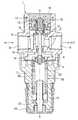
図1,図2及び図4(a) は、本発明の圧力制御装置の実施の形態第1を示す。なお、図2は図1のX−X断面を示す図であるが、ボンネット7の内部は図1と同様であるので、ボンネット7の一部は省略されている。圧力制御装置本体1内に主弁2とダイヤフラム4とが配設されるとともに圧力制御装置本体1の外部に方向制御弁5が配設されている。圧力制御装置本体1はボディ6とボンネット7により構成され、ボディ6とボンネット7との間にダイヤフラム4の外周部が挟持されている。ボディ6の2つの側面に開口された供給ポート8及び出力ポート9が形成され、供給ポート8と出力ポート9とを連通させる通路に主弁2が配置されている。主弁2には主弁体と主弁座があり、主弁2はバルブスプリング10によって閉じる方向に付勢されている。すなわち、ボディ6の上面に開口された中央孔12が形成され、中央孔12は供給ポート8に連通され、中央孔12の下方に主弁座が配置されている。中央孔12にはバルブガイドアセンブリ13が配設され、バルブガイドアセンブリ13の上側にカバー14及びキャップ15が配設されている。バルブガイドアセンブリ13にはバルブ受けが形成され、バルブ受けと主弁2の主弁体との間にバルブスプリング10が装着され、バルブスプリング10によって主弁体が主弁座に接触する方向に付勢されている。
【0008】
ダイヤフラム4によってダイヤフラム室16が形成され、言い換えればダイヤフラム4とボディ隔壁17との間にダイヤフラム室16が形成されている。ボディ隔壁17の中央部に挿通孔が形成され、挿通孔の周りのボディ隔壁17と主弁2の主弁座との間に中央連通路18が形成され、中央連通路18は出力ポート9に連通されている。主弁2の主弁体の中央部にステム19の基端が連結され、ステム19の下方部はボディ隔壁17の挿通孔に摺動自在で気密状態に挿入されている。ダイヤフラム4の中央部にシェル3が固定され(図1〜図4には、符号3として排出弁が示されているが、実際にはダイヤフラム4の上面に円板があり、ダイヤフラム4の下側にスプリング受けがあるものとする。)、ステム19の先端がシェル3に当接可能な状態に配置されている。バルブスプリング10はステム19を介してシェル3を押し下げる方向に付勢している。
【0009】
ボンネット7内でダイヤフラム4の下側に調圧スプリング室20が形成され、調圧スプリング室20の下方位置にナット21が回転不能かつ往復動自在な状態に挿入されている。シェル3のスプリング受けとナット21との間に調圧スプリング22が装着され、調圧スプリング22はステム19を介して主弁2を開く方向に付勢している。ナット21の雌ねじには調圧スクリュー23が螺合され、調圧スクリュー23の下端はハンドル24に結合されている。ハンドル24・調圧スクリュー23を回転させると、ナット21が上方向又は下方向に移動し、調圧スプリング22の付勢力を調節することができる。ボンネット7の側壁には排出ポート25が形成され、排出ポート25によって調圧スプリング室20が大気に連通されている。
【0010】
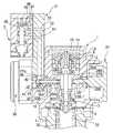
図2に示されているように、圧力制御装置本体1のボディ6の2つの側面(上面視で供給ポート8と出力ポート9とは90度ずれた位置)にアダプタ接続口26A、26Bが形成されている。アダプタ接続口26A、26Bは多段径の孔であって、外側から順に大径孔27A、27B、中径孔28A、28B、小径孔29A、29Bが隣接して形成されている。そして、小径孔29A、29Bは圧力連通路30A、30Bによって中央連通路18にそれぞれ連通され、中径孔28A、28Bは圧力連通路33A、33Bによってそれぞれダイヤフラム室16に連通されている。アダプタ接続口26Aの大径孔27Aにアダプタ31の接続用突出部34が気密状態に嵌合して接続され、アダプタ接続口26Bの大径孔27B、中径孔28B、小径孔29Bにブランキングプレートアセンブリ35の密封用突出部36が気密状態に装着され、アダプタ接続口26Bが密封されている。なお、アダプタ接続口26Bの大径孔27Bにアダプタ31の接続用突出部34が気密状態に嵌合して接続され、アダプタ接続口26Aの大径孔27A、中径孔28A、小径孔29Aにブランキングプレートアセンブリ35の密封用突出部36が気密状態に装着され、アダプタ接続口26Aが密封されるようにしてもよい。
【0011】
アダプタ31の外側には方向制御弁5及び圧力計38が取り付けられ、圧力計38の取付用突出部39はシールを介してアダプタ31の取付孔40に嵌合されている。アダプタ31には圧力計38及び方向制御弁5に二次側圧力(出力ポート9の圧力)を導くため等の多段連通孔41が形成され、多段連通孔41には内側から順に大径孔42、中径孔43、小径孔44が隣接して配設されている。アダプタ31の多段連通孔41とボディ6のアダプタ接続口26Aには連通パイプ45が装着され、連通パイプ45の左端はアダプタ31の中径孔43に密封状態に嵌合され、連通パイプ45の右端はボディ6の小径孔29Aに密封状態に嵌合されている。二次側圧力は、出力ポート9から中央連通路18、圧力連通路30A、連通パイプ45の内部通路、アダプタ31の小径孔44、取付用突出部39の内部通路を通って圧力計38に導かれる。
【0012】
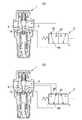
図2・図4(a) に示すように、方向制御弁5には小入力ポート46、47及び小出力ポート48がある。スプール49が図示のオフ位置Iにあるときは、小入力ポート47が閉じ、小入力ポート46と小出力ポート48とが連通され、スプール49を流体圧等(人力,機械,パイロット圧,電磁式の操作方法を含む。以下、同じ。)によりスプリングの付勢力に抗してオン位置IIに切り換えると、小入力ポート46が閉じ、小入力ポート47と小出力ポート48とが連通される。アダプタ31には入力連通路50、51及び出力連通路52が形成され、第1入力連通路(入力連通路50)は小入力ポート46と大気とを連通し、入力連通路51は小入力ポート47と小径孔44とを連通し、出力連通路52は小出力ポート48と大径孔42とを連通している。従って、方向制御弁5の小入力ポート47は、アダプタ31の第2A入力連通路(入力連通路51、小径孔44)、連通パイプ45の内部通路、及びボディ6の第2B入力連通路(圧力連通路30A、中央連通路18)を通して出力ポート9に連通されている。方向制御弁5の小出力ポート48は、アダプタ31の第1A出力連通路(出力連通路52、大径孔42)及びボディ6の第1B出力連通路(大径孔27A、中径孔28A、圧力連通路33A)を通してダイヤフラム室16に連通されている。
【0013】
次に、実施の形態第1の動作について説明する。方向制御弁5がオフ位置Iにあるとき、ダイヤフラム室16はボディ6の第1B出力連通路、アダプタ31の第1A出力連通路、方向制御弁5の小出力ポート48、小入力ポート46及び第1入力連通路を通して大気に連通されており、ダイヤフラム室16内は大気圧となっている。そして、調圧スプリング22の付勢力はバルブスプリング10の付勢力よりもはるかに大きい。従って、バルブスプリング10の付勢力に抗して、調圧スプリング22の付勢力によりダイヤフラム4、シェル3、ステム19、主弁2の弁体が上方へ移動され、主弁2は全開状態になっている。圧力流体を供給ポート8に供給すると、圧力流体は全開の主弁2、中央連通路18、出力ポート9を通って不図示の流体シリンダに流れる。主弁2が全開状態であるので、出力ポート9の二次側圧力は供給ポート8の一次側圧力に等しい。
【0014】
方向制御弁5のスプール49をオン位置IIに切り換えると、小入力ポート46が閉じ、小入力ポート47が小出力ポート48に連通する。二次側圧力は、出力ポート9からボディ6の第2B入力連通路、連通パイプ45の内部通路、アダプタ31の第2A入力連通路、方向制御弁5の小入力ポート47に流れ、更に方向制御弁5の小出力ポート48、アダプタ31の第1A出力連通路、ボディ6の第1B出力連通路を通してダイヤフラム室16に連通される。従って、ダイヤフラム室16の内部が二次側圧力となり、二次側圧力が大面積のダイヤフラム4の上面に作用して下向きの力を発生し、調圧スプリング22の付勢力と対抗する。主弁2で減圧された圧力流体が出力ポート9に流れ、二次側圧力が設定圧力になると、ダイヤフラム4が押し下げられて主弁2が閉じ、二次側圧力が設定圧力より低くなると、主弁2が開き供給ポート8の圧力流体が減圧されて出力ポート9に流れる。供給ポート8に供給された圧力流体は、主弁2によって設定圧に減圧され、設定圧に減圧された流体は、出力ポート9を通って不図示の流体シリンダに流れる。実施の形態第1の圧力制御装置は、カシメ機、自動ドア等に適用される。
【0015】
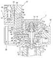
図1,図3及び図4(b) は本発明の圧力制御装置の実施の形態第2を示す。なお、図3は図1(実施の形態第2)のX−X断面を示す図であるが、ボンネット7の内部は図1と同様であるので、ボンネット7の一部は省略されている。実施の形態第2は、方向制御弁5の小入力ポート46、47、小出力ポート48の連通箇所が、実施の形態第1と異なるが、その他の点は実施の形態第1と同一である。図3及び図4(b) において、図2及び図4(a) と同一の部材には図2及び図4(a) と同一の符号を付し、その部分の説明は省略又は簡略にする。
【0016】
図3及び図4(b) において、アダプタ31には連通用突出部57が形成されるとともに、ボディ6には連通用凹部58が形成され、連通用突出部57は連通用凹部58に嵌合されている。連通用凹部58は入力連通路59を通して中央孔12に連通され、連通用突出部57には後述の出力連通路54の端部が形成され、入力連通路59と出力連通路54とが連通状態とされている。方向制御弁5には小入力ポート46、47及び小出力ポート48があり、スプール49が図示のオフ位置Iにあるときは、小入力ポート46が閉じ、小入力ポート47と小出力ポート48とが連通され、スプール49を流体圧等によりスプリングの付勢力に抗してオン位置IIに切り換えると、小入力ポート47が閉じ、小入力ポート46と小出力ポート48とが連通される。アダプタ31には入力連通路54、55及び出力連通路56が形成され、方向制御弁5の小入力ポート46はアダプタ31の第3A入力連通路(入力連通路54)及びボディ6の第3B入力連通路(入力連通路59、中央孔12)を通して供給ポート8に連通されている。方向制御弁5の小入力ポート47は、アダプタ31の入力連通路55を通して小径孔44に連通され、方向制御弁5の小出力ポート48は出力連通路56を通して大径孔42に連通されている。
【0017】
次に、実施の形態第2の圧力制御装置の作動について説明する。方向制御弁5がオフ位置Iにあるとき、ダイヤフラム室16は、ボディ6の第1B出力連通路(圧力連通路33A、中径孔28A、大径孔27A)、アダプタ31の第1A出力連通路(小径孔42、出力連通路56)、方向制御弁5の小出力ポート48、小入力ポート47、アダプタ31の第2A出力連通路(入力連通路55、小入力孔44)、連通パイプ45の内部通路、ボディ6の第2B出力連通路(圧力連通路30A、中央連通路18)を通して出力ポート9に連通されている。供給ポート8に圧力流体を供給すると、実施の形態第1の方向制御弁5をオン位置IIにしたときと同様に、二次側圧力が設定圧力に減圧される。
【0018】
方向制御弁5をオン位置IIに切り換えると、小入力ポート47が閉じ、小入力ポート46が小出力ポート48に連通される。供給ポート8の圧力流体は、ボディ6の第3B入力連通路、アダプタ31の第3A入力連通路、方向制御弁5の小入力ポート46、小出力ポート48、アダプタ31の第1A出力連通路、ボディ6の第1B出力連通路を通ってダイヤフラム室16に流れる。ダイヤフラム室16に流入した一次側圧力によってダイヤフラム4が下降し、バルブスプリング10によって主弁2が全閉となる。実施の形態第2の圧力制御装置は、エアブロー、エアモータ等に適用される。
【0019】
実施の形態第1及び実施の形態第2においては、2位置3ポートの方向制御弁をそれぞれ1個用いており、実施の形態第1ではダイヤフラム室16を二次側圧力又は大気圧となし、実施の形態第2ではダイヤフラム室16を二次側圧力又は一次側圧力としている。しかし、2位置3ポートの方向制御弁を2個直列に接続し、ダイヤフラム室16を二次側圧力、大気圧又は一次側圧力のいずれか一つになすことができる。
【0020】
【発明の効果】
請求項1の圧力制御装置によれば、方向制御弁の切換操作によって主弁を制御することにより、出力ポートの圧力を制御する圧力制御装置において、ダイヤフラム室が出力ポートの圧力となったときには、主弁によって供給ポートの流体が設定圧力に減圧されて出力ポートに流れ、ダイヤフラム室が大気圧となったときには、主弁が全開となって供給ポートの流体が出力ポートに流れて、出力ポートの圧力が一次側圧力になり、カシメ機、自動ドア等に適用できる。従来例の高圧設定装置、圧力設定室等が不要であるので、構造が簡略となりコストが低減する。
請求項2の圧力制御装置においては、方向制御弁の切換操作によって主弁を制御することにより、出力ポートの圧力を制御する圧力制御装置において、ダイヤフラム室が出力ポートの圧力となったときには、主弁によって供給ポートの流体が設定圧力に減圧されて出力ポートに流れ、ダイヤフラム室が供給ポートの圧力となったときには、主弁が全閉となって供給ポートと出力ポートとの間の通路が遮断され、エアブロー、エアモータ等に適用できる。
また、従来例の高圧設定装置、圧力設定室等が不要であるので、構造が簡略となりコストが低減する。
請求項4の圧力制御装置によれば、2つのアダプタ接続口のいずれかにアダプタが接続され、残りのアダプタ接続口をブランキングプレートアセンブリによって閉鎖する。アダプタを2つのアダプタ接続口の任意の方に接続できるので、装置の組み立ての自由度が増加する。
【図面の簡単な説明】
【図1】本発明の圧力制御装置の実施の形態第1及び第2の側断面図である。
【図2】実施の形態第1の図1のX−X線断面図である。
【図3】実施の形態第2の図1のX−X線断面図である。
【図4】図4(a) は実施の形態第1の方向制御弁を記号で示した説明図であり、図4(b) は実施の形態第2の方向制御弁を記号で示した説明図である。
【図5】従来の圧力制御装置の側断面図である。
【符号の説明】
1 圧力制御装置本体
5 方向制御弁
8 供給ポート
9 出力ポート
16 ダイヤフラム室
46 小入力ポート
47 小入力ポート
48 小出力ポート[0001]
BACKGROUND OF THE INVENTION
The present invention relates to a pressure control device that controls a main valve by switching a directional control valve to control the pressure of an output port.
[0002]
[Prior art]
FIG. 5 shows a pressure control device that controls the pressure of the output port to two pressures, high and low, by controlling the main valve and the discharge valve by switching the direction control valve (actual fairness 1-72612). Issue gazette). In FIG. 5, the pressure fluid is supplied to the supply port P in a state where the
[0003]
Next, when the
[0004]
In the prior art of FIG. 5, a pressure fluid having a first set pressure and a second set pressure is obtained, and each set pressure is controlled to a constant pressure by feedback control. However, depending on the application of the fluid pressure cylinder, feedback control may not be necessary. As a first example, out of the full stroke L of the piston of the fluid pressure cylinder, stroke L1 fully opens the main valve and moves the piston at high speed to shorten the stroke time, and the remaining stroke L2 is pushed at the set pressure. The stroke L1 can be operated at a low set pressure to ensure safety, and the remaining stroke L2 can be operated at a high pressure with the main valve fully open (eg automatic door). is there. As a second example, there is a case in which a fluid having a set pressure is sent for a desired time, and then the fluid flow is stopped (for example, an air blow or a fluid pressure motor). When applied to the first example and the second example, the conventional example of FIG. 5 has unnecessary functions more than necessary and is useless.
[0005]
[Problems to be solved by the invention]
The present invention is intended to eliminate the above waste, and in the pressure control device for controlling the pressure of the output port by controlling the main valve by the switching operation of the direction control valve, the main valve is fully closed, A first problem is to have anytwo functions of decompression and full open, and a second problem is to reduce the cost by simplifying the configuration.
[0006]
[Means for Solving the Problems]
In order to achieve the above object, according to the present invention, a main valve and a diaphragm are disposed in the pressure control device main body, and a directional control valve is disposed outside the pressure control device main body. The diaphragm chamber is formed by the diaphragm, and is urged in the direction in which the main valve is closed by the valve spring, and is urged in the direction in which the main valve is opened by the pressure adjusting spring acting on the diaphragm, In a pressure control device in which the force acting on the diaphragm changes due to the switching operation of the direction control valve, and the pressure of the output port changes, anadapter is disposed on the side of thepressure control device body, and the direction control valve is located outside the adapter. Connected, two small input ports and one small output port are formed in the directional control valve, and the multistage communication hole of the adapter and the pressure control device main body A communication pipe is mounted between the adapter connection port of the diameter, and the small output port of the directional control valve is located between the adapter multi-stage communication hole and the adapter control port of the pressure control device main body and the outside of the communication pipe. One small input port of the directional control valve communicates with the atmosphere through a passage formed in the adapter, and the other small input port of the directional control valve communicates with the passage in the communication pipe. It communicates with the output port via,become pressure or atmospheric pressure of the diaphragm chamber by switching operation ofrectangular direction control valveoutput port, when the diaphragm chamber becomes the pressureof the output port,fluid is setin the supply port by the main valve flows to the output port is depressurized to a pressure, when the diaphragm chamber becomes atmospheric pressure,the fluid supply port main valve is fully opento flow to the output port It is an butterfly.
Further, according to the present invention, a main valve and a diaphragm are disposed in the pressure control device main body, and a directional control valve is disposed outside the pressure control device main body, and the main valve communicates the supply port and the output port. A diaphragm chamber is formed by the diaphragm, which is arranged in the passage, and is biased in the direction in which the main valve is closed by the valve spring, and is biased in the direction in which the main valve is opened by the pressure regulating spring acting on the diaphragm, and the switching operation of the direction control valve In the pressure control device in which the force acting on the diaphragm is changed by the pressure and the pressure of the output port changes, an adapter is disposed on the side of the pressure control device main body, a direction control valve is connected to the outside of the adapter, and the direction control valve Two small input ports and one small output port are formed in the adapter, and the multistage communication hole of the adapter and the adapter connection port of the multistage diameter of the pressure control device body A small output port of the directional control valve is connected to the diaphragm chamber through a passage between the multistage communication hole of the adapter and the adapter connection port of the main body of the pressure control device and the outside of the communication pipe. One small input port of the directional control valve is communicated with the supply port via a passage formed in the adapter and the pressure control device main body, and the other small input port of the directional control valve is connected to the communication pipe. When the diaphragm chamber becomes the pressure of the output port or the pressure of the supply port by the switching operation of the directional control valve, and the diaphragm chamber becomes the pressure of the output port, the supply port is When the fluid is reduced to the set pressure and flows to the output port, and the diaphragm chamber reaches the supply port pressure, the main valve is fully closed and the supply port It is characterized in that between the output port is blocked.
In a preferred embodiment of the present invention, one end of the communication pipe is hermetically fitted to the medium diameter hole of the multistage communication hole of the adapter, and the other end of the communication pipe is a small diameter of the adapter connection port of the main body of the pressure control device. The small output port of the direction control valve is connected to the large diameter hole of the multi-stage communication hole of the adapter, and the medium diameter hole of the adapter connection port of the pressure control device is connected to the diaphragm chamber. The other small input port of the control valve is configured to communicate with the small diameter hole of the multistage communication hole of the adapter.
Further, according to the present invention, a main valve and a diaphragm are disposed in the pressure control device main body, and a directional control valve is disposed outside the pressure control device main body, and the main valve communicates the supply port and the output port. A diaphragm chamber is formed by the diaphragm, which is arranged in the passage, and is biased in the direction in which the main valve is closed by the valve spring, and is biased in the direction in which the main valve is opened by the pressure regulating spring acting on the diaphragm, and the switching operation of the direction control valve In the pressure control device in which the force acting on the diaphragm is changed by the pressure and the pressure of the output port changes, a central communication passage is formed in the passage connecting the main valve and the output port, and adapters are respectively attached to the two side surfaces of the pressure control device main body. A connection port is formed, and each adapter connection port is communicated with the central communication channel by a pressure communication channel. Descriptor is connected, a pressure gauge is arranged in the adapter,the pressure of the output port is central communication passage, is transmitted to the pressure gauge through the pressure communicating passage, the other adapter connection port is closed by a blanking plate assemblyIt is characterized by.
[0007]
DETAILED DESCRIPTION OF THE INVENTION
1, 2 and 4 (a) show a first embodiment of the pressure control device of the present invention. 2 is a cross-sectional view taken along the line XX of FIG. 1. However, since the inside of the
[0008]
[0009]
A pressure regulating
[0010]
As shown in FIG. 2, adapter connection ports 26 </ b> A and 26 </ b> B are formed on two side surfaces of the
[0011]
The
[0012]
As shown in FIGS. 2 and 4A, the
[0013]
Next, the first operation of the embodiment will be described. When the
[0014]
When the
[0015]
1, 3 and 4 (b) show a second embodiment of the pressure control device of the present invention. 3 is a cross-sectional view taken along the line XX of FIG. 1 (second embodiment). However, since the inside of the
[0016]
3 and 4 (b), the
[0017]
Next, the operation of the second pressure control apparatus according to the embodiment will be described. When the
[0018]
When the
[0019]
In the first and second embodiments, one two-position, three-port directional control valve is used. In the first embodiment, the
[0020]
【The invention's effect】
According tothe pressure control deviceof
In the pressure control device according to
Further, since the conventional high pressure setting device, pressure setting chamber and the like are unnecessary, the structure is simplified and the cost is reduced.
According to the pressure control device of thefourth aspect, the adapter is connected to one of the two adapter connection ports, and the remaining adapter connection ports are closed by the blanking plate assembly. Since the adapter can be connected to any one of the two adapter connection ports, the degree of freedom in assembling the apparatus is increased.
[Brief description of the drawings]
FIG. 1 is a first and second side cross-sectional view of a pressure control apparatus according to an embodiment of the present invention.
FIG. 2 is a cross-sectional view taken along line XX of FIG. 1 of the first embodiment.
3 is a sectional view taken along line XX of FIG. 1 of the second embodiment.
FIG. 4 (a) is an explanatory diagram showing the first directional control valve of the embodiment with a symbol, and FIG. 4 (b) is an explanation showing the second directional control valve of the embodiment with a symbol. FIG.
FIG. 5 is a side sectional view of a conventional pressure control device.
[Explanation of symbols]
1 Pressure
16 Diaphragm room
46 Small input port
47 Small input port
48 Small output port
Claims (4)
Translated fromJapanese圧力制御装置本体の側部にアダプタが配設され、アダプタの外側に方向制御弁が連結され、方向制御弁に2つの小入力ポート及び1つの小出力ポートが形成され、アダプタの多段連通孔と圧力制御装置本体の多段径のアダプタ接続口との間に連通パイプが装着され、方向制御弁の小出力ポートは、アダプタの多段連通孔及び圧力制御装置本体のアダプタ接続口の内側と上記連通パイプの外側との間の通路を介してダイヤフラム室に連通され、方向制御弁の一方の小入力ポートはアダプタに形成された通路によって大気に連通され、方向制御弁の他方の小入力ポートは、上記連通パイプ内の通路を介して出力ポートに連通され、
方向制御弁の切換操作によってダイヤフラム室が出力ポートの圧力又は大気圧になり、ダイヤフラム室が出力ポートの圧力となったときには、主弁によって供給ポートの流体が設定圧力に減圧されて出力ポートに流れ、ダイヤフラム室が大気圧となったときには、主弁が全開して供給ポートの流体が出力ポートに流れる、
ことを特徴とする圧力制御装置。A main valve and a diaphragm are disposed in the main body of the pressure control device, and a directional control valve is disposed outside the main body of the pressure control device. The main valve is disposed in a passage communicating the supply port and the output port. The diaphragm chamber is formed by the valve spring, and the main valve is urged by the valve spring in the closing direction. In the pressure control device where the output port pressure changes as the
An adapter is disposed on the side of the pressure control device main body, a directional control valve is connected to the outside of the adapter, two small input ports and one small output port are formed in the directional control valve, and a multistage communication hole of the adapter is formed. A communication pipe is mounted between the multi-diameter adapter connection port of the pressure control device main body, and the small output port of the directional control valve includes the multi-stage communication hole of the adapter and the inside of the adapter connection port of the pressure control device main body and the communication pipe. Is communicated with the diaphragm chamber through a passage between the outside of the directional control valve, one small input port of the directional control valve is communicated with the atmosphere by a passage formed in the adapter, and the other small input port of the directional control valve is It communicates with the output port through the passage in the communication pipe,
Squarebecomes pressure or atmospheric pressure of the diaphragm chamberoutput port by switching operation direction control valve, when the diaphragm chamber becomes the pressureof the output port, the pressure is reduced in the output port to thefluid set pressureof the supply port by the main valve When the diaphragm chamber is at atmospheric pressure, the main valve is fully opened andthe fluid in thesupply port flows to the output port.
A pressure control device characterized by that.
圧力制御装置本体の側部にアダプタが配設され、アダプタの外側に方向制御弁が連結され、方向制御弁に2つの小入力ポート及び1つの小出力ポートが形成され、アダプタの多段連通孔と圧力制御装置本体の多段径のアダプタ接続口との間に連通パイプが装着され、方向制御弁の小出力ポートは、アダプタの多段連通孔及び圧力制御装置本体のアダプタ接続口の内側と上記連通パイプの外側との間の通路を介してダイヤフラム室に連通され、方向制御弁の一方の小入力ポートは、アダプタ及び圧力制御装置本体に形成された通路を介して供給ポートに連通され、方向制御弁の他方の小入力ポートは、上記連通パイプ内の通路を介して出力ポートに連通され、 An adapter is disposed on the side of the pressure control device main body, a directional control valve is connected to the outside of the adapter, two small input ports and one small output port are formed in the directional control valve, and a multistage communication hole of the adapter is formed. A communication pipe is mounted between the multi-diameter adapter connection port of the pressure control device main body, and the small output port of the directional control valve includes the multi-stage communication hole of the adapter and the inside of the adapter connection port of the pressure control device main body and the communication pipe. One small input port of the direction control valve communicates with the supply port via a passage formed in the adapter and the pressure control device body, and communicates with the diaphragm chamber via a passage between the outside and the direction control valve. The other small input port is communicated with the output port via a passage in the communication pipe,
方向制御弁の切換操作によってダイヤフラム室が出力ポートの圧力又は供給ポートの圧力になり、ダイヤフラム室が出力ポートの圧力となったときには、主弁によって供給ポートの流体が設定圧力に減圧されて出力ポートに流れ、ダイヤフラム室が供給ポートの圧力となったときには、主弁が全閉となって供給ポートと出力ポートとの間が遮断される、 When the direction of the directional control valve is switched, the diaphragm chamber becomes the pressure of the output port or the pressure of the supply port, and when the diaphragm chamber becomes the pressure of the output port, the fluid in the supply port is reduced to the set pressure by the main valve, and the output port When the diaphragm chamber reaches the pressure of the supply port, the main valve is fully closed and the supply port and the output port are blocked.
ことを特徴とする圧力制御装置。A pressure control device characterized by that.
ことを特徴とする請求項1又は2記載の圧力制御装置。The pressure control apparatus according to claim 1 or 2, wherein
主弁と出力ポートを連通する通路に中央連通路が形成され、圧力制御装置本体の2つの側面にそれぞれアダプタ接続口が形成され、各アダプタ接続口がそれぞれ圧力連通路によって中央連通路に連通され、一方のアダプタ接続口にアダプタが接続され、アダプタに圧力計が配設され、出力ポートの圧力が中央連通路、圧力連通路を介して圧力計に伝達され、他方のアダプタ接続口がブランキングプレートアセンブリによって閉鎖された圧力制御装置。A main valve and a diaphragm are disposed in the main body of the pressure control device, and a directional control valve is disposed outside the main body of the pressure control device. The main valve is disposed in a passage communicating the supply port and the output port. The diaphragm chamber is formed by the valve spring, and the main valve is urged by the valve spring in the closing direction. In the pressure control device where the output port pressure changes as the
A central communication passage is formed in the passage connecting the main valve and the output port, adapter connection ports are respectively formed on the two side surfaces of the pressure control device main body, and each adapter connection port is connected to the central communication passage by the pressure communication passage. An adapter is connected to one adapter connection port, a pressure gauge is installed on the adapter, the pressure of the output port is transmitted to the pressure gauge via the central communication path and pressure communication path, and the other adapter connection port is blanked Pressure control device closed by a plate assembly.
Priority Applications (2)
| Application Number | Priority Date | Filing Date | Title |
|---|---|---|---|
| JP2002187538AJP4035711B2 (en) | 2002-06-27 | 2002-06-27 | Pressure control device |
| US10/465,709US7007713B2 (en) | 2002-06-27 | 2003-06-19 | Pressure control apparatus |
Applications Claiming Priority (1)
| Application Number | Priority Date | Filing Date | Title |
|---|---|---|---|
| JP2002187538AJP4035711B2 (en) | 2002-06-27 | 2002-06-27 | Pressure control device |
Publications (2)
| Publication Number | Publication Date |
|---|---|
| JP2004028248A JP2004028248A (en) | 2004-01-29 |
| JP4035711B2true JP4035711B2 (en) | 2008-01-23 |
Family
ID=29774191
Family Applications (1)
| Application Number | Title | Priority Date | Filing Date |
|---|---|---|---|
| JP2002187538AExpired - LifetimeJP4035711B2 (en) | 2002-06-27 | 2002-06-27 | Pressure control device |
Country Status (2)
| Country | Link |
|---|---|
| US (1) | US7007713B2 (en) |
| JP (1) | JP4035711B2 (en) |
Families Citing this family (4)
| Publication number | Priority date | Publication date | Assignee | Title |
|---|---|---|---|---|
| US9396212B2 (en)* | 2004-04-07 | 2016-07-19 | Visible World, Inc. | System and method for enhanced video selection |
| DE102004046547A1 (en)* | 2004-09-20 | 2006-04-06 | Festo Ag & Co. | Fluid technical device with pressure regulator |
| KR101310083B1 (en)* | 2013-04-22 | 2013-09-23 | (주)대신테크 | Reciprocating air moter |
| JP7039985B2 (en)* | 2017-12-15 | 2022-03-23 | ヤマハ株式会社 | Mixer, mixer control method and program |
Family Cites Families (7)
| Publication number | Priority date | Publication date | Assignee | Title |
|---|---|---|---|---|
| US625325A (en)* | 1899-05-23 | The norris peters co | ||
| US763375A (en)* | 1901-10-25 | 1904-06-28 | Pneumatic Signal Company | Fluid-pressure-reducing valve. |
| US1764790A (en)* | 1928-06-28 | 1930-06-17 | Hook Charles Howard | Pressure-regulating and shut-off valve |
| US1874293A (en)* | 1930-02-03 | 1932-08-30 | Hook Charles Howard | Combination pressure regulating and shut-off valve |
| SE451153B (en)* | 1986-01-20 | 1987-09-07 | Dominator Ab | SET TO CHANGE PRESSURE IN PNEUMATIC OR HYDRAULIC SYSTEM AND DEVICE TO PERFORM THE SET |
| JPS6472612A (en) | 1987-09-12 | 1989-03-17 | Tokin Corp | Noise filter |
| US5427350A (en)* | 1994-05-31 | 1995-06-27 | Rinkewich; Isaac | Electrically-operated control valve and water distribution system including same |
- 2002
- 2002-06-27JPJP2002187538Apatent/JP4035711B2/ennot_activeExpired - Lifetime
- 2003
- 2003-06-19USUS10/465,709patent/US7007713B2/ennot_activeExpired - Lifetime
Also Published As
| Publication number | Publication date |
|---|---|
| JP2004028248A (en) | 2004-01-29 |
| US7007713B2 (en) | 2006-03-07 |
| US20040000340A1 (en) | 2004-01-01 |
Similar Documents
| Publication | Publication Date | Title |
|---|---|---|
| US7090190B2 (en) | Flow control valve | |
| US6991211B2 (en) | Pneumatically actuated valve | |
| US20020007727A1 (en) | Pneumatic volume booster for valve positioner | |
| EP0869418B1 (en) | Pressure regulating valve mounted in base-mounted transfer valve | |
| JP5741979B2 (en) | Two stage air control valve | |
| US20010045537A1 (en) | Booster pilot valve | |
| JP2014512496A (en) | Poppet valve assembly for controlling pneumatic actuators | |
| CA2485018A1 (en) | Fluid control valve | |
| JP4426136B2 (en) | Flow control valve | |
| JP4035711B2 (en) | Pressure control device | |
| US6062260A (en) | Dual piston pilot valve | |
| JP4108596B2 (en) | Compound automatic valve with manual operation mechanism | |
| US6405755B1 (en) | Directly controlled magnetic valve | |
| JP2006528330A (en) | Servo valve of vacuum system | |
| JPH11236904A (en) | Aerodynamic-force type control valve | |
| KR100438637B1 (en) | Spacer type pressure reducing valve | |
| KR100812560B1 (en) | Flow control valve | |
| KR101815517B1 (en) | 3-Way Valve having a Internal Pressure Contolling Appartus | |
| JPS6123985Y2 (en) | ||
| KR102512707B1 (en) | Two way solenoid valve | |
| US20230417341A1 (en) | Valve system | |
| JP2002364770A (en) | Fluid control valve | |
| JPH10141524A (en) | Pilot three-way solenoid valve | |
| KR200212125Y1 (en) | Pilot Solenoid Valve | |
| JP2673923B2 (en) | solenoid valve |
Legal Events
| Date | Code | Title | Description |
|---|---|---|---|
| A621 | Written request for application examination | Free format text:JAPANESE INTERMEDIATE CODE: A621 Effective date:20050325 | |
| A131 | Notification of reasons for refusal | Free format text:JAPANESE INTERMEDIATE CODE: A131 Effective date:20070522 | |
| A977 | Report on retrieval | Free format text:JAPANESE INTERMEDIATE CODE: A971007 Effective date:20070524 | |
| A521 | Request for written amendment filed | Free format text:JAPANESE INTERMEDIATE CODE: A523 Effective date:20070723 | |
| RD03 | Notification of appointment of power of attorney | Free format text:JAPANESE INTERMEDIATE CODE: A7423 Effective date:20070723 | |
| TRDD | Decision of grant or rejection written | ||
| A01 | Written decision to grant a patent or to grant a registration (utility model) | Free format text:JAPANESE INTERMEDIATE CODE: A01 Effective date:20071002 | |
| A61 | First payment of annual fees (during grant procedure) | Free format text:JAPANESE INTERMEDIATE CODE: A61 Effective date:20071016 | |
| R150 | Certificate of patent or registration of utility model | Free format text:JAPANESE INTERMEDIATE CODE: R150 Ref document number:4035711 Country of ref document:JP Free format text:JAPANESE INTERMEDIATE CODE: R150 | |
| FPAY | Renewal fee payment (event date is renewal date of database) | Free format text:PAYMENT UNTIL: 20101109 Year of fee payment:3 | |
| FPAY | Renewal fee payment (event date is renewal date of database) | Free format text:PAYMENT UNTIL: 20111109 Year of fee payment:4 | |
| R250 | Receipt of annual fees | Free format text:JAPANESE INTERMEDIATE CODE: R250 | |
| FPAY | Renewal fee payment (event date is renewal date of database) | Free format text:PAYMENT UNTIL: 20121109 Year of fee payment:5 | |
| R250 | Receipt of annual fees | Free format text:JAPANESE INTERMEDIATE CODE: R250 | |
| FPAY | Renewal fee payment (event date is renewal date of database) | Free format text:PAYMENT UNTIL: 20131109 Year of fee payment:6 | |
| R250 | Receipt of annual fees | Free format text:JAPANESE INTERMEDIATE CODE: R250 | |
| R250 | Receipt of annual fees | Free format text:JAPANESE INTERMEDIATE CODE: R250 | |
| R250 | Receipt of annual fees | Free format text:JAPANESE INTERMEDIATE CODE: R250 | |
| R250 | Receipt of annual fees | Free format text:JAPANESE INTERMEDIATE CODE: R250 | |
| R250 | Receipt of annual fees | Free format text:JAPANESE INTERMEDIATE CODE: R250 | |
| R250 | Receipt of annual fees | Free format text:JAPANESE INTERMEDIATE CODE: R250 | |
| R250 | Receipt of annual fees | Free format text:JAPANESE INTERMEDIATE CODE: R250 | |
| R250 | Receipt of annual fees | Free format text:JAPANESE INTERMEDIATE CODE: R250 | |
| R250 | Receipt of annual fees | Free format text:JAPANESE INTERMEDIATE CODE: R250 | |
| R250 | Receipt of annual fees | Free format text:JAPANESE INTERMEDIATE CODE: R250 | |
| EXPY | Cancellation because of completion of term |