JP4032682B2 - Phosphor - Google Patents
PhosphorDownload PDFInfo
- Publication number
- JP4032682B2 JP4032682B2JP2001257420AJP2001257420AJP4032682B2JP 4032682 B2JP4032682 B2JP 4032682B2JP 2001257420 AJP2001257420 AJP 2001257420AJP 2001257420 AJP2001257420 AJP 2001257420AJP 4032682 B2JP4032682 B2JP 4032682B2
- Authority
- JP
- Japan
- Prior art keywords
- phosphor
- compound
- light
- matrix
- center ion
- Prior art date
- Legal status (The legal status is an assumption and is not a legal conclusion. Google has not performed a legal analysis and makes no representation as to the accuracy of the status listed.)
- Expired - Fee Related
Links
Images

Classifications
- C—CHEMISTRY; METALLURGY
- C09—DYES; PAINTS; POLISHES; NATURAL RESINS; ADHESIVES; COMPOSITIONS NOT OTHERWISE PROVIDED FOR; APPLICATIONS OF MATERIALS NOT OTHERWISE PROVIDED FOR
- C09K—MATERIALS FOR MISCELLANEOUS APPLICATIONS, NOT PROVIDED FOR ELSEWHERE
- C09K11/00—Luminescent, e.g. electroluminescent, chemiluminescent materials
- C09K11/08—Luminescent, e.g. electroluminescent, chemiluminescent materials containing inorganic luminescent materials
- C09K11/77—Luminescent, e.g. electroluminescent, chemiluminescent materials containing inorganic luminescent materials containing rare earth metals
- C09K11/7728—Luminescent, e.g. electroluminescent, chemiluminescent materials containing inorganic luminescent materials containing rare earth metals containing europium
- C09K11/7729—Chalcogenides
- C09K11/7731—Chalcogenides with alkaline earth metals
- C—CHEMISTRY; METALLURGY
- C09—DYES; PAINTS; POLISHES; NATURAL RESINS; ADHESIVES; COMPOSITIONS NOT OTHERWISE PROVIDED FOR; APPLICATIONS OF MATERIALS NOT OTHERWISE PROVIDED FOR
- C09K—MATERIALS FOR MISCELLANEOUS APPLICATIONS, NOT PROVIDED FOR ELSEWHERE
- C09K11/00—Luminescent, e.g. electroluminescent, chemiluminescent materials
- C09K11/08—Luminescent, e.g. electroluminescent, chemiluminescent materials containing inorganic luminescent materials
- C09K11/0883—Arsenides; Nitrides; Phosphides
- C—CHEMISTRY; METALLURGY
- C09—DYES; PAINTS; POLISHES; NATURAL RESINS; ADHESIVES; COMPOSITIONS NOT OTHERWISE PROVIDED FOR; APPLICATIONS OF MATERIALS NOT OTHERWISE PROVIDED FOR
- C09K—MATERIALS FOR MISCELLANEOUS APPLICATIONS, NOT PROVIDED FOR ELSEWHERE
- C09K11/00—Luminescent, e.g. electroluminescent, chemiluminescent materials
- C09K11/08—Luminescent, e.g. electroluminescent, chemiluminescent materials containing inorganic luminescent materials
- C09K11/66—Luminescent, e.g. electroluminescent, chemiluminescent materials containing inorganic luminescent materials containing germanium, tin or lead
- C09K11/664—Halogenides
- C09K11/665—Halogenides with alkali or alkaline earth metals
- C—CHEMISTRY; METALLURGY
- C09—DYES; PAINTS; POLISHES; NATURAL RESINS; ADHESIVES; COMPOSITIONS NOT OTHERWISE PROVIDED FOR; APPLICATIONS OF MATERIALS NOT OTHERWISE PROVIDED FOR
- C09K—MATERIALS FOR MISCELLANEOUS APPLICATIONS, NOT PROVIDED FOR ELSEWHERE
- C09K11/00—Luminescent, e.g. electroluminescent, chemiluminescent materials
- C09K11/08—Luminescent, e.g. electroluminescent, chemiluminescent materials containing inorganic luminescent materials
- C09K11/77—Luminescent, e.g. electroluminescent, chemiluminescent materials containing inorganic luminescent materials containing rare earth metals
- C09K11/7728—Luminescent, e.g. electroluminescent, chemiluminescent materials containing inorganic luminescent materials containing rare earth metals containing europium
- C—CHEMISTRY; METALLURGY
- C09—DYES; PAINTS; POLISHES; NATURAL RESINS; ADHESIVES; COMPOSITIONS NOT OTHERWISE PROVIDED FOR; APPLICATIONS OF MATERIALS NOT OTHERWISE PROVIDED FOR
- C09K—MATERIALS FOR MISCELLANEOUS APPLICATIONS, NOT PROVIDED FOR ELSEWHERE
- C09K11/00—Luminescent, e.g. electroluminescent, chemiluminescent materials
- C09K11/08—Luminescent, e.g. electroluminescent, chemiluminescent materials containing inorganic luminescent materials
- C09K11/77—Luminescent, e.g. electroluminescent, chemiluminescent materials containing inorganic luminescent materials containing rare earth metals
- C09K11/7766—Luminescent, e.g. electroluminescent, chemiluminescent materials containing inorganic luminescent materials containing rare earth metals containing two or more rare earth metals
- C09K11/77742—Silicates
- C—CHEMISTRY; METALLURGY
- C09—DYES; PAINTS; POLISHES; NATURAL RESINS; ADHESIVES; COMPOSITIONS NOT OTHERWISE PROVIDED FOR; APPLICATIONS OF MATERIALS NOT OTHERWISE PROVIDED FOR
- C09K—MATERIALS FOR MISCELLANEOUS APPLICATIONS, NOT PROVIDED FOR ELSEWHERE
- C09K11/00—Luminescent, e.g. electroluminescent, chemiluminescent materials
- C09K11/08—Luminescent, e.g. electroluminescent, chemiluminescent materials containing inorganic luminescent materials
- C09K11/77—Luminescent, e.g. electroluminescent, chemiluminescent materials containing inorganic luminescent materials containing rare earth metals
- C09K11/7783—Luminescent, e.g. electroluminescent, chemiluminescent materials containing inorganic luminescent materials containing rare earth metals containing two or more rare earth metals one of which being europium
- C09K11/7784—Chalcogenides
- C09K11/7787—Oxides
- C09K11/7789—Oxysulfides
- H—ELECTRICITY
- H01—ELECTRIC ELEMENTS
- H01L—SEMICONDUCTOR DEVICES NOT COVERED BY CLASS H10
- H01L2224/00—Indexing scheme for arrangements for connecting or disconnecting semiconductor or solid-state bodies and methods related thereto as covered by H01L24/00
- H01L2224/01—Means for bonding being attached to, or being formed on, the surface to be connected, e.g. chip-to-package, die-attach, "first-level" interconnects; Manufacturing methods related thereto
- H01L2224/42—Wire connectors; Manufacturing methods related thereto
- H01L2224/44—Structure, shape, material or disposition of the wire connectors prior to the connecting process
- H01L2224/45—Structure, shape, material or disposition of the wire connectors prior to the connecting process of an individual wire connector
- H01L2224/45001—Core members of the connector
- H01L2224/45099—Material
- H01L2224/451—Material with a principal constituent of the material being a metal or a metalloid, e.g. boron (B), silicon (Si), germanium (Ge), arsenic (As), antimony (Sb), tellurium (Te) and polonium (Po), and alloys thereof
- H01L2224/45138—Material with a principal constituent of the material being a metal or a metalloid, e.g. boron (B), silicon (Si), germanium (Ge), arsenic (As), antimony (Sb), tellurium (Te) and polonium (Po), and alloys thereof the principal constituent melting at a temperature of greater than or equal to 950°C and less than 1550°C
- H01L2224/45144—Gold (Au) as principal constituent
- H—ELECTRICITY
- H01—ELECTRIC ELEMENTS
- H01L—SEMICONDUCTOR DEVICES NOT COVERED BY CLASS H10
- H01L2224/00—Indexing scheme for arrangements for connecting or disconnecting semiconductor or solid-state bodies and methods related thereto as covered by H01L24/00
- H01L2224/01—Means for bonding being attached to, or being formed on, the surface to be connected, e.g. chip-to-package, die-attach, "first-level" interconnects; Manufacturing methods related thereto
- H01L2224/42—Wire connectors; Manufacturing methods related thereto
- H01L2224/47—Structure, shape, material or disposition of the wire connectors after the connecting process
- H01L2224/48—Structure, shape, material or disposition of the wire connectors after the connecting process of an individual wire connector
- H01L2224/4805—Shape
- H01L2224/4809—Loop shape
- H01L2224/48091—Arched
- H—ELECTRICITY
- H01—ELECTRIC ELEMENTS
- H01L—SEMICONDUCTOR DEVICES NOT COVERED BY CLASS H10
- H01L2224/00—Indexing scheme for arrangements for connecting or disconnecting semiconductor or solid-state bodies and methods related thereto as covered by H01L24/00
- H01L2224/01—Means for bonding being attached to, or being formed on, the surface to be connected, e.g. chip-to-package, die-attach, "first-level" interconnects; Manufacturing methods related thereto
- H01L2224/42—Wire connectors; Manufacturing methods related thereto
- H01L2224/47—Structure, shape, material or disposition of the wire connectors after the connecting process
- H01L2224/48—Structure, shape, material or disposition of the wire connectors after the connecting process of an individual wire connector
- H01L2224/481—Disposition
- H01L2224/48151—Connecting between a semiconductor or solid-state body and an item not being a semiconductor or solid-state body, e.g. chip-to-substrate, chip-to-passive
- H01L2224/48221—Connecting between a semiconductor or solid-state body and an item not being a semiconductor or solid-state body, e.g. chip-to-substrate, chip-to-passive the body and the item being stacked
- H01L2224/48245—Connecting between a semiconductor or solid-state body and an item not being a semiconductor or solid-state body, e.g. chip-to-substrate, chip-to-passive the body and the item being stacked the item being metallic
- H01L2224/48247—Connecting between a semiconductor or solid-state body and an item not being a semiconductor or solid-state body, e.g. chip-to-substrate, chip-to-passive the body and the item being stacked the item being metallic connecting the wire to a bond pad of the item
- H—ELECTRICITY
- H01—ELECTRIC ELEMENTS
- H01L—SEMICONDUCTOR DEVICES NOT COVERED BY CLASS H10
- H01L2224/00—Indexing scheme for arrangements for connecting or disconnecting semiconductor or solid-state bodies and methods related thereto as covered by H01L24/00
- H01L2224/01—Means for bonding being attached to, or being formed on, the surface to be connected, e.g. chip-to-package, die-attach, "first-level" interconnects; Manufacturing methods related thereto
- H01L2224/42—Wire connectors; Manufacturing methods related thereto
- H01L2224/47—Structure, shape, material or disposition of the wire connectors after the connecting process
- H01L2224/48—Structure, shape, material or disposition of the wire connectors after the connecting process of an individual wire connector
- H01L2224/481—Disposition
- H01L2224/48151—Connecting between a semiconductor or solid-state body and an item not being a semiconductor or solid-state body, e.g. chip-to-substrate, chip-to-passive
- H01L2224/48221—Connecting between a semiconductor or solid-state body and an item not being a semiconductor or solid-state body, e.g. chip-to-substrate, chip-to-passive the body and the item being stacked
- H01L2224/48245—Connecting between a semiconductor or solid-state body and an item not being a semiconductor or solid-state body, e.g. chip-to-substrate, chip-to-passive the body and the item being stacked the item being metallic
- H01L2224/48257—Connecting between a semiconductor or solid-state body and an item not being a semiconductor or solid-state body, e.g. chip-to-substrate, chip-to-passive the body and the item being stacked the item being metallic connecting the wire to a die pad of the item
- H—ELECTRICITY
- H01—ELECTRIC ELEMENTS
- H01L—SEMICONDUCTOR DEVICES NOT COVERED BY CLASS H10
- H01L2224/00—Indexing scheme for arrangements for connecting or disconnecting semiconductor or solid-state bodies and methods related thereto as covered by H01L24/00
- H01L2224/01—Means for bonding being attached to, or being formed on, the surface to be connected, e.g. chip-to-package, die-attach, "first-level" interconnects; Manufacturing methods related thereto
- H01L2224/42—Wire connectors; Manufacturing methods related thereto
- H01L2224/47—Structure, shape, material or disposition of the wire connectors after the connecting process
- H01L2224/49—Structure, shape, material or disposition of the wire connectors after the connecting process of a plurality of wire connectors
- H01L2224/491—Disposition
- H01L2224/49105—Connecting at different heights
- H01L2224/49107—Connecting at different heights on the semiconductor or solid-state body
- H—ELECTRICITY
- H01—ELECTRIC ELEMENTS
- H01L—SEMICONDUCTOR DEVICES NOT COVERED BY CLASS H10
- H01L2924/00—Indexing scheme for arrangements or methods for connecting or disconnecting semiconductor or solid-state bodies as covered by H01L24/00
- H01L2924/15—Details of package parts other than the semiconductor or other solid state devices to be connected
- H01L2924/181—Encapsulation
- H—ELECTRICITY
- H10—SEMICONDUCTOR DEVICES; ELECTRIC SOLID-STATE DEVICES NOT OTHERWISE PROVIDED FOR
- H10H—INORGANIC LIGHT-EMITTING SEMICONDUCTOR DEVICES HAVING POTENTIAL BARRIERS
- H10H20/00—Individual inorganic light-emitting semiconductor devices having potential barriers, e.g. light-emitting diodes [LED]
- H10H20/80—Constructional details
- H10H20/85—Packages
- H10H20/851—Wavelength conversion means
- H10H20/8511—Wavelength conversion means characterised by their material, e.g. binder
- H10H20/8512—Wavelength conversion materials
Landscapes
- Chemical & Material Sciences (AREA)
- Inorganic Chemistry (AREA)
- Engineering & Computer Science (AREA)
- Materials Engineering (AREA)
- Organic Chemistry (AREA)
- Luminescent Compositions (AREA)
- Led Device Packages (AREA)
Description
Translated fromJapanese【0001】
【発明の属する技術分野】
本発明は、母体化合物が発光中心イオンを含有する蛍光体、更に詳しくは、波長変換材料として、紫外光から可視光の範囲の光を吸収してより長波長の可視光を発し、発光ダイオード(LED)やレーザーダイオード(LD)等の半導体発光素子と組み合わせることにより演色性の高い発光素子を構成することができる蛍光体に関する。
【0002】
【従来の技術】
従来より、半導体発光素子としての窒化ガリウム(GaN)系青色発光ダイオードと、波長変換材料としての蛍光体とを組み合わせて構成される白色発光の発光素子が、消費電力が小さく長寿命であるという特徴を活かして画像表示装置や照明装置の発光源として注目されている。
【0003】
この発光素子は、そこで用いられる蛍光体が、GaN系青色発光ダイオードの発する青色領域の可視光を吸収して黄色光を発光することから、蛍光体に吸収されなかったダイオードの青色光との混色により白色の発光が得られるものであって、その蛍光体としては、代表的には、イットリウム・アルミニウム複合酸化物(Y3Al5O12)を母体とし、該母体内に発光中心イオンとしてのセリウム(Ce)を含有してなる蛍光体が知られているが、この蛍光体は、焼成温度が高い等、製造が必ずしも容易と言えるものではなかった。
【0004】
【発明が解決しようとする課題】
本発明は、前述の従来技術に鑑み、製造が容易な蛍光体を、更には、より演色性の高い発光素子を得ることができる蛍光体を開発すべくなされたものであって、従って、本発明は、製造が容易であると共に、演色性の高い発光色素を得ることができる蛍光体を提供することを目的とする。
【0005】
【課題を解決するための手段】
本発明者等は、前記課題を解決すべく鋭意検討した結果、2価、3価、及び4価の金属元素からなり、かつ2価金属元素としてCa、3価金属元素としてSc及び4価金属元素としてSiを必須金属元素とするガーネット結晶構造の化合物を母体とし、該母体内に発光中心イオンとして、セリウムを含有してなる蛍光体が、前記目的を達成できることを見出し本発明に到達したもので、従って本発明は、下記一般式(I)で表されるガーネット結晶構造の化合物を母体とし、該母体内に発光中心イオンとしてCeを含有してなる蛍光体を要旨とする。
【0006】
M1a M2b M3c Od (I)
[式(I)中、M1はCa、又はCa並びにMg及びZnからなる群から選ばれた2価の金属元素であり、M2はSc、又はSc並びにAl、Y及びLuからなる群から選ばれた3価の金属元素であり、M3はSi、又はSi並びにGe及びSnからなる群から選ばれた4価の金属元素である。aは2.7〜3.3、bは1.8〜2.2、cは2.7〜3.3、dは11.0〜13.0の範囲の数である。]
【0007】
【発明の実施の形態】
本発明の蛍光体は、前記一般式(I) で表されるガーネット結晶構造の化合物を母体とするものであり、一般に、M1、M2、及びM3の金属元素を含む複合酸化物であり、M13M22M33O12で表される公知のガーネット結晶構造の化合物の中で、本発明においては、そのM1が2価、M2が3価、M3が4価の金属元素である化合物を蛍光体の母体とすることを特徴とする。
【0008】
即ち、本発明は、蛍光体の母体として、例えば、前記Y3Al5O12等の複合酸化物が知られ、又、M1が2価、M2が3価、M3が4価の金属元素のガーネット結晶構造の化合物も前述の如く知られているものの、蛍光体としての特性はその母体を構成する元素及びその原子価等によって大きく変化するのに対して、このM1が2価、M2が3価、M3が4価の金属元素のガーネット結晶構造の化合物が蛍光体の母体として優れていることを見い出したことに依拠するものである。
【0009】
ここで、式(I) における2価の金属元素M1としては、発光効率等の面から、Mg、Ca、Zn、Sr、Cd、及びBaからなる群から選択された少なくとも1種であるのが好ましく、Mg、Ca、又はZnであるのが更に好ましく、Ca、又はCaとMgであるのが特に好ましい。
【0010】
又、式(I) における3価の金属元素M2としては、同様の面から、Al、Sc、Ga、Y、In、La、Gd、及びLuからなる群から選択された少なくとも1種であるのが好ましく、Al、Sc、Y、又はLuであるのが更に好ましく、Sc、又はScとY、又はScとLuであるのが特に好ましい。
【0011】
又、式(I) における4価の金属元素M3としては、同様の面から、Si、Ti、Ge、Zr、Sn、及びHfからなる群から選択された少なくとも1種であるのが好ましく、Si、Ge、又はSnである更に好ましく、Siであるのが特に好ましい。
【0012】
又、ガーネット結晶構造は、一般には、前述したように、式(I) におけるaが3、bが2、cが3で、dが12の体心立方格子の結晶であるが、本発明においては、後述する発光中心イオンの元素が、M1、M2、M3のいずれかの金属元素の結晶格子の位置に置換するか、或いは、結晶格子間の隙間に配置する等により、式(I) においてaが3、bが2、cが3で、dが12とはならない場合もあり得、従って、aは2.7〜3.3、bは1.8〜2.2、cは2.7〜3.3、dは11.0〜13.0の範囲の数をとることとなり、aは2.9〜3.1、bは1.95〜2.05、cは2.9〜3.1の範囲の数であるのがそれぞれ好ましく、dは11.65〜12.35の範囲の数であるのが好ましい。
【0013】
又、前記ガーネット結晶構造の化合物母体内に含有される発光中心イオンとしては、前記と同様の面から、Cr、Mn、Fe、Co、Ni、Cu、Ce、Pr、Nd、Sm、Eu、Tb、Dy、Ho、Er、Tm、及びYbからなる群から選択された少なくとも1種の2〜4価の元素であるのが好ましく、2価のMn、3価のCe、2〜3価のEu、又は3価のTbであるのが更に好ましく、3価のCeであるのが特に好ましい。
【0014】
本発明の前記蛍光体は、前記一般式(I) における2価の金属元素M1源化合物、3価の金属元素M2源化合物、及び4価の金属元素M3源化合物、並びに、発光中心イオンの元素源化合物を、ハンマーミル、ロールミル、ボールミル、ジェットミル等の乾式粉砕機を用いて粉砕した後、リボンブレンダー、V型ブレンダー、ヘンシェルミキサー等の混合機により混合するか、或いは、混合した後、乾式粉砕機を用いて粉砕する乾式法、又は、水等の媒体中にこれらの化合物を加え、媒体攪拌式粉砕機等の湿式粉砕機を用いて粉砕及び混合するか、或いは、これらの化合物を乾式粉砕機により粉砕した後、水等の媒体中に加え混合することにより調製されたスラリーを、噴霧乾燥等により乾燥させる湿式法により、調製した粉砕混合物を、加熱処理して焼成することにより製造される。
【0015】
これらの粉砕混合法の中で、特に、発光中心イオンの元素源化合物においては、少量の化合物を全体に均一に混合、分散させる必要があることから液体媒体を用いるのが好ましく、又、他の元素源化合物において全体に均一な混合が得られる面からも、後者湿式法が好ましく、又、加熱処理法としては、アルミナや石英製の坩堝やトレイ等の耐熱容器中で、通常1000〜1600℃、好ましくは1200〜1500℃の温度で、大気、酸素、一酸化炭素、二酸化炭素、窒素、水素、アルゴン等の気体の単独或いは混合雰囲気下、10分〜24時間、加熱することによりなされる。尚、加熱処理後、必要に応じて、洗浄、乾燥、分級処理等がなされる。
【0016】
尚、前記加熱雰囲気としては、発光中心イオンの元素が発光に寄与するイオン状態(価数)を得るために必要な雰囲気が選択され、例えば、3価のEu等の場合には、大気、酸素、窒素、アルゴン等の酸化或いは中性雰囲気下、3価のCe等の場合には、大気、一酸化炭素、二酸化炭素、窒素等の弱酸化或いは弱還元雰囲気下、2価のMn、2価のEu、3価のTb等の場合には、一酸化炭素、窒素、水素、アルゴン等の中性若しくは還元雰囲気下、が採られる。
【0017】
又、ここで、M1源化合物、M2源化合物、及びM3源化合物、並びに、発光中心イオンの元素源化合物としては、M1、M2、及びM3、並びに発光中心イオンの元素の各酸化物、水酸化物、炭酸塩、硝酸塩、硫酸塩、蓚酸塩、カルボン酸塩、ハロゲン化物等が挙げられ、これらの中から、複合酸化物への反応性、及び、焼成時におけるNOx、SOx等の非発生性等を考慮して選択される。
【0018】
2価の金属元素M1として好ましいとする前記Mg、Ca、及びZnについて、それらのM1源化合物を具体的に例示すれば、Mg源化合物としては、MgO、Mg(OH)2、MgCO3、Mg(OH)2・3MgCO3・3H2O、Mg(NO3)2・6H2O、MgSO4、Mg(OCO)2・2H2O、Mg(OCOCH3)2・4H2O、MgCl2等が、又、Ca源化合物としては、CaO、Ca(OH)2、CaCO3、Ca(NO3)2・4H2O、CaSO4・2H2O、Ca(OCO)2・H2O、Ca(OCOCH3)2・H2O、CaCl2等が、又、Zn源化合物としては、ZnO、Zn(OH)2、ZnCO3、Zn(NO3)2、Zn(OCO)2、Zn(OCOCH3)2、ZnCl2等が、それぞれ挙げられる。
【0019】
又、3価の金属元素M2として好ましいとする前記Al、Sc、Y、及びLuについて、それらのM2源化合物を具体的に例示するば、Al源化合物としては、Al2O3、Al(OH)3、AlOOH、Al(NO3)3・9H2O、Al2(SO4)3、AlCl3等が、又、Sc源化合物としは、Sc2O3、Sc(OH)3、Sc2(CO3)3、Sc(NO3)3、Sc2(SO4)3、Sc2(OCO)6、Sc(OCOCH3)3、ScCl3等が、又、Y源化合物としは、Y2O3、Y(OH)3、Y2(CO3)3、Y(NO3)3、Y2(SO4)3、Y2(OCO)6、YCl3等が、又、Lu源化合物としは、Lu2O3、Lu2(SO4)3、LuCl3等が、それぞれ挙げられる。
【0020】
又、4価の金属元素M3として好ましいとする前記Si、Ge、及びSnについて、それらのM3源化合物を具体的に例示すれば、Si源化合物としは、SiO2、H4SiO4、Si(OCOCH3)4等が、又、Ge源化合物としは、GeO2、Ge(OH)4、Ge(OCOCH3)4、GeCl4等が、又、Sn源化合物としは、SnO2、SnO2・nH 2O、Sn(NO3)4、Sn(OCOCH3)4、SnCl4等が、それぞれ挙げられる。
【0021】
更に、発光中心イオンの元素として好ましいとする前記Mn、Ce、Eu、及びTbについて、それらの元素源化合物を具体的に例示すれば、Mn源としては、MnO2、Mn2O3、Mn3O4、MnOOH、MnCO3、Mn(NO3)2、MnSO4、Mn(OCOCH3)2、Mn(OCOCH3)3、MnCl2、MnCi3等が、又、Ce源化合物としは、Ce2O3、CeO2、Ce(OH)3、Ce(OH)4、Ce2(CO3)3、Ce(NO3)3、Ce2(SO4)3、Ce(SO4)2、Ce2(OCO)6、Ce(OCOCH3)3、CeCl3、CeCl4等が、又、Eu源化合物としは、Eu2O3、Eu2(SO4)3、Eu2(OCO)6、EuCl2、EuCl3等が、又、Tb源化合物としは、Tb2O3、Tb4O7、Tb2(CO3)3、Tb2(SO4)3、TbCl3等が、それぞれ挙げられる。
【0022】
以上、前記ガーネット結晶構造の化合物を母体とし、該母体内に前記発光中心イオンを含有してなる本発明の蛍光体は、その発光中心イオンの含有量が、母体化合物1式量当たり0.0001〜0.3モルであるのが好ましく、0.001〜0.15モルであるのが更に好ましい。発光中心イオンの含有量が、前記範囲未満では、発光強度が小さくなる傾向となり、一方、前記範囲超過でも、濃度消光と呼ばれる現象により、やはり発光強度が減少する傾向となる。
【0023】
又、本発明の蛍光体は、波長変換材料として用いられたとき、例えば、発光中心イオンが3価のCeである場合、紫外光から青色領域の可視光の範囲の光を吸収して、緑色、黄色、橙色、赤色、或いはそれらの中間色等の、より長波長の可視光を発する。その励起光の散乱成分を含まない、蛍光体の発光のみを分光測定した場合の発光色を、JIS Z8701で規定されるXYZ表色系で表したときの色度座標xとyの和が、(x+y)≧0.6を満足するのが好ましく、(x+y)≧0.8を満足するのが更に好ましい。
【0024】
従って本発明の蛍光体は、LEDやLD等の半導体発光素子と組合せて発光素子とすると、半導体発光素子の発する紫外光から可視光の範囲の光を吸収してより長波長の可視光を発する演色性の高い発光素子となり、カラー液晶ディスプレイ等の画像表示装置や面発光等の照明装置等の光源として好適である。
【0025】
この発光素子を図面に基づいて説明すると、図2は、波長変換材料としての本発明の蛍光体と、半導体発光素子とから構成される発光素子の一実施例を示す模式的断面図、図3は、図2に示す発光素子を組み込んだ面発光照明装置の一実施例を示す模式的断面図であり、図2及び図3において、1は発光素子、2はマウントリード、3はインナーリード、4は半導体発光素子、5は蛍光体含有樹脂部、6は導電性ワイヤー、7はモールド部材、8は面発光照明装置、9は拡散板、10は保持ケースである。
【0026】
この発光素子1は、図2に示されるように、一般的な砲弾型の形態をなし、マウントリード2の上部カップ内には、GaN系青色発光ダイオード等からなる半導体発光素子4が、その上が、本発明の蛍光体をエポキシ樹脂やアクリル樹脂等のバインダーに混合、分散させ、カップ内に流し込むことにより形成された蛍光体含有樹脂部5で被覆されることにより固定されている。一方、半導体発光素子4とマウントリード2、及び半導体発光素子4とインナーリード3は、それぞれ導電性ワイヤー6、6で導通されており、これら全体がエポキシ樹脂等によるモールド部材7で被覆、保護されてなる。
【0027】
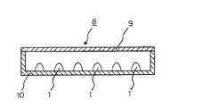
又、この発光素子1を組み込んだ面発光照明装置8は、図3に示されるように、内面を白色の平滑面等の光不透過性とした方形の保持ケース10の底面に、多数の発光素子1を、その外側に発光素子1の駆動のための電源及び回路等(図示せず。)を設けて配置し、保持ケース10の蓋部に相当する箇所に、乳白色としたアクリル板等の拡散板9を発光の均一化のために固定してなる。
【0028】
そして、面発光照明装置8を駆動して、発光素子1の半導体発光素子4に電圧を印加することにより青色光等を発光させ、その発光の一部を、蛍光体含有樹脂部5における波長変換材料としての本発明の蛍光体が吸収し、より長波長の光を発光し、一方、蛍光体に吸収されなかった青色光等との混色により演色性の高い発光が得られ、この光が拡散板9を透過して、図面上方に出射され、保持ケース10の拡散板9面内において均一な明るさの照明光が得られることとなる。
【0029】
【実施例】
以下、本発明を実施例によりさらに具体的に説明するが、本発明はその要旨を越えない限り以下の実施例に限定されるものではない。
【0030】
実施例1
M1源化合物としてCaCO3;0.0297モル、M2源化合物としてSc2O3;0.01モル、及びM3源化合物としてSiO2;0.03モル、並びに発光中心イオンの元素源化合物としてCe(OCOCH3)3;0.0003モルを純水と共に、アルミナ製容器及びビーズの湿式ボールミル中で粉砕、混合し、乾燥後、ナイロンメッシュを通過させた後、得られた粉砕混合物をアルミナ製坩堝中で、大気下、1400℃で2時間、加熱することにより焼成し、引き続いて、水洗浄、乾燥、及び分級処理を行うことにより蛍光体を製造した。
【0031】
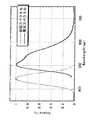
得られた蛍光体は、粉末X線回折による解析により、表1に示す組成のガーネット結晶構造の化合物を母体とし、該母体内に発光中心イオンとして3価のCeを含有するものであることが確認された。又、この蛍光体の発光スペクトルと励起スペクトルを測定し、図1に示した。この発光スペクトルから、JIS Z8722で規定されるXYZ表色系における色度座標xとyを、波長間隔5nmとして算出したところ、x=0.28、y=0.54であり、x+y=0.82であった。又、この蛍光体に、GaN系青色発光ダイオード(ピーク波長465nm)の青色光を照射し、その照射強度を調節したところ、その青色光を吸収して黄緑色光を発光し、蛍光体に吸収されなかったダイオードの青色光との混色によりやや青味がかった白色を示した。
【0032】
実施例2
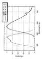
M1源化合物としてCaCO3;0.0147モルと、Mg(OH)2・3MgCO3・3H2O;Mgとして0.015モル、M2源化合物としてSc2O3;0.0075モルと、Y2O3;0.0025モルを、それぞれ用いた外は、実施例1と同様にして蛍光体を製造した。得られた蛍光体は、粉末X線回折による解析により、表1に示す組成のガーネット結晶構造の化合物を母体とし、該母体内に発光中心イオンとして3価のCeを含有するものであることが確認された。又、この蛍光体の発光スペクトルと励起スペクトルを測定し、図2に示した。この発光スペクトルから、実施例1と同様にして色度座標xとyを算出したところ、x=0.43、y=0.53であり、x+y=0.96であった。又、この蛍光体に、実施例1と同様にして青色光を照射し、その照射強度を調節したところ、その青色光を吸収して黄色光を発光し、蛍光体に吸収されなかった青色光との混色により白色を示した。
【0033】
実施例3
加熱処理の温度を1200℃とした外は、実施例1と同様にして蛍光体を製造した。得られた蛍光体は、粉末X線回折による解析により、表1に示す組成のガーネット結晶構造の化合物を母体とし、該母体内に発光中心イオンとして3価のCeを含有するものであることが確認された。又、この蛍光体の発光スペクトルから、実施例1と同様にして色度座標xとyを算出したところ、x=0.28、y=0.54であり、x+y=0.82であった。又、この蛍光体に、実施例1と同様にして青色光を照射し、その照射強度を調節したところ、その青色光を吸収して黄緑色光を発光し、蛍光体に吸収されなかった青色光との混色によりよりやや青味がかった白色を示した。
【0034】
実施例4
M2源化合物としてSc2O3;0.0050モルと、Y2O3;0.0050モルを用いた外は、実施例2と同様にして蛍光体を製造した。得られた蛍光体は、粉末X線回折による解析により、表1に示す組成のガーネット結晶構造の化合物を母体とし、該母体内に発光中心イオンとして3価のCeを含有するものであることが確認された。又、この蛍光体の発光スペクトルから、実施例1と同様にして色度座標xとyを算出したところ、x=0.47、y=0.50であり、x+y=0.97であった。又、この蛍光体に、実施例1と同様にして青色光を照射し、その照射強度を調節したところ、その青色光を吸収して黄色光を発光し、蛍光体に吸収されなかった青色光との混色により白色を示した。
【0035】
実施例5
M2源化合物としてSc2O3;0.0050モルと、Lu2O3;0.0050モルを用いた外は、実施例2と同様にして蛍光体を製造した。得られた蛍光体は、粉末X線回折による解析により、表1に示す組成のガーネット結晶構造の化合物を母体とし、該母体内に発光中心イオンとして3価のCeを含有するものであることが確認された。又、この蛍光体の発光スペクトルから、実施例1と同様にして色度座標xとyを算出したところ、x=0.45、y=0.53であり、x+y=0.98であった。又、この蛍光体に、実施例1と同様にして青色光を照射し、その照射強度を調節したところ、その青色光を吸収して黄色光を発光し、蛍光体に吸収されなかった青色光との混色により白色を示した。
【0036】
実施例6
M1源化合物としてCaCO3;0.0147モルと、ZnO;0.015モルを用いた外は、実施例1と同様にして蛍光体を製造した。得られた蛍光体は、粉末X線回折による解析により、表1に示す組成のガーネット結晶構造の化合物を母体とし、該母体内に発光中心イオンとして3価のCeを含有するものであることが確認された。又、この蛍光体の発光スペクトルから、実施例1と同様にして色度座標xとyを算出したところ、x=0.29、y=0.54であり、x+y=0.83であった。又、この蛍光体に、実施例1と同様にして青色光を照射し、その照射強度を調節したところ、その青色光を吸収して黄緑色光を発光し、蛍光体に吸収されなかった青色光との混色によりやや青味がかった白色を示した。
【0037】
【表1】
【発明の効果】
本発明によれば、製造が容易であると共に、演色性の高い発光素子を得ることができる蛍光体、及び、その蛍光体を用いた発光素子、並びに、その発光素子を光源とする画像表示装置及び照明装置を提供することができる。
【図面の簡単な説明】
【図1】 本発明の実施例1で得られた蛍光体の発光スペクトル及び励起スペクトルである。
【図2】 本発明の実施例2で得られた蛍光体の発光スペクトル及び励起スペクトルである。
【図3】 波長変換材料としての本発明の蛍光体と、半導体発光素子とから構成される発光素子の一実施例を示す模式的断面図である。
【図4】 図3に示す発光素子を組み込んだ面発光照明装置の一実施例を示す模式的断面図である。
【符号の説明】
1;発光素子
2;マウントリード
3;インナーリード
4;半導体発光素子
5;蛍光体含有樹脂部
6;導電性ワイヤー
7;モールド部材
8;面発光照明装置
9;拡散板
10;保持ケース[0001]
BACKGROUND OF THE INVENTION
The present invention relates to a phosphor in which the base compound contains an emission center ion, and more specifically, as a wavelength conversion material, it absorbs light in the range of ultraviolet light to visible light and emits visible light having a longer wavelength, thereby producing a light emitting diode ( LED) and relatesto a fluorescentbody capable of constituting a high color rendering light emitting device by combining a laser diode (LD) a semiconductor light emitting element such as.
[0002]
[Prior art]
Conventionally, a white light emitting element configured by combining a gallium nitride (GaN) blue light emitting diode as a semiconductor light emitting element and a phosphor as a wavelength conversion material has a feature of low power consumption and long life. Taking advantage of this, it is attracting attention as a light source for image display devices and lighting devices.
[0003]
In this light emitting device, since the phosphor used there absorbs visible light in the blue region emitted by the GaN-based blue light emitting diode and emits yellow light, color mixing with the blue light of the diode not absorbed by the phosphor As a phosphor, typically, a yttrium-aluminum composite oxide (Y3 Al5 O12 ) is used as a host substance, and a luminescent center ion is contained in the host body. A phosphor containing cerium (Ce) is known, but this phosphor is not always easy to manufacture because of its high firing temperature.
[0004]
[Problems to be solved by the invention]
The present invention has been made in view of the above-described prior art, and has been made to develop a phosphor that can be easily manufactured, and further, a phosphor capable of obtaining a light emitting element with higher color rendering properties. Anobject of the present inventionis to provide a phosphor that can be easily produced and can obtain a luminescent dye having high color rendering properties.
[0005]
[Means for Solving the Problems]
As a result of intensive studies to solve the above-mentioned problems, the inventors of the present invention are composed ofdivalent, trivalent, and tetravalent metal elements, Ca as the divalent metal element, Sc as the trivalent metal element, and tetravalent metal. It has been found that a phosphor havinga garnet crystal structurecontaining Si as an essential metal element as a matrix and containing cerium as a luminescent center ion in the matrix can achieve the above-mentioned object. Therefore, the gist of the present invention is a phosphor comprising, as a matrix, a compound having a garnet crystal structure represented by the following general formula (I), andCe as a luminescent center ion.
[0006]
M1a M2b M3c Od (I)
[In the formula (I),M1is a divalent metal element selected from the group consisting of Ca or Ca and Mg and Zn, and M2isselected from the group consistingof Sc or Sc and Al, Y and Lu.Isa selected trivalent metal element, and M3is a tetravalent metal element selected from the group consisting of Si or Si and Ge and Sn. a is 2.7 to 3.3, b is 1.8 to 2.2, c is 2.7 to 3.3, and d is a number in the range of 11.0 to 13.0. ]
[0007]
DETAILED DESCRIPTION OF THE INVENTION
The phosphor of the present invention is based on a compound having a garnet crystal structure represented by the general formula (I), and is generally a complex oxide containing metal elements of M1 , M2 , and M3. In the compounds of the known garnet crystal structure represented by M13 M22 M33 O12 , in the present invention, M1 is divalent, M2 is trivalent, and M3 is 4 A compound that is a valent metal element is used as a base material of a phosphor.
[0008]
That is, in the present invention, for example, a composite oxide such as Y3 Al5 O12 is known as a phosphor matrix, and M1 is divalent, M2 is trivalent, and M3 is tetravalent. Although a compound having a garnet crystal structure of a metal element is also known as described above, the characteristics as a phosphor vary greatly depending on the element constituting the host and its valence, while this M1 is divalent. , Which is based on the finding that a compound having a garnet crystal structure in which M2 is trivalent and M3 is a tetravalent metal element is excellent as a matrix of the phosphor.
[0009]
Here, the divalent metal element M1 in the formula (I) is at least one selected from the group consisting of Mg, Ca, Zn, Sr, Cd, and Ba from the viewpoint of luminous efficiency and the like. Is more preferable, Mg, Ca, or Zn is further preferable, and Ca, or Ca and Mg are particularly preferable.
[0010]
The trivalent metal element M2 in the formula (I) is at least one selected from the group consisting of Al, Sc, Ga, Y, In, La, Gd, and Lu from the same aspect. Of these, Al, Sc, Y, or Lu are more preferable, and Sc, or Sc and Y, or Sc and Lu are particularly preferable.
[0011]
The tetravalent metal element M3 in the formula (I) is preferably at least one selected from the group consisting of Si, Ti, Ge, Zr, Sn, and Hf from the same aspect. More preferred is Si, Ge, or Sn, and particularly preferred is Si.
[0012]
The garnet crystal structure is generally a body-centered cubic crystal in which a in formula (I) is 3, b is 2, c is 3, and d is 12, as described above. Is obtained by substituting the element of the luminescent center ion, which will be described later, into the position of the crystal lattice of one of the metal elements of M1 , M2 , or M3 , or by arranging it in the gap between the crystal lattices. In I), a may be 3, b is 2, c is 3, and d may not be 12. Therefore, a is 2.7 to 3.3, b is 1.8 to 2.2, c Is a number in the range of 2.7 to 3.3, d is in the range of 11.0 to 13.0, a is 2.9 to 3.1, b is 1.95 to 2.05, c is 2 Each is preferably a number in the range of .9 to 3.1, and d is preferably a number in the range of 11.65 to 12.35.
[0013]
The luminescent center ions contained in the compound matrix having the garnet crystal structure are Cr, Mn, Fe, Co, Ni, Cu, Ce, Pr, Nd, Sm, Eu, and Tb from the same surface as described above. It is preferably at least one divalent to tetravalent element selected from the group consisting of Dy, Ho, Er, Tm, and Yb, divalent Mn, trivalent Ce, and 2-3 trivalent Eu. Or trivalent Tb is more preferable, and trivalent Ce is particularly preferable.
[0014]
The phosphor of the present invention comprises a divalent metal element M1 source compound, a trivalent metal element M2 source compound, a tetravalent metal element M3 source compound in the general formula (I), and a luminescent center. Ion element source compound is pulverized using a dry pulverizer such as a hammer mill, roll mill, ball mill, jet mill, etc., and then mixed by a mixer such as a ribbon blender, V-type blender, Henschel mixer, or the like. Then, these compounds are added into a medium such as water, and then pulverized and mixed using a wet pulverizer such as a medium agitating pulverizer. After the compound is pulverized by a dry pulverizer, the prepared pulverized mixture is heated by a wet method in which the slurry prepared by adding and mixing in a medium such as water is dried by spray drying or the like. And then baked.
[0015]
Among these pulverization and mixing methods, in particular, in the element source compound of the luminescent center ion, it is preferable to use a liquid medium because it is necessary to uniformly mix and disperse a small amount of the compound over the whole. The latter wet method is preferable from the viewpoint of obtaining uniform mixing in the element source compound as a whole, and the heat treatment method is usually 1000 to 1600 ° C. in a heat-resistant container such as a crucible or tray made of alumina or quartz. The heating is preferably performed at a temperature of 1200 to 1500 ° C. for 10 minutes to 24 hours in a single or mixed atmosphere of a gas such as air, oxygen, carbon monoxide, carbon dioxide, nitrogen, hydrogen, and argon. In addition, after heat processing, washing | cleaning, drying, a classification process, etc. are made | formed as needed.
[0016]
As the heating atmosphere, an atmosphere necessary for obtaining an ion state (valence) in which the element of the emission center ion contributes to light emission is selected. For example, in the case of trivalent Eu or the like, the atmosphere, oxygen In the case of trivalent Ce or the like in an oxidizing or neutral atmosphere such as nitrogen or argon, divalent Mn or divalent in a weakly oxidizing or weakly reducing atmosphere such as air, carbon monoxide, carbon dioxide or nitrogen In the case of Eu, trivalent Tb, etc., neutral or reducing atmosphere such as carbon monoxide, nitrogen, hydrogen, argon, etc. is employed.
[0017]
Here, as the M1 source compound, the M2 source compound, the M3 source compound, and the element source compound of the luminescent center ion, the elements of M1 , M2 , M3 , and the luminescent center ion are used. Examples include oxides, hydroxides, carbonates, nitrates, sulfates, oxalates, carboxylates, halides, etc. Among these, reactivity to composite oxides, and NOx during firing , SOx and other non-generating factors are selected.
[0018]
Regarding the Mg, Ca, and Zn that are preferred as the divalent metal element M1 , specific examples of those M1 source compounds include MgO, Mg (OH)2 , MgCO3. Mg (OH)2 .3MgCO3 .3H2 O, Mg (NO3 )2 .6H2 O, MgSO4 , Mg (OCO)2 .2H2 O, Mg (OCOCH3 )2 .4H2 O, MgCl2 and the like, and Ca source compounds include CaO, Ca (OH)2 , CaCO3 , Ca (NO3 )2 .4H2 O, CaSO4 .2H2 O, Ca (OCO)2 .H2 O. , Ca (OCOCH3 )2 .H2 O, CaCl2 and the like, and as the Zn source compound, ZnO, Zn (OH)2 , ZnCO3 , Zn (NO3 )2 , Zn (OCO)2 , Zn Examples thereof include (OCOCH3 )2 and ZnCl2 .
[0019]
Further, regarding the Al, Sc, Y, and Lu that are preferable as the trivalent metal element M2 , specific examples of their M2 source compounds include Al2 O3 , Al (OH)3 , AlOOH, Al (NO3 )3 .9H2 O, Al2 (SO4 )3 , AlCl3, etc., and Sc source compounds include Sc2 O3 , Sc (OH)3 , Sc2 (CO3 )3 , Sc (NO3 )3 , Sc2 (SO4 )3 , Sc2 (OCO)6 , Sc (OCOCH3 )3 , ScCl3, etc. Y2 O3 , Y (OH)3 , Y2 (CO3 )3 , Y (NO3 )3 , Y2 (SO4 )3 , Y2 (OCO)6 , YCl3, etc., and a Lu source Examples of the compound include Lu2 O3 , Lu2 (SO4 )3 , and LuCl3 .
[0020]
Further, regarding the Si, Ge, and Sn preferred as the tetravalent metal element M3 , specific examples of the M3 source compounds include SiO2 , H4 SiO4 , Si (OCOCH3 )4 and the like, and Ge source compounds include GeO2 , Ge (OH)4 , Ge (OCOCH3 )4 and GeCl4 , and Sn source compounds include SnO2 and SnO.2 , nH2 O, Sn (NO3 )4 , Sn (OCOCH3 )4 , SnCl4 and the like can be mentioned.
[0021]
Further, with respect to Mn, Ce, Eu, and Tb, which are preferable as elements of the luminescent center ion, specific examples of their element source compounds include MnO2 , Mn2 O3 , Mn3 O4 , MnOOH, MnCO3 , Mn (NO3 )2 , MnSO4 , Mn (OCOCH3 )2 , Mn (OCOCH3 )3 , MnCl2 , MnCi3, etc., and Ce source compounds include Ce2. O3 , CeO2 , Ce (OH)3 , Ce (OH)4 , Ce2 (CO3 )3 , Ce (NO3 )3 , Ce2 (SO4 )3 , Ce (SO4 )2 , Ce2 (OCO)6 , Ce (OCOCH3 )3 , CeCl3 , CeCl4, etc., and Eu source compounds include Eu2 O3 , Eu2 (SO4 )3 , Eu2 (OCO)6 , EuCl2. , EuCl3 etc., also the Tb source compound, Tb23, Tb 4 O 7, Tb 2 (CO 3) 3, Tb 2 (SO 4) 3,
[0022]
As described above, the phosphor of the present invention comprising the compound having the garnet crystal structure as a host and containing the emission center ion in the host, the content of the emission center ion is 0.0001 per one amount of the host compound. It is preferable that it is -0.3 mol, and it is still more preferable that it is 0.001-0.15 mol. If the content of the luminescent center ion is less than the above range, the emission intensity tends to decrease. On the other hand, if the content exceeds the above range, the emission intensity tends to decrease due to a phenomenon called concentration quenching.
[0023]
In addition, when the phosphor of the present invention is used as a wavelength conversion material, for example, when the emission center ion is trivalent Ce, it absorbs light in the range from ultraviolet light to visible light in the blue region, and is green. It emits visible light having a longer wavelength such as yellow, orange, red, or an intermediate color thereof. The sum of the chromaticity coordinates x and y when the emission color when only the emission of the phosphor is spectroscopically measured without the scattering component of the excitation light is expressed in the XYZ color system defined by JIS Z8701 is It is preferable to satisfy (x + y) ≧ 0.6, and it is more preferable to satisfy (x + y) ≧ 0.8.
[0024]
Accordingly, when the phosphor of the present inventionis combined with a semiconductor light emitting device such asan LED or LD toforma light emitting device, it absorbs light in the range from ultraviolet light to visible light emitted fromthe semiconductor light emitting device and emits longer wavelength visible light.It becomes a light emitting elementwith high color rendering properties, and is suitable as a light source for an image display device such as a color liquid crystal display or a lighting device such as a surface emitting device.
[0025]
This light-emitting element will be described with reference to the drawings. FIG. 2 is a schematic cross-sectional view showing an embodiment of a light-emitting element composed of the phosphor of the present invention as a wavelength conversion material and a semiconductor light-emitting element. FIG. 4 is a schematic cross-sectional view showing an embodiment of a surface-emitting illumination device incorporating the light-emitting element shown in FIG. 2. In FIGS. 2 and 3, 1 is a light-emitting element, 2 is a mount lead, 3 is an inner lead, 4 is a semiconductor light emitting element, 5 is a phosphor-containing resin part, 6 is a conductive wire, 7 is a mold member, 8 is a surface emitting illumination device, 9 is a diffusion plate, and 10 is a holding case.
[0026]
As shown in FIG. 2, the
[0027]
Further, as shown in FIG. 3, the surface emitting illumination device 8 incorporating the
[0028]
Then, the surface-emitting illumination device 8 is driven to apply blue voltage to the semiconductor light-emitting
[0029]
【Example】
EXAMPLES Hereinafter, the present invention will be described more specifically with reference to examples. However, the present invention is not limited to the following examples unless it exceeds the gist.
[0030]
Example 1
CaCO3 as the M1 source compound; 0.0297 mol, Sc2 O3 as the M2 source compound; 0.01 mol, and SiO2 as the M3 source compound; 0.03 mol, and the element source compound of the luminescent center ion Ce (OCOCH3 )3 ; 0.0003 mol together with pure water in an alumina container and beads in a wet ball mill, mixed, dried, passed through a nylon mesh, and the resulting pulverized mixture was treated with alumina. The phosphor was manufactured by heating in a crucible at 1400 ° C. for 2 hours in the atmosphere, followed by washing with water, drying, and classification.
[0031]
According to the analysis by powder X-ray diffraction, the obtained phosphor is based on a compound having a garnet crystal structure having the composition shown in Table 1, and contains trivalent Ce as a luminescent center ion. confirmed. The emission spectrum and excitation spectrum of this phosphor were measured and shown in FIG. From this emission spectrum, when the chromaticity coordinates x and y in the XYZ color system defined by JIS Z8722 were calculated with a wavelength interval of 5 nm, x = 0.28, y = 0.54, and x + y = 0. 82. The phosphor is irradiated with blue light from a GaN-based blue light-emitting diode (peak wavelength: 465 nm), and when the intensity of irradiation is adjusted, the blue light is absorbed and yellow-green light is emitted, which is absorbed by the phosphor. The white color was slightly bluish due to the color mixing with the blue light of the diode that was not done.
[0032]
Example 2
CaCO3 ; 0.0147 mol as an M1 source compound; Mg (OH)2 .3MgCO3 .3H2 O; 0.015 mol as Mg; Sc2 O3 as an M2 source compound; 0.0075 mol; A phosphor was produced in the same manner as in Example 1 except that 0.0025 mol of Y2 O3 was used. According to the analysis by powder X-ray diffraction, the obtained phosphor is based on a compound having a garnet crystal structure having the composition shown in Table 1, and contains trivalent Ce as a luminescent center ion. confirmed. The emission spectrum and excitation spectrum of this phosphor were measured and shown in FIG. From this emission spectrum, chromaticity coordinates x and y were calculated in the same manner as in Example 1. As a result, x = 0.43, y = 0.53, and x + y = 0.96. Further, when this phosphor was irradiated with blue light in the same manner as in Example 1 and the irradiation intensity was adjusted, the blue light was absorbed to emit yellow light, and the blue light that was not absorbed by the phosphor. A white color was indicated by the color mixture with the.
[0033]
Example 3
A phosphor was manufactured in the same manner as in Example 1 except that the temperature of the heat treatment was 1200 ° C. According to the analysis by powder X-ray diffraction, the obtained phosphor is based on a compound having a garnet crystal structure having the composition shown in Table 1, and contains trivalent Ce as a luminescent center ion. confirmed. Further, when the chromaticity coordinates x and y were calculated from the emission spectrum of this phosphor in the same manner as in Example 1, x = 0.28, y = 0.54, and x + y = 0.82. . Further, when this phosphor was irradiated with blue light in the same manner as in Example 1 and the irradiation intensity was adjusted, the blue light was absorbed to emit yellow-green light, and the blue that was not absorbed by the phosphor. A slightly bluish white color was exhibited due to color mixing with light.
[0034]
Example 4
A phosphor was produced in the same manner as in Example 2 except that Sc2 O3 ; 0.0050 mol and Y2 O3 ; 0.0050 mol were used as the M2 source compound. According to the analysis by powder X-ray diffraction, the obtained phosphor is based on a compound having a garnet crystal structure having the composition shown in Table 1, and contains trivalent Ce as a luminescent center ion. confirmed. Further, when the chromaticity coordinates x and y were calculated from the emission spectrum of the phosphor in the same manner as in Example 1, x = 0.47, y = 0.50, and x + y = 0.97. . Further, when this phosphor was irradiated with blue light in the same manner as in Example 1 and the irradiation intensity was adjusted, the blue light was absorbed to emit yellow light, and the blue light that was not absorbed by the phosphor. A white color was indicated by the color mixture with the.
[0035]
Example 5
A phosphor was produced in the same manner as in Example 2 except that Sc2 O3 ; 0.0050 mol and Lu2 O3 ; 0.0050 mol were used as the M2 source compound. According to the analysis by powder X-ray diffraction, the obtained phosphor is based on a compound having a garnet crystal structure having the composition shown in Table 1, and contains trivalent Ce as a luminescent center ion. confirmed. Further, when the chromaticity coordinates x and y were calculated from the emission spectrum of this phosphor in the same manner as in Example 1, x = 0.45, y = 0.53, and x + y = 0.98. . Further, when this phosphor was irradiated with blue light in the same manner as in Example 1 and the irradiation intensity was adjusted, the blue light was absorbed to emit yellow light, and the blue light that was not absorbed by the phosphor. A white color was indicated by the color mixture with the.
[0036]
Example 6
A phosphor was produced in the same manner as in Example 1 except that CaCO3 ; 0.0147 mol and ZnO; 0.015 mol were used as the M1 source compound. According to the analysis by powder X-ray diffraction, the obtained phosphor is based on a compound having a garnet crystal structure having the composition shown in Table 1, and contains trivalent Ce as a luminescent center ion. confirmed. Further, when the chromaticity coordinates x and y were calculated from the emission spectrum of this phosphor in the same manner as in Example 1, x = 0.29, y = 0.54, and x + y = 0.83. . Further, when this phosphor was irradiated with blue light in the same manner as in Example 1 and the irradiation intensity was adjusted, the blue light was absorbed to emit yellow-green light, and the blue that was not absorbed by the phosphor. A white color slightly bluish due to the color mixture with light.
[0037]
[Table 1]
【The invention's effect】
According to the present invention, a phosphor that can be easily manufactured and can obtain a light emitting element with high color rendering properties, a light emitting element using the phosphor, and an image display apparatus using the light emitting element as a light source. And a lighting device can be provided.
[Brief description of the drawings]
FIG. 1 is an emission spectrum and excitation spectrum of a phosphor obtained in Example 1 of the present invention.
FIG. 2 shows an emission spectrum and an excitation spectrum of the phosphor obtained in Example 2 of the present invention.
FIG. 3 is a schematic cross-sectional view showing an embodiment of a light emitting device comprising a phosphor of the present invention as a wavelength conversion material and a semiconductor light emitting device.
4 is a schematic cross-sectional view showing one embodiment of a surface-emitting illumination device incorporating the light-emitting element shown in FIG.
[Explanation of symbols]
DESCRIPTION OF
Claims (9)
Translated fromJapaneseMM11aaMM22bbMM3ThreeccOOdd(I)(I)
[式[formula(I)(I)中、MMedium, M11はCa、又はCa並びにMg及びZnからなる群から選ばれた2価の金属元素であり、MIs a divalent metal element selected from the group consisting of Ca or Ca and Mg and Zn;22はSc、又はSc並びにAl、Y、及びLuからなる群から選ばれた3価の金属元素であり、MIs a trivalent metal element selected from the group consisting of Sc or Sc and Al, Y, and Lu;3ThreeはSi、又はSi並びにGe及びSnからなる群から選ばれた4価の金属元素である。aは2.7〜3.3、bは1.8〜2.2、cは2.7〜3.3、dは11.0〜13.0の範囲の数である。]Is a tetravalent metal element selected from the group consisting of Si or Si and Ge and Sn. a is 2.7 to 3.3, b is 1.8 to 2.2, c is 2.7 to 3.3, and d is a number in the range of 11.0 to 13.0. ]
M1a M2b M3c Od (I)
[式(I) 中、M1 はCa、CaとMg又はCaとZnである2価の金属元素であり、M2 はSc、ScとY又はScとLuである3価の金属元素であり、M3 は4価の金属元素であるSiである。aは2.7〜3.3、bは1.8〜2.2、cは2.7〜3.3、dは11.0〜13.0の範囲の数である。]A phosphor comprising a compound having a garnet crystal structure represented by the following general formula (I) as a matrix, and Ce as a luminescent center ion in the matrix.
M1a M2b M3c Od (I)
[In formula (I), M1 is a divalent metal element of Ca, Ca and Mg or Ca and Zn, and M2 is a trivalent metal element of Sc, Sc and Y or Sc and Lu. M3 is Si which is a tetravalent metal element. a is 2.7 to 3.3, b is 1.8 to 2.2, c is 2.7 to 3.3, and d is a number in the range of 11.0 to 13.0. ]
M1a M2b M3c Od (I)
[式(I)中、M1はCa、M2はSc、M3はSiであり、aは2.7〜3.3、bは1.8〜2.2、cは2.7〜3.3、dは11.0〜13.0の範囲の数である。]A phosphor comprising a compound having a garnet crystal structure represented by the following general formula (I) as a matrix, and Ce as a luminescent center ion in the matrix.
M1a M2b M3c Od (I)
[In the formula (I), M1 is Ca, M2 is Sc, M3 is Si, a is 2.7 to 3.3, b is 1.8 to 2.2, and c is 2.7 to 2.7 3.3 and d are numbers in the range of 11.0 to 13.0. ]
M1a M2b M3c Od (I)
[式(I)中、M1はCaとMg、M2はScとY、M3はSiであり、aは2.7〜3.3、bは1.8〜2.2、cは2.7〜3.3、dは11.0〜13.0の範囲の数である。]A phosphor comprising a compound having a garnet crystal structure represented by the following general formula (I) as a matrix, and Ce as a luminescent center ion in the matrix.
M1a M2b M3c Od (I)
[In the formula (I), M1 is Ca and Mg, M2 is Sc and Y, M3 is Si, a is 2.7 to 3.3, b is 1.8 to 2.2, and c is 2.7 to 3.3, d is a number in the range of 11.0 to 13.0. ]
M1a M2b M3c Od (I)
[式(I)中、M1はCaとMg、M2はScとLu、M3はSiであり、aは2.7〜3.3、bは1.8〜2.2、cは2.7〜3.3、dは11.0〜13.0の範囲の数である。]A phosphor comprising a compound having a garnet crystal structure represented by the following general formula (I) as a matrix, and Ce as a luminescent center ion in the matrix.
M1a M2b M3c Od (I)
[In the formula (I), M1 is Ca and Mg, M2 is Sc and Lu, M3 is Si, a is 2.7 to 3.3, b is 1.8 to 2.2, c is 2.7 to 3.3, d is a number in the range of 11.0 to 13.0. ]
M1a M2b M3c Od (I)
[式(I)中、M1はCaとZn、M2はSc、M3はSiであり、aは2.7〜3.3、bは1.8〜2.2、cは2.7〜3.3の範囲の数である。]A phosphor comprising a compound having a garnet crystal structure represented by the following general formula (I) as a matrix, and Ce as a luminescent center ion in the matrix.
M1a M2b M3c Od (I)
[In the formula (I), M1 is Ca and Zn, M2 is Sc, M3 is Si, a is 2.7 to 3.3, b is 1.8 to 2.2, and c is 2. It is a number in the range of 7 to 3.3. ]
Priority Applications (4)
| Application Number | Priority Date | Filing Date | Title |
|---|---|---|---|
| JP2001257420AJP4032682B2 (en) | 2001-08-28 | 2001-08-28 | Phosphor |
| US11/560,007US20070085466A1 (en) | 2001-08-28 | 2006-11-15 | Phosphor, light emitting device using phosphor, and display and lighting system using light emitting device |
| US12/124,595US7790058B2 (en) | 2001-08-28 | 2008-05-21 | Phosphor, light emitting device using phosphor, and display and lighting system using light emitting device |
| US12/843,454US20100283383A1 (en) | 2001-08-28 | 2010-07-26 | Phosphor, light emitting device using phosphor, and display and lighting system using light emitting device |
Applications Claiming Priority (1)
| Application Number | Priority Date | Filing Date | Title |
|---|---|---|---|
| JP2001257420AJP4032682B2 (en) | 2001-08-28 | 2001-08-28 | Phosphor |
Related Child Applications (2)
| Application Number | Title | Priority Date | Filing Date |
|---|---|---|---|
| JP2007144456ADivisionJP4656090B2 (en) | 2007-05-31 | 2007-05-31 | LIGHT EMITTING ELEMENT AND IMAGE DISPLAY DEVICE AND LIGHTING DEVICE USING THE SAME |
| JP2007215972ADivisionJP4656109B2 (en) | 2007-08-22 | 2007-08-22 | Phosphor |
Publications (2)
| Publication Number | Publication Date |
|---|---|
| JP2003064358A JP2003064358A (en) | 2003-03-05 |
| JP4032682B2true JP4032682B2 (en) | 2008-01-16 |
Family
ID=19085084
Family Applications (1)
| Application Number | Title | Priority Date | Filing Date |
|---|---|---|---|
| JP2001257420AExpired - Fee RelatedJP4032682B2 (en) | 2001-08-28 | 2001-08-28 | Phosphor |
Country Status (2)
| Country | Link |
|---|---|
| US (3) | US20070085466A1 (en) |
| JP (1) | JP4032682B2 (en) |
Cited By (1)
| Publication number | Priority date | Publication date | Assignee | Title |
|---|---|---|---|---|
| WO2013005356A1 (en) | 2011-07-05 | 2013-01-10 | パナソニック株式会社 | Rare-earth aluminum garnet type fluorescent substance and light-emitting device obtained using same |
Families Citing this family (51)
| Publication number | Priority date | Publication date | Assignee | Title |
|---|---|---|---|---|
| JP4032682B2 (en) | 2001-08-28 | 2008-01-16 | 三菱化学株式会社 | Phosphor |
| US7189340B2 (en) | 2004-02-12 | 2007-03-13 | Mitsubishi Chemical Corporation | Phosphor, light emitting device using phosphor, and display and lighting system using light emitting device |
| US7252787B2 (en) | 2003-10-29 | 2007-08-07 | General Electric Company | Garnet phosphor materials having enhanced spectral characteristics |
| US7094362B2 (en) | 2003-10-29 | 2006-08-22 | General Electric Company | Garnet phosphor materials having enhanced spectral characteristics |
| US7442326B2 (en) | 2003-10-29 | 2008-10-28 | Lumination Llc | Red garnet phosphors for use in LEDs |
| DE10360546A1 (en)* | 2003-12-22 | 2005-07-14 | Patent-Treuhand-Gesellschaft für elektrische Glühlampen mbH | Phosphor and light source with such phosphor |
| JP2005243699A (en)* | 2004-02-24 | 2005-09-08 | Mitsubishi Chemicals Corp | LIGHT EMITTING ELEMENT, IMAGE DISPLAY DEVICE, AND LIGHTING DEVICE |
| KR100605212B1 (en)* | 2004-04-07 | 2006-07-31 | 엘지이노텍 주식회사 | Phosphor and White Light Emitting Diode Using the Same |
| JP4492189B2 (en)* | 2004-04-07 | 2010-06-30 | 日亜化学工業株式会社 | Light emitting device |
| US7830472B2 (en) | 2004-04-26 | 2010-11-09 | Mitsubishi Chemical Corporation | Blue color composition for color filter, color filter, and color image display device |
| KR100658700B1 (en) | 2004-05-13 | 2006-12-15 | 서울옵토디바이스주식회사 | Light emitting device combining RGB light emitting element and phosphor |
| US8308980B2 (en) | 2004-06-10 | 2012-11-13 | Seoul Semiconductor Co., Ltd. | Light emitting device |
| KR100665299B1 (en) | 2004-06-10 | 2007-01-04 | 서울반도체 주식회사 | Emitting material |
| KR100665298B1 (en) | 2004-06-10 | 2007-01-04 | 서울반도체 주식회사 | Light emitting device |
| JP5226929B2 (en) | 2004-06-30 | 2013-07-03 | 三菱化学株式会社 | LIGHT EMITTING ELEMENT, LIGHTING DEVICE USING SAME, AND IMAGE DISPLAY DEVICE |
| US7737623B2 (en) | 2004-06-30 | 2010-06-15 | Mitsubishi Chemical Corporation | Light emitting device, lighting system, backlight unit for display device, and display device |
| JP2006019409A (en) | 2004-06-30 | 2006-01-19 | Mitsubishi Chemicals Corp | LIGHT EMITTING DEVICE, LIGHTING USING SAME, DISPLAY BACKLIGHT AND DISPLAY |
| KR20070048661A (en) | 2004-06-30 | 2007-05-09 | 미쓰비시 가가꾸 가부시키가이샤 | Phosphor, Light-Emitting Element Using the Same, and Image Display Device, Illumination Device |
| KR101267284B1 (en)* | 2004-10-15 | 2013-08-07 | 미쓰비시 가가꾸 가부시키가이샤 | Fluorescent material, fluorescent device using the same, and image display device and lighting equipment |
| JP4904766B2 (en)* | 2004-10-15 | 2012-03-28 | 三菱化学株式会社 | Phosphor, light-emitting device using the same, image display device, and lighting device |
| JP2006232935A (en)* | 2005-02-23 | 2006-09-07 | Sumitomo Chemical Co Ltd | Method for producing silicate phosphor |
| WO2006098450A1 (en) | 2005-03-18 | 2006-09-21 | Mitsubishi Chemical Corporation | Light-emitting device, white light-emitting device, illuminator, and image display |
| JP5721921B2 (en)* | 2005-03-28 | 2015-05-20 | 三菱化学株式会社 | White light emitting device and lighting device |
| JP4972957B2 (en)* | 2005-04-18 | 2012-07-11 | 三菱化学株式会社 | Phosphor, light-emitting device using the same, image display device, and lighting device |
| JP5098221B2 (en)* | 2005-05-24 | 2012-12-12 | 三菱化学株式会社 | LIGHT EMITTING DEVICE, LIGHTING DEVICE, DISPLAY BACKLIGHT AND DISPLAY |
| JP2007049114A (en) | 2005-05-30 | 2007-02-22 | Sharp Corp | Light emitting device and manufacturing method thereof |
| JP4832995B2 (en)* | 2005-09-01 | 2011-12-07 | シャープ株式会社 | Light emitting device |
| KR101258397B1 (en)* | 2005-11-11 | 2013-04-30 | 서울반도체 주식회사 | Copper-Alkaline-Earth-Silicate mixed crystal phosphors |
| KR101055772B1 (en) | 2005-12-15 | 2011-08-11 | 서울반도체 주식회사 | Light emitting device |
| KR100875443B1 (en) | 2006-03-31 | 2008-12-23 | 서울반도체 주식회사 | Light emitting device |
| KR100968844B1 (en)* | 2006-06-29 | 2010-07-09 | 서울반도체 주식회사 | Light emitting device |
| KR101258227B1 (en) | 2006-08-29 | 2013-04-25 | 서울반도체 주식회사 | Light emitting device |
| US7579765B2 (en)* | 2006-10-06 | 2009-08-25 | Nemoto & Company, Ltd. | Orange-emitting phosphor |
| JP5367218B2 (en) | 2006-11-24 | 2013-12-11 | シャープ株式会社 | Method for manufacturing phosphor and method for manufacturing light emitting device |
| TWI384052B (en)* | 2007-07-25 | 2013-02-01 | Univ Nat Chiao Tung | A novel phosphor and fabrication of the same |
| TWI363085B (en)* | 2007-07-26 | 2012-05-01 | Univ Nat Chiao Tung | A novel phosphor and fabrication of the same |
| RU2467051C2 (en) | 2007-08-22 | 2012-11-20 | Сеул Семикондактор Ко., Лтд. | Luminophores based on nonstoichiometric tetragonal silicates of copper and alkali-earth metal and method for production thereof |
| KR101055769B1 (en) | 2007-08-28 | 2011-08-11 | 서울반도체 주식회사 | Light-emitting device adopting non-stoichiometric tetra-alkaline earth silicate phosphor |
| JP2009124867A (en)* | 2007-11-15 | 2009-06-04 | Nidec Sankyo Corp | Motor |
| KR101055762B1 (en) | 2009-09-01 | 2011-08-11 | 서울반도체 주식회사 | Light-emitting device employing a light-emitting material having an oxyosilicate light emitter |
| DE102009030205A1 (en) | 2009-06-24 | 2010-12-30 | Litec-Lp Gmbh | Phosphors with Eu (II) -doped silicate luminophores |
| KR20120104377A (en)* | 2009-12-17 | 2012-09-20 | 코닌클리즈케 필립스 일렉트로닉스 엔.브이. | Light emitting diode device with luminescent material |
| CN102376860A (en) | 2010-08-05 | 2012-03-14 | 夏普株式会社 | Light emitting apparatus and method for manufacturing thereof |
| EP2760970B1 (en) | 2011-09-30 | 2015-12-16 | General Electric Company | Phosphor materials and related devices |
| US8506104B1 (en) | 2012-03-28 | 2013-08-13 | General Electric Company | Phosphors for LED lamps |
| JP5527445B2 (en)* | 2013-02-08 | 2014-06-18 | 三菱化学株式会社 | LIGHT EMITTING ELEMENT, LIGHTING DEVICE USING SAME, AND IMAGE DISPLAY DEVICE |
| JPWO2015045260A1 (en)* | 2013-09-30 | 2017-03-09 | パナソニックIpマネジメント株式会社 | Phosphor and light emitting device, illumination light source, and illumination device using the same |
| CN105814171A (en)* | 2013-12-04 | 2016-07-27 | 默克专利有限公司 | Eu2+-activated luminescent materials |
| JP6341480B2 (en)* | 2014-04-16 | 2018-06-13 | 株式会社豊田自動織機 | Garnet-type oxide, method for producing the same, and solid electrolyte for secondary battery and secondary battery using the same |
| CN105567236B (en)* | 2014-10-15 | 2018-07-20 | 有研稀土新材料股份有限公司 | Carbuncle type fluorescent powder and preparation method and device comprising the fluorescent powder |
| CN119529836A (en)* | 2024-09-04 | 2025-02-28 | 江西理工大学 | A blue-cyan light emitting luminescent material, preparation method and low blue light LED light source made thereof |
Family Cites Families (15)
| Publication number | Priority date | Publication date | Assignee | Title |
|---|---|---|---|---|
| US3468801A (en)* | 1966-01-21 | 1969-09-23 | Wayne D Wilson | Synthesis of garnet at high pressures |
| NL181063C (en)* | 1976-05-13 | 1987-06-01 | Philips Nv | LUMINESCENT SCREEN; LOW-PRESSURE MERCURY DISCHARGE LAMP; PROCESS FOR PREPARING A LUMINESCENT MATERIAL |
| JP2526407B2 (en) | 1993-12-27 | 1996-08-21 | 科学技術庁無機材質研究所長 | Single crystal for tunable laser |
| JP3065258B2 (en) | 1996-09-30 | 2000-07-17 | 日亜化学工業株式会社 | Light emitting device and display device using the same |
| DE19951790A1 (en) | 1999-10-27 | 2001-05-03 | Patent Treuhand Ges Fuer Elektrische Gluehlampen Mbh | Fluorescent for light sources and associated light source |
| WO2001008452A1 (en)* | 1999-07-23 | 2001-02-01 | Patent-Treuhand-Gesellschaft für elektrische Glühlampen mbH | Luminous substance for a light source and light source associated therewith |
| EP1116419B1 (en)* | 1999-07-23 | 2004-10-06 | Osram Opto Semiconductors GmbH | Luminescent array, wavelength-converting sealing material and light source |
| US6552487B1 (en)* | 1999-10-27 | 2003-04-22 | Patent-Treuhand-Gesellschaft Fuer Elektrische Gluehlampen Mbh | Phosphor for light sources, and associated light source |
| US7189340B2 (en)* | 2004-02-12 | 2007-03-13 | Mitsubishi Chemical Corporation | Phosphor, light emitting device using phosphor, and display and lighting system using light emitting device |
| JP4032682B2 (en) | 2001-08-28 | 2008-01-16 | 三菱化学株式会社 | Phosphor |
| US7723740B2 (en)* | 2003-09-18 | 2010-05-25 | Nichia Corporation | Light emitting device |
| US7094362B2 (en)* | 2003-10-29 | 2006-08-22 | General Electric Company | Garnet phosphor materials having enhanced spectral characteristics |
| KR20070048661A (en)* | 2004-06-30 | 2007-05-09 | 미쓰비시 가가꾸 가부시키가이샤 | Phosphor, Light-Emitting Element Using the Same, and Image Display Device, Illumination Device |
| KR101267284B1 (en)* | 2004-10-15 | 2013-08-07 | 미쓰비시 가가꾸 가부시키가이샤 | Fluorescent material, fluorescent device using the same, and image display device and lighting equipment |
| JP5493258B2 (en)* | 2006-09-15 | 2014-05-14 | 三菱化学株式会社 | Phosphor, method for manufacturing the same, and light emitting device |
- 2001
- 2001-08-28JPJP2001257420Apatent/JP4032682B2/ennot_activeExpired - Fee Related
- 2006
- 2006-11-15USUS11/560,007patent/US20070085466A1/ennot_activeAbandoned
- 2008
- 2008-05-21USUS12/124,595patent/US7790058B2/ennot_activeExpired - Fee Related
- 2010
- 2010-07-26USUS12/843,454patent/US20100283383A1/ennot_activeAbandoned
Cited By (2)
| Publication number | Priority date | Publication date | Assignee | Title |
|---|---|---|---|---|
| WO2013005356A1 (en) | 2011-07-05 | 2013-01-10 | パナソニック株式会社 | Rare-earth aluminum garnet type fluorescent substance and light-emitting device obtained using same |
| US8957575B2 (en) | 2011-07-05 | 2015-02-17 | Panasonic Intellectual Property Management Co., Ltd. | Rare earth aluminum garnet type phosphor and light-emitting device using the same |
Also Published As
| Publication number | Publication date |
|---|---|
| US7790058B2 (en) | 2010-09-07 |
| US20100283383A1 (en) | 2010-11-11 |
| US20080218060A1 (en) | 2008-09-11 |
| US20070085466A1 (en) | 2007-04-19 |
| JP2003064358A (en) | 2003-03-05 |
Similar Documents
| Publication | Publication Date | Title |
|---|---|---|
| JP4032682B2 (en) | Phosphor | |
| US7189340B2 (en) | Phosphor, light emitting device using phosphor, and display and lighting system using light emitting device | |
| JP4168776B2 (en) | LIGHT EMITTING DEVICE AND LIGHTING DEVICE USING THE SAME | |
| JP4916651B2 (en) | Light emitting device and phosphor | |
| JP4656109B2 (en) | Phosphor | |
| JP4411841B2 (en) | LIGHT EMITTING DEVICE, LIGHTING DEVICE USING SAME, AND DISPLAY | |
| JP4165255B2 (en) | LIGHT EMITTING DEVICE AND LIGHTING DEVICE USING THE SAME | |
| JP2005243699A (en) | LIGHT EMITTING ELEMENT, IMAGE DISPLAY DEVICE, AND LIGHTING DEVICE | |
| JP2005298805A (en) | Light emitting device and lighting device | |
| JP4389513B2 (en) | Light emitting device, lighting device, and image display device | |
| JP4617890B2 (en) | Phosphor, and light emitting device, lighting device, and image display device using the same | |
| JP5326986B2 (en) | Phosphor used in light emitting device | |
| JP2004235546A (en) | Light emitting device, lighting device and display using the same | |
| JP4561064B2 (en) | Light emitting device, lighting device, and image display device | |
| JP4706358B2 (en) | Blue light emitting phosphor and method for manufacturing the same, light emitting device, illumination device, backlight for display and display | |
| JP4656090B2 (en) | LIGHT EMITTING ELEMENT AND IMAGE DISPLAY DEVICE AND LIGHTING DEVICE USING THE SAME | |
| JP4972904B2 (en) | Phosphor, method for manufacturing the phosphor, light-emitting device using the phosphor, image display device, and illumination device | |
| JP4904694B2 (en) | Oxide phosphor, and light emitting element, image display device, and illumination device using the same | |
| JP2010059429A (en) | Phosphor, luminescent device using the same, image display and illuminating device | |
| JP4246502B2 (en) | LIGHT EMITTING DEVICE, LIGHTING DEVICE USING SAME, AND DISPLAY | |
| JP4337468B2 (en) | Light emitting device, lighting device, and image display device | |
| JP4363194B2 (en) | Phosphor, and light emitting device, lighting device, and image display device using the same | |
| JP2012087232A (en) | Fluorescent substance using vaterite type calcium carbonate as calcium raw material | |
| JP2007023129A (en) | Phosphor and light emitting device using the same | |
| JP2006045526A (en) | Phosphor, light-emitting element using the same, image display device, and illumination device |
Legal Events
| Date | Code | Title | Description |
|---|---|---|---|
| A621 | Written request for application examination | Free format text:JAPANESE INTERMEDIATE CODE: A621 Effective date:20050704 | |
| A131 | Notification of reasons for refusal | Free format text:JAPANESE INTERMEDIATE CODE: A131 Effective date:20070403 | |
| A521 | Request for written amendment filed | Free format text:JAPANESE INTERMEDIATE CODE: A523 Effective date:20070531 | |
| A02 | Decision of refusal | Free format text:JAPANESE INTERMEDIATE CODE: A02 Effective date:20070626 | |
| A521 | Request for written amendment filed | Free format text:JAPANESE INTERMEDIATE CODE: A523 Effective date:20070822 | |
| A911 | Transfer to examiner for re-examination before appeal (zenchi) | Free format text:JAPANESE INTERMEDIATE CODE: A911 Effective date:20070905 | |
| TRDD | Decision of grant or rejection written | ||
| A01 | Written decision to grant a patent or to grant a registration (utility model) | Free format text:JAPANESE INTERMEDIATE CODE: A01 Effective date:20071002 | |
| A61 | First payment of annual fees (during grant procedure) | Free format text:JAPANESE INTERMEDIATE CODE: A61 Effective date:20071015 | |
| FPAY | Renewal fee payment (event date is renewal date of database) | Free format text:PAYMENT UNTIL: 20101102 Year of fee payment:3 | |
| R151 | Written notification of patent or utility model registration | Ref document number:4032682 Country of ref document:JP Free format text:JAPANESE INTERMEDIATE CODE: R151 | |
| FPAY | Renewal fee payment (event date is renewal date of database) | Free format text:PAYMENT UNTIL: 20101102 Year of fee payment:3 | |
| FPAY | Renewal fee payment (event date is renewal date of database) | Free format text:PAYMENT UNTIL: 20111102 Year of fee payment:4 | |
| FPAY | Renewal fee payment (event date is renewal date of database) | Free format text:PAYMENT UNTIL: 20121102 Year of fee payment:5 | |
| FPAY | Renewal fee payment (event date is renewal date of database) | Free format text:PAYMENT UNTIL: 20131102 Year of fee payment:6 | |
| S111 | Request for change of ownership or part of ownership | Free format text:JAPANESE INTERMEDIATE CODE: R313111 | |
| R350 | Written notification of registration of transfer | Free format text:JAPANESE INTERMEDIATE CODE: R350 | |
| LAPS | Cancellation because of no payment of annual fees |