JP4032200B2 - Image data interpolation method, image data interpolation device, and computer readable recording medium recording image data interpolation program - Google Patents
Image data interpolation method, image data interpolation device, and computer readable recording medium recording image data interpolation programDownload PDFInfo
- Publication number
- JP4032200B2 JP4032200B2JP31645598AJP31645598AJP4032200B2JP 4032200 B2JP4032200 B2JP 4032200B2JP 31645598 AJP31645598 AJP 31645598AJP 31645598 AJP31645598 AJP 31645598AJP 4032200 B2JP4032200 B2JP 4032200B2
- Authority
- JP
- Japan
- Prior art keywords
- image data
- interpolation
- image
- component
- pixel
- Prior art date
- Legal status (The legal status is an assumption and is not a legal conclusion. Google has not performed a legal analysis and makes no representation as to the accuracy of the status listed.)
- Expired - Fee Related
Links
- 238000000034methodMethods0.000titleclaimsdescription150
- 238000012545processingMethods0.000claimsdescription70
- 238000004364calculation methodMethods0.000claimsdescription29
- 238000006243chemical reactionMethods0.000claimsdescription17
- 238000012888cubic functionMethods0.000claimsdescription5
- 238000010586diagramMethods0.000description11
- 239000003086colorantSubstances0.000description9
- 238000003384imaging methodMethods0.000description9
- 238000012937correctionMethods0.000description7
- 230000035945sensitivityEffects0.000description7
- 230000000694effectsEffects0.000description5
- 230000006870functionEffects0.000description5
- 230000000740bleeding effectEffects0.000description4
- 230000006866deteriorationEffects0.000description4
- 238000009499grossingMethods0.000description4
- 230000000007visual effectEffects0.000description4
- 230000000593degrading effectEffects0.000description3
- 230000003287optical effectEffects0.000description3
- 230000003321amplificationEffects0.000description2
- 230000015556catabolic processEffects0.000description2
- 230000006835compressionEffects0.000description2
- 238000007906compressionMethods0.000description2
- 239000000470constituentSubstances0.000description2
- 230000002950deficientEffects0.000description2
- 238000006731degradation reactionMethods0.000description2
- 238000012886linear functionMethods0.000description2
- 239000011159matrix materialSubstances0.000description2
- 238000005259measurementMethods0.000description2
- 238000003199nucleic acid amplification methodMethods0.000description2
- 238000013459approachMethods0.000description1
- 238000004891communicationMethods0.000description1
- 239000002131composite materialSubstances0.000description1
- 238000007796conventional methodMethods0.000description1
- 230000007547defectEffects0.000description1
- 238000000926separation methodMethods0.000description1
Images


Landscapes
- Editing Of Facsimile Originals (AREA)
- Facsimile Image Signal Circuits (AREA)
- Control Of Indicators Other Than Cathode Ray Tubes (AREA)
- Controls And Circuits For Display Device (AREA)
- Color, Gradation (AREA)
- Image Processing (AREA)
Description
Translated fromJapanese【0001】
【発明の属する技術分野】
本発明は、画像データ補間方法、画像データ補間装置および画像データ補間プログラムを記録したコンピュータ読み取り可能な記録媒体に関する。
【0002】
【従来の技術】
コンピュータなどで画像を扱う際には、画像をドットマトリクス状の画素で表現し、各画素を階調値で表している。例えば、コンピュータの画面で水平方向に640ドット、垂直方向に480ドットの画素で写真やコンピュータグラフィックスを表示することが多い。
【0003】
一方、カラープリンタの性能向上がめざましく、そのドット密度は720dpiというように極めて高精度となっている。すると、640×480ドットの画像をドット単位で対応させて印刷させようとすると極めて小さくなってしまう。この場合、階調値も異なる上、解像度の意味合い自体が異なるのであるから、ドット間を補間して印刷用のデータに変換しなければならない。
従来、このような場合にドットを補間する手法として、最近隣内挿法(ニアリストネイバ補間:以下、ニアリスト法と呼ぶ)や、3次たたみ込み内挿法(キュービックコンボリューション補間:以下、キュービック法と呼ぶ)などの手法が知られている。
【0004】
ところで、ニアリスト法は演算処理が簡易である反面、画質の面で補間精度が高いとはいえない。一方、キュービック法は画質の面で補間精度が高いので良好にも思われるが、演算処理の負担が大きい。従って、従来は時間がかかってもよいか否かに応じてニアリスト法かキュービック法かを決定していた。また、その選択をユーザに委ね、良好な画質を望む場合には時間がかかってしまうことを前提としてキュービック法を選択できるようにしていた。
【0005】
【発明が解決しようとする課題】
上述した従来の手法においては、処理速度を重視するか画質を重視するかによってニアリスト法かキュービック法かを切り換えていたが、ユーザからは画質を劣化させることなくより高速な処理が望まれていた。本発明は、上記課題にかんがみてなされたもので、画質を劣化させることなくより高速に画素補間を実現することが可能な画像データ補間方法、画像データ補間装置および画像データ補間プログラムを記録したコンピュータ読み取り可能な記録媒体の提供を目的とする。
【0006】
【課題を解決するための手段】
上記目的を達成するため、請求項1にかかる発明は、演算手段を有するコンピュータを用いて画像データの補間処理を実行する画像データ補間方法であって、上記演算手段により、画像を構成する複数の画素を少なくとも輝度成分と色差成分を含む各構成要素についての程度を示す階調値で表すようにした画像データを取得する画像データ取得工程と、上記演算手段により、上記輝度成分について上記画像をシャープにさせるとともに上記色差成分について実行する補間処理よりも補間精度が高い第1の補間処理を実行し、上記色差成分について上記第1の補間処理より補間速度が速く上記画像をぼやけさせる第2の補間処理を実行する構成要素別画素補間工程と、上記演算手段により、補間された画像データを出力する画像データ出力工程とを含む構成としてある。
【0007】
上記のように構成した請求項1にかかる発明においては、その対象とする画像データがカラーの自然画像を複数の画素で表現し、各画素の色調や明るさを表現するために複数の構成要素ごとにその階調値で程度を表すようにしたものであり、画像データ取得工程にてこの画像データを取得すると、構成要素別画素補間工程では各構成要素に応じて補間処理を対応付け、最適な組み合わせで補間処理を実行する。そして、続く画像データ出力工程でこの補間された画像データを出力する。
【0008】
すなわち、画像データの各構成要素について一律に一つの補間処理を実行するのではなく、その構成要素ごとに補間処理を変えている。その前提として、各構成要素について補間処理を高精度にすることが必ずしも画質に比例しない場合があるからである。従って、高精度に補間処理することがあまり画質に寄与しない構成要素については演算処理を簡易なものとし、補間処理の精度が敏感に画質に影響を与えるような構成要素については演算処理の負荷は大きいものの高精度な補間処理を対応づけて組み合わせることが妥当である。
【0009】
画像データは一次元的な表現は不便であるので多次元的な表現が好ましく、多次元的に表現することによって表色空間を表す。従って、かかる表色空間ではその座標軸に一連の関連性があり、座標軸ごとに補間処理の負担と効果との対応関係が異なることが多い。このため、座標軸を基準として補間処理を変えることにより、最適な結果を導出させうる。
【0010】
表色空間が色分解した複数の要素色によって表されているが、ここにおいて各要素色に対する人の視覚感度が相違することが多い。例えば、光の三原色として表されるR(赤)、G(緑)、B(青)の場合、青に対する人の視覚感度は低い。従って、青の成分について演算処理が簡易なものを実行したとしても補間結果はあまり劣化しない。すなわち、各要素色に対する人の視覚感度の相違に着眼し、感度の鋭い要素色に精度の高い補間処理を対応づけつつ、感度の鈍感な要素色に精度の低い補間処理を対応づければ、画質の劣化を感じさせることなく全体の演算処理量は低減する。
【0011】
上記表色空間は輝度成分座標軸と色差成分座標軸とを有しており、この場合に、上記構成要素別画素補間工程では、輝度成分の構成要素について補間処理を実行する際に色差成分の構成要素について実行する補間処理よりも補間精度を高くしている。
【0012】
例えば、テレビジョン放送の例からも明らかなように、情報量としては輝度信号の方が色差信号よりも絶対的に多い。別の言葉で表せば輝度信号を変調するのに要する周波数帯域の方が色差信号を変調するのに要する周波数帯域より広くなるのと同様である。このように輝度と色差とでは元々の情報量に偏りがあるため、情報量の多い輝度に演算処理を要する補間精度の高い補間処理を実行し、情報量の少ない色差にはあまり演算処理を要しない補間精度の低い補間処理を実行している。ここにおいて、色差について演算処理の負荷が大きくない補間処理として画素をぼけさせる補間処理を対応づけておく。この結果、本来の補間という目的を果たしつつも、これと併せてにじみを低減させる効果を生じさせることになる。
【0015】
一方、画像データを取得する工程は既に用意されている画像データをそのまま入力するだけにとどまらず、画像データを生成する工程であるとか加工処理する工程などを含むものであっても構わない。従って、処理の全体としてみると表色空間の変換が必要な場合もあり、そのような場合に好適な例として、請求項2にかかる発明は、請求項1に記載の画像データ補間方法において、上記画像データ取得工程では、前準備として入力した画像データの表色空間を変換する構成としてある。
【0016】
先の例に照らしてみると、最初の画像データにおいては構成要素間に重要度の差異がなかったものの、後工程で要求される表色空間が輝度と色差の構成要素を必要とする場合には構成要素間に重要度のばらつきが生じるわけであり、このような変換が必要な場合には本発明が好適に適用されうる。従って、請求項2にかかる発明においては、画像データ取得工程を実施する際に入力した画像データの表色空間を変換し、これに対して上述したような画素補間処理を実行した画像データを出力するので、以後の工程では画質が劣化することなく高速に画素補間処理された画像データを得られることになる。
【0017】
ところで、画像データ取得工程が画像を取り込む工程も含む例として、デジタルスチルカメラなどのような撮像機器に適用されることもある。デジタルスチルカメラの場合、固体撮像素子で撮影を行うが、単板の固体撮像素子ではドットマトリクス状に感光素子を配置しながらRGBの三色を表現するのであるから、全感光素子をRGBの三色に割り振って利用することになる。従って、碁盤の升目のように感光素子が配置されていれば、RGBのそれぞれは歯抜けの状態で割り振られ、現実にはかかる歯抜けの状態で受光しながらも画像データとして出力する際にはRGBのそれぞれが碁盤の升目の全てにデータを持つように欠けている画素のデータを演算で算出している。
【0018】
このようにして画素のデータを補充する場合、各要素色ごとに密度が均一でないことなどから画像データににじみが発生することが知られている。これを解消するには画像、特に色差をぼかす処理が有用であるので、にじみを消すために画像をぼかす画像処理が別途行われている。
【0020】
同様に、画像データを出力する工程といっても画素補間した画像データを後工程に受け渡すだけにとどまらず、画像データからプリントアウトする工程であるとかデータ形式を変換する加工処理を行なう工程などを含むものであっても構わない。このような場合、後工程で要求される画像データの構成要素には上述したような偏りがあるものとすると、単に表色空間を変換することによって本来の情報量が減ってしまうことになりかねない。すなわち、せっかく情報量の多い画像データであったにもかかわらず、そのようになってしまうのは残念である。このような場合に好適な一例として、請求項3にかかる発明は、請求項1〜請求項7のいずれかに記載の画像データ補間方法において、上記構成要素別画素補間工程で、画像密度を向上させた後、上記画像データ出力工程で、情報精度を劣化させることになる画像データの形式変換を実行する構成としてある。
【0021】
上記のように構成した請求項3にかかる発明においては、予め演算処理に大きな負担をかけることなく高画質を維持できる構成要素別画素補間工程で画像密度を向上させておき、画像データ出力工程では情報精度を劣化させることになる画像データの形式変換を行なう。このようにすると、画像密度を上げてから画像データの形式変換を行うだけのようであるが、情報量の少ない構成要素に対してデータが割り振られる際に、情報の落ちが少なくなるといえる。実質的にみても情報量が劣化するようなデータ形式であるものの、画像密度は高くなっているので両者を相殺したときに全体としては以前のデータ形式に近い情報量を維持しているといえるからである。
【0022】
このように、画像データの各構成要素について一律に一つの補間処理を実行するのではなく、その構成要素ごとに補間処理を変える手法は実体のある装置において実現され、その意味で本発明を実体のある装置としても適用可能であることは容易に理解できる。このため、請求項6にかかる発明は、画像を構成する複数の画素を少なくとも輝度成分と色差成分を含む各構成要素についての程度を示す階調値で表すようにした画像データを取得する画像データ取得する画像データ取得手段と、上記演算手段により、上記輝度成分について上記画像をシャープにさせるとともに上記色差成分について実行する補間処理よりも補間精度が高い第1の補間処理を実行し、上記色差成分について上記第1の補間処理より補間速度が速く上記画像をぼやけさせる第2の補間処理を実行する構成要素別画素補間手段と、補間された画像データを出力する画像データ出力手段とを有する構成としてある。
【0023】
すなわち、実体のある装置としても有効であることに相違はない。このような画像データ補間装置は単独で実施される場合もあるし、ある機器に組み込まれた状態で他の方法とともに実施されることもあるなど、発明の思想としてはこれに限らず、各種の態様を含むものである。従って、ソフトウェアであったりハードウェアであったりするなど、適宜、変更可能である。発明の思想の具現化例として画像データ補間方法を実施するソフトウェアとなる場合には、かかるソフトウェアを記録した記録媒体上においても当然に存在し、利用されるといわざるをえない。
【0024】
その一例として、請求項7にかかる発明は、演算手段を有するコンピュータに、上記演算手段により、画像を構成する複数の画素を少なくとも輝度成分と色差成分を含む各構成要素についての程度を示す階調値で表すようにした画像データを取得する画像データ取得ステップと、上記演算手段により、上記輝度成分について上記画像をシャープにさせるとともに上記色差成分について実行する補間処理よりも補間精度が高い第1の補間処理を実行し、上記色差成分について上記第1の補間処理より補間速度が速く上記画像をぼやけさせる第2の補間処理を実行する構成要素別画素補間ステップと、上記演算手段により、補間された画像データを出力する画像データ出力ステップとを実行させるための画素補間プログラムを記録したコンピュータ読み取り可能な記録媒体としてある。
【0025】
むろん、その記録媒体は、磁気記録媒体であってもよいし光磁気記録媒体であってもよいし、今後開発されるいかなる記録媒体においても全く同様に考えることができる。また、一次複製品、二次複製品などの複製段階については全く問う余地無く同等である。その他、供給方法として通信回線を利用して行なう場合でも本発明が利用されていることにはかわりない。
さらに、一部がソフトウェアであって、一部がハードウェアで実現されている場合においても発明の思想において全く異なるものではなく、一部を記録媒体上に記憶しておいて必要に応じて適宜読み込まれるような形態のものとしてあってもよい。
【0026】
【発明の効果】
以上説明したように本発明は、画質を劣化させることなくより高速に画素補間を実現することが可能な画像データ補間方法を提供することができる。
【0030】
【発明の実施の形態】
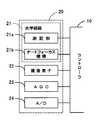
図1は、本発明の画像データ補間方法をフローチャートにより示しており、図2〜図5は、本画像データ補間方法を実施するディジタルスチルカメラの概略構成をブロック図により示している。各種の機構的および電子的な制御を行うのがコントローラ10であり、図3に示すようにその主たる構成はCPU11とROM12とRAM13とであり、これらはバス14を介して相互に接続されるとともにI/O15を介して外部の主構成部品と電気的に接続されている。
【0031】
この主構成部品の一つとして撮像部20がコントローラ10に接続されている。撮像部20については図4により詳細に示しており、光学系路21の一部として測距部21aとオートフォーカス機構21bとを備えている。本実施形態においては、測距部21aにて三角法などによって距離を測定し、オートフォーカス機構21bが測定結果に基づいて焦点合わせを行うようにしている。この場合、焦点合わせの対象となるのは予め予想された中央位置などとなる。また、撮像部20には、CCD素子からなる撮像素子22と、この撮像素子22の出力データを所定増幅率で増幅するAGC回路23と、同AGC回路23のアナログ出力値をディジタルデータに変換するA/Dコンバータ24とが備えられている。これらは個々にコントローラ10と接続されて制御されるとともに、撮像データはA/Dコンバータ24の変換データとして画像処理部30に出力されている。
【0032】
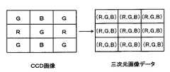
画像処理部30は光学系路21の特性であるとか撮像素子22の特性をチューニングするために備えられたハードウェア回路である。単板のCCD素子の場合には平面的に赤、緑、青の受光素子を配置せざるを得ず、縦横二次元に配列された個別の受光素子に赤緑青(RGB)のフィルタを被せて被写体画像を撮像することになる。すると、図6に示すようにある画素は緑だけ、他の画素は赤だけ、次の画素は青だけのデータしか存在しないことになってしまうため、周りの画素から他の要素色のデータを補間生成することになる。フィルタ補間回路31はこのような補間演算をハードウェアで実現するものであり、単板CCD素子からなる撮像素子22において必須となる。なお、この例では画像データは赤、緑、青の三つの構成要素からなり、さらにこれらは光の三原色であって通常の色分解によって得られる構成要素である。また、この場合の表色空間は赤、緑、青の座標軸を有していることになる。
【0033】
単板CCDにおいては各画素の受光感度のバラツキが大きくないにしてもRGBというフィルタを被せているので、自ずからその出力特性間には偏重が生じうる。自動ホワイトバランス回路32はこのような偏りを解消するものであるが、ハードウェア回路で実現するので概略的には平均的となるか特定の範囲のデータ分布が一定となるようにすることになる。また、γ補正回路33は撮像素子22の受光感度をフラットにすることが主たる役割である。
【0034】
フィルタ補間回路31についてはデータが入力されれば機械的にそのまま実行されるだけであるが、自動ホワイトバランス回路32やγ補正回路33についてはハードウェア回路で設計された補正機能に加えてコントローラ10からの具体的な指示も入力可能であり、ホワイトバランスについても意図的にシフトすることが可能であったり、γ補正回路で各要素色毎に異なるγ補正を掛けるなどして能動的な調整を可能としている。
【0035】
このような画像処理部30を経て画像データは、一旦、DRAM40に保存されるが、撮像素子22の出力イメージのままでは画像データが大きくなりすぎるため、コントローラ10は画像データをDRAM40から読み出し、符号化部70にてJPEGの圧縮フォーマットに変換させ、その後でフラッシュメモリ60に保存する。
これらの他、コントローラ10には操作表示部80が接続され、図示しないシャッターボタンなどの各種操作子と共にLCDなどの画像表示パネルも備えられている。むろん、コントローラ10は各操作子の操作状況を逐次入力しているし、撮像した画像を表示パネルに表示する。また、夜間撮影のためにストロボ90も備えられ、上記操作子で操作されたときあるいはコントローラ10によって所定の判断処理が行われたときに発光するようになっている。
【0036】
本実施形態においては、以上のようなハードウェア構成となっているが、ディジタルスチルカメラとしての構成は概略において共通するし、他の構成とすることも当然に可能である。また、この例ではディジタルスチルカメラとして実現しているが、ディジタルビデオカメラなどに組み込んで実現することも可能である。
コントローラ10は本ディジタルスチルカメラの全体的な制御を行うが、撮影時の一連の処理の流れを図7のフローチャートに示している。撮像素子22の出力データはAGC回路23に入力されて所定増幅率で増幅され、同AGC回路23のアナログ出力値はA/Dコンバータ24でディジタルデータに変換される。この時点ではまだ色フィルタの配置に起因した歯抜けのデータであるため、フィルタ補間回路31が欠陥画素を補間し、自動ホワイトバランス回路32とγ補正回路33とでRGBの出力特性間偏重を解消しつつ、受光感度をフラットにする。
【0037】
このようにしてRGBという三原色を基準としたいわゆるビットマップ形式の画像データが生成されるが、最終的に必要なのはJPEG方式の画像データであり、JPEG符号化が必要である。このJPEG符号化を行うにあたってRGB形式のままでは演算処理の負担が大きいため、この負担を低減させるためにコントローラ10内部でRGBからYUVへの表色空間の変換を行う。すなわち、三原色RGBの各色ごとに明るさで階調表現していたものを、輝度(Y)と色差(U,V)で表現し直すためにデータ形式の変換を行う。むろん、RGBの表色空間とYUVの表色空間との間では色自体が変化するものではなく、単に座標系だけが変化することになる。そして、YUVの座標系へ変換した後でJPEG符号化を行ってフラッシュメモリ60に保存する。
【0038】
この場合は最終的なデータフォーマットがJPEG方式であるが、このJPEG方式は圧縮フォーマットであるが故に画像の劣化を伴う。従って、本実施形態ではできる限り画像品質を保持できるようにJPEG符号化を行う前に画像を拡大しておき、JPEG符号化を行ったときの劣化分を低減させることにしている。
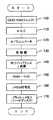
拡大は、少なくとも画素の欠陥が無くなっていて、各種の調整も終えた後であることが必要なため、実行できるのはステップ140よりも後である。従って、ステップ150においてRGBからYUVへ変換する前後で実現可能である。図8および図9は、前後のいずれかに行なうかに対応したフローチャートを示している。
【0039】
図8はRGBの画像データに対して画素補間を行う例を示し、図9はYUVの画像データに対して画素補間を行う例を示しているが、ここにおいて特徴的なのは、いずれの場合でも全ての構成要素に対して一律の補間手法を実施していない点である。
RGBの各構成要素が人間の視覚において完全に同等な感度ではないことがよく知られている。例えば、RGBのデータから簡易的に輝度Yを求める際には、Y=0.30R+0.59G+0.11B
として計算されることが多い。この計算式からも明らかなようにB成分であれば全体の明度に対して11%の寄与しかなしておらず、G成分は59%であって半分強を占めている。R成分は30%でほぼ均等割りに近いが、それでもB成分の約3倍の寄与度がある。
【0040】
これから言えるのは、B成分についての補間演算を高精度に行ったとしても画像データとして一つの画素を表す際の寄与度は極めて小さいし、逆に補間演算を簡易な演算によったとしても各画素への寄与度は小さいから画質の劣化もあまり影響しないということである。このため、RG成分についてはステップ151にて演算処理の負担が大きいものの画質をシャープにできるキュービック法を採用するし、B成分については演算処理が簡易なニアリスト法を採用している。
【0041】
ここでこれらのキュービック法の補間処理とニアリスト法の補間処理とについて説明する。各種の補間処理のうちで最もシンプルなものはニアリスト法の補間処理であり、図10に示すように周囲の四つの格子点Pij,Pi+1j,Pij+1,Pi+1j+1と内挿したい点Puvとの距離を求め、もっとも近い格子点のデータをそのまま移行させる。これを一般式で表すと、
Puv=Pij
となる。ここで、i=[u+0.5]、j=[v+0.5]である。なお、[]はガウス記号で整数部分を取ることを示している。
【0042】
ニアリスト法においては最も近い格子点を判断するものの、その格子点のデータをそのまま利用するので演算処理量が最も少ない。しかし、画像のエッジがそのまま保持される特徴を有するため、拡大すればジャギーが目立つので画質としては良好と言えない。
一方、シャープでありながらジャギーを生じさせにくい高精度な補間処理がキュービック法であり、その反面演算処理量が大きいという特徴も有している。キュービック法は図11に示すように、内挿したい点Puvを取り囲む四つの格子点のみならず、その一周り外周の格子点を含む計16の格子点のデータを利用し、3次たたみ込み関数を用いた一般式は次式のようになる。
【数1】
【数2】
【数3】
【0043】
従って、ステップ151でRG成分を高精度な補間処理で画素補間し、ステップ152でB成分について演算処理量の低い補間処理で画素補間することになる。このようにB成分について補間精度が低い補間処理を採用してはいるが、上述したようにB成分に対する人間の視覚が鈍感であるため、画質の劣化はあまり感じられず、その割には演算処理量を低減させる効果が得られるのである。
ステップ153ではRGBからYUVへのデータ変換を行うが、具体的には、上述した輝度Yを利用し、
C1=R−Y
C2=B−Y
を求めた後、
V=C1/1.14
U=C2/2.03
として、YUVの全てを演算で求める。
【0044】
一方、図9に示すように、先にステップ154にてRGBからYUVへのデータ変換を行い、その後、画素補間を行うことも可能である。この場合、ステップ155ではY成分についてのみキュービック法で画素補間し、ステップ156ではUV成分についてはニアリスト法で画素補間するようにしている。画像は白黒画像としても理解できるように、人間の視覚として輝度に対しては敏感であり、色差については比較的鈍感である。従って、色差については補間精度は低いものの演算処理の簡易なニアリスト法を採用し、最も重要な輝度についてだけ高精度な補間処理であるキュービック法を採用している。
【0045】
図8に示す順番と図9に示す順番とを比較した場合、図9に示す場合の方がキュービック法の演算処理を施す画素数が少ないことは明らかであり、その意味では後者の方が演算処理を低減させる上でより効果的である。
なお、図7に示すフローチャートと図1に示す本発明の画像データ補間方法とを対応づけると、画像データ取得工程A1はステップ100〜ステップ140までが該当するし、構成要素別画素補間工程A2はステップ150が該当するし、画像データ出力工程A3はステップ160とステップ170が該当するといえる。
【0046】
以上の処理では、RGBの座標系とLUVの座標系を利用する場合について説明したが、他の座標系であるLabやLuvやYCCなどにおいても構成要素に各座標軸を採用するようなものについても同様に適用できる。
ところで、上述したRGBからYUVへの座標変換時、輝度Yに対する色差UVの重要度の低さを予め考慮して実質的な画素密度を低減化することも多い。図13は輝度Yの画素密度と色差UVの画素密度との差を示している。画像データを構成する各画素ごとに輝度Yのデータは独立しているのに対し、色差UVのデータは左右の2画素ごとに一つのデータが割り当てられているので、データ量は同等であっても実質的な情報量は半分となっている。この意味で実質的な画素密度は均等ではない。
【0047】
上述したフィルタ補間回路31がハードウェア的にこのような変換を行う場合には、RGBからYUVへの変換であるステップ150の処理として図9に示す処理が妥当である。すなわち、ハードウェアで色差UVの画素密度が減っているのであるから、これに対して高精度な補間処理を実施したとしてもあまり意味がない。従って、ニアリスト法で画素補間することとし、それによって演算処理量の低減を図ることにする。
【0048】
また、撮像素子22は単板のCCD素子に図6に示すようなRGBのフィルタを配置して構成されていることは上述したが、欠けている画素を隣接している現実の画素に基づいて当該欠陥画素を補充しているのがフィルタ補間回路31である。しかしながら、このような補充を行うと色にじみが発生しやすい。
例えば、図14(a)において、矢印(→)で示す中段の色フィルタに着目する。そして、同図(b)に示すように中央から左半分に光が当たっており(白色部分)、同中央から右半分には光が当たっていない(黒色部分)ものとする。ここにおいて、光があたっている状態の各色の色信号レベルを「1」とし、光が当たっていない状態の同色信号レベルを「0」とすると、RおよびGの色信号レベルは、本来、同図(c)に示す値になるはずである。
【0049】
しかし、Rの色フィルタの画素についてはGの色信号は直接的には得られないし、Gの色フィルタの画素についてはRの色信号は直接的に得られず、結局、Rの色フィルタに対応する画素のGの色信号については、隣接する画素におけるGの色信号を線形補間して得ることになる。他方、Gの色フィルタに対応する画素のRの色信号についても、隣接する画素におけるRの色信号を線形補間して得る。すると、各画素におけるGおよびRの色信号レベルは、それぞれ同図(d)および(e)に示す値となる。この結果、光が当たる領域と光が当たらない領域との境界付近の画素に偽の色信号が発生し、この偽の色信号により画像上に色にじみが発生する。特に、この色にじみはグレイ・ホワイト間の境界に顕著に現れることが知られている。
【0050】
このような色にじみを低減するには、色差データに対して平滑化フィルタ(ローパスフィルタ)を作用させる画像処理を行なうと、色にじみが目立たなくなる。従って、従来は色にじみを低下させるために色差UVに対して平滑化フィルタを適用する画像処理を行なっていた。
しかしながら、このような色にじみを低減させるためという目的においても、本発明は極めて有効である。図15は色にじみを同時に低減させることが可能な画素補間処理の主要部をフローチャートにより示しており、図9に示すものと比較してY成分についてのキュービック法の補間処理に代えてステップ157にてMキュービック法の補間処理を実行し、UV成分についてのニアリスト法の補間処理に代えてステップ158にてバイリニア法の補間処理を実行するようにしている。ここで、これらのMキュービック法の補間処理とバイリニア法の補間処理について説明する。
【0051】
キュービック法では一方の格子点から他方の格子点へと近づくにつれて徐々に変化していき、その変化具合がいわゆる3次関数的になるという特徴を有している。キュービック法によれば3次関数的に表せる以上、そのカーブの形状を調整することによって補間結果の品質を左右することができる。
その調整の一例として、
【数4】
【0052】
図12には上述したキュービック法やニアリスト法とともにこのMキュービック法における補間関数f(t)を示している。同図において、横軸に位置を示し、縦軸に補間関数を示している。t=0、t=1、t=2の位置に格子点が存在し、内挿点はt=0〜1の位置となる。キュービック法とMキュービック法とを比較すると、Mキュービック法の方が3次関数的なカーブがわずかに急峻となり、画像全体のイメージがよりシャープとなる。
【0053】
次に、バイリニア法(共1次内挿法)の補間手法を説明すると、図12に示すように、一方の格子点から他方の格子点へと近づくにつれて徐々に変化していく点でキュービック法やMキュービック法と共通するが、その変化が両側の格子点のデータだけに依存する一次関数的となっている。すなわち、図10に示すように内挿したい点Puvを取り囲む四つの格子点Pij,Pi+1j,Pij+1,Pi+1j+1で区画される領域を当該内挿点Puvで四つの区画に分割し、その面積比で対角位置のデータに重み付けする。これを式で表すと、
【0054】
キュービック法とバイリニア法では、その変化状況が3次関数的であるか1次関数的であるかが異なり、画像としてみたときの差異は大きい。バイリニア法の場合、隣接する二点間(t=0〜1)で直線的に変化するだけであるので境界をスムージングすることになり、画面の印象はぼやけてしまう。これは画像に対して平滑化フィルタをかけたのと同様の効果を得られる。
図15に示すフローチャートにおいて、ステップ154ではRGBからYUVへのデータ変換を行い、ステップ157では輝度であるY成分についてMキュービック法で画素補間すると、図9に示したキュービック法の場合以上にシャープな画像が得られる。また、ステップ158では色差であるUV成分についてバイリニア法で画素補間するので、必要数の画素に拡大されつつ、平滑化フィルタをかけたのと同様になる。従って、色差自体がぼける感じとなり、色にじみは低減される。
【0055】
以上は、本発明をディジタルスチルカメラ内での画像処理に適用しているが、画素補間処理を行なう過程で構成要素ごとに補間手法を代えるのはこのような場合に限定されるわけではない。図16はこのようにして撮影された画像データに基づいてパソコンの画面に表示したり印刷したりする場合の概略のデータの流れを示している。
フラッシュメモリあるいはハードディスクに転送された画像データをステップ200にて読み出し、ステップ210にてJPEG複合化を行うと画像データはYUV形式で復元される。パソコン内ではRGB形式による処理が基本であるため、ステップ220にてYUVからRGBへデータ変換し、ステップ230にてプリンタに印字させたりディスプレイに表示したりする。
【0056】
ディスプレイに表示する場合には解像度変換を要することは多くないが、プリンタの解像度は非常に高いため、画像データの解像度を上げる必要がある。従って、この場合も先ほどと同様にしてYUVで画素補間したり、RGBで画素補間するべく、ステップ220のデータ変換時に図8や図9に示すようにして画素補間する。すると、画質を維持しつつ処理速度を高速化させることができる。
このように、RGB成分を含んでいたり、YUV成分を含んでいたりする画像データについて、その構成要素に対して一律に一つの補間処理を実行するのではなく、その構成要素ごとに補間処理を変え(ステップ151,152,155,156,157,158)、例えば、人間の視覚感度が鈍い成分については補間精度を低くして演算処理量を低減させたり、画素密度自体が低いというように情報量が減っている成分についても補間精度を低くして演算処理量を低減させることにより、画質を維持しつつ全体の演算処理量を低減させることが可能となる。
【図面の簡単な説明】
【図1】本発明の一実施形態にかかる画像データ補間方法のフローチャートである。
【図2】同画像データ補間方法を適用したディジタルスチルカメラのブロック図である。
【図3】同ディジタルスチルカメラにおけるコントローラのブロック図である。
【図4】同ディジタルスチルカメラにおける撮像部のブロック図である。
【図5】同ディジタルスチルカメラにおける画像処理部ブロック図である。
【図6】同ディジタルスチルカメラにおけるフィルタとフィルタ補間結果を示す図である。
【図7】同ディジタルスチルカメラにおける撮影時のフローチャートである。
【図8】RGB成分について構成要素別に補間処理する場合のフローチャートの一部である。
【図9】YUV成分について構成要素別に補間処理する場合のフローチャートの一部である。
【図10】基本的な画素補間で生成される画素を示す図である。
【図11】キュービック法の画素補間手法を示す図である。
【図12】画素補間で利用する補間関数の変化を示す図である。
【図13】構成要素ごとに実質的な画素密度が相違する場合を示す図である。
【図14】色フィルタの配置に基づいて色にじみが発生する状況を示す図である。
【図15】構成要素ごとに補間処理を変えつつ色にじみを低減させる場合のフローチャートの一部である。
【図16】パソコンで画像データを処理する過程を示すフローチャートである。
【符号の説明】
10…コントローラ
11…CPU
12…ROM
13…RAM
14…バス
20…撮像部
21…光学系路
21a…測距部
21b…オートフォーカス機構
22…撮像素子
23…AGC回路
24…A/Dコンバータ
30…画像処理部
31…フィルタ補完回路
32…自動ホワイトバランス回路
33…γ補正回路
40…DRAM
60…フラッシュメモリ
70…符号化部
80…操作表示部
90…ストロボ[0001]
BACKGROUND OF THE INVENTION
The present invention records an image data interpolation method, an image data interpolation device, and an image data interpolation program.Computer readable recordsIt relates to the medium.
[0002]
[Prior art]
When an image is handled by a computer or the like, the image is expressed by a dot matrix pixel, and each pixel is expressed by a gradation value. For example, photographs and computer graphics are often displayed with pixels of 640 dots in the horizontal direction and 480 dots in the vertical direction on a computer screen.
[0003]
On the other hand, the performance of color printers is remarkably improved, and the dot density is extremely high, such as 720 dpi. Then, if an image of 640 × 480 dots is printed in correspondence with each dot, the image becomes extremely small. In this case, since the gradation values are different and the meaning of the resolution itself is different, it is necessary to interpolate between dots and convert the data into printing data.
Conventionally, as a method for interpolating dots in such a case, nearest neighbor interpolation (nearlist neighbor interpolation: hereinafter referred to as the nearlist method) or cubic convolution interpolation (cubic convolution interpolation: hereinafter) A method such as a cubic method is known.
[0004]
By the way, although the near list method is simple in arithmetic processing, it cannot be said that interpolation accuracy is high in terms of image quality. On the other hand, the cubic method seems to be good because the interpolation accuracy is high in terms of image quality, but the processing load is heavy. Therefore, conventionally, the near list method or the cubic method is determined depending on whether or not it may take time. Further, the selection is left to the user, and the cubic method can be selected on the premise that it takes time when a good image quality is desired.
[0005]
[Problems to be solved by the invention]
In the above-described conventional method, the near list method or the cubic method is switched depending on whether the processing speed is important or the image quality is important. However, the user desires faster processing without degrading the image quality. It was. The present invention has been made in view of the above problems, and has recorded an image data interpolation method, an image data interpolation device, and an image data interpolation program capable of realizing pixel interpolation at a higher speed without degrading image quality.Computer readable recordsThe purpose is to provide a medium.
[0006]
[Means for Solving the Problems]
In order to achieve the above object, the invention according to claim 1An image data interpolation method for performing interpolation processing of image data using a computer having a calculation means, wherein the calculation meansConfigure an imageA gradation value indicating the degree of each component including at least a luminance component and a color difference component.An image data acquisition step of acquiring the image data that has been represented;The calculation means sharpens the image with respect to the luminance component, and executes a first interpolation process having higher interpolation accuracy than the interpolation process performed with respect to the color difference component, and the color difference component with respect to the first interpolation process. The second that blurs the image with high interpolation speed.A component-specific pixel interpolation process for performing interpolation processing;By the above calculation means,An image data output process for outputting the interpolated image data;IncludeAs a configuration.
[0007]
In the invention according to
[0008]
That is, one interpolation process is not executed uniformly for each component of the image data, but the interpolation process is changed for each component. This is because it is not always proportional to the image quality to make the interpolation process highly accurate for each component. Therefore, calculation processing is simplified for components that do not contribute much to image quality when interpolation processing with high accuracy is performed, and the load of calculation processing for components that have a sensitive influence on image quality is difficult. It is reasonable to combine large but highly accurate interpolation processes.
[0009]
Since the one-dimensional representation of image data is inconvenient, multidimensional representation is preferable, and the color space is represented by multidimensional representation. Therefore, in such a color space, there are a series of relationships between the coordinate axes, and the correspondence between the burden and effect of the interpolation processing is often different for each coordinate axis. For this reason, an optimum result can be derived by changing the interpolation processing with reference to the coordinate axis.
[0010]
The color space is represented by a plurality of separated element colors. Here, human visual sensitivity for each element color is often different. For example, in the case of R (red), G (green), and B (blue) expressed as the three primary colors of light, human visual sensitivity to blue is low. Therefore, even if a simple calculation process is executed for the blue component, the interpolation result does not deteriorate much. That is, paying attention to the difference in human visual sensitivity for each element color, associating high-precision interpolation processing with sensitive element colors, and associating low-precision interpolation processing with insensitive element colors, The total amount of calculation processing is reduced without causing deterioration in image quality.
[0011]
The color space has a luminance component coordinate axis and a color difference component coordinate axis. In this case, in the pixel interpolation process for each component, the component of the color difference component is executed when the interpolation process is performed on the component of the luminance component. The interpolation accuracy is made higher than the interpolation processing executed for.
[0012]
For example, as is clear from the example of television broadcasting, the luminance signal is absolutely larger than the color difference signal as the amount of information. In other words, the frequency band required for modulating the luminance signal is the same as the frequency band required for modulating the color difference signal. Thus, since the original information amount is biased between luminance and color difference, interpolation processing with high interpolation accuracy that requires arithmetic processing for luminance with a large amount of information is executed, and much arithmetic processing is required for color difference with small information amount. Do not perform interpolation processing with low interpolation accuracy.Here, an interpolation process for blurring pixels is associated as an interpolation process that does not impose a heavy processing load on color differences. As a result, while achieving the original purpose of interpolation, an effect of reducing blur is produced in conjunction with this.
[0015]
On the other hand, the process of acquiring image data is not limited to inputting the prepared image data as it is, but may include a process of generating image data or a process of processing. Therefore, when the processing as a whole is required, conversion of the color space may be necessary.2According to the invention, in the image data interpolation method according to
[0016]
In the light of the previous example, there was no difference in importance between components in the first image data, but the color space required in the subsequent process requires components of luminance and color difference. In this case, the degree of importance varies among the components, and the present invention can be suitably applied when such conversion is necessary. Therefore, the claims2In the invention according to the present invention, the color space of the input image data is converted when the image data acquisition step is performed, and the image data subjected to the pixel interpolation processing as described above is output. In the process, image data subjected to pixel interpolation processing at high speed can be obtained without deterioration in image quality.
[0017]
By the way, as an example in which the image data acquisition step includes a step of capturing an image, it may be applied to an imaging device such as a digital still camera. In the case of a digital still camera, shooting is performed with a solid-state image sensor, but a single-plate solid-state image sensor expresses three colors of RGB while arranging the photosensitive elements in a dot matrix form. Allocate colors and use them. Therefore, if the photosensitive elements are arranged like a grid on the grid, each of RGB is allocated in a missing state, and in actuality, when outputting as image data while receiving light in such a missing state. Data of missing pixels is calculated by calculation so that each of RGB has data in all grids of the grid.
[0018]
When pixel data is replenished in this way, it is known that bleeding occurs in image data because the density is not uniform for each element color. In order to solve this problem, a process of blurring an image, particularly a color difference is useful. Therefore, an image process of blurring the image to remove the blur is separately performed.
[0020]
Similarly, the process of outputting the image data is not limited to passing the pixel-interpolated image data to the subsequent process, but also a process of printing out the image data or a process of converting the data format, etc. May be included. In such a case, assuming that the components of the image data required in the subsequent process are biased as described above, the original amount of information may be reduced simply by converting the color space. Absent. That is, it is unfortunate that this is the case even though the image data has a large amount of information. As an example suitable for such a case, the claims3According to another aspect of the invention, in the image data interpolation method according to any one of
[0021]
Claims configured as above3In the invention according to the present invention, the image density is improved in the pixel interpolation process for each component that can maintain high image quality without placing a heavy burden on the arithmetic processing in advance, and the image accuracy that degrades the information accuracy in the image data output process. Perform data format conversion. In this way, it seems that only the format conversion of the image data is performed after increasing the image density, but it can be said that the drop of information is reduced when data is allocated to a component having a small amount of information. Although it is a data format that substantially degrades the amount of information, the image density is high, so it can be said that the information amount close to the previous data format is maintained as a whole when both are offset Because.
[0022]
In this way, a method of changing the interpolation process for each component instead of performing a single interpolation process for each component of the image data is realized in a substantial apparatus, and the present invention is It can be easily understood that the present invention can also be applied as an apparatus having a certain size. For this reason, the claim6The invention according to the invention constitutes an imageA gradation value indicating the degree of each component including at least a luminance component and a color difference component.Image data acquisition means for acquiring image data for acquiring image data to be represented;The calculation means sharpens the image with respect to the luminance component, and executes a first interpolation process having higher interpolation accuracy than the interpolation process performed with respect to the color difference component, and the color difference component with respect to the first interpolation process. The second that blurs the image with high interpolation speed.A pixel interpolating means for each component for executing the interpolation processing, and an image data output means for outputting the interpolated image data.HaveAs a configuration.
[0023]
That is, there is no difference in that it is effective as a substantial device. Such an image data interpolating apparatus may be implemented independently, or may be implemented together with other methods in a state where the apparatus is incorporated in a certain device. Including embodiments. Therefore, it can be changed as appropriate, such as software or hardware. In the case of software that implements the image data interpolation method as an embodiment of the idea of the invention, it naturally exists on a recording medium that records such software, and it must be used.
[0024]
As an example, the claims7The invention according toIn the computer having the calculation means, by the calculation means,Configure an imageA gradation value indicating the degree of each component including at least a luminance component and a color difference component.Image data to representTo getAn image data acquisition step;The calculation means sharpens the image with respect to the luminance component, and executes a first interpolation process having higher interpolation accuracy than the interpolation process performed with respect to the color difference component, and the color difference component with respect to the first interpolation process. The second that blurs the image with high interpolation speed.A component-specific pixel interpolation step for performing interpolation processing;By the above calculation means,An image data output step for outputting the interpolated image data;Computer-readable recording medium on which a pixel interpolation program for executingIt is as.
[0025]
Of course, the recording medium may be a magnetic recording medium, a magneto-optical recording medium, or any recording medium that will be developed in the future. In addition, the duplication stages such as the primary duplication product and the secondary duplication product are equivalent without any question. In addition, even when the communication method is used as a supply method, the present invention is not changed.
Further, even when a part is software and a part is realized by hardware, the idea of the invention is not completely different, and a part is stored on a recording medium and is appropriately changed as necessary. It may be in the form of being read.
[0026]
【The invention's effect】
As described above, the present invention can provide an image data interpolation method capable of realizing pixel interpolation at higher speed without degrading image quality.
[0030]
DETAILED DESCRIPTION OF THE INVENTION
FIG. 1 is a flowchart showing an image data interpolation method of the present invention, and FIGS. 2 to 5 are block diagrams showing a schematic configuration of a digital still camera that implements the image data interpolation method. The
[0031]
The
[0032]
The
[0033]
Since the single-plate CCD is covered with a filter called RGB even if the variation in the light receiving sensitivity of each pixel is not large, the output characteristics may naturally deviate. The automatic
[0034]
The
[0035]
The image data is temporarily stored in the
In addition to these, an
[0036]
In the present embodiment, the hardware configuration is as described above. However, the configuration as a digital still camera is generally the same, and other configurations are naturally possible. In this example, it is realized as a digital still camera, but it can also be realized by being incorporated in a digital video camera or the like.
The
[0037]
In this way, image data in a so-called bitmap format based on the three primary colors of RGB is generated, but what is ultimately required is JPEG image data, which requires JPEG encoding. In performing the JPEG encoding, if the RGB format is used as it is, the processing load is large. Therefore, in order to reduce this load, the color space of RGB to YUV is converted inside the
[0038]
In this case, the final data format is the JPEG method, but this JPEG method is a compression format, and therefore involves image degradation. Therefore, in the present embodiment, an image is enlarged before JPEG encoding so that the image quality can be maintained as much as possible, and the deterioration when JPEG encoding is performed is reduced.
Since the enlargement needs to be at least after pixel defects have been eliminated and various adjustments have been completed, the enlargement can be performed after
[0039]
FIG. 8 shows an example in which pixel interpolation is performed on RGB image data, and FIG. 9 shows an example in which pixel interpolation is performed on YUV image data. The point is that no uniform interpolation method is applied to these components.
It is well known that the RGB components are not completely equivalent in human vision. For example, when simply obtaining the luminance Y from RGB data, Y = 0.30R + 0.59G + 0.11B
Is often calculated as As is clear from this calculation formula, the B component only contributes 11% to the overall brightness, and the G component is 59%, accounting for more than half. The R component is nearly equal at 30%, but still contributes about three times as much as the B component.
[0040]
It can be said from this that even if the interpolation calculation for the B component is performed with high accuracy, the degree of contribution when representing one pixel as image data is extremely small. Since the contribution to the pixel is small, the deterioration of the image quality is not so much affected. For this reason, for the RG component, the cubic method that can sharpen the image quality is adopted in
[0041]
Here, the interpolation process of the cubic method and the interpolation process of the near list method will be described. The simplest of the various interpolation processes is an interpolation process of the near list method, and as shown in FIG. The data of the nearest grid point is obtained and transferred as it is. This can be expressed as a general formula:
Puv = Pij
It becomes. Here, i = [u + 0.5] and j = [v + 0.5]. In addition, [] has shown taking an integer part with a Gauss symbol.
[0042]
In the near list method, the nearest grid point is determined, but the data of the grid point is used as it is, so that the calculation processing amount is the smallest. However, since the edge of the image is maintained as it is, jaggies become conspicuous if it is enlarged, so it cannot be said that the image quality is good.
On the other hand, high-accuracy interpolation processing that is sharp but does not easily cause jaggies is the cubic method, and has a feature that the amount of calculation processing is large. As shown in FIG. 11, the cubic method uses the data of a total of 16 lattice points including not only four lattice points surrounding the point Puv to be interpolated but also surrounding lattice points, and a cubic convolution function. The general formula using is as follows.
[Expression 1]
[Expression 2]
[Equation 3]
[0043]
Therefore, pixel interpolation is performed for the RG component with high-precision interpolation processing at
In
C1 = R−Y
C2 = BY
After asking
V = C1 / 1.14
U = C2 / 2.03
As a result, all of YUV are obtained by calculation.
[0044]
On the other hand, as shown in FIG. 9, it is also possible to perform data conversion from RGB to YUV first in
[0045]
When the order shown in FIG. 8 and the order shown in FIG. 9 are compared, it is clear that the number of pixels subjected to the arithmetic processing of the cubic method is smaller in the case shown in FIG. It is more effective in reducing processing.
If the flowchart shown in FIG. 7 is associated with the image data interpolation method of the present invention shown in FIG. 1, the image data acquisition step A1 corresponds to step 100 to step 140, and the component-specific pixel interpolation
[0046]
In the above processing, the case where the RGB coordinate system and the LUV coordinate system are used has been described. However, in other coordinate systems such as Lab, Luv, and YCC, each coordinate axis is adopted as a component. The same applies.
By the way, in the above-described coordinate conversion from RGB to YUV, the substantial pixel density is often reduced in consideration of the low importance of the color difference UV with respect to the luminance Y in advance. FIG. 13 shows the difference between the pixel density of luminance Y and the pixel density of color difference UV. The luminance Y data is independent for each pixel constituting the image data, whereas the color difference UV data is assigned to one pixel for each of the two left and right pixels, so the data amount is the same. However, the actual amount of information is halved. In this sense, the substantial pixel density is not uniform.
[0047]
When the above-described
[0048]
Further, as described above, the
For example, in FIG. 14A, attention is focused on the middle color filter indicated by an arrow (→). Then, as shown in FIG. 5B, it is assumed that the left half of the center is exposed to light (white portion) and the right half of the center is not exposed to light (black portion). Here, assuming that the color signal level of each color in a state where light is shining is “1” and the same color signal level in a state where no light is shining is “0”, the color signal levels of R and G are essentially the same. The value should be as shown in FIG.
[0049]
However, the G color signal cannot be obtained directly for the R color filter pixels, and the R color signal cannot be obtained directly for the G color filter pixels. The G color signal of the corresponding pixel is obtained by linear interpolation of the G color signal of the adjacent pixel. On the other hand, the R color signal of the pixel corresponding to the G color filter is also obtained by linear interpolation of the R color signal of the adjacent pixel. Then, the G and R color signal levels in each pixel are the values shown in FIGS. As a result, a false color signal is generated in a pixel near the boundary between the area that is exposed to light and the area that is not exposed to light, and the color blur is generated on the image due to the false color signal. In particular, it is known that this color blur appears prominently at the boundary between gray and white.
[0050]
In order to reduce such color blurring, color blurring becomes inconspicuous when image processing for applying a smoothing filter (low-pass filter) to color difference data is performed. Therefore, conventionally, image processing for applying a smoothing filter to the color difference UV has been performed in order to reduce color bleeding.
However, the present invention is extremely effective for the purpose of reducing such color blur. FIG. 15 is a flowchart showing the main part of the pixel interpolation process capable of simultaneously reducing the color blur. Compared with the one shown in FIG. 9, the interpolation process of the cubic method for the Y component is replaced with
[0051]
The cubic method has a feature that it gradually changes as it approaches from one lattice point to the other lattice point, and the degree of change becomes a so-called cubic function. Since the cubic method can be expressed in a cubic function, the quality of the interpolation result can be influenced by adjusting the shape of the curve.
As an example of the adjustment,
[Expression 4]
[0052]
FIG. 12 shows the interpolation function f (t) in the M cubic method together with the above-described cubic method and near list method. In the figure, the horizontal axis indicates the position, and the vertical axis indicates the interpolation function. There are lattice points at the positions of t = 0, t = 1, and t = 2, and the interpolation point is at the position of t = 0 to 1. When the cubic method and the M cubic method are compared, the cubic function curve is slightly steeper in the M cubic method, and the entire image becomes sharper.
[0053]
Next, the bilinear method (bilinear interpolation method) interpolation method will be described. As shown in FIG. 12, the cubic method is such that it gradually changes from one lattice point to the other lattice point. In common with the M cubic method, the change is a linear function that depends only on the data of the lattice points on both sides. That is, as shown in FIG. 10, an area defined by four grid points Pij, Pi + 1j, Pij + 1, and Pi + 1j + 1 surrounding a point Puv to be interpolated is divided into four sections at the interpolation point Puv, and the area ratio is compared. Weight the corner position data. This can be expressed as an expression:
[0054]
The cubic method and the bilinear method differ in whether the change state is a cubic function or a linear function, and the difference when viewed as an image is large. In the case of the bilinear method, since it changes only linearly between two adjacent points (t = 0 to 1), the boundary is smoothed, and the impression of the screen is blurred. This can obtain the same effect as a smoothing filter applied to the image.
In the flowchart shown in FIG. 15, in
[0055]
In the above, the present invention is applied to image processing in a digital still camera, but changing the interpolation method for each component in the process of performing pixel interpolation processing is not limited to such a case. FIG. 16 shows a schematic data flow when displaying or printing on the screen of a personal computer based on the image data thus taken.
When the image data transferred to the flash memory or the hard disk is read at
[0056]
When displaying on a display, it is not often necessary to convert the resolution, but since the resolution of the printer is very high, it is necessary to increase the resolution of the image data. Therefore, in this case as well, pixel interpolation is performed as shown in FIGS. 8 and 9 at the time of data conversion in
In this way, for image data including RGB components or YUV components, instead of performing a single interpolation process uniformly on the constituent elements, the interpolation processing is changed for each constituent element. (
[Brief description of the drawings]
FIG. 1 is a flowchart of an image data interpolation method according to an embodiment of the present invention.
FIG. 2 is a block diagram of a digital still camera to which the image data interpolation method is applied.
FIG. 3 is a block diagram of a controller in the digital still camera.
FIG. 4 is a block diagram of an imaging unit in the digital still camera.
FIG. 5 is a block diagram of an image processing unit in the digital still camera.
FIG. 6 is a diagram illustrating filters and filter interpolation results in the digital still camera.
FIG. 7 is a flowchart at the time of shooting in the digital still camera.
FIG. 8 is a part of a flowchart in the case of interpolating RGB components for each component.
FIG. 9 is a part of a flowchart in the case of performing interpolation processing for each component of YUV components.
FIG. 10 is a diagram illustrating pixels generated by basic pixel interpolation.
FIG. 11 is a diagram illustrating a pixel interpolation method of a cubic method.
FIG. 12 is a diagram illustrating a change in an interpolation function used in pixel interpolation.
FIG. 13 is a diagram illustrating a case where a substantial pixel density is different for each component.
FIG. 14 is a diagram illustrating a situation in which color bleeding occurs based on the arrangement of color filters.
FIG. 15 is a part of a flowchart in a case where color blur is reduced while changing interpolation processing for each component.
FIG. 16 is a flowchart showing a process of processing image data on a personal computer.
[Explanation of symbols]
10 ... Controller
11 ... CPU
12 ... ROM
13 ... RAM
14 ... Bus
20 ... Imaging unit
21 ... Optical path
21a: Distance measuring unit
21b ... autofocus mechanism
22: Image sensor
23 ... AGC circuit
24 ... A / D converter
30. Image processing unit
31 ... Filter complementation circuit
32 ... Automatic white balance circuit
33 ... γ correction circuit
40 ... DRAM
60: Flash memory
70: Encoding unit
80 ... Operation display section
90 ... Strobe
Claims (7)
Translated fromJapanese上記演算手段により、画像を構成する複数の画素を少なくとも輝度成分と色差成分を含む各構成要素についての程度を示す階調値で表すようにした画像データを取得する画像データ取得工程と、
上記演算手段により、上記輝度成分について上記画像をシャープにさせるとともに上記色差成分について実行する補間処理よりも補間精度が高い第1の補間処理を実行し、上記色差成分について上記第1の補間処理より補間速度が速く上記画像をぼやけさせる第2の補間処理を実行する構成要素別画素補間工程と、
上記演算手段により、補間された画像データを出力する画像データ出力工程とを含むことを特徴とする画像データ補間方法。An image data interpolation method for performing image data interpolation processing using a computer having arithmetic means,
An image data acquisition step of acquiring image data in which aplurality of pixels constituting the image are represented bygradation values indicating the degree of each component including at least a luminance component and a color difference componentby the arithmetic means ;
The calculation means sharpens the image with respect to the luminance component, and executes a first interpolation process having higher interpolation accuracy than the interpolation process performed with respect to the color difference component, and the color difference component with respect to the first interpolation process. A pixel-by-component interpolation process for executing asecond interpolation process thatblurs the image with a high interpolation speed ;
An image data interpolation methodcomprising: an image data output step of outputting image data interpolated by thearithmetic means .
上記演算手段により、上記輝度成分について上記画像をシャープにさせるとともに上記色差成分について実行する補間処理よりも補間精度が高い第1の補間処理を実行し、上記色差成分について上記第1の補間処理より補間速度が速く上記画像をぼやけさせる第2の補間処理を実行する構成要素別画素補間手段と、
補間された画像データを出力する画像データ出力手段とを有することを特徴とする画像データ補間装置。Image data acquisition means for acquiring image data for acquiring image data in which aplurality of pixels constituting an image are represented bygradation values indicating the degree of each component including at least a luminance component and a color difference component ;
The calculation means sharpens the image with respect to the luminance component, and executes a first interpolation process having higher interpolation accuracy than the interpolation process performed with respect to the color difference component, and the color difference component with respect to the first interpolation process. A pixel-by-component interpolating unit that executes asecond interpolation process thatblurs the image at a high interpolation speed ;
Image data interpolating apparatus characterized byhaving an image data output means for outputting the interpolated image data.
上記演算手段により、画像を構成する複数の画素を少なくとも輝度成分と色差成分を含む各構成要素についての程度を示す階調値で表すようにした画像データを取得する画像データ取得ステップと、
上記演算手段により、上記輝度成分について上記画像をシャープにさせるとともに上記色差成分について実行する補間処理よりも補間精度が高い第1の補間処理を実行し、上記色差成分について上記第1の補間処理より補間速度が速く上記画像をぼやけさせる第2の補間処理を実行する構成要素別画素補間ステップと、
上記演算手段により、補間された画像データを出力する画像データ出力ステップとを実行させるための画素補間プログラムを記録したコンピュータ読み取り可能な記録媒体。In a computer having a computing means,
An image data acquisition step ofacquiring image data inwhich aplurality of pixels constituting the image are represented bygradation values indicating the degree of each component including at least a luminance component and a color difference componentby the arithmetic means ;
The calculation means sharpens the image with respect to the luminance component, and executes a first interpolation process having higher interpolation accuracy than the interpolation process performed with respect to the color difference component, and the color difference component with respect to the first interpolation process. A pixel-by-component interpolation step for performing asecond interpolation process thatblurs the image with a high interpolation speed ;
A computer-readable recording medium recording a pixel interpolation program for executing an image data output step of outputting image data interpolated by thearithmetic means.
Priority Applications (1)
| Application Number | Priority Date | Filing Date | Title |
|---|---|---|---|
| JP31645598AJP4032200B2 (en) | 1998-11-06 | 1998-11-06 | Image data interpolation method, image data interpolation device, and computer readable recording medium recording image data interpolation program |
Applications Claiming Priority (1)
| Application Number | Priority Date | Filing Date | Title |
|---|---|---|---|
| JP31645598AJP4032200B2 (en) | 1998-11-06 | 1998-11-06 | Image data interpolation method, image data interpolation device, and computer readable recording medium recording image data interpolation program |
Publications (3)
| Publication Number | Publication Date |
|---|---|
| JP2000151989A JP2000151989A (en) | 2000-05-30 |
| JP2000151989A5 JP2000151989A5 (en) | 2006-02-02 |
| JP4032200B2true JP4032200B2 (en) | 2008-01-16 |
Family
ID=18077292
Family Applications (1)
| Application Number | Title | Priority Date | Filing Date |
|---|---|---|---|
| JP31645598AExpired - Fee RelatedJP4032200B2 (en) | 1998-11-06 | 1998-11-06 | Image data interpolation method, image data interpolation device, and computer readable recording medium recording image data interpolation program |
Country Status (1)
| Country | Link |
|---|---|
| JP (1) | JP4032200B2 (en) |
Families Citing this family (5)
| Publication number | Priority date | Publication date | Assignee | Title |
|---|---|---|---|---|
| JP4225795B2 (en) | 2003-01-22 | 2009-02-18 | オリンパス株式会社 | Imaging system, image processing program |
| KR100769193B1 (en)* | 2006-02-06 | 2007-10-23 | 엘지.필립스 엘시디 주식회사 | Flat panel display and image quality control method and device |
| JP4693649B2 (en)* | 2006-02-17 | 2011-06-01 | シャープ株式会社 | Image processing apparatus and image data interpolation method |
| JP5098054B2 (en) | 2007-11-22 | 2012-12-12 | オリンパス株式会社 | Image processing apparatus and image processing program |
| CN111526370B (en)* | 2020-04-17 | 2023-06-02 | Oppo广东移动通信有限公司 | Video encoding and decoding methods and devices and electronic equipment |
- 1998
- 1998-11-06JPJP31645598Apatent/JP4032200B2/ennot_activeExpired - Fee Related
Also Published As
| Publication number | Publication date |
|---|---|
| JP2000151989A (en) | 2000-05-30 |
Similar Documents
| Publication | Publication Date | Title |
|---|---|---|
| JP4081219B2 (en) | Image processing method and image processing apparatus | |
| US20020176113A1 (en) | Dynamic image correction and imaging systems | |
| JP3668014B2 (en) | Image processing method and apparatus | |
| JPH0355078B2 (en) | ||
| JP2002262094A (en) | Image processing method and image processor | |
| JP4600424B2 (en) | Development processing apparatus for undeveloped image data, development processing method, and computer program for development processing | |
| JP7296745B2 (en) | Image processing device, image processing method, and program | |
| JP5136209B2 (en) | Development processing apparatus for undeveloped image data, development processing method, and computer program for development processing | |
| JP2007096509A (en) | Image processing apparatus and image processing method | |
| JP3913356B2 (en) | Image processing method | |
| JP3998369B2 (en) | Image processing method and image processing apparatus | |
| US20010016081A1 (en) | Image filter circuit | |
| JP2021140663A (en) | Image processing methods, image processing devices, image processing programs, and storage media | |
| JP4032200B2 (en) | Image data interpolation method, image data interpolation device, and computer readable recording medium recording image data interpolation program | |
| JP5070921B2 (en) | Development processing apparatus for undeveloped image data, development processing method, and computer program for development processing | |
| JP3783817B2 (en) | Image processing method and image processing apparatus | |
| JP2008219230A (en) | Imaging apparatus, and image processing method | |
| JP3951993B2 (en) | IMAGING DEVICE AND COLOR DATA MEASURING METHOD USED FOR THIS IMAGING DEVICE | |
| JPH11225270A (en) | Image processing method and image processor | |
| JP5109804B2 (en) | Development processing apparatus for undeveloped image data, development processing method, and computer program for development processing | |
| JP2011041094A (en) | Image processing apparatus, imaging apparatus, and method of processing image | |
| JP2011041094A5 (en) | ||
| JP4807315B2 (en) | Development processing apparatus for undeveloped image data, development processing method, and computer program for executing development processing | |
| JP2002051225A (en) | Device and method for processing image | |
| JP3625370B2 (en) | Image processing method and image processing apparatus |
Legal Events
| Date | Code | Title | Description |
|---|---|---|---|
| A521 | Request for written amendment filed | Free format text:JAPANESE INTERMEDIATE CODE: A523 Effective date:20051102 | |
| A621 | Written request for application examination | Free format text:JAPANESE INTERMEDIATE CODE: A621 Effective date:20051102 | |
| A977 | Report on retrieval | Free format text:JAPANESE INTERMEDIATE CODE: A971007 Effective date:20070427 | |
| A131 | Notification of reasons for refusal | Free format text:JAPANESE INTERMEDIATE CODE: A131 Effective date:20070509 | |
| A521 | Request for written amendment filed | Free format text:JAPANESE INTERMEDIATE CODE: A523 Effective date:20070709 | |
| TRDD | Decision of grant or rejection written | ||
| A01 | Written decision to grant a patent or to grant a registration (utility model) | Free format text:JAPANESE INTERMEDIATE CODE: A01 Effective date:20070926 | |
| A61 | First payment of annual fees (during grant procedure) | Free format text:JAPANESE INTERMEDIATE CODE: A61 Effective date:20071009 | |
| FPAY | Renewal fee payment (event date is renewal date of database) | Free format text:PAYMENT UNTIL: 20101102 Year of fee payment:3 | |
| R150 | Certificate of patent or registration of utility model | Free format text:JAPANESE INTERMEDIATE CODE: R150 | |
| FPAY | Renewal fee payment (event date is renewal date of database) | Free format text:PAYMENT UNTIL: 20101102 Year of fee payment:3 | |
| FPAY | Renewal fee payment (event date is renewal date of database) | Free format text:PAYMENT UNTIL: 20111102 Year of fee payment:4 | |
| FPAY | Renewal fee payment (event date is renewal date of database) | Free format text:PAYMENT UNTIL: 20111102 Year of fee payment:4 | |
| FPAY | Renewal fee payment (event date is renewal date of database) | Free format text:PAYMENT UNTIL: 20121102 Year of fee payment:5 | |
| FPAY | Renewal fee payment (event date is renewal date of database) | Free format text:PAYMENT UNTIL: 20121102 Year of fee payment:5 | |
| FPAY | Renewal fee payment (event date is renewal date of database) | Free format text:PAYMENT UNTIL: 20131102 Year of fee payment:6 | |
| S531 | Written request for registration of change of domicile | Free format text:JAPANESE INTERMEDIATE CODE: R313531 | |
| R350 | Written notification of registration of transfer | Free format text:JAPANESE INTERMEDIATE CODE: R350 | |
| LAPS | Cancellation because of no payment of annual fees |