JP4031260B2 - Solid matter sterilization method and sterilizer - Google Patents
Solid matter sterilization method and sterilizerDownload PDFInfo
- Publication number
- JP4031260B2 JP4031260B2JP2002046872AJP2002046872AJP4031260B2JP 4031260 B2JP4031260 B2JP 4031260B2JP 2002046872 AJP2002046872 AJP 2002046872AJP 2002046872 AJP2002046872 AJP 2002046872AJP 4031260 B2JP4031260 B2JP 4031260B2
- Authority
- JP
- Japan
- Prior art keywords
- sterilization
- pressure vessel
- pressure
- carry
- region
- Prior art date
- Legal status (The legal status is an assumption and is not a legal conclusion. Google has not performed a legal analysis and makes no representation as to the accuracy of the status listed.)
- Expired - Fee Related
Links
Images


Landscapes
- Apparatus For Disinfection Or Sterilisation (AREA)
- Food Preservation Except Freezing, Refrigeration, And Drying (AREA)
Description
Translated fromJapanese【0001】
【発明の属する技術分野】
本発明は、容器に収容された調理済食品に含まれる固形物を蒸気等の熱媒と直接接触させて殺菌する方法及び装置に関する。
【0002】
【従来の技術】
調理済食品の殺菌方法としては、従来より調理済食品を袋詰めして密封した後、その袋をレトルト釜に収容して高温に加熱することにより、内容物を殺菌する間接加熱殺菌法が使用されていた。しかし、袋を介した間接殺菌法においては、液体成分も固形物も同一条件で加熱される、液体成分の熱伝導によって徐々に固形物の中心まで殺菌するため、殺菌時間が長くなり、固形物と液体成分がともに過加熱状態となって風味が損なわれる、等の問題がある。
【0003】
そこで、固形物を直接蒸気と接触させて加熱殺菌する直接加熱殺菌法が種々提案され、実施されている。直接加熱殺菌方法による固形物の殺菌においては、殺菌前に固形物が計量されて所定量ずつ小分けされ、分けられた固形物がカップに収容される。各カップは同一の殺菌釜(圧力容器に相当)に収容される。殺菌釜の密閉後、その内部は真空吸引され、その後に殺菌釜内に蒸気が導入される。蒸気による加熱が所定時間継続された後、真空冷却が行われ、その後に各カップが殺菌釜から取り出される。こうした直接加熱殺菌方法によれば、固形物を蒸気と直接接触させているので、固形物に適した殺菌条件が設定でき、加熱処理が短時間で完了して固形物の風味が損なわれない、殺菌前に計量して包装単位量ずつの小分けを済ませるので、殺菌後に固形物を計量して小分けを行う場合と比較して、個食化に容易に対応できる等の利点がある。
【0004】
【発明が解決しようとする課題】
ところが、これまでの直接加熱殺菌方法は、大量のカップを同一の殺菌釜に収容して一度に処理するいわゆるバッチ処理である。従って、処理能力を上げようとすれば殺菌釜を大型化する必要があり、装置の設置面積が嵩む。殺菌処理後には大量のカップを一度に取り出す必要があり、かつその作業も無菌環境で行う必要があるため、殺菌釜の出口側に広大な無菌アキューム領域を確保する必要があり、設備がさらに大規模化する。殺菌後の大量のカップを殺菌釜から無菌アキューム領域へ一度に取り出し、その後に各カップから順次固形物を取り出して後工程へ送り出す処理を行うと、各カップの固形物が無菌アキューム領域に保持される時間が処理の前後によって大きく相違する。無菌アキューム領域は無菌エアが絶えず供給されて陽圧に維持されているため、その内部に保持される時間が長いほど固形物の乾燥が進行し、品質にばらつきが生じる。
【0005】
こうした欠点を解消するために、例えば特許第2907763号公報の殺菌装置では、複数の殺菌機を並べておき、所定数のカップを収容したカセットを各殺菌機に選択的に投入することにより、複数の殺菌機で並行してバッチ処理を行って連続的に固形物を取り出している。しかし、複数の殺菌機の出口側をすべて無菌アキューム領域に収容する必要があり、無菌アキューム領域がやはり大きくなる。
【0006】
特許第2815089号公報には、工程毎に複数の処理室に仕切った殺菌処理槽を用意し、固形物を収容したカップを各処理室に順次送ることにより、単一の処理槽で連続的に殺菌を行う装置が提案されている。しかし、このように単一の処理槽の内部を複数の処理室に気密に区切ることは難しく、かつ処理槽の内部は真空や高温環境に曝されるので処理槽内でカップを搬送することが難しい。そのため、当該公報の装置においても処理槽そのものをシーソー状に揺動させてカップを搬送するものとしているが、現実問題としてこうした機構を実用化することは困難が伴う。
【0007】
本発明は上記の事情に鑑みてなされたものであり、従来とは異なる構成により固形物を所定量ずつ連続的に処理可能な殺菌方法及び殺菌装置を提供することを目的とする。
【0008】
【課題を解決するための手段】
以下、本発明の殺菌方法及び殺菌装置について説明する。なお、本発明の理解を容易にするために添付図面の参照符号を括弧書きにて付記するが、それにより本発明が図示の形態に限定されるものではない。
【0009】
本発明の殺菌方法は、 複数の圧力容器(3)のそれぞれを、所定の循環経路に設定された搬入部(12)にて搬送機構上に搬送しつつ前記搬送機構の駆動装置を駆動することにより、各圧力容器を前記循環経路に沿って無菌領域(Z1)内の搬出部(13)へと順次移動させ、前記搬入部では、所定量の固形物(10)が収容された複数の保持具(8)を各圧力容器に挿入して該圧力容器を個別に密閉し、前記搬入部から前記搬出部へと移動中の各圧力容器の内部では、固形物を殺菌するための処理を実行し、前記搬出部では各圧力容器を開放して保持具及び固形物を圧力容器から取り出し、前記搬送機構の前記駆動装置の駆動を利用して、空の圧力容器を前記搬出部から前記搬入部へと前記循環経路に沿って返送する、ことを特徴とする。
【0010】
この殺菌方法によれば、圧力容器を順次搬送しつつ殺菌を行うので、圧力容器に収容する保持具の個数を例えば数個以内に制限し、その制限と引き替えに圧力容器の個数を増加させることにより、各圧力容器における殺菌処理そのものはバッチ式であっても、全体としては、固形物を少量ずつ順に殺菌して連続的な処理を実現することができる。搬出部には、殺菌処理が完了した圧力容器が順に送り込まれるようになり、搬出部にて一度に大量の保持具を処理する必要がなくなる。このため、広大な無菌アキューム領域は不要となる。さらに、一つ一つの圧力容器が小型化されることにより、これらを容易に搬送することができる。しかも、圧力容器内にて保持具を搬送する必要がない。従って、装置が簡素化される。
【0011】
本発明の殺菌方法においては、前記無菌領域の手前に外面殺菌領域(Z2)を区画し、当該外面殺菌領域に導入された圧力容器に対して外面殺菌処理を行うことが望ましい。これによれば、無菌領域に取り込まれる前に圧力容器の外面が殺菌される。従って、搬入部から外面殺菌領域に至る部分を、無菌処理された環境に設置する必要がなくなる。さらに、外面殺菌領域内を陰圧に保持した場合には、無菌領域が陽圧に維持されるために、外面殺菌領域の雰囲気が無菌領域へ影響せず、外面殺菌領域が無菌領域と外部環境との間に介在するバッファ領域として機能し、無菌領域の無菌性がより確実に保証される。
【0012】
本発明の殺菌方法において、固形物は典型的には液体成分と混合されて調理済食品を構成するものであるが、その他の各種の固形物を本発明によって殺菌処理してよい。固形物を収容する保持具は、カップ状、トレイ状等の各種の形状に形成してよい。製品の容器そのものが保持具として利用されてもよいし、殺菌処理に専用の保持具が使用されてもよい。
【0013】
本発明の殺菌方法において、固形物を殺菌するための処理は、圧力容器の内部を真空脱気する処理と、圧力容器内に蒸気を導入して該圧力容器内を加圧加熱する処理と、蒸気が導入された圧力容器の内部を真空脱気して固形物を冷却する処理とを含むものとすることができる。但し、固形物に応じて適宜の処理を追加、変更又は削除してもよい。
【0014】
本発明の殺菌装置は、所定量の固形物(10)が収容された複数の保持具(8)を収容して個別に密閉可能な複数の圧力容器(3)と、駆動装置を有し、前記複数の圧力容器のそれぞれを、所定の循環経路に設定された搬入部(12)と無菌領域(Z1)内の搬出部(13)との間で前記駆動装置の駆動を利用して前記循環経路に沿って循環させる搬送機構(2)と、前記複数の圧力容器のそれぞれを、殺菌処理用の付帯設備(27,28)と接続するための接続手段(25,26)と、を具備することを特徴とする。
【0015】
この発明によれば、搬送機構によって圧力容器を循環させ、搬入部においては、各圧力容器に所定数ずつ保持具を装着して各圧力容器を密閉し、搬入部から搬出部へ向かう圧力容器に対しては接続手段を介して殺菌処理を施して固形物を殺菌し、搬出部においては各圧力容器を開放して保持具及び固形物を取り出すことにより、本発明の殺菌方法を実施することができる。
【0016】
本発明の殺菌装置においては、前記無菌領域の手前に外面殺菌領域(Z2)が区画され、当該外面殺菌領域に対して、前記圧力容器の外面と接触するようにして殺菌剤を供給する殺菌剤供給手段(30,31)がさらに設けられてもよい。この場合には、無菌領域に取り込まれる前に圧力容器の外面が殺菌されるので、搬入部から外面殺菌領域に至る部分を無菌処理された環境に設置する必要がなくなり、装置の設置や取り扱いが容易となる。前記外面殺菌領域内を陰圧に保持する圧力調整手段(33)を設けた場合には、外面殺菌領域が無菌領域と外部環境との間に介在するバッファ領域として機能し、無菌領域の無菌性がより確実に保証される。
【0017】
本発明の殺菌装置において、各圧力容器は、前記保持具を収容する本体(5)と、その本体を閉じる蓋(6)とを含んでおり、前記蓋には、前記保持具を支持するトレイ(7)が一体に設けられてもよい。この場合にはトレイに所定数の保持具を載せ、これを本体内に差し入れるだけで保持具の収容と圧力容器の密閉とが完了する。保持具を取り出す際にも蓋を本体から外してそのままトレイを引き出すだけでよい。従って、搬入、搬出作業を手際よく行うことができる。なお、ここでいう一体とは、蓋とトレイとが本体に対して一体に着脱できる関係にあればよく、蓋及びトレイが一体成形される場合の他に、蓋とトレイとが別々に製造された後に組み合わされる構造も一体の概念に含まれる。
【0018】
本発明の殺菌装置において、各圧力容器の循環経路は円形としてもよい。この場合には、循環経路の中心(C)に対して各圧力容器が常に一定の距離を保ちながら移動する。従って、付帯設備と各圧力容器とを配管やフレキシブルチューブ等の接続手段にて接続する場合において、循環経路の中心部を経由させることにより、配管やチューブを比較的容易に引き回すことができる。
【0019】
本発明の殺菌装置は、前記付帯設備として、真空吸引装置(27)と蒸気供給装置(28)とをさらに備えることができる。この場合には、搬送中の圧力容器に対して真空脱気処理、蒸気による加圧加熱処理、真空脱気による冷却処理等を行って固形物を直接加熱殺菌方式により殺菌することができる。但し、付帯設備はこれらに限定されることなく、他の装置を追加し、他の装置に置換してもよい。
【0022】
【発明の実施の形態】
図1は本発明の一実施形態に係る殺菌装置の平面図を示している。この実施形態の殺菌装置1は、搬送機構2と、搬送機構2によって搬送される多数の圧力容器3…3とを備えている。搬送機構2は例えば円形のインデックステーブル4と、そのテーブル4を中心Cの周りに回転駆動する不図示の駆動装置とを備えている。駆動装置は所定角度ずつ間欠駆動可能である。
【0023】
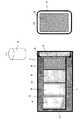
図2(a)及び(b)に示すように、圧力容器3は、本体5と、その本体5を閉じる蓋6とを備えている。なお、図2(a)は圧力容器3の縦断面図、(b)は蓋側から見た側面図である。蓋6にはトレイ7が一体に取り付けられている。トレイ7には所定数、例えば4個のカップ8…8を並べて搭載可能である。図3に示したように、トレイ7にカップ8を載せた状態で蓋6とトレイ7とは本体5に対して一体的に着脱可能である。なお、蓋6とトレイ7は一体成形されてもよいし、分離結合が可能であってもよい。蓋6と本体5との間の密閉性を確保するため、両者の対向部分には適宜パッキン9が設けられる。図2(c)にも示すように、カップ8は上端が開口する円筒形状であり、その内部には所定量ずつ小分けされた固形物10が収容される。なお、蓋6はトレイ7から分離してもよい。本体5に対して蓋6を開閉可能に取り付けてもよい。
【0024】
図1に示すように、本体5はインデックステーブル4の外周に一定のピッチで取り付けられる。従って、圧力容器3はインデックステーブル4の回転に伴って円形の循環経路11に沿って搬送される。循環経路11上には、カップ8の搬入部12と搬出部13とが設定されている。搬入部12には固形物10を収容したカップ8が搬入ライン15を介して順次供給される。搬出部13は、不図示の無菌充填機と搬出ライン16を介して結ばれる。搬出部13は無菌充填機と同一の無菌チャンバー17の内部に設定されている。また、インデックステーブル4の回転方向に関して無菌チャンバー17の手前には外面殺菌チャンバー18が設けられている。インデックステーブル4の一部は、これらのチャンバー17,18内の無菌領域Z1及び外面殺菌領域Z2に入り込んでいる。
【0025】
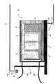
図4は無菌チャンバー17内における圧力容器3及びインデックステーブル4を示している。インデックステーブル4の下面4aの外周にはフランジ4bが全周に亘って設けられている。無菌チャンバー17にはそのフランジ4bが入り込む貯液部17aが設けられており、その貯液部17aの内部には殺菌剤19が蓄えられている。無菌チャンバー17内への取込部分においてインデックステーブル4のフランジ4bは殺菌剤19に浸漬される。
【0026】
また、インデックステーブル4には圧力容器3よりも内周側にオフセットして縦壁20が設けられている。縦壁20もインデックステーブル4の全周に亘って延びている。縦壁20は圧力容器3よりも高く、その上端には貯液部21が全周に亘って設けられている。貯液部21にも殺菌剤19が蓄えられている。無菌チャンバー17にはその貯液部21の殺菌剤19に浸漬されるフランジ17bが設けられている。以上により、インデックステーブル4の上下において無菌チャンバー17内の無菌領域Z1が外部に対してシールされる。なお、殺菌装置1の稼働中、無菌チャンバー17の内部には不図示の無菌エア供給装置から常時無菌エアが供給され、それにより無菌領域Z1は常時陽圧に保たれる。
【0027】
図4から明らかなように、各圧力容器3の本体5には接続手段としてのユーティリティチューブ25,26が取り付けられている。これらのチューブ25,26は縦壁20を貫いてインデックステーブル4の内周側に引き出されている。図1に一部を例示したように、チューブ25,26はインデックステーブル4の回転中心Cの近傍まで延ばされ、そこに設置された不図示のロータリーバルブを介して真空吸引装置27及び蒸気供給装置28とそれぞれ接続される。接続手段は剛性を有する配管によって構成されてもよい。
【0028】
図5は外面殺菌チャンバー18内における圧力容器3及びインデックステーブル4を示している。外面殺菌チャンバー18には、その内部の外面殺菌領域Z2に対して殺菌剤を噴霧するノズル30…30が設けられている。ノズル30は図1に示す殺菌剤供給装置31と接続される。殺菌剤供給装置31は例えば過酸化水素のミスト32をノズル30に供給して各ノズル30から噴霧させる。なお、ここでいうミストとは、過酸化水素水をその沸点以上の高温雰囲気に噴霧(スプレー)して一旦気化させ、気化した過酸化水素成分を凝結させて得られる微細な滴の集合を意味する。このようなミストは、少ない量で十分な殺菌効果が得られ、かつ乾燥も早期に終了するので、本装置1のように連続的な処理を行う途中で殺菌を完了させる手段として好適である。なお、図5に示すように外面殺菌チャンバー18においても、図4の無菌チャンバー17と同様の貯液部18a及びフランジ18bが設けられ、外面殺菌領域Z2が外部からシールされる。さらに、図1に示すように外面殺菌チャンバー18が圧力調整装置33と接続されることにより、装置1の稼働中は外面殺菌領域Z2が僅かに陰圧(外部圧力よりも低い圧力)に維持される。
【0029】
上述したように無菌チャンバー17内の無菌領域Z1及び外面殺菌チャンバー18内の外面殺菌領域Z2が構成されているので、インデックステーブル4は搬出部13において外部と接触せずに回転することができる。
【0030】
次に、殺菌装置1による固形物10の殺菌手順を説明する。殺菌装置1における殺菌処理では、インデックステーブル4が圧力容器3の並ぶピッチを単位として所定のインターバルで間欠的に駆動される。搬入部12では、搬入ライン15から供給される固形物入りのカップ8がトレイ7に載せ換えられる。4つのカップ8がトレイ7に載せられる毎に、搬入部12へ繰り出された空の圧力容器3の本体5にトレイ7及び蓋6が装着されて圧力容器3が密閉される。
【0031】
密閉された圧力容器3が搬出部13へ向かって移動を開始すると、その圧力容器3の空気がチューブ25を介して真空吸引装置27に吸引されて真空脱気が行われる。圧力容器3が所定区間移動する間に真空脱気が完了する。真空脱気が完了した圧力容器3には、蒸気供給装置28からチューブ26を介して蒸気が導入される。これにより圧力容器3の内部が加圧加熱され、蒸気とカップ8内の固形物10とが接触して殺菌が行われる。圧力容器3が所定区間移動する間、蒸気による加圧状態が維持される。その後、真空吸引装置27を利用して、圧力容器3に対する真空脱気が行われる。これにより固形物が冷却される。冷却途中で圧力容器3は外面殺菌領域Z2に移動し、固形物の冷却と並行して圧力容器3の外面が殺菌される。
【0032】
圧力容器3がさらに無菌領域Z1まで移動すると、真空脱気が完了し、搬出部13において蓋6及びトレイ7が本体5から引き出されてカップ8が搬出ライン16に移される。なお、真空脱気の完了後、圧力容器3内に無菌エアを導入して、蓋6の開放前に容器3内の圧力を常圧に戻すようにしてもよい。カップ8の取り出し後、空となった圧力容器3はインデックステーブル4の動作に伴って搬出部13から搬入部12へ返送され、次の殺菌処理に供される。
【0033】
以上の処理が各圧力容器3にて順次繰り返されることにより、搬出部13には殺菌された固形物がほぼ連続して供給される。この結果、効率よく殺菌処理を行える。搬出部13にて一度に大量のカップ8を処理する必要がないので、広大な無菌アキューム領域を設ける必要がなく、搬出部13を無菌チャンバー17内に容易に収容できる。圧力容器3から取り出されたカップ8は逐次無菌充填機側へ送られるので、カップ8内の固形物10が無菌エアに長時間さらされて乾燥が進行するおそれもない。
【0034】
本発明は上述した実施形態に限定されることなく、各種の形態にて実施することができる。例えば搬送機構はカップを円形の搬送経路(循環経路)に沿って循環させる例に限らず、直線状の経路を往復したり、その他、各種の形状の循環経路を移動するものとしてもよい。圧力容器の外面殺菌にはミストに限らず各種の殺菌剤を利用してよい。インデックステーブルに設けられた縦壁を圧力容器よりもオフセットして設ける構成に代え、圧力容器の胴部に縦壁を設けてもよい。無菌チャンバー及び外面殺菌チャンバーにおける上部側の貯液部はチャンバー天井の固定側に設けてもよい。搬入部及び搬出部におけるカップの搬入及び搬出は例えばロボットハンド等によって自動化することができる。保持具はカップ8に限らず、種々の形状としてよい。カップ8は固形物を含んだ製品の容器でもよいし、殺菌処理に専用で使用するものでもよい。なお、圧力容器3には蒸気の凝結等によって発生した液状成分を排出するドレン弁を設けてもよい。
【0035】
図6はさらに他の実施形態を示している。この例では、カップ8を蓋40にて閉じることにより、これらカップ8と蓋40とを圧力容器として機能させるものである。蓋40には接続手段としてのチューブ41を接続し、これを介してカップ8の内部を真空吸引装置27や蒸気供給装置28と接続する。なお、カップ8は図1の例と同様にインデックステーブル4等に載せて搬送することができる。
【0036】
【発明の効果】
以上に説明したように、本発明の殺菌方法及び殺菌装置によれば、圧力容器を搬送しつつ殺菌処理を行うようにしたので、固形物を少量ずつ順次殺菌して連続的な処理を実現することができる。搬出部には、殺菌処理が完了した圧力容器が順に送り込まれるようになり、搬出部にて一度に大量の保持具を処理する必要がなくなる。このため、広大な無菌アキューム領域は不要となる。さらに、一つ一つの圧力容器が小型化されることにより、これらを容易に搬送することができる。しかも、圧力容器内にて保持具を搬送する必要がない。従って、装置が簡素化され、実用化に有利である。
【図面の簡単な説明】
【図1】本発明の殺菌装置の平面図。
【図2】図1の殺菌装置で使用する圧力容器、及びその内部に収容するカップを示す図。
【図3】圧力容器の本体に対して蓋を開閉する途中の状態を示す図。
【図4】無菌チャンバーのシール構造を示す図。
【図5】外面殺菌チャンバーのシール構造を示す図。
【図6】本発明の他の殺菌装置を示す図。
【符号の説明】
1 殺菌装置
2 搬送機構
3 圧力容器
4 インデックステーブル
5 本体
6 蓋
7 トレイ
8 カップ(保持具)
10 固形物
11 循環経路
12 搬入部
13 搬出部
17 無菌チャンバー
18 外面殺菌チャンバー
25,26 ユーティリティチューブ(接続手段)
27 真空吸引装置
28 蒸気供給装置
30 ノズル(殺菌剤供給手段)
31 殺菌剤供給装置(殺菌剤供給手段)
33 圧力調整装置(圧力調整手段)
40 蓋
41 チューブ
Z1 無菌領域
Z2 外面殺菌領域[0001]
BACKGROUND OF THE INVENTION
The present invention relates to a method and an apparatus for sterilizing a solid contained in a cooked food contained in a container by directly contacting the solid with a heat medium such as steam.
[0002]
[Prior art]
As a sterilization method for cooked foods, an indirect heating sterilization method has been used in which the cooked food is packaged and sealed, and then the bag is stored in a retort kettle and heated to a high temperature. It had been. However, in the indirect sterilization method through a bag, both the liquid component and the solid are heated under the same conditions. The heat conduction of the liquid component gradually sterilizes to the center of the solid. And the liquid component are both overheated and the flavor is impaired.
[0003]
Accordingly, various direct heat sterilization methods have been proposed and implemented in which solid materials are directly sterilized by contact with steam. In the sterilization of solids by the direct heat sterilization method, the solids are weighed before sterilization and divided into predetermined amounts, and the divided solids are accommodated in a cup. Each cup is accommodated in the same sterilization pot (corresponding to a pressure vessel). After the sterilization pot is sealed, the inside thereof is vacuumed, and then steam is introduced into the sterilization pot. After heating with steam is continued for a predetermined time, vacuum cooling is performed, and then each cup is removed from the sterilization pot. According to such a direct heat sterilization method, since the solid is in direct contact with the steam, the sterilization conditions suitable for the solid can be set, the heat treatment is completed in a short time, and the flavor of the solid is not impaired. Since it is measured before sterilization and divided into units of packaging units, there is an advantage that it can be easily adapted to individualization as compared with the case where the solid is measured after sterilization and divided.
[0004]
[Problems to be solved by the invention]
However, the direct heat sterilization method so far is a so-called batch process in which a large number of cups are accommodated in the same sterilization pot and processed at a time. Therefore, if it is going to raise processing capacity, it is necessary to enlarge a sterilization pot, and the installation area of an apparatus will increase. After the sterilization treatment, it is necessary to take out a large number of cups at once, and the work must also be performed in a sterile environment. Therefore, it is necessary to secure a large aseptic accumulation area on the outlet side of the sterilization pot, and the equipment is further increased. Scale up. When a large number of sterilized cups are taken out from the sterilization pot to the sterile accumulator area at once, and then the solids are sequentially taken out from each cup and sent to the subsequent process, the solids in each cup are held in the aseptic accumulator area. The time required varies greatly before and after processing. Since sterile air is constantly supplied and maintained at a positive pressure in the sterile accumulator area, the longer the time it is held inside, the more the solids are dried and the quality varies.
[0005]
In order to eliminate these disadvantages, for example, in the sterilization apparatus of Japanese Patent No. 2907663, a plurality of sterilizers are arranged, and a cassette containing a predetermined number of cups is selectively put into each sterilizer, thereby allowing a plurality of sterilizers to be placed. Batch processing is performed in parallel with a sterilizer, and solids are continuously taken out. However, it is necessary to accommodate all the outlet sides of the plurality of sterilizers in the aseptic accumulator area, which also increases the aseptic accumulator area.
[0006]
In Japanese Patent No. 2815089, a sterilization treatment tank partitioned into a plurality of treatment chambers is prepared for each process, and a cup containing solids is sequentially sent to each treatment chamber, thereby continuously in a single treatment tank. An apparatus for sterilization has been proposed. However, it is difficult to hermetically divide the inside of a single processing tank into a plurality of processing chambers in this way, and the inside of the processing tank is exposed to a vacuum or a high temperature environment, so that the cup can be transported in the processing tank. difficult. Therefore, in the apparatus of the publication, the processing tank itself is swung in a seesaw shape to transport the cup, but as a practical problem, it is difficult to put such a mechanism into practical use.
[0007]
The present invention has been made in view of the above circumstances, and an object of the present invention is to provide a sterilization method and a sterilization apparatus that can continuously process a solid by a predetermined amount with a configuration different from the conventional one.
[0008]
[Means for Solving the Problems]
Hereinafter, the sterilization method and sterilization apparatus of the present invention will be described. In order to facilitate understanding of the present invention, reference numerals in the accompanying drawings are appended in parentheses, but the present invention is not limited to the illustrated embodiment.
[0009]
Sterilization method of the present invention,each of the plurality of pressure vessels (3),driving the driving device of the transport mechanism while conveying on the transport mechanism at loading unitwhich is set to a predeterminedcirculation path (12)Thus, each pressure vessel is sequentially movedalong the circulation path to the carry-out section (13) in the aseptic region (Z1), and the carry-in section holds aplurality of holdings in which a predetermined amount of solid matter (10) is accommodated. the pressure vessel was individually sealed ingredients(8) is inserted into each pressure vessel, the interior of the pressure vessel during movementto the unloading unit from the loading unit, executes a process for sterilizing solids In the unloading unit, each pressure vessel is opened to take out the holder and the solid matter from the pressure vessel, and the empty pressure vessel is removed from the unloading unit to the carry-in unitby using the driving device of the transport mechanism. And returningalong the circulation path .
[0010]
According to this sterilization method, since the sterilization is performed while sequentially transporting the pressure vessels, the number of holders accommodated in the pressure vessels is limited to, for example, several, and the number of pressure vessels is increased in exchange for the limitation. Thus, even if the sterilization process itself in each pressure vessel is a batch type, as a whole, it is possible to realize a continuous process by sequentially sterilizing the solid matter little by little. Pressure containers that have been sterilized are sequentially fed into the carry-out unit, and there is no need to process a large number of holders at once in the carry-out unit. For this reason, a vast aseptic accumulator area becomes unnecessary. Furthermore, since each pressure vessel is reduced in size, these can be easily conveyed. In addition, there is no need to transport the holder in the pressure vessel. Therefore, the apparatus is simplified.
[0011]
In the sterilization method of the present invention, it is desirable to divide the outer surface sterilization region (Z2) before the sterilization region and to perform the outer surface sterilization treatment on the pressure vessel introduced into the outer surface sterilization region. According to this, the outer surface of the pressure vessel is sterilized before being taken into the aseptic area. Therefore, it is not necessary to install the part from the carrying-in part to the outer surface sterilization area in an aseptically treated environment. Furthermore, when the inside of the outer surface sterilization area is maintained at a negative pressure, the sterilization area is maintained at a positive pressure, so the atmosphere of the outer surface sterilization area does not affect the sterilization area, and the outer surface sterilization area The sterility of the aseptic area is more reliably ensured.
[0012]
In the sterilization method of the present invention, the solid is typically mixed with a liquid component to constitute a cooked food, but various other solids may be sterilized according to the present invention. The holder for storing the solid material may be formed in various shapes such as a cup shape and a tray shape. The product container itself may be used as a holder, or a dedicated holder may be used for sterilization.
[0013]
In the sterilization method of the present invention, the treatment for sterilizing the solid is performed by vacuum degassing the inside of the pressure vessel, by introducing steam into the pressure vessel and pressurizing and heating the inside of the pressure vessel, And a process of cooling the solid matter by vacuum degassing the inside of the pressure vessel into which the steam is introduced. However, an appropriate process may be added, changed, or deleted depending on the solid matter.
[0014]
The sterilization apparatus of the present invention has a plurality of pressure vessels (3)that contain aplurality of holders (8) containing a predetermined amount of solid matter (10) and can be individually sealed, and adrive device.Each of the plurality of pressure vesselsiscirculatedusing the drive of the drive device betweena carry-in part (12)set in a predeterminedcirculation path and a carry-out part (13) in the aseptic region (Z1). A transport mechanism (2)that circulatesalong the path; and connection means (25, 26) for connecting each of the plurality of pressure vessels to ancillary equipment (27, 28) for sterilization treatment. It is characterized by that.
[0015]
According to the present invention, the pressure vessel is circulated by the transport mechanism, and in the carry-in portion, the pressure vessel is sealed by attaching a predetermined number of holders to each pressure vessel, and the pressure vessel heading from the carry-in portion toward the carry-out portion. On the other hand, it is possible to carry out the sterilization method of the present invention by performing sterilization treatment through the connecting means to sterilize the solid matter, and opening each pressure vessel in the carry-out part to take out the holder and the solid matter. it can.
[0016]
In the sterilization apparatus of the present invention, an outer surface sterilization region (Z2) is defined in front of the sterilization region, and the sterilization agent supplies the sterilant to the outer surface sterilization region so as to be in contact with the outer surface of the pressure vessel. Supply means (30, 31) may be further provided. In this case, since the outer surface of the pressure vessel is sterilized before being taken into the sterilized area, it is not necessary to install the part from the carry-in part to the outer sterilized area in an aseptic process, and the apparatus can be installed and handled. It becomes easy. When the pressure adjusting means (33) for maintaining the inside of the outer surface sterilization region at a negative pressure is provided, the outer surface sterilization region functions as a buffer region interposed between the sterilization region and the external environment. Is guaranteed more reliably.
[0017]
In the sterilizing apparatus of the present invention, each pressure vessel includes a main body (5) for housing the holder and a lid (6) for closing the main body, and the tray supports the holder. (7) may be provided integrally. In this case, the holding of the holder and the sealing of the pressure vessel are completed simply by placing a predetermined number of holders on the tray and inserting them into the main body. When taking out the holder, it is only necessary to remove the lid from the main body and pull out the tray as it is. Therefore, carrying-in and carrying-out work can be performed skillfully. Note that the term “integral” as used herein means that the lid and the tray can be integrally attached to and detached from the main body, and the lid and the tray are separately manufactured in addition to the case where the lid and the tray are integrally formed. Structures that are combined afterward are also included in the integrated concept.
[0018]
In the sterilization apparatus of the present invention, the circulation path of each pressure vessel may be circular. In this case, each pressure vessel moves while maintaining a constant distance with respect to the center (C) of the circulation path. Therefore, when connecting incidental equipment and each pressure vessel by connection means, such as piping and a flexible tube, piping and a tube can be drawn comparatively easily by passing through the central part of a circulation path.
[0019]
The sterilization apparatus of the present invention can further include a vacuum suction device (27) and a steam supply device (28) as the incidental equipment. In this case, the solid matter can be sterilized by the direct heat sterilization method by performing vacuum degassing, pressure heating with steam, cooling with vacuum degassing, or the like on the pressure vessel being conveyed. However, the incidental facilities are not limited to these, and other devices may be added and replaced with other devices.
[0022]
DETAILED DESCRIPTION OF THE INVENTION
FIG. 1 shows a plan view of a sterilizer according to an embodiment of the present invention. The
[0023]
As shown in FIGS. 2A and 2B, the
[0024]
As shown in FIG. 1, the main body 5 is attached to the outer periphery of the index table 4 at a constant pitch. Therefore, the
[0025]
FIG. 4 shows the
[0026]
The index table 4 is provided with a
[0027]
As apparent from FIG. 4,
[0028]
FIG. 5 shows the
[0029]
As described above, since the sterilization area Z1 in the
[0030]
Next, the procedure for sterilizing the
[0031]
When the sealed
[0032]
When the
[0033]
By sequentially repeating the above processing in each
[0034]
The present invention is not limited to the embodiments described above, and can be implemented in various forms. For example, the transport mechanism is not limited to the example in which the cup is circulated along the circular transport path (circulation path), and may reciprocate along a linear path or move in various other circulation paths. For sterilization of the outer surface of the pressure vessel, not only mist but also various sterilizing agents may be used. Instead of the configuration in which the vertical wall provided in the index table is offset from the pressure vessel, the vertical wall may be provided in the body portion of the pressure vessel. The upper side liquid storage part in the aseptic chamber and the outer surface sterilization chamber may be provided on the fixed side of the chamber ceiling. The loading and unloading of the cup in the loading section and the unloading section can be automated using, for example, a robot hand. The holder is not limited to the
[0035]
FIG. 6 shows still another embodiment. In this example, the
[0036]
【The invention's effect】
As described above, according to the sterilization method and sterilization apparatus of the present invention, since the sterilization process is performed while the pressure vessel is being conveyed, the solid material is sequentially sterilized little by little to realize a continuous process. be able to. Pressure containers that have been sterilized are sequentially fed into the carry-out unit, and there is no need to process a large number of holders at once in the carry-out unit. For this reason, a vast aseptic accumulator area becomes unnecessary. Furthermore, since each pressure vessel is reduced in size, these can be easily conveyed. In addition, there is no need to transport the holder in the pressure vessel. Therefore, the apparatus is simplified, which is advantageous for practical use.
[Brief description of the drawings]
FIG. 1 is a plan view of a sterilizer according to the present invention.
FIG. 2 is a view showing a pressure vessel used in the sterilizer of FIG. 1 and a cup accommodated therein.
FIG. 3 is a view showing a state in the middle of opening and closing the lid with respect to the main body of the pressure vessel.
FIG. 4 is a view showing a seal structure of a sterile chamber.
FIG. 5 is a view showing a seal structure of an outer surface sterilization chamber.
FIG. 6 is a view showing another sterilization apparatus of the present invention.
[Explanation of symbols]
DESCRIPTION OF
DESCRIPTION OF
27
31 Disinfectant supply device (disinfectant supply means)
33 Pressure adjusting device (pressure adjusting means)
40
Claims (10)
Translated fromJapanese前記搬入部では、所定量の固形物が収容された複数の保持具を各圧力容器に挿入して該圧力容器を個別に密閉し、
前記搬入部から前記搬出部へと移動中の各圧力容器の内部では、固形物を殺菌するための処理を実行し、
前記搬出部では各圧力容器を開放して保持具及び固形物を圧力容器から取り出し、
前記搬送機構の前記駆動装置の駆動を利用して、空の圧力容器を前記搬出部から前記搬入部へと前記循環経路に沿って返送する、ことを特徴とする固形物の殺菌方法。Each pressure vessel is sterilized along the circulation path by driving the driving device of the transport mechanism while transporting each of the plurality of pressure containers onto the transport mechanism at the carry-in portion set to a predetermined circulation path. Move sequentially to the unloading section in the area,
In the carry-in portion, a plurality of holders containing a predetermined amount of solid matter are inserted into each pressure vessel to individually seal the pressure vessel,
Inside each pressure vessel moving from the carry-in part to the carry-out part, a process for sterilizing solids is performed,
In the unloading part, each pressure vessel is opened to remove the holder and the solid matter from the pressure vessel,
A solid matter sterilization method, wherein an empty pressure vessel is returned from the carry-out unit to the carry-in unit along the circulation path by using driving of the driving device of the transport mechanism.
駆動装置を有し、前記複数の圧力容器のそれぞれを、所定の循環経路に設定された搬入部と無菌領域内の搬出部との間で前記駆動装置の駆動を利用して前記循環経路に沿って循環させる搬送機構と、
前記複数の圧力容器のそれぞれを、殺菌処理用の付帯設備と接続するための接続手段と、
を具備することを特徴とする固形物の殺菌装置。A plurality of pressure vessels that contain a plurality of holders containing a predetermined amount of solid matter and can be individually sealed; and
A drive device, and each of the plurality of pressure vessels is moved along the circulation path by utilizing the drive of the drive device between a carry-in portion set in a predetermined circulation route and a carry-out portion in the sterile region. A transport mechanism that circulates
Connection means for connecting each of the plurality of pressure vessels to ancillary equipment for sterilization,
A solid matter sterilization apparatus comprising:
Priority Applications (2)
| Application Number | Priority Date | Filing Date | Title |
|---|---|---|---|
| JP2002046872AJP4031260B2 (en) | 2002-02-22 | 2002-02-22 | Solid matter sterilization method and sterilizer |
| CNB03106180XACN1313035C (en) | 2002-02-22 | 2003-02-20 | Solid sterilizing method and sterilizer thereof |
Applications Claiming Priority (1)
| Application Number | Priority Date | Filing Date | Title |
|---|---|---|---|
| JP2002046872AJP4031260B2 (en) | 2002-02-22 | 2002-02-22 | Solid matter sterilization method and sterilizer |
Related Child Applications (1)
| Application Number | Title | Priority Date | Filing Date |
|---|---|---|---|
| JP2007244979ADivisionJP2007330272A (en) | 2007-09-21 | 2007-09-21 | Solid matter sterilization method |
Publications (2)
| Publication Number | Publication Date |
|---|---|
| JP2003245060A JP2003245060A (en) | 2003-09-02 |
| JP4031260B2true JP4031260B2 (en) | 2008-01-09 |
Family
ID=27800007
Family Applications (1)
| Application Number | Title | Priority Date | Filing Date |
|---|---|---|---|
| JP2002046872AExpired - Fee RelatedJP4031260B2 (en) | 2002-02-22 | 2002-02-22 | Solid matter sterilization method and sterilizer |
Country Status (2)
| Country | Link |
|---|---|
| JP (1) | JP4031260B2 (en) |
| CN (1) | CN1313035C (en) |
Cited By (2)
| Publication number | Priority date | Publication date | Assignee | Title |
|---|---|---|---|---|
| US8205766B2 (en) | 2009-05-20 | 2012-06-26 | The Bergquist Company | Method for packaging thermal interface materials |
| US8430264B2 (en) | 2009-05-20 | 2013-04-30 | The Bergquist Company | Method for packaging thermal interface materials |
Families Citing this family (5)
| Publication number | Priority date | Publication date | Assignee | Title |
|---|---|---|---|---|
| JP2005096817A (en)* | 2003-09-25 | 2005-04-14 | Asahi Breweries Ltd | Processing equipment |
| CN102633106A (en)* | 2012-04-24 | 2012-08-15 | 无锡凯夫制药有限公司 | Medicine-bottle transporting device for sterile room |
| CN109275835A (en)* | 2017-07-21 | 2019-01-29 | 广州卓诚食品科技有限公司 | Aseptic canning process and aseptic canning system |
| CN111470279B (en)* | 2020-04-16 | 2021-08-31 | 上海先惠自动化技术股份有限公司 | Conveying line for sterile in-and-out of sterile room |
| CN111789989A (en)* | 2020-08-11 | 2020-10-20 | 山东新华医疗器械股份有限公司 | Continuous sterilization system |
Family Cites Families (3)
| Publication number | Priority date | Publication date | Assignee | Title |
|---|---|---|---|---|
| JPH0647230B2 (en)* | 1987-07-29 | 1994-06-22 | 株式会社日立製作所 | Disk processing method and apparatus |
| EP0780056A1 (en)* | 1995-12-22 | 1997-06-25 | Societe Des Produits Nestle S.A. | Apparatus and method for treating a fluid product |
| ES2304803T3 (en)* | 1999-04-29 | 2008-10-16 | Sidel S.P.A. | CONTINUOUS METHOD AND APPLIANCE FOR THE STERILIZATION OF BOTTLED BEVERAGES. |
- 2002
- 2002-02-22JPJP2002046872Apatent/JP4031260B2/ennot_activeExpired - Fee Related
- 2003
- 2003-02-20CNCNB03106180XApatent/CN1313035C/ennot_activeExpired - Fee Related
Cited By (2)
| Publication number | Priority date | Publication date | Assignee | Title |
|---|---|---|---|---|
| US8205766B2 (en) | 2009-05-20 | 2012-06-26 | The Bergquist Company | Method for packaging thermal interface materials |
| US8430264B2 (en) | 2009-05-20 | 2013-04-30 | The Bergquist Company | Method for packaging thermal interface materials |
Also Published As
| Publication number | Publication date |
|---|---|
| JP2003245060A (en) | 2003-09-02 |
| CN1439315A (en) | 2003-09-03 |
| CN1313035C (en) | 2007-05-02 |
Similar Documents
| Publication | Publication Date | Title |
|---|---|---|
| US3035886A (en) | Method of sterilizing | |
| FI94331B (en) | Method and apparatus for sterilizing a container provided with a filling opening | |
| JP4031260B2 (en) | Solid matter sterilization method and sterilizer | |
| KR101653173B1 (en) | Hydrogen peroxide supply device | |
| JPS63138931A (en) | Method of sterilizing cylindrical vessel | |
| JP2002321715A (en) | Aseptic filling method and system | |
| JPS58500661A (en) | Aseptic filling equipment and method for flexible containers | |
| JP2020172297A (en) | Aseptic filling machine and aseptic filling method | |
| JP3528971B2 (en) | Aseptic filling device | |
| JPH0958635A (en) | Aseptic filling and packaging apparatus and sterilization method of aseptic filling and packaging apparatus | |
| JP2007330272A (en) | Solid matter sterilization method | |
| JPH0733123A (en) | External sterilizer | |
| JP3195278B2 (en) | Sterilization method for manufacturing equipment for food in containers | |
| US8967431B2 (en) | Storage container for the provision of media for disinfecting, sterilizing and/or maintaining medical, especially dental, instruments | |
| JPS60123328A (en) | Vessel sterilizer in packer | |
| JPH0958632A (en) | Packaging material sterilizer | |
| JPH0958631A (en) | Method and apparatus for sterilizing packaging material | |
| JPH05330524A (en) | Cooling method and cooling device for container transport plate | |
| JP4467159B2 (en) | Aseptic filling system | |
| CN214285161U (en) | Disinfection is workstation for supply center | |
| JP3096057B2 (en) | Sterilization method in chamber of aseptic filling device and aseptic filling device | |
| JP4601773B2 (en) | Sterilization method, sterilization system and aseptic filling system for pouch with spout | |
| JPH10157713A (en) | Container sterilization method and container sterilization apparatus using hydrogen peroxide and microwave | |
| JPH08173509A (en) | Method and device for sterilizing container using electron beam irradiation device | |
| JPH04239435A (en) | Sterilization of germfree filling container |
Legal Events
| Date | Code | Title | Description |
|---|---|---|---|
| A621 | Written request for application examination | Free format text:JAPANESE INTERMEDIATE CODE: A621 Effective date:20050218 | |
| A977 | Report on retrieval | Free format text:JAPANESE INTERMEDIATE CODE: A971007 Effective date:20060227 | |
| A131 | Notification of reasons for refusal | Free format text:JAPANESE INTERMEDIATE CODE: A131 Effective date:20070424 | |
| A521 | Written amendment | Free format text:JAPANESE INTERMEDIATE CODE: A523 Effective date:20070625 | |
| A131 | Notification of reasons for refusal | Free format text:JAPANESE INTERMEDIATE CODE: A131 Effective date:20070724 | |
| A521 | Written amendment | Free format text:JAPANESE INTERMEDIATE CODE: A523 Effective date:20070921 | |
| TRDD | Decision of grant or rejection written | ||
| A01 | Written decision to grant a patent or to grant a registration (utility model) | Free format text:JAPANESE INTERMEDIATE CODE: A01 Effective date:20071016 | |
| A61 | First payment of annual fees (during grant procedure) | Free format text:JAPANESE INTERMEDIATE CODE: A61 Effective date:20071018 | |
| R150 | Certificate of patent or registration of utility model | Free format text:JAPANESE INTERMEDIATE CODE: R150 | |
| FPAY | Renewal fee payment (event date is renewal date of database) | Free format text:PAYMENT UNTIL: 20101026 Year of fee payment:3 | |
| FPAY | Renewal fee payment (event date is renewal date of database) | Free format text:PAYMENT UNTIL: 20111026 Year of fee payment:4 | |
| FPAY | Renewal fee payment (event date is renewal date of database) | Free format text:PAYMENT UNTIL: 20121026 Year of fee payment:5 | |
| FPAY | Renewal fee payment (event date is renewal date of database) | Free format text:PAYMENT UNTIL: 20121026 Year of fee payment:5 | |
| RD04 | Notification of resignation of power of attorney | Free format text:JAPANESE INTERMEDIATE CODE: R3D04 | |
| FPAY | Renewal fee payment (event date is renewal date of database) | Free format text:PAYMENT UNTIL: 20131026 Year of fee payment:6 | |
| LAPS | Cancellation because of no payment of annual fees |